


WLAN Access Point
User Manual
Sep.27.02

Instruction Manual
Federal Communication Commission Interference Statement
This equipment has been tested and found to comply with the limits for a Class B digital device, pursuant to
Part 15 of the FCC Rules. These limits are designed to provide reasonable protection against harmful
interference in a residential installation. This equipment generates, uses and can radiated radio frequency
energy and, if not installed and used in accordance with the instruc tions, may cause harmful interference to
radio communications. However, there is no guarantee that interference will not occur in a particular
installation. If this equipment does cause harmful interference to radio or television reception, which can be
determined by turning the equipment off and on, the user is encouraged to try to correct the interference by
one of the following measures:
- Reorient or relocate the receiving antenna.
- Increase the separation between the equipment and receiver.
- Connect the equipment into an outlet on a circuit different from that to which the receiver is connected.
- Consult the dealer or an experienced radio/TV technician for help.
-
FCC Caution: To assure continued compliance, (example – use only shielded interface cables when
connecting to computer or peripheral devices). Any changes or modifications not expressly approved by the
party responsible for compliance could void the user’s authority to operate this equipment.
FCC Radiation Exposure Statement
This equipment complies with FCC radiation exposure limits set forth for an uncontrolled environment. This
equipment should be installed and operated with minimum distance 20 cm between the radiator & your body.
This device complies with Part 15 of the FCC Rules. Operation is subject to the following two conditions: (1)
This device may not cause harmful interference, and (2) this device must accept any interference received,
including interference that may cause undesired operation.

Table of Contents
Chapter 1 Introduction 1
1.1 Package Contents 1
1.2 Features 1
1.3 System Requirement 1
1.4 Hardware Description 2
Chapter 2 Connecting the WLAN Access Point to Your Network 2
Chapter 3 Configuring the Wireless Point 3
Chapter 4 Installing the USB Drivers for the WLAN Access Point 4
4.1 Installing the Driver software for Windows 98 4
Chapter 5 WLAN Access Point Utility 5
5.1 Install Access Point Utility 5
5.2 Configuring the W LAN Access Point with USB Port / AP Utility 8
5.3 Configuring the W LAN Access Point with Ethernet Port
/ SNMP Utility 12
Chapter 6 WLAN Access Point Firmware Upgrade with Ethernet
Port / TFTP Client Utility 21
Chapter 7 Application and Note 22
Chapter 8 Q & A 29

1. Introduction
Based on IEEE 802.11b, WLAN Access Points provide a cost effective way for mobile users to connect to
their corporate Ethernet-based LANs. With the slick Windows based user interface designs, corporate IT
specialists can easily deploy and manage WLAN Access Points in their environments. In addition to corporate
uses, WLAN Access Points are for applications in public areas such as airports, hotels, fast-food restaurants,
etc. People with mobile computers can use services offered by WLAN Access Point within these areas to
connect to the Internet with virtually no effort. Please read this manual to get familiar with the WLAN Access Point.
This manual contains detailed instructions in operation of this product. Please keep this manual for future reference.
1.1 Package Contents
The WLAN Access Point includes the following items:
a. WLAN Access Point
b. The CD including:
1. WLAN Access Point Utility & Driver software
2. User’s Manual (this document)
c. USB Cable
1.2 Features
l Plug and Play installation
l Roaming function provides full mobility
l Control via USB port
l Data packets bridging between an IEEE 802.11b wireless network and an Ethernet network
l Windows-based user interfaces for configuration, and monitoring
l Wireless data encryption with 64 and 128 bits encryption for security
l Dual antennas with diversity function
l Supports RTS threshold control for better throughput
l Auto fallback data rate under noisy environment
l Supports SNMP utility management
1.3 System Requirement
l Computer with USB support or Ethernet connection
l Windows 98, Windows ME, Windows 2000, Windows XP.
1

1.4 Hardware Description
l This section mainly describes the hardware of WLAN Access Point.
The physical dimensions of the WLAN Access Pont is: 145mm(W) X 85mm(D) x 26mm(H)
Power Indicator
WLAN/LAN
Indicators
The front panel consists of LED Indicators.
l Reset Button
The reset button is located at the rear side of WLAN Access Point, when pressing one second
on this reset button, you can reset the WLAN Access Point, this action takes place after a user makes
configuration changes in order to initiate the changes. And when keeping pressing six seconds on this
reset button, you can restore the factory default values of the WLAN Access Point.
Chapter 2 Connecting the WLAN Access Point to Your Network
1. Locate an optimum location for the WLAN Access Point. The best place for your WLAN Access Point is
usually at the center of your wireless network, with line of sight to all of your mobile stations.
2. Fix the direction of the antenna. Try to place it in a position, which can best cover your wireless network.
Normally, the higher you place the antenna, the better the performance will be. The antenna’s position
enhances the receiving sensitivity.
3. Connect an RJ -45 connector to the WLAN Access Point. Then, connect the other end of the Ethernet
cable to a switch or hub. The WLAN Access Point will then be connected to your 10/100 Network.
4. Connect USB cable to the WLAN Access Point. Then, connect the other end of USB cable to your
computer.
5. Connect the AC Power Adapter to the WLAN Access Point’s Power Socket. Only use the power adapter
supplied with the WLAN Access Point. Use of a different adapter may result in product damage.
6. The Hardware Installation is complete.
2

Chapter 3 Configuring the WLAN Access Point
The WLAN Access Point can be configured one of two ways, through the AP Utility or the SNMP Manager.
AP Utility
The AP Utility can be used when configuring the WLAN Access Point through a USB connection and is
compatible with Windows 98, Windows ME, Windows 2000, Windows XP.
SNMP Manager
The WLAN Access Point SNMP Manager can be used when configuring the WLAN Access Point through an
Ethernet connection and is Windows 98, Windows ME, Windows 2000, Windows XP.
DEFAULT SETTINGS:
IP Address: 192.168. 168.10
SubNet Mask: 255.255.255.0
ESSID: AP
3
Chapter 4 Installing the USB Drivers for the WLAN Access Point
4.1 Installing the Driver Software
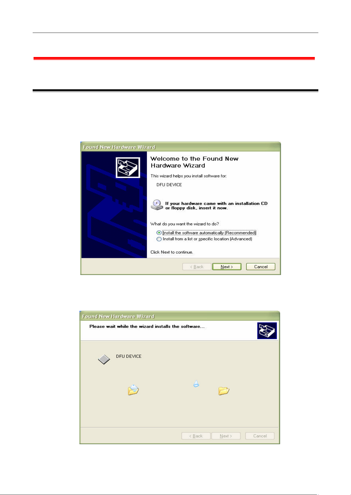
1. Windows OS will automatically identify the WLAN Access Point, once USB Cable is connected to the PC,
and prompt you to install the necessary driver.
Make sure that the Setup CD is inserted into your CD-ROM drive and click the
Next button on the Add New Hardware Wizard screen to proceed.
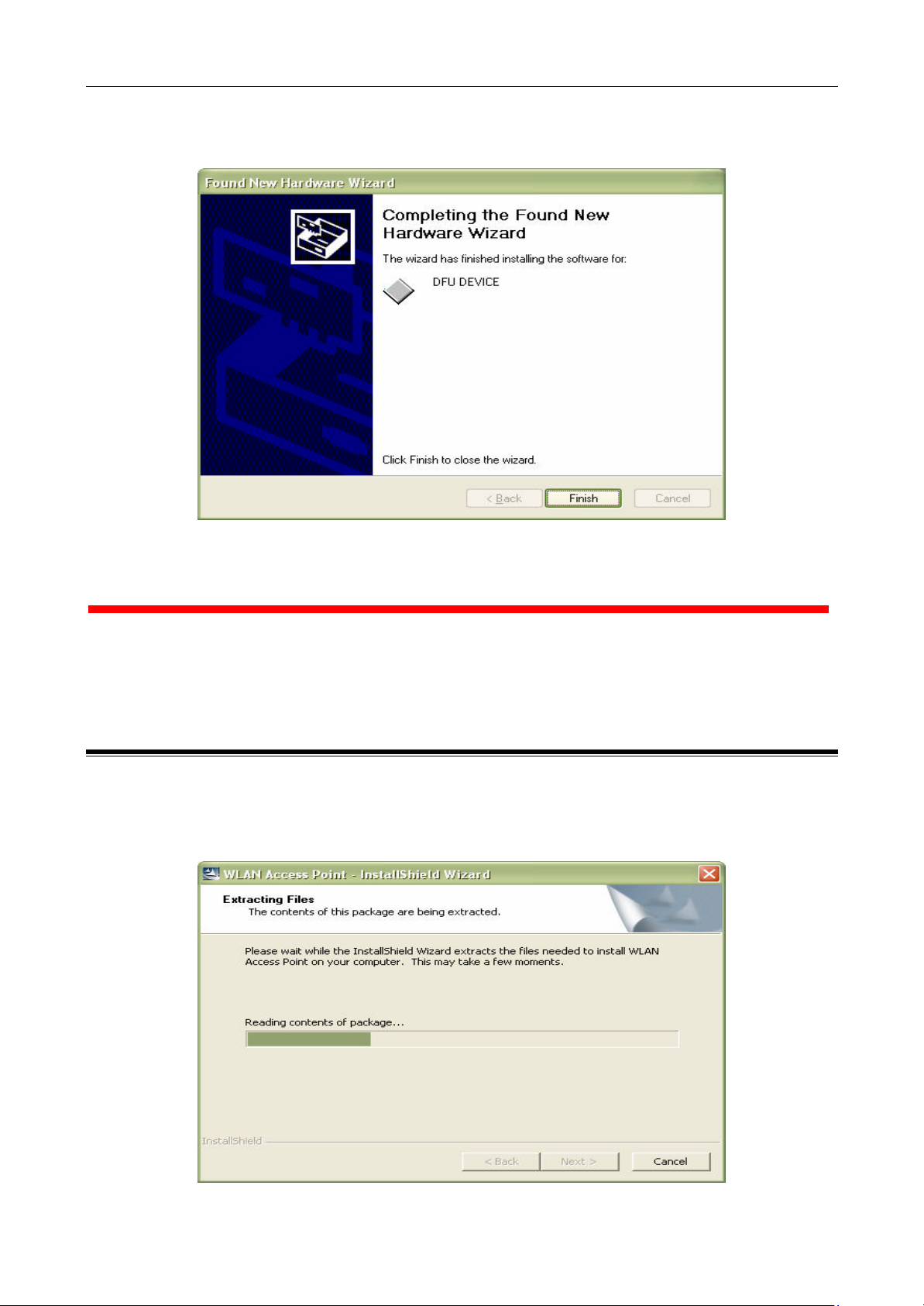
2. Windows will now search for the driver. After Windows has acknowledged finding the driver, click the
Next button.
4
3. Windows will now install the driver files. Click the Finish button when completed.
Chapter 5 WLAN Access Point Utility
The WLAN Access Point Utility is provided to allow you furt her customization of the WLAN Access Point through
USB port or Ethernet port.
5.1 Install WLAN Access Point Utility
1. To install the WLAN Access Point Utility, first put the Setup CD into your CD-ROM drive.
2. Select Run from the Start menu. Type “E:\WLAN Access Point\Utility\Setup.exe” in the Open
box (where is your CD-ROM drive) and click OK.
5
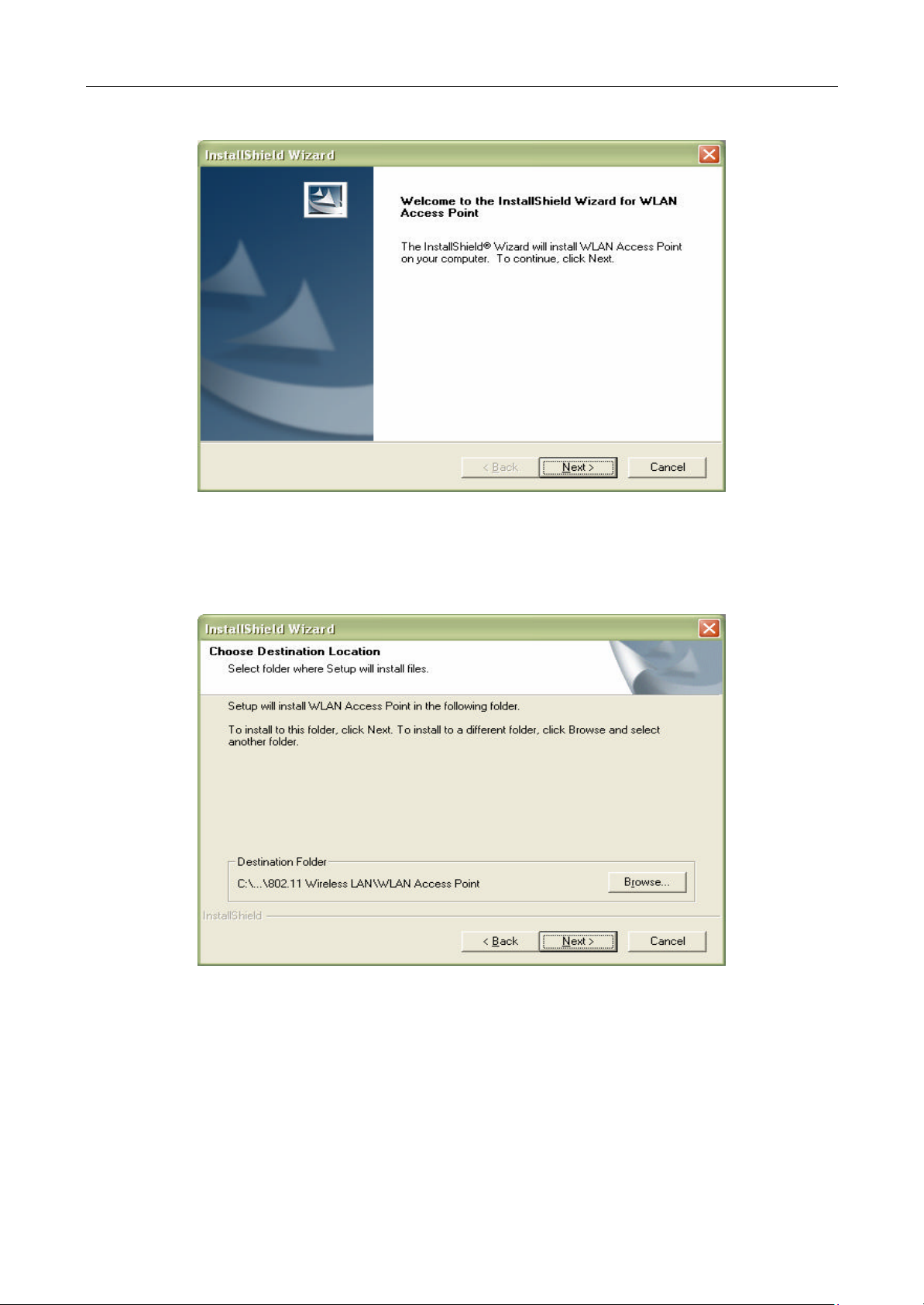
3. This will bring up the Welcome screen. After reading this screen, click the Next button to continue.
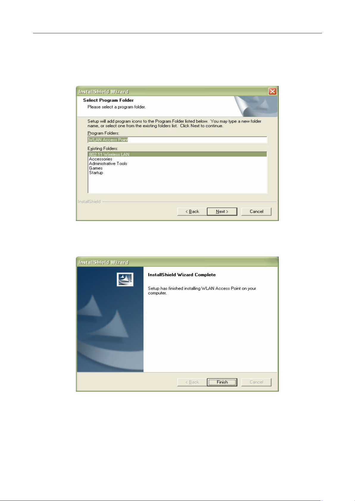
4. The Destination screen will show you the default destination chosen by the utility. If you should want to
install this in another location, click the Browse button and select an alternate destination. When you are
ready to continue, click the Next button
6
5. The next screen will show the Program Folder that the utility will use. If you want to put the utility in
another Program Folder, click an Existing Folder or, if you don’t want to run this out of a Program Folder,
delete the Program Folder name. Then, click the Next button to continue.
6. The Utility has now been installed. Then complete installation.
7

5.2 Configuring the WLAN Access Point with USB Port / AP Utility
AP Utility location:
The AP Utility consist of:
1. Code Download (Firmware upgrade):
2. Utilities (Configuring WLAN Access Point):
8

Code Download (Firmware upgrade):
The WLAN Access Point firmware upgrade can be done through the USB port with AP Utility.
1. Click “ …” button and a dialog box appeared. Select the firmware file as AP Utility, which you want to
upgrade your WLAN Access Point. Then click “Open” button
2. Click “Download” button to process firmware upgrade
3. The AP Utility process firmware upgrade now. Please wait for a moment.
4. Firmware upgrade completed.
Caution: Do not unplug the power adapter of AP, during the firmware upgrade.
Utilities (Configuring Wireless AP):
A. Under the window that appears, there are two options:
The “Get” button in order to view the current parameters of the Wireless AP
The “Set” button to download any changes to the Wireless AP.
B. Configuration Settings: Click “Configuration” bottom, then the “Identifier” and “Value” column
display Wireless AP’s status. From this screen, you can view the status information and modify
the Wireless AP state.
9

• MAC Address. The MAC Address of the WLAN Access Point . Unique 48-bit, hard-coded
Media Access Control address known as the station identifier.
• Regulation Domain. Different Country and region
• Eth_IP_Address. The IP Address of the WLAN Access Point. Network assigned Internet Protocol
address of the WLAN Access Point .
• Eth_SubMask. The Ethernet Station and the WLAN Access Point must be on the same subnet.
The IP address for the WLAN Access Point must correspond to the Subnet Mask.
Subnet Mask consists of four sets of three digits that divide a network into subnetworks.
• Wirel_ESSID. The ESSID (up to 32 printable ASCII characters) of the unit is a string used to
identify a WLAN. The ID prevents the unintentional merging of two co-located WLANs.
• AutoRateFallBack. Select Enable or Disable. When this is enabled the transmission rate is
defined by the past transmission status.
• Wirel_Channel. Select the channel to be used. The channels differ from country to country.
• Wireless Fragmentation Threshold: The size at which packets will be fragmented.
Choose a setting within a range of 256 to 2346bytes.This is the option for the Fragmentation
Threshold activation.
• Wireless RTS Threshold: Minimum packet size to require an RTS (Request To Send).
For packets smaller than this threshold, an RTS is not sent and the packet is transmitted
directly to the WLAN. This is the option for the RTS Threshold activation.
• WEP type: The Wired Equivalent Privacy Algorithm (64 or 128 bits).
• WEP key: The WEP key if the WEP option is enabled in order to activate WEP encryption for
transmissions between the stations and the WLAN Access Point.
10

• WEP Keys #1 - #4: Follow the steps below to set your WEP:
(1) Select the Encryption type: 64bit or 128bit from WEP type.
(2) Type WEP Key: If you select 64bit, you must type 10 values in the following range (0~F) from Key1 to
Key 4 space. Besides, if you select 128 bit, you must type 26 values (0~F) in each WEP Key from Key 1
to Key 4. Please note that all the WEP Keys (key1~key4) have to be filled.
(3) Select WEP Key: Select one of WEP Key from Key1 to Key4 for using.
• Preamble: Select Short or Long Preamble Type. Preamble is the first subfield of PPDU,
which is the appropriate frame format for transmission to PHY (Physical layer).
There are two options, Short Preamble and Long Preamble.
• Authentication Type: Select Open System or Shared Key Authentication Type.
a. Open System: With this setting any station in the WLAN can associate with a WLAN Access Point
and receive and transmit data (n ull authentication).
b. Shared Key: With this setting only stations using a shared key encryption identified by the
WLAN Access Point is allowed to associate with it.
c. Both: With this setting stations communicate with or without data encryption.
• Access Point Name: Type the Wireless AP’s name.
• Operational Rate Set: By default the unit adaptively selects the highest possible rate for transmission.
In case of obstacles or interference, the system will step down. Select the basic rates to be used
among the following options: 1 - 2 (Mbps), 1 - 2 - 5.5 – 11 (Mbps). Select the Operational Rate set
among the following options, “5.5Mb , 11Mb” (1 – 2 - 5.5 - 11 Mbps) or “1Mb , 2Mb” (1 - 2 Mbps).
• Beacon Period: Set the Beacon Period parameter, which specifies the duration between beacon packets
(milliseconds). The range for the beacon period is between the range 20 -1000 with a typical value of 100.
• DTIM: Set the DTIM period. Determines at which interval the AP will send its broadcast traffic.
Default value is 2 beacons.
• Antenna: Set the Antenna among the following options Left, Right or Diversity, to determine which
antennas are used for reception. (Antenna figure shown as in below)
• Operational Mode: Set one of the following operational modes for the WLAN Access Point .
• Access Point
• Wireless Repeater
For more information on each mode of operation see “Chapter 7 Application and Note”.
• User Community: Indicates the user’s password. The default password is “public”
• User Access: Indicates the user’s access for READ only right.
• Administrator Community: Indicates the administrator’s password. The default password
is “public”.
• Administrator Access: Indicates the Administrator’s access for READ/WRITE rights.
• Dhcp Client: Enable/Disable automatic IP Address assignment by the DHCP server Primary Port:
Determines the WLAN Access Point’s IP Address.
• Primary Port: The interface, which determines the DHCP server (Ethernet Port/Wireless Port).
• Preferred BSSID: Remote MAC Address for connection, in Wireless Repeater operational mode.
11

• SSID Broadcasting: Enable or disable SSID broadcasting.
NOTE:
Right side antenna
Left side antenna
5.3 Configuring the Wireless AP with Ethernet Port / SNMP Utility
SNMP Utility location:
Start SNMP Manager function:
1. Connect an Ethernet station and the WLAN Access Point on the same subnet.
Also the IP address for WLAN Access Point must correspond to the Subnet mask.
NOTE: When connecting to AP, you need to make sure if the station IP address and the Subnet mask
are configured properly.
2. Execute SNMP manager application, under “ File ” menu:
12

• Connect to Access Point: Directly connect with the Wireless AP by first typing its
IP Address in the panel which appears and then at the Community field, type the appropriate
password (default password: public)
Press “OK” button for connection
Note: In Authority mode, if selecting User mode, every menu in this SNMP Manager can be read only.
On the Administrator mode, user can read or configure those menus anytime.
• Find Access Point: This submenu allows you to find and connect with a WLAN Access Point
without the necessity of knowing its IP Address. Choose this submenu in order to find the
WLAN Access Point available for connection.
Select one of the available AP and press “Connect”. Then “Connect to Access Point” dialog appears.
Type the appropriate password (default password: public) in the Community field
13

Press “OK” button for connection
3. Now, if “Get Configuration done” appears below then you can use SNMP manager to configure the
Wireless AP.
File Menu:
• Close Connection AP
Terminates the connection with the WLAN Access Point.
• Download Changes
When all the desired values of the parameters have been set you are able to download the
changes (save the changes) to the WLAN Access Point by selecting this submenu.
• Options
Defines the polling interval according to which the WLAN Access Point Configuration polls the WLAN
Access Point in order to update the statistics and the Associated Stations List.
Setup Menu:
• Bridge: Under the “Bridge” submenu, there are two options:
a) IP Configuration
14

• MAC Address. The MAC Address of the WLAN Access Point. Unique 48-bit, hardcoded
Media Access Control address known as the station identifier.
• IP Address. The IP Address of the WLAN Access Point . Network-assigned Internet Protocol address
of the WLAN Access Point .
• IP Mask. The Ethernet Station and the WLAN Access Point must be on the same subnet.
The IP address for the WLAN Access Point must correspond to the Subnet Mask.
Subnet Mask consists of four sets of three digits that divide a network into subnetworks
• DHCP Client Enable : DHCP client is enabled the IP Address field displays the IP Address that was
dynamically assigned to the WLAN Access Point by the network DHCP server and the IP Mask field
displays the IP Mask utilized by the network DHCP server. Additionally you have to select the Primary
Port which is the interface that determines the DHCP server.
• Primary Port: The interface, which determines the DHCP server (Ethernet Port/Wireless Port).
• Configuration Port: This function allows two different kinds of interfaces to do the AP setting.
Note: If changes are made, you need to “Download Changes” under the “File” menu in order to
save them.
b) Filtering
• IP Routing: If the IP Routing is enabled, only the IP protocol packets will pass through the
WLAN and any other protocol will be filtered out.
15

Note: If changes are made, you need to “Download Changes” under the “File” menu in order to
save them.
• Wireless LAN: Under the “Wireless LAN” submenu, there are three options:
a) Privacy Options
• By choosing this option you must define the encryption key values of your choice. There are four
5 Hex digit encryption keys available if you select 64bit WEP or there are four 13 Hex digit encryption
keys available if you select 128bit WEP.
• The key is enabled only if you select it in the “Default key” option. Enable the WEP (Wired Equivalent
Privacy) option in order to activate WEP encryption for transmissions between the stations and the
WLAN Access Point .
• WEP is an authentication algorithm which protects authorized Wireless LAN users against
eavesdropping.
Note: If changes are made, you need to “Download Changes” under the “File” menu in order to
save them.
16

• ESSID: It is an ASCII string up to 32 characters used to identify a WLAN that prevents the unintentional
merging of two co-located WLANs. The ESSID value must be the same in all stations and WLAN
Access Point in the extended WLAN.
• Channel: The channels differ from country to country. Select the channel to be used.
• Fragmentation threshold: The size at which packets will be fragmented. Choose a setting within
a range of 256 to 2346 bytes.
• RTS Threshold: Minimum packet size to require an RTS (Request To Send). For packets smaller
than this threshold, an RTS is not sent and the packet is transmitted directly to the WLAN.
This is the option for the RTS Threshold activation.
• Authentication Type: Select Open System, Shared Key, or Both
Open System: With this setting any station in the WLAN can associate with a WLAN Access Point
and receive and transmit data (null authentication).
Shared Key: With this setting only stations using a shared key encryption identified by the
WLAN Access Point is allowed to associate with it.
Both: With this setting stations communicate with the WLAN Access Point either with or without
data encryption.
• Preamble Type (Short/Long): Preamble is the first subfield of PPDU, which is the appropriate
frame format for transmission to PHY (Physical layer). There are two options, Short Preamble and
Long Preamble.
• Rates : By default the unit adaptively selects the highest possible rate for transmission.
Select the basic rates to be used among the following options 1 - 2 - 5.5 - 11 (Mbps).
• Auto Rate Fall Back: When this is enabled the transmission rate is the optimum rate.
In case of obstacles or interference, the system will automatically fall back.
17

• Regulatory Domain: The value of this field is already set and can not be modified.
• Advanced Button:
Access Point: This Mode provides access from wireless stations to wired LANs and from wired LANs
to wireless stations. Furthermore, wireless stations within the range of the WLAN Access Point device
may communicate with each other via the WLAN Access Point .
Wireless Repeater:
This repeater is used as a bridge to connect two different Access Point. Besides, user can also do
wireless access by this repeater.
Preferred BSS: It is enabled only if you select the Wireless Repeater option. BSS corresponds to the
MAC Address of the desired WLAN Access Point.
Note: If changes are made, you need to “Download Changes” under the “File” menu in order to
save them.
c) Authorization Mac Addresses
For security reasons the WLAN Access Point has the ability to associate with authorized MAC
Addresses stations.
18

• “Load file” button in order to load a file with the MAC Addresses that can be associated with the
WLAN Access Point (Authorized MAC Addresses).
• “Download” button in order to download the Authorized MAC Address to the WLAN Access Point.
• “Get” button in order to get from the WLAN Access Point the Authorized MAC Addresses.
• How to edit MAC address file ?
1) The MAC address file is a txt file.
2) Use Notepad to create Authorization Table file
3) MAC address file content :
00001CAABB01
00001CAABB02
00001CAABB03
Note: If changes are made, you need to “Download Changes” under the “File” menu in order to
save them.
Commands Menu:
• Reset Devices
You can reset the WLAN Access Point. This action takes place after a user makes configuration changes
in order to initiate the changes.
• Restore Defaults
You can restore the factory default values of the WLAN Access Point.
19

Info Menu:
• Wireless Statistics
This submenu reports the statistics concerning the unit’s Wireless activity
• Ethernet Statistics
This submenu reports the statistics concerning the unit’s Ethernet port activity
Traps Menu: Provides information for trap messages
• View Record: You can see additional information for every Trap Message
Network Menu: Provides information about the Network. Under this menu there is only
the Associated Station submenu.
• Associated stations: Using this submenu you can view the MAC Addresses of the
Associated stations with the WLAN Acces s Point.
Window Menu: Under this menu there are the following submenus
• Cascade: All opened windows are arranged on the desktop in a cascade fashion.
• Tile: All open windows are visible on the desktop.
20

Chapter 6 WLAN Access Point Firmware Upgrade with Ethernet Port / TFTP
Client Utility
TFTP Client Utility location:
The WLAN Access Point firmware upgrade can be done through the Ethernet port with TFTP Client Utility
1. Type the IP address of the WLAN Access Point in the “IP Address” field
2. Click “ …” button then an open file dialog box will appear. Select the firmware file
which you want to upgrade then click “Open” button
3. Click “Download Image” button to process firmware upgrade
4. Firmware upgrade completed.
21

Chapter 7 Application and Note
■
Access Point
A) Application & Note:
— All WLAN USB Adapters / WLAN PCMCIA cards operating mode must be configured to
Infrastructure mode .
— All WLAN USB Adapters / WLAN PCMCIA cards and Wireless devices (“Access Point ”mode) must be
configured with the same ESSID and use the same Radio Channel.
— All WLAN USB Adapters / WLAN PCMCIA cards allows to share files between computers by using
TCP/IP,IPX and NetBEUI protocol.
— All devices must in the same subnet.
22

B) Device setting:
There are two utilities to configure Wireless device, one is “ SNMP Manager ” another is
“ AP Utility ”.
SNMP Manager:
1. “ Setup ” menu è “ Wireless LAN ” è “ Operational Settings ”
2. In “ Wireless Operational Settings ” dialog box è ESSID and Channel :
All WLAN USB Adapters / WLAN PCMCIA cards and Wireless device(“ Access Point ”mode) must be
configured with the same ESSID and Channel.
3. Select “ File ” menu è press “ Download Changes ” to save the changes
23

AP Utility :
1. The “Get” button in order to view the current parameters of the Wireless device
2. Wirel_ESSID & Wirel_Channel :
All WLAN USB Adapters / WLAN PCMCIA cards and Wireless device (“Access Point” mode) must be
configured with the same Wirel_ESSID and use the same Wirel_Channel.
3. Press “Set” button to save the changes.
24

■
Wireless Repeater
A) Application & Note:
— All WLAN USB Adapters / WLAN PCMCIA cards operating mode must be configured to Infrastructure
mode.
— All WLAN USB Adapters / WLAN PCMCIA cards and Wireless devices (“Access Point ” mode) must be
configured with the same ESSID and use the same Radio Channel.
• In order to connect to the Wireless device (“Access Point” mode), other Wireless devices can set to
“Wireless Repeater” mode
— When Wireless device operating mode set to “Wireless Repeater” mode. The Preferred BSSID is
needed to set .
• The Wireless device (“Access Point” mode) and Wireless device (“Wireless Repeater” mode) must
be configured with the same ESSID / Radio Channel and in the same subnet.
• Preferred BSSID : It is enabled only if you select the Wireless Repeater option. BSSID
corresponds to the MAC Address of the desired Wireless device (“Access Point” mode), which you
want to link.
25

B) Device setting:
There are two utilities to configure Wireless device, one is “ SNMP Manager ” another is
“ AP Utility ”.
SNMP Manager:
1. “ Setup ” menu è “ Wireless LAN ” è “ Operational Settings ”
2. In “Wireless Operational Settings” dialog box :
ESSID and Channel : The Wireless device (“Wireless Repeater” mode) and another
Wireless device (“Access Point ” mode) must be configured with the same ESSID
and use the same Channel.
26

3. In “Wireless Operational Settings” dialog box è press “Advanced…” button
4. In “Operationa l Mode” dialog box è select “Wireless Repeater” è Fill in
“Preferred BSS” with MAC Address of the desired Wireless device (“Access Point”
mode) which you want to link.
5. Select “ File ” menu è press “ Download Changes ” to save the changes
AP Utility :
1. The “Get” button in order to view the current parameters of the Wireless device
27

2. Wirel_ESSID & Wirel_Channel :
The Wireless device (“Wireless Repeater” mode) and Wireless device
(“Access Point ” mode) must be configured with the same Wirel_ESSID
and Wirel_Channel.
3. Operational Mode :
Select “Wireless Repeater” mode
4. Preferred BSSID :
Fill with MAC Address of the desired Wireless device (“Access Point” mode) which you want
to link.
5. Press “Set” button to save the changes.
28

Chapter 8 Q&A
What is Ad-hoc ?
An Ad-hoc wireless LAN is a group of computers, each with a WLAN adapter, connected as an independent
wireless LAN. Ad hoc wireless LAN is applicable at a departmental scale for a branch or SOHO operation.
What is Infrastructure ?
An integrated wireless and wired LAN is called an Infrastructure configuration. Infrastructure is applicable to
enterprise scale for wireless access to central database, or wireless application for mobile workers.
What is Roaming ?
Roaming is the ability of a portable computer user to communicate continuously while moving freely
throughout an area greater than that covered by a single Wireless Network WLAN Access Point .
What is BSS ID ?
A specific Ad hoc LAN is called a Basic Service Set (BSS). Computers in a BSS must be configured with the
same BSS ID.
What is ESS ID ?
An Infrastructure configuration could also support roaming capability for mobile workers. More than one BSS
can be configured as an Extended Service Set (E SS). Users within an ESS could Roam freely between BSSs
while served as a continuous connection to the network wireless stations and Wireless Network Wireless
Bridges within an ESS must be configured with the same ESS ID and the same radio channel.
What is WEP ?
WEP is Wired Equivalent Privacy, a data privacy mechanism based on a 64 / 128 bit shared key algorithm, as
described in the IEEE 802.11 standard.
Why RTS Threshold is needed ?
RTS Threshold is a mechanism implemented to prevent the “Hidden Node” problem. “Hidden Node” is a
situation in which two stations are within range of the same Access Point, but are not within range of each
other. Therefore, they are hidden nodes to each other. When a hidden station starts data transmission
with the Access Point, it might not notice that the other station is already using the wireless medium. When
these two stations send data at the same time, they might collide when arriving simultaneously at the Access
Point. The collision will most certainly result in a loss of messages for both stations. Thus, the RTS
Threshold mechanism will provide the solution to prevent data collisions.
29
 Loading...