

Page 1

1
IEEE802.11 b/g Outdoor
AP/Bridge
(Support IEEE802.11a Client Backhaul)
WDR2000
User’s Manual
Version 1.2
Page 2

2
Federal Communication Commission Interference Statement
This equipment has been tested and found to comply with the limits for a
Class B digital device, pursuant to Part 15 of the FCC Rules. These limits
are designed to provide reasonable protection against harmful interference in a
residential installation. This equipment generates, uses and can radiate radio
frequency energy and, if not installed and used in accordance with the
instructions, may cause harmful interference to radio communications.
However, there is no guarantee that interference will not occur in a particular
installation. If this equipment does cause harmful interference to radio or
television reception, which can be determined by turning the equipment off
and on, the user is encouraged to try to correct the interference by one of the
following measures:
- Reorient or relocate the receiving antenna.
- Increase the separation between the equipment and receiver.
- Connect the equipment into an outlet on a circuit different from that
to which the receiver is connected.
- Consult the dealer or an experienced radio/TV technician for help.
This device complies with Part 15 of the FCC Rules. Operation is subject to
the following two conditions: (1) This device may not cause harmful
interference, and (2) this device must accept any interference received,
including interference that may cause undesired operation.
FCC Caution: Any changes or modifications not expressly approved by the
party responsible for compliance could void the user's authority to operate this
equipment.
IMPORTANT NOTE:
FCC Radiation Exposure Statement:
This equipment complies with FCC radiation exposure limits set forth for an
uncontrolled environment. This equipment should be installed and operated
with minimum distance 20cm between the radiator & your body.
This transmitter must not be co-located or operating in conjunction with any
other antenna or transmitter.
FCC ID:SCD0059
Page 3

3
Table of Contents
Table of Contents ...........................................................................................................3
Package Contents...........................................................................................................5
Hardware Setup..............................................................................................................5
Ethernet & RS-232 Console Connector:................................................................5
PSE BOX : for Power Over Ethernet (POE) .........................................................6
Minimum System Requirements....................................................................................7
Introduction....................................................................................................................7
Features and Benefits.............................................................................................8
Four Operational Modes................................................................................................9
AP Mode................................................................................................................9
Repeater Mode.....................................................................................................10
Point to Point Mode.............................................................................................10
Point to Multi Point Mode ...................................................................................11
Using the Configuration Menu ....................................................................................11
Device IP Setting Æ Ethernet..............................................................................13
AP Setting --> Wireless0 or Wireless1 ................................................................14
Encryption............................................................................................................18
Set Encryption to Open System...................................................................19
Set Encryption to Shared Key......................................................................19
Set Encryption to Open System/Shared Key...............................................20
Set Encryption to WPA-PSK .......................................................................20
Set Encryption to WPA-Enterprise(802.1x).................................................20
Point to Point Mode Setting Æ Wireless0 or W ireless1......................................21
Point to Multi Point Mode Setting Æ W ireless0 or Wireless1 ............................22
Repeater Mode Setting Æ Wireless0 or Wireless1..............................................24
Dual Radio Setting For Simultaneous Operation.................................................25
AP and Bridge..............................................................................................25
AP and AP....................................................................................................25
Bridge and Bridge........................................................................................25
DHCP Server Setting Æ DHCP...................................................................................26
WAN Setting Æ WAN...............................................................................................28
WAN Status Æ WAN Status........................................................................................30
Admin setting Æ Admin..............................................................................................31
Page 4

4
Firewall setting Æ Firewall.........................................................................................33
Virtual Server setting Æ V irtual Server.......................................................................36
Connection Status ........................................................................................................37
Firmware upgrade Æ Upgrade ....................................................................................38
Reset System Æ Reset.................................................................................................39
Page 5
5
Package Contents
The standard package of the system includes:
z Wireless-G Outdoor AP/Bridge x 1
z PSE BOX x 1
z Arrester x 2
z RF Cable x 2
z Ethernet cable x 2
z Console cable x 1
z AC Power cable x1
z Accessories package x1
z CD-ROM x 1
Note: Using a power supply with a different voltage than the one
included with the Outdoor Bridge will cause damage and void the
warranty for this product.
Hardware Setup
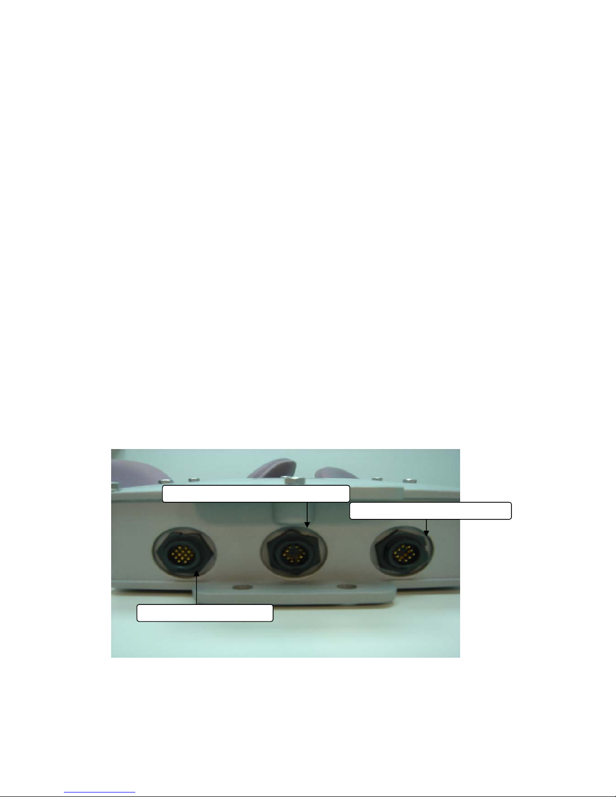
Ethernet & RS-232 Console Connector:
Console Port --- It is used for initial setup and configuration of the device
LAN Port --- It is used for connecting the enclosed PSE for Power Over Ethernet
Ethernet RJ-45 Connector (LAN
)
Ethernet RJ-45 Connector (WAN
)
Console Port Connector
Page 6
6
WAN Port --- It used for connecting to ADSL for ISP
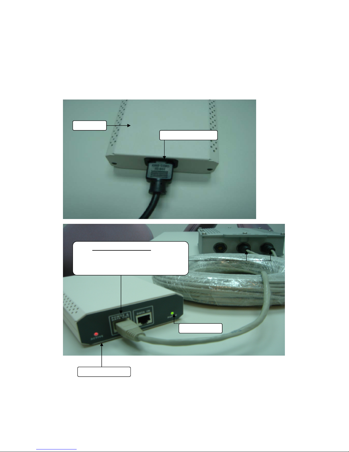
PSE BOX : for Power Over Ethernet (POE)
Power Over Ethernet :
RJ-45 cable connecter PSE BOX
(POWER &DATA OUT port) and
Wireless-G Outdoor AP/Bridge WAN or
LAN E
thernet Port
Power LED
Link Active LED
PSE BOX
A
C Power cable
Page 7

7
Minimum System Requirements
Computers with Windows, Macintosh, or Linux-based operating systems
with an installed Ethernet Adapter
Internet Explorer version 6.0 or Netscape Navigator version 7.0 and above
Introduction
The OUTDOOR BRIDGE covers a large operating distance, providing an
802.11a/b/g outdoor WLAN which enables users to access the Internet or an
organization’s network.
At up to five times the speed of previous wireless devices, you can work faster
and more efficiently, increasing productivity. With the OUTDOOR BRIDGE,
bandwidth-intensive applications like graphics or multimedia will benefit
significantly because large files are able to move across the network quickly.
The OUTDOOR BRIDGE features a die-cast watertight housing and a built-in
lightning protector to protect the access point from harsh environmental
conditions, including extreme variance in temperature. It also includes Power
over Ethernet
(POE) and a unique outdoor remote-mounted design for easy
installation. With two mounting kits, you have the option of either pole or wall
mounting.
The OUTDOOR BRIDGE is suitable for manufacturing plants, industrial sites,
military bases, universities, hotels, airports and golf courses.
The OUTDOOR BRIDGE has Dual Radio functionality for simultaneous AP
and Bridge operations for backhaul applications.
Configurable in four different modes (access point, bridge, multi-point bridge,
and wireless client), the OUTDOOR BRIDGE offers 128-bit encryption, WPA
and 802.1X authentication when used with a RADIUS server, MAC address
access control, and additional security features.
Page 8

8
Features and Benefits
Features the benefit of Robust Outdoor Housing - Designed for harsh
outdoor environments, with die-cast, watertight housing, built-in heater and
temperature sensor
High Performance Dual Radio usage for simultaneous operations of AP and
Bridge for backhaul applications. The dual radio can be configures for AP
and Bridge ; AP and AP ; Bridge and Bridge for various applications
Features the benefits of repeating up to 6 MAC ID for each radio, therefore
ability to repeat up to 12 MAC ID with dual radio functionality for great
coverage and benefits
4 Different Operation modes with WDS (Wireless Distribution System) –
Capable of operating in one of four different operation modes to meet your
wireless networking requirements: access point (AP), Point-to-Point (PtP)
bridge, Point-to-multipoint (PtMP) bridge, Repeater.
Embedded DHCP Server automatically assigns IP addresses to wireless
clients.
Connect networks in different buildings when used in conjunction with
high-gain outdoor antennas.
Easy Installation with PoE.
Compatible with IEEE802.11g standards to provide a wireless data rate of
up to 54Mbps.*
Backward compatible with the 802.11b standard to provide a wireless
data rate of up to 11Mbps with 802.11b devices - that means you can migrate
your system to the 802.11g standard on your own schedule without sacrificing
connectivity.
Better security with WPA and 802.1X- The OUTDOOR BRIDGE can
securely connect to wireless clients on the network using WPA (Wi-Fi
Protected Access) providing a much higher level of security for your data and
communications than has previously been available. In conjunction with a
RADIUS server, 802.1X authentication verifies the identity of would-be clients.
Communicate between IEEE802.11b and IEEE802.11g bands - Optional
configuration allows communication between bands.
Two mounting kits - Gives you the flexibility of either wall or pole outdoor
mounting.
Page 9
9
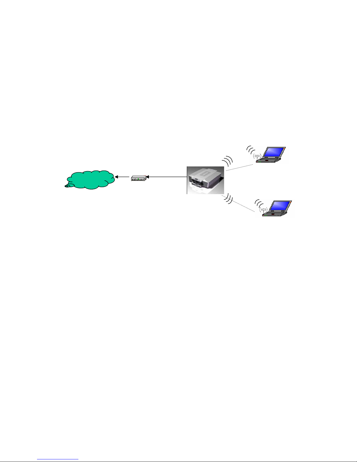
Four Operational Modes
AP Mode
AP Mode
Cable/ADSL Modem
Eth W AN Port
Wireless
Internet
Page 10
10
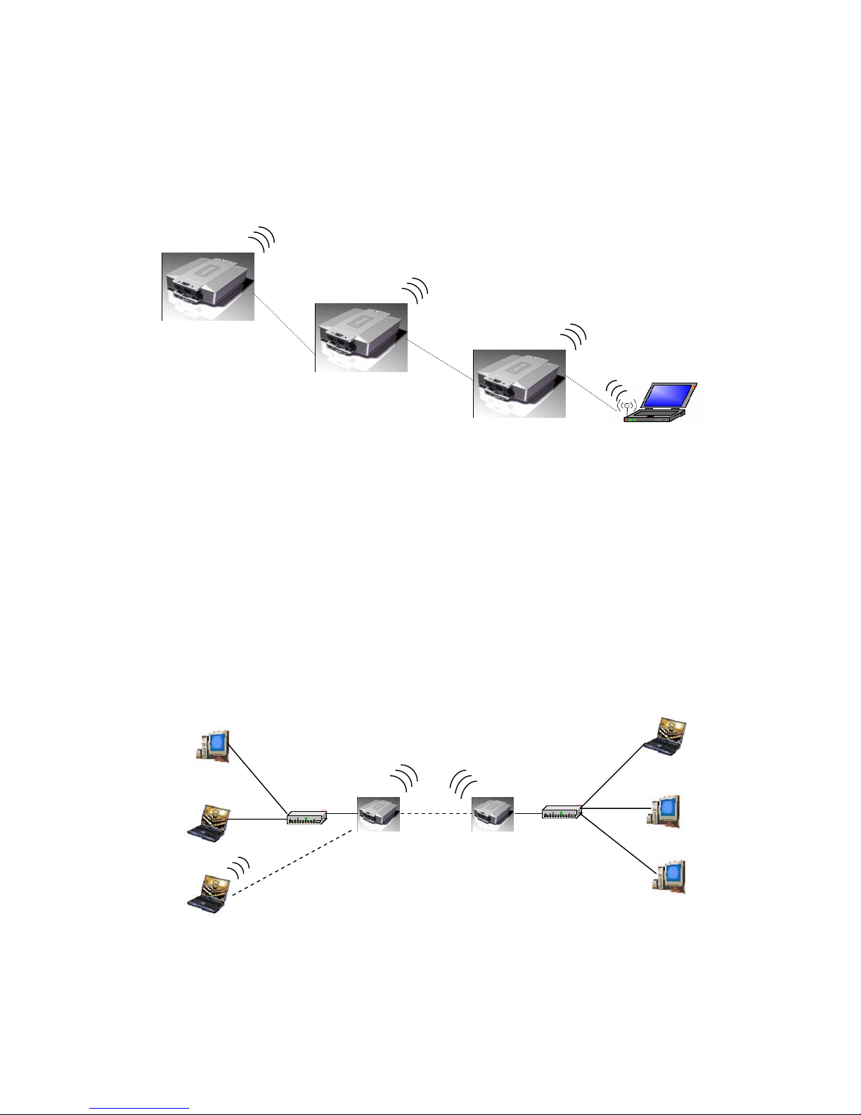
Repeater Mode
Point to Point Mode
Repeater Mode
Access Point
Repeater1
Repeater2
Wireless Client
Point to Point (P2P : Wireless Bridge) Mode
L2 Switch L2 Switch
P2P-1 P2P-2
LAN1
LAN2
Wired Network
Wired Network
Page 11
11
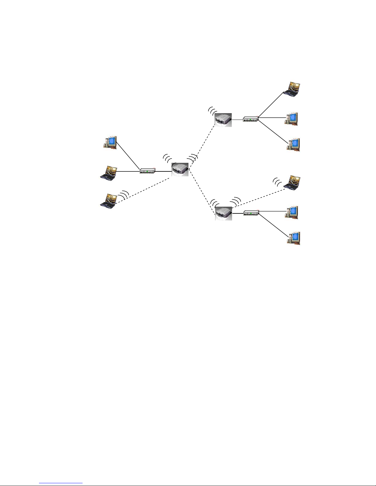
Point to Multi Point Mode
Using the Configuration Menu
To configure the OUTDOOR BRIDGE, use a computer which is connected to
the OUTDOOR BRIDGE with an Ethernet cable (see the
Network Layout
diagram).
First, disable the Access the Internet using a proxy server function. To
disable this function, go to Control Panel > Internet Options > Connections
> LAN Settings and uncheck the enable box.
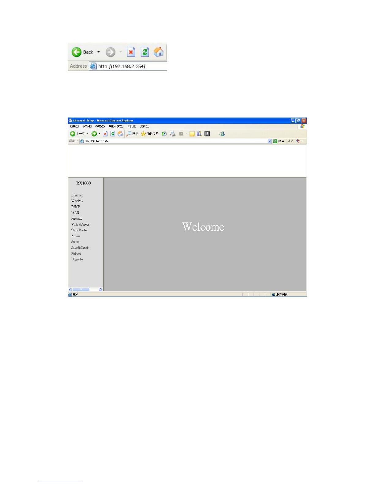
Start your web browser program (Internet Explorer, Netscape Navigator) .
Type the IP address and http port of the OUTDOOR BRIDGE in the address
field
(http://192.168.2.254) and press Enter. Make sure that the IP addresses of the
OUTDOOR BRIDGE and your computer are in the same subnet.
L2 Switch
LAN2
Wired Network
L2 Switch
LAN3
Wired Network
P2P-1
P2P-2
PMP
LAN1
Wired Network
PMP ( Wireless Bridge) Mode
Page 12
12
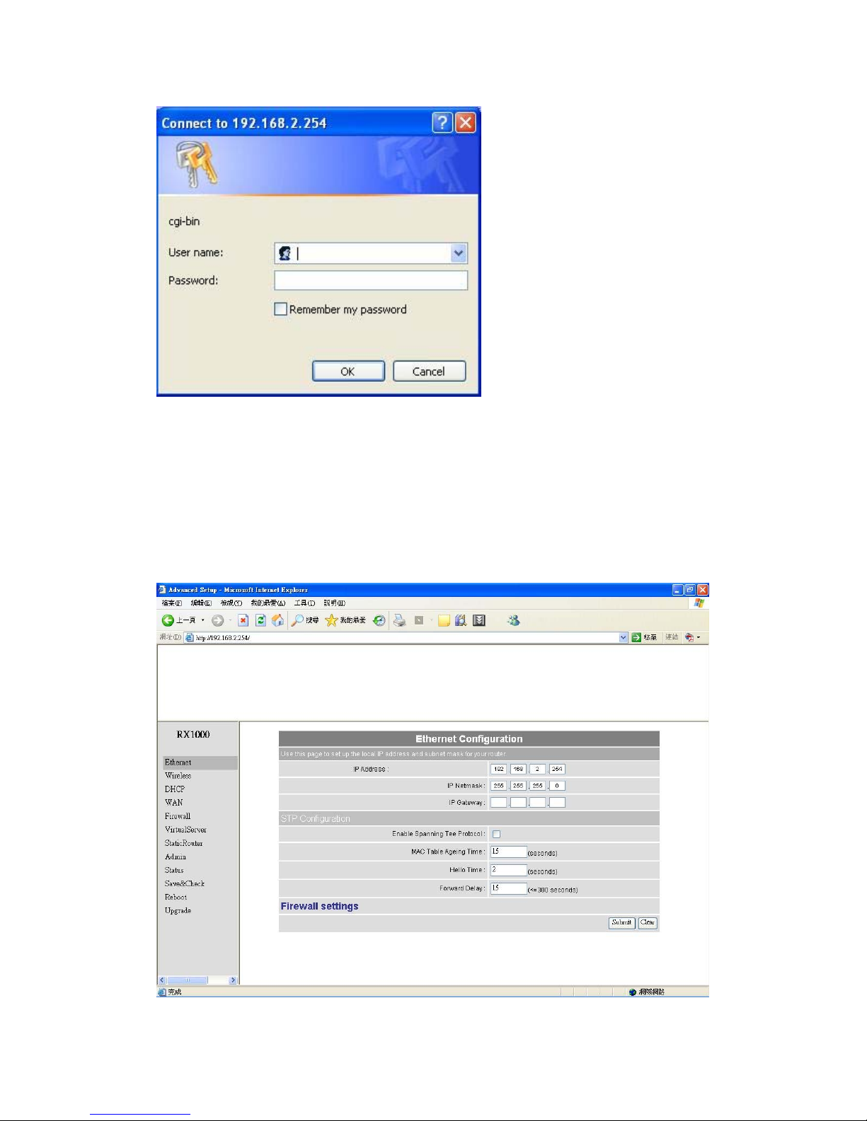
After the connection is established, you will see the user identification window
as shown.
Note: If you have changed the default IP address assigned to the OUTDOOR BRIDGE, make
sure to enter the correct IP address.
If you want to change setting, you will see the user identification window as
shown.
Page 13
13
Type admin in the User Name field
Type default the Password field blank
Click OK
Note: If you have changed the password, make sure to enter the correct password.
Device IP Setting Æ Ethernet
Page 14
14
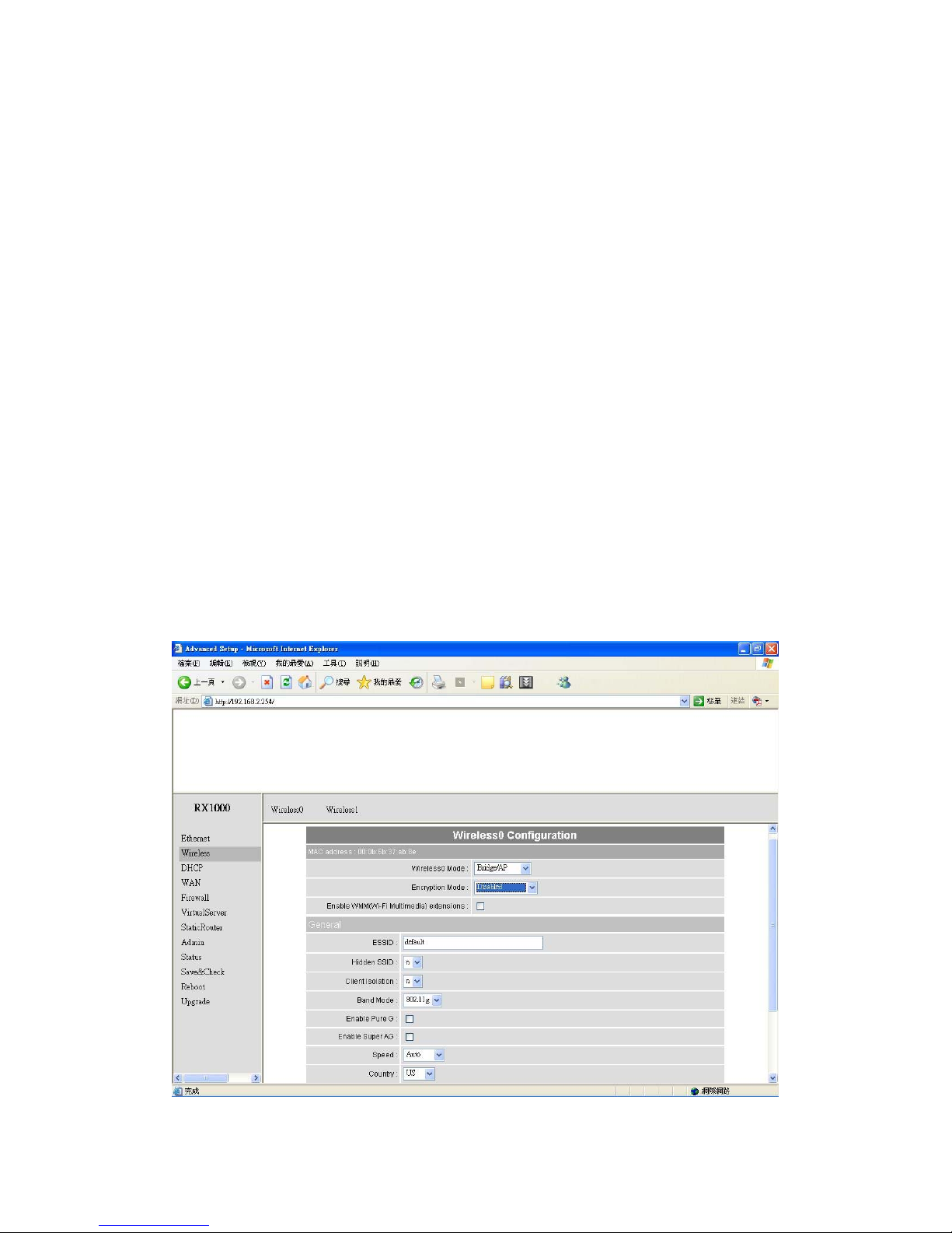
LAN is short for Local Area Network. This is considered your internal network.
These are the IP settings of the LAN interface for the OUTDOOR BRIDGE.
These settings may be referred to as private settings. You may change the
LAN IP address if needed.
IP address: The default IP address is 192.168.2.254. Assign a static IP
address that is within the IP address range of your network.
IP netmask: Enter the subnet mask. All devices in the network must share the
same subnet mask..
IP gateway: Enter the IP address of the gateway in your network.
(Note: If you change any item, click “submit” to store the value. Or click “clear” to
restore previous value. To make settings working click Submit-> Reset->
Restart.)
AP Setting --> Wireless0 or Wireless1
Page 15
15
Page 16
16
Page 17
17
Page 18

18
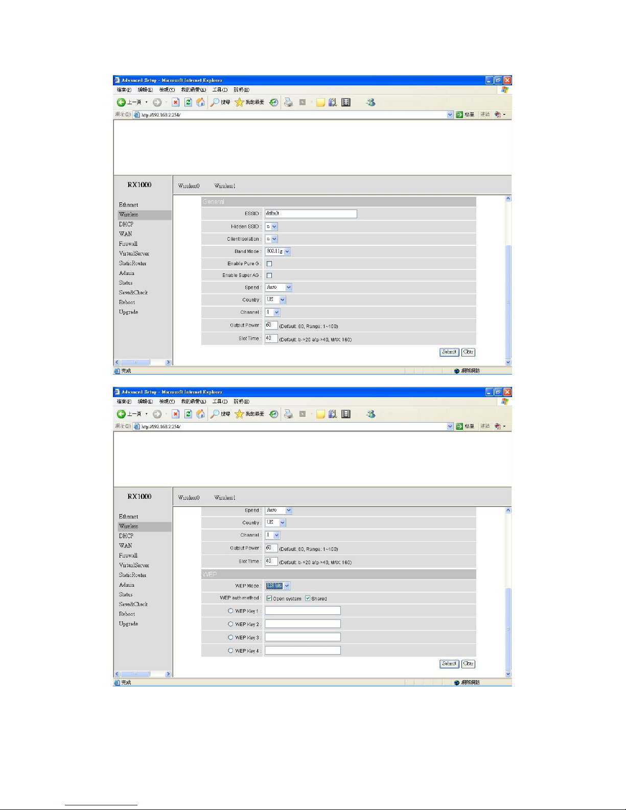
Mode: Bridge/AP Bridge/WDS Routing/AP Routing/WDS or Disable Wireless.
Select Bridge/AP if you want to set wireless in AP mode.
Speed: The speed are Auto, 1Mbps, 2Mbps, 5.5Mbps, 6Mbps, 9Mbps,11Mbps,
12Mbps, 18Mbps, 24Mbps, 36Mbps, 48Mbps, 54Mbps.
Channel: You can select 1 of 3 country setting (US: Channel 1 ~ 11, ETSI:
Channel 1 ~13, Japan: Channel 1 ~ 14 )(Note: Channel 14 only 802.11b
mode). All devices on the network must share the same channel. (Note: The
wireless adapters will automatically scan and match the wireless setting.)
ESSID: Service Set Identifier (SSID) is the name designated for a specific
wireless local area network (WLAN). The SSID’s factory default setting is
default. The SSID can be easily changed to connect to an existing wireless
network or to establish a new wireless network.
Preamble: Pull down select “long” or “short”.
hidden SSID: Enable or Disable SSID broadcast. Pull down select “y” Disable
SSID broadcast or “n” Enable SSID broadcast. Disable this feature broadcasts
the SSID across the network.
Client Isolation: Pull down “y” isolation or “n” none isolation
Encryption
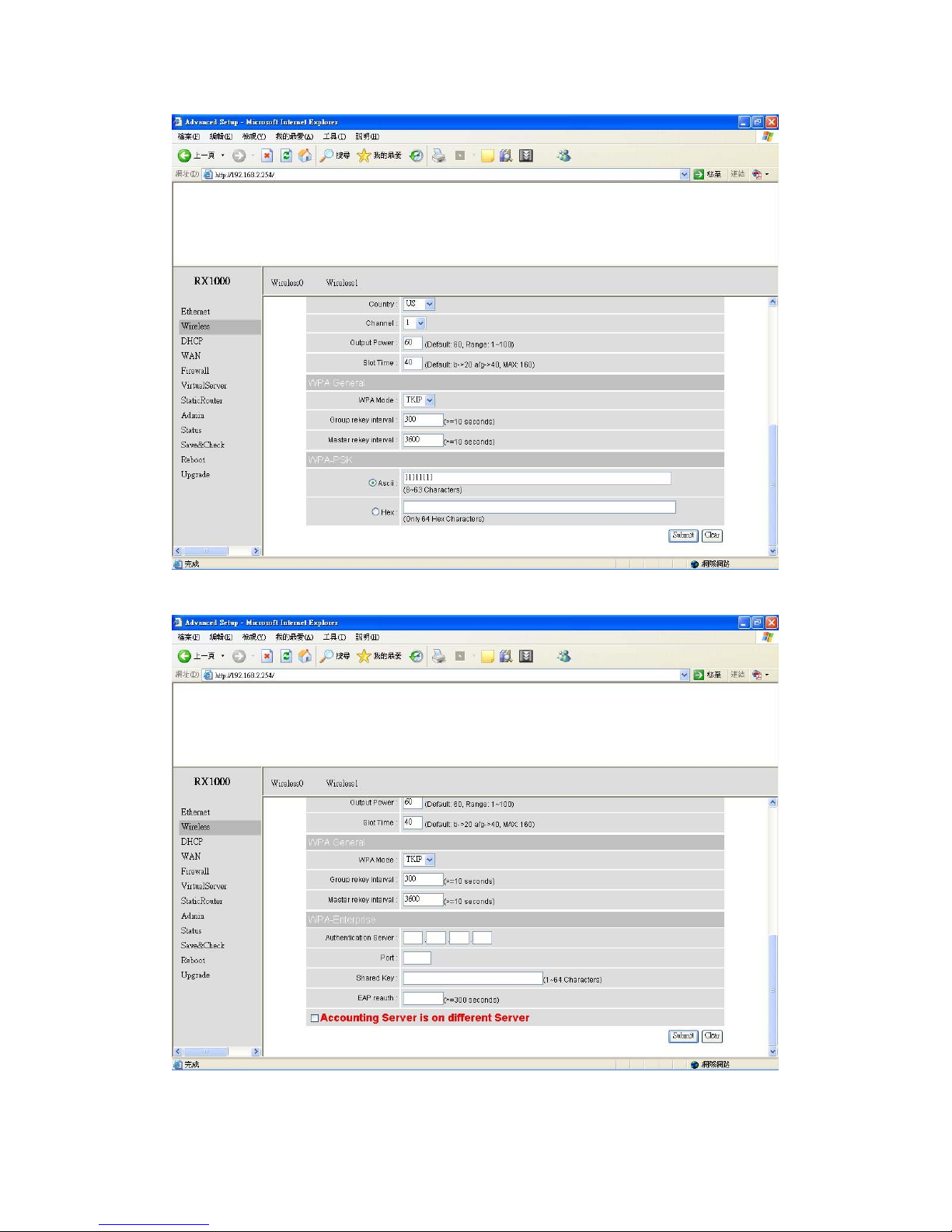
The OUTDOOR BRIDGE has the newest, strongest and most advanced
security features available today. When used with other 802.11 WPA (Wi-Fi
Protected Access) compatible products in a network with a RADIUS server,
the security features include:
WPA & 802.1x represent the first line of defense against network intrusion. In
the authentication process the RADIUS server verifies the identity of the client
attempting to connect to the network. Unfamiliar clients will be denied access.
EAP(Extensible Authentication Protocol) is available through the Windows XP
Operating System. You will need to use the same type of EAP protocol on all
the devices in your network when using the 802.1x feature.
Page 19

19
WPA (Wi-Fi Protected Access) authorizes and identifies users based on a
secret key that changes automatically at regular intervals. WPA uses TKIP
(Temporal Key Integrity Protocol) to change the temporal key every 10,000
packets (a packet is a kind of message transmitted over a network.) This
ensures much greater security than the standard WEP security. (By contrast,
the previous WEP encryption implementations required the keys to be
changed manually.)
WPA-PSK allows home users that will not incorporate a RADIUS server in
their network, access to WPA security. Utilizing the Pre-Shared Key mode of
WPA, the OUTDOOR BRIDGE will obtain a new security key every time it
connects to the 802.11 network. You only need to input your encryption
information once in the configuration menu. No longer will you have to
manually input a new WEP key frequently to ensure security. With the
OUTDOOR BRIDGE and WPA-PSK, you will automatically receive a new key
every time you connect, vastly increasing the safety of your communication.
Set Encryption to Open System
WEP auth method: Select Open System to communicate the key across the
network.
WEP mode: Select 64, 128 bits.
Key Type: 64 bit support WEP password 10 bit HEX(Hexadecimal digits consist
or the numbers 0-9 and the letters A-F) code. 128 bit support WEP password 26
bit HEX code.( Note :Currently version does not support ASIC code.)
Valid Key: Select one of the keys in the Key table to be the active key.
Key Table: Enter up to four encryption keys here.
Set Encryption to Shared Key
WEP auth method: Select Shared Key to communicate the key across the
network.
WEP mode: Select 64, 128 bits.
Key Type: 64 bit support WEP password 10 bit HEX(Hexadecimal digits consist
or the numbers 0-9 and the letters A-F)
code. 128 bit support WEP password 26
bit HEX code.( Note :Currently version does not support ASIC code.)
Valid Key: Select one of the keys in the Key table to be the active key.
Key Table: Enter up to four encryption keys here.
Page 20

20
Set Encryption to Open System/Shared Key
WEP auth method: Select Open System and Shared Key to communicate
the key across the network.
WEP mode: Select 64, 128 bits.
Key Type: 64 bit support WEP password 10 bit HEX(Hexadecimal digits consist
or the numbers 0-9 and the letters A-F)
code. 128 bit support WEP password 26
bit HEX code.( Note :Currently version does not support ASIC code.)
Valid Key: Select one of the keys in the Key table to be the active key.
Key Table: Enter up to four encryption keys here
Set Encryption to WPA-PSK
Authentication: WEP auth method select dis then select WPA and check
WPA-PSK
PSK: Enter a passphrase that will be shared by all devices using WPA-PSK on
the network.
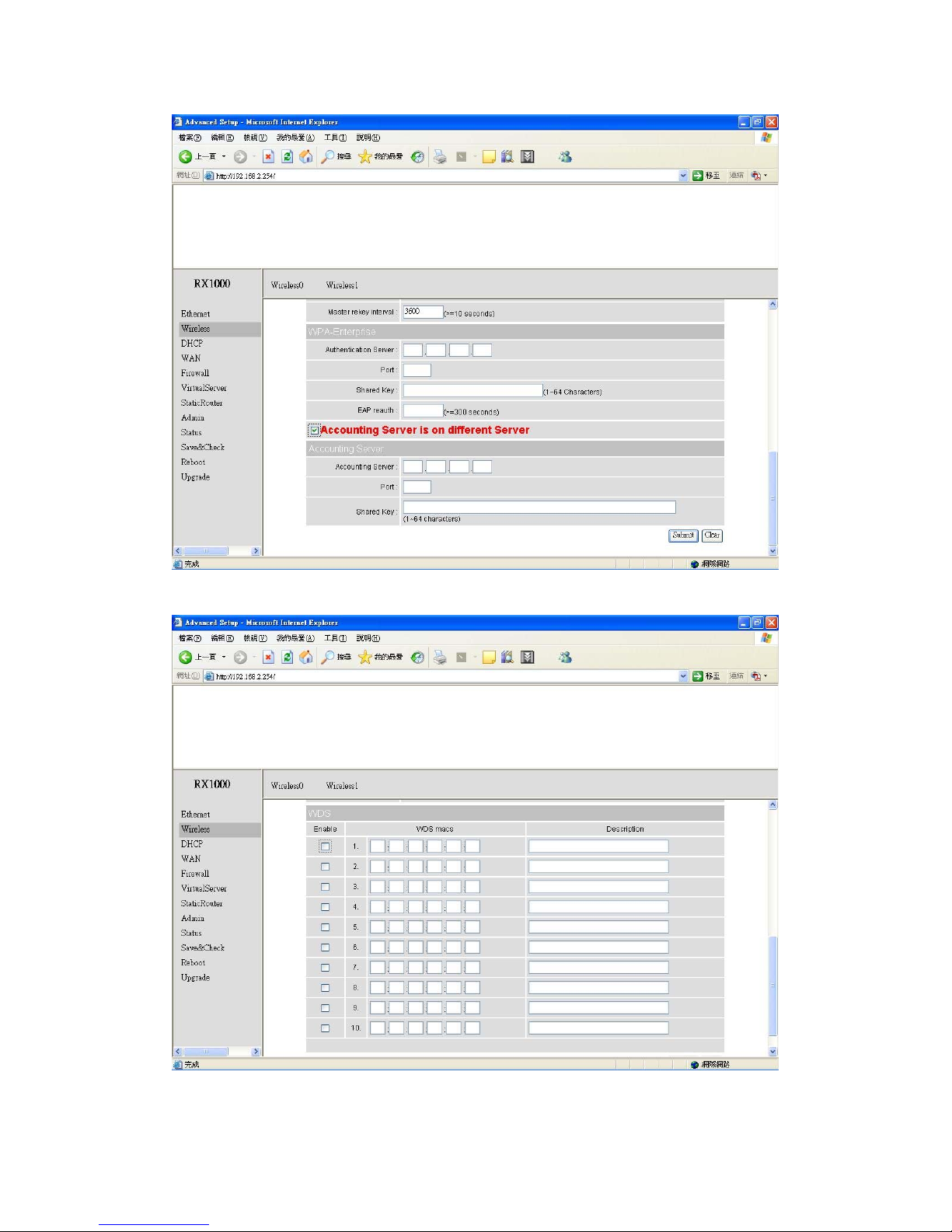
Set Encryption to WPA-Enterprise(802.1x)
Authentication: WEP auth method select dis then select WPA and
WPA-Enterprise (802.1x)
RADIUS Server: Enter the IP address of the RADIUS server.
Authentic Port: 1812 is the port number dedicated to the authentication
function of the RADIUS server.
Accounting: Enter the IP address of the RADIUS server and port number
dedicated to RADIUS accounting. The RADIUS server uses accounting to
keep track of user login sessions.
Radius Key: Enter the secret Key that is required of all devices to
communicate with the RADIUS server.
(Note: If you change any item, click “submit” to store the value. Or click “clear” to
restore previous value. To make settings working click Submit-> Reset->
Restart.)
Page 21
21
Point to Point Mode Setting Æ Wireless0 or Wireless1
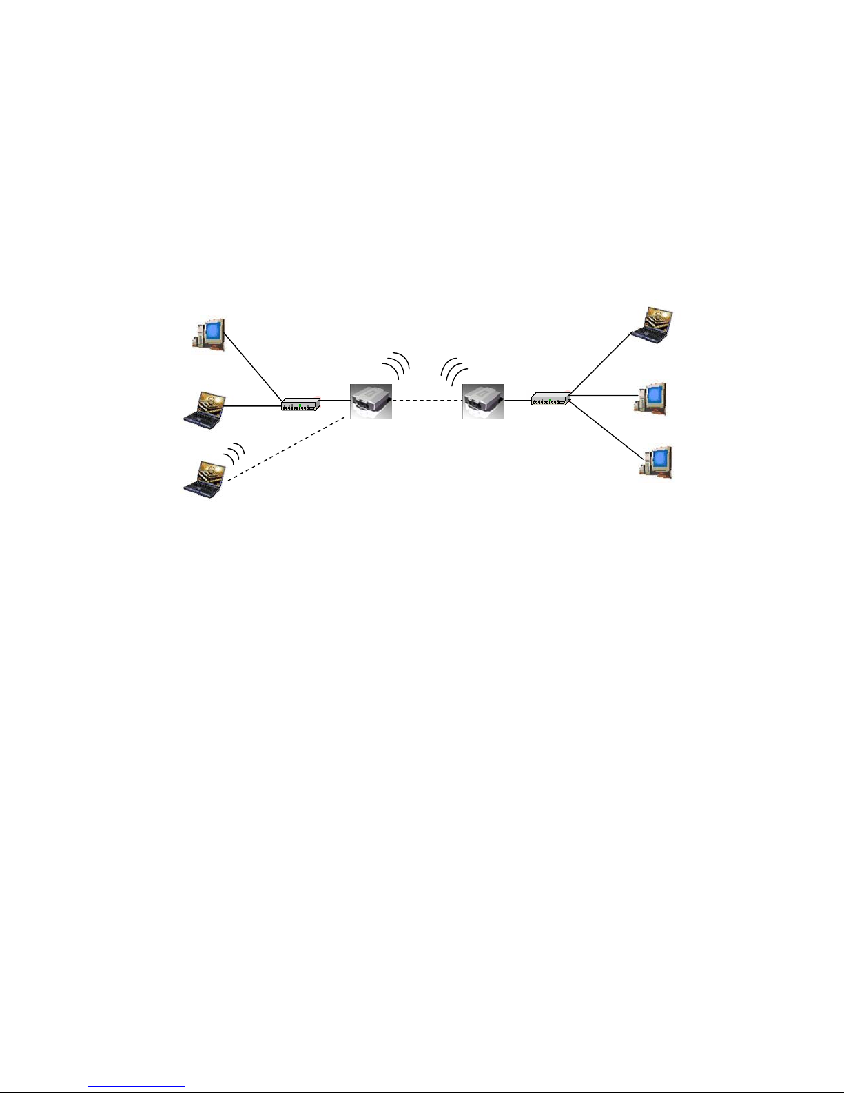
PtP mode setting is like AP mode setting, but encryption only WEP encryption
method can select. When wireless0 or wireless1 in PtP mode will also do AP
function, suggest disable SSID broadcast(Pull down select “y” in hidden SSID to
disable SSID broadcast) and set WEP encryption.
e.g.
P2P-1 Wireless0 Mac: 00.01.02.03.04.05 Wireless1 Mac: 00.01.02.03.04.06
P2P-2 Wireless0 Mac: 00.01.02.03.04.07 Wireless1 Mac: 00.01.02.03.04.08
Set P2P-1 Wireless 1 in AP/Bridge Mode, and type P2P-2 Wireless1 Mac:
00.01.02.03.04.08 in WDS macs fields. Then set WEP encryption, and disable WPA
encryption. Pull down select “y” in hidden SSID to disable SSID broadcast.
Set P2P-2 Wire less1 in AP/Bridge Mode, and type P2P-1 Wireless1 Mac:
00.01.02.03.04.06 in WDS macs fields. Then set channel the same as P2P-1
Wireless1.Set WEP encryption the same as P2P-1 Wireless1.Dsiable P2P-2 Wireless1
WPA encryption. Pull down select “y” in hidden SSID to disable SSID broadcast.
Point to Point (P2P : Wireless Bridge) Mode
L2 Switch L2 Switch
P2P-1 P2P-2
LAN1
LAN2
Wired Network
Wired Network
Page 22
22
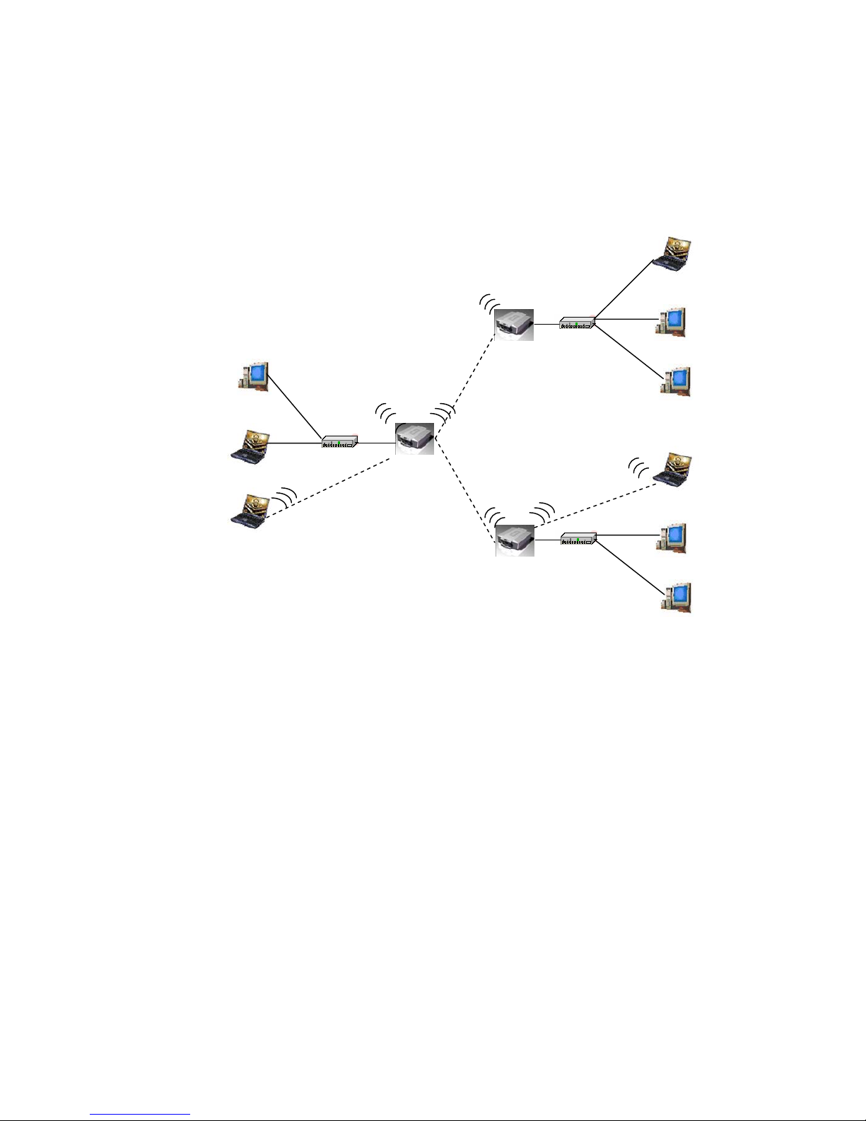
Point to Multi Point Mode Setting Æ Wireless0 or
Wireless1
PtMP mode setting is like AP mode setting, but encryption only WEP
encryption method can select. When wireless0 or wireless1 in PtMP mode will
also do AP function, suggest disable SSID broadcast(Pull down select “y” in
hidden SSID to disable SSID broadcast) and set WEP encryption.
e.g PMP Wireless0 Mac: 00.01.02.03.04.05 Wireless1 Mac: 00.01.02.03.04.06
P2P-1 Wireless0 Mac: 00.01.02.03.04.07 Wireless1 Mac: 00.01.02.03.04.08
P2P-2 Wireless0 Mac: 00.01.02.03.04.09 Wireless1 Mac: 00.01.02.03.04.0A
Set PMP Wireless1 in AP/Bridge Mode, and type P2P-1 Wireless1 Mac:
00.01.02.03.04.08 and P2P-2 Wireless1 Mac: 00.01.02.03.04.0A in WDS macs fields.
Then set WEP encryption, and disable WPA encryption. Pull down select “y” in
hidden SSID to disable SSID broadcast.
Set P2P-1 Wire less1 in AP/Bridge Mode, and type PMP Wireless1 Mac:
00.01.02.03.04.06 in WDS macs fields. Then set channel the same as PMP
Wireless1.Set WEP encryption the same as PMP Wireless1.Dsiable P2P-1 Wireless1
L2 Switch
LAN2
Wired Network
L2 Switch
LAN3
Wired Network
P2P-1
P2P-2
PMP
LAN1
Wired Network
PMP ( Wireless Bridge) Mode
Page 23

23
WPA encryption. Pull down select “y” in hidden SSID to disable SSID broadcast.
Set P2P-2 Wire less1 in AP/Bridge Mode, and type PMP Wireless1 Mac:
00.01.02.03.04.06 in WDS macs fields. Then set channel the same as PMP
Wireless1.Set WEP encryption the same as PMP Wireless1.Dsiable P2P-2 Wireless1
WPA encryption. Pull down select “y” in hidden SSID to disable SSID broadcast.
Page 24
24
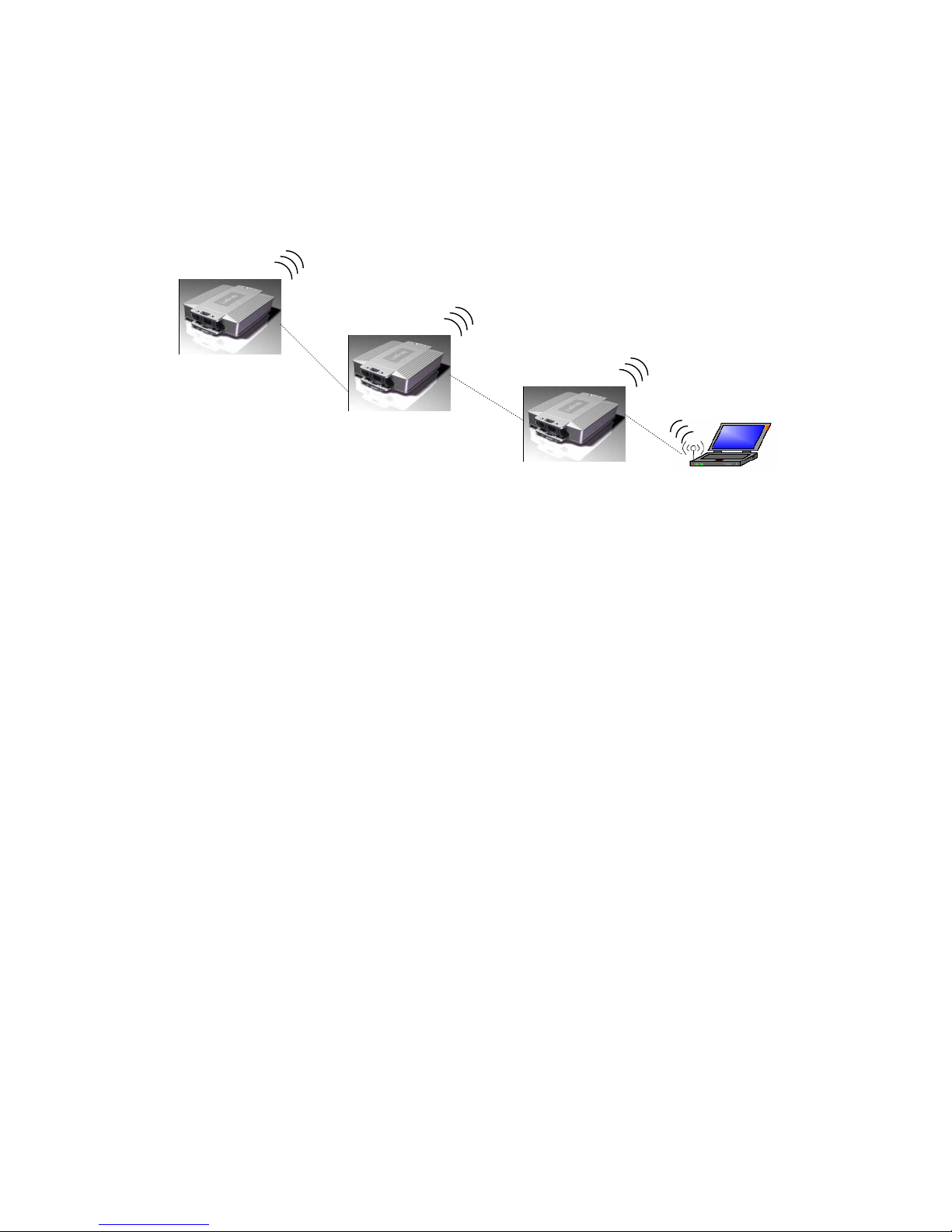
Repeater Mode Setting Æ Wireless0 or Wireless1
Repeater mode setting is like AP mode setting, but encryption only WEP
encryption method can select.
e.g AP Wireless0 Mac: 00.01.02.03.04.05 Wireless1 Mac: 00.01.02.03.04.06
Repeater1 Wireless0 Mac: 00.01.02.03.04.07 Wireless1 Mac: 00.01.02.03.04.08
Repeater2 Wireless0 Mac: 00.01.02.03.04.09 Wireless1 Mac: 00.01.02.03.04.0A
Set AP Wireless1 in AP/Bridge Mode, and type Repeater1 Wireless0 Mac:
00.01.02.03.04.07 in WDS macs fields.Then set WEP encryption, and disable WPA
encryption.
Set Repeater1 Wireless0 in AP/Bridge Mode, and type AP Wireless1 Mac:
00.01.02.03.04.06 in WDS macs fields. Then set channel the same as AP
Wireless1.Set WEP encryption the same as AP Wireless1.Dsiable Repeater1 Wireless0
WPA encryption. Set Repeater1 Wireless1 in AP/Bridge Mode, and type Repeater2
Wireless0 Mac: 00.01.02.03.04.09 in WDS macs fields. Set WEP encryption the same
as AP Wireless1.Dsiable Repeater1 Wireless1 WPA encryption.
Set Repeater2 Wireless0 in AP/Bridge Mode, and type Repeater1 Wireless1 Mac:
00.01.02.03.04.08 in WDS macs fields. Then set channel the same as Repeater1
Wireless1.Set WEP encryption the same as AP Wireless1.Dsiable Repeater2 Wireless0
WPA encryption.
Repeater Mode
Access Point
Repeater1
Repeater2
Wireless Client
Page 25

25
Dual Radio Setting For Simultaneous Operation
AP and Bridge
e.g. Wireless0 do AP Setting as page 11 and Wireless1 do Bridge setting as
page 17 (PtP Setting) or page 18 (PtMP setting). Wireless0 and Wireless1 can
do different Setting such as different channel and different Encryption
AP and AP
Wireless0 and Wireless1 do AP Setting as page 11. Wireless0 and Wireless1
can do different Setting such as different channel and different Encryption.
Bridge and Bridge
Wireless0 and Wireless1 do Bridge setting as page 17 (PtP Setting) or page
18 (PtMP setting). Wireless0 and Wireless1 can do different Setting such as
different channel and different Encryption
Page 26
26
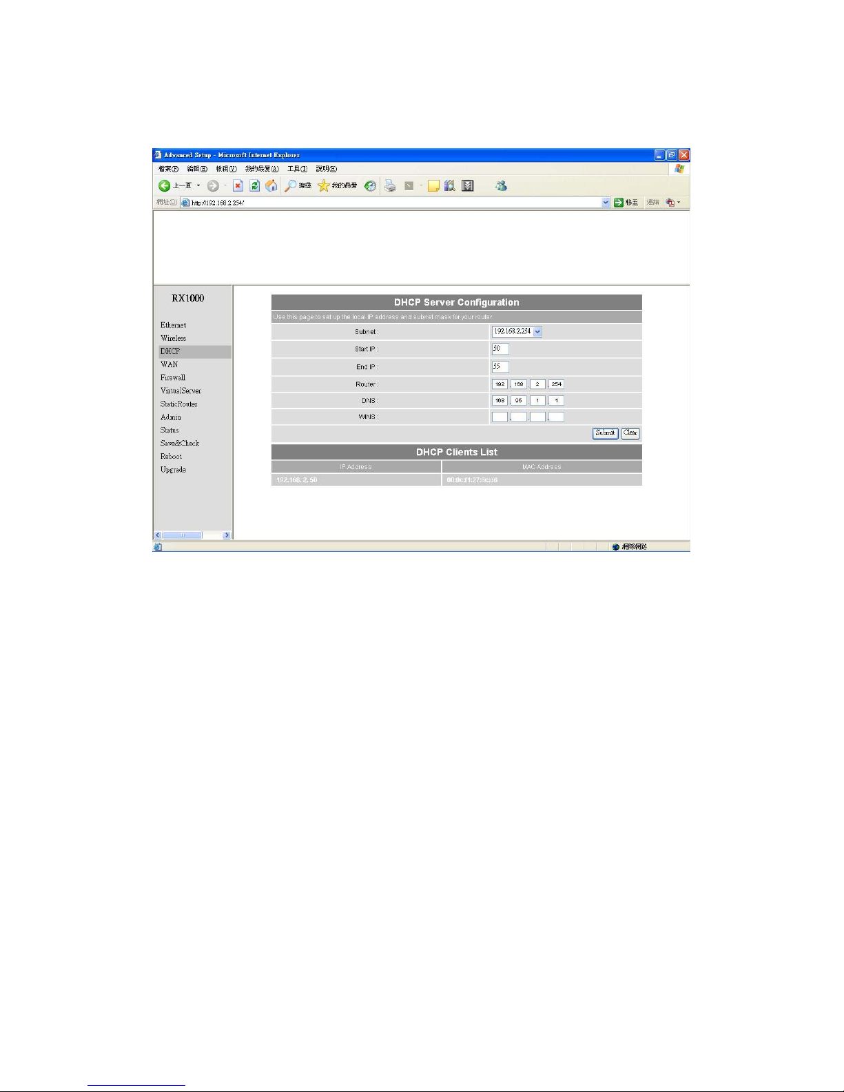
DHCP Server Setting Æ DHCP
DHCP Server Control: Dynamic Host Configuration Protocol assigns
dynamic IP addresses to devices on the network. This protocol simplifies
network management and allows new wireless devices to receive IP
addresses automatically without the need to manually assign new IP
addresses.
Select Subnet on device IP(Such as 192.168.2.254) to allow the OUTDOOR
BRIDGE to function as a DHCP server.
start IP: Input the first IP address available for assignment in your network.
end IP: Input the end IP address available for assignment in your network.
router: Input device IP
dns: Input your ISP DNS.
Page 27

27
wins: Input wins server IP
DHCP Clients show the client IP and client MAC setting.
(e.g. If your device ip is 192.168.2.254, then start ip is 10 and end ip is 100.
System will asign ip from 192.168.2.10 to 192.168.2.100 to client.)
(Note: If you change any item, click “submit” to store the value. Or click “clear” to
restore previous value. To make settings working click Submit-> Reset->
Restart.)
Page 28
28
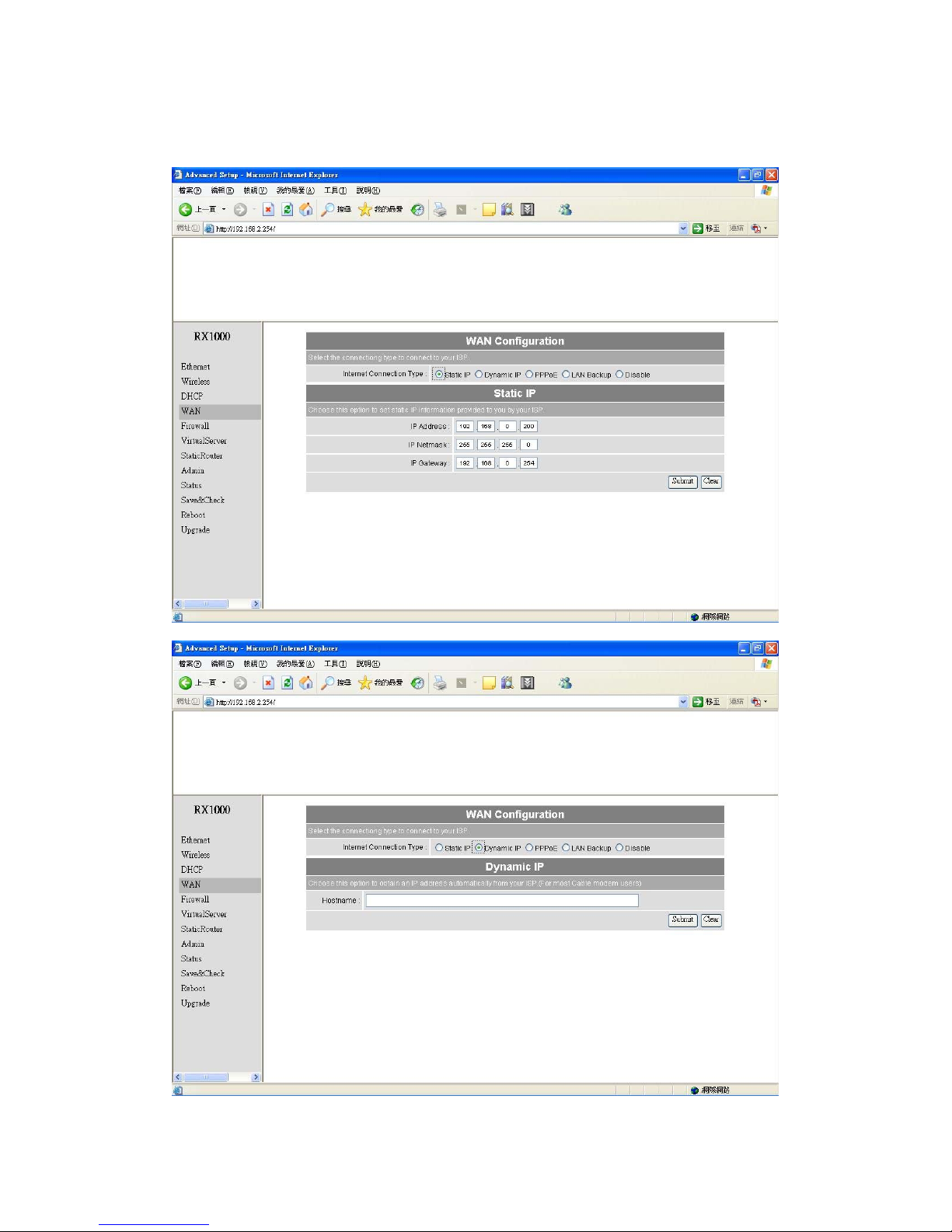
WAN Setting Æ WAN
Page 29
29
Page 30
30
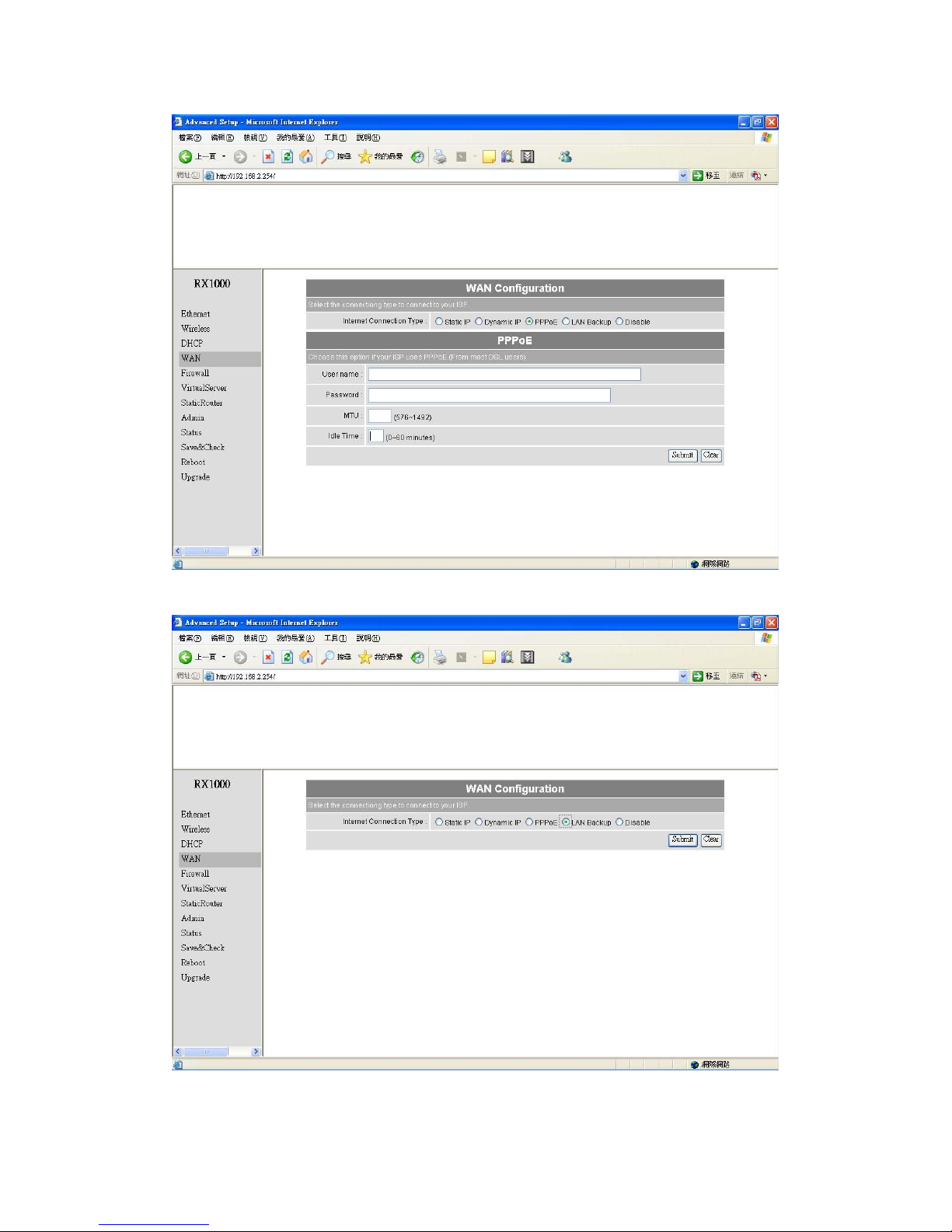
To select the connection type for WAN PORT, you can choose any of the following
Mode:
• For static IP, please click Static IP and type IP address, IP netmask, IP
gateway.
• For dynamic IP address, please click the Dynamic IP and type Hostname
• For xDSL and using PPPoE to connect to Internet, please click PPPoE
and type username and password.
• For LAN Backup
• For Disable WAN Port, please click Disable.
(Note: If you change any item, click “submit” to store the value. Or click “clear” to
restore previous value. To make settings working click Submit-> Reset->
Restart.)
WAN Status Æ WAN Status
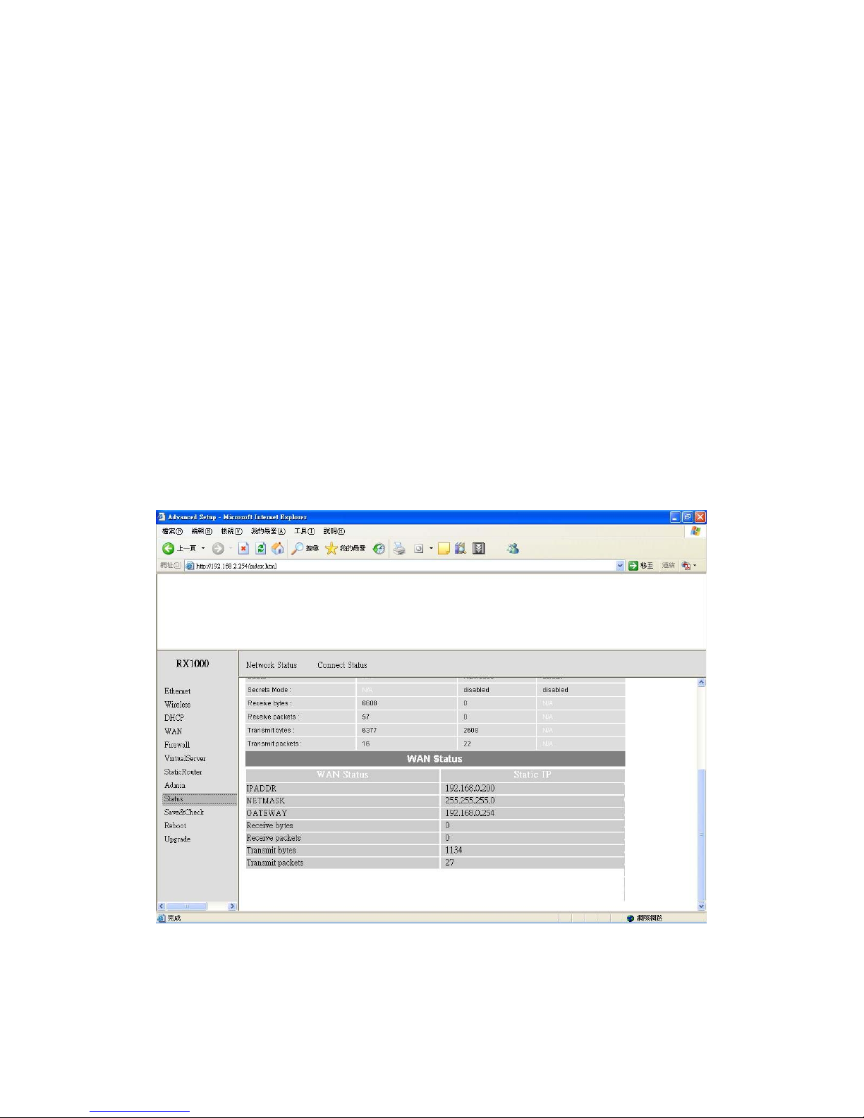
When WAN setting is Static IP click Status/Network Status will show current IP
status. You can click renew or release to renew or release IP at Dynamic IP setting,
Page 31
31
and click disconnect or connect to disconnect or connect your ISP at PPPoE setting.
Admin setting Æ Admin
Page 32

32
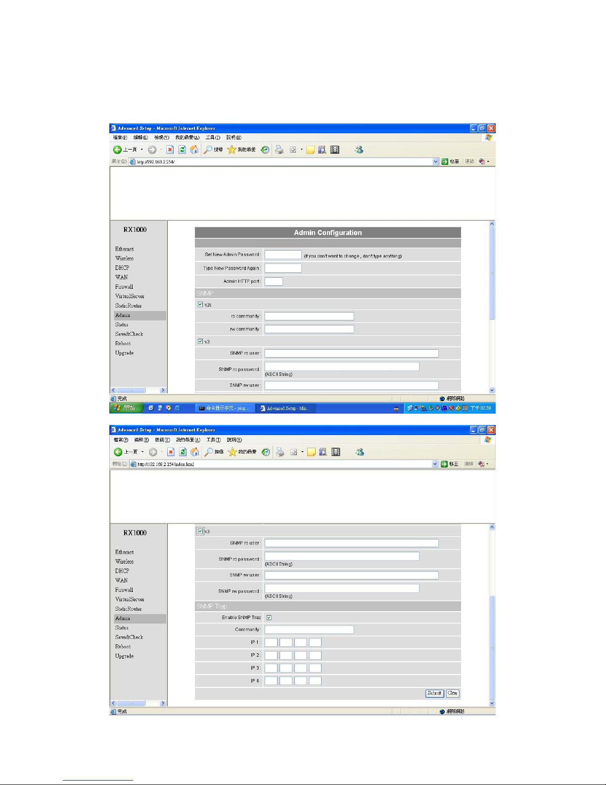
You can change login password (default password is “default”), SNMP user
name and password, and SNMP Trap setting here.
(Note: If you change any item, click “submit” to store the value. Or click “clear” to
restore previous value. To make settings working click Submit-> Reset->
Restart.)
Page 33
33
Firewall setting Æ Firewall
Page 34
34
Page 35
35
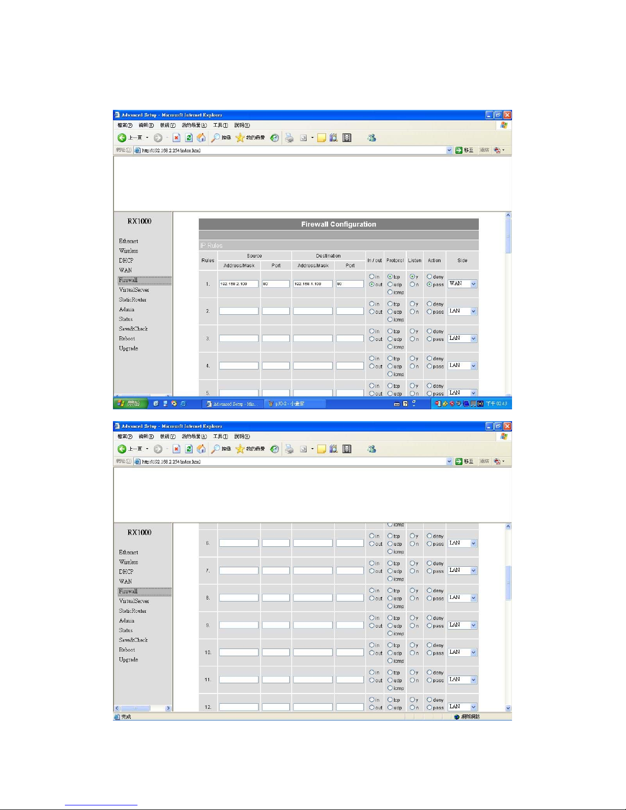
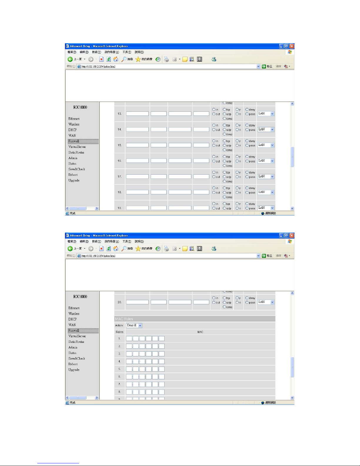
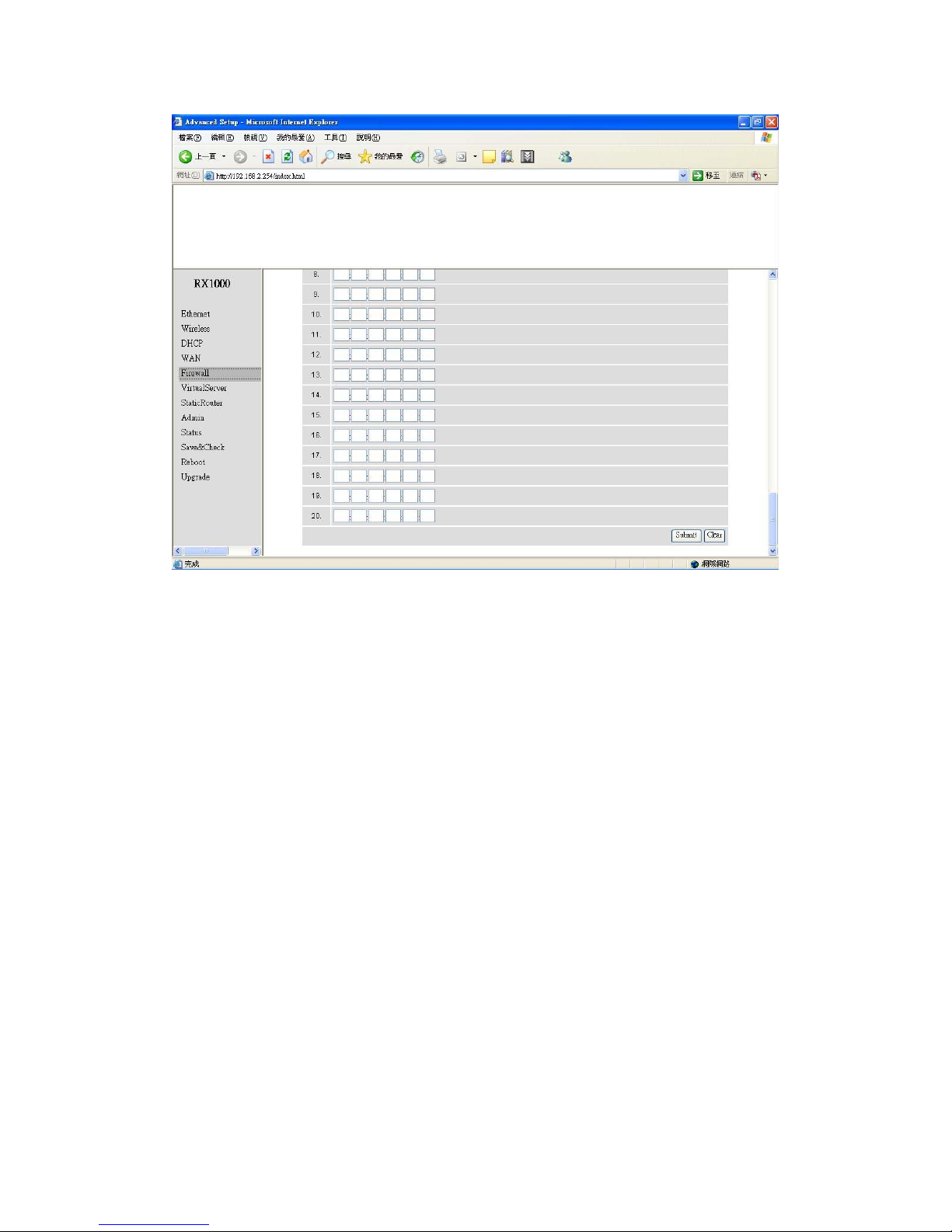
In Firewall IP Rules fields you can define 20 IP rules to deny or pass
networking which fit the rules.
In Firewall MAC Rules fields you can control 20 MACs which can pass connect
to system or deny from system.
(Note: If you change any item, click “submit” to store the value. Or click “clear” to
restore previous value. To make settings working click Submit-> Reset->
Restart.)
Page 36
36
Virtual Server setting Æ Virtual Server
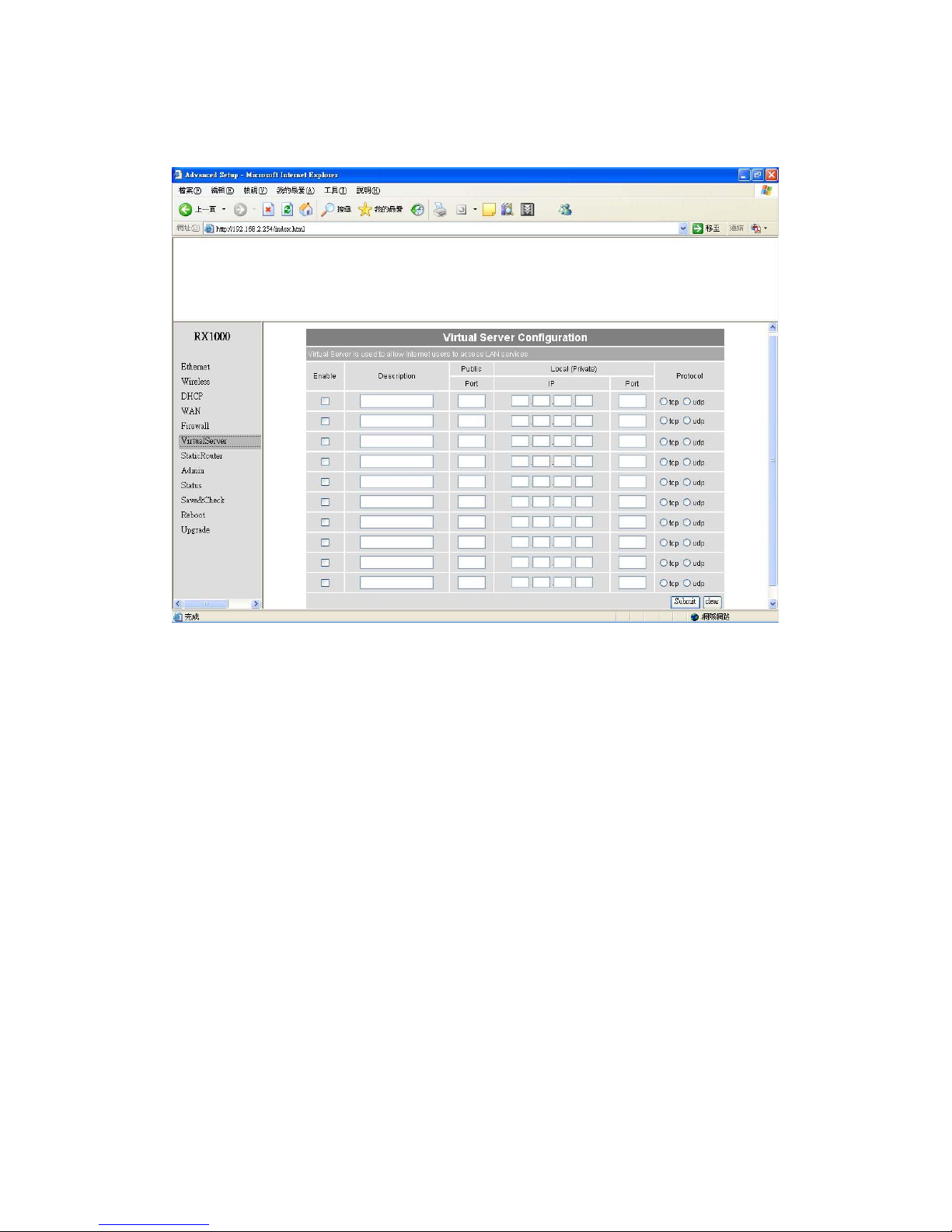
You can define 10 groups Virtual Server here.
e.g. If you build a Server at local PC(client) and Wireless-G Outdoor AP/Bridge
is connect to internet have a real IP. Check Enable the rule in Virtual Server
and type Description, then key-in local PC’s IP in Local IP fields and port(use
by the Server) in Local Port and select protocol (use by the Server). After finish
those setting click Submit-> Reset-> Restart restart system to make settings
work. The Server build at local PC will work in internet.
Page 37
37
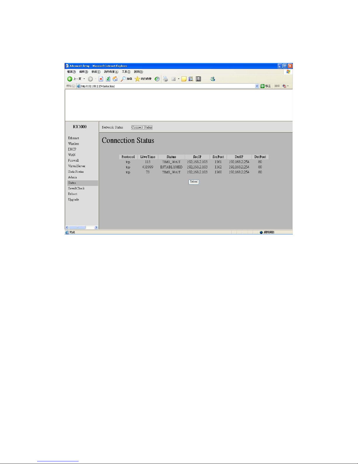
Connection Status
It will show the device connection status.
Page 38

38
Firmware upgrade Æ Upgrade
Step 1 : Set your PC IP (192.168.2.X), and close PC’s firewall.
Step 2 : Open a TFTP server on your PC and put the firmware in the same direct.
Step 3 : Click on the Upgrade tab and then the main screen enter the PC IP address in
the “tftp server :"field section 192.168.2.X , and the second option “file name"
please key in the firmware file name. Then click Download and reset. It may take
a up to 2 min for the upgrade to complete.
Page 39
39
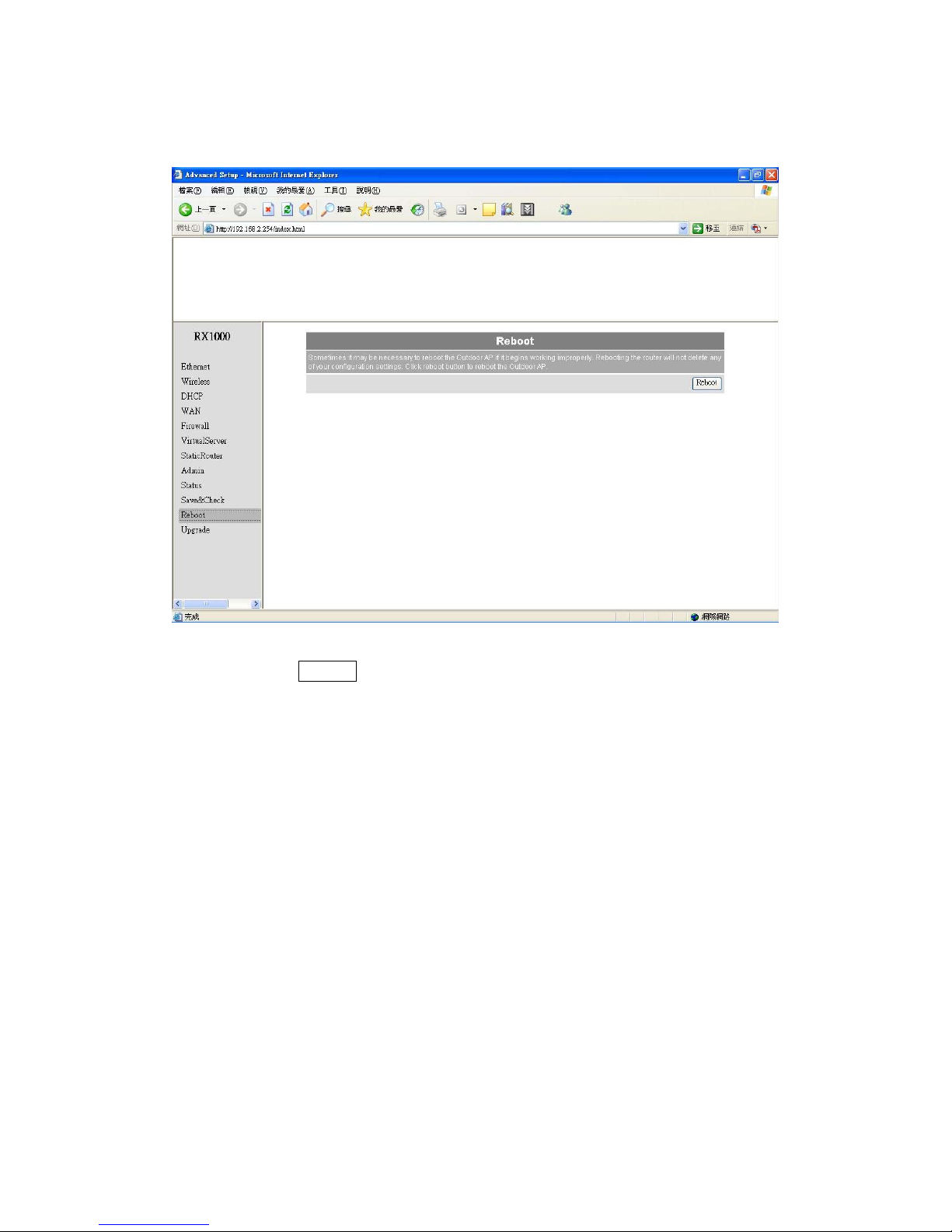
Reboot System Æ Reboot
Click Reboot Æ Restart will store settings and restart system.
Page 40
40
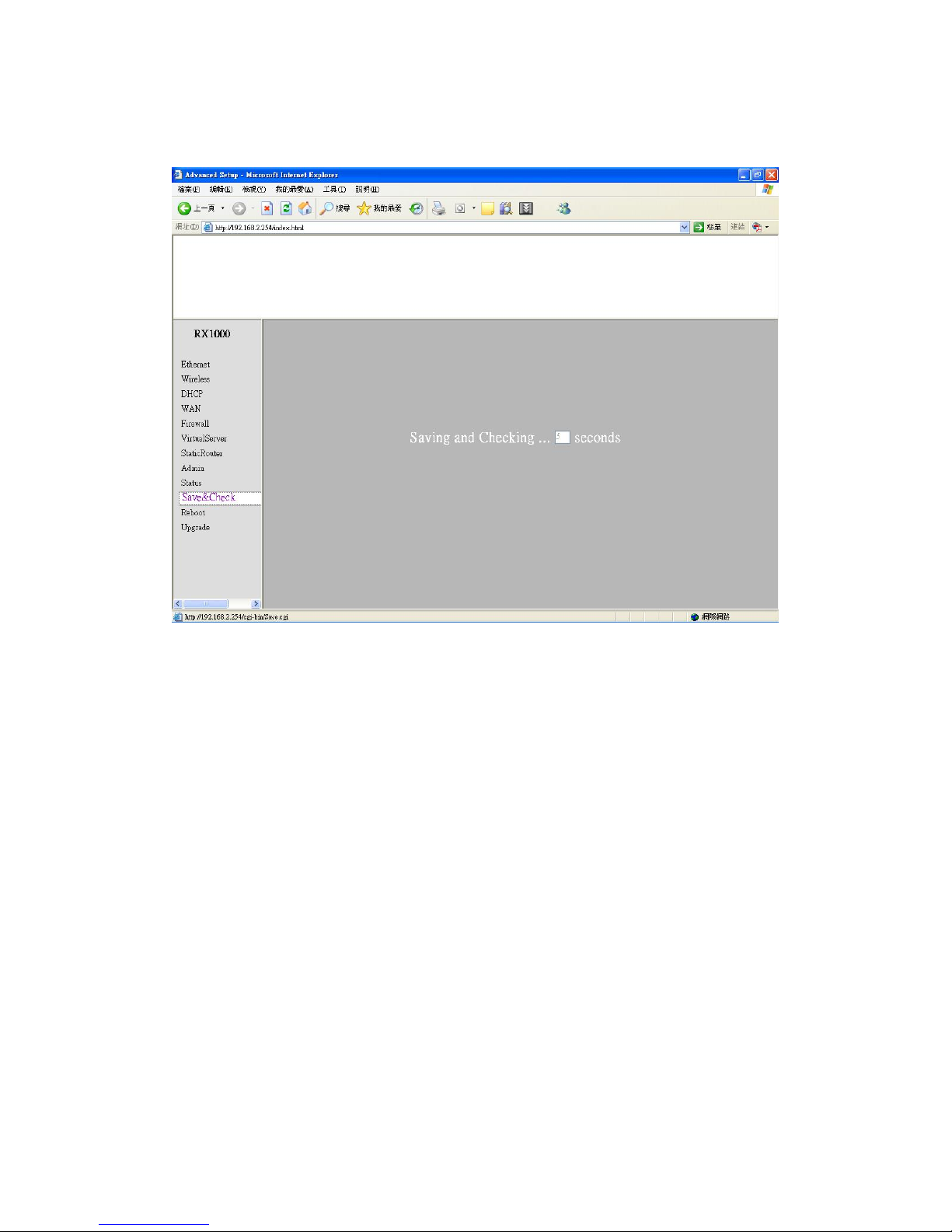
Save & Check System Æ Save & Check
Click Save & Check Æ It will store settings and check system.
 Loading...