

Page 1
AP-952X
Industrial W all-mounted Wireless-N/BG AP/Bridge
User's Manual
Release Date : 2010/07/23
Release Version : 0.0.1
Page 2

Table of Contents
Chapter 1. Before You Start ..............................................................................................1
1.1 Preface......................................................................................................................................1
1.2 Package Contents.....................................................................................................................1
Chapter 2. System Overview.............................................................................................2
2.1 Introduction of AP-952X ............................................................................................................2
2.2 Specification ............................................................................................................................3
Chapter 3. Base Installations............................................................................................6
3.1 Installations...............................................................................................................................6
3.1.1 System Requirements.......................................................................................................6
3.1.2 Panel Function Descriptions..............................................................................................6
3.1.3 Hardware Installation.........................................................................................................8
3.2 Software Configuration..............................................................................................................9
3.2.1 Getting Start...................................................................................................................... 9
3.2.2 Quick Configuration.........................................................................................................11
Chapter 4. AP Mode Configuration.................................................................................13
4.1 Connect AP-952X to the Wired Local Network......................................................................14
4.1.1 Network Requirement......................................................................................................14
4.1.2 Configure LAN Port .........................................................................................................15
4.2 Create Your Wireless Network ................................................................................................17
4.2.1 Configure Wireless General Setup..................................................................................17
4.2.2 Configure Wireless Advanced Setup............................................................................... 19
4.2.3 Create Virtual AP.............................................................................................................22
4.2.3.1 Configure Virtual AP ................................................................................................24
4.2.3.2 Block Wireless Clients ...........................................................................................30
4.2.3.3 Monitor Associated Wireless Clients........................................................................31
4.3 Expand Your Wireless Network...............................................................................................32
4.3.1 Create WDS Link.............................................................................................................32
4.3.2 View WDS Link Status..................................................................................................33
4.4 Manage the System ................................................................................................................34
4.4.1 Configure System Time...................................................................................................34
4.4.2 Configure Management...................................................................................................35
4.4.3 Configure SNMP..............................................................................................................37
4.4.4 Backup / Restore and Reset to Factory...........................................................................38
4.4.5 Firmware Upgrade...........................................................................................................39
4.4.6 Network Utility .................................................................................................................40
4.4.7 Reboot.............................................................................................................................41
4.5 Observer the Status.................................................................................................................42
Page 3

4.5.1 Overview .........................................................................................................................42
4.5.2 Extra Info.........................................................................................................................43
4.5.3 Event Log........................................................................................................................45
Chapter 5. WDS Mode Configuration.............................................................................46
5.1 Connect AP-952X to the Wired Local Network........................................................................46
5.1.1 Network Requirement......................................................................................................46
5.1.2 Configure LAN Port .........................................................................................................47
5.2 Expand Your Wireless Network...............................................................................................49
5.2.1 Configure Wireless General Setup..................................................................................49
5.2.2 Configure Wireless Advanced Setup............................................................................... 51
5.2.3 Create WDS Link.............................................................................................................54
5.2.4 View WDS Link Status..................................................................................................55
5.3 Manage the System ................................................................................................................56
5.3.1 Configure System Time...................................................................................................56
5.3.2 Configure Management...................................................................................................57
5.3.3 Configure SNMP..............................................................................................................59
5.3.4 Backup / Restore and Reset to Factory...........................................................................60
5.3.5 Firmware Upgrade...........................................................................................................61
5.3.6 Network Utility .................................................................................................................62
5.3.7 Reboot.............................................................................................................................63
5.4 Observer the Status.................................................................................................................64
5.4.1 Overview .........................................................................................................................64
5.4.2 Extra Info.........................................................................................................................65
5.4.3 Event Log........................................................................................................................67
Appendix A. Web GUI valid Characters.....................................................................68
Chapter 1. Before You St art
1.1 Preface
The AP-952X is the most economical yet feature-rich Wireless Hotspot Gateway, targeting mini-size
Page 4
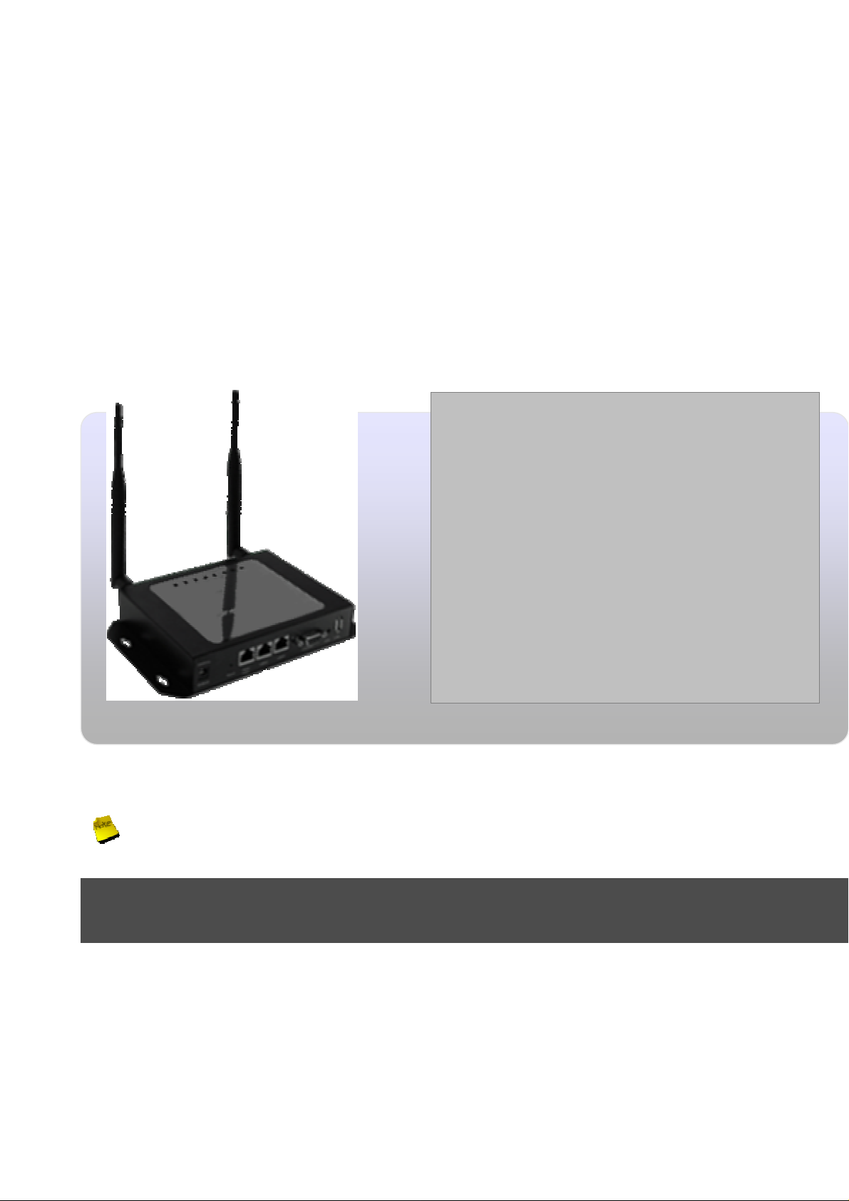
stores who want to provide small, single-point wireless Internet access service. AP-952X is a perfect
choice for beginners to run hotspot businesses. It does not cost a fortune to buy a pile of equipment,
nor does it take the skills of an expert to glue multiple applications out of multiple freeware. Featurepacked for hotspot operation, AP-952X comes with built-in 802.11n/b/g access point, web server and
web pages for clients to login, easy logo-loading for branding a hotspot store, simple
user/visitor account management tool, payment plans, PayPal credit card gateway, traffic logs,
IP sharing and etc.
1.2 Package Contents
Package Contents
• AC-952X x 1
It is highly recommended to use all the supplies in the package instead of substituting any components by
other suppliers to guarantee best performance.
Chapter 2. System Overview
• Quick Installation Guide x 1
• CD-ROM (with User Manual and QIG) x 1
• Power Adapter DC12V 1.5A x 1
• Antenna x 2
• Ground Cable x 1
• Mounting Kit
x 1
2.1 Introduction of AP-952X
Aspiring to provide the best performance/price ratio for both SMB and industrial applications, AP-952X
is uniquely designed for Wall Mount with metal case and IP50 rating for a fast, robust, secure and
business class access point perfect for installation in factories, warehouses, hotels marinas, hospitals,
large homes, hotspot and more.
Page 5

AP-952X is compliant to the latest wireless standards that are required in highly secured enterprise
networking environments. Its Wireless Distribution System (WDS) feature allows for flexible extension
of wireless coverage. DC jack providing the ability to back up each other with fail-over redundancy
function, giving AP-952x reliable connectivity in mission critical situations.
AP-952X is easy-to-use and install with web-based administrative interface making configuration and
client management simple and easy. In addition, management interfaces such as CLI and SNMP are
also supported by AP-952X
AP952X built-in software interface allows for communicating with other types of network management
servers. AP952X can further provide enhanced values in a well managed WLAN solution by our
backend controlling gateway.
Page 6

AP-952X Industrial Wall-mounted Wirele ss-N/BG AP/Bridge
User's Manual
2.2 Specification
Wireless Architecture Mode :
AP Mode
WDS Mode (Repeater/Brdige)
Access Point Feature
Number of ESSID : 8
Number of associated clients per AP : 32
WDS Mode : to extend wireless coverage by connecting wirelessly to another WDS capable AP. Support up
to 4 WDS links
Slot Time , ACK/CTS Timeout
RSSI threshold support
TX burst support
Beacon interval: adjustable to best adapt to the deployment environment
IAPP : to facilitable faster roaming for the stations among different APs nearby
RTS and fragmentation control
Adjustable transmission power : 7 Levels
Wireless site survey : for scanning the surrounding access points for connection
VLAN tag support
Authentication/Encryption (Wireless Security)
Data encryption: WEP(64/128/152-bits) , WPA/WPA2 with TKIP or AES-CCMP
User Authentication : WEP, IEEE802.1X,WPA-PSK, WPA-Enterprise , MAC ACL
Setting for TKIP/CCMP/AES key’s refreshing period
Support IEEE802.11 mixed mode, open and shared key authentication
Hidden ESSID: broadcast SSID option can be turn off to prevent SSID broadcast to the public
Station Isolation setting : when enabled , all stations associated with this AP can not communicate with each
other
Support data encryption over WDS link
Quality of Service
DiffServ/TOS
IEEE802.11p/COS
IEEE 802.11Q Tag VLAN priority control
IEEE802.11e WMM
6
Page 7

AP-952X Industrial Wall-mounted Wirele ss-N/BG AP/Bridge
Management
Web-Based management interface
Remote configuration and management
Remote firmware upgradeable
Software one-button-click to reset back to factory defaults
Utilities for system configuration backup and restoration
SNMP MIBII support (v2c/v3)
NTP time synchronization
Syslog client
Support Event log
Support statistics on total transmission encountered and transmitting error occurred
User's Manual
AP-952X Hardware Specifications
Base Platform AR7240+AR9283
CPU Clock Speed 400 MHz
Wireless Radio 802.11bgn
Serial Port 1 (DB-9)
USB Port (Optional) 1 (ODM only)
Reset Switch Built-in Push-button momentary contact switch
RF Channel Scan Hardware
Button
Standards Conformance IEEE 802.3 / IEEE 802.3u
Ethernet Configuration 10/100BASE-TX auto-negotiation Ethernet port x 2/3 (RJ-45 connector)
SDRAM On board : 32 Mbytes
Flash On board : 8 Mbytes
Built-In LED Indicators 1x Power, 1 x WAN, 2 x LAN , 1 x WLAN, 1x Status, 1x System
Hardware Push-button to scan for a better channel to use
LAN * 2
Auto MDI/MDI-X enabled , Auto Fail over
7
Page 8

IEEE 802.11b mode: 19.75 dBm
IEEE 802.11g mode: 21.28 dBm
draft 802.11n Standard-20 MHz Channel mode: 22.97
draft 802.11n Wide-40 MHz Channel mode: 24.36 dBm
Wireless Specifications
AP-952X Industrial Wall-mounted Wirele ss-N/BG AP/Bridge
User's Manual
Network Standards
Conformance
Data Transfer Rate
Frequency Range
Media Access Protocol CSMA / CA with ACK
Modulation Method
Operating Channels 802.11b/g/n : 11 for FCC,14 for Japan,13 for Europe, 2 for Spain, 4 for France
RF Output Power 100mW
Transmit Power Variation 802.11g/n : Up to 16 dBm
Frequency Response flatness ±1dB over operating range
Receiver Sensitivity 802.11b/g /n
IEEE802.11 b /g /n compliant
IEEE802.11b:1 / 2 / 5.5 / 11Mbps (auto sensing)
IEEE802.11g:6 / 9 / 12 / 18 / 24 / 36 / 48 / 54 Mbps (auto sensing)
IEEE802.11n : 300 Mbps (auto sensing)
IEEE802.11b/g:
2.412 ~ 2.462GHz (USA)
2.412 ~ 2.484GHz (Japan)
2.412 ~ 2.472 GHz (Europe ETSI)
2.457 ~ 2.462 GHz (Spain)
2.457 ~ 2.472 GHz (France)
IEEE802.11b:DSSS (DBPK,DQPSK,CCK)
IEEE802.11g/n:OFDM(64-QAM,16-QAM,QPSK,BPSK)
802.11b : up to 18 dBm
-90dBm@1Mbps, -86dBm@6Mbps,-84dBm@11Mbps,-69dBm@54Mbps
Environmental & Mechanical Characteristics
Operating Temperature -20 °C ~ 50 °C
Storage Temperature -20 °C ~ 60 °C
Operating Humidity 10% to 80% Non-Condensing
Storage Humidity 5% to 90% Non-Condensing
Antenna Connector SMA-Type Connector
Power Supply 110 – 220V AC Power ; 12 VDC, 1.5A input.
Support 802.3af Compliant , Power Over Ethernet (48V/0.3 A)
Unit Dimensions 205 x 125 x 35 (mm) (Width x Depth x Height)
Unit Weight 600g
Form Factor Wall Mountable , Metal case compliant with IP50 standard
Certifications FCC,CE, IP50,ROHS compliant
8
Page 9
AP-952X Industrial Wall-mounted Wirele ss-N/BG AP/Bridge
Chapter 3. Base Installations
3.1 Installations
3.1.1 System Requirements
Standard 10/100Base T including five network cables with RJ-45 connectors
All PCs need to install the TCP/IP network protocol
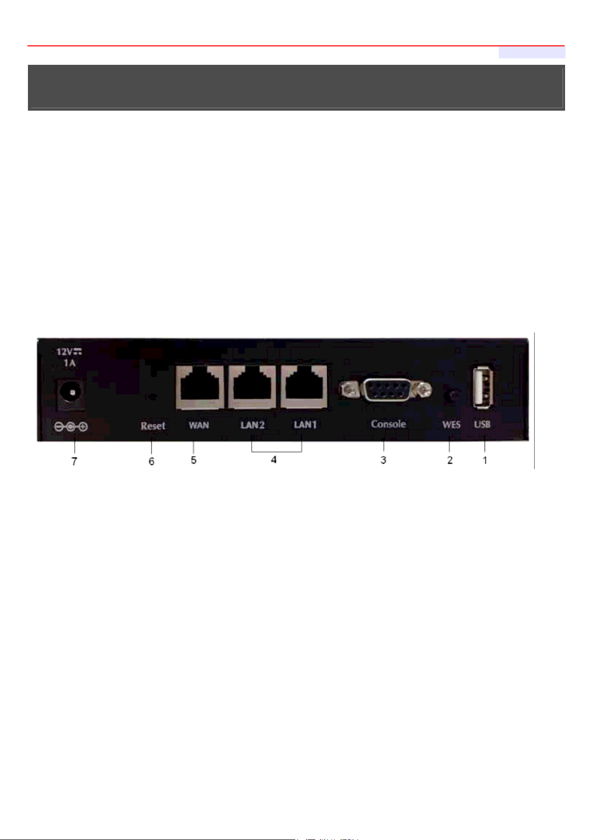
3.1.2 Panel Function Descriptions
Front Panel
3-Port
User's Manual
1. USB:Disabled for future usage only
2. WES:Press to start running WES process
3. Console : The serial RS-232 DB9 cable attaches here.
4. LAN1/LAN2 : Attach Ethernet cables here for connecting to the wired local network. LAN1 maps to
Private Zone and requires no user authentication, LAN2 maps to Public Zone and by default requires user
authentication.
5. WAN : Attach the wired external network here.
6. Reset : Press the Reset button once to restart the system, The LED except Power indicator will be off
before restarting.
7. Power Socket : For connecting to external power supply via the power adapter.
Rear Panel
9
Page 10
AP-952X Industrial Wall-mounted Wirele ss-N/BG AP/Bridge
escriptio
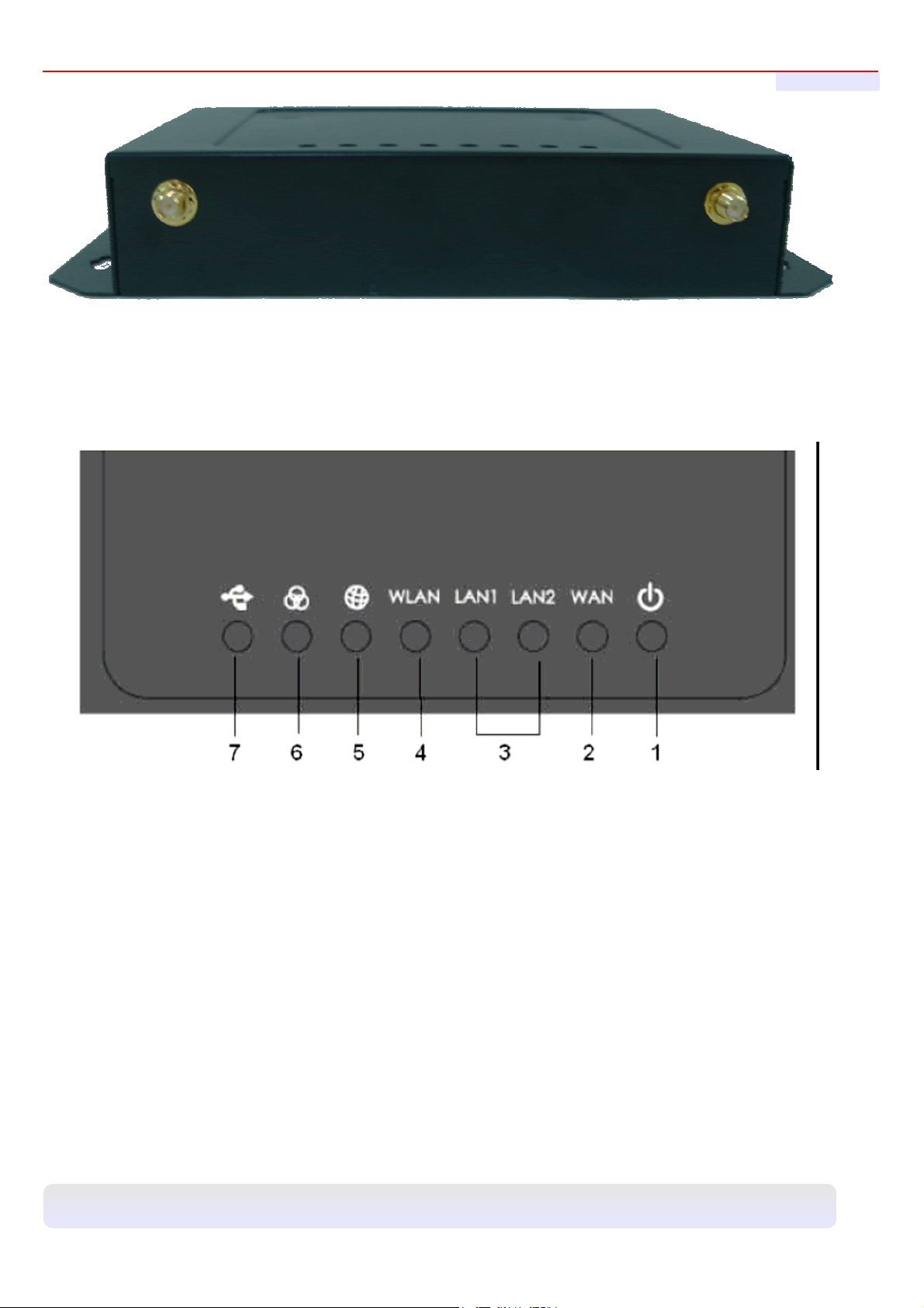
AP-952X supports 1 RF interface with 2 SMA connectors for Antenna connection.
LED Panel
User's Manual
1. Power : LED ON indicates power on, OFF indicates power off.
2. WAN : LED ON indicates WAN connection; OFF indicates no connection; BLINKING indicates transmitting data.
3. LAN1/LAN2 : LED ON indicates connection, OFF indicates disconnection, FLASH indicates packets transmitting.
4. WLAN : LED ON indicates Wireless ready.
5. SYSTEM : LED ON indicates Flash busy, OFF indicates Flash Idle
6. STATUS : LED ON indicates System up, OFF indicates down, FLASH indicates Scan button activated.
7. USB : For future usage only.
;
.
Panel Function D
n
10
Page 11
AP-952X Industrial Wall-mounted Wirele ss-N/BG AP/Bridge
User's Manual
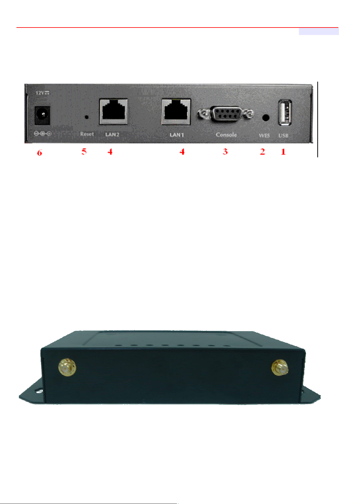
Front Panel
2-Port
1. USB:Disabled for future usage only
2. WES:Press to start running WES process
3. Console : The serial RS-232 DB9 cable attaches here.
4. LAN1/LAN2 : Attach Ethernet cables here for connecting to the wired local network. LAN1 maps to
Private Zone and requires no user authentication, LAN2 maps to Public Zone and by default requires
user authentication.
5. Reset : Press the Reset button once to restart the system, The LED except Power indicator will be off
before restarting.
6. Power Socket : For conn ecting to external power supply via the power adapter.
Rear Panel
■ AP-952X supports 1 RF interface with 2 SMA connectors for Antenna connection.
11
Page 12

AP-952X Industrial Wall-mounted Wirele ss-N/BG AP/Bridge
User's Manual
LED Panel
1. Power : LED ON indicates power on, OFF indicates power off.
2. LAN1/LAN2 : LED ON indicates connection, OFF indicates disconnection, FLASH indicates packets
transmitting.
3. WLAN : LED ON indicates Wireless ready.
4. SYSTEM : LED ON indicates Flash busy, OFF indicates Flash Idle
5. STATUS : LED ON in dicates System up, OFF indicates down, FLASH indicates Scan button activated.
6. USB : For future usage only.
12
Page 13

AP-952X Industrial Wall-mounted Wirele ss-N/BG AP/Bridge
User's Manual
3.1.3 Hardware Installation
Please follow the steps mentioned below to install the hardware of AP-952X
1. Place the AP-952X at a best location.
The best location for AP-952X is usually at the center of your wireless network.
2. Connect AP-952X to your outbound network device.
Connect one end of the Ethernet cable to the LAN port of AP-952X on the front panel and the other end of the cable
to a switch, a router or a hub. AP-952X is then connected to your existing wired LAN network. The LAN LED
indicator should be ON to indicate a proper connection.
3. There are two ways to supply power over to AP-952X
Connect the DC power adapter to the AP-952X power socket on the front panel.
Please only use the power adapter supplied with the AP-952X package. Using a different power adapter
may damage this system
Now, the hardware installation is completed.
To double verify the wired connection between AP-952X and your switch/router/hub, please check the
LED status indication of these network devices.
13
Page 14

AP-952X Industrial Wall-mounted Wirele ss-N/BG AP/Bridge
User's Manual
3.2 Software Configuration
3.2.1 Getting Start
AP-952X supports web-based configuration. Upon the completion of hardware installation, AP-952X
can be configured through a PC by using its web browser such as Mozilla Firefox 3.5 or Internet
Explorer version 8.0.
Default IP Address : 192.168.2.254
Default IP Netmask : 255.255.255.0
Default User Name and Password : root / default
Step :
1. IP Segment Set-up for Administrator's PC/NB
Set the IP segment of the administrator's computer to be in the same range as AP-952X for accessing the
system. Do not duplicate the IP Address used here with IP Address of AP-952X or any other device within the
network
Example of Segment :
The value for underlined area can be changed as desired; the valid range is 1 ~ 254. However, 254 shall be
avoided as it is already used by AP-952X; use 10 as an example here.
IP Address : 192.168.2.10
IP Netmask : 255.255.255.0
2. Launch Web Browser
Launch a web browser to access the web GUI of AP-952X by entering “http://192.168.2.254” in the address field.
3. System Login
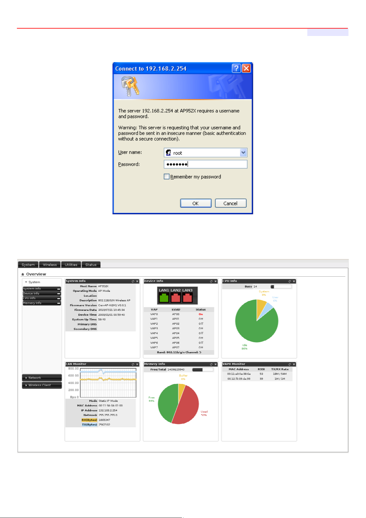
The following Administrator Login Page will appear. Enter “root” in the Username field, and “default” in the
Password field
14
Page 15
AP-952X Industrial Wall-mounted Wirele ss-N/BG AP/Bridge
User's Manual
4. Login Success
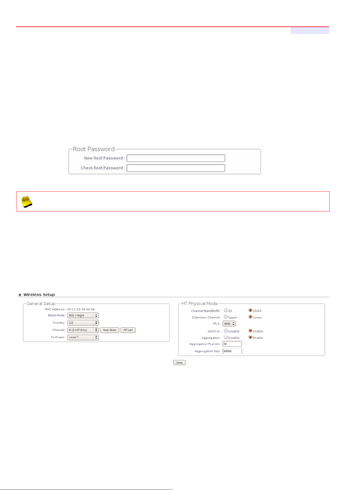
After a successful login, the “System Overview” will appear on the screen.
15
Page 16
AP-952X Industrial Wall-mounted Wirele ss-N/BG AP/Bridge
User's Manual
3.2.2 Quick Configuration
Configuration Steps :
Step 1 : Change Root's Password
Click System -> Management, the Management Setup page will appear.
Enter a New Root Password for the Root account ad retype in the Check Root Password field. (4-30
alphanumeric and specific characters; not support Space)
Click Save button.
For security concern, it is strongly recommended to change the Root password.
Step 2 : Configure Wireless General Settings
Click Wireless -> General Setup, the Wireless General Setup page will appear.
Select desired wireless Band, Channel.
Click Save button
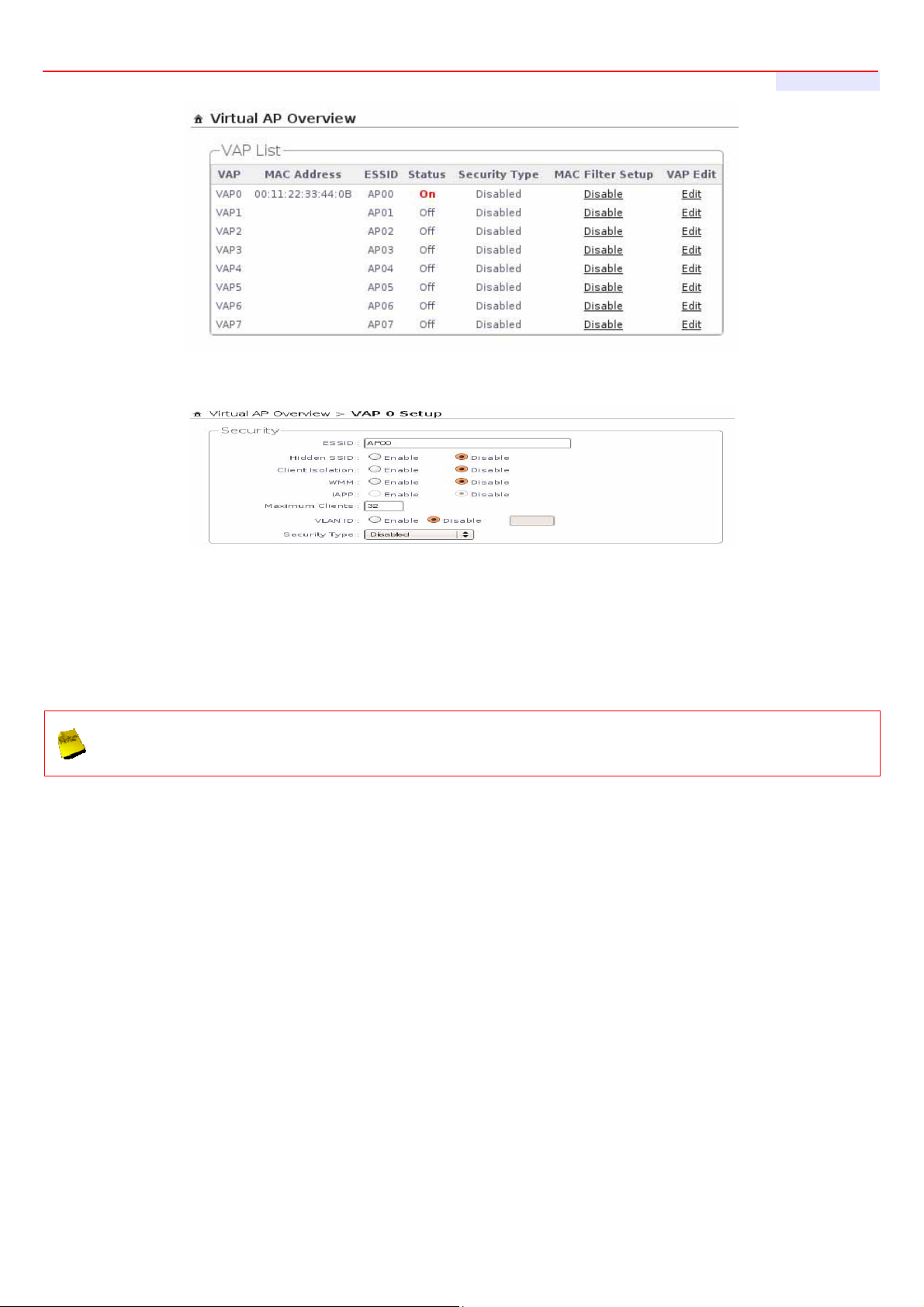
Step 3 : Configure Virtual AP
Click Wireless -> Virtual AP Setup ,the Virtual AP Overview page will appear.
16
Page 17
AP-952X Industrial Wall-mounted Wirele ss-N/BG AP/Bridge
Click “Edit” button of VAP0's row on VAP List, the VAP0 Setup page will appear
User's Manual
Setup the broadcasting ESSID for easily identifying the system when device is trying to associate the service.
Click Save button
On each configuration page, you may Click “
system upon the completion of all configuration settings for the changes to take effect. When clicking
“
”, the following message will appear : “
Save
” button to save the changes, but you must reboot the
Save
Press Reboot to Enable New Setting.
”
Congratulation !
Now, AP-952X is installed and configured successfully.
17
Page 18
AP-952X Industrial Wall-mounted Wirele ss-N/BG AP/Bridge
User's Manual
Chapter 4. AP Mode Configuration
When AP mode is activated, the system can be configured as an Access Point. This section provides information in
configuring the AP mode with graphical illustrations. AP-952X provides functions as stated below where they can be
configured via a user-friendly web based interface.
OPTION System Wireless Utilities Status
Operating Mode General Setup Profile Setting Overview
LAN Advanced Setup Firmware Upgrade Extra Info
Function
After finishing the configuration of the settings, please click Save button and pay attention to see if a
Reboot message appears on the screen. If such message appears, system must be restarted to allow the
settings to take effect. All online users will be disconnected during restart.
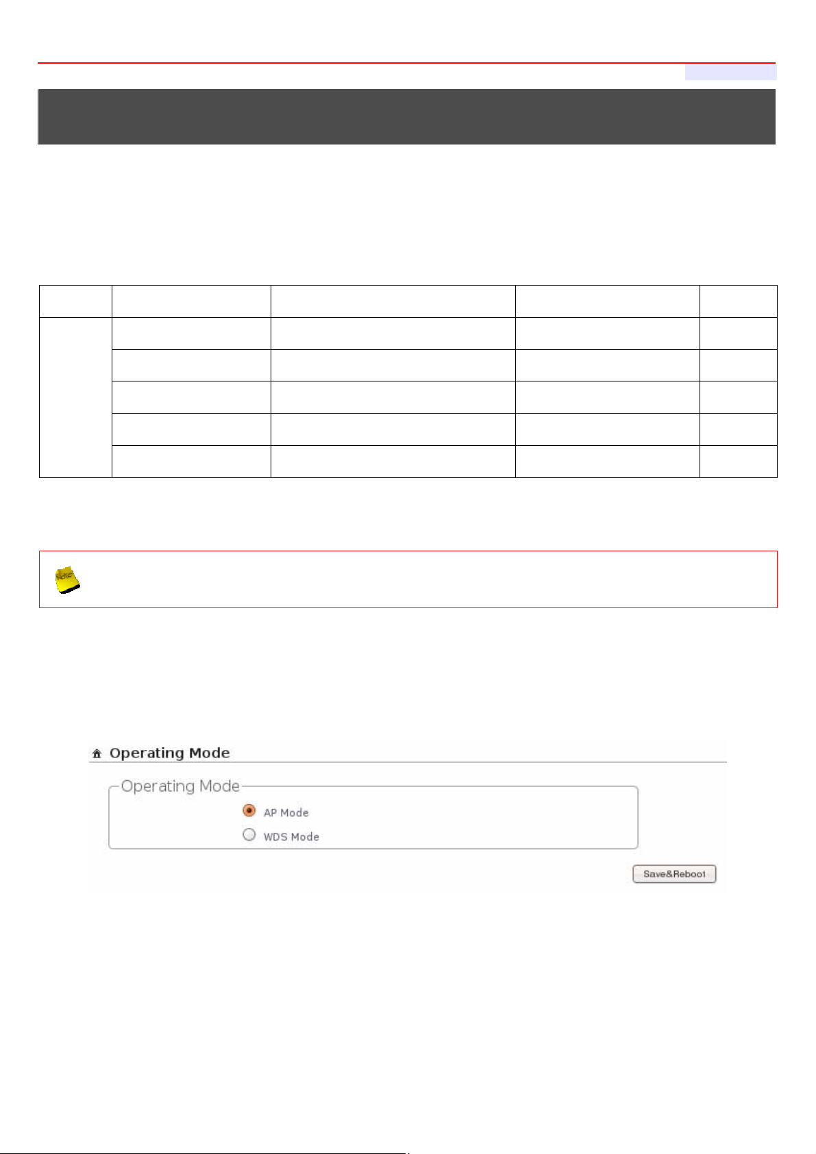
AP-952X supports two operation modes; AP mode and WDS mode. Click System -> Operating Mode, the
administrator can set the desired mode via this page, and then configure the system according to their deployment
needs.
Management Virtual AP Setup Network Utility Event Log
Time Server Associated Clients Reboot
SNMP WDS Status
Table 4-1: AP Mode Functions
AP Mode : Check AP Mode button to enable AP mode, and then click “Save&Reboot” to activate the
setting.
WDS Mode : Check WDS Mode button to enable AP mode, and then click “Save&Reboot” to activate the
setting.
18
Page 19
AP-952X Industrial Wall-mounted Wirele ss-N/BG AP/Bridge
User's Manual
4.1 Connect AP-952X to the Wired Local Network
4.1.1 Network Requirement
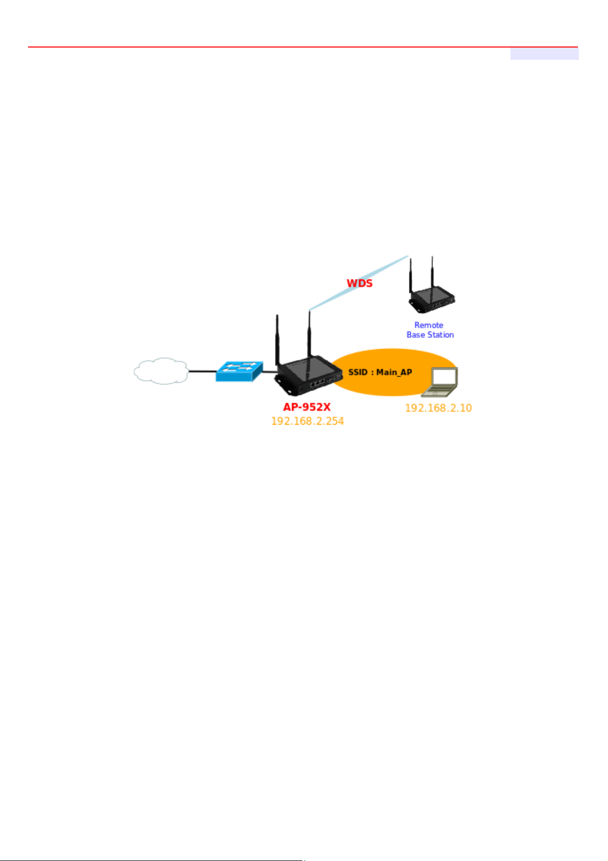
Normally, AP-952X connects to a wired LAN and provides a wireless connection point to associate with wireless
client as shown in Figure 4-1. Then, Wireless clients could access to LAN or Internet by associating themselves with
AP-952X set in AP mode.
Figure 4-1 Access Point on a Wired LAN Configuration
19
Page 20
AP-952X Industrial Wall-mounted Wirele ss-N/BG AP/Bridge
User's Manual
4.1.2 Configure LAN Port
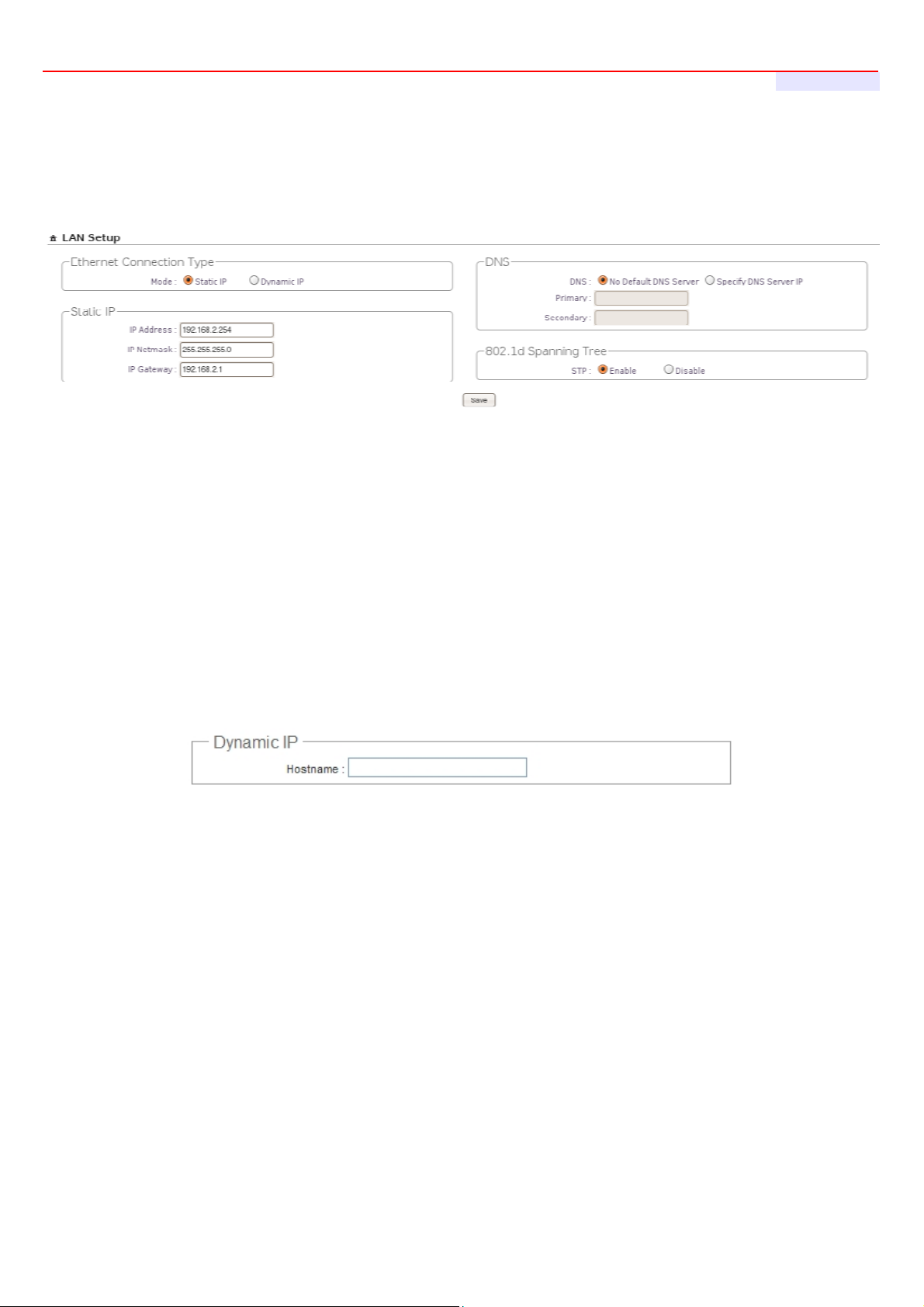
Here is instruction for how to setup the LAN. The connection types for LAN port : Static IP and Dynamic IP, Please click
on System -> LAN and follow the below setting.
Mode : Check either “Static IP” or “Dynamic IP” button as desired to set up the system IP of LAN port .
Static IP : The administrator can manually setup the LAN IP address when static IP is available/ preferred.
IP Address : The IP address of the LAN port; default IP address is 192.168.2.254
IP Netmask : The Subnet mask of the LAN port; default Netmask is 255.255.255.0
IP Gateway : The default gateway of the LAN port; default Gateway is 192.168.2.1
Dynamic IP : This configuration type is applicable when the WCB1200H5PX is connected to a network
with the presence of a DHCP server; all related IP information will be provided by the DHCP server
automatically.
Hostname : The Hostname of the LAN port
DNS : Check either “No Default DNS Server” or “Specify DNS Server IP” button as desired to set up the system
DNS.
Primary : The IP address of the primary DNS server.
Secondary : The IP address of the secondary DNS server.
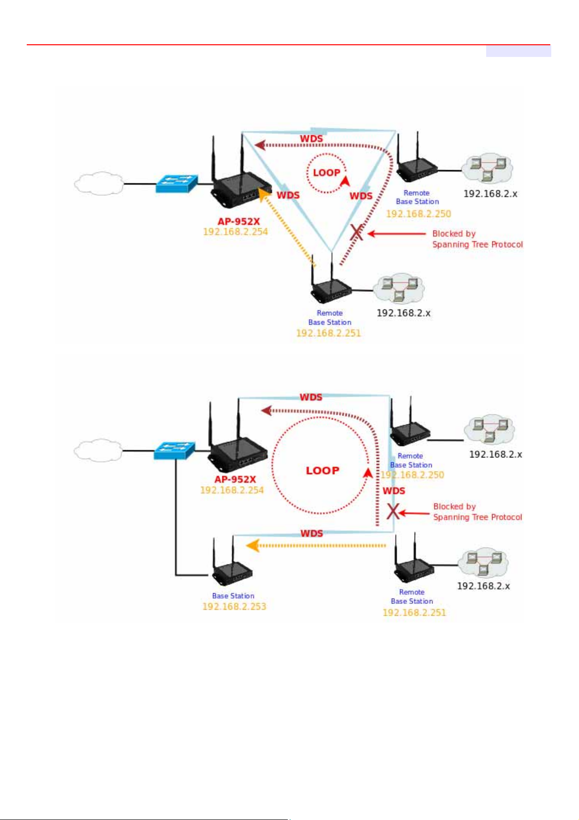
802.1d Spanning Tree
The spanning tree network protocol provides a loop free topology for a bridged LAN between LAN interface and
4 WDS interfaces from WDS0 to WDS3. The Spanning Tree Protocol, which is also referred to as STP, is defined
in the IEEE Standard 802.1d. The Spanning tree always enabled on AP-952X. Below Figures depict a loop for a
bridged LAN between LAN and WDS link
20
Page 21
AP-952X Industrial Wall-mounted Wirele ss-N/BG AP/Bridge
User's Manual
Click Save button to save your changes. Click Reboot button to activate your changes
21
Page 22
AP-952X Industrial Wall-mounted Wirele ss-N/BG AP/Bridge
User's Manual
4.2 Create Your Wireless Network
The system manager can configure related wireless settings, General Settings, Advanced Settings, Virtual
AP(VAP) Setting, Security Settings and Access Control Settings.
4.2.1 Configure Wireless General Setup
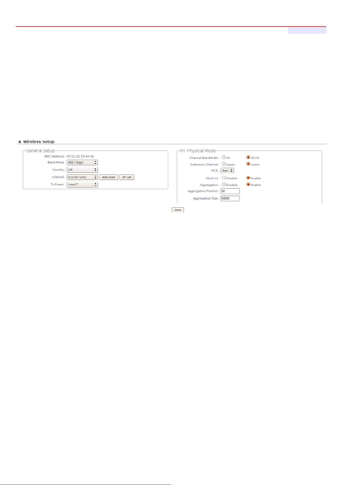
The administrator can change the data transmission, channel and output power settings for the system. Please click
on Wireless -> General Setup and follow the below setting.
8. MAC address : The MAC address of the Wireless interface is displayed here.
9. Band Mode : Select an appropriate wireless band; bands available are 801.11b, 802.11b/g, 802.11b/g/n and
802.11n.
10. Transmit Rate Control : Select the desired rate from the drop-down list; the options are auto or ranging
from 1Mbps to 54Mbps for 802.11b/g modes, or 1Mbps to 11Mbps for 802.11b mode.
11. Country : Select the desired country code from the drop-down list; the options are US, ETSI and Japan.
12. Channel : The channel range will be changed by selecting different country code. The channel range from 1
to 11 for US country code, or 1 to 13 for ETSI country code, or 1 to 14 for Japan(Channel 14 only for
802.11b Rate).
Click “Auto Scan”, the channel will change to next channel. Click “AP List” button, the system will show current all
AP list.
22
Page 23

AP-952X Industrial Wall-mounted Wirele ss-N/BG AP/Bridge
User's Manual
13. Tx Power : You can adjust the output power of the system to get the appropriate coverage for your wireless
network. Select LEVEL 1 to LEVEL 7 needed for your environment. If you are not sure of which setting to
choose, then keep the default setting, LEVEL 7.
When Band Mode select in 802.11b/gn or 802.11n, the HT Physical Mode settings should be show immediately.
Channel Bandwidth : The "20/40” MHz option is usually best. The other option is available for special
circumstances.
Extension Channel : Only for Channel Bandwidth “40” MHz. Select the desired channel bonding for control.
MCS : This parameter represents transmission rate. By default (Auto) the fastest possible transmission rate will
be selected. You have the option of selecting the speed if necessary.
Shout GI : Short Guard Interval, by default, it's “Enable”. it's can increase throughput. However, it can also
increase error rate in some installations, due to increased sensitivity to radio-frequency reflections. Select the
option that works best for your installation.
Aggregation : By default, it's “Enable”. To “Disable” to deactivated Aggregation.
A part of the 802.11n standard (or draft-standard). It allows sending multiple frames per single access to the medium
by combining frames together into one larger frame. It creates the larger frame by combining smaller frames with
the same physical source and destination end points and traffic class (i.e. QoS) into one large frame with a common
MAC header.
Aggregation Frames : The Aggregation Frames is in the range of 2~64, default is 32. It determines the number
of frames combined on the new larger frame.
Aggregation Size : The Aggregation Size is in the range of 1024~65535, default is 50000. It determines the size
(in Bytes) of the larger frame.
Change these settings as described here and click Save button to save your changes. Click Reboot button to
activate your changes. The items in this page is for AP's RF general settings and will be applied to all VAPs and
WDS Link.
23
Page 24
AP-952X Industrial Wall-mounted Wirele ss-N/BG AP/Bridge
User's Manual
4.2.2 Configure Wireless Advanced Setup
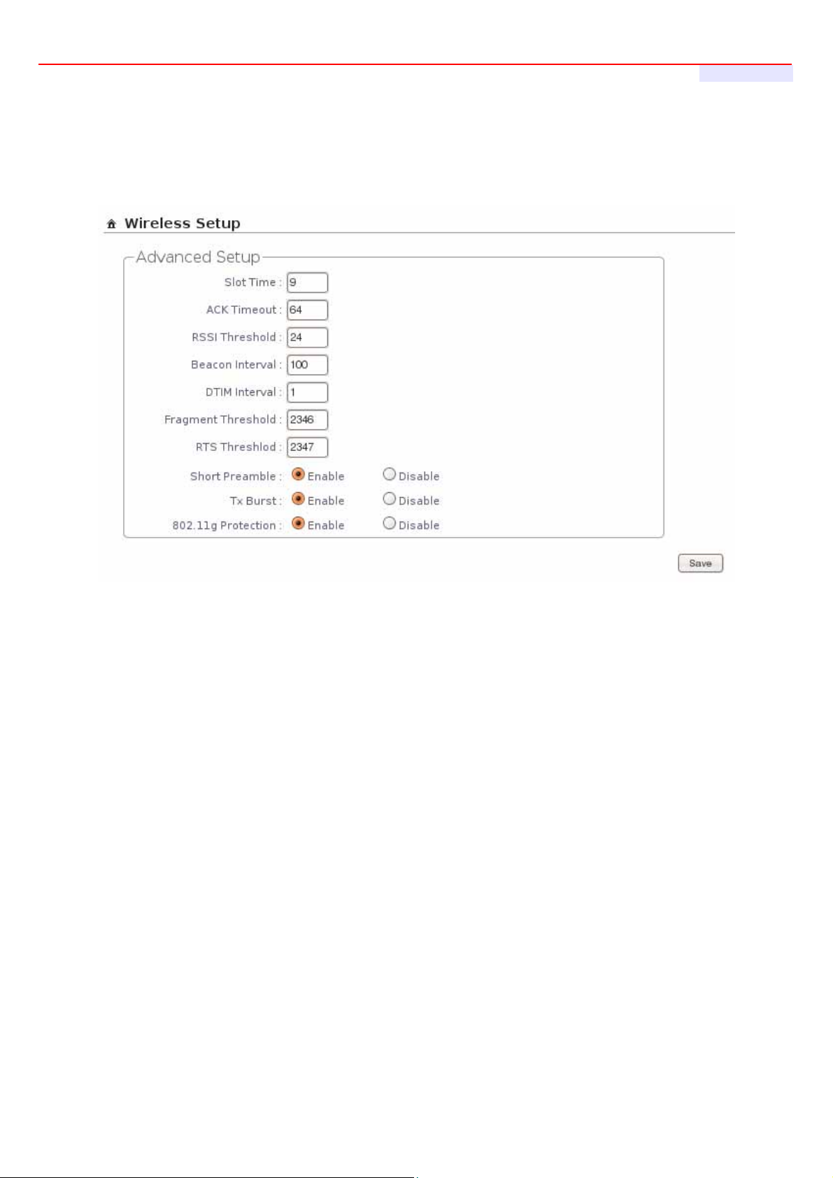
The administrator can change the Slot Time, ACK Timeout, RTS threshold and fragmentation threshold settings for
the system. Please click on Wireless -> Advanced Setup and follow the below setting.
Slot Time : Slot time is in the range of 9~1489 and set in unit of microsecond. The default value is 9
microsecond.
Slot time is the amount of time a device waits after a collision before retransmitting a packet. Reducing the slot
time decreases the overall back-off, which increases throughput. Back-off, which is a multiple of the slot time, is
the random length of time a station waits before sending a packet on the LAN. For a sender and receiver own
right of the channel the shorter slot time help manage shorter wait time to re-transmit from collision because of
hidden wireless clients or other causes. When collision sources can be removed sooner and other senders
attempting to send are listening the channel(CSMA/CA) the owner of the channel should continue ownership
and finish their transmission and release the channel. Then, following ownership of the channel will be sooner
for the new pair due to shorter slot time. However, when long duration of existing collision sources and shorter
slot time exist the owners might experience subsequent collisions. When adjustment to longer slot time can’t
improve performance then RTS/CTS could supplement and help improve performance.
ACK Timeout : ACK timeout is in the range of 1~372 and set in unit of microsecond. The default value is 64
microsecond.
All data transmission in 802.11b/g request an “Acknowledgement” (ACK) send by receiving radio. The
transmitter will resend the original packet if correspondent ACK failed to arrive within specific time interval, also
refer to as “ACK Timeout”.
24
Page 25

AP-952X Industrial Wall-mounted Wirele ss-N/BG AP/Bridge
User's Manual
ACK Timeout is adjustable due to the fact that distance between two radio links may vary in different
deployment. ACK Timeout makes significant influence in performance of long distance radio link. If ACK
Timeout is set too short, transmitter will start to “Resend” packet before ACK is received, and throughput
become low due to excessively high re-transmission.
ACK Timeout is best determined by distance between the radios, data rate of average environment. The
Timeout value is calculated based on round-trip time of packet with a little tolerance, So, if experiencing retransmissions or poor performance the ACK Timeout could be made longer to accommodate.
Slot Time and ACK Timeout settings are for long distance links. It is important to tweak settings to achieve
the optimal result based on requirement.
RSSI Threshold : RSSI(Received Signal Strength Indication) Threshold is in the range of -127 ~ 128. The
default value is 24. RSSI Threshold can be used to control the level of noise received by the device.
Beacon Interval : Beacon Interval is in the range of 40~3500 and set in unit of millisecond. The default value is
100 msec.
Access Point (AP) in IEEE 802.11 will send out a special approximated 50-byte frame, called “Beacon”. Beacon
is broadcast to all the stations, provides the basic information of AP such as SSID, channel, encryption keys,
signal strength, time stamp, support data rate.
All the radio stations received beacon recognizes the existence of such AP, and may proceed next actions if the
information from AP matches the requirement. Beacon is sent on a periodic basis, the time interval can be
adjusted.
By increasing the beacon interval, you can reduce the number of beacons and associated overhead, but that
will likely delay the association and roaming process because stations scanning for available access points may
miss the beacons. You can decrease the beacon interval, which increases the rate of beacons. This will make
the association and roaming process very responsive; however, the network will incur additional overhead and
throughput will go down.
DTIM Interval : The DTIM interval is in the range of 1~255. The default is 1.
DTIM is defined as Delivery Traffic Indication Message. It is used to notify the wireless stations, which support
power saving mode, when to wake up to receive multicast frame. DTIM is necessary and critical in wireless
environment as a mechanism to fulfill power-saving synchronization.
A DTIM interval is a count of the number of beacon frames that must occur before the access point sends the
buffered multicast frames. For instance, if DTIM Interval is set to 3, then the Wi-Fi clients will expect to receive
a multicast frame after receiving three Beacon frame. The higher DTIM interval will help power saving and
possibly decrease wireless throughput in multicast applications.
25
Page 26

AP-952X Industrial Wall-mounted Wirele ss-N/BG AP/Bridge
User's Manual
Fragment Threshold : The Fragment Threshold is in the range of 256~2346 byte. The default is 2346 byte.
Each Wi-Fi packet can be divided into smaller packets, marked with a sequential fragment number and reassemble in the receiving ends. The purpose is to make a short frame, instead of long frame, transmitting by
radio in a heavy noisy environment. Because of sending smaller frames, corruptions are much less likely to
occur. The pros is obvious, the cons is the overhead for transmission. So, in a clean environment, higher
fragment threshold can be an option to increase throughput.
Fragmentation will be triggered by setting the Fragment Threshold, usually in Byte-length. Only when the frame
size is over the Threshold, fragmentation will take place automatically.
RTS Threshold : TRTS Threshold is in the range of 1~2347 byte. The default is 2347 byte.
The main purpose of enabling RTS by changing RTS threshold is to reduce possible collisions due to hidden
wireless clients. RTS in AP will be enabled automatically if the packet size is larger than the Threshold value. By
default, RTS is disabled in a normal environment supports non-jumbo frames.
Short Preamble : By default, it’s “Enable”. To Disable is to use Long 128-bit Preamble Synchronization field.
The preamble is used to signal "here is a train of data coming" to the receiver. The short preamble provides 72bit Synchronization field to improve WLAN transmission efficiency with less overhead.
Tx Burst : By default, it’s “Enable”. To Disable is to deactivate Tx Burst.
With TX burst enabled, AP will send many packets in a burst, without collision detection and RTS/CTS for each
packet. TX Burst have better throughput but cause interference with other APs in channel.
802.11g Protection : Click Enable button to activate 802.11g Protection Mode, and Disable to inactivate
802.11g Protection Mode.
Change these settings as described here and click Save button to save your changes. Click Reboot button to
activate your changes. The items in this page is for AP's RF general settings and will be applied to all VAPs and
WDS Link.
26
Page 27
AP-952X Industrial Wall-mounted Wirele ss-N/BG AP/Bridge
User's Manual
4.2.3 Create Virtual AP
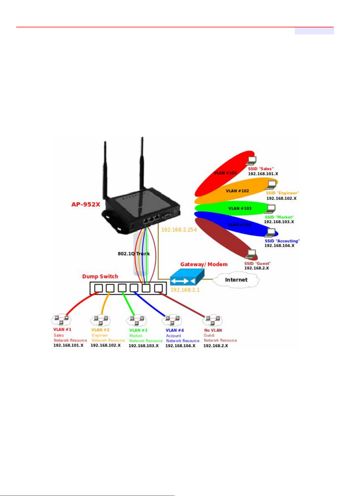
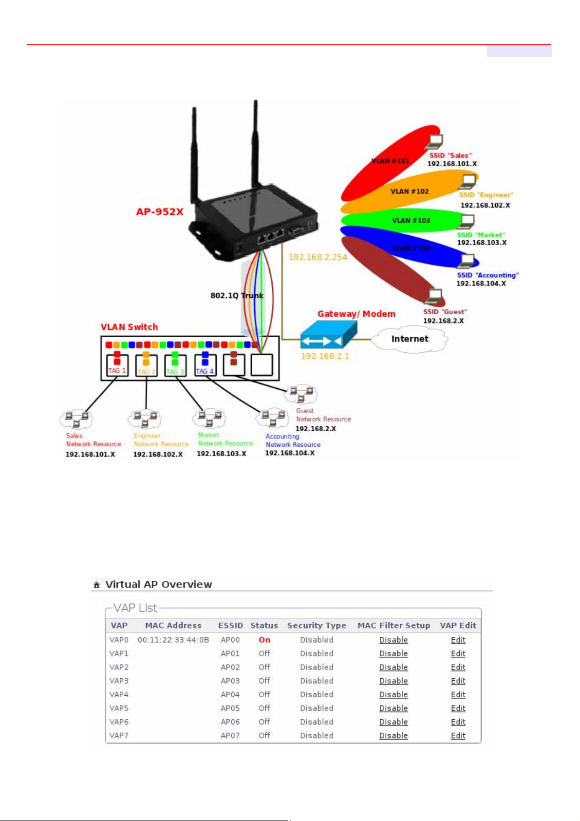
The AP-952X support broadcasting multiple SSIDs, allowing the creation of Virtual Access Points, partitioning a
single physical access point into 8 logical access points, each of which can have a different set of security, VLAN
Tag(ID) and network settings. If wireless client connect to wired area network with VLAN Tag(ID), the administrator
can use dump switch or VLAN switch on wired area network, a Figure 4-2 shows multiple SSIDs with different
VLAN settings use dump switch connect to wired area. a Figure 4-3 shows multiple SSIDs with different VLAN
settings use VLAN switch connect to wired area.
Figure 4-2 Multiple SSIDs with different VLAN settings use dump switch connect to wired area.
27
Page 28
AP-952X Industrial Wall-mounted Wirele ss-N/BG AP/Bridge
User's Manual
Figure 4-3 Multiple SSIDs with different VLAN settings use VLAN switch connect to wired area.
The administrator can create Virtual AP via this page. Please click on Wireless -> Virtual AP Setup and follow the
below setting.
28
Page 29
AP-952X Industrial Wall-mounted Wirele ss-N/BG AP/Bridge
User's Manual
14. VAP : Indicate the system's Virtual AP.
15. MAC Address : The MAC address of the VAP Interface is displayed here. When you enable AP and reboot
system, the MAC address will display here.
16. ESSID : Indicate the ESSID of the respective Virtual AP
17. Status : Indicate the current Status of the respective Virtual AP. The VAP0 always on.
18. Security Type : Indicate an used security type of the respective Virtual AP.
19. MAC Filter : Indicate an used MAC filter of the respective Virtual AP. Click button to configure MAC Filter of
the respective Virtual AP.
20. Edit : Click Edit button to configure Virtual AP's settings.
4.2.3.1 Configure Virtual AP
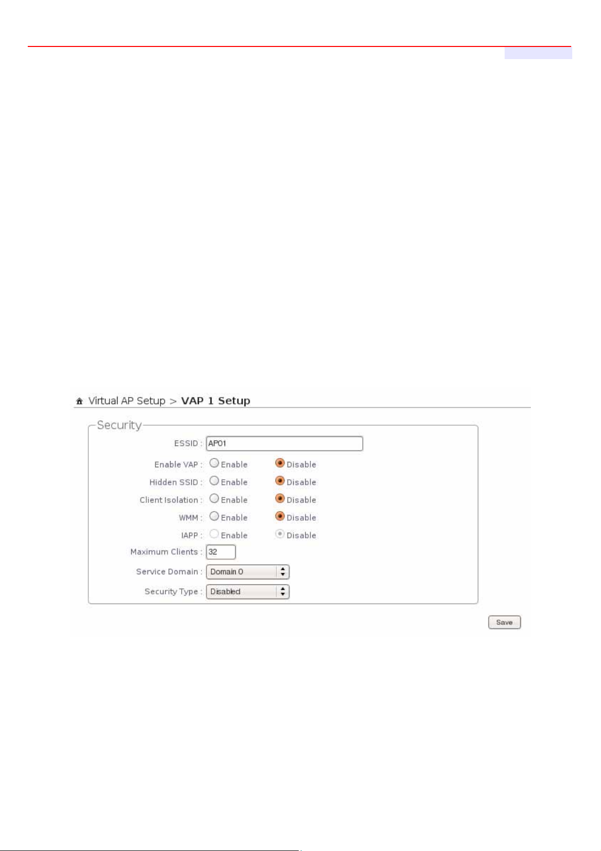
For each Virtual AP, administrators can configure general settings and security type.
Click Wireless -> Virtual AP, click “Edit” of Virtual AP List and then Virtual AP Configuration page appears.
21. ESSID : Extended Service Set ID indicates the SSID which the clients used to connect to the VAP. ESSID
will determine the service type of a client which is assigned to the specified VAP.
22. Enable AP : By default, it’s “Disable” for VAP1 ~ VAP6. The VAP0 always enabled.
Select “Enable” to activate VAP or click “Disable” to deactivate this function
29
Page 30
AP-952X Industrial Wall-mounted Wirele ss-N/BG AP/Bridge
User's Manual
23. Hidden SSID : Select this option to enable the SSID to broadcast in your network. When configuring the
network, it is suggested to enable this function but disable it when the configuration is complete. With this
enabled, someone could easily obtain the SSID information with the site survey software and get
unauthorized access to a private network. With this disabled, network security is enhanced and can prevent
the SSID from begin seen on networked.
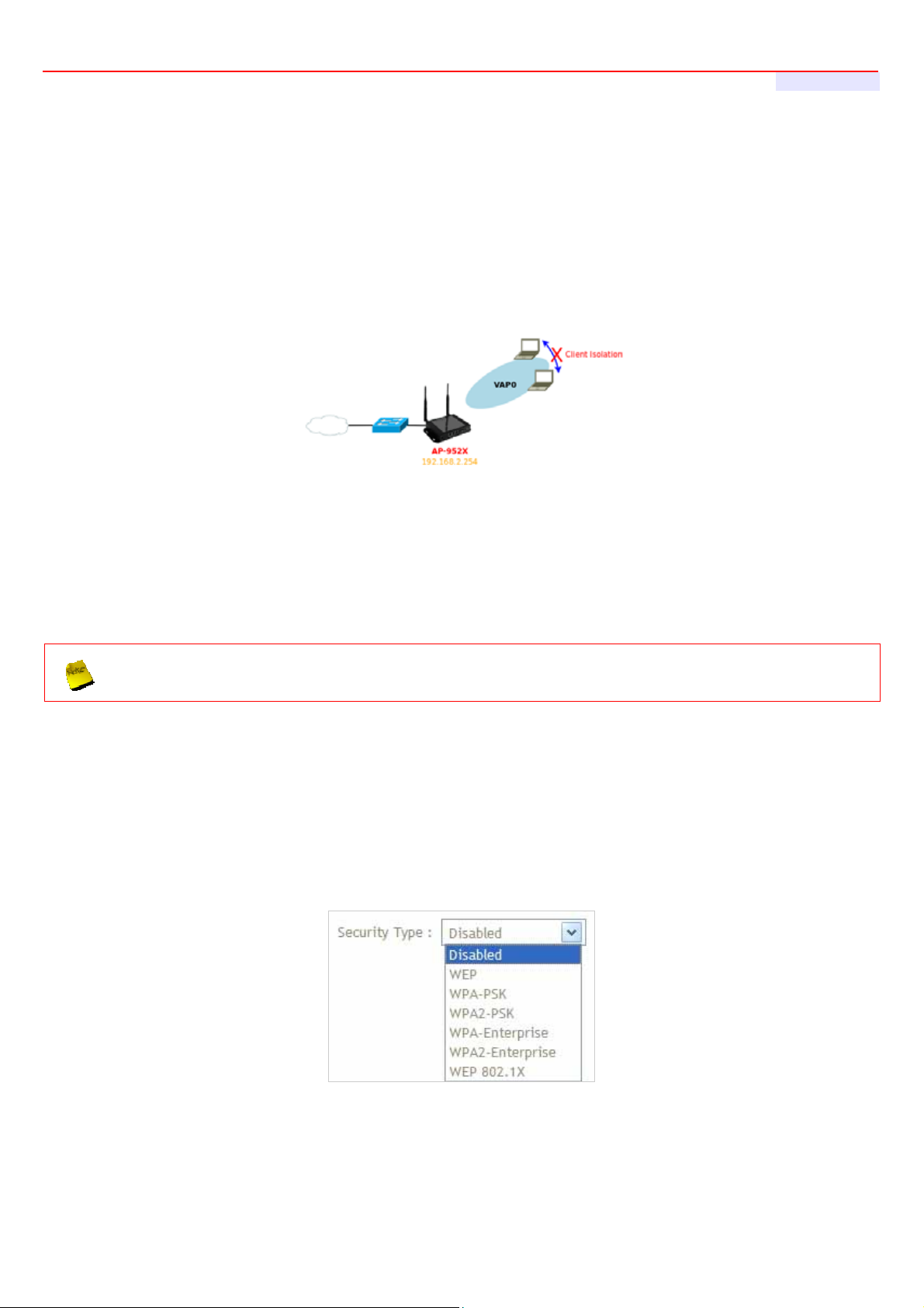
24. Client Isolation : Select Enable, all clients will be isolated from each other, that means all clients can not
reach to other clients.
25. WMM : Select Enable, the packets with QoS WMM will has higher priority.
26. IAPP Support : Inter Access-Point Protocol is designed for the enforcement of unique association
throughout a ESS(Extended Service Set) and for secure exchange of station's security context between
current access point (AP) and new AP during hand off period.
IAPP only used on WPA-PSK and WPA2-PSK security type. Only one of VAPs can be enabled
27. Maximum Clients : Enter maximum number of clients to a desired number. For example, while the number
of client is set to 32, only 32 clients are allowed to connect with this VAP.
28. Service Domain : Select the desired Service Domain from the drop-down list.
29. Security Type : Select the desired security type from the drop-down list; the options are WEP, WPA-PSK,
WPA2-PSK, WP A-Enterprise, WPA2-Enterprise and WEP 802.1X.
1. Disable : Data are unencrypted during transmission when this option is selected.
2. WEP : WEP, Wired Equivalent Privacy, is a data encryption mechanism based on a 64-bit,
128-bit or 152-bit shared key. Select WEP as the security type from the drop down list as
30
Page 31

desired.
AP-952X Industrial Wall-mounted Wirele ss-N/BG AP/Bridge
User's Manual
31
Page 32
AP-952X Industrial Wall-mounted Wirele ss-N/BG AP/Bridge
User's Manual
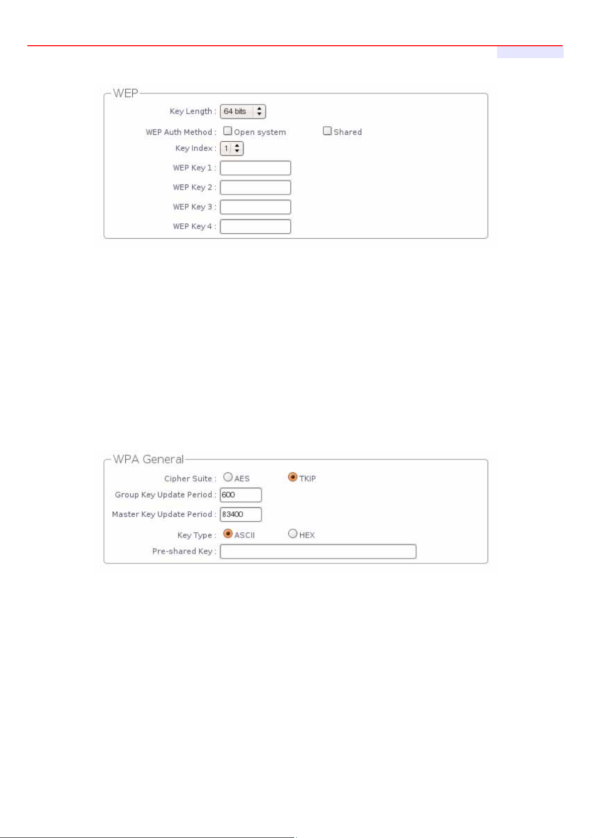
Key Length : Select the desire option are 64 bits, 128 bits or 152 bits from drop-down list.
WEP auth Method : Enable the desire option among Open system or Shared.
Key Index : Select key index used to designate the WEP key during data transmission. 4 different
WEP keys can be configured at the same time, but only one is used. Effective key is set with a choice
of WEP Key 1, 2, 3, or 4.
WEP Key : Enter HEX format WEP key value; the system support up to 4 sets of WEP keys.
3. WPA-PSK (or WPA2-PSK) : WPA (or WPA2) Algorithms, allows the system accessing the
network by using the WPA-PSK (WPA2-PSK) protected access.
Cipher Suite : Check on the respected button to enable either AES or TKIP cipher suites; default is
TKIP.
Group Key Update Period : This time interval for re-keying GTK (broadcast/multicast encryption
keys) in seconds. Enter the time-length required; the default time is 600 seconds.
Master Key Update Period : This time interval for re-keying GMK (master key used internally to
generate GTKs) in seconds. Enter the time-length required; the default time is 83400 seconds.
Key Type : Check on the respected button to enable either ASCII or HEX format for the Pre-shared
Key.
Pre-shared Key : Enter the information for pre-shared key; the format of the information shall
according to the key type selected.
32
Page 33

AP-952X Industrial Wall-mounted Wirele ss-N/BG AP/Bridge
User's Manual
Pre-shared key can be either entered as a 256-bit secret in 64 HEX digits format, or 8 to 63 ASCII
characters.
4. WPA-Enterprise (or WPA2-Enterprise): The RADIUS authentication and encryption will
be both enabled if this selected. The AP-952X support two 802.1x Authentication/
Accounting Radius Server
WPA General Settings :
• Cipher Suite : Check on the respected button to enable either AES or TKIP cipher suites.
• Group Key Update Period : This time interval for re-keying GTK (broadcast/ multicast encryption
keys) in seconds. Enter the time-length required; the default time is 600 seconds.
• Master Key Update Period : This time interval for re-keying GMK (master key used internally to
generate GTKs) in seconds. Enter the time-length required; the default time is 83400 seconds.
• EAP Reauth Period : EAP re-authentication period in seconds; default is 3600; 0 indicates
disable re-authentication.
Authentication RADIUS Server Settings :
• Authentication Server : Enter the IP address of the Authentication RADIUS server.
• Port : The port number used by Authentication RADIUS server. Use the default 1812 or enter port
33
Page 34

number specified.
AP-952X Industrial Wall-mounted Wirele ss-N/BG AP/Bridge
User's Manual
34
Page 35
AP-952X Industrial Wall-mounted Wirele ss-N/BG AP/Bridge
User's Manual
• Shared secret : The secret key for system to communicate with Authentication RADIUS server.
Support 1 to 64 characters.
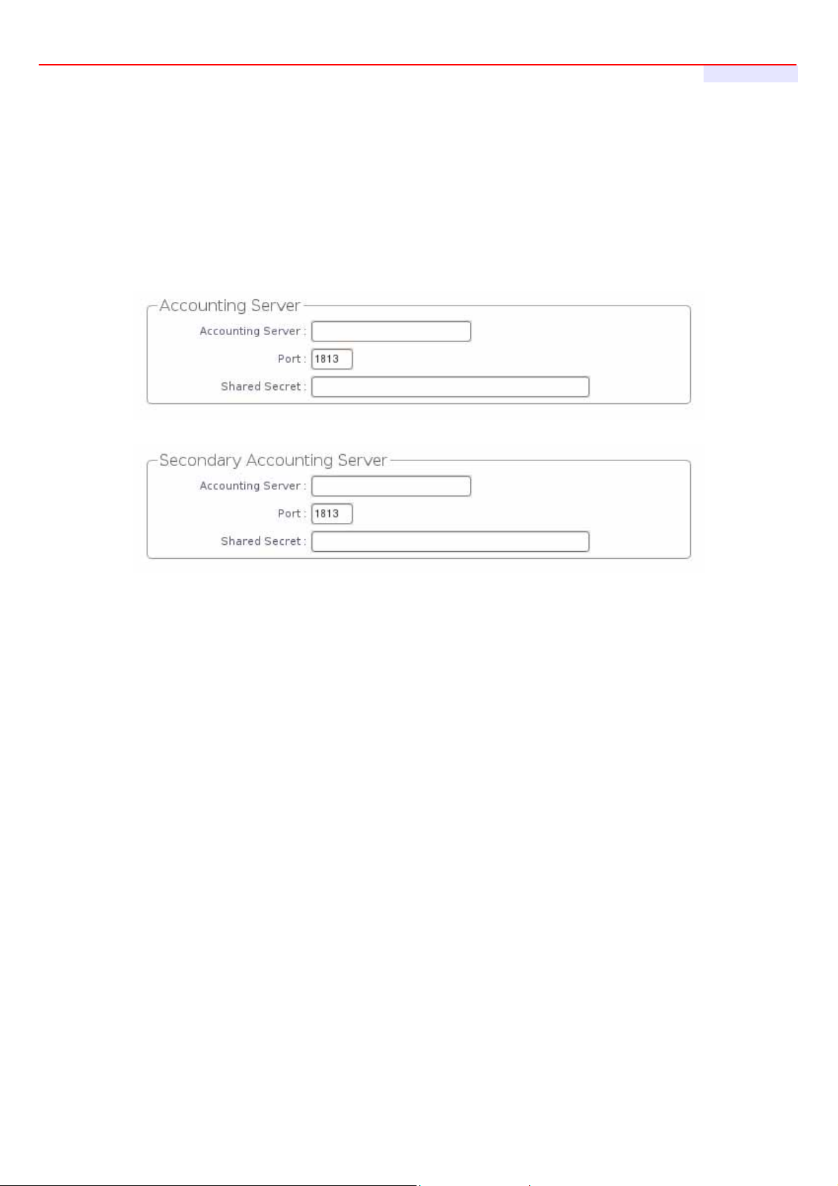
• Accounting RADIUS Server : Check on the respected button to enable eith er Enable or Disable
accounting RADIUS server.
Accounting Server Settings :
• Accounting Server : Enter the IP address of the Accounting RADIUS server.
• Port : The port number used by Accounting RADIUS server. Use the default 1813 or enter port
number specified.
• Shared Secret : The secret key for system to communicate with Accounting RADIUS server.
Support 1 to 64 characters.
WEP 802.1X : When WEP 802.1x Authentication is enabled, please refer to the following Dynamic WEP
and RADIUS settings to complete the configuration.
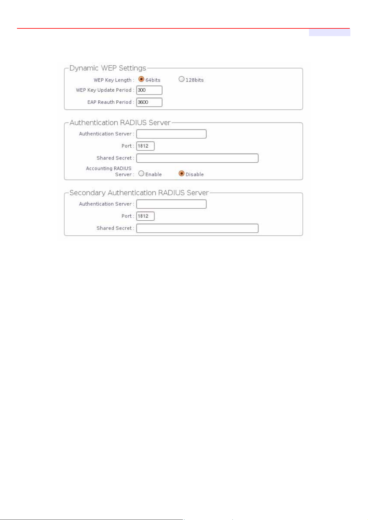
Dynamic WEP Settings :
• WEP Key length : Check on the respected button to enable either 64bits or 128bits key length.
The system will automatically generate WEP keys for encryption.
• WEP Key Update Period : The time interval WEP will then be updated; the unit is in seconds;
default is 300 seconds; 0 indicates no re-key.
• EAP Reauth Period : EAP re-authentication period in seconds; default is 3600; 0 indicates
disable re-authentication.
35
Page 36
AP-952X Industrial Wall-mounted Wirele ss-N/BG AP/Bridge
User's Manual
Authentication RADIUS Server Settings :
• Authentication Server : Enter the IP address of the Authentication RADIUS server.
• Port : The port number used by Authentication RADIUS server. Use the default 1812 or enter port
number specified.
• Shared Secret : The secret key for system to communicate with Accounting RADIUS server.
Support 1 to 64 characters.
• Accounting RADIUS Server : Check on the respected button to enable either Enable or Disable
accounting RADIUS server.
Accounting Server Settings :
• Accounting Server : Enter the IP address of the Accounting RADIUS server.
• Port : The port number used by Accounting RADIUS server. Use the default 1813 or enter port
number specified.
• Shared Secret : The secret key for system to communicate with Accounting RADIUS server.
Support 1 to 64 characters.
Change these settings as described here and click Save button to save your changes. Click Reboot button to
activate your changes
36
Page 37

AP-952X Industrial Wall-mounted Wirele ss-N/BG AP/Bridge
User's Manual
4.2.3.2 Block Wireless Clients
In this function, the administrator can be allow or reject clients to access Virtual AP. Please click on Wireless ->
Virtual AP Setup, then click button on column of MAC Filter Setup. The MAC Filter Configuration page appears.
Follow the below setting.
30. Action : Select the desired access control type from the drop-down list; the options are “Disabled”, “Only
Deny List MAC” or “Only Allow List MAC”.
define certain wireless clients in the list which will have denied access to the Access Point while the access will be
granted for all the remaining clients – Action is set to Only Deny List MAC.
define certain wireless clients in the list which will have granted access to the Access Point while the access will
be denied for all the remaining clients – Action is set to Only Allow List MAC.
31. MAC Address : Enter MAC address in this field. There are maximum 20 clients users allowed in this MAC
address list.
The MAC Address of the wireless clients can be added and removed to the MAC Filter List using the “Add” and
“Delete” buttons. Click Reboot button to activate your changes
MAC Access Control is the weakest security approach. WPA or WPA2 security methods should be used
when possible.
37
Page 38

AP-952X Industrial Wall-mounted Wirele ss-N/BG AP/Bridge
User's Manual
4.2.3.3 Monitor Associated Wireless Clients
The administrator can obtain detailed wireless information and all associated clients status via this page. Please
click on Wireless -> Associated Clients. The the Associated Clients Status appears.
Wireless Information : Display the Virtual AP configuration information of the system.
VAP : Display number of system's Virtual AP.
ESSID : Extended Service Set ID of the Virtual AP.
Status : Display Virtual AP status currently.
Security Type : Security type activated by the Virtual AP.
Clients : Number of clients currently associated to the Virtual AP.
Associated Client Status : Display the Virtual AP configuration information of the system.
AP : Virtual AP which the device is associated with.
RSSI : Indicate the RSSI of the respective client's association.
TX/RX Rate : Indicate the TX/RX Rate of the respective client's association.
TX/RX SEQ : Indicate the TX/RX sequence of the respective client's association.
Disconnect : Administrator can kick out a specific client, click “Delete” button to kick out specific client
38
Page 39
AP-952X Industrial Wall-mounted Wirele ss-N/BG AP/Bridge
4.3 Expand Your Wireless Network
4.3.1 Create WDS Link
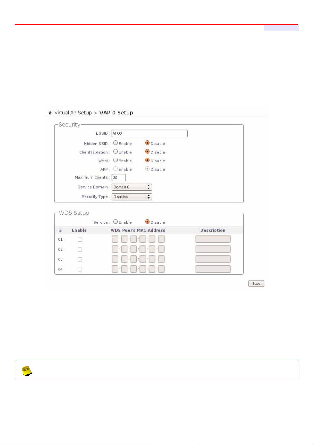
The administrator can create WDS Links for expanding wireless network via this page.
Please click on Wireless -> Virtual AP Setup -> VAP0 Setup and follow the below setting.
User's Manual
32. Service : By default, it's “Disable”. To “Enable” to activate WDS.
33. Enable : Click Enable checkbox to create WDS link.
34. WDS Peer's MAC Address : Enter the MAC address of WDS peer.
35. Description : Description of WDS link.
36. WMM : Select Enable, the packets with QoS WMM has higher priority.
If WDS activate, the Security Type only support “
Change these settings as described here and click Save button to save your changes. Click Reboot button to
activate your changes.
39
WEP
” on VAP0
Page 40

AP-952X Industrial Wall-mounted Wirele ss-N/BG AP/Bridge
User's Manual
4.3.2 View WDS Link Status
Peers MAC Address, antenna 0/1 received signal strength, phy mode and channel bandwidth for each WDS are
available.
MAC Address : Display MAC address of WDS peer.
RSSI : Indicate the RSSI of the respective WDS's link.
TX/RX Rate : Indicate the TX/RX Rate of the respective WDS's link.
TX/RX SEQ : Indicate the TX/RX sequence of the respective WDS's link.
Disconnect : Administrator can kick out a specific client, click “Delete” button to kick out specific WDS's link
40
 Loading...