

Page 1

Wireless 11g ADSL Router
Wireless 11g ADSL Router
ADSL Modem Router with 11g Wireless LAN
& 4 10/100BaseTx LAN ports
User’s Manual
V1.0
Page 2

Table of Contents
Specification ------------------------------------------------------- 3
Package Contents-------------------------------------------------- 4
Hardware Connecting--------------------------------------------- 5
LED Indicators ---------------------------------------------------- 6
General Setting ---------------------------------------------------- 7
Advanced Setting-------------------------------------------------11
Setup 11
DHCP Configuration --------------------------------------------------------------------- 12
Management IP --------------------------------------------------------------------------- 13
Firewall/NAT Services------------------------------------------------------------------- 14
New Connection--------------------------------------------------------------------------- 15
Modem Setup------------------------------------------------------------------------------ 19
Log Out-------------------------------------------------------------------------------------- 20
Advanced 21
Wireless Security ------------------------------------------------------------------------- 22
Wireless Management------------------------------------------------------------------- 24
UPnP----------------------------------------------------------------------------------------- 25
Port Forwarding --------------------------------------------------------------------------- 26
Advanced Security------------------------------------------------------------------------ 29
Access Control ---------------------------------------------------------------------------- 30
LAN Clients--------------------------------------------------------------------------------- 33
Bridge Filters------------------------------------------------------------------------------- 34
Web Filters --------------------------------------------------------------------------------- 35
Multicast------------------------------------------------------------------------------------- 36
Static Routing------------------------------------------------------------------------------ 37
Dynamic Routing-------------------------------------------------------------------------- 38
Tools 39
System Commands ---------------------------------------------------------------------- 40
Remote Log -------------------------------------------------------------------------------- 41
User Management------------------------------------------------------------------------ 42
Update Gateway -------------------------------------------------------------------------- 43
Ping Test------------------------------------------------------------------------------------ 44
Modem Test-------------------------------------------------------------------------------- 45
UI Preferences----------------------------------------------------------------------------- 46
Status 47
Network Statistics------------------------------------------------------------------------- 48
Connection Status------------------------------------------------------------------------ 50
DHCP Clients------------------------------------------------------------------------------ 51
Modem Status ----------------------------------------------------------------------------- 52
Product Information ---------------------------------------------------------------------- 53
System Log--------------------------------------------------------------------------------- 54
Help 55
Firewall -------------------------------------------------------------------------------------- 56
1
Page 3

Bridge Filters------------------------------------------------------------------------------- 57
LAN Clients--------------------------------------------------------------------------------- 58
PPP Connection--------------------------------------------------------------------------- 59
UPnP----------------------------------------------------------------------------------------- 60
1.
2
Page 4

Specification
Product: Wireless 11g ADSL Router
Chipset Texas Instruments ADSL Router Chip
Line Connection RJ-11 (2 wires) RJ-45 (4 port) Connection
ADSL Standards
DMT modulation and demodulation
Tone detection for low power mode
ITU 992.1 (G.dmt) Annex A, B, C
ITU 992.2 (G.lite)
ITU 992.3 ADSL2 (G.dmt.bis)
ITU 992.4 ADSL2 (G.lite.bis)
ITU 992.5 ADSL2+
ANSI T1.413 Issue 2
Dying Gasp
Full-rate adaptive modem
Maximum downstream rate of 24 Mbps (ADSL2+)
Maximum upstream rate of 1 Mbps
G.lite adaptive modem
Maximum downstream rate of 1.5 Mbps
Maximum upstream rate of 512 Kbps
WAN Mode Support
PPP over ATM (RFC 2364)
PPP over Ethernet (RFC 2516)
LAN Mode Support
Bridged/routed Ethernet over ATM (RFC 2684/1483)
Classical IP over ATM (RFC 1577) and PPP over Ethernet (RFC 2516)
Bridge Mode Support
Ethernet to ADSL self-learning Transparent Br idging ( IEEE 802.1D)
Supports up to 128 MAC learning addresses
Router Mode Support
IP routing-RIPv2 (backward compatible with RIPv1)
Static routing
DHCP (Dynamic Host Configuration Protocol) Server and Client
NAPT (Network Address and Port Translation)
NAT (Network Address Translation)
ICMP (Internet Control Message Protocol)
Simultaneous USB and Ethernet operation
IGMP (Internet Group Management Protocol)
802.11g Wireless Access Point
54Mbps Access Point for wireless connectivity
Interoperable with IEEE 802.11g (PBCC & OFDM Modulation
Technology supports) 2.4GHz compliant equipment
Supports full mobility and seamless roaming from cell to cell
Support Ad hoc and Infrastructure mode
Support AP client architecture
Support WEP (64/128 bit)
Provides up to 30 users wireless connection
Work range: per node indoors approximately 30m~100m,
Outdoor (line of sight) 200m~300m depending on data rates
External antenna: one 2dbi detachable antennas with diversity support (Reverse
SMA connector)
RF Specification
Frequency band 2400-24835 MHZ (ISM), DSSS spreading, CCK, OFDM modulation
Transmission power max. 100mW
1 internal antenna, 1 external slewable antenna
Ethernet Features
Four RJ-45 connectors for 10/100 Mbps Ethernet LAN connection,
DMZ function can be set up between them
Complies with IEEE 802.3u specification
Supports Auto-Negotiation
Supports Auto-MDIX, Auto-MDI
Supports IEEE 802.3x Flow control in Full Duplex mode
Security & Firewall Functions WEP/Firewall + MAC filter
PTT and Safety FCC Part 15, CE,
OS
WIN 98SE ; WIN 2000;WIN ME;WIN XP
System Requirement PII-266 + 32M RAM
Power
External DC Power
Input: 90~120V or 200~240V, 50/60Hz
Output: 7.5VDC/1A
LED Indication PWR, ADSL LINK, WLAN, LAN 1~4
Software Upgrade Upgrade by Ethernet Port
3
Page 5

2. Package Contents
Wireless 11g ADSL Router
CD-ROM containing Manual
Ethernet Cable (CAT5 UTP Straight-Through)
ADSL Cable (Standard telephone cable)
Power Adapter
Quick Installation Guide hardcopy
Splitter (Optional)
4
Page 6
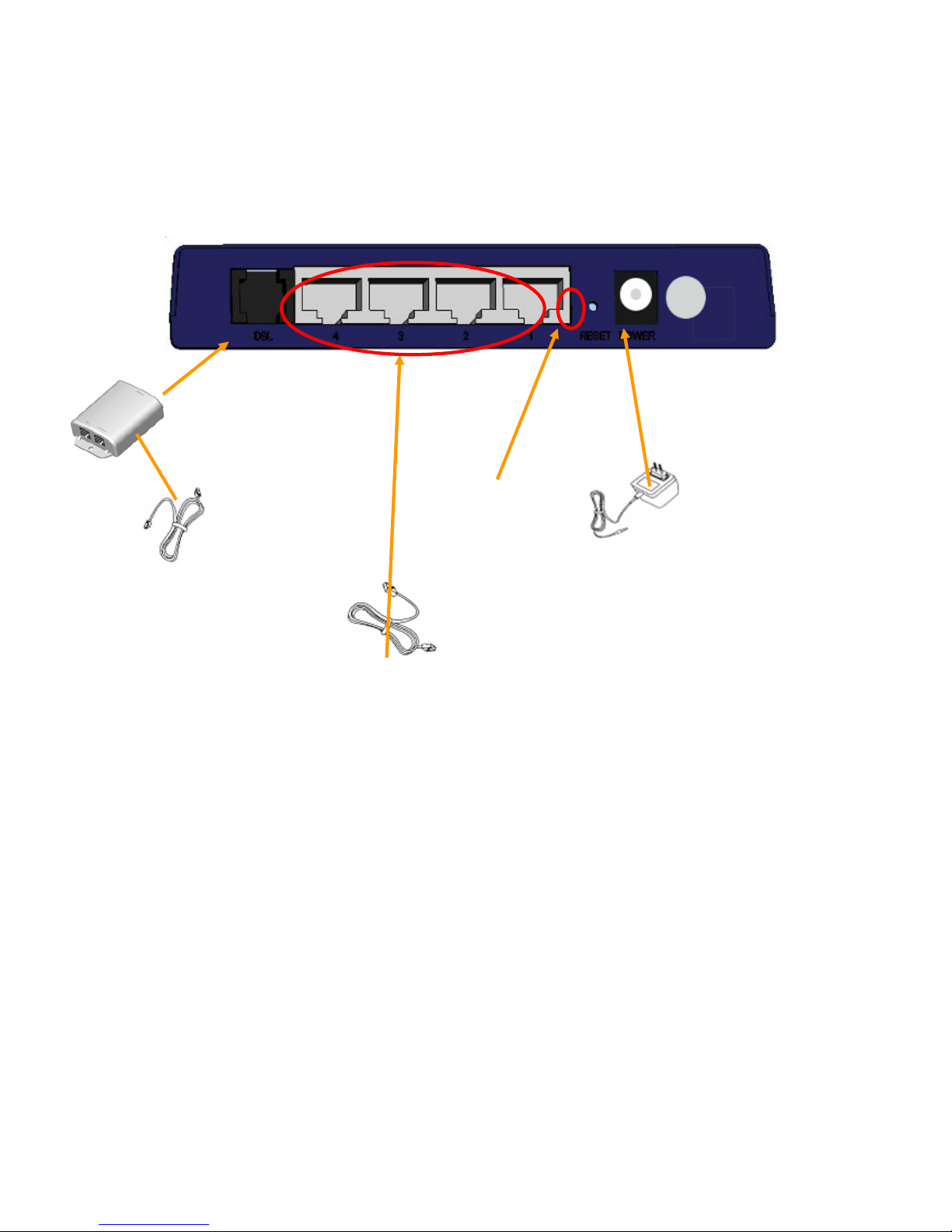
3. Hardware Connecting
Wireless 11g ADSL Router
Factory Reset button
RJ-11 ADSL port connect
ADSL cable here
RJ-45 Ethernet port connect
Ethernet cable here
Splitter (optional and
changes depending on
country specification)
Power Adapter (7.5VAC/1A)
Power cord connect here
5
Page 7
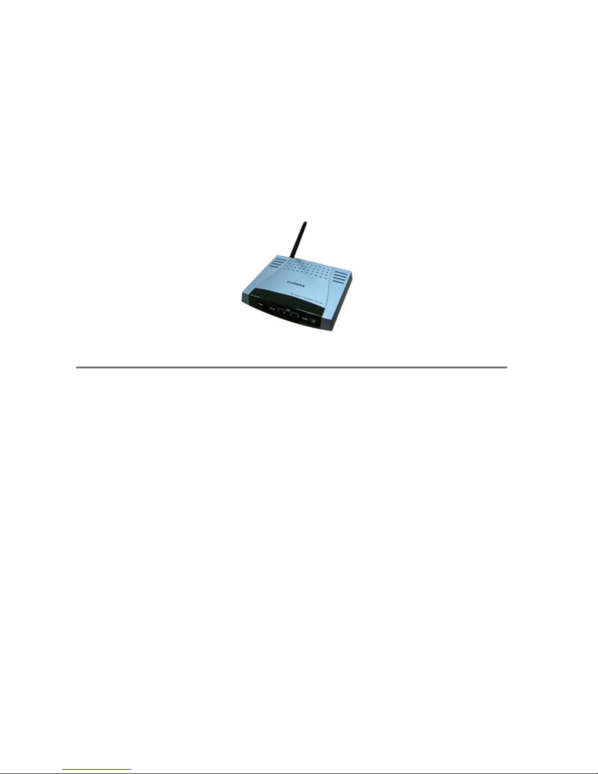
4. LED Indicators
The LED Indicators are located on the front of the unit, they are green in color. The
meanings are as follows:
1. Wireless 11g ADSL Router
Label Meaning Status Indicates
Power Power On Power is on
Off Power is off
WLAN Wireless LAN Flashing Check wireless device.
ADSL Link Link A valid ADSL connection.
Active Act An active WAN session.
Link/Act Link On Indicates a link to your LAN or Network
card is active.
Active Flashing Flashes when data is being sent or
received on the LAN connection.
6
Page 8
5. General Setting
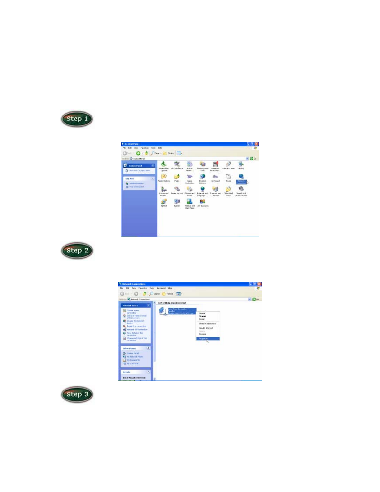
You can use the RJ 45 cable or the USB cable connect to the ADSL Wireless Router. If
you use the USB cable connect to the ADSL Wireless Router, about the USB driver install
steps please see as chapter “USB Driver Procedure”.
Move your cursor as following sequence Start \ Settings \ Control Panel
and click Control Panel. Then double-click on the Network Connections
In the LAN or High-Speed Internet window, right-click on icon
corresponding to your network interface card (NIC) and select Properties.(This icon
may be labeled Local Area Connection).
In the General Tab of the Local Area Connection Properties menu.
Highlight Internet Protocol (TCP/IP) under “This connection uses the following
items.” by click on it once. Click on the Properties button.
7
Page 9
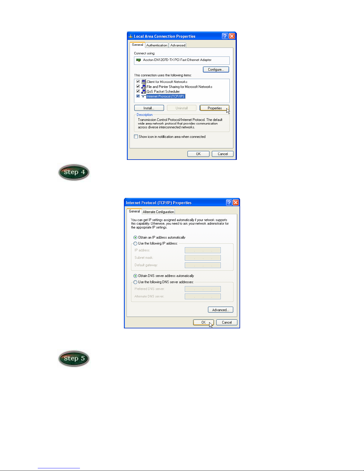
Select Obtain an IP Address automatically: by clicking once in the circle.
Click OK button to confirm and save your changes, and the close the Control Panel.
Release IP & Renew IP, then Check Default Gateway: 192.168.1.1.
8
Page 10
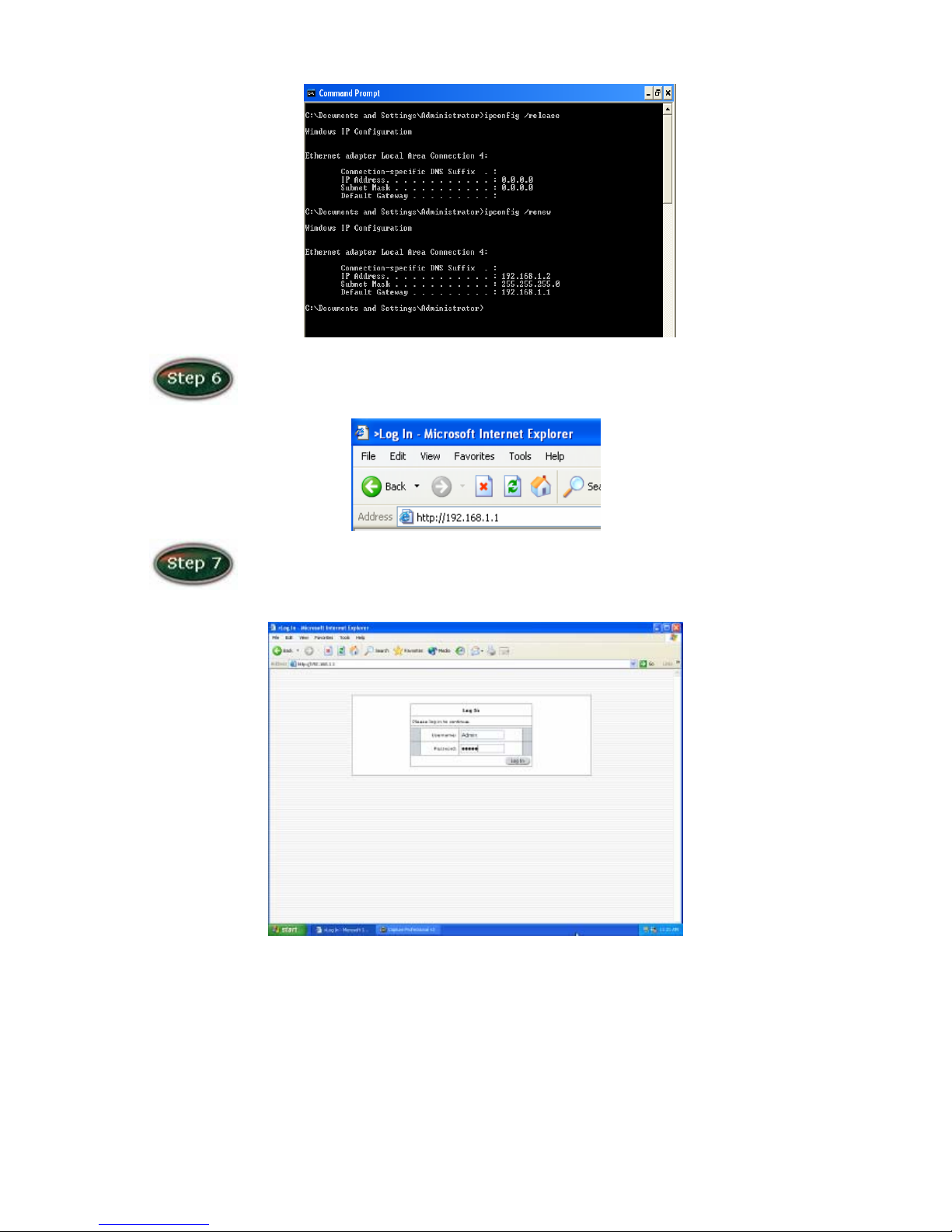
Launch your PC web browser and enter the URL: http://192.168.1.1
In the User name/Password prompt, please type in Admin/Admin as
default.
9
Page 11
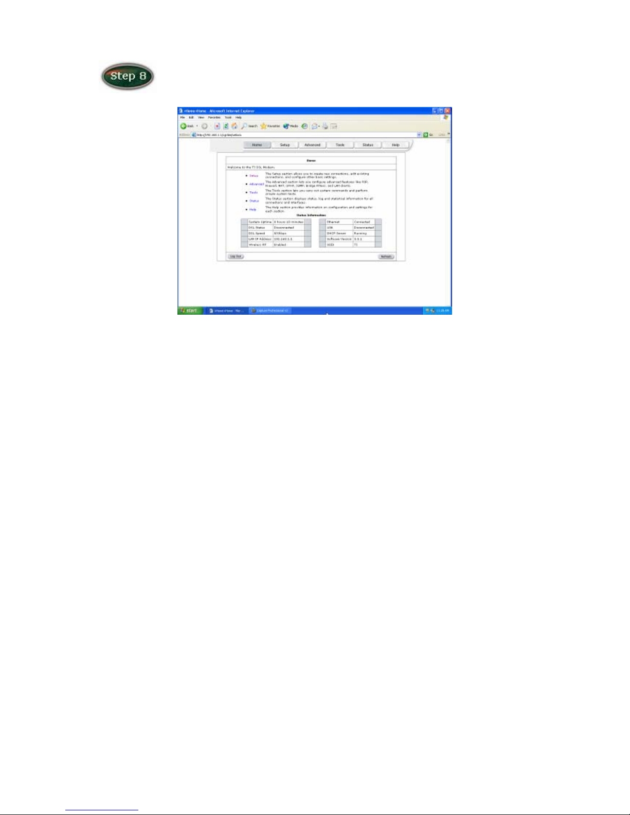
Please wait for the Home page to appear.
10
Page 12
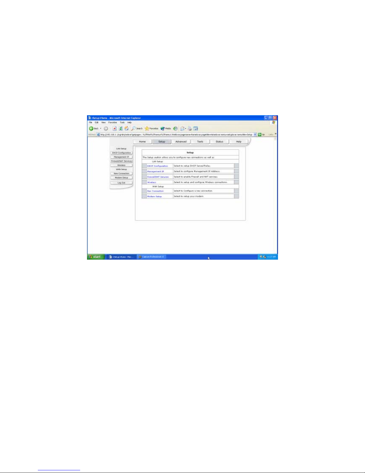
6. Advanced Setting
(1) Setup
The following is displayed LAN Setup and WAN Setup.
11
Page 13
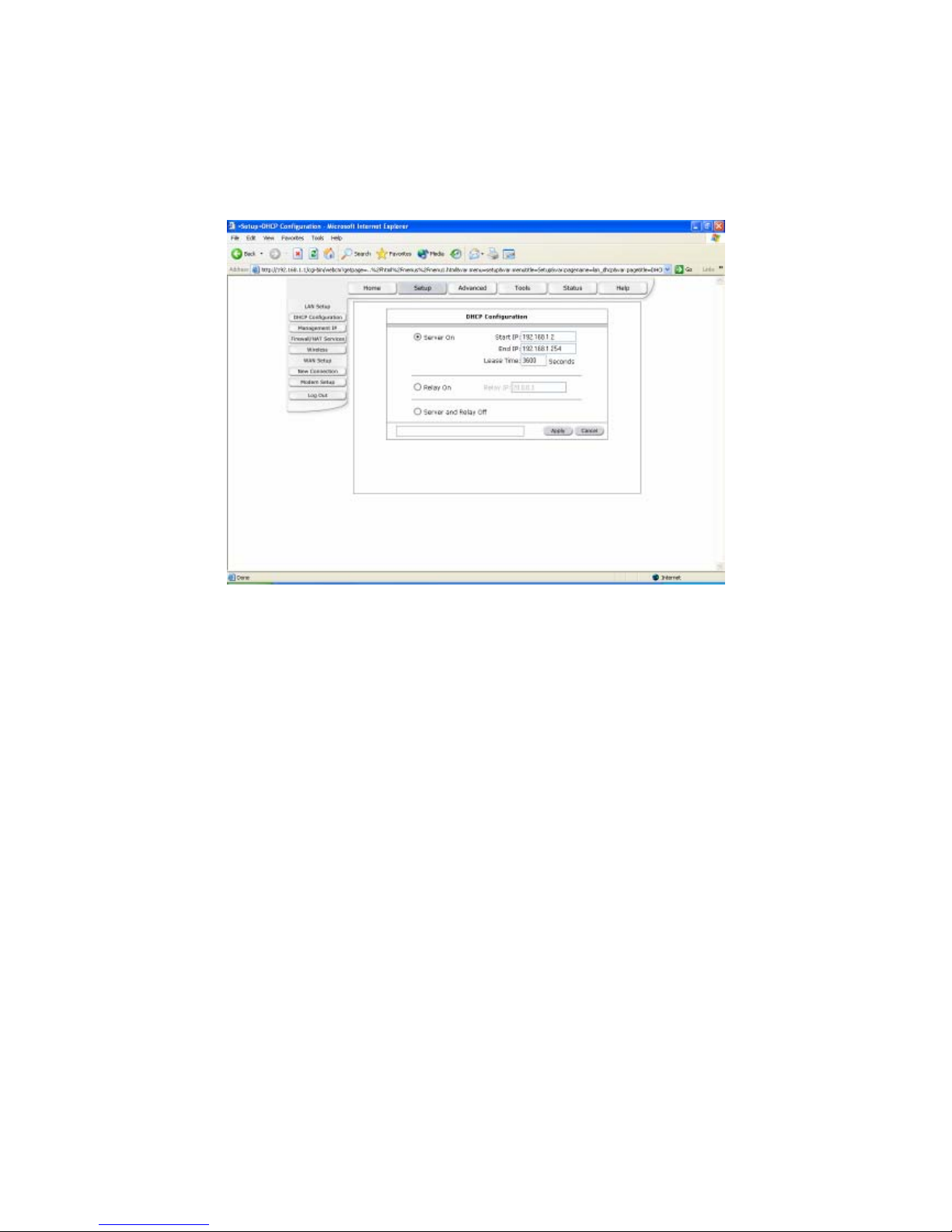
DHCP Configuration
DHCP stands for Dynamic Host Configuration Protocol. It can automatically dispatch
related IP settings to any local user configured as a DHCP client.
Server On: Enables the DHCP server.
Start IP: Sets the start IP address of the IP address pool.
End IP: Sets the end IP address of the IP address pool.
Lease time: The lease time is the amount of time of a network user will be allowed to
connect with DHCP server. If all fields are 0, the allocated IP address will be effective
forever.
Relay On: Allow PCs on LAN to request IP from other DHCP server.
Relay IP: Sets the other DHCP server IP address.
12
Page 14
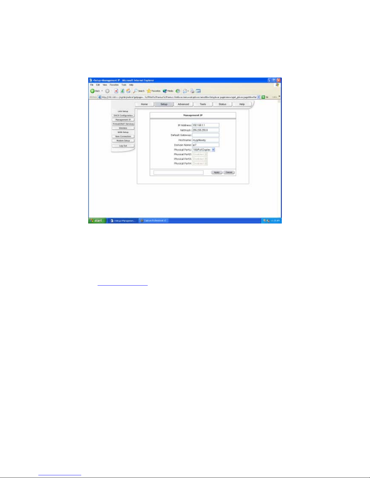
Management IP
The Management IP page shows the ADSL physical layer status.
IP Address: Private IP address for connecting to a local private network (Default:
192.168.1.1).
Netmask: Netmask for the local private network (Default: 255.255.255.0).
Default Gateway: This field is optional. Enter in the IP address of the router on your
network.
Host Name: Required by some ISPs. If the ISP does not provide the Host name, please
leave it blank.
Domain Name:
www.dynsns.org will provide you with a Domain Name. Enter this name in
the “Domain Name” field.
Physical Port: There are five kinds of mode for data transfer (Auto)(10/Half
Duplex)(10/Full Duplex)(100/Half Duplex)(100/Full Duplex).
Apply: Click Apply to save the changes.
13
Page 15
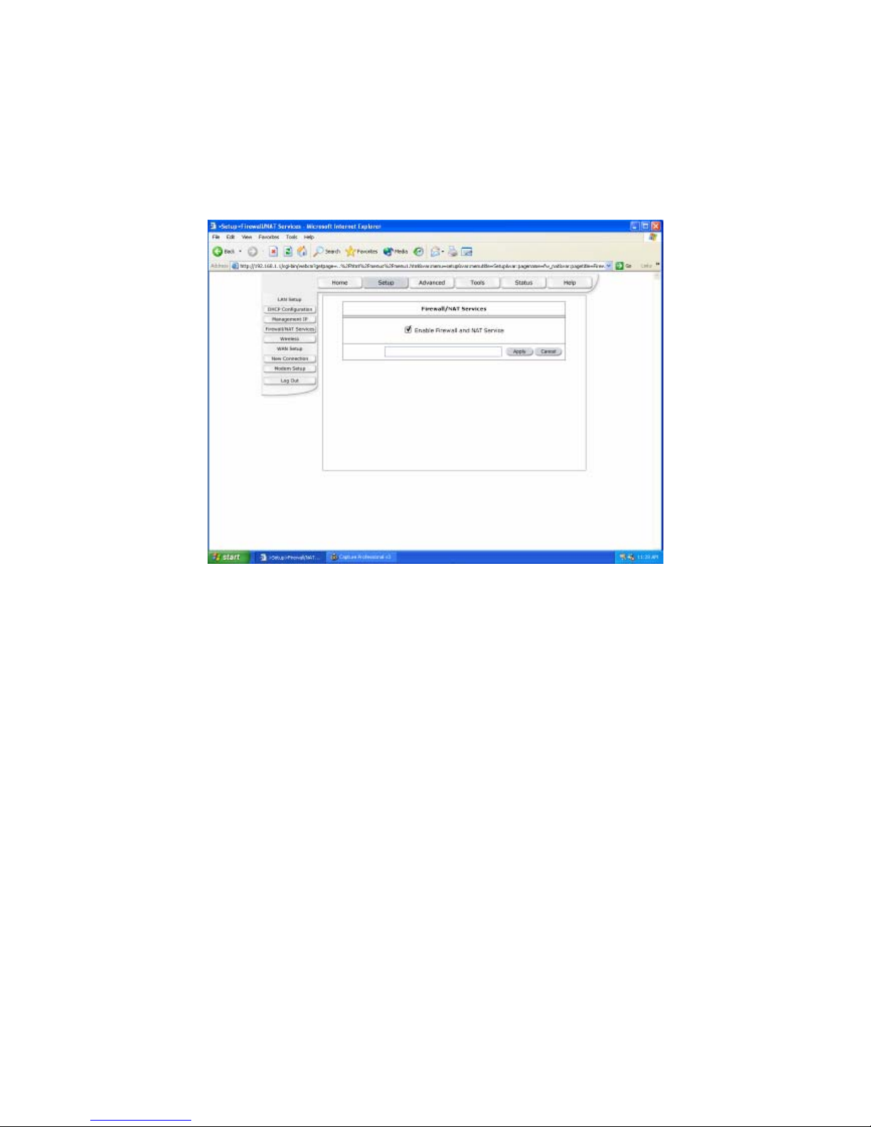
Firewall/NAT Services
Network Address Translation (NAT): Is a method of mapping one or more IP addresses
and/or IP service ports into different specified values.
Firewall: In addition to the built-in NAT mechanism.
Firewall/NAT Services: Select Enable to turn on the Firewall/NAT Service.
Apply: Click Apply to save the changes.
14
Page 16
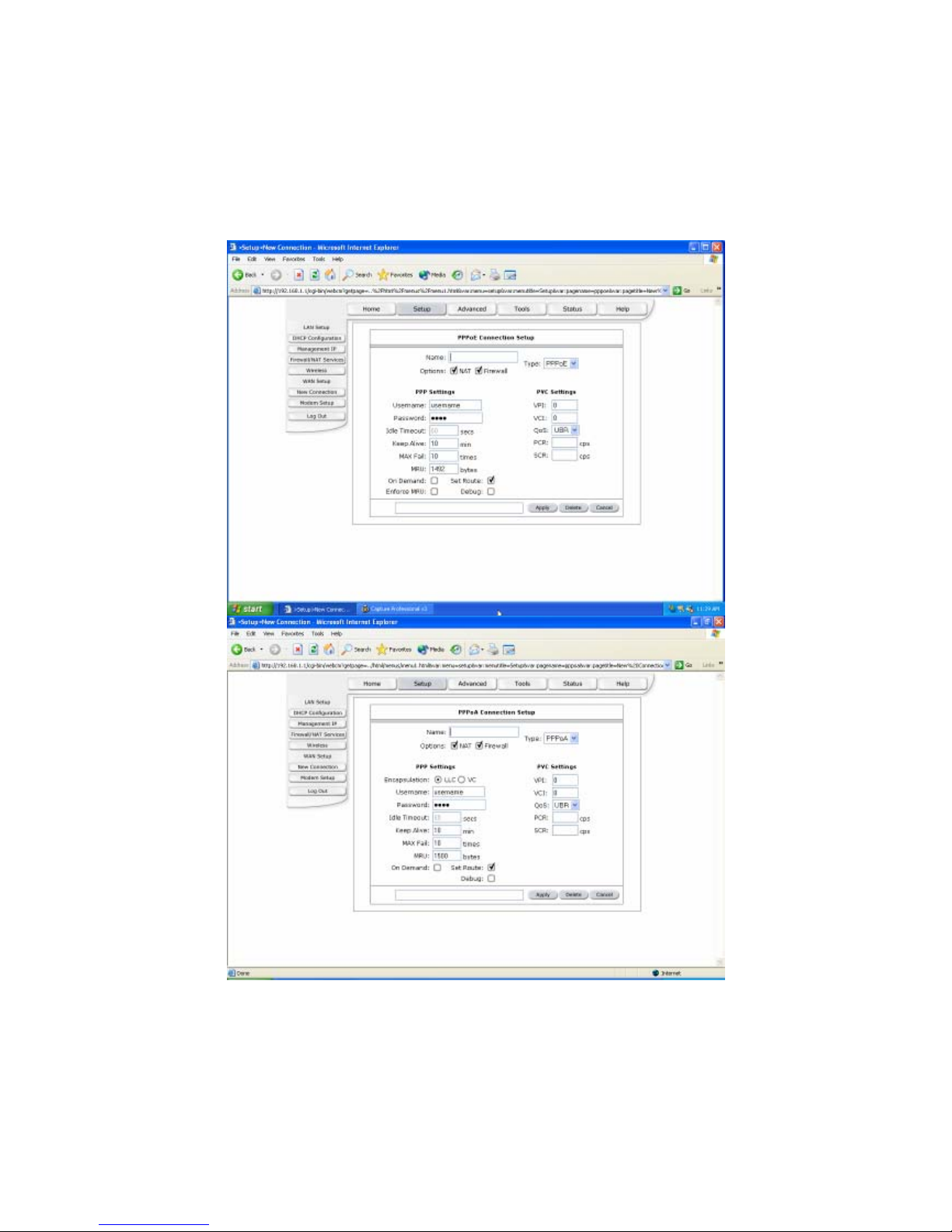
New Connection
When working with wide area connections, the first thing you must do is to have the handle
of the connection. Once you have the handle for a Connection you must define the PVC
and protocol settings for it.
15
Page 17
16
Page 18
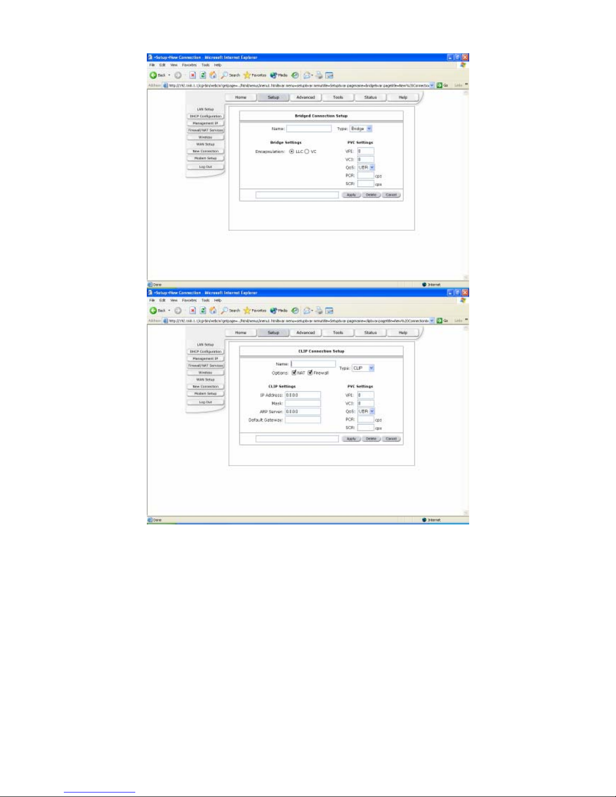
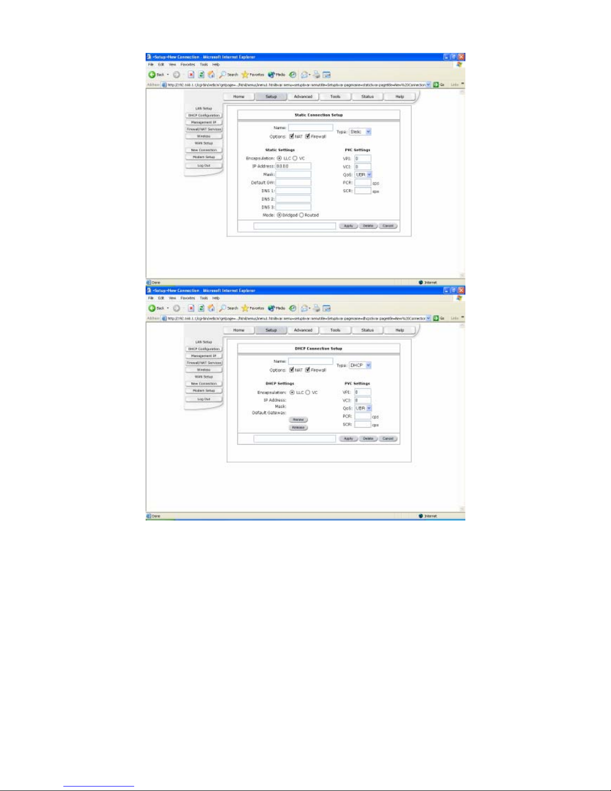
Name: Enter the name of your ISP. This information is for identification purposes only.
Type: There six kinds of method (PPPoE/PPPoA/Static/DHCP/Bridge/CLIP).
PPP Settings
Encapsulation: Select the method of encapsulation used by your ISP from the drop-down
list box. Choices vary depending on the mode you select in the Mode field.
Username: Enter the username provided by your ISP.
Password: Enter the password provided by your ISP.
Idle Timeout: Idle timeout means the router will disconnect after being idle for a preset
amount of time. The default is 60 seconds. If you set the time to 0, the ISDN
connection will remain always connected to the ISP.
Keep Alive: If mode is LCP, This is the Keep Alive timer. If a reply to the LCP echo is not
received in this amount if time, the connection is dropped. The Default is 10.
MAX Fail: Number of times the connection is tried before giving up if it can’t be connected.
The Default is 10.
MRU: Maximum Receive Unit indicates the peer of PPP connection the maximum size of
the PPP information field this device can be received. The default value is 1492 and is
17
Page 19

used in the beginning of the PPP negotiation. In the normal negotiation, the peer will
accept this MRU and will not send packet with information field larger than this value.
Static Settings
Encapsulation: Select the method of encapsulation used by your ISP from the drop-down
list box. Choices vary depending on the mode you select in the Mode field.
IP Address: Private IP address for connecting to a local private network (Default:
192.168.1.1).
Netmask: Netmask for the local private network (Default: 255.255.255.0).
Default Gateway: This field is optional. Enter in the IP address of the router on your
network.
DNS: Sets the IP address of the DNS server.
Mode: Bridged and Routed
DHCP Settings
Encapsulation: Select the method of encapsulation used by your ISP from the drop-down
list box. Choices vary depending on the mode you select in the Mode field.
IP Address: Private IP address for connecting to a local private network (Default:
192.168.1.1).
Netmask: Netmask for the local private network (Default: 255.255.255.0).
Default Gateway: This field is optional. Enter in the IP address of the router on your
network.
Bridge Settings
Encapsulation: Select the method of encapsulation used by your ISP from the drop-down
list box. Choices vary depending on the mode you select in the Mode field.
CLIP Settings
IP Address: Private IP address for connecting to a local private network (Default:
192.168.1.1).
Netmask: Netmask for the local private network (Default: 255.255.255.0).
ARP Server: Translating an IP address to an ATM address.
Default Gateway: This field is optional. Enter in the IP address of the router on your
network.
PVC Settings
VPI: If instructed to change this, type in the VPI value for the initial connection (using PVC
0). Default = 0.
VCI: If instructed to change this, type in the VCI value for the initial connection (using PVC
0). Default = 0.
QoS: Quality of Service type. Select CBR (Continuous Bit Rate) to specify fixed (always-
on) bandwidth for voice or data traffic. Select UBR (Unspecified Bit Rate) for
applications that are non-time sensitive, such as e-mail. Select VBR (Variable Bit
Rate) for burst traffic and bandwidth sharing with other applications.
PCR: Divide the DSL line rate (bps) by 424 (the size of an ATM cell) to find the Peak Cell
Rate (PCR). This is the maximum rate at which the sender can send cells.
SCR: The Sustain Cell Rate (SCR) sets the average cell rate (long-term) that can be
transmitted.
Apply: Click Apply to save the changes.
18
Page 20
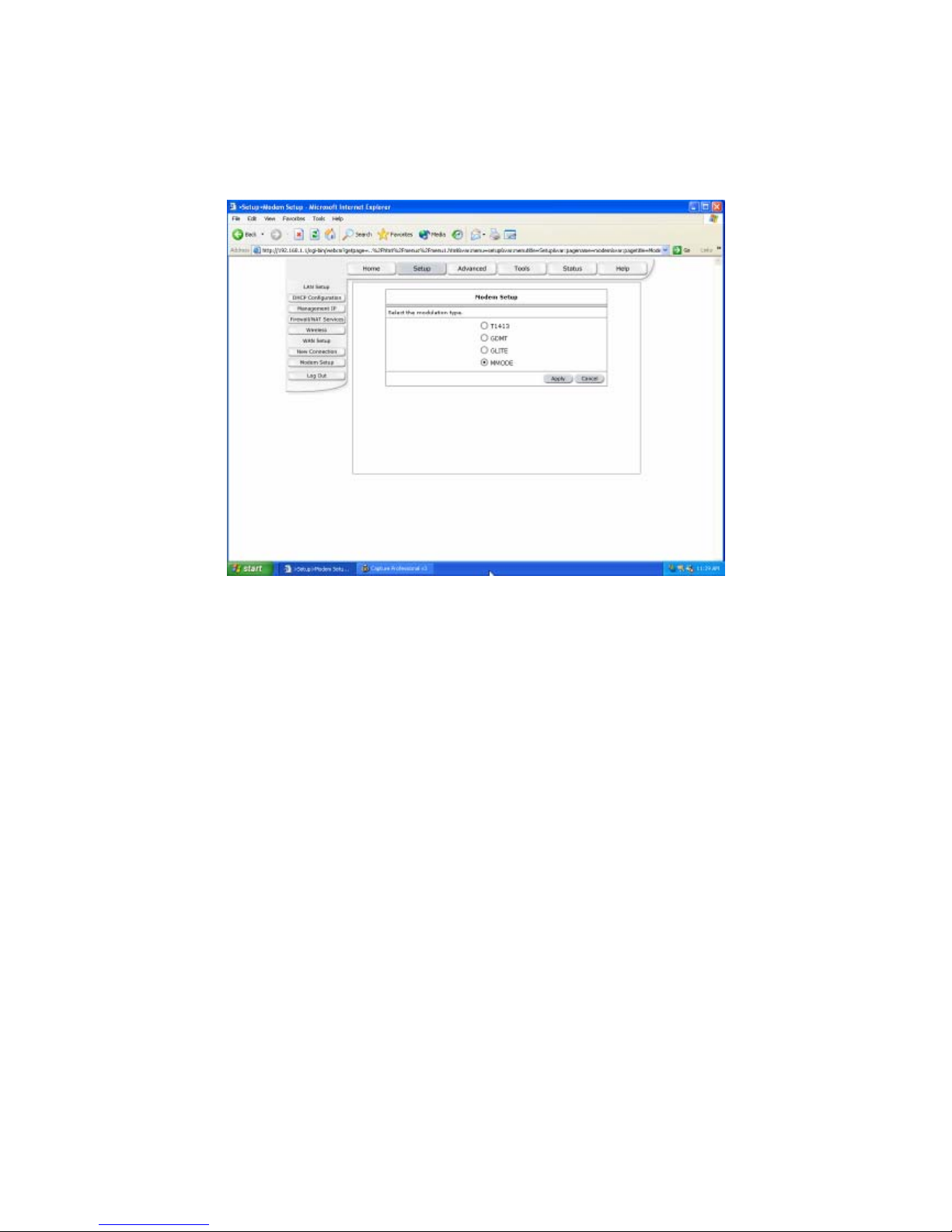
Modem Setup
Select ADSL Transmission Rate.
T1413: Full-Rate (ANSI T1.413 Issue 2) with line rate support of up to 8 Mbps downstream
and 832 Kbps upstream.
GDMT: Full-Rate (G.dmt, G992.1) with line rate support of up to 8 Mbps downstream and
832 Kbps upstream.
GLITE: G.lite (G.992.2) with line rate support of up to 1.5 Mbps downstream and 512 Kbps
upstream.
MMODE: Support Multi-Mode standard (ANSI T1.413 Issue 2; G.dmt(G.992.1);
G.lite(G.992.2)).
Apply: Click Apply to save the changes.
19
Page 21
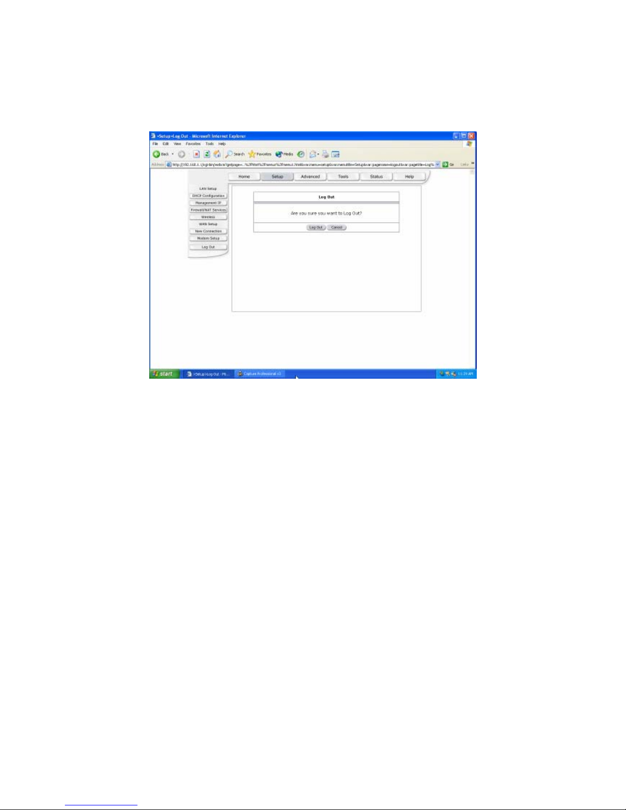
Log Out
Log the user out of the web pages.
20
Page 22
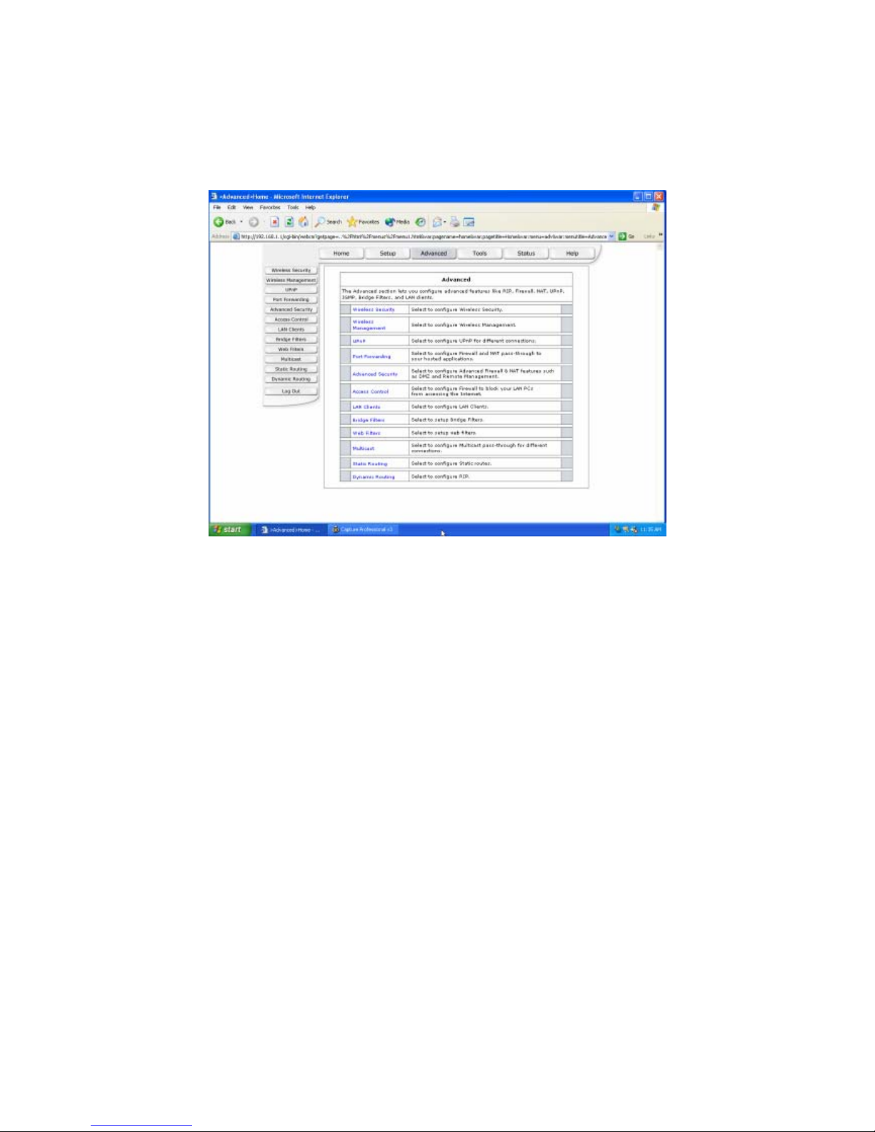
(2) Advanced
The Advanced section lets you configure advanced features like RIP, Firewall, NAT, UPnP,
IGMP, Bridge Filters, and LAN clients.
21
Page 23
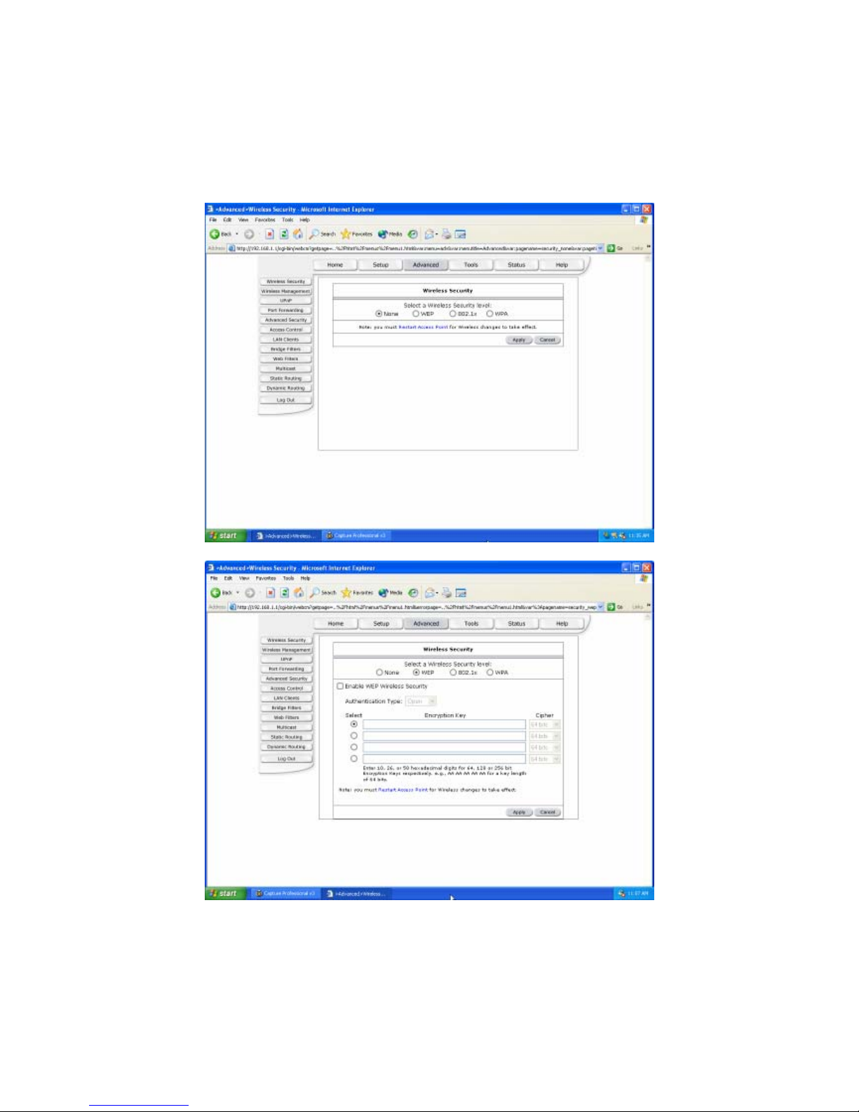
Wireless Security
Select a Wireless Security level
None: Disable Wireless encryption.
WEP: WEP encryption scrambles the data transmitted between the wireless stations and
the access points to keep network communications private. It encrypts unicast and
multicast communications in a network. Both the wireless stations and the access
points must use the same WEP key for data encryption and decryption.
22
Page 24
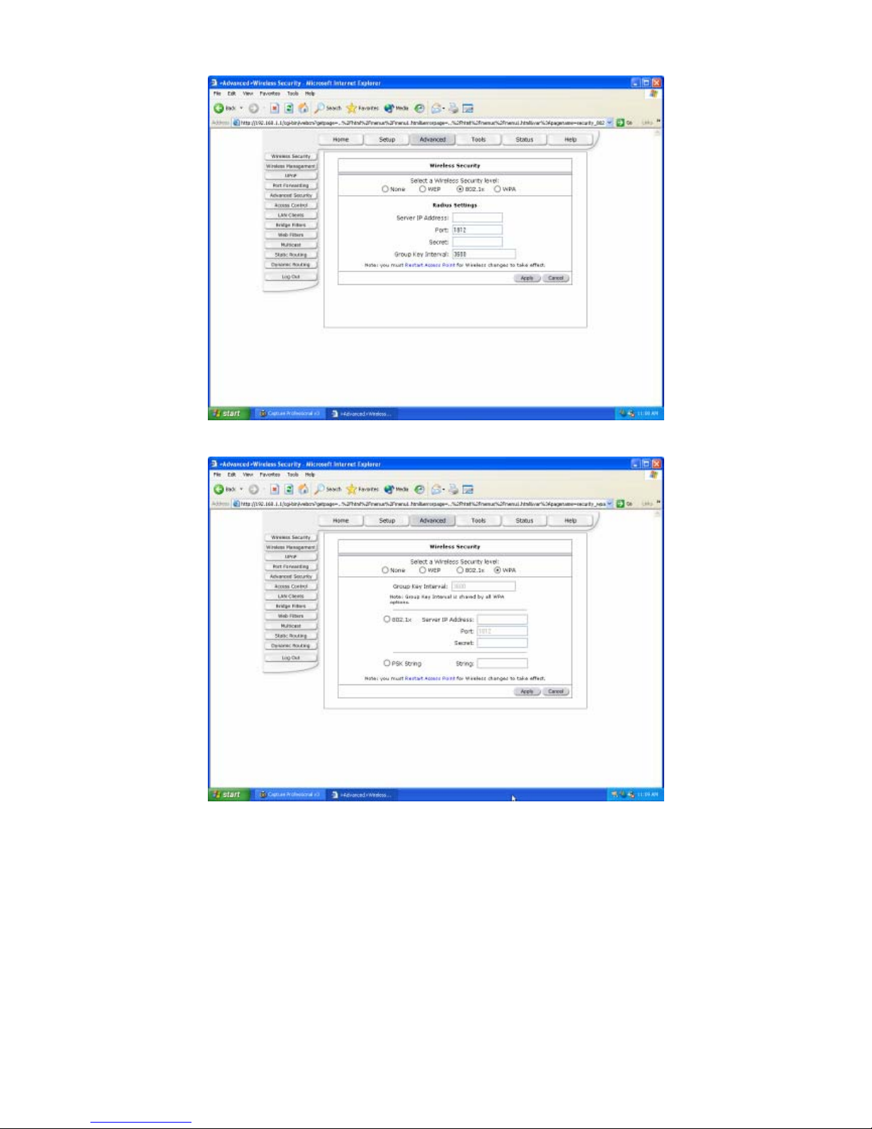
802.1x: The IEEE 802.1x standards outline enhanced security methods for both the
authentication of wireless stations and encryption key management.
WPA: Wi-Fi Protected Access (WPA) is a subset of the IEEE 802.11i security specification
draft. Key differences between WPA and WEP are user authentication and improved
data encryption.
Apply: Click Apply to save the changes.
23
Page 25
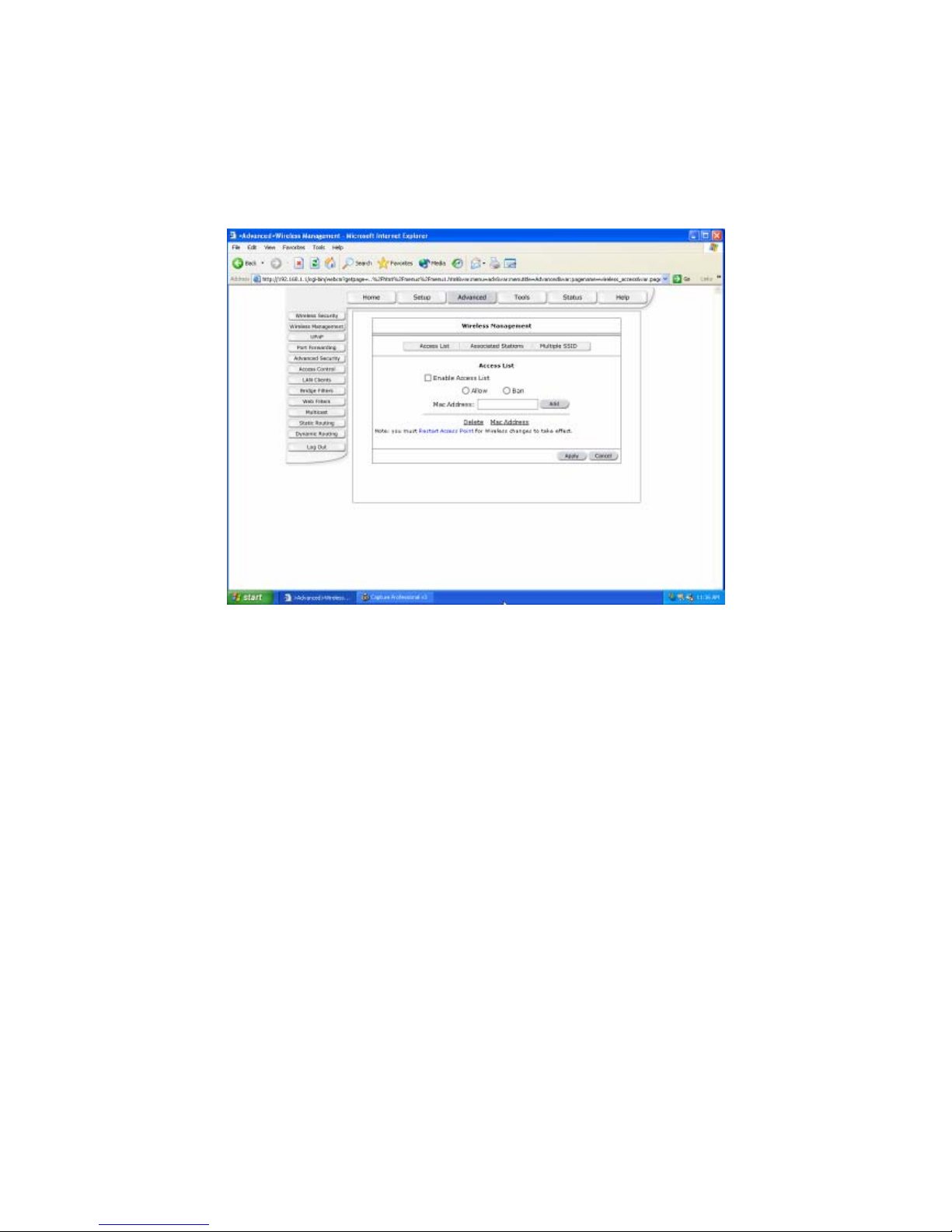
Wireless Management
The Wireless Management page allows your prestige can check the MAC addresses of
Wireless stations against a list of allowed or denied MAC addresses.
Enable Access List: Enable the Wireless Management by Access List.
MAC Address: Enter the MAC Address.
Apply: Click Apply to save the changes.
24
Page 26
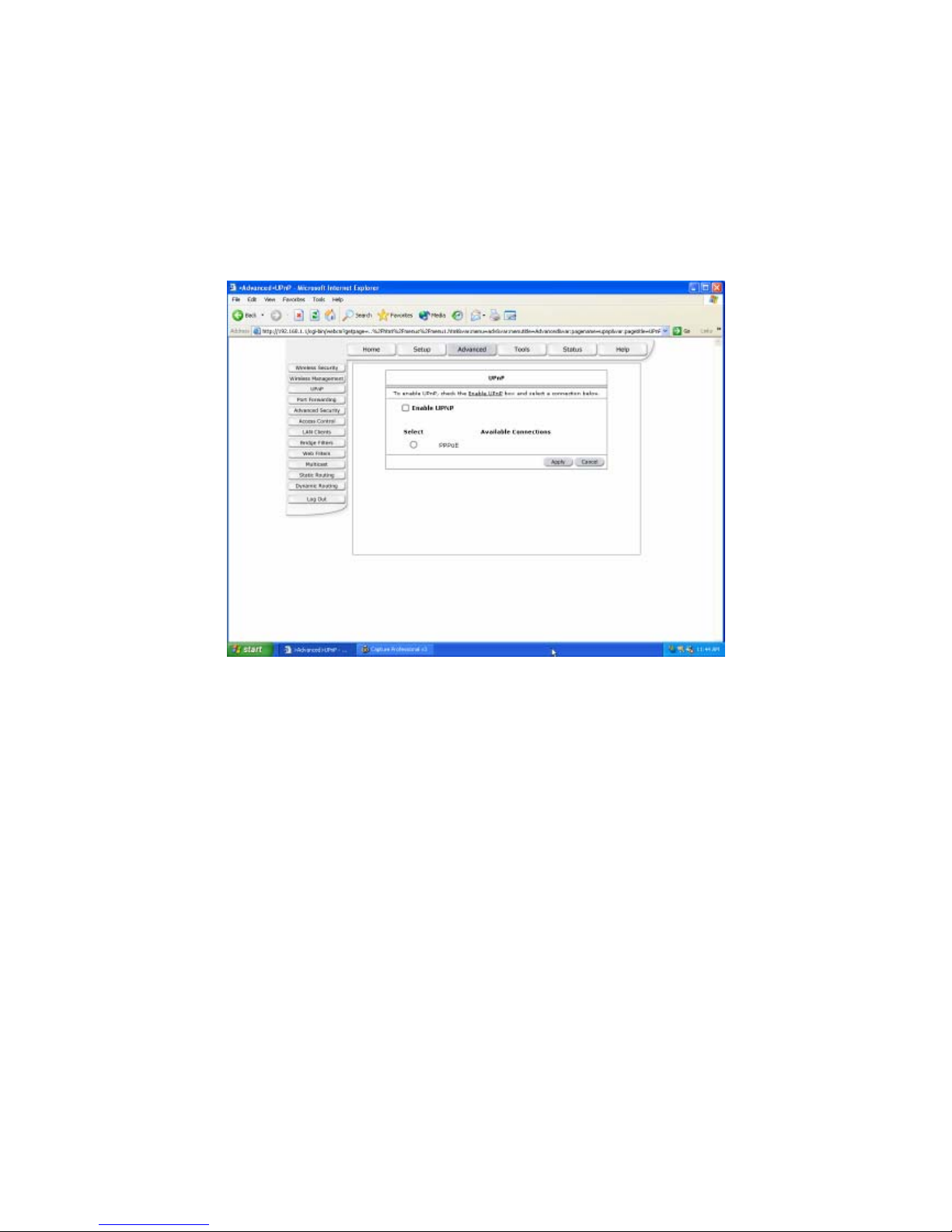
UPnP
Universal Plug and Play (UPnP) is a distributed, open networking standard that uses
TCP/IP for simple peer-to –peer network connectivity between devices a UPnP device can
dynamically join a network, obtain and IP address, convey is capabilities and learn about
other devices on the network. In turn, a device can leave a network smoothly and
automatically when it is no longer in use.
Enable UPNP: Enable the UPnP.
Apply: Click Apply to save the changes.
25
Page 27
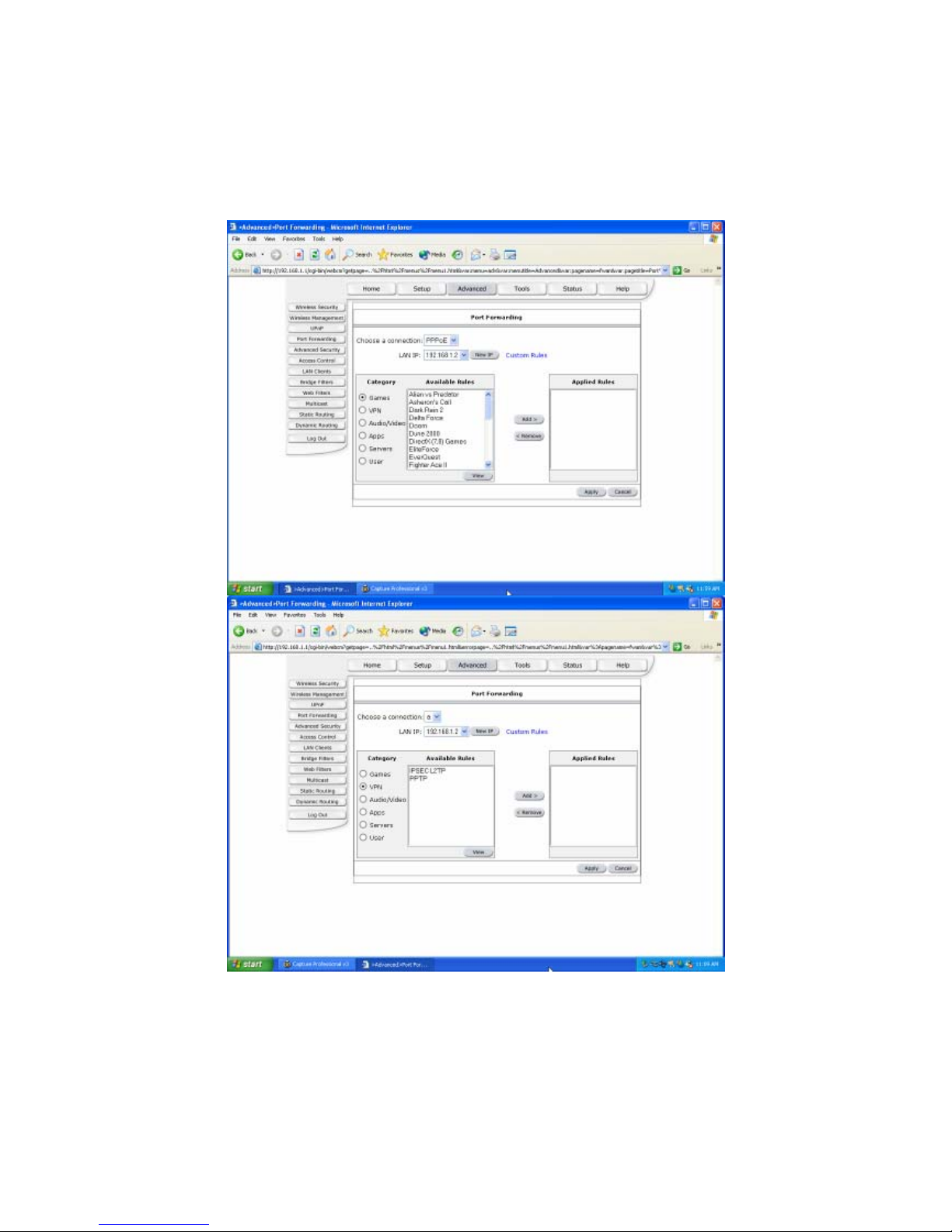
Port Forwarding
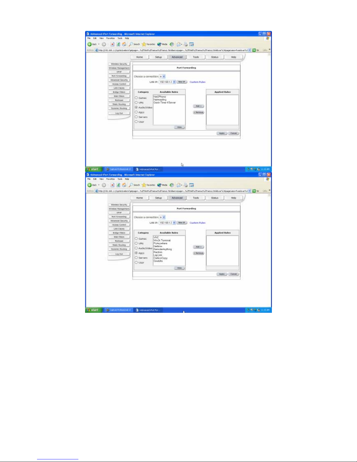
The Port Forwarding page allows the user define a port forwarding rule without using the
firewall policy database definitions and apply it to the connection.
26
Page 28
27
Page 29
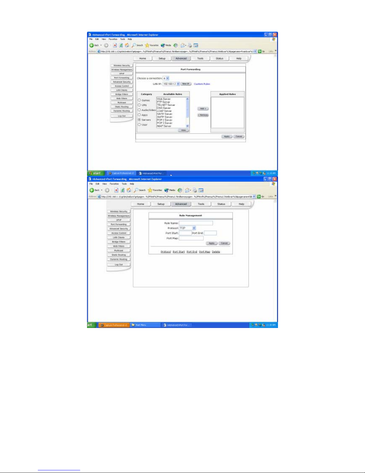
Choose a connection: You can choose a connection to do this.
LAN IP: type your LAN IP. For example 192.168.1.2.
Apply: Click Apply to save the changes.
28
Page 30
Advanced Security
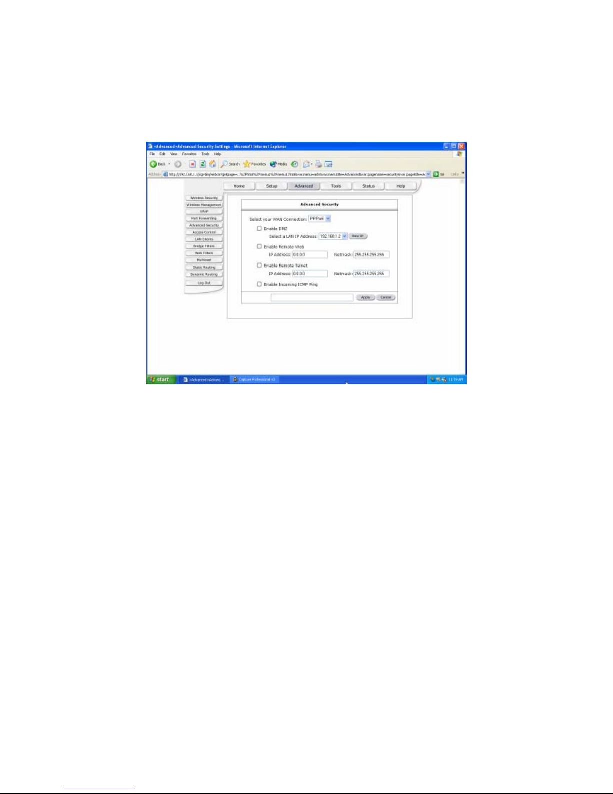
The Advanced Security page provides advanced rules that can be applied to a particular
Connection.
Enable DMZ: Enable or Disable DMZ.
Enable Remote Web: Allow or deny incoming access to the modems Web pages
remotely.
Enable Remote Telnet: Allow or deny incoming access to the modems Telnet Interface
remotely.
Enable Incoming ICMP Ping: Allow or deny incoming Pings to the Modem.
Apply: Click Apply to save the changes.
29
Page 31
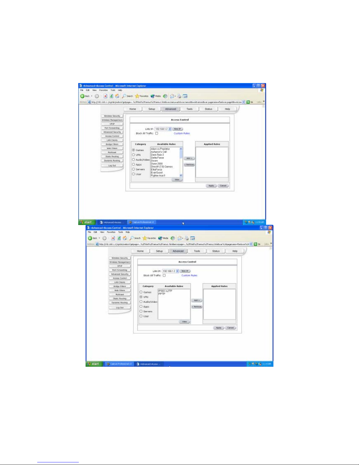
Access Control
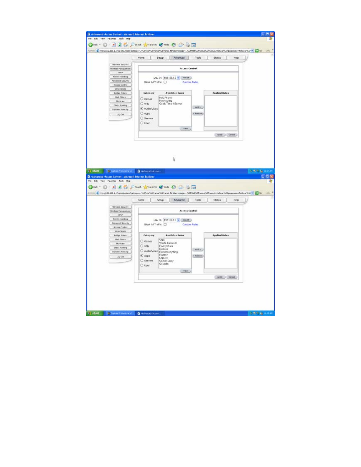
Access Control allows users to define the outgoing traffic permitted or denied access
through the WAN interface. The default is to permit all outgoing traffic.
30
Page 32
31
Page 33
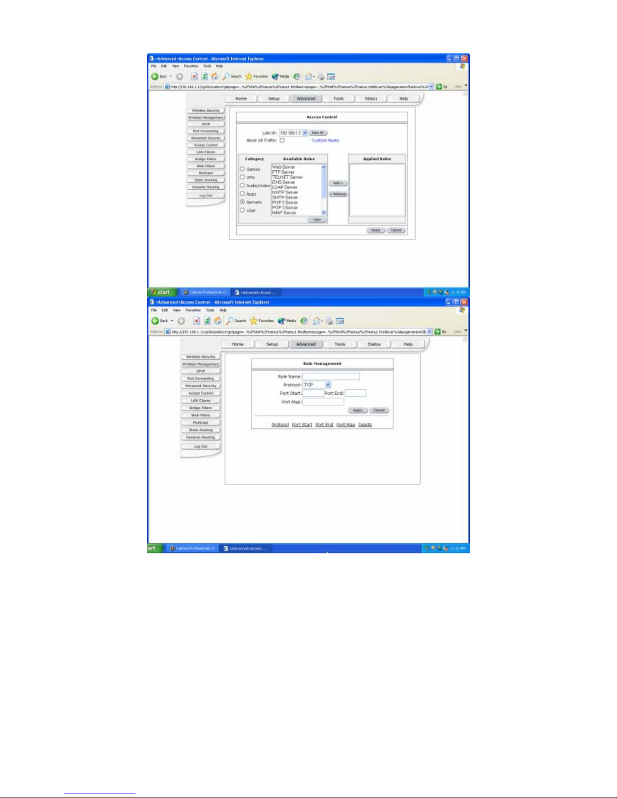
Apply: Click Apply to save the changes.
32
Page 34
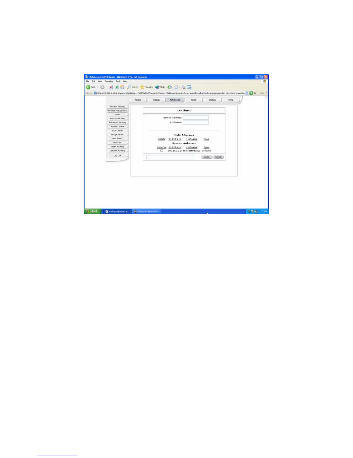
LAN Clients
The LAN Clients page allows you to set the configuration for the LAN port.
New IP Address: Enter the IP Address.
Hostname: Enter the Hostname.
Apply: Click Apply to save the changes.
33
Page 35
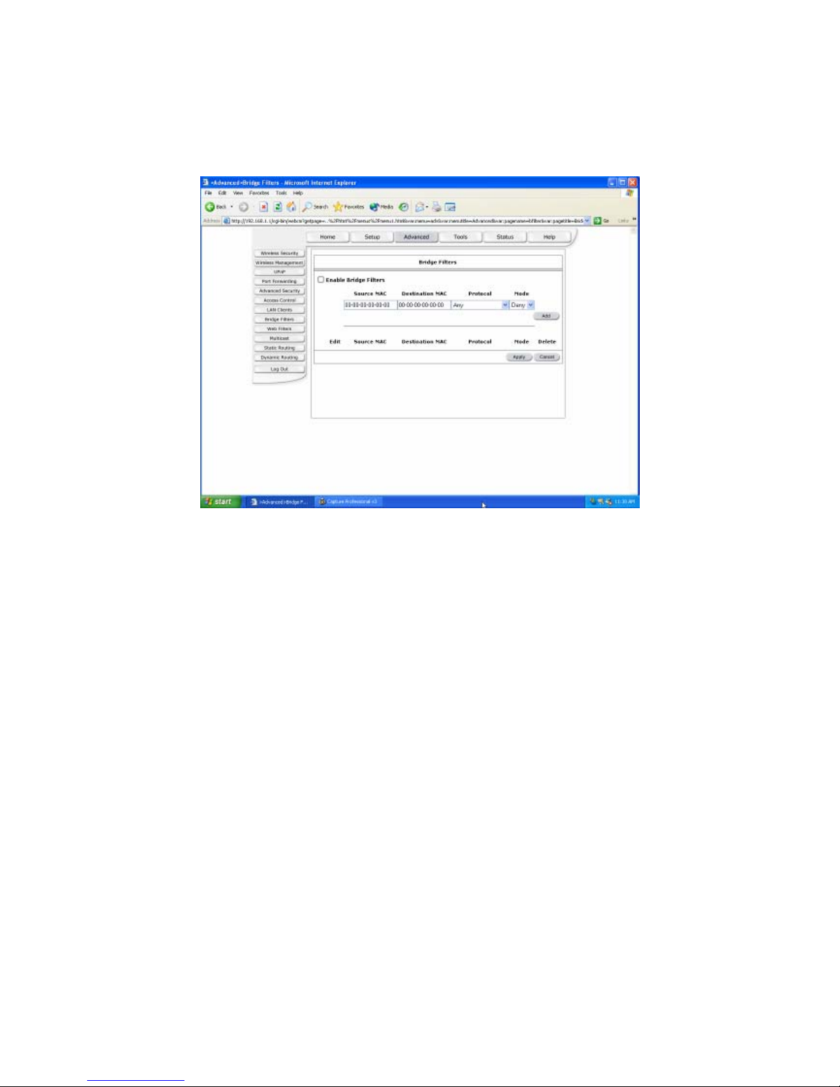
Bridge Filters
The bridge filtering page allows users to set the configuration of IP filtering.
Source MAC: When the bridge filtering is enabled, enter the Source MAC address, select
Block and click Add. Then all incoming WAN and LAN Ethernet packets matched
with this source MAC address will be filtered out. If the Forward is selected, then the
packets will be forwarded to the destination PC.
Destination MAC: When the bridge filtering is enabled, enter the Destination MAC
address, select Block and click Add. Then all incoming WAN and LAN Ethernet
packets matched with this destination MAC address will be filtered out. If the Forward
is selected, then the packets will be forwarded to the destination PC.
Type: Enter the hexadecimal number for the Ethernet type field in Ethernet_II packets. For
example, 0800 is for IP protocol.
Apply: Click Apply to save the changes.
34
Page 36
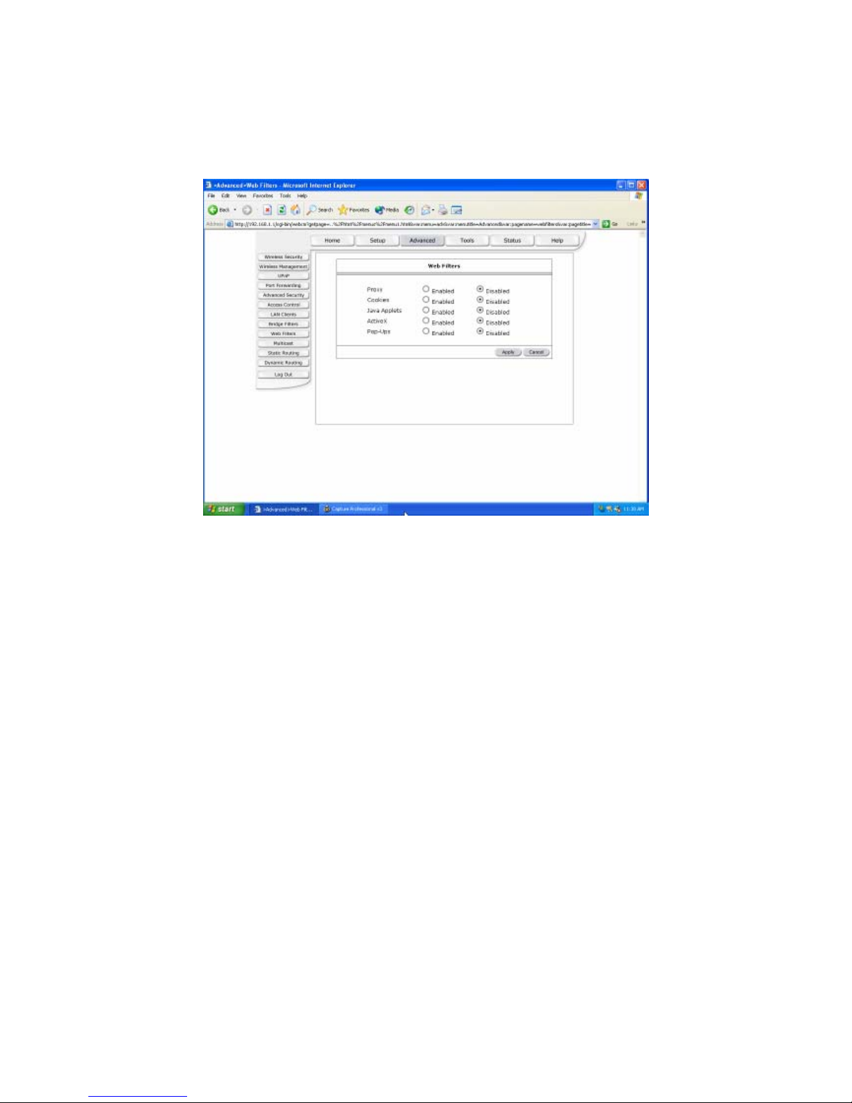
Web Filters
The following queries manage the Content Filtering capabilities of the NSP.
Apply: Click Apply to save the changes.
35
Page 37
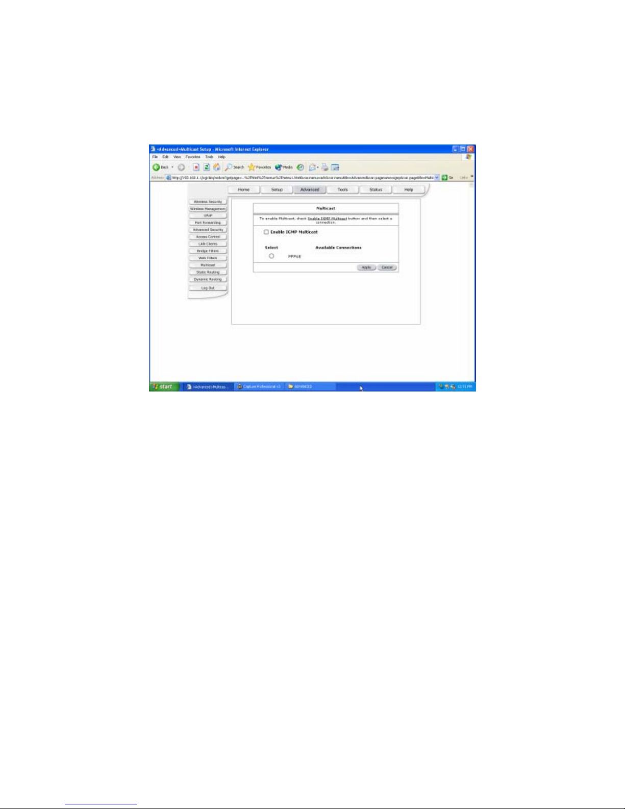
Multicast
The NSP is capable of proxying for applications that are using multicast IP for accessing
Video content. This application needs to be run when NAT is enabled.
Apply: Click Apply to save the changes.
36
Page 38
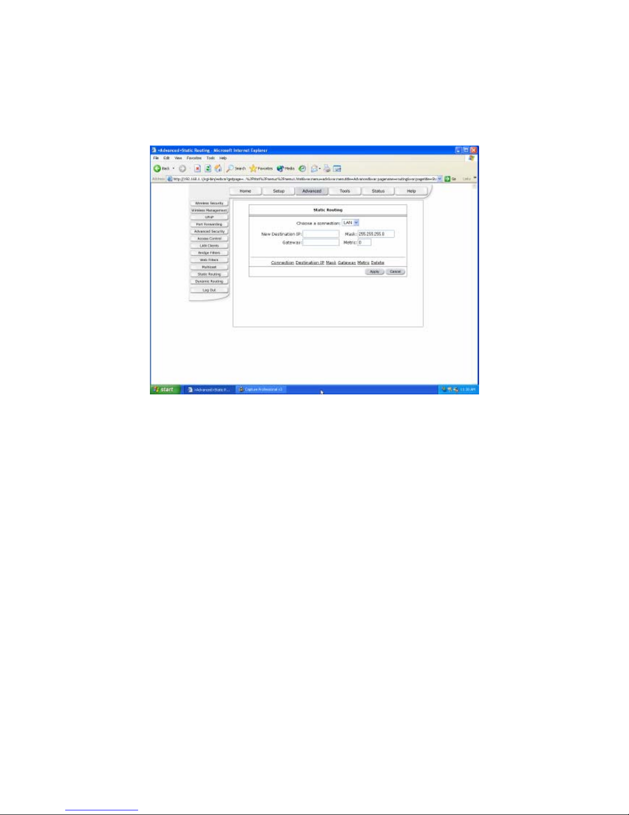
Static Routing
The following queries manage the RIP routing application and static routing entries for the
NSP. The RIP application supports both version 1 and 2.
New Destination IP: Enter the New Destination IP.
Gateway: Enter the IP Address of the Gateway.
Apply: Click Apply to save the changes.
37
Page 39
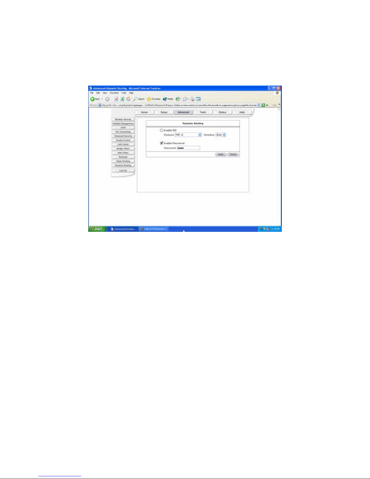
Dynamic Routing
The following queries manage the RIP routing application and static routing entries for the
NSP. The RIP application supports both version 1 and 2.
Apply: Click Apply to save the changes.
38
Page 40
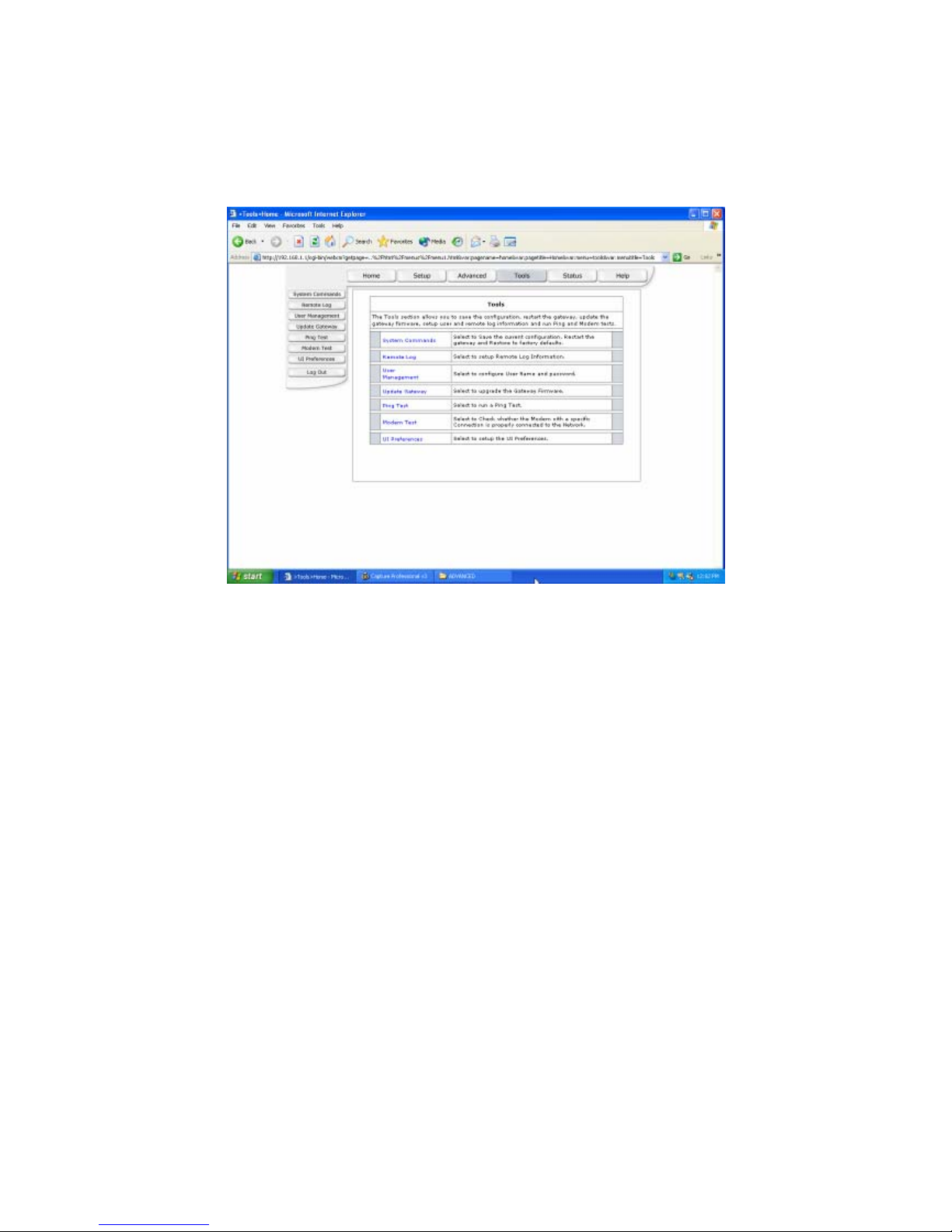
(3) Tools
The Tools section allows you to save the configuration, restart the gateway, update the
gateway firmware, setup user and remote log information and run Ping and Modem tests.
39
Page 41
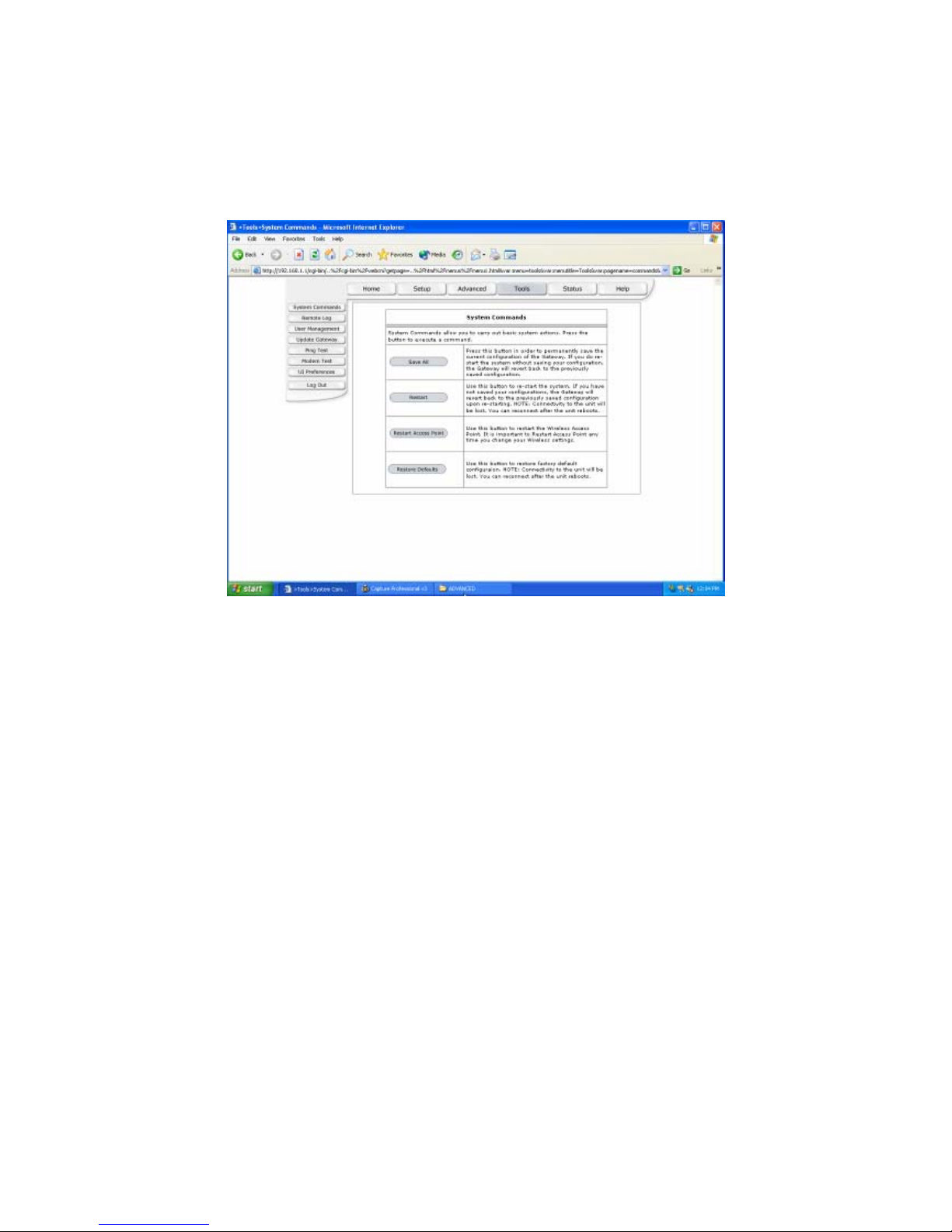
System Commands
System commands allow you to carry out basic system actions. Press the button to
execute a command.
40
Page 42
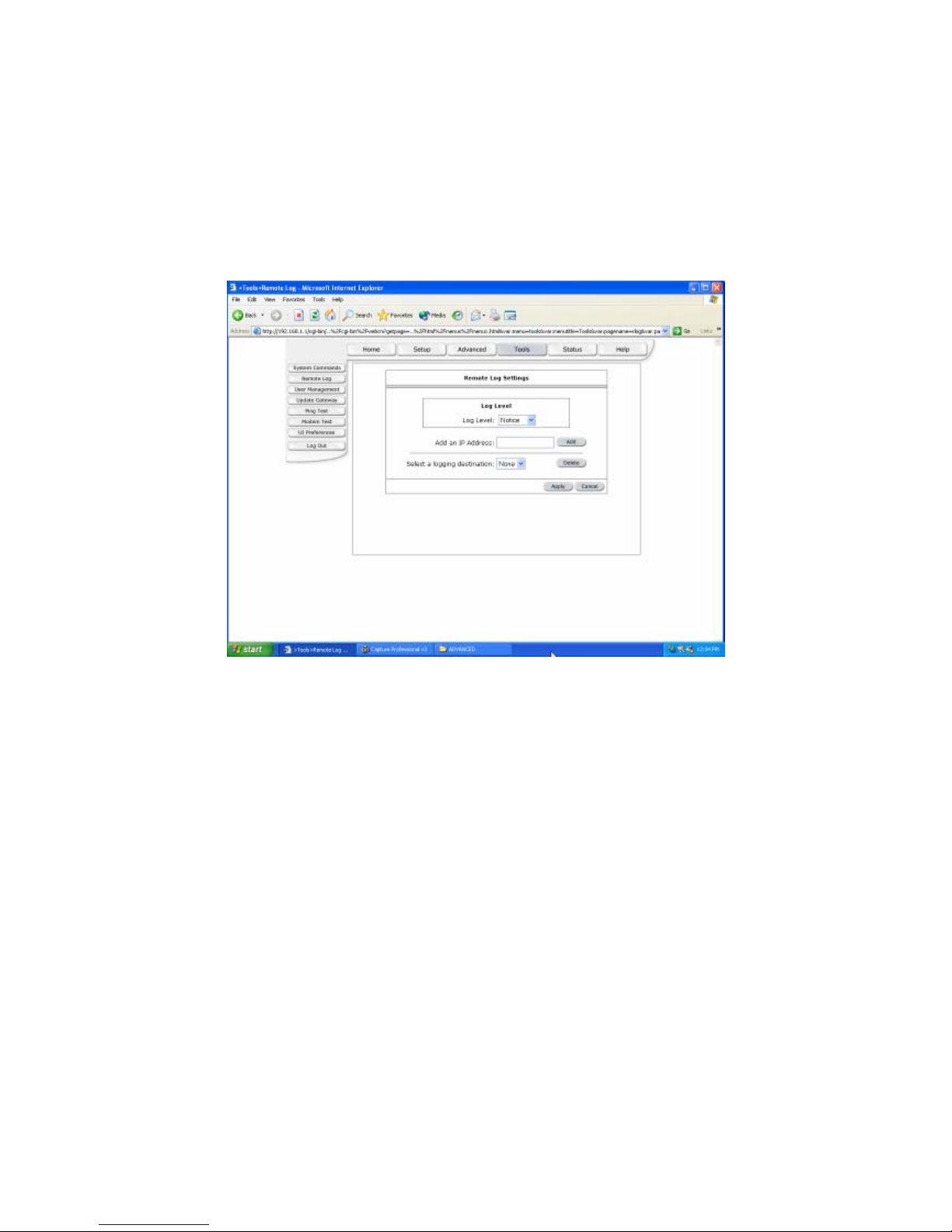
Remote Log
The Router Table page displays routing table and allows the user to manually enter the
routing entry. The routing table will display the routing status of Destination, Netmask,
Gateway and Interface. The interface br0 means the USB interface; Io0 means the
loopback interface and ppp1 means the PPP interface. The Gateway is the learned
Gateway.
Apply: Click Apply to save the changes.
41
Page 43
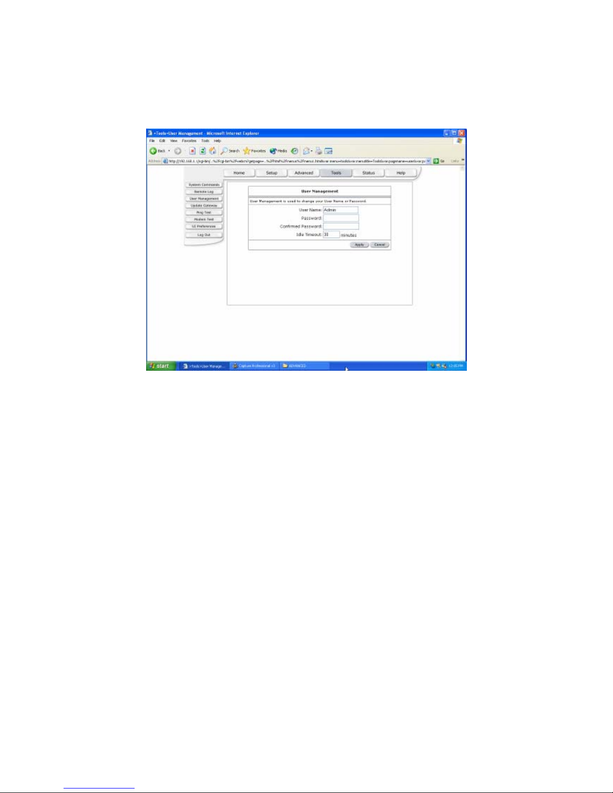
User Management
User Management is used to change your User Name or Password.
User Name: Default is ‘Admin’.
Password: Default is ‘Admin’.
Apply: Click Apply to save the changes.
42
Page 44
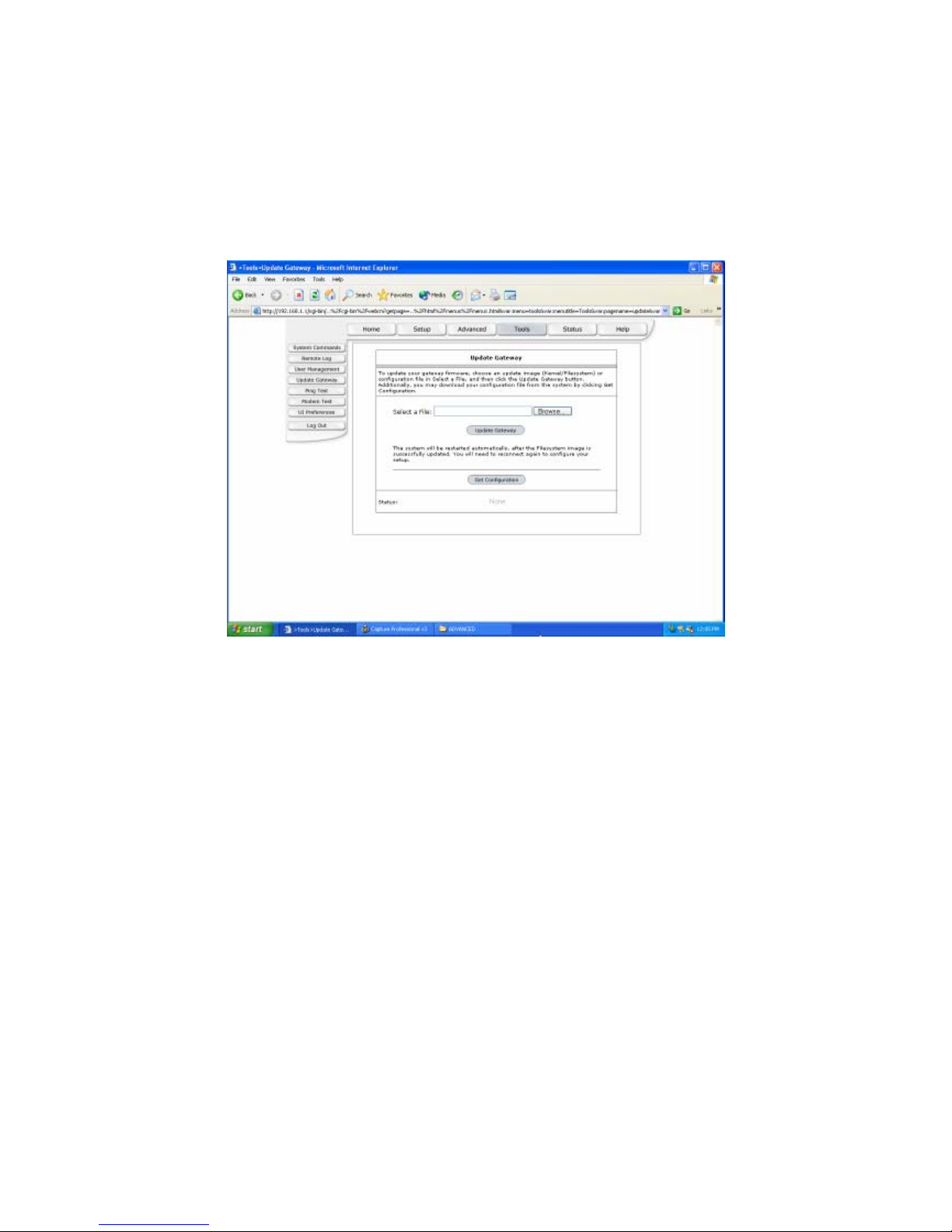
Update Gateway
To update your gateway firmware, choose an update image (Kernel/Filesystem) or
configuration file In Select a File, and then click the Update Gateway button.
Additionally, you may download your configuration file from the system by clicking Get
Configuration.
43
Page 45
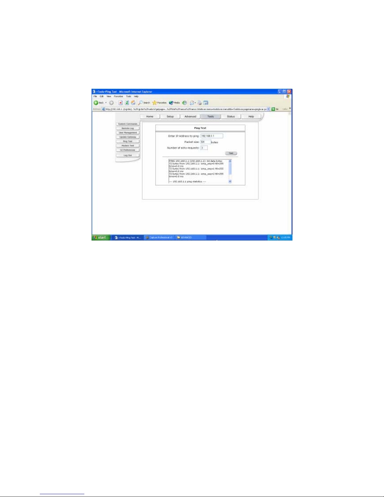
Ping Test
Packet INternet Groper is protocol that sends out ICMP echo requests to test whether or
not a remote host is reachable.
44
Page 46
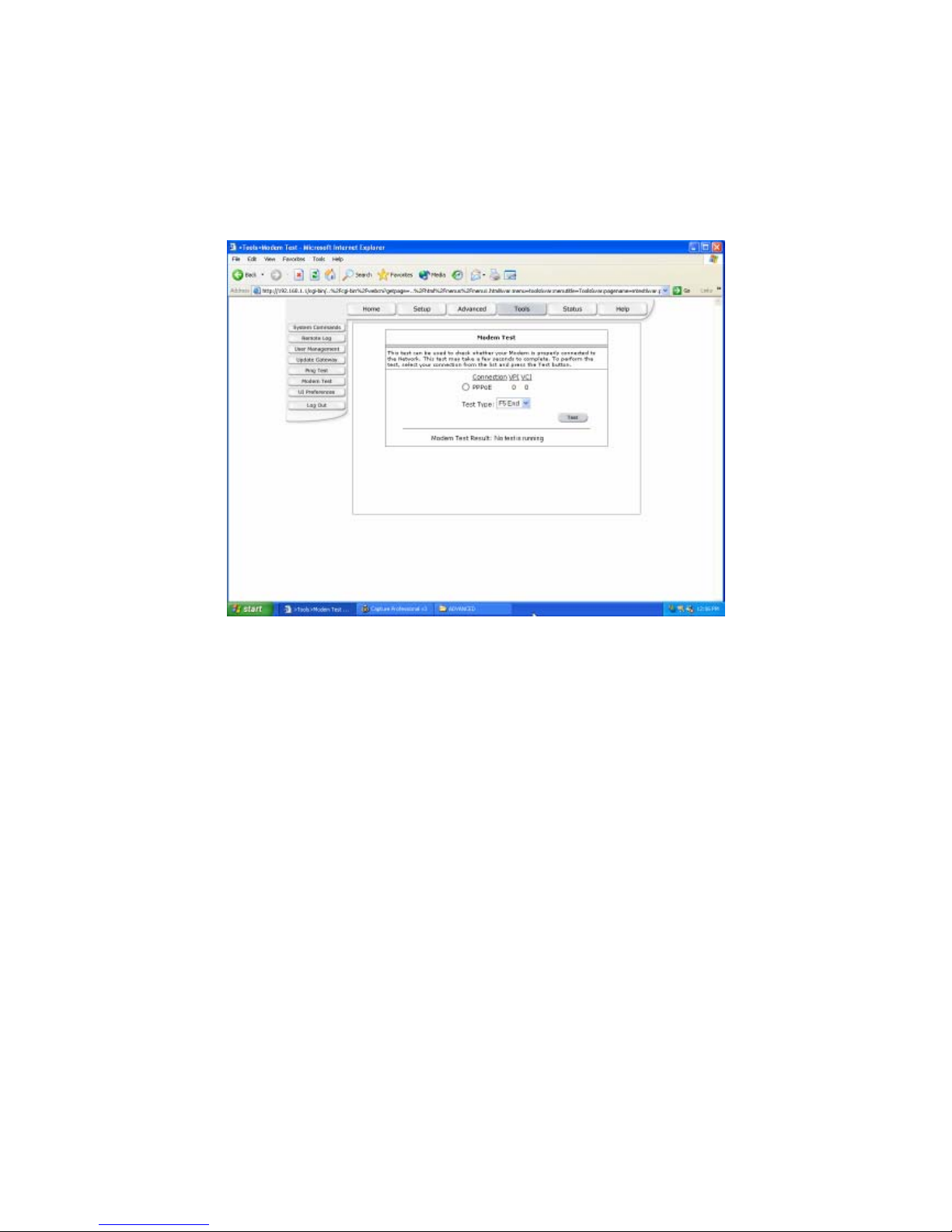
Modem Test
This test can be used to check whether your Modem is properly connected to the Network.
This test may take a few seconds to complete. To perform the test, select your connection
from the list and press the Test button.
45
Page 47
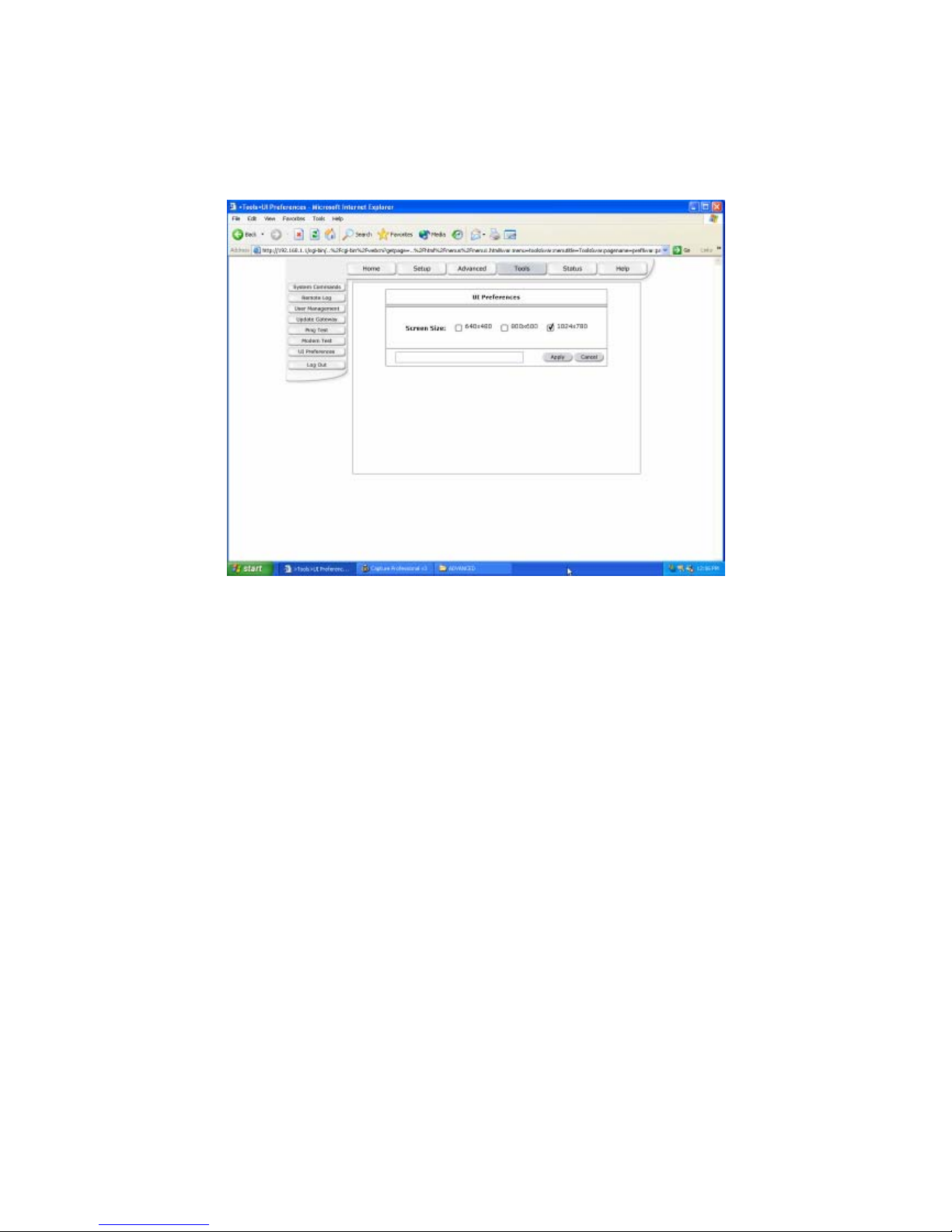
UI Preferences
The UI preferences page allows user to set screen size.
Apply: Click Apply to save the changes.
46
Page 48
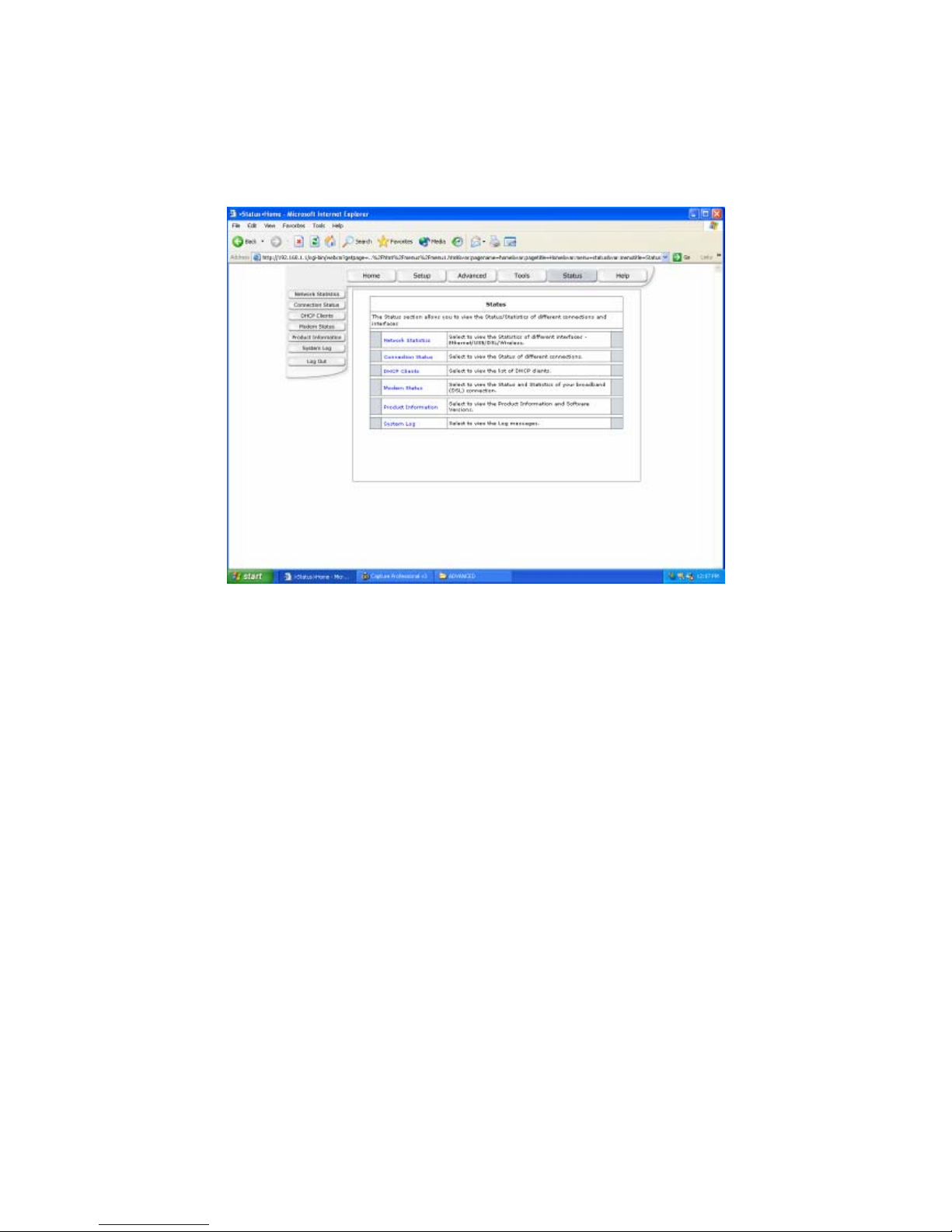
(4) Status
The Status section allows you to view the Status/Statistics of different connections and
interfaces.
47
Page 49

Network Statistics
The Ethernet Network Statistics page shows the statistics for the Ethernet connection.
The USB Network Statistics page shows the statistics for the USB connection.
The DSL Network Statistics page shows the statistics for the DSL connection.
48
Page 50
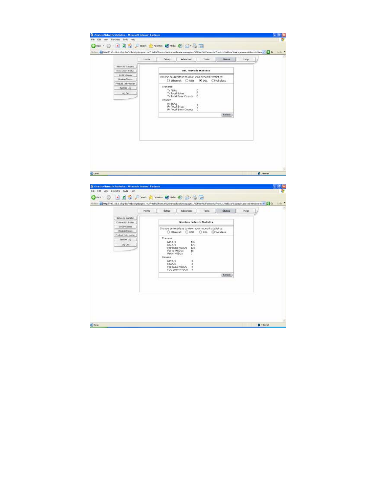
The Wireless Network Statistics page shows the statistics for the Wireless connection.
49
Page 51
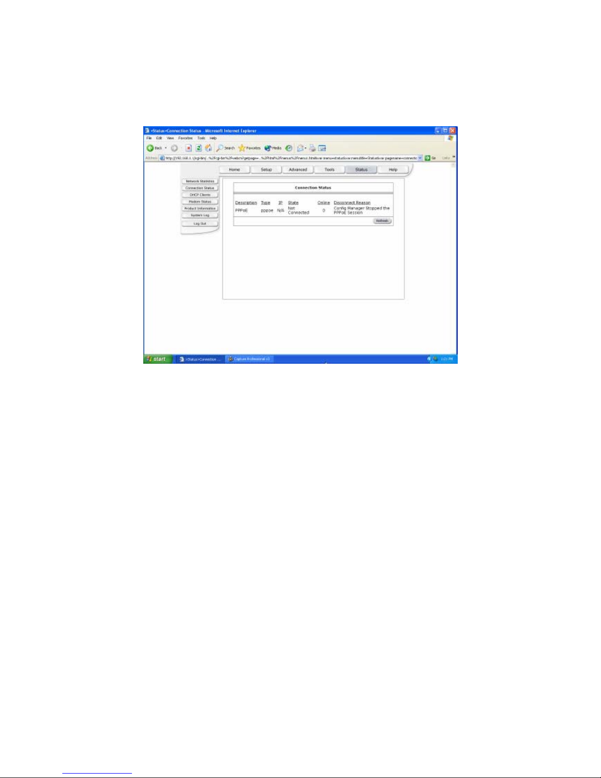
Connection Status
The Connection Status page shows the status of PPP for each PPP interface.
50
Page 52

DHCP Clients
The DHCP Clients page shows the MAC Address, IP Address, Host Name and Lease
Time.
51
Page 53
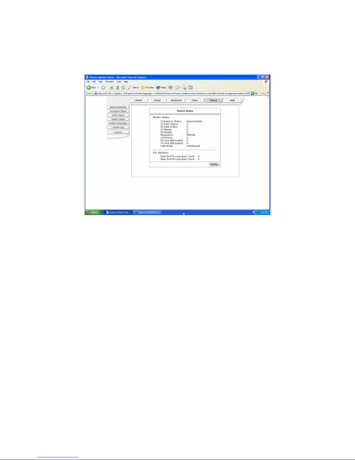
Modem Status
The Modem Status page shows the modem status and DSL statistics.
52
Page 54
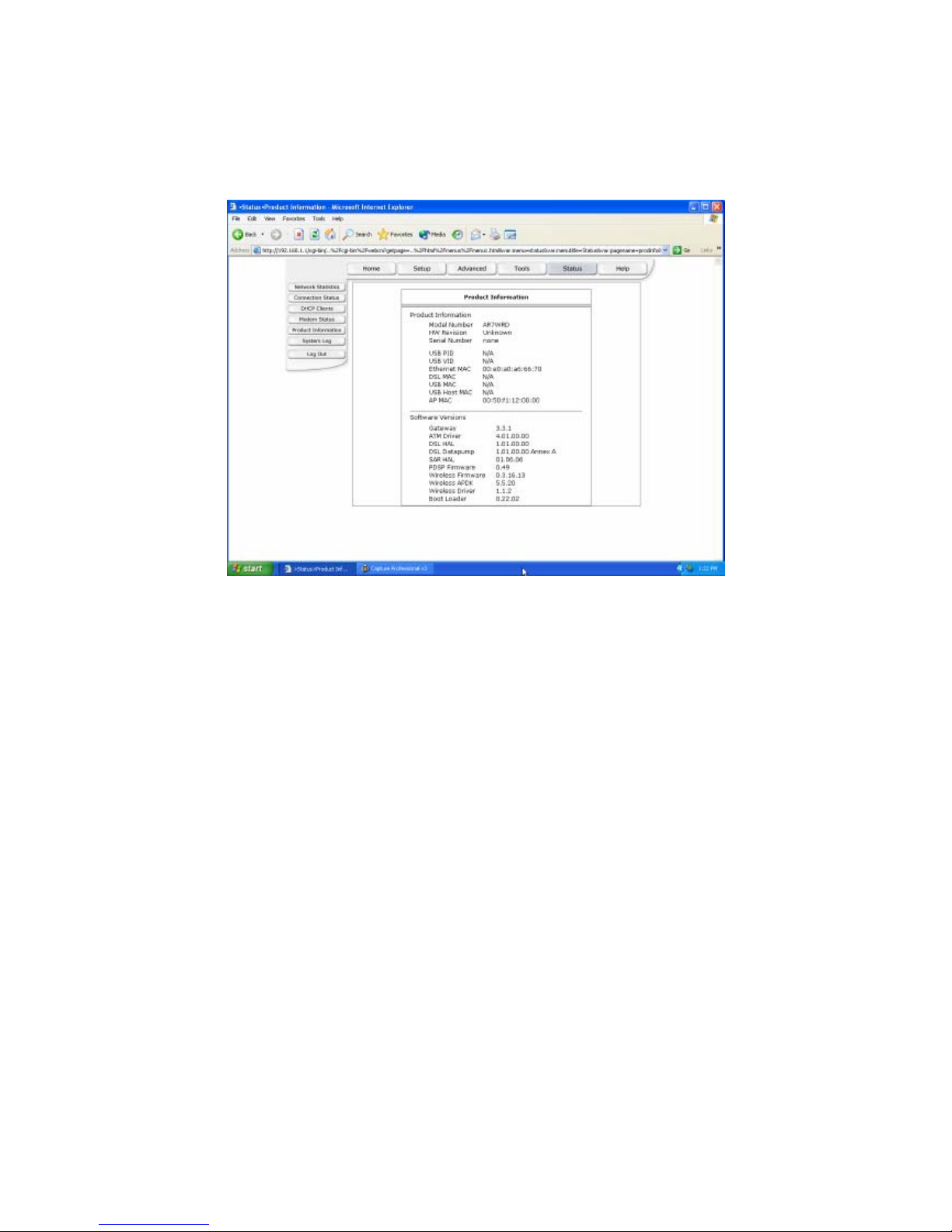
Product Information
The Product Information page shows the product information and software versions.
53
Page 55
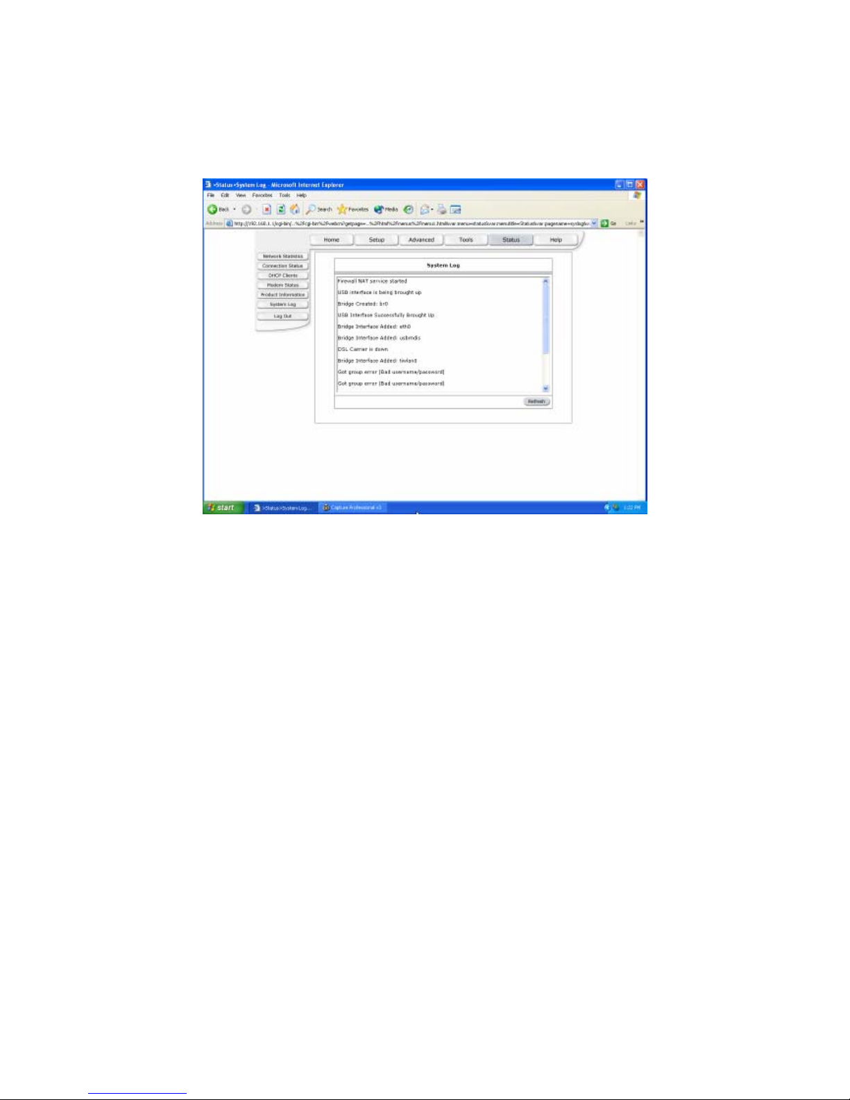
System Log
The System Log page shows the events triggered by the system.
54
Page 56
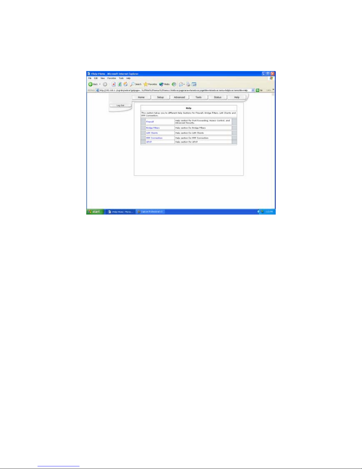
(5) Help
At this window you can access the help screens for the topic listed.
55
Page 57

Firewall
Help section for Port Forwarding, Access Control, and Advanced Security.
56
Page 58

Bridge Filters
Help section for Bridge Filters.
57
Page 59
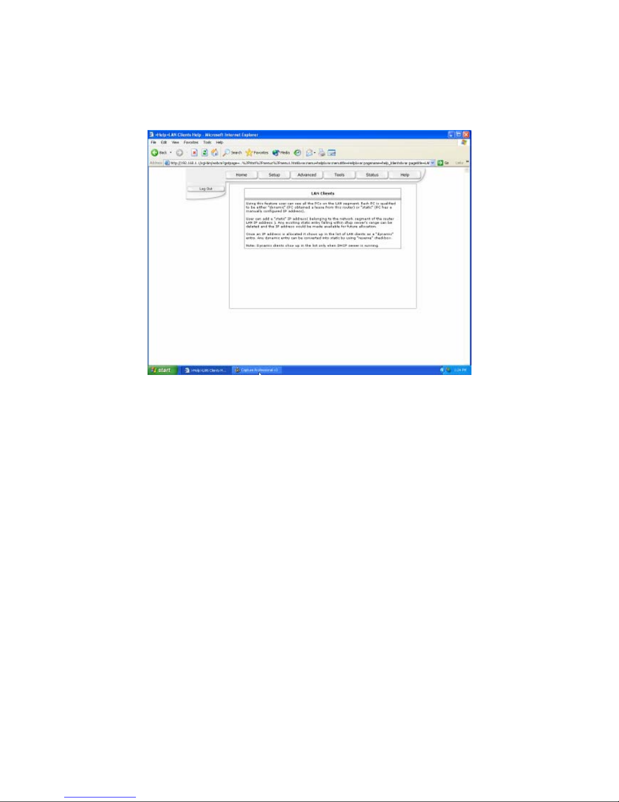
LAN Clients
Help section for LAN Clients.
58
Page 60
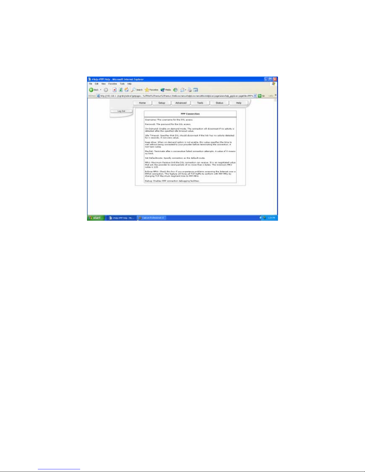
PPP Connection
Help section for PPP Connection.
59
Page 61
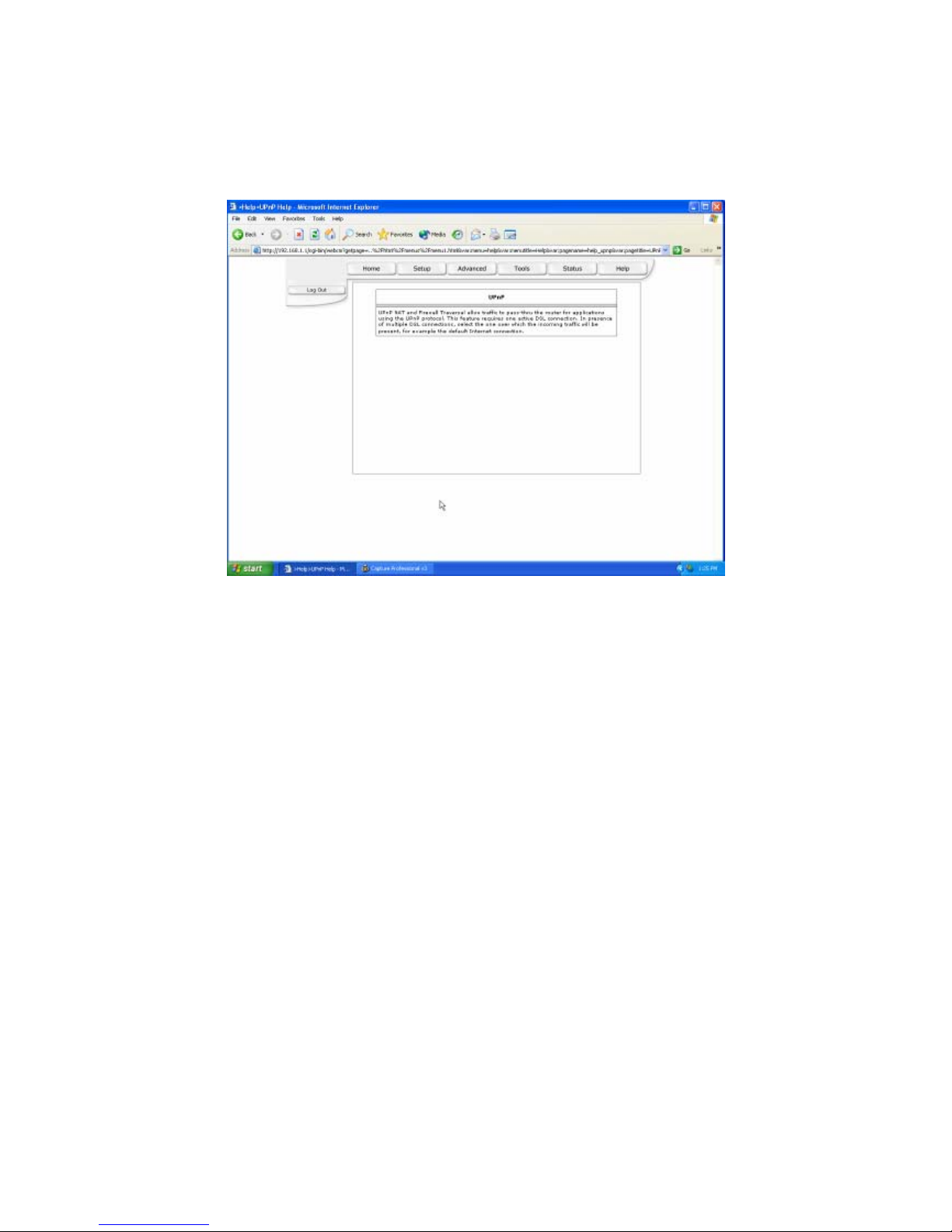
UPnP
Help section for UPnP.
60
 Loading...