

Page 1

Power over Ethernet
Single Port Injector
Installation and User’s Guide
Page 2

Notice to User
LAN Power Systems reserves the right to make changes in specifications
and other information contained in this document and it’s web site without
prior notice. The reader should in all cases consult LAN Power Systems to
determine whether any such changes have been made.
The hardware described in this document is subject to change without
notice due to market conditions or user requirements.
IN NO EVENT SHALL LPS BE LIABLE FOR ANY INCIDENTAL, INDIRECT,
SPECIAL, OR CONSEQUENTIAL DAMAGES WHATSOEVER
(INCLUDING BUT NOT LIMITED TO LOST PROFITS) ARISING OUT OF
OR RELATED TO THIS DOCUMENT, WEB SITE, OR THE INFORMATION
CONTAINED IN THEM, EVEN IF LPS HAS BEEN ADVISED OF, KNEW
OF, OR SHOULD HAVE KNOWN OF, THE POSSIBLITY OF SUCH
DAMAGES. TOTAL EXTENT OF PRODUCT WARRANTY IS
REPLACEMENT OF ANY PRODUCT DEEMED TO BE DEFECTIVE
WITHIN WARRANTY PERIOD.
LPS and any logos associated therewith, are trademarks or registered
trademarks of LPS and Trend Datacom USA, Inc. in the United States
and other Countries.
All other product names mentioned in this manual may be trademarks or
registered trademarks of their respective companies and are mentioned
here merely for clarification purposes regarding the installation and use
of LAN Power Systems products.
© 2007 LAN Power Systems and Trend Datacom USA, Inc. All rights reserved.
Revised - June 2009
I
Page 3

Two Year Limited Warranty
LPS warrants to the original consumer or purchaser that each of its products,
and all components thereof, will be free from defects in material and/or
workmanship for a period of 2 years from the original purchase date. Any
warranty hereunder is extended only to the original consumer or purchaser
and is not assignable.
LPS makes no express or implied warranties including, but not limited to,
any implied warranty of merchantability or fitness for a particular purpose,
except as expressly set forth in this warranty. In no event shall LPS be
liable for incidental or consequential damages, costs, or expenses arising
out of or in connection with the performance of the product delivered
hereunder. LPS will in no case cover damages arising out of the product
being used in a negligent fashion or manner.
NOTE: LPS reserves the right to change specifications without notice.
Please contact LPS to confirm current specifications or to inquire about
any LPS claims arising from product defects. Written inquiries maybe
addressed to
whether its products will be repaired or replaced during the warranty period.
[email protected]. LPS reserves the right to determine
II
Page 4

Table of Contents
Using This Guide
Purpose of Guide ....................................................................IV
Who Should Use this Guide ...................................................IV
If You need Help ...................................................................... V
1. Introduction
Functions and Features........................................................ 1-1
LED indicators and functions .............................................. 1-2
2. Installation and Connection
Verifying Contents of Package............................................. 2-1
Technical Considerations ..................................................... 2-2
Powering Up the Injector ...................................................... 2-3
Typical Installation of PoE Injector ...................................... 2-4
3. Troubleshooting
Checklist ................................................................................ 3-1
4. Hardware Specifications
Regulatory Compliance Standards...................................... 4-1
Safety Approvals ................................................................... 4-1
Physical / Environmental Specifications............................. 4-2
Electrical Specifications and Properties ............................. 4-3
III
Page 5

Using This Guide
Purpose of Guide
This document provides information and procedures for the
product installation and operation of the LP2521 Single Port
Power over Ethernet Injector.
Who Should Use this Guide
This document is intended for technical personnel responsible
for installing and operating Power over Ethernet products in a
Local Area Network (LAN) environment.
To use this document effectively, you should have a working
knowledge of Local Area Networking (LAN) concepts and
hardware installation. In addition, you should be familiar with the
following:
Connection of Patch Cables with RJ45 connectors
LAN addressing map for your particular Network
Mounting of Network hardware in a 19” equipment rack
Local practices for power cord connections
IV
Page 6

If You need Help
For additional support related to the contents of this document, preinstallation of product or post installation support, please contact LPS
using one of the following methods:
Phone 1-510-275-4572
Fax 1-510-661-0855
Email [email protected]
Web Address www.lan-power.com
Mail LAN Power Systems
47835 Westinghouse Drive
Fremont, CA 94539
Before contacting LPS for technical support, please have the
following information ready:
Your LPS product model number and unit serial number
A description of the failure or symptons of problem
A description of any action(s) already taken to resolve the
problem (e.g., changing ports , rebooting the unit, etc...)
The type of End device being powered including Manufacturer
name and part number
Powering requirements of the End device
A description of your Network environment (layout, Ethernet
switch description, cable type, etc...)
The unit history (i.e., have you returned the unit before, is
this a recurring problem, etc...)
V
Page 7

Introduction
Functions and Features
The LPS Model LP2521 Single Port Power over Ethernet (PoE)
Injector supports powering applications in which AC Power is
difficult or costly to access, such as VoIP Phones, Wireless LAN
Access Points, Internet Security Cameras, or other Network
devices.
The Single Port PoE Injector acts as a “patch panel” and adds
~48 VDC to unused (non-data) wires in a standard Category 5,
5e, or 6 Ethernet cable. The LP2521 delivers both data and
power over a single standard Ethernet cable to an End device
designed to receive both Data and Power through its RJ45
connector.
Key features of the Single Port PoE Injector include:
1
Exceeds IEEE 802.3af Power over Ethernet Standards
Supports Data links at 10Mbs, 100Mbs or 1000Mbs
Output Wattage is up to 28W continuously
Non-Conducting plastic case
Over voltage current and Short circuit protected
1-1
Page 8

Functions and Features continued
Removable Power Cord w/IEC-320-C7 connector
Data and Power carried on same Ethernet cable
Ships with wall mounting bracket - use if needed
LED indicators and functions
The LP2521 PoE Injector has two LED’s which assist with
understanding unit operation.
LED #1 - Unit Power - The LED glows GREEN if input
power is being received properly from AC outlet - This
indicates the unit is capable of forwarding power to the
End device.
LED #2 - Connection to End device and Power
forwarding - The LED glows GREEN if detection is
achieved with the End device and power is being
forwarded out over the Ethernet cable.
See Section 3, Troubleshooting, if Ethernet and Power cords are
properly attached and if both LED’s are not on in a steady
GREEN condition.
1-2
Page 9
Installation and Connection
Electrical Hazard: Only qualified personnel should install this
unit. Read instructions before attempting to install this unit.
Verifying Contents of Package
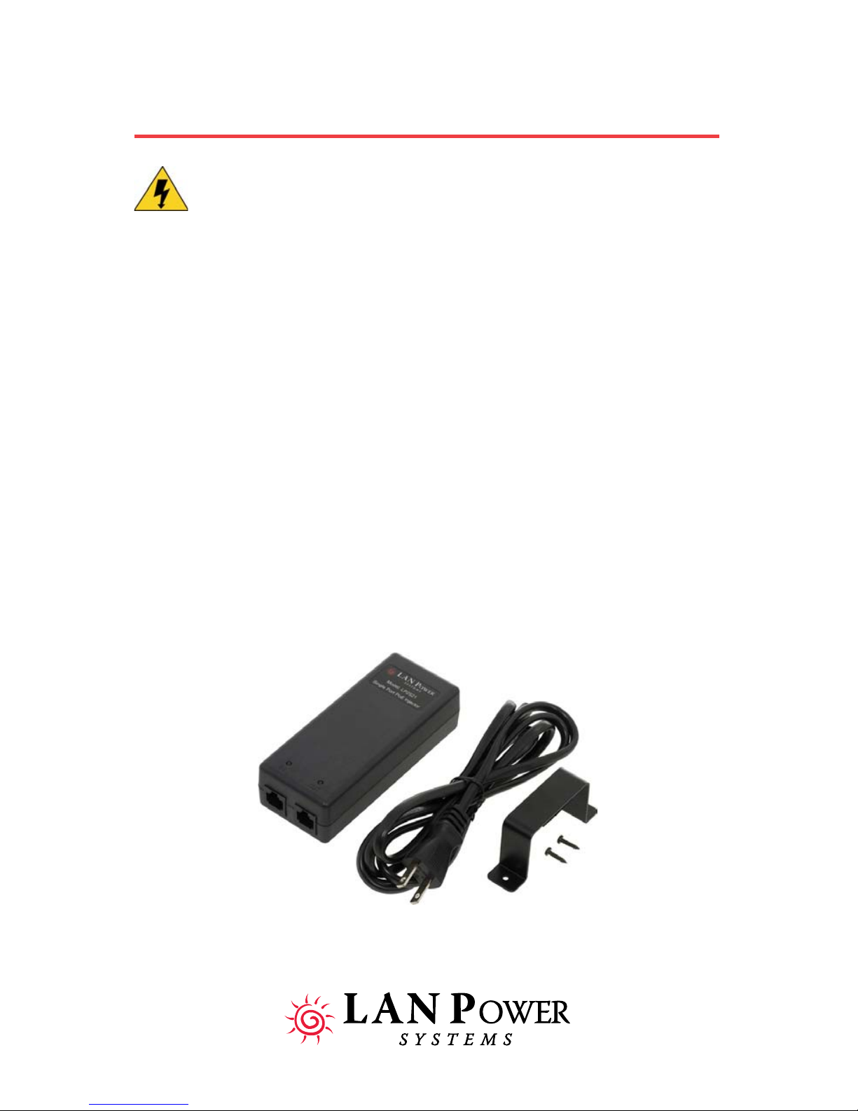
Unpack the PoE Injector and verify that you have all of the
following items:
Single Port Power over Ethernet Injector
Power Cord
2
Wall Mounting bracket and screws
2-1
Page 10

Technical Considerations
Before you mount the PoE Injector to a fixed location, consider all of the
following:
Determine optimal placement, check patch cord routing
and AC outlet location.
Collect and document Network information as required.
Ensure the cable length from the Ethernet Network
Switch to the Powered End device does not exceed 100
meters total length.
Note: The PoE Injector is not a repeater and does not amplify
the Ethernet data signal. The Injector must be used in
conjunction with an Ethernet Switch.
Caution: Observe the following considerations when installing
the Single Port PoE Injector.
Connect the Injector to a grounding type AC outlet (100-
240 VAC), using the standard power cord supplied.
Allow for easy access to disconnect the unit from the AC
outlet or UPS, if necessary.
Do not cover the unit or block airflow with any other
objects. Keep the unit away from excessive heat,
humidity, vibration and dust.
Installation must at all times conform to local regulations
There are no user serviceable parts inside the Injector.
If support is needed, refer to “If You need Help” on page V.
SELV - Safety Extra Low Voltage (Connect only to PoE
Networks without routing to the ourside plant)
2-2
Page 11

Powering Up the Injector
Plug one end of the power cord into the Injector and the other end into a
grounded AC power source. Units are typically connected to a power
strip or other power outlet that may be cycled on and off. An
uniterruptible power supply (UPS) may be used. This assures
uninterrupted power to the End device should there be a loss of building
power.
Safety Instructions: The means of connection to the mains supply is the
detachable power cord of the equipment. The equipment disconnect
device is the appliance inlet. The AC socket outlet shall be installed near
the equipment and shall be easily accessible.
Next, attach a LAN data cable patch cord of minimum Cat5 cable grade
from the Ethernet Switch port to the RJ45 connector on PoE Injector
marked “IN”. Then attach a second patch cable from the “OUT” RJ45
connector on the PoE Injector to the structured wiring connection leading
to the device to be powered. Turn on power source. The “IN” LED on
the Injector will glow “GREEN”. If End device to be powered is already
installed on Network, the “OUT” LED will glow “GREEN”. The PoE
Injector is now correctly installed and operating.
2-3
Page 12
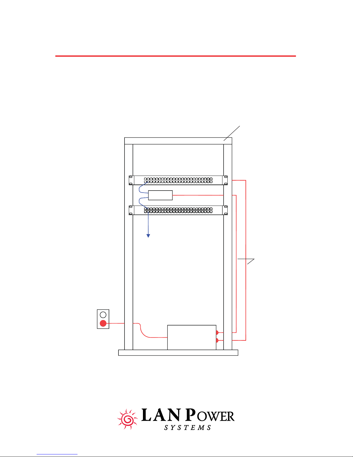
Typical Installation of PoE Injector
Datacom Wiring
Closet
Ethernet Switch
LP2521
Patch Panel
19” Equipment Rack
Grounded AC
Outlet
Power
Cords
UPS System
2-4
Page 13
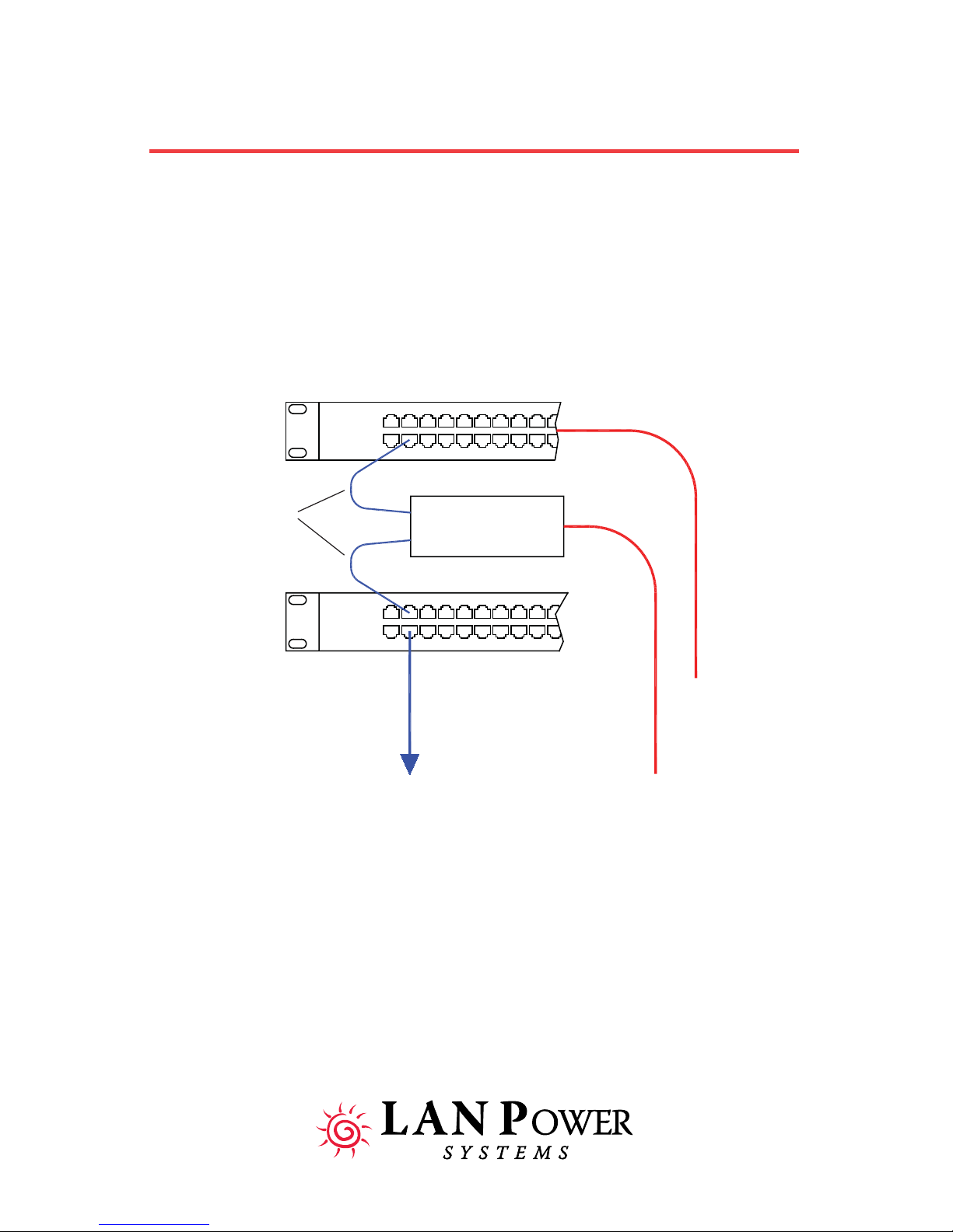
Typical Installation of PoE Injector (continued)
Ethernet Switch
IN
Category5(min)
Patch Cords
OUT
PoE Injector
LP2521
Structured Cabling
Connection to
End-Device
IP-Phone, Wireless AP,
IP Security Camera, etc...
Patch Panel
Power Cords
to UPS or
AC Outlet
2-5
Page 14

Troubleshooting
Refer to the Troubleshooting Checklist for a list of problems and recommended actions to resolve the problem. If additional support is needed,
refer to “If You need Help” on page V.
Following the Troubleshooting procedures below will usually
resolve a Power over Ethernet Installation problem. The LAN
Power Support Team has found that these are the most often
encountered trouble items when adding Single Port PoE Injectors
to an existing Ethernet Network.
Troubleshooting Checklist:
Problem 1:
The Single Port PoE Injector is plugged in but “Power In” LED is not lit
(Green).
Recommended Actions:
Verify the power cord is plugged in all the way into the PoE Injector.
3
Verify the AC connection is “hot” by plugging in some other device and
making sure there is actually power at the outlet. Input voltage must be
from 90-264 VAC and 50-60Hz.
If the “Power In” LED will not light with the unit plugged in, call or write
to LAN Power Systems for Tech. Support.
Problem 2:
The Single Port PoE Injector is plugged in and “Power In” LED is lit
(Green). But the “Power Out” LED is not lit and End device is not being
powered.
Recommended Actions:
Verify use of working patch cables of at least Category 5 grade. Verify
they are Straight-through patch cables and NOT Cross-over cables.
Verify connection of good patch cable from Ethernet Switch port to “IN”
RJ-45 connection on PoE Injector. Verify connection of good patch
cable from “OUT” RJ-45 connection on PoE Injector to Patching panel
connection linking to End device to be powered.
-continued on next page-
3-1
Page 15

Troubleshooting Checklist (continued)
IF “OUT” LED on PoE Injector is still not lit (Green), continue with these
steps.
Bring End device to be powered into the same room (wiring closet)
where you are working and connect it directly to the patch cable already
attached to “OUT” RJ-45 Connector on PoE Injector. If “OUT” LED lights
up (Green) and power light is now lit on the End device, the PoE Injector
is working fine.
The problem must be then in the Cable link going out to where the End
device was first located. PoE requires the use of all 8 wires in the LAN
Data cable. It is possible not all 8 wires are available or terminated in
that particular link in the Structured Cabling System. Try using a
different Cable link to a nearby or similar location and see if the PoE
Injector can now power the End device remotely using that Cable link.
OR the patch cord from the end of the Cable link to the End device
could be bad, try replacing with another known good patch cable.
If You have the End device to be powered connected locally to the PoE
Injector, with known good patch cords, and the “OUT” LED on the PoE
Injector does not light up and power the End device, check the
following. Verify that the Make and Model of End device you are trying
to power is actually made from the Manufacturer to accept PoE. If so,
verify that the style of PoE (protocol) that the End device wants to
receive is the same style that the PoE Injector is putting out.
Example: the LP2521 is putting out IEEE 802.3af PoE. The End device
must be built ready to accept IEEE 802.3af PoE. Some products in the
marketplace are not, some accept other PoE styles like legacy Cisco
CDP style PoE (see Support section, Compatible Products listing at
www.lan-power.com). Others need 24v or 12v or 5 volts input. LAN
Power Systems has Voltage Adapters and Power Pin and Data cables
available for these low voltage PoE applications (see Products section
of LAN Power Website at www.lan-power.com).
3-2
Page 16

Troubleshooting Checklist (continued)
Problem 3:
PoE Injector has Input and Output LEDs both lit (Green), End device is
being powered, but End device has no Data link from the Ethernet
Switch (is not responding to the Network).
Recommended Actions:
Verify Ethernet Switch port is good, turned on, and not being blocked for
traffic forwarding by either a hard set or soft set in Network
Management Software.
Check or change out patch cord from Switch port to PoE Injector,
making sure a Straight-through patch cord is being used and NOT a
Crossover cable.
Verify Cable link to End device is at least Category 5 and has a distance
of no more than 100 meters total length, including patch cables. If a
Cable testing unit is available, wring out the data link to make sure there
are no hidden breaks or damage to any of the cable’s 8 wires and that
all RJ-45 connection points along the data link are good.
Try using a different End device. If the new End device works and the
Data link works correctly, the problem is with the End device. Speak with
that Manufacturer for Technical support or return of the problem End
device.
If these actions have all been taken and you still are not getting a
functional Power and Data link to your End device, please call or write
to LAN Power Systems for additional support and troubleshooting ideas.
3-3
Page 17

Hardware Specifications
This appendix lists the LP2521 Single Port Power over Ethernet Injector
hardware and electrical specifications.
4
Regulatory Compliance Standards
This equipment meets the following electromagnetic
compatibility (EMC) requirements:
Electromagnetic
Compatibility (EMC)
Safety Approvals
The equipment meets the following safety approvals:
FCC CE
VCCI
VCCI 2001 ClassB,
47 CFR Parts 2 and 15,
EN55022, EN61000-3-2,
EN61000-3-3, EN61000-4-2,
EN61000-4-3, EN61000-4-4,
EN61000-4-5, EN61000-4-6,
EN61000-4-11
4-1
Page 18

Hardware Specifications continued
Physical Specifications
Height: 1-3/8” (34.9mm)
Width: 2-3/16” (55.5mm)
Length: 5-1/16” (128.6mm)
Unit Weight: 5.1 oz. (0.15 kg)
Package Weight: 11.5 oz. (0.33 kg)
Unit Mounting: Shelf mount or wall mount with included bracket
LED Indicators
2 for Single PoE Output port
Left hand side(IN): Power available to forward (Green)
Right hand side(OUT): Detect and power forwarding (Green)
Environmental Specifications
Operating Temperature:40° to 185° F / -40° to 85° C
Storage Temperature: 40° to 185° F / -40° to 85° C
Relative Humidity: 10% to 90% non-condensing
Operating Altitude: -1,000 to 10,000 feet above Sea level
-305 to 3,048 meters above Sea level
Ethernet Data Throughput Speeds
10 Mbs Ethernet, 100 Mbs Fast Ethernet
or 1000 Mbs Gigabit Ethernet supported
Connector Type
Non-Shielded RJ-45, meets EIA 568A and 568B
4-2
Page 19

Hardware Specifications continued
Electrical Specifications and Properties
AC Power Input
Power Cord type: Removable with IEC 320-C7 connector
on Single Port Injector end, North
American 2-Pin on outlet end
Power Supply: Single, Internal
Voltage Range: 90 - 264VAC
Voltage Rating: 100 - 240VAC
Frequency Range: 47 - 63Hz
Frequency Rating: 50 - 60Hz
Input Current: 1.0A (rms) Max.
@Voltage Range and Voltage Rating
DC Power Output
PoE Protocol: IEEE 802.3af Standard
Power on Data Pins: 4 & 5 (+), 7 & 8 (-) (unused pairs)
Output Voltage: 48VDC (+10%-0)
Max. Power on Port: 28W (exceeds PoE Standard)
Load: 0A (Min.) 0.35A (Max.)
Regulation (Line/Load): ± 4%
Efficiency: >75%
Hold-up Time: 20mS Min. @ 240VAC Input
Ripple and Noise* Vp-p*
<500Hz 0.50
500Hz-150KHz 0.15
150KHz-500KHz 0.15
500KHz-1MHz 0.10
* As per IEEE802.3af Table 33-5
Thermal Output 15 BTUs
4-3
 Loading...