

Page 1

Rev. A+
System Board User’s Manual
Carte Mère Manuel Pour Utilisateur
System-Platine Benutzerhandbuch
Manual del Usuario de Placas Base
Руководство Пользователя
935-875001-000
74800331
Page 2

Copyright
This publication contains information that is protected by copyright.
No par t of it may be reproduced in any form or by any means or
used to make any transformation/adaptation without the prior
written permission from the copyr ight holder s.
This publication is provided for informational purposes only. The
manufacturer makes no representations or warranties with respect to
the contents or use of this manual and specifically disclaims any
express or implied warranties of merchantability or fitness for any
par ticular purpose . The user will assume the entire risk of the use or
the results of the use of this document. Fur ther, the manufacturer
reser ves the right to revise this publication and make changes to its
contents at any time, without obligation to notify any person or
entity of such revisions or changes.
© 2003. All Rights Reser ved.
Trademarks
Windows® 98 SE, Windows® ME, Windows® 2000, Windows NT
4.0 and Windows® XP are registered trademarks of Microsoft
Corporation. Intel® and Pentium® 4 are registered trademarks of
Intel Corporation. Award is a registered trademark of Award
Software, Inc. Other trademarks and registered trademarks of
products appearing in this manual are the properties of their
respective holders.
Caution
To avoid damage to the system:
• Use the correct AC input voltage range
To reduce the r isk of electr ic shock:
• Unplug the power cord before removing the system chassis
cover for installation or servicing. After installation or ser vicing,
cover the system chassis before plugging the power cord.
..
.
..
®
Page 3

Battery:
• Danger of explosion if batter y incor rectly replaced.
• Replace only with the same or equivalent type recommend
the manufacturer.
• Dispose of used batteries according to the battery
manufacturer’s
Joystick or MIDI port:
• Do not use any joystick or MIDI device that requires more than
10A current at 5V DC. There is a risk of fire for devices that
exceed this limit.
instructions.
FCC and DOC Statement on Class B
This equipment has been tested and found to comply with the limits
for a Class B digital device, pursuant to Part 15 of the FCC r ules.
These limits are designed to provide reasonable protection against
harmful interference when the equipment is operated in a residential
installation. This equipment generates, uses and can radiate radio
frequency energy and, if not installed and used in accordance with
the instruction manual, may cause harmful interference to radio
communications. However, there is no guarantee that interference
will not occur in a par ticular installation. If this equipment does cause
harmful interference to radio or television reception, which can be
determined by turning the equipment off and on, the user is
encouraged to tr y to cor rect the interference by one or more of the
following measures:
by
• Reorient or relocate the receiving antenna.
• Increase the separation between the equipment and the receiver.
• Connect the equipment into an outlet on a circuit different from
that to which the receiver is connected.
• Consult the dealer or an experienced radio TV technician for
help.
Notice:
1. The changes or modifications not expressly approved by the
par ty responsible for compliance could void the user's authority
to operate the equipment.
2. Shielded interface cables must be used in order to comply with
the emission limits.
Page 4

1
Quick Setup Guide
Important Configuration and Driver Installation Rules
HighPoint RAID IDE Controller
Guide
Quick Setup
By default, the HighPoint RAID IDE controller is enabled. If you are
not using this function, make sure to set the “RAID Device Control”
field in the Genie BIOS Setting submenu of the Award BIOS to
Disabled.
Make sure to follow the rule mentioned above. Doing it otherwise
will slow down the boot up time and affect the performance of the
system.
Driver Installation Rules
Please follow the installation sequence below.
1. Install the “Audio Drivers”.
2. Install the “Intel Chipset Software Installation Utility”.
3. Install the other driver s and utilities.
Make sure to follow this sequence. Doing it otherwise will slow down
the boot up time and affect the performance of the system.
The user’s manual in the provided CD contains detailed information about the system
board. If, in some cases, some information doesn’t match those shown in this manual, this
manual should always be regarded as the most updated version.
Le manuel d’utilisateur dans le CD muni contient renseignement détaillé au sujet de carte
de système. Si, en quelque cas, quelque renseignement n’appareille de ce que dit dans ce
manuel, ce manuel doit toujours être considéré comme la plus nouvelle version.
Das Benutzerhandbuch in der angebotenen CD enthält detaillierte Informationen über die
Hauptplatine. Wenn in manchen Fällen manche Informationen nicht denjenigen Informationen
dargestellt in diesem Handbuch entsprechen, soll dieses Handbuch als die meist
aktualisierte Ausgabe gelten.
El uso explicativo contene información detalle sobre la sistema board en el CD preparativo.
Si en algún caso, la información no es igual con el uso explicativo, necesita ver el uso
explicativo, esque es más nuevo.
В руководстве пользователя на предоставляемом CD диске содержится
подробная информация о материнской плате. Иногда напечатанное
руководство может не совпадать руководством на CD, так как последнее
наиболее часто обновляется и является самым свежим.
4
Page 5

Table of Contents
Quick Setup Guide
1
Chapter 1
Quick Setup Guide.............................................
Chapter 2
English......................................................................
Chapter 3
Français....................................................................
Chapter 4
Deutsch...............................................................................
Chapter 5
Español............................................................................
Chapter 6
Русский......................................................................
18
24
30
36
42
6
Guide
Quick Setup
5
Page 6
1
Quick Setup Guide
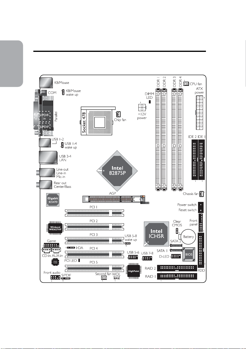
Chapter 1 - Quick Setup Guide
1.1 System Board Layout
Guide
Quick Setup
6
Page 7
1.2 Jumpers
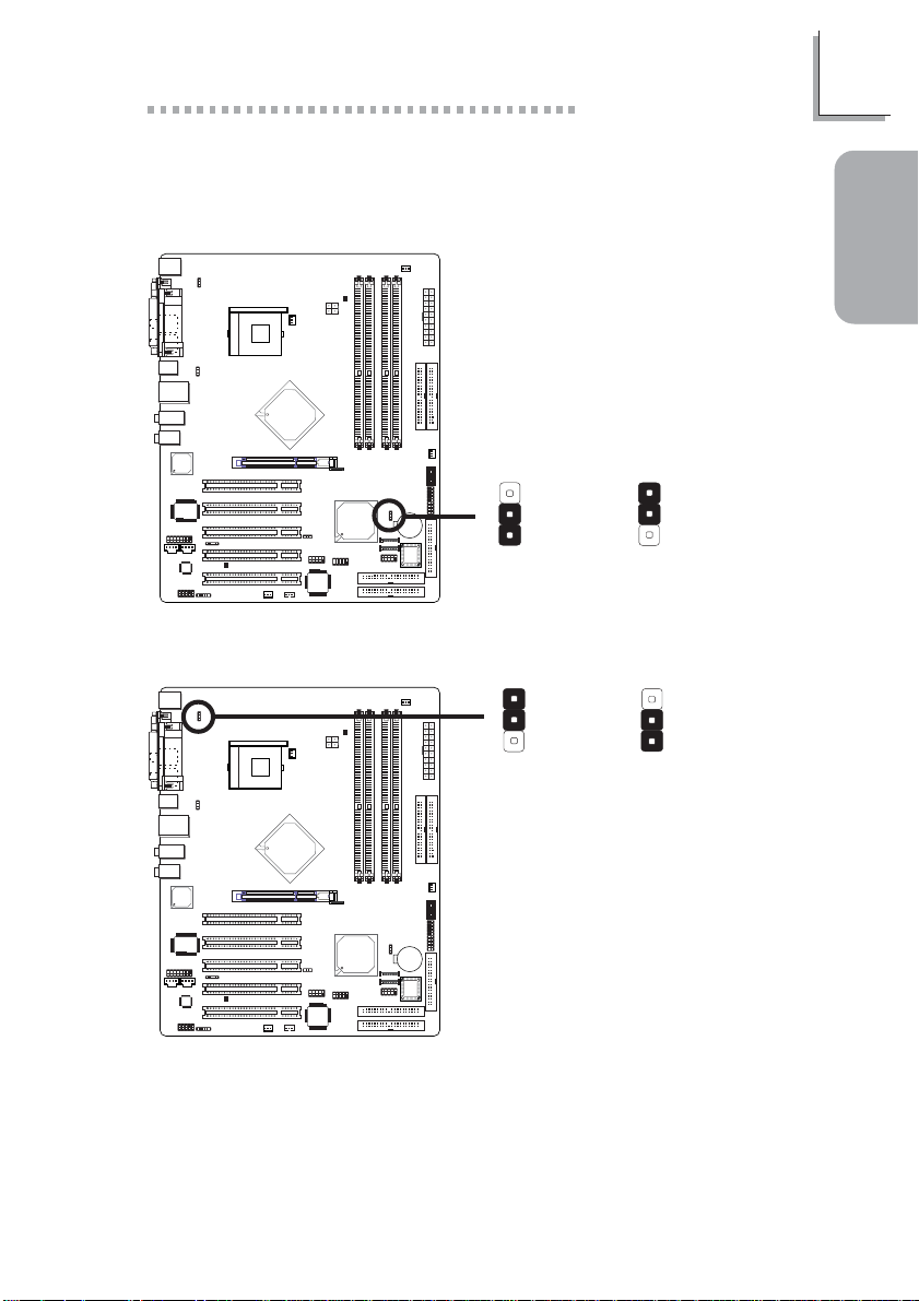
1.2.1 Clear CMOS Data - JP5
Quick Setup Guide
1
Guide
Quick Setup
3
2
1
2-3 On:
!
(default)
3
2
1
JP5
1-2 On: Normal
Clear CMOS Data
1.2.2 Wake-On-Keyboard/Wake-On-Mouse - JP1
!
(default)
1
2
3
2-3 On: Enabled
JP1
1-2 On: Disabled
The 5VSB power source of your power supply must support ≥720mA.
1
2
3
7
Page 8
1
Quick Setup Guide
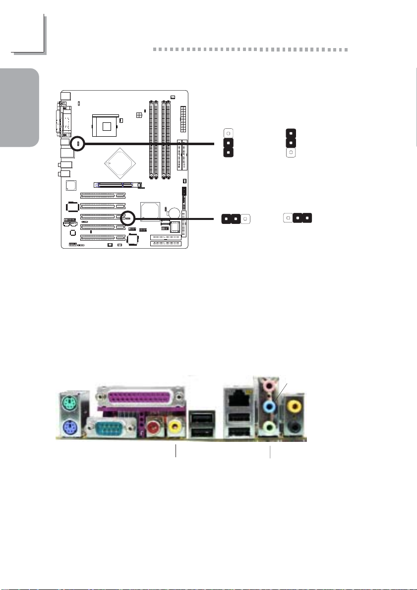
1.2.3 Wake-On-USB Keyboard - JP2 and JP6
Guide
Quick Setup
USB 1-4
(JP2)
!
1-2 On: Disabled
(default)
3
2
1
3
2
1
2-3 On: Enabled
USB 5-8
(JP6)
312
312
!
1-2 On: Disabled
(default)
If you are using the Wake-On-USB Keyboard function for 2 USB por ts,
the 5VSB power source of your power supply must suppor t ≥1.5A.
If you are using the Wake-On-USB Keyboard function for 3 or more
USB ports, the 5VSB power source of your power supply must support ≥2A.
2-3 On: Enabled
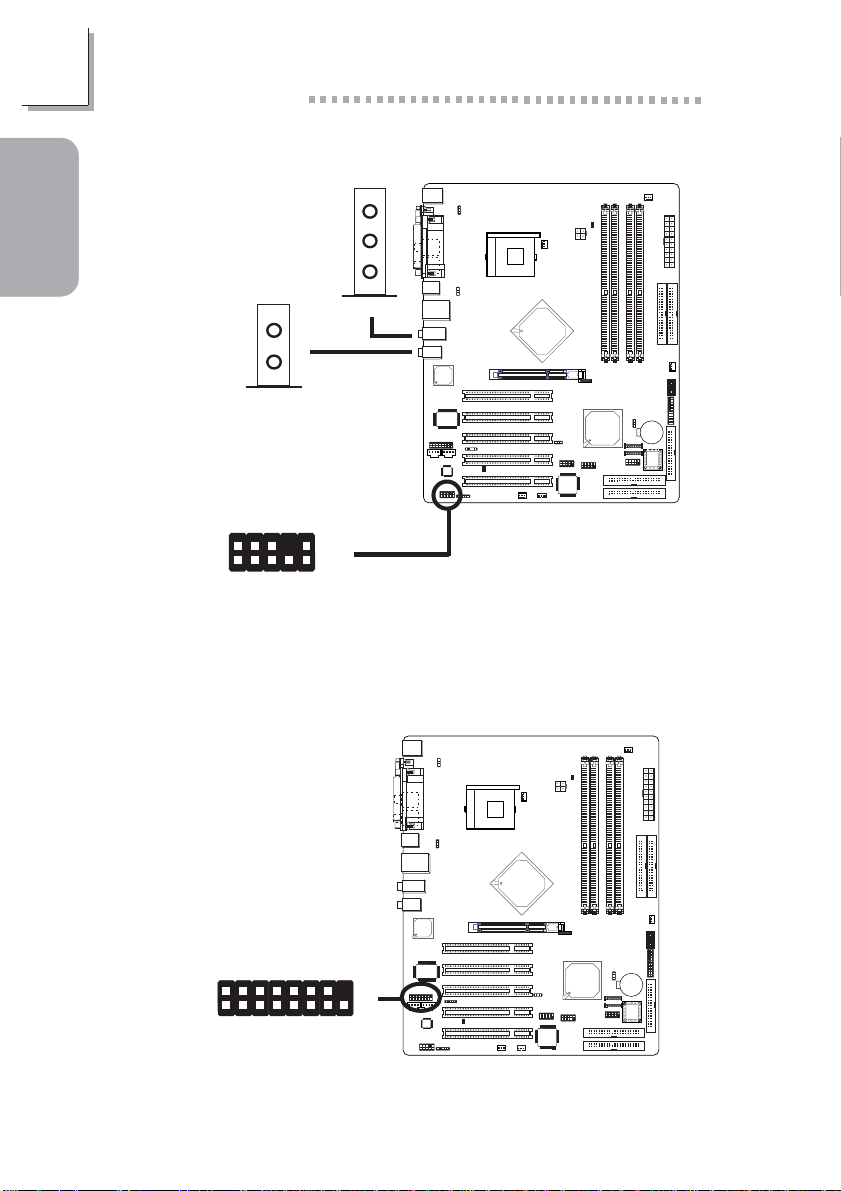
1.3 Rear Panel I/O Ports
RJ45
PS/2
Mouse
PS/2
K/B
Parallel
COM S/PDIF-in
S/PDIF-out
USB 2
USB 1 USB 3-4
LAN
Mic-in
Line-in
Center/Bass
Rear out
Line-out
8
Page 9
1.4 I/O Connectors
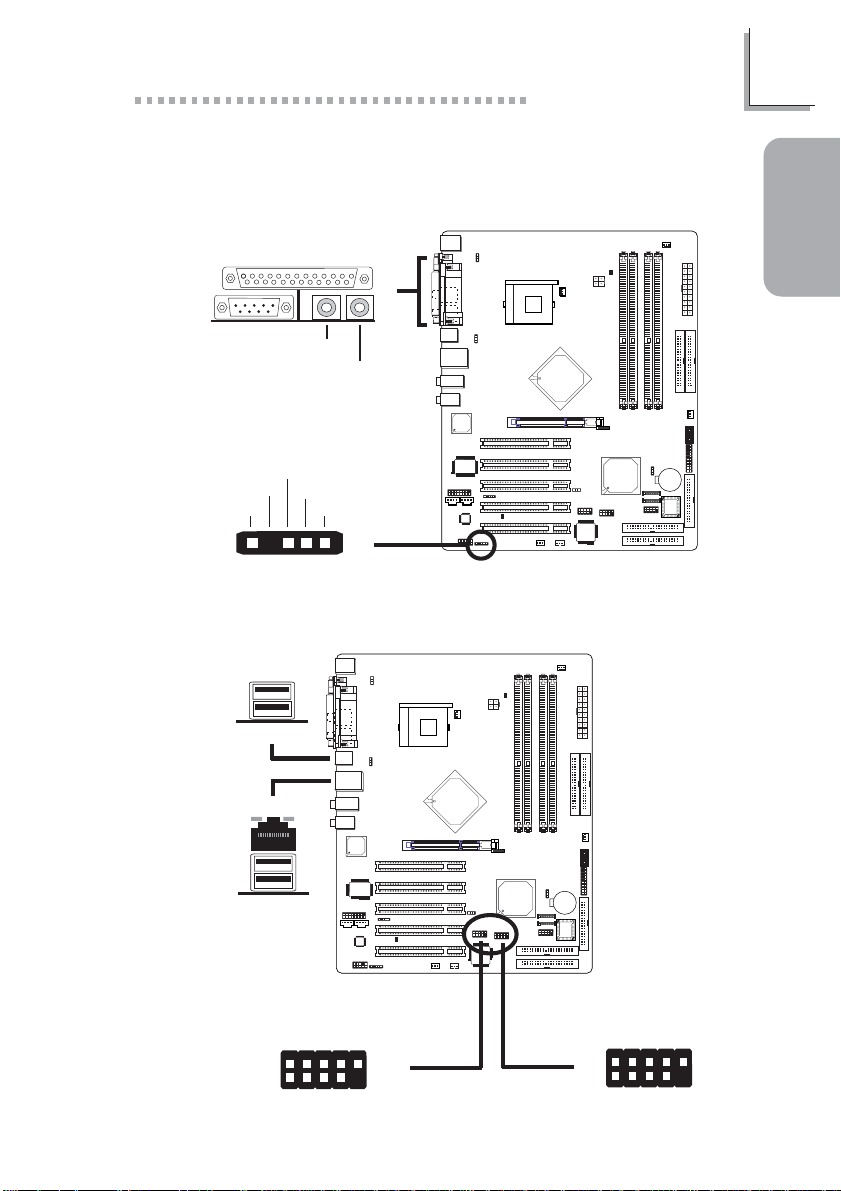
1.4.1 S/PDIF-in/out Jacks
Quick Setup Guide
1
Guide
"
S/PDIF-in
S/PDIF-out
RCA Jacks
SPDIF out
Key
GND
VCC
15
For optical S/PDIF cable connection.
SPDIF in
J4
"
1.4.2 Universal Serial Bus Ports
USB 2
USB 1
"
"
Quick Setup
USB 4
USB 3
N. C.
Ground
+Data
VCC
-Data
2
1
VCC
-Data
+Data
Ground
10
Key
USB 5-6
"
9
USB 7-8
"
-Data
-Data
+Data
10
9
Key
Ground
9
2
1
VCC
N. C.
Ground
+Data
VCC
Page 10
1
Quick Setup Guide
1.4.3 Audio
Guide
Quick Setup
Center/Bass
Rear out
2
1
AuD_Vcc
AuD_R_Return
GND
Mic
Mic Power
AuD_R_Out
Mic-in
Line-in
Line-out
"
AuD_L_Return
Key
10
"
9
N. C.
AuD_L_Out
"
Front audio
10
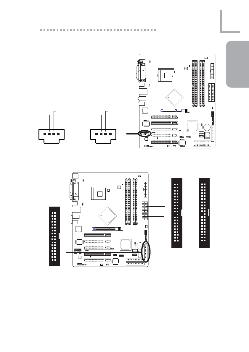
1.4.4 Game/MIDI Port
2
1
"
15
Page 11
1.4.5 Internal Audio Connectors
Quick Setup Guide
1
Guide
Quick Setup
Ground Ground
Left audio
channel
14
Right audio
channel
CD-in
Ground Ground
Left audio
channel
14
Right audio
channel
"
AUX-in
1.4.6 FDD and IDE Disk Drive Connectors
34
33
!
21
FDD
IDE 1
IDE 2
40
39
!
!
21
40
39
21
IDE 1IDE 2
11
Page 12
1
Quick Setup Guide
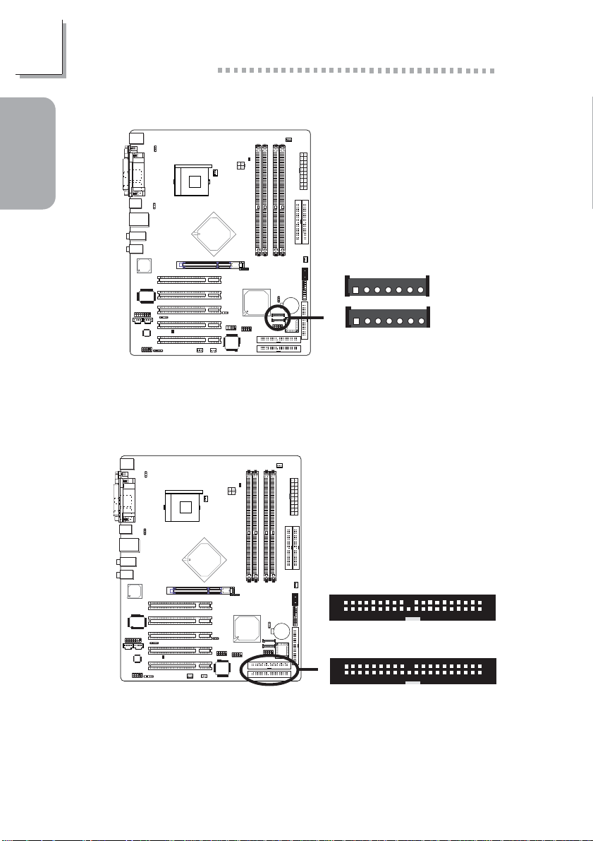
1.4.7 Serial ATA Connectors
Guide
Quick Setup
RXP
SATA 2
SATA 1
GND
17
17
!
TXP
RXN
TXN
GND
GND
The ICH5R south bridge chip allows configuring RAID on serial ATA
drives. It supports RAID 0 and 1.
1.4.8 RAID IDE Disk Drive Connectors
!
2
1
2
1
RAID 2
RAID 1
40
39
40
39
12
The HighPoint RAID controller allows configuring RAID on hard drives
connected to these RAID IDE connectors. It supports RAID 0, 1, 0+1
and 1.5.
Page 13
1.4.9 IrDA Connector
IRRX
N. C.
Ground
VCC
IRTX
Quick Setup Guide
1
Guide
Quick Setup
15
"
1.4.10 EZ Touch Switches (Power Switch and Reset
Switch)
Power Switch
!
The presence of the power switch and reset switch on the system
board are user-friendly especially to DIY users. They provide convenience in powering on and/or resetting the system while fine tuning the
system board before it is installed into the system chassis.
Reset Switch
13
Page 14
1
Quick Setup Guide
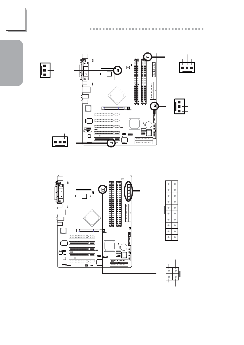
1.4.11 Cooling Fan Connectors
Guide
Quick Setup
1
3
Chip fan
On/Off
Power
Sense
!
Power
Ground
!
Sense
13
CPU fan
Power
On/Off
Sense
13
Second fan
!
1.4.12 Power Connectors
!
1
!
3
Chassis fan
3.3V
-12V
Ground
PS-ON
Ground
Ground
Ground
-5V
+5V
+5V
+12V
Ground
1
!
24
Ground
+12V
12011
10
Ground
Power
N. C.
3.3V
3.3V
Ground
+5V
Ground
+5V
Ground
PW-OK
5VSB
+12V
3
14
The system board requires a minimum of 250 Watt power supply to
operate. Your system configuration (amount of memory, add-in cards,
peripherals, etc.) may exceed the minimum power requirement. To ensure that adequate power is provided, use a 300 Watt (or greater)
power supply.
Page 15

1.4.13 Wake-On-LAN Connector
Quick Setup Guide
Ground
WOL
+5VSB
1
Guide
Quick Setup
!
1
3
The 5VSB power source of your power supply must support ≥720mA.
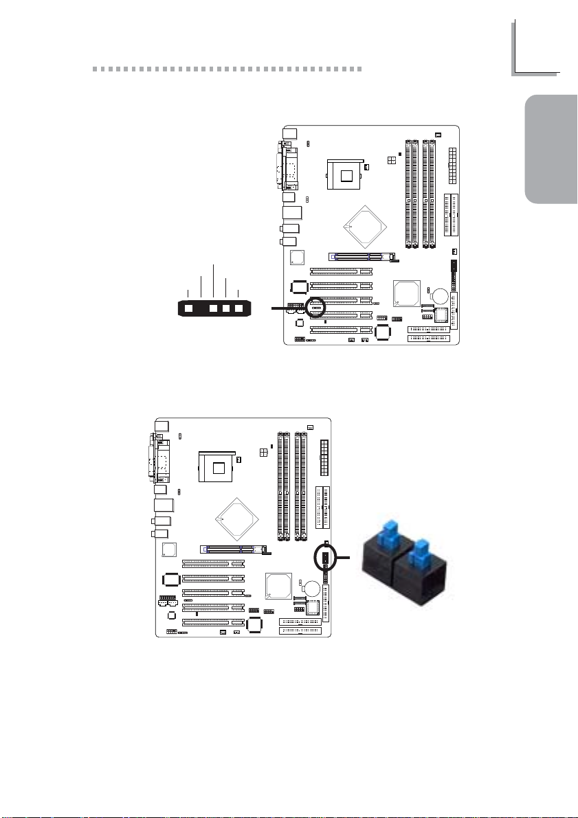
1.4.14 LEDs
DIMM Standby
Power LED
D-LED1-
D-LED2-
D-LED3-
D-LED4-
D-LED2+
D-LED3+
D-LED4+
N. C.
Key
Diagnostic LED
PCI Standby
Power LED
!
2
1
D-LED1+
10
9
15
Page 16

1
Quick Setup Guide
Early program chipset register before POST.
Guide
Quick Setup
Testing memory presence.
Detecting memory size.
No memory present.
Programming DRAM tim-
ing register.
Calculating DRAM size
variable including row, column and bank.
Initializing JEDEC of current DRAM row.
Checking CMOS checksum
and batter y.
Initializing the clock generator.
Initializing USB.
LED 1
On
Off
On
Off
On
Off
On
Off
On
Off
LED 2
Off
On
On
Off
Off
On
On
Off
Off
On
LED 3
Off
Off
Off
On
On
On
On
Off
Off
Off
LED 4
Off
Off
Off
Off
Off
Off
Off
On
On
On
16
Testing all memory
(cleared all extended
memory to 0).
Initializing the onboard Super IO.
Detecting and installing an
IDE device.
Final initialization.
Booting the system.
On
Off
On
Off
On
On
Off
Off
On
On
Off
On
On
On
On
On
On
On
On
On
Page 17

1.4.15 Front Panel Connectors
Quick Setup Guide
2019
SPEAKER
1
Guide
Quick Setup
HD-LED
(Primary/Secondary IDE LED)
Reserved
ATX-SW
(ATX power switch)
Reserved
RESET
(Reset switch)
SPEAKER
(Speaker connector)
PWR-LED
(Power/Standby LED)
J5
A TX-SW
!
PWR-LED
Pin
Pin Assignment
3
HDD LED Power
5
HDD
14
N. C.
16
N. C.
8
PWRBT+
10
PWRBT-
18
N. C.
20
N. C.
7
Ground
9
H/W Reset
13
Speaker Data
15
N. C.
17
Ground
19
Speaker Power
2
LED Power (+)
4
LED Power (+)
6
LED Power (-) or Standby Signal
RESET
HD-LED
2
1
17
Page 18

2
English
English
Chapter 2 - English
2.1 Features and Specifications
Processor
• Intel® Pentium® 4 Processor with Hyper-Threading Technology
- 800MHz/533MHz system data bus
• Intel® Pentium® 4 Northwood processor
- 533MHz/400MHz system data bus
• Intel® Celeron® Northwood processor
- 400MHz system data bus
Chipset
• Intel® 875P chipset
- Intel® 82875P Memory Controller Hub (MCH)
- Intel® 82801ER I/O Controller Hub (ICH5R)
System Memory
• Supports dual channel (128-bit wide) memory interface
- Each channel supports 2 DIMM sockets
• Supports up to 4GB system memor y
• Supports Dynamic mode to optimize system performance
• Synchronous operation with processor system bus
- PC2100/PC2700/PC3200 (DDR266/DDR333/DDR400)
with 800MHz FSB CPU (supports PAT mode). DDR333
will run at 320MHz memory frequency when used with
800MHz FSB CPU.
- Use PC2100/PC2700 (DDR266/DDR333) with 533MHz
FSB CPU
- Use PC2100 (DDR266) with 400MHz FSB CPU
• Suppor ts ECC/non-ECC DIMMs
• Supports unbuffered DIMMs
18
BIOS
• Award BIOS, Windows® 98SE/2000/ME/XP Plug and Play
compatible
• Genie BIOS provides:
- CPU/DRAM overclocking
Page 19

English
- AGP/PCI/SATA overclocking
- CPU/DIMM/AGP overvoltage
• Flash EPROM for easy BIOS upgrades
• Supports DMI 2.0 function
• 4Mbit flash memory
Energy Efficient Design
• ACPI STR (Suspend to RAM) function
• Wake-On-PS/2 Keyboard/Mouse
• Wake-On-USB Keyboard
• Wake-On-Ring
• Wake-On-LAN
• RTC timer to power-on the system
• AC power failure recovery
System Health Monitor Functions
• Monitors CPU/system temperature and overheat alarm
• Monitors CPU/1.5V/5VSB/VBAT/3.3V/5V/±12V voltages and
failure alarm
• Monitors the fan speed of the CPU fan, chip fan and second
fan; and failure alarm
• Automatic chip fan and second fan on/off control
• Read back capability that displays temperature, voltage and fan
speed
• CPU Fan Protection function monitors CPU fan during system
boot-up
• CPU Temperature Protection function monitors CPU temperature during system boot-up
2
English
Onboard Audio Features
• 20-bit stereo full-duplex codec with independent variable sampling rate
• High quality differential CD input
• True stereo line level outputs
• S/PDIF-in/out interface
• 6-channel audio output
19
Page 20

2
English
English
Onboard CSA Gigabit LAN Features
• Uses 82547EI Gigabit LAN CSA (Communication Streaming
Architecture) interface
• Integrated power management functions
• Full duplex suppor t at 10, 100 and 1000 Mbps
• Supports IEEE 802.3u auto-negotiation
• Supports wire for management
ATA RAID - Redundant Array of Independent Disk
• Uses HighPoint 372N RAID controller
• RAID 0, 1, 0+1 and 1.5
- RAID 1.5 performs data stripping and mirroring simultane-
ously using two drives only
• Two independent IDE channels support up to 4 drives
(ATA/33, ATA/66, ATA/100, ATA/133 or EIDE)
• Supports PIO modes 0/1/2/3/4, DMA modes 0/1/2 and
UDMA modes 0/1/2/3/4/5/6
PCI Bus Master IDE Controller
• Supports ATA/33, ATA/66 and ATA/100 hard drives
• PIO Mode 4 Enhanced IDE (data transfer rate up to 14MB/
sec.)
• Bus mastering reduces CPU utilization during disk transfer
• Suppor ts ATAPI CD-ROM, LS-120 and ZIP
20
ICH5R SATA IDE/RAID Interface
• Two SATA (Serial ATA) interfaces which are compliant with
SATA 1.0 specification (1.5Gbps interface)
• Suppor ts RAID 0 and 1
Processor Socket
• Socket 478
AGP (Accelerated Graphics Port)
• Suppor ts AGP 3.0 (AGP 4x and 8x) and AGP 2.0 (AGP 1x and
4x) spec.
• Supports 1.5V AGP 8x (2.13GB/sec.) and AGP 4x (1066MB/
sec.) add-in cards. AGP 2x and 3.3V AGP cards are not supported.
Page 21

English
Rear Panel I/O Ports (PC 99 color-coded connectors)
• 4 USB 2.0/1.1 por ts
• 1 RJ45 LAN por t
• 1 DB-9 serial por t
• 1 DB-25 parallel por t
• 1 mini-DIN-6 PS/2 mouse por t
• 1 mini-DIN-6 PS/2 keyboard port
• 2 S/PDIF RCA jacks (S/PDIF-in and S/PDIF-out)
• 3 audio jacks: line-out, line-in and mic-in
• 2 audio jacks for center/bass and rear out
I/O Connectors
• 2 connectors for 4 additional external USB 2.0/1.1 por ts
• 1 front audio connector for external line-out and mic-in jacks
• 1 connector for an external game/MIDI por t
• 2 internal audio connectors (CD-in and AUX-in)
• 1 S/PDIF connector for optical cable connection
• 1 connector for IrDA interface
• 2 RAID IDE connectors
• 2 Serial ATA connectors
• 2 IDE connectors
• 1 floppy connector
• 2 ATX power supply connectors
• 1 Wake-On-LAN connector
• CPU fan, chassis fan, second fan and chip fan connectors
• 1 diagnostic LED connector for 4 external diagnostic LEDs
display
• EZ touch switches (power switch and reset switch)
2
English
Expansion Slots
• 1 AGP slot
• 5 PCI slots
Compatibility
• PCI 2.2 and AC ’97 compliant
• Intel AGP version 3.0
21
Page 22

2
English
English
2.2 CMOS Reloaded
The CMOS Reloaded feature allows you to save different BIOS
configurations and when needed, allows you to conveniently restore one of these previously saved configurations. Select CMOS
Reloaded in the main menu of the Award BIOS then press <Enter>.
You can save up to two configurations - in the “User Define
Config 1” and “User Define Config 2” fields.
22
Saving a Configuration
After you have made the proper settings, move the cursor to
“Backup” of “User Define Config 1” then press <Enter>.
Restoring a Configuration
To restore one of the previously saved configurations, move the
cursor to “Load” of “User Define Config 1” then press <Enter>.
Renaming a Configuration
The default name given in the “User Define Config 1” field is
“Config 1” and “Config 2” in the “User Define Config 2” field. To
rename, move the cursor to “Rename” then press <Enter>. You
can enter up to 16 characters.
To save another configuration, repeat the procedures above but
this time, in the “User Define Config 2” field.
Page 23

2.3 Package Checklist
The system board package contains the following items:
! One LANPARTY PRO875B system board
! One LANPARTY PRO875B user’s manual
! One LANPARTY Features user’s manual
! Two IDE round cables
! One floppy round cable
! Two serial ATA data cables
! One serial ATA power cable
! One card-edge bracket mounted with a game/MIDI port
! One PC Transpo kit
! One FrontX device equipped with:
- Two USB 2.0/1.1 por ts
- One line-out jack
- One mic-in jack
- Four diagnostic LEDs
! One I/O shield
! One thermal paste
! One LANPARTY sticker
! One case badge
! One pack of jumper caps (five 2.54mm jumper caps)
! One “HighPoint 372 N RAID Drivers” diskette
! One “Intel ICH5R RAID Dr iver” diskette
! One “Mainboard Utility” CD
! One “WinDVD/WinRIP Utility” CD
English
2
English
If any of these items are missing or damaged, please contact your
dealer or sales representative for assistance.
Please refer to the LANPARTY Features manual for more information on the FrontX device.
23
Page 24

3
Français
Chapter 3 - Français
3.1 Caractéristiques et Spécifications
Processeur
• Les processeurs Intel® Pentium® 4 avec la Technologie HyperThreading - 800MHz/533MHz vitesse du bus
• Processeur Intel® Pentium® 4 Northwood
- 533MHz/400MHz vitesse du bus
• Processeur Intel® Celeron® Northwood
- 400MHz vitesse du bus
Chipset
• Intel® 875P chipset
- Intel® 82875P Controlleur du Mémoire (MCH - Memory
Controller Hub)
- Intel® 82801ER I/O Controleur Entrée/Sorrtie (ICH5R -
I/O Controller Hub)
Français
Français
24
Mémoire Système
• Suppor t d’interface de la mémoire à deux canaux (128-bit)
- Chaque canal suppor te 2 sockets DIMM
• Suppor t de 4GB de mémoire système
• Support Mode Dynamique
• Opération synchrone avec le bus système du processeur
- PC2100/PC2700/PC3200 (DDR266/DDR333/DDR400)
avec un processeur à 800MHz de FSB (support mode
PAT). La DDR333 peut marcher à 320MHz de fréquence
de mémoire si utilisée avec un processeur à 800MHz de
FSB.
- Utilisez la PC2100/PC2700 (DDR266/DDR333) avec un
processeur à 533MHz de FSB
- Utilisez la PC2100 (DDR266) avec un processeur à
400MHz de FSB
• Suppor t des barrettes DIMM ECC/non-ECC
• Suppor t des barrettes DIMM sans tampon
Page 25

Français
BIOS
• Compatible avec Award BIOS, Windows® 98SE/2000/ME/XP
Plug and Play
• Genie BIOS:
- Overclocking de CPU/DRAM
- Overclocking de AGP/PCI/SATA
- Contrôle du voltage de CPU/DIMM/AGP
• EPROM Flash pour une mise à niveau facile du BIOS
• Suppor te la fonction DMI 2.0
• Mémoire Flash 4Mbit
Design à Haut Rendement Énergétique
• ACPI STR (Suspend to RAM) fonction
• Réveil-Sur-PS/2 Clavier/Souris
• Eveil Clavier USB
• Eveil Sonnerie
• Réveil Par Le Réseau
• Minuterie RTC pour allumer le système
• Récupération après Défaillance d’Alimentation CA
3
System Health Monitor Fonctions
• Gère l’alarme de température et de surchauffe de CPU/
système
• Gère l’alarme de voltage et d’échec de CPU/1.5V/5VSB/VBAT/
3.3V/5V/±12V
• Gère la vitesse de ventilateur du ventilateur de CPU, chip et
second; et alarme de défaillance.
• Contrôle automatique de ventilateur de chip/second et
marche/arrêt de ventilateur
• Capacité de relecture qui affiche la température, le voltage et
la vitesse de ventilateur
• La Fonction de la Defense du Ventilateur de Processeur observe le travail du ventilateur pendant le chargement du
système
• La Fonction de Defense du Processeur de la Surchauffe observe la temperature du processeur pendant le chargement
du système
Français
25
Page 26

3
Français
Caractéristiques Audio sur Carte
• Codec full-duplex 20 bits stéréo avec fréquence
d’échantillonnage variable indépendante
• Entrée CD différentielle de haute qualité
• Sorties de niveau de lignes stéréo vraies
• Interface entrée/sortie S/PDIF
• Sortie audio 6-canaux
Fonctionnalités Onboard CSA Gigabit LAN
Français
• Utilise le contrôleur 82547EI Gigabit LAN CSA (Communication Streaming Architecture)
• Fonctions de gestion d’alimentation intégrées
• Suppor t Full duplex à 10, 100 et 1000 Mbps
• Supporte l’auto négociation IEEE 802.3u
• Support câble pour la gestion
ATA RAID – Réseau Rendondant des Disques peu Chers
• Utilise le contrôleur HighPoint 372N RAID
• RAID 0, 1, 0+1 et 1.5
- RAID 1.5 effectue simultanément le stripping et le mirror-
ing des données en utilisant deux disques seulement
• Deux canaux IDE indépendents supportent jusqu’à 4 disques
(ATA/33, ATA/66, ATA/100, ATA/133 ou EIDE)
• Suppor te les modes PIO 0/1/2/3/4, DMA 0/1/2 et UDMA 0/1/
2/3/4/5/6
Contrôleur IDE de BUS Maître PCI
• Suppor te des disques durs ATA/33, ATA/66 et ATA/100
• IDE Améliorés Mode 4 PIO (vitesse de transfert de données
allant jusqu’à 14Mo/sec.)
• La gestion de Bus réduit l’utilisation du CPU pendant les
transfer ts sur disque
• Suppor te les CD-ROM ATAPI, LS-120 et ZIP
Français
26
Interface ICH5R SATA IDE/RAID
• Deux interfaces SATA (Serial ATA) compatibles avec la
spécification SATA 1.0 (interface1.5Gbps)
• Suppor t RAID 0 et 1
Page 27

Français
Socket Processeur
• Socket 478
AGP (Accelerated Graphics Port)
• Soutien des spécifications AGP 3.0 (AGP 4x et 8x) et AGP 2.0
(AGP 1x et 4x)
• Soutien des cartes supplémentaires 1.5V AGP 8x (2.13GB par
seconde) et AGP 4x (1066MB par seconde). Les cartes AGP
2x et 3.3V AGP ne sont pas soutenues.
Le Panneau des Ports Entrée/Sortie en Arrière
• 4 por ts USB 2.0/1.1
• 1 por t RJ45 LAN
• 1 por t de DB-9 série
• 1 por t parallèle DB-25
• 1 por t souris PS/2 mini-DIN-6
• 1 por t clavier PS/2 mini-DIN-6
• 2 S/PDIF RCA pr ises (S/PDIF-in et S/PDIF-out)
• 3 prises audio: line-out, line-in et mic-in
• 2 prises audio: center/bass et rear out
Connecteurs Entrée/Sortie
3
Français
• 2 connecteurs pour 4 por ts USB 2.0/1.1 supplémentaires
• 1 connecteur audio de l’avant pour la sortie ligne et l’entrée
micro
• 1 connecteur pour 1 game/MIDI externe
•2 connecteurs CD-in et AUX-in audio internes
• 1 S/PDIF l’assemblage pour l’adjonction de câble optique
• 1 connecteur pour interface IrDA
• 2 connecteurs RAID IDE
• 2 connecteurs Serial ATA
• 2 connecteurs IDE
• 1 connecteur de lecteur de disquettes
• 2 connecteurs d’alimentation ATX
• 1 connecteur Wake-On-LAN
• Connecteurs de ventilateurs de CPU, de châssis, de second et
de chip
• Un assemblage pour 4 exterieurs indicateurs diagnostiques
• EZ interrupteurs (bouton de power et reset)
27
Page 28

3
Français
3.2 CMOS Reloaded
Français
Logements d’Extension
• 1 slot AGP
• 5 slots PCI
Compatibilité
• Compatible PCI 2.2 et AC’97
• Intel AGP version 3.0
Le sous-menu CMOS Reloaded vous permet, si vous en avez
besoin, garder des différentes configurations pour pouvoir installer plus loin l’une des déjà gardées. Choisissez CMOS Reloaded dans le menu principal de Award BIOS et pressez <Enter>.
Vous pouvez garder pas plus de deux configurations – dans
“User Define Config 1” et “User Define Config 2”.
Français
28
La Conservation de la Configuration
Après finir tout installation necessaire, passez sur “Backup” dans
“User Define Config 1” et pressez <Enter>.
La Restitution de la Configuration
Pour restituer les configurations gardees passez sur “Load” dans
“User Define Config 1” et pressez <Enter>.
Page 29

Le Changement de Nom de la Configuration
Le système donne le nom “Config 1” à ce qu’on a gardé dans
“User Define Config 1” et le nom “Config 2” à ce qu’on a gardé
dans “User Define Config 2”. Pour changer le nom de ce que
vous gardez passez sur “Rename” et pressez <Enter>. Vous
pouvez introduire jusqu’aux 16 symboles.
Pour garder la seconde configuration il faut répéter les procedures si-dessus mais cette fois dans “User Define Config 2”.
3.3 Liste de Vérification de l’Emballage
L’emballage de la car te système contient les éléments suivants:
! 1 car te système de LANPARTY PRO875B
! 2 manuel utilisateur
! 2 câbles IDE ronds
! 1 câble rond floppy
! 2 câble sér ie ATA
! 1 câble d’alimentation série ATA
! 1 br acket avec un port game/MIDI
! 1 sac PC Transpo
! 1 kit FrontX
- 2 ports USB 2.0/1.1
- 1 jack de sortie ligne
- 1 jack d’entrée micro
- 4 indicateurs diagnostiques
! 1 shield I/O
! 1 pâte silicone (composé à base du silicone)
! 1 étiquette LANPARTY
! 1 case badge
! 1 package de cavaliers (5 cavaliers 2.54mm)
! 1 disquette “HighPoint 372 N RAID Drivers”
! 1 disquette “Intel ICH5R RAID Driver for WinXP”
! 1 CD “Mainboard Utility”
! 1 CD “WinDVD/WinRIP Utility”
Français
3
Français
Si l’un de ces éléments n’était pas dans l’emballage ou s’il était
endommagé, veuillez contacter votre revendeur ou votre
représentant. Veuillez vous reporter au manuel LANPARTY pour
plus d’information sur le périphérique FrontX.
29
Page 30

4
Deutsch
Chapter 4 - Deutsch
4.1 Leistungsmerkmale und Technische Daten
Prozessor
• Intel® Pentium® 4 Prozessor mit Hyper-Threading Technologie
- 800MHz/533MHz Systemdatenbus
• Intel® Pentium® 4 Northwood Prozessor
- 533MHz/400MHz Systemdatenbus
• Intel® Celeron® Northwood Prozessor
- 400MHz Systemdatenbus
Chipset
• Intel® 875P chipset
- Intel® 82875P Speichersteuerungs-Plattenmitte (MCH Memory Controller Hub)
- Intel® 82801ER I/O Steuerungsplattenmitte (ICH5R - I/O
Controller Hub)
Systemspeicher
Français
Deutsch
30
• Unterstützt 2-Kanal (128-bit breit) Speicherschnittstellen
- Jeder Kanal unterstützt 2 DIMM Steckplätze
• Unterstützt bis zu 4GB Systemspeicher
• Unterstützt Dynamische-Modus
• Synchroner Betrieb mit dem Prozessor Systembus
- PC2100/PC2700/PC3200 (DDR266/DDR333/DDR400) mit
800MHz FSB CPU (Unterstützt PAT-Modus). Im Betrieb mit
einer 800 MHz FSB CPU arbeitet DDR333-Speicher mit
einer Speichertaktfrequenz von 320 MHz.
- Verwenden Sie PC2100/PC2700 (DDR266/DDR333)
Speicher mit 533MHz FSB CPU’s.
- Verwenden Sie PC2100 (DDR266) Speicher mit 400MHz
FSB CPU’s.
• Unterstützt ECC/non-ECC DIMM
• Unterstützt ungepufferte DIMMs
Page 31

Deutsch
BIOS
• Kompatibilität mit Award BIOS, Windows® 98SE/2000/ME/XP
Plug and Play
• Genie BIOS:
- CPU/DRAM Übertaktung
- AGP/PCI/SATA Übertaktung
- CPU/DIMM/AGP Überspannung
• Flash EPROM für ein einfaches Aktualisieren des BIOS
• Unterstützung der DMI-2.0-Funktion
• Flash-Speicher (4Mbit)
Energomisches Design
• ACPI STR (Suspend to RAM) funktion
• Wecken bei Betätigung der PS/2 Tastatur/Maus
• Wecken bei USB-Tastatur
• Wecken bei Klingeln
• Wecken des Systems durch das Netzwerk
• RTC-Taktgeber zum Einschalten des Systems
• Wiederherstellung der Wechselstromversorgung nach einem
Ausfall
4
System Health Monitor Funktions
• Überwachung der Temperatur des CPU/Systems sowie
Warnsignal bei Überhitzung
• Überwachung der Spannungen des CPU/1.5V/5VSB/VBAT/3.3V/
5V/±12V sowie Warnsignal bei Ausfall
• Überwachung der Geschwindigkeit des CPU-Ventilators, ChipVentilators und Second-Ventilators und sendet ein Warnsignal
bei einem Ausfall aus
• Automatisches des Chip-Ventilators und Second-Ventilators
Ein-/Ausschalten des Ventilators
• Anzeige der Temperatur, Spannung und Geschwindigkeit des
Ventilator s
• Die Schutzfunktion des Lüfter vom Prozessor überwacht die
Arbeit des Lüfter während der Auslastung des Systems
• Die Schutzfunktion des Prozessors gegen die Überhitzung
Deutsch
31
Page 32

4
Deutsch
Audiomerkmale auf Platine
• 20-Bit-Stereo-Vollduplex-Codec mit unabhängiger und
variabler Abtastfrequenz
• Hochwertige CD-Differential-Eingabe
• Naturgetreue Stereo-Leitungspegel-Ausgabe
• S/PDIF-In/Aus-Schnittstelle
• 6-Kanal-Audioausgang
Merkmale des CSA Gigabit LAN auf Platine
Deutsch
• Benutzung des 82547EI Gigabit LAN CSA (Communication
Streaming Architecture) Verbindung
• Integrierte Power-Management-Funktionen
• Vollduplex-Unterstützung bei 10, 100 und 1000 Mbps
• Unterstützung der IEEE-802.3u-Auto-Negotiation
• Unterstützung des Leiters für das Management
ATA RAID - Redundant Array of Independent Disk
• Verwendet HighPoint 372N RAID Controller
• RAID 0, 1, 0+1 und 1.5
- RAID 1.5 leistet simultan Datenablösung und Spiegelung
bei Gebrauch von 2 Laufwerken.
• Zwei unabhängige IDE-Kanäle unterstützen bis zu 4 Laufwerke
(ATA/33, ATA/66, ATA/100, ATA/133 oder EIDE)
• Unterstützt PIO-Modi 0/1/2/3/4, DMA-Modi 0/1/2 und UDMAModi 0/1/2/3/4/5/6
PCI-Bus-Master-IDE-Controller
• Unterstützung der Festplatten ATA/33, ATA/66 und ATA/100
• Erweitertes IDE des PIO-Modus 4 (Datenübertragungsgeschwindigkeit von bis zu 14MB/Sek.)
• Verminderte CPU-Benutzung während Diskettenübertragung
dank dem Bus-Master.
• Unterstützung des ATAPI CD-ROMs, LS-120 und ZIP.
Français
32
ICH5R SATA IDE/RAID Schnittstelle
• Zwei SATA (Serial ATA) Schnittstellen, die der SATA 1.0
Spezifikation (1.5Gbps interface) entsprechen
• Unterstützt RAID 0 und 1
Page 33

Deutsch
Prozessor Socket
• Buchse 478
AGP (Accelerated Graphics Port)
• Unterstützt AGP 3.0 (AGP 4x und 8x) und AGP 2.0 (AGP 1x
und 4x) Spezifikationen
• Unterstützt 1.5V AGP 8x (2.13GB/sek.) und AGP 4x (1066MB/
sek.) Erweiterungskarten. AGP 2x und 3.3V AGP Karten
werden nicht unterstützt.
Ein-/Ausgabe-Porte an der Rückwand
• 4 USB 2.0/1.1-Anschlüsse
• 1 RJ45 LAN-Anschlüsse
• 1 serieller DB-9-Anschlüsse
• 1 DB-25-Parallelanschluß
• 1 Mini-DIN-6-Anschluß für eine PS/2-Maus
• 1 Mini-DIN-6-Anschluß für eine PS/2-Tastatur
• 2 S/PDIF RCA-Anschlüsse (S/PDIF-in und S/PDIF-out)
• 3 Audio-Anschlußbuchsen: line-out, line-in und mic-in
• 2 Audio-Anschlußbuchsen: center/bass und rear out
4
Ein-/Ausgabe-Steckverbinder
•2 Anschlußfassung für 4 zusätzliche externe USB 2.0/1.1-
Anschlüsse
• 1 Frontaudioanschluß für die externe Ausgangsleitung und den
Mikrofoneingang
• 1 Anschluß für eine externe game/MIDI Schnittstelle
• 2 interne Audioanschlüsse (CD-in und AUX-in)
• 1 S/PDIF Anschluß für die Verbindung des optischen Kabel
• 1 Anschluß für die IrDA-Schnittstelle
• 2 RAID-IDE-Anschlüsse
• 2 Serial-ATA-Anschlüsse
• 2 IDE-Anschlüsse
• 1 Floppy-Anschlüsse
• 2 Anschlußstecker für das ATX-Netzgerät
• 1 Anschlußstecker für Wecken durch LAN
• CPU-, Chassis-, Second- und Chip-ventilator-Anschlüsse
• Ein Anschluß für 4 diagnostischen Außenindikatoren
• EZ Umschaltern (der Knopf der Speisung und des Auslasses)
Deutsch
33
Page 34

4
Deutsch
Erweiterungssteckfasssungen
• 1 AGP-Einbauplätzen
• 5 PCI-Einbauplätzen
Kompatibilität
• Kompatibilität mit PCI 2.2 und AC’97
• Intel AGP, ver sion 3.0
4.2 CMOS Reloaded
Das Teilmenü CMOS Reloaded läßt Sie im Notfall die
verschiedenen Konfigurationen aufbewahren, um eine aus die
früher aufgesparten Konfigurationen im weiteren
wiederaufzubauen. Wählen Sie “CMOS Reloaded” im Award
BIOS Hauptmenü, und drüken Sie <Enter>.
Sie können bis zwei Konfigurationen im Feld “User Define Config
1“ und “User Define Config 2“ behalten.
Français
Deutsch
34
Die Erhaltung der Konfiguration
Nachdem Sie alle notwendigen Installationen beendet haben,
verlagern Sie den Cursor auf “Backup” in “User Define Config
1“ und drücken Sie <Enter>.
Die Wiederaufbau der Konfiguration
Um die früher aufgesparten Konfigurationen wiederaufzubauen,
verlagern Sie den Cursor auf “Load” in “User Define Config 1”
und drücken Sie <Enter>.
Page 35

Die Umbenennung der Konfiguration
Im Verschweigen wird die Erhaltung im Feld “User Define Config
1” als “Config 1” und im Feld “User Define Config 2” als “Config
2” genannt. Um die Erhaltung umzubenennen, verlagern Sie den
Cursor auf “Rename” und drücken Sie <Enter>. Sie können bis
16 Symbols einsetzen.
Für die Erhaltung der zweiten Konfiguration muß man die
beschriebenen Prozeduren wiederholen, aber, diesmal, im Feld
“User Define Config 2“.
4.3 Verpackungsliste
In der Verpackung der Systemplatine sind folgende Artikel
enthalten:
! 1 Systemplatine
! 2 Benutzerhandbuch
! 2 r unde IDE-Kabel
! 1 runde Floppy-Kabel
! 2 serial-ATA-Kabel
! 1 serial-ATA-Energiekabel-Kabel
! 1 Br acket mit einem Game/MIDI Port
! Ein PC Transpo-Satz
! Eine FrontX-Einrichtung
- Zwei USB 2.0/1.1 Porte, Ein Stecker vom Linienausgang, Ein
Stecker vom Mikrofon und 4 diagnostischen
Außenindikatoren
! Eine I/O-Schutzlatte
! Eine Silikonpaste (das Silikon als die Basis)
! Ein LANPARTY-Klebezettel
! Ein Abzeichen für das Gehäuse
! Ein Satz des Jumper ses (fünf 2.54mm Jumpers)
! 1 Diskette “HighPoint 372 N RAID Drivers”
! 1 Diskette “Intel ICH5R RAID Driver for WinXP”
! 1 CD mit “Mainboard Utility”
! Eine CD “WinDVD/WinRIP Utility”
Deutsch
4
Deutsch
Fehlt einer dieser Artikel oder weist einer dieser Artikel
Beschädigungen auf, wenden Sie sich an Ihren Händler oder
Vertreter. Nach genauerer Information über die Einrichtung von
FrontX schauen Sie die LANPARTY-Anleitung.
35
Page 36

5
Español
Chapter 5 - Español
5.1 Características y Especificaciones
Procesador
• Procesador Pentium® 4 de Intel® con la Tecnología HiperEnhebramiento
- 800MHz/533MHz canal de datos del sistema
• Procesador Intel® Pentium® 4 Northwood
- 533MHz/400MHz canal de datos del sistema
• Procesador Intel® Celeron® Northwood
- 400MHz canal de datos del sistema
Chipset
• Intel® 875P chipset
- Hub de Controlador Memoria de Intel® 82875P (MCH -
Memory Controller Hub)
- Hub de Controlador I/O de Intel® 82801ER (ICH5R - I/O
Controller Hub)
Español
36
Memoria de Sistema
• Se soporta el interfaz de dos canales (128-bites)
- Cada canal se sopor ta por 2 eslots DIMM
• Se sopor ta 4GB de la memoria
• Se soporta el modo dinamico (Dynamic mode)
• La operacion sincronica ñon el bus del sistema del
procesador
- PC2100/PC2700/PC3200 (DDR266/DDR333/DDR400) ñon
el procesador en el bus de 800MHz (se soporta
tecnologia de PAT). DDR333 va a funcionar en la
frecuencia de 320MHz usando el procesador con el bus
800MHz.
- Use Ud. PC2100/PC2700 (DDR266/DDR333) ñon el
procesador en el bus de 533MHz
- Uså PC2100 (DDR266) con procesador en el bus de
400MHz
• Sopor ta la memoria ECC/non-ECC DIMM
• Soporta modulos inseparados DIMM
Page 37

Español
BIOS
• Award BIOS, Windows® 98SE/2000/ME/XP Enchufar y Usar
compatible
• Genie BIOS:
- El impulso del procesador/DRAM
- El impulso AGP/PCI/SATA
- La instalacion de la tension del procesador/DIMM/AGP
• Parpadea EPROM para fácil actualización de BIOS
• Sopor ta la función de DMI 2.0
• Memoria Instante (4Mbitios)
Diseño Energia Eficiente
• ACPI STR (Suspend to RAM) función
• PS/2 Teclado/Ratón de Wake-On
• Teclado de Wake-On-USB
• Wake-On-Ring
• Wake-On-LAN
• Temporizador de RTC para encender el sistema
• Recuperación de Fracaso de Energía AC
Funciones de Monitor de Salud del Sistema
5
• Monitores de los CPU/sistema temperaturas y alarma
acalorada.
• Monitores de voltajes de CPU/1.5V/5VSB/VBAT/3.3V/5V/±12V
y alarma de fracaso.
• Vigila la velocidad del abanico del abanido del CPU, abanido
del chip y abanico de second; y alarma de fracaso.
• Control abanido del chip y abanico de second encendido/
apagado del abanico automático.
• Capacidad de Leer hacia atrás que presenta la temperatura,
voltaje y velocidad de abanico.
• La Función de la Protección del Ventilador del Procesador
controla el ventilador durante la carga del sistema
• La Función de la Protección del Procesador de
Recalentamiento controla la temperatura del procesador durante la carga del sistema
Español
37
Page 38

5
Español
Características de Audio En Tablero
• Codec dúplex completo estéreo de 20-bit con independiente
frecuencia de muestreo variable
• Alta calidad de entrada de CD diferencial
• Auténtico salidas de nivel de línea estéreo
• Interfáz de S/PDIF-in/out
• Output auricular de 6-canal
Características de CSA Gigabit LAN Interno
• Utiliza el rápido controlador 82547EI Gigabit LAN CSA
(Communication Streaming Architecture)
• Funciones de administración de energía integrado
• Sopor te dúplex completo en ambos 10, 100 y 1000 Mbps
• Soporta auto negociación de IEEE 802.3u
• Soporta alambre para la administración
ATA RAID – Arsenal Redundante Barato del Disco
• Se usa el controlador HighPoint 372N RAID
• RAID 0, 1, 0+1 y 1.5
- RAID 1,5 realiza simultaneamente el regimen “stripping” y
“mirroring” solo para dos discos
• Dos canales IDE independientes soportan hasta 4 discos
(ATA/33, ATA/66, ATA/100, ATA/133 o EIDE)
• Soporta modos 0/1/2/3/4 del PIO, modos 0/1/2/ de DMA y
modos 0/1/2/3/4/5/6 de UDMA
Español
38
Controlador de IDE Maestro de Bus PCI
• Sopor ta las unidades duras de ATA/33, ATA/66 y ATA/100
• PIO Modo 4 Realzada IDE (tasa de transferencia de dato
hasta 14MB/seg.)
• Controlación de Bus reduce la utilización de CPU durante la
trasferencia de disco
• Sopor ta ATAPI CD-ROM, LS-120 y ZIP
El Inerfaz ICH5R SATA IDE/RAID
• Dos interfaces SATA (Serial ATA) son obedientes con la
especificacion SATA 1.0 (el interfaz 1.5Gbps)
• Se sopor ta RAID 0 y 1
Page 39

Español
Procesador Zócalo
• Zócalo 478
AGP (Accelerated Graphics Port)
• Sopor ta especificaciones AGP 3.0 y AGP 2.0
• Soporta placas 1.5V AGP 8x (2.13Gb/seg.) è AGP 4x
(1066Mb/seg.). Tarjetas AGP, AGP 2x y 3.3V no se sopor tan.
Panel de reverso de conectores de entrada - Salida
• 4 puer tos de USB 2.0/1.1
• 1 puer to de RJ45 LAN
• 1 puer tos de serie DB-9
• 1 puer to paralelo de DB-25
• 1 puer to de ratón PS/2 mini-DIN-6
• 1 puer to de teclado mini-DIN-6 PS/2
• 2 enchufes de S/PDIF RCA (S/PDIF-in y S/PDIF-out)
• 3 enchufes de audio: line-out, line-in y mic-in
• 2 enchufes de audio: center/bass y rear out
I/O Conectores
5
• 2 conectores para 4 puer tos de USB 2.0/1.1 externo adicional
• 1 conectador audio delantero para la salida extrema de linea
y el micro
• 1 conector para un puer to de game/MIDI externa
• 2 conectores de CD-in y AUX-in audio interno
• 1 S/PDIF mortaja para conección de cable óptico
• 1 conector para interfaz de IrDA
• 2 conectores de RAID IDE
• 2 conectores de Serial ATA
• 2 conectores de IDE
• 1 conector de disquete
• 2 conectores de fuente de alimentación de ATX
• 1 conector de Wake-On-LAN
• 4 conectores de abanicos de CPU, chasis, second y chip
• Una mortaja para 4 indicadores diagnósticos externos
• EZ conmutadores (conmutadores de alimentación y reset)
Ranuras de Expansión
• 1 slot AGP y 5 slots PCI
Español
39
Page 40

5
Español
Compatibilidad
• Sumisión de PCI 2.2 y AC’97
• Versión 3.0 de Intel AGP
5.2 CMOS Reloaded
El submenú CMOS Reloaded permite conservar diferentes
configuraciónes y permite reconstituir una de las configuraciones
conservadas antes, cuando es necesario. Opte CMOS Reloaded
en menú principal de Award BIOS y aprete <Enter>. Vd puede
conservar hasta dos configuraciones – en los campos “User Define Config 1” y “User Define Config 2”.
Español
40
Conservación de Configuración
Después de realizar todos instalaciones necesarias mueva el cursor al “Backup” en “User Define Config 1” y aprete <Enter>.
Reconstitución de Configuración
Para reconstituir las configuraciónes conservadas antes mueva el
cursor al “Load” en “User Define Config 1” y aprete <Enter>.
Cambio de nombre de Configuración
Configuraciones conservadas se nombran automáticamente
“Config 1” en el campo “User Define Config 1” y “Config 2” en
el campo “User Define Config 2”. Para cambiar de nombre la
configuración mueva el cursor al “Rename” y aprete <Enter>. Vd
puede entrar hasta 16 símbolos.
Page 41

Para conservar otra configuración repita los procedimientos
descritos antes, pero en el campo “User Define Config 2”.
5.3 Lista de Chequeo del Paquete
El paquete del tablero de sistema contiene los siguientes
artículos:
! 1 tablero de sistema
! 2 manual de usuario
! 2 cables de flojo para IDE
! 1 cable de flojo para el disquette
! 2 cable serial ATA
! 1 cable de alimentacion serial ATA
! 1 placa con 1 puer to game/MIDI
! Un juego PC Transpo
! Un dispositivo FrontX
- Dos USB 2.0/1.1 por tes
- Una mortaja de line-out
- Una mortaja de mic-in
- 4 indicadores diagnósticos
! Una chapa protectora I/O
! Una pasta de silicón (compuesto silicón-basado)
! Una pegatina LANPARTY
! Una insignia en caja
! Un paquete de jumper caps (cinco 2.54mm jumper caps)
! 1 disquette flojo “HighPoint 372 N RAID Drivers”
! 1 disquette flojo “Intel ICH5R RAID Driver for WinXP”
! 1 CD de “Mainboard Utility”
! Un CD “WinDVD/WinRIP Utility”
Español
5
Si cualquieres de estos artículos están perdidos o dañados, favor
de ponerse en contacto con su tratante o representantes de
venta para la asistencia.
Para información mas detallada de dispositivo FrontX refiérase al
manual LANPARTY.
Español
41
Page 42

6
Русский
Глава Глава
Глава
Глава Глава
6.1 Характеристики и свойства6.1 Характеристики и свойства
6.1 Характеристики и свойства
6.1 Характеристики и свойства6.1 Характеристики и свойства
Русский
6 6
- -
6
6 6
ПроцессорПроцессор
Процессор
ПроцессорПроцессор
• Процессор Intel
Threading
- 800MHz/533MHz системная шина
• Процессор Intel® Pentium® 4 Northwood
- 533MHz/400MHz системная шина
• Процессор Intel® Celeron® Northwood
- 400MHz системная шина
ЧипсетЧипсет
Чипсет
ЧипсетЧипсет
• Intel® 875P chipset
- Intel® 82875P Memory Controller Hub (MCH)
- Intel® 82801ER I/O Controller Hub (ICH5R)
Оперативная ПамятьОперативная Память
Оперативная Память
Оперативная ПамятьОперативная Память
• Поддерживает двухканальный (128-битного)
интерфейс
- Каждый канал поддерживает 2 DIMM слота
• Поддерживает 4Гб оперативной памяти
• Поддерживает Динамический Режим
• Синхронная операция с системной шиной
процессора
- PC2100/PC2700/PC3200 (DDR266/DDR333/
DDR400) с процессором на шине 800MГц
(Поддерживает Режим PAT). DDR333 будет
работать на частоте 320MГц при использовании
процессора на шине 800MГц.
- Используйте PC2100/PC2700 (DDR266/DDR333) с
процессором на шине 533MГц
- Используйте PC2100 (DDR266) с процессором на
øèíå 400MÃö
• Поддерживает память ECC/non-ECC DIMM
• Поддерживает небуффер. модули DIMM
Русский языкРусский язык
-
Русский язык
- -
Русский языкРусский язык
®®
®
®®
Pentium
®®
®
®®
4 с технологией Hyper-
42
Page 43

Русский
BIOSBIOS
BIOS
BIOSBIOS
®®
®
• Award BIOS, Windows
Play
• Genie BIOS:
- Разгон Процессора/DRAM
- Разгон AGP/PCI/SATA
- Установка напряжения Процессора/DIMM/AGP
• Flash EPROM для обновления BIOS
• Поддерживает функцию DMI 2.0
• 4Mbit Flash Память
Энергомичный ДизайнЭнергомичный Дизайн
Энергомичный Дизайн
Энергомичный ДизайнЭнергомичный Дизайн
• ACPI STR (Suspend to RAM)
• Активизация На Движение Мыши
• Активизация На Нажатие Кнопки USB Клавиатуры
• Активизация На Входящий Звонок
• Активизация На Сетевое Событие
• RTC Таймер для Включения Системы
• Скачки Напряжения
Функции Мониторинга Состояния СистемыФункции Мониторинга Состояния Системы
Функции Мониторинга Состояния Системы
Функции Мониторинга Состояния СистемыФункции Мониторинга Состояния Системы
®®
98SE/2000/ME/XP Plug and
6
Русский
• Mониторинг температуры процессора/системы
• Mониторинг напряжений CPU/1.5V/5VSB/VBAT/3.3V/
5V/±12V
• Mониторинг скорости вращения вентилятора CPU/
chip/second
• Автоматическое управление chip/second
вентилятора системы
• Отображение температуры, напряжения и скорости
работы вентилятора
• Функция Защиты Вентилятора Процессора следит
за работой вентилятора во время загрузки системы
• Функция Защиты Процессора от Перегрева
отслеживает температуру процессора во время
загрузки системы
Встроенный ЗвукВстроенный Звук
Встроенный Звук
Встроенный ЗвукВстроенный Звук
• Полнодуплексный 20-битный стерео кодек с
независимым изменением частоты сжатия
43
Page 44

6
Русский
Русский
• Высококачественный дифференциальный CD вход
• Настоящий линейный стерео выход
• интерфейса S/PDIF-in и S/PDIF-out
• 6-и канальный звуковой выход
Встроенные сетевые функцииВстроенные сетевые функции
Встроенные сетевые функции
Встроенные сетевые функцииВстроенные сетевые функции
• Быстрый контроллер 82547EI Gigabit LAN CSA
(Communication Streaming Architecture)
• Встроенные функции управления питанием
• Полнодуплексная поддержка на 10, 100 и 1000
Mbps
• Поддерживает IEEE 802.3u auto-negotiation
• Работа через шнур управления
AA
TT
A RAID – Недорогой Дисковый МассивA RAID – Недорогой Дисковый Массив
A
T
A RAID – Недорогой Дисковый Массив
AA
TT
A RAID – Недорогой Дисковый МассивA RAID – Недорогой Дисковый Массив
• Использует контроллер HighPoint 372N RAID
• RAID 0, 1, 0+1 è 1.5
- RAID 1.5 одновременно использует режим «strip-
ping» и «mirroring» только для двух дисков
• Два независимых IDE канала поддерживают до 4
дисков (ATA/33, ATA/66, ATA/100, ATA/133 или EIDE)
• Поддерживает PIO режимы 0/1/2/3/4, DMA режимы
0/1/2 и UDMA режимы 0/1/2/3/4/5/6
44
Контроллер PCI IDE Мастер ШиныКонтроллер PCI IDE Мастер Шины
Контроллер PCI IDE Мастер Шины
Контроллер PCI IDE Мастер ШиныКонтроллер PCI IDE Мастер Шины
• Поддерживает жесткие диски ATA/33, ATA/66 и ATA/
100
• PIO Mode 4 Расширенный IDE (скорость передачи
данных до 14МБ/сек.)
• Мастеринг шины снижает нагрузку на центральный
процессор
• Поддерживает ATAPI CD-ROM, LS-120 и ZIP
Интерфейс ICH5R SAИнтерфейс ICH5R SA
Интерфейс ICH5R SA
Интерфейс ICH5R SAИнтерфейс ICH5R SA
• Два интерфейса SATA (Serial ATA) совместимы со
спецификацией SATA 1.0 (интерфейс 1.5Gbps)
• Поддерживает RAID 0 и 1
ЧипсетЧипсет
Чипсет
ЧипсетЧипсет
• Socket 478
Socket Socket
Socket
Socket Socket
TT
A IDE/RAIDA IDE/RAID
T
A IDE/RAID
TT
A IDE/RAIDA IDE/RAID
Page 45

Русский
AGP (Accelerated Graphics Port)AGP (Accelerated Graphics Port)
AGP (Accelerated Graphics Port)
AGP (Accelerated Graphics Port)AGP (Accelerated Graphics Port)
• Поддерживает спецификации AGP 3.0 (AGP 4x и 8x)
и AGP 2.0 (AGP 1x и 4x)
• Поддерживает карты 1.5V AGP 8x (2.13Гб/сек.) и
AGP 4x (1066Mб/сек.). AGP карты AGP 2x и 3.3V не
поддерживаются.
Порты Ввода/Вывода (I/O) задней панелиПорты Ввода/Вывода (I/O) задней панели
Порты Ввода/Вывода (I/O) задней панели
Порты Ввода/Вывода (I/O) задней панелиПорты Ввода/Вывода (I/O) задней панели
• 4 USB 2.0/1.1 порта
• 1 RJ45 LAN ïîðò
• 1 внешнего DB-9 порта
• 1 внешнего DB-25 параллельный порт
• 1 ìèíè-DIN-6 PS/2 ïîðò äëÿ ìûøè
• 1 мини-DIN-6 PS/2 порт для клавиатуры
• 2 S/PDIF RCA звука (S/PDIF-in и S/PDIF-out)
• 3 гнезда для звука: выход, вход и микрофон
• 2 гнезда для звука: center/bass и rear out
Разъемы Ввода/ВыводаРазъемы Ввода/Вывода
Разъемы Ввода/Вывода
Разъемы Ввода/ВыводаРазъемы Ввода/Вывода
• 2 разъем для 4-х дополнительных внешних USB 2.0/
1.1 портов
• 1 передний аудио разъем для внешнего линейного
выхода и микрофона
• 1 разъем для внешнего game/MIDI порта
• 2 внутренних звуковых разъема (CD-in и AUX-in)
• 1 S/PDIF разъем для присоединения оптического
кабеля
• 1 разъем для интерфейса IrDA
• 2 RAID IDE разъема
• 2 Serial ATA разъема
• 2 IDE разъема
• 1 разъем для подключения двух дисководов до
2.88Má
• 2 разъема питания ATX
• 1 Wake-On-LAN (Активизация на сетевое событие)
• Разъемы для вентилятора CPU/chassis/second/chip
• Один разъем для 4-х внешних диагностических
индикаторов
• EZ переключатели (кнопка питания и сброса)
6
Русский
45
Page 46

6
Русский
Русский
СлотыСлоты
Слоты
СлотыСлоты
• 1 AGP слотов
• 5 PCI слотов
СовместимостьСовместимость
Совместимость
СовместимостьСовместимость
• PCI 2.2 è AC ’97
• Intel AGP версии 3.0
6.2 CMOS Reloaded6.2 CMOS Reloaded
6.2 CMOS Reloaded
6.2 CMOS Reloaded6.2 CMOS Reloaded
Подменю CMOS Reloaded позволяет вам, при
необходимости, сохранять различные конфигурации,
чтобы в дальнейшем восстановить одну из ранее
сохраненных конфигураций. Выберите CMOS Reloaded
в главном меню Award BIOS и нажмите <Enter>.
Вы можете сохранить до двух конфигураций – в поле
“User Define Config 1” и “User Define Config 2”.
46
Сохранение КонфигурацииСохранение Конфигурации
Сохранение Конфигурации
Сохранение КонфигурацииСохранение Конфигурации
После того, как вы завершили все необходимые
установки, переместите курсор на “Backup” в “User
Define Config 1” и нажмите <Enter>.
Восстановление КонфигурацииВосстановление Конфигурации
Восстановление Конфигурации
Восстановление КонфигурацииВосстановление Конфигурации
Чтобы восстановить ранее сохраненные
конфигурации, переместите курсор на “Load” в “User
Define Config 1” и нажмите <Enter>.
Page 47

Переименование КонфигурацииПереименование Конфигурации
Переименование Конфигурации
Переименование КонфигурацииПереименование Конфигурации
По умолчанию, сохранению в поле “User Define Config
1” дается имя “Config 1” и “Config 2” в поле “User Define
Config 2”. Чтобы переименовать сохранение,
переместите курсор на “Rename” и нажмите <Enter>.
Вы можете ввести до 16 символов.
Для сохранения второй конфигурации следует
повторить описанные процедуры, но, на этот раз, в
поле “User Define Config 2”.
6.3 Комплектация6.3 Комплектация
6.3 Комплектация
6.3 Комплектация6.3 Комплектация
Комплектация поставки материнской платы:
! Материнская плата
! Руководство пользователя
! Два IDE шлейфа для IDE
! Один шлейф для флоппи диска
! Два шлейф Serial ATA
! Один шлейф шнуром питания Serial ATA
! Задняя планка с game/MIDI порта
! Один набор PC Transpo
! Одно устройство FrontX
- Два USB 2.0/1.1 порта
- Один разъем линейного выхода
- Один разъем микрофона
- 4-х внешних диагностических индикаторов
! Одна защитная планка I/O
! Одна силиконовая паста (на основе силикона)
! Одна наклейка LANPARTY
! Один значок на корпус
! Одна упаковка джамперов (пять 2.54mm джамперов)
! Одна дискета “HighPoint 372 N RAID Drivers”
! Одна дискета “Intel ICH5R RAID Driver for WinXP”
! Îäèí CD ñ “Mainboard Utility”
! Îäèí CD äèñê “WinDVD/WinRIP Utility”
Русский
6
Русский
Если в комплекте из этого чего-то не хватает или чтото испорчено, пожалуйста, свяжитесь со своим
дилером или продавцом.За более подробной
информацией об устройстве FrontX обратитесь к
руководству LANPARTY.
47
 Loading...