

Page 1

Rev. A+
System Board User’s Manual
Carte Mère Manuel Pour Utilisateur
System-Platine Benutzerhandbuch
Manual del Usuario de Placas Base
Руководство ПользователяРуководство Пользователя
Руководство Пользователя
Руководство ПользователяРуководство Пользователя
935-NF2001-500
77500335
Page 2

Copyright
This publication contains information that is protected by copyright. No part of it may be reproduced in any form or by any
means or used to make any transformation/adaptation without
the prior written permission from the copyright holders.
This publication is provided for informational purposes only. The
manufacturer makes no representations or warranties with respect to
the contents or use of this manual and specifically disclaims any
express or implied warranties of merchantability or fitness for any
particular purpose. The user will assume the entire risk of the use or
the results of the use of this document. Further, the manufacturer
reserves the right to revise this publication and make changes to its
contents at any time, without obligation to notify any person or
entity of such revisions or changes.
© 2003. All Rights Reserved.
Trademarks
Microsoft® MS-DOS®, WindowsTM, Windows® 95, Windows® 98,
Windows® 98 SE, Windows® ME, Windows® 2000, Windows NT
4.0 and Windows® XP are registered trademarks of Microsoft
Corporation. AMD, AthlonTM XP, AthlonTM and DuronTM are registered trademarks of Advanced Micro Devices, Inc. nVIDIA® is a
registered trademark of NVIDIA Corporation. Award is a registered trademark of Award Software, Inc. Other trademarks and
registered trademarks of products appearing in this manual are
the properties of their respective holders.
Caution
To avoid damage to the system:
• Use the correct AC input voltage range
To reduce the risk of electric shock:
• Unplug the power cord before removing the system chassis
cover for installation or servicing. After installation or servicing,
cover the system chassis before plugging the power cord.
..
.
..
®
Page 3

Battery:
• Danger of explosion if battery incorrectly replaced.
• Replace only with the same or equivalent type recommend
the manufacturer.
• Dispose of used batteries according to the battery
manufacturer’s
Joystick or MIDI port:
• Do not use any joystick or MIDI device that requires more than
10A current at 5V DC. There is a risk of fire for devices that
exceed this limit.
instructions.
FCC and DOC Statement on Class B
This equipment has been tested and found to comply with the limits
for a Class B digital device, pursuant to Part 15 of the FCC rules.
These limits are designed to provide reasonable protection against
harmful interference when the equipment is operated in a residential
installation. This equipment generates, uses and can radiate radio
frequency energy and, if not installed and used in accordance with
the instruction manual, may cause harmful interference to radio
communications. However, there is no guarantee that interference
will not occur in a particular installation. If this equipment does cause
harmful interference to radio or television reception, which can be
determined by turning the equipment off and on, the user is
encouraged to try to correct the interference by one or more of the
following measures:
by
• Reorient or relocate the receiving antenna.
• Increase the separation between the equipment and the receiver.
• Connect the equipment into an outlet on a circuit different from
that to which the receiver is connected.
• Consult the dealer or an experienced radio TV technician for
help.
Notice:
1. The changes or modifications not expressly approved by the
party responsible for compliance could void the user's authority
to operate the equipment.
2. Shielded interface cables must be used in order to comply with
the emission limits.
Page 4

1
Quick Setup Guide
Table of Contents
Guide
Quick Setup
Quick Setup Guide.................................................
Chapter 2
English.........................................................................
Chapter 3
Français........................................................................
Chapter 4
Deutsch................................................................................
Chapter 5
Español...............................................................................
Chapter 6
Русский..................................................................
Chapter 1
5
16
22
28
34
40
The user’s manual in the provided CD contains detailed information about the system
board. If, in some cases, some information doesn’t match those shown in this manual, this
manual should always be regarded as the most updated version.
Le manuel d’utilisateur dans le CD muni contient renseignement détaillé au sujet de carte
de système. Si, en quelque cas, quelque renseignement n’appareille de ce que dit dans ce
manuel, ce manuel doit toujours être considéré comme la plus nouvelle version.
Das Benutzerhandbuch in der angebotenen CD enthält detaillierte Informationen über die
Hauptplatine. Wenn in manchen Fällen manche Informationen nicht denjenigen Informationen
dargestellt in diesem Handbuch entsprechen, soll dieses Handbuch als die meist
aktualisierte Ausgabe gelten.
El uso explicativo contene información detalle sobre la sistema board en el CD preparativo.
Si en algún caso, la información no es igual con el uso explicativo, necesita ver el uso
explicativo, esque es más nuevo.
В руководстве пользователя на предоставляемом CD диске содержится
подробная информация о материнской плате. Иногда напечатанное
руководство может не совпадать руководством на CD, так как последнее
наиболее часто обновляется и является самым свежим.
4
Page 5
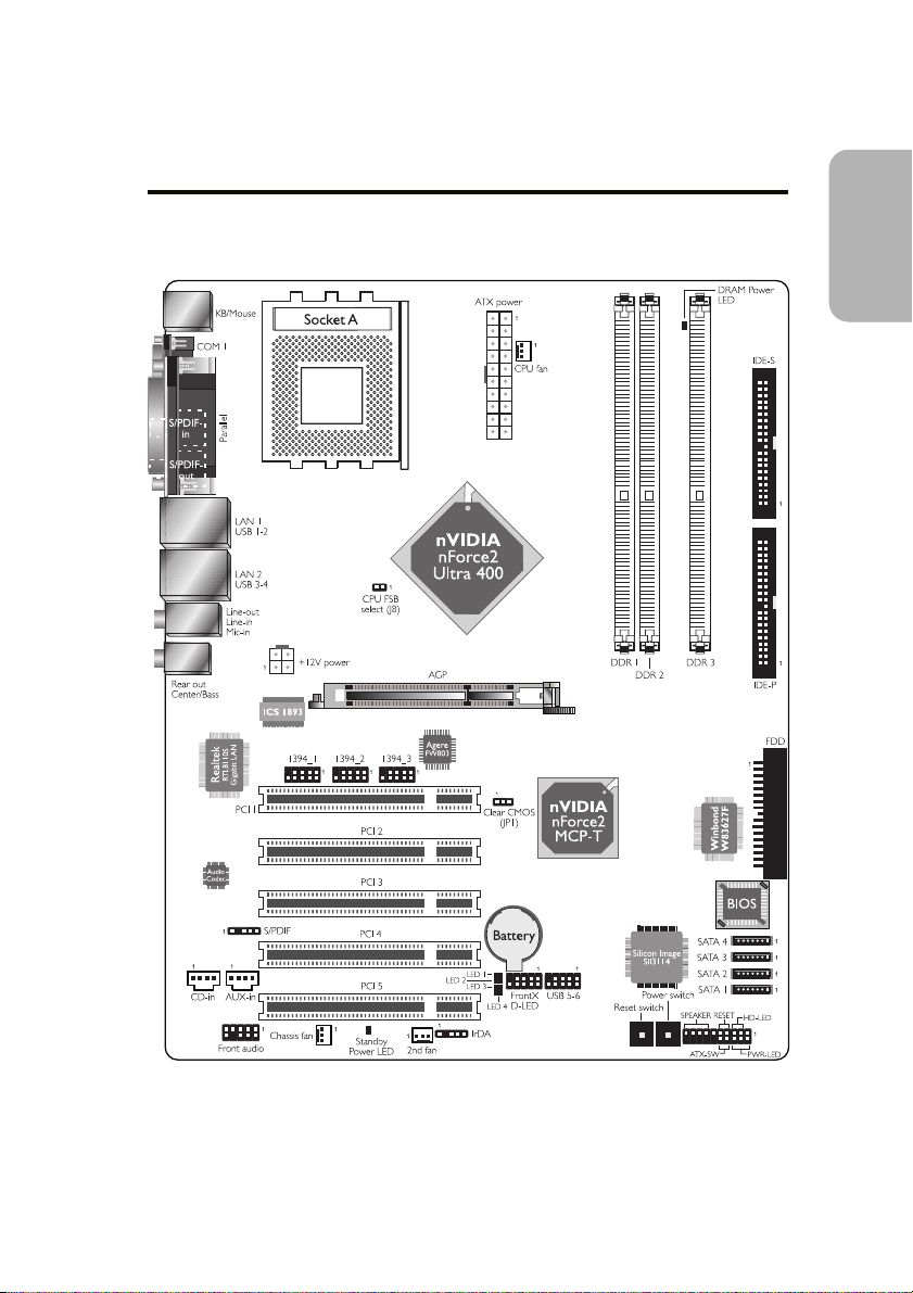
Chapter 1 - Quick Setup Guide
1.1 System Board Layout
Quick Setup Guide
1
Guide
Quick Setup
5
Page 6
1
Quick Setup Guide
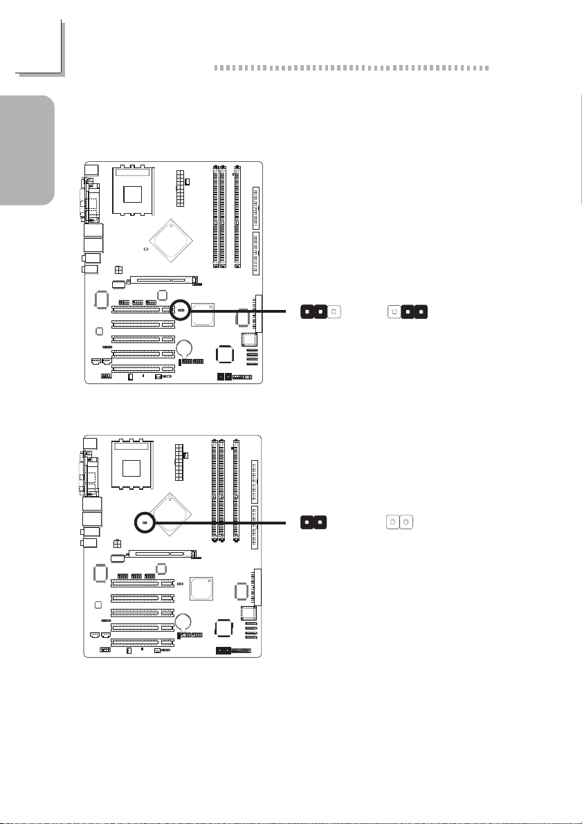
1.2 Jumpers
1.2.1 Clearing CMOS Data
Guide
Quick Setup
1.2.2 CPU’s FSB Select
JP1
!
1-2 On: Normal
(default)
21
J8
!
On: Other CPUs
(default)
312312
2-3 On:
Clear CMOS Data
21
Off: 100MHz
6
Page 7
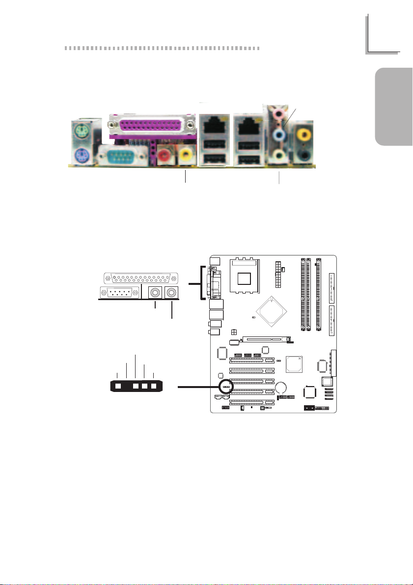
1.3 Rear Panel I/O Ports
Quick Setup Guide
1
PS/2
Mouse
PS/2
K/B
Parallel
COM S/PDIF-in
S/PDIF-out
1.4 I/O Connectors
1.4.1 S/PDIF-in/out Jacks
S/PDIF-in
S/PDIF-out
SPDIF out
Key
GND
VCC
15
SPDIF in
"
"
J2
LAN 1
USB 1-2
LAN 2
USB 4
USB 3-4
Mic-in
Line-out
Line-in
Center/Bass
Guide
Quick Setup
Rear out
7
Page 8

1
Quick Setup Guide
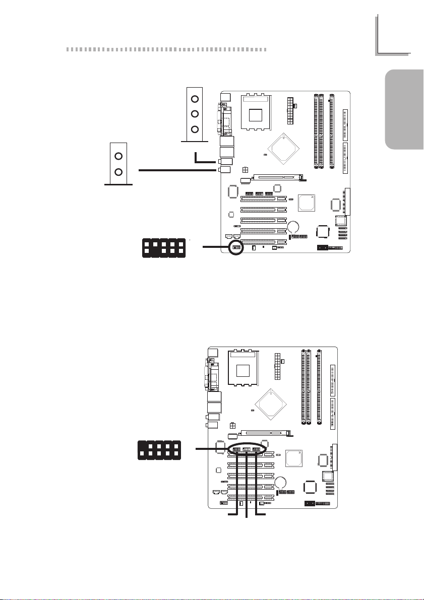
1.4.2 Universal Serial Bus Ports
Guide
USB 2
USB 1
Quick Setup
USB 4
USB 3
1.4.3 Internal Audio Connectors
"
"
!
9
Ground
+Data
KeyN. C.
+Data
Ground
USB 5-6
-Data
-Data
1
210
VCC VCC
8
Ground Ground
Left audio
channel
14
Right audio
channel
CD-in
Left audio
Ground Ground
Right audio
channel
14
channel
"
AUX-in
Page 9
1.4.4 Audio
Center/Bass
10
"
9
Rear out
1.4.5 IEEE 1394
Mic-in
Line-in
Line-out
AuD_L_Out
AuD_R_Out
MicGND
N. C.
Mic Power
1
2
Key
AuD_Vcc
AuD_L_Return
AuD_R_Return
"
"
Front audio
Quick Setup Guide
1
Guide
Quick Setup
10
9
VCC VCC
TPB- TPB+
Ground
1
"
2
TPA-
1394_2
1394_31394_1
TPA+
Ground
KeyShield
9
Page 10
1
Quick Setup Guide
1.4.6 SATA (Serial ATA) Connectors
Guide
Quick Setup
1.4.7 IrDA Connector
IRRX
N. C.
Ground
VCC
15
IRTX
"
SATA 4
SATA 3
SATA 1
SATA 2
TXN
GND
TXP
1
GND
7
RXP
RXN
GND
10
Page 11

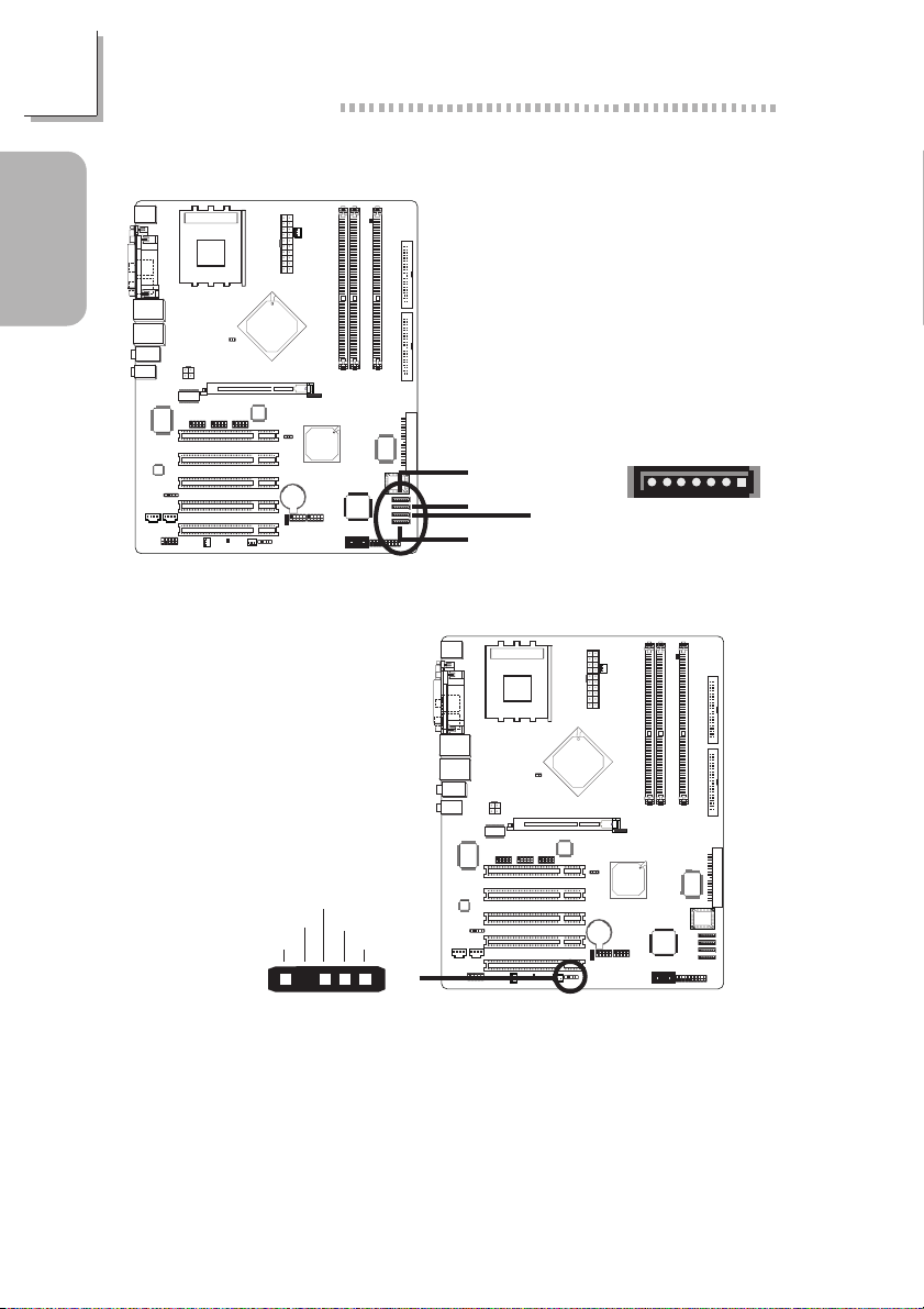
1.4.8 Cooling Fan Connectors
Quick Setup Guide
1
1
!
3
CPU fan
Power
1
3
Chassis fan 2nd fan
Ground
Power
Sense
!
Ground
13
!
1.4.9 DRAM Power LED and Standby Power LED
DRAM Power
LED
Ground
Power
Sense
Ground
Guide
Quick Setup
Standby Power
LED
11
Page 12
1
Quick Setup Guide
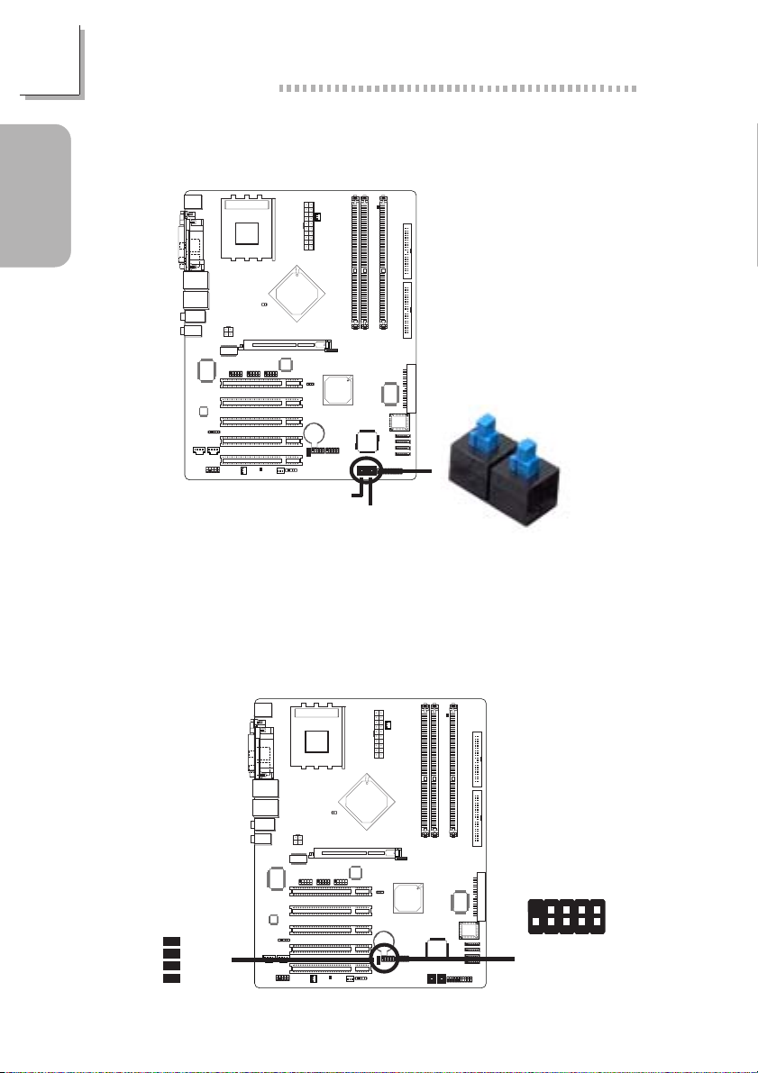
1.4.10 EZ Touch Switches (Reset Switch and Power
Guide
Quick Setup
The presence of the reset switch and power switch on the system
board are user-friendly especially to DIY users. They provide convenience in powering on and/or resetting the system while fine tuning the
system board before it is installed into the system chassis.
Switch)
Reset Switch
Power Switch
!
Reset Switch
Power Switch
12
1.4.11 Diagnostic LEDs
LED 1
LED 2
LED 3
LED 4
!
!
D-LED1+
D-LED2+
D-LED3+
D-LED4+
Key
9
N. C.
D-LED2-
D-LED3-
D-LED4-
1
210
D-LED1-
Page 13

Quick Setup Guide
Diagnostic LEDs
LED 1 to LED 4 are diagnostic LEDs. These LEDs will indicate
the current condition of the system.
Early program chipset register
before POST.
LED 4
On
LED 3
Off
LED 2
Off
LED 1
Off
1
Guide
Quick Setup
Testing memory presence.
Initializing the DRAM control-
ler (sizing).
Initializing the FSB frequency.
Initializing the DRAM fre-
quency.
Programming the DRAM
timing.
Checking CMOS checksum
and battery.
Initializing the clock generator.
Initializing USB.
Testing all memory (cleared
all extended memory to 0).
Initializing the onboard Super
IO.
Detecting and installing an IDE
device.
Final initialization.
Off
On
Off
On
Off
Off
On
Off
On
Off
On
Off
On
On
Off
Off
On
Off
Off
On
On
Off
Off
On
Off
Off
On
On
On
Off
Off
Off
Off
On
On
On
Off
Off
Off
Off
Off
On
On
On
On
On
On
On
Booting the system.
On
On
On
On
13
Page 14

1
Quick Setup Guide
1.4.12 Front Panel Connectors
Guide
Quick Setup
HD-LED
(Primary/Secondary IDE LED)
Reserved
ATX-SW
(ATX power switch)
Reserved
RESET
(Reset switch)
SPEAKER
(Speaker connector)
PWR-LED
(Power/Standby LED)
SPEAKER
J14
19
!
20
Pin
Pin Assignment
3
HDD LED Power
5
HDD
14
N. C.
16
N. C.
8
PWRBT+
10
PWRBT-
18
N. C.
20
N. C.
7
Ground
9
H/W Reset
13
Speaker Data
15
N. C.
17
Ground
19
Speaker Power
2
LED Power (+)
4
LED Power (+)
6
LED Power (-) or Standby Signal
RESET
HD-LED
1
2
PWR-LED
ATX-SW
14
Page 15

1.4.13 Power Connectors
1.4.14 FDD and IDE Connectors
Quick Setup Guide
11
!
Ground
Ground
Ground
Ground
!
3.3V
-12V
PS-ON
-5V
+5V
+5V
+12V
Ground
3.3V
3.3V
Ground
+5V
Ground
+5V
Ground
PW-OK
5VSB
+12V
10120
43
+12V
Ground
12
1
Guide
Quick Setup
FDD
40
IDE-S
IDE-P
21
39
15
Page 16

2
English
Chapter 2 - English
2.1 Features and Specifications
Processor
English
• AMD AthlonTM XP 266/333/400MHz FSB
• AMD Athlon
• AMD Duron
Chipset
• nVIDIA® nForce2 chipset
- North bridge: nForce2 Ultra 400
- South bridge: nForce2 MCP-T
System Memory
• Supports dual channel memory interface
• Supports up to 3GB memory (unbuffered DIMM)
• Supports PC1600 (DDR200), PC2100 (DDR266), PC2700
(DDR333) and PC 3200 (DDR 400) DDR SDRAM DIMM,
2.5V type
• Three 184-pin DDR SDRAM DIMM sockets
BIOS
• Award BIOS, Windows® 95/98/2000/ME/XP Plug and Play
compatible
• Genie BIOS provides:
- CPU/DRAM/AGP overclocking
- CPU/AGP/DRAM/Chipset overvoltage
• Supports SCSI sequential boot-up
• Flash EPROM for easy BIOS upgrades
• Supports DMI 2.0 function
• 4Mbit flash memory
TM
200/266MHz FSB
TM
200/266MHz FSB
16
Energy Efficient Design
• ACPI STR (Suspend to RAM) function
• Wake-On-PS/2 Keyboard/Mouse
• Wake-On-USB
Page 17

English
• Wake-On-Ring (external modem)
• Wake-On-LAN
• RTC timer to power-on the system
• AC power failure recovery
System Health Monitor Functions
• Monitors CPU/system temperature
• Monitors ±12V/5V/3.3V/VBAT(V)/5VSB(V) voltages
• Monitors CPU/chassis fan speed
• Read back capability that displays temperature, voltage and fan
speed
• CPU Temperature Protection function monitors CPU temperature during system boot-up
Onboard Audio Features
• Realtek ALC650
• AC'97 2.2 S/PDIF extension compliant codec
• Supports Microsoft® DirectSound/DirectSound 3D
• AC’97 supported with full duplex, independent sample rate
converter for audio recording and playback
• S/PDIF-in/out interface
• 6-channel audio output
2
English
Onboard Dual LAN Features
• nVIDIA® nForce2 MCP-T and ICS1893 Phy
- Full duplex support at both 10 and 100 Mbps
• Realtek RTL8110S Gigabit LAN
- Full duplex support at 10, 100 and 1000 Mbps
• Integrated IEEE 802.3, 10BASE-T and 100BASE-TX compatible
PHY
• Integrated power management functions
• Supports IEEE 802.3u auto-negotiation
PCI Bus Master IDE Controller
• Supports ATA/33, ATA/66, ATA/100 and ATA/133 hard drives
• UDMA Modes 3, 4, 5 and 6 Enhanced IDE (data transfer rate
up to 133MB/sec.)
• Bus mastering reduces CPU utilization during disk transfer
• Supports ATAPI CD-ROM, LS-120 and ZIP
17
Page 18

2
English
Serial IDE/RAID Interface
• Silicon Image Sil3114 PCI to Serial ATA controller
• Supports four SATA (Serial ATA) interfaces which are compliant with SATA 1.0 specification (1.5Gbps interface)
• Supports RAID 0 and RAID 1
IEEE 1394 Interface
• nVIDIA® nForce2 MCP-T and Agere FW803 Phy chips
• Supports three 100/200/400 Mb/sec ports
Processor Socket
English
• Socket A
• Equipped with a switching voltage regulator that automatically
detects 1.100V to 1.850V
AGP (Accelerated Graphics Port)
• Supports AGP 8x up to 2132MB/sec. and AGP 4x up to
1066MB/sec. bandwidth for 3D graphics applications
Rear Panel I/O Ports
• 1 PS/2 mouse port
• 1 PS/2 keyboard port
• 1 DB-9 serial port
• 1 DB-25 parallel port
• 4 USB 2.0/1.1 ports
• 2 RJ45 LAN ports
• 2 S/PDIF RCA jacks (S/PDIF-in and S/PDIF-out)
• 3 audio jacks: line-out, line-in and mic-in
• 2 audio jacks for center/bass and rear out
I/O Connectors
• 1 connector for 2 additional external USB 2.0/1.1 ports
• 3 connectors for 3 external IEEE 1394 por ts
• 1 front audio connector for external line-out and mic-in jacks
• 2 internal audio connectors (AUX-in and CD-in)
• 1 S/PDIF connector for optical cable connection
• 1 connector for IrDA interface
18
Page 19

• 4 Serial ATA connectors
• 2 IDE connectors
• 1 floppy connector
• 2 ATX power supply connectors
• 3 fan connectors for CPU fan, chassis fan and 2nd fan
• 4 diagnostic LEDs
• 1 diagnostic LED connector for external 4 diagnostic LEDs
display
• EZ touch switches (power switch and reset switch)
Expansion Slots
• 1 AGP slot
• 5 PCI slots
2.2 CMOS Reloaded
The CMOS Reloaded feature allows you to save different BIOS
configurations and when needed, allows you to conveniently restore one of these previously saved configurations. Select CMOS
Reloaded in the main menu of the Award BIOS then press <Enter>.
English
2
English
You can save up to two configurations - in the “User Define
Config 1” and “User Define Config 2” fields..
19
Page 20

2
English
English
Saving a Configuration
After you have made the proper settings, move the cursor to
“Backup” of “User Define Config 1” then press <Enter>.
Restoring a Configuration
To restore one of the previously saved configurations, move the
cursor to “Load” of “User Define Config 1” then press <Enter>.
Renaming a Configuration
The default name given in the “User Define Config 1” field is
“Config 1” and “Config 2” in the “User Define Config 2” field. To
rename, move the cursor to “Rename” then press <Enter>. You
can enter up to 16 characters.
To save another configuration, repeat the procedures above but
this time, in the “User Define Config 2” field.
2.3 Package Checklist
The system board package contains the following items:
20
; One LANPARTY NFII ULTRA B system board
; One LANPARTY NFII ULTRA B user’s manuals
; One LANPARTY NFII ULTRA B quick installation guide
; Two Serial ATA data cables
; One Serial ATA power cable
; One card-edge bracket mounted with 2 IEEE 1394 ports
; Two IDE round cables
; One FDD round cable
; One PC Transpo kit
; One FrontX device equipped with:
- Two USB 2.0/1.1 por ts
- One IEEE 1394 port
- One line-out jack
- One mic-in jack
- Four diagnostic LEDs
; One I/O shield
; One thermal paste
; One LANPARTY sticker
; One case badge
Page 21

English
" One pack of jumper caps (five 2.54mm jumper caps)
" One “Silicon Image Sil3114 RAID Drivers” diskette
" One “Mainboard Utility” CD
" One “WinDVD/WinRIP Utility” CD
If any of these items are missing or damaged, please contact your
dealer or sales representative for assistance.
2
English
21
Page 22

3
Français
Chapter 3 - Français
3.1 Caractéristiques et Spécifications
Processeur
Français
• AMD AthlonTM XP 266/333/400MHz FSB
• AMD Athlon
• AMD Duron
Chipset
• nVIDIA® nForce2 chipset
- Pont Nord: nForce2 Ultra 400
- Pont Sud: nForce2 MCP-T
Mémoire Système
• Support d’interface de la mémoire à deux canaux
• Supporte jusqu’à 3Go de mémoire
• Supporte DDR SDRAM DIMM 2.5V PC1600 (DDR200),
PC2100 (DDR266), PC2700 (DDR333) et PC3200 (DDR400)
• 3 sockets DDR SDRAM DIMM 184 broches
BIOS
• Compatible avec Award BIOS, Windows® 95/98/2000/ME/XP
Plug and Play
• Genie BIOS fournit:
- Overclocking de CPU/DRAM/AGP
- Le CPU/AGP/DRAM/Chipset overvoltage
• Supporte l’amorçage séquentiel SCSI
• EPROM Flash pour une mise à niveau facile du BIOS
• Supporte la fonction DMI 2.0
• Mémoire Flash 4Mbit
TM
200/266MHz FSB
TM
200/266MHz FSB
Français
22
Design à Haut Rendement Énergétique
• ACPI STR (Suspend to RAM) fonction
• Réveil-Sur-PS/2 Clavier/Souris et Eveil Clavier/Souris USB
• Eveil Sonnerie et Réveil Par Le Réseau
• Minuterie RTC pour allumer le système
• Récupération après Défaillance d’Alimentation CA
Page 23

Français
System Health Monitor Fonctions
• Gère température et de surchauffe de CPU/système
• Gère voltage et d’échec de ±12V/5V/3.3V/VBAT(V)/5VSB(V)
• Gère la vitesse de ventilateur de CPU/chassis
• Capacité de relecture qui affiche la température, le voltage et
la vitesse de ventilateur
• La fonction de Contrôle de la Température est destinée à
veiller sur la température du CPU pendant le boot
système
Caractéristiques Audio sur Carte
• Realtek ALC650
• Codec conforme à l’extension AC’97 2.2 S/PDIF
• Suppor te DirectSound de Microsoft® / DirectSound 3D de
Microsoft
• AC’97 supporté avec full duplex, convertisseur de vitesse
d’échantillonnage indépendant pour enregistrement audio et
lecture
• Interface entrée/sor tie S/PDIF
• Sortie audio 6-canaux
Fonctionnalités Onboard LAN
®
du
3
Français
• nVIDIA® nForce2 MCP-T et ICS1893 Phy
- Full-Support complète en 10 et 100 Mbps
• Realtek RTL8110S Gigabit LAN
- Full-Support complète en 10, 100 et 1000 Mbps
• IEEE 802.3, 10BASE-T integré et PHY 100BASE-TX
compatible
• Fonctions d’administration de puissance integrée
• Auto-négociation de supports IEEE 802.3u
Contrôleur IDE de BUS Maître PCI
• Supporte des disques durs ATA/33, ATA/66, ATA/100 et
ATA/133
• IDE Améliorés Mode 3, 4, 5 et 6 UDMA (vitesse de transfert
de données allant jusqu’à 133Mo/sec.)
• La gestion de Bus réduit l’utilisation du CPU pendant les
transferts sur disque
• Supporte les CD-ROM ATAPI, LS-120 et ZIP
23
Page 24

3
Français
Français
Interface SATA IDE/RAID
• Silicon Image Sil3114 PCI - Serial ATA contrôleur
• Supportant 4 interface SATA (Serial ATA) compatible avec la
spécification SATA 1.0 (bande passante à 1.5Gbps)
• Supporte RAID 0 et RAID 1
Interface IEEE 1394
• nVIDIA® nForce2 MCP-T et Agere FW803 Phy contrôleur
• Supporte trois ports 100/200/400 Mb/séc
Socket Processeur
• Socket A
• Équipée d’un régulateur permutable du voltage qui détécte
automatiquement la variation de la tension du circuit entre
1.100V et 1.850V.
AGP (Accelerated Graphics Port)
• Supporte 8x AGP avec une bande passante allant jusqu’à
2132Mo/sec et 4x AGP avec une bande passante allant jusqu’à
1066Mo/sec pour les applications graphiques 3D
Le Panneau des Ports Entrée/Sortie en Arrière
Français
24
• 1 port souris PS/2
• 1 port clavier PS/2
• 1 port de DB-9 série
• 1 port parallèle DB-25
• 4 ports USB 2.0/1.1
• 2 ports RJ45 LAN
• 2 S/PDIF RCA prises (S/PDIF-in et S/PDIF-out)
• 3 prises audio: line-out, line-in et mic-in
• 2 prises audio: center/bass et rear out
Connecteurs Entrée/Sortie
• 1 connecteur pour 2 ports USB 2.0/1.1 supplémentaires
• 3 connecteurs pour 3 pour de IEEE 1394 externe
• 1 connecteur audio de l’avant pour la sortie ligne et l’entrée
micro
• 2 connecteurs audio internes (CD-in et AUX-in)
Page 25

• 1 S/PDIF l’assemblage pour l’adjonction de câble optique
• 1 connecteur pour interface IrDA
• 4 connecteur pour l’interface serial ATA
• 2 connecteurs IDE
• 1 connecteur de disquette
• 2 connecteurs d’alimentation ATX
• 3 connecteurs de ventilateurs
• 4 LED de indicateurs diagnostiques
• Un assemblage pour 4 exterieurs indicateurs diagnostiques
• EZ interrupteurs (bouton de power et reset)
Logements d’Extension
• 1 slot AGP
• 5 slots PCI
3.2 CMOS Reloaded
Le sous-menu CMOS Reloaded vous permet, si vous en avez
besoin, garder des différentes configurations pour pouvoir installer plus loin l’une des déjà gardées. Choisissez CMOS Reloaded dans le menu principal de Award BIOS et pressez <Enter>. Vous pouvez garder pas plus de deux configurations – dans
“User Define Config 1” et “User Define Config 2”.
Français
3
Français
25
Page 26

3
Français
La Conservation de la Configuration
Après finir tout installation necessaire, passez sur “Backup” dans
“User Define Config 1” et pressez <Enter>.
La Restitution de la Configuration
Pour restituer les configurations gardees passez sur “Load” dans
“User Define Config 1” et pressez <Enter>.
Le Changement de Nom de la Configuration
3.3 Liste de Vérification de l’Emballage
Français
Le système donne le nom “Config 1” à ce qu’on a gardé dans
“User Define Config 1” et le nom “Config 2” à ce qu’on a gardé
dans “User Define Config 2”. Pour changer le nom de ce que
vous gardez passez sur “Rename” et pressez <Enter>. Vous
pouvez introduire jusqu’aux 16 symboles.
Pour garder la seconde configuration il faut répéter les procedures si-dessus mais cette fois dans “User Define Config 2”.
L’emballage de la carte système contient les éléments suivants:
; 1 car te système
; 2 manuel utilisateur
; 2 câble série ATA
; 1 câble d’alimentation série ATA
; 1 bracket avec port 2 IEEE 1394
; 2 câble IDE ronds
; 1 câble rond floppy
; 1 sac PC Transpo
; 1 kit FrontX
- 2 ports USB 2.0/1.1
- 1 port IEEE 1394
- 1 jack de sortie ligne
- 1 jack d’entrée micro
- 4 indicateurs diagnostiques
; 1 shield I/O
; 1 pâte silicone (composé à base du silicone)
; 1 étiquette LANPARTY
; 1 case badge
Français
26
Page 27

Français
" 1 package de cavaliers (5 cavaliers 2.54mm)
" 1 disquette “Silicon Image Sil3114 RAID Drivers”
" 1 CD “Mainboard Utility”
" 1 CD “WinDVD/WinRIP Utility”
Si l’un de ces éléments n’était pas dans l’emballage ou s’il était
endommagé, veuillez contacter votre revendeur ou votre
représentant. Veuillez vous reporter au manuel LANPARTY pour
plus d’information sur le périphérique FrontX.
3
Français
27
Page 28

4
Deutsch
Chapter 4 - Deutsch
4.1 Leistungsmerkmale und Technische Daten
Prozessor
Deutsch
• AMD AthlonTM XP 266/333/400MHz FSB
• AMD Athlon
• AMD Duron
Chipsatz
• nVIDIA® nForce2 chipsatz
- Nordbrücke: nForce2 Ultra 400
- Südbrücke: nForce2 MCP-T
Systemspeicher
• Unterstützt 2-Kanal Speicherschnittstellen
• Unterstützt einen Speicher von bis zu 3GB
• Unterstützung 2.5V DDR SDRAM DIMM PC1600 (DDR200),
PC2100 (DDR266), PC2700 (DDR333) und PC3200
(DDR400)
• 3 DDR-SDRAM-DIMM-Fassungen mit 184poligem
Anschlußstecker
BIOS
• Kompatibilität mit Award BIOS, Windows® 95/98/2000/ME/XP
Plug and Play
• Genie BIOS versorgt:
- CPU/DRAM/AGP Übertaktung
- CPU/AGP/DRAM/Chipset Überspannung
• Unterstützung des sequentiellen SCSI-Ladens
• Flash EPROM für ein einfaches Aktualisieren des BIOS
• Unterstützung der DMI-2.0-Funktion
• Flash-Speicher (4Mbit)
TM
200/266MHz FSB
TM
200/266MHz FSB
Français
28
Energomisches Design
• ACPI STR (Suspend to RAM) funktion
• Wecken bei Betätigung der PS/2 Tastatur/Maus
• Wecken bei USB
Page 29

Deutsch
• Wecken bei Klingeln
• Wecken des Systems durch das Netzwerk
• RTC-Taktgeber zum Einschalten des Systems
• Wiederherstellung der Wechselstromversorgung nach einem
Ausfall
System Health Monitor Funktions
• Überwachung der Temperatur des CPU/Systems
• Überwachung der Spannungen des ±12V/5V/3.3V/VBAT(V)/
5VSB(V)
• Überwachung der Geschwindigkeit des CPU-Ventilator/Chassis-Ventilator
• Anzeige der Temperatur, Spannung und Geschwindigkeit des
Ventilators
• Die Funktion CPU Temperature Protection besitzt die
Eigenschaft, die Temperatur der CPU während des
Bootvorgangs zu überwachen.
Audiomerkmale auf Platine
• Realtek ALC650
• Codec für AC’97 2.2-Erweiterung S/PDIF
• Unterstützung der Microsoft DirectSound/DirectSound 3D
• AC’97 Unterstützung des Audiotreiber und Audiowiedergabe
• S/PDIF-In/Aus-Schnittstelle
• 6-Kanal-Audioausgang
4
Merkmale des LANs auf Platine
• nVIDIA® nForce2 MCP-T und ICS1893 Phy
- Vollduplex-Unterstützung bei 10 und 100 Mbps
• Realtek RTL8110S Gigabit LAN
- Vollduplex-Unterstützung 10, 100 und 1000 Mbps
• Integrierter IEEE 802.3, 10BASE-T und 100BASE-TX
kompatibler PHY
• Integrierte Power-Management-Funktionen
• Unterstützung der IEEE-802.3u-Auto-Negotiation
Deutsch
29
Page 30

4
Deutsch
PCI-Bus-Master-IDE-Controller
• Unterstützung der Festplatten ATA/33, ATA/66, ATA/100 und
ATA/133
• Erweitertes IDE des UDMA-Modus 3, 4, 5 und 6 (Datenübertragungsgeschwindigkeit von bis zu 133MB/Sek.).
• Verminderte CPU-Benutzung während Diskettenübertragung
dank dem Bus-Master
• Unterstützung des ATAPI CD-ROMs, LS-120 und ZIP
SATA IDE/RAID Schnittstelle
Français
• Benutzung des Silicon Image Sil3114
• Unterstützt 4 SATA (Serielle ATA)-Schnittstelle, die mit SATA
1.0 Spezifikation (1.5Gigabits Schnittstelle) konform ist.
• Unterstützt RAID 0 und RAID 1
Interface IEEE 1394
• Benutzung des nVIDIA® nForce2 MCP-T und Agere FW803
Phy
• Uunterstützt drei Ports 100/200/400 Mbps
Prozessor Socket
Deutsch
30
• Buchse A
• Sie ist auch mit einem Schaltspannungsregler ausgestattet, der
utomatisch 1.100V als 1.850V wahrnimmt.
AGP (Accelerated Graphics Port)
• Für die 3D-Grafikanwendungen unterstützt die universelle
AGP-Steckfassung einen AGP 8x mit einer Bandweite von bis
zu 2132MB/Sek. sowie einen AGP 4x mit einer Bandweite von
bis zu 1066MB/Sek.
Ein-/Ausgabe-Porte an der Rückwand
• 1 Anschluß für eine PS/2-Maus
• 1 Anschluß für eine PS/2-Tastatur
• 1 serieller DB-9-Anschlüsse
• 1 DB-25-Parallelanschluß
• 4 USB 2.0/1.1-Anschlüsse
• 2 RJ45 LAN-Anschlüsse
Page 31

Deutsch
• 2 S/PDIF RCA-Anschlüsse (S/PDIF-in und S/PDIF-out)
• 3 Audio-Anschlußbuchsen: line-out, line-in und mic-in
• 2 Audio-Anschlußbuchsen: center/bass und rear out
Ein-/Ausgabe-Steckverbinder
• 1 Anschlußfassung für 2 zusätzliche externe USB 2.0/1.1Anschlüsse
• 3 Anschluß für 3 externen IEEE 1394-Anschluß
• 1 Anschlußfassung für Ausgangsleitung und Mikrofon-Eingang
• 2 interne Audioanschlüsse (CD-in und AUX-in)
• 1 S/PDIF Anschluß für die Verbindung des optischen Kabel
• 1 Anschluß für die IrDA-Schnittstelle
• 4 Steckverbinder für serielle ATA-Schnittstelle
• 2 IDE-Anschlüsse
• 1 Floppy-Anschlüsse
• 2 Anschlußstecker für das ATX-Netzgerät
• 3 ventilator-Anschlüsse
• 4 diagnostischen LED
• Ein Anschluß für 4 diagnostischen Außenindikatoren
• EZ Umschaltern (der Knopf der Speisung und des Auslasses)
Erweiterungssteckfasssungen
4
• 1 AGP-Einbauplätzen
• 5 PCI-Einbauplätzen
Deutsch
31
Page 32

4
Deutsch
4.2 CMOS Reloaded
Das Teilmenü CMOS Reloaded läßt Sie im Notfall die
verschiedenen Konfigurationen aufbewahren, um eine aus die
früher aufgesparten Konfigurationen im weiteren
wiederaufzubauen. Wählen Sie “CMOS Reloaded” im Award
BIOS Hauptmenü, und drüken Sie <Enter>.
Sie können bis zwei Konfigurationen im Feld “User Define Config
1“ und “User Define Config 2“ behalten.
Français
Deutsch
32
Die Erhaltung der Konfiguration
Nachdem Sie alle notwendigen Installationen beendet haben,
verlagern Sie den Cursor auf “Backup” in “User Define Config
1“ und drücken Sie <Enter>.
Die Wiederaufbau der Konfiguration
Um die früher aufgesparten Konfigurationen wiederaufzubauen,
verlagern Sie den Cursor auf “Load” in “User Define Config 1”
und drücken Sie <Enter>.
Die Umbenennung der Konfiguration
Im Verschweigen wird die Erhaltung im Feld “User Define Config
1” als “Config 1” und im Feld “User Define Config 2” als “Config
2” genannt. Um die Erhaltung umzubenennen, verlagern Sie den
Cursor auf “Rename” und drücken Sie <Enter>. Sie können bis
16 Symbols einsetzen.
Page 33

Für die Erhaltung der zweiten Konfiguration muß man die
beschriebenen Prozeduren wiederholen, aber, diesmal, im Feld
“User Define Config 2“.
4.3 Verpackungsliste
In der Verpackung der Systemplatine sind folgende Ar tikel
enthalten:
; 1 Systemplatine
; 2 Benutzerhandbuch
; 2 serial-ATA-Kabel
; 1 serial-ATA-Energiekabel-Kabel
; 1 Bracket mit 2 IEEE 1394 Port
; 2 runde IDE-Kabel
; 1 runde Floppy-Kabel
; Ein PC Transpo-Satz
; Eine FrontX-Einrichtung
- 2 USB 2.0/1.1 Porte
- 1 IEEE 1394 Porte
- 1 Stecker vom Linienausgang
- 1 Stecker vom Mikrofon
- 4 diagnostischen Außenindikatoren
; Eine I/O-Schutzlatte
; Eine Silikonpaste (das Silikon als die Basis)
; Ein LANPARTY-Klebezettel
; Ein Abzeichen für das Gehäuse
; Ein Satz des Jumperses (fünf 2.54mm Jumpers)
; 1 Diskette “Silicon Image Sil3114 RAID Drivers”
; 1 CD mit “Mainboard Utility”
; Eine CD “WinDVD/WinRIP Utility”
Deutsch
4
Deutsch
Fehlt einer dieser Artikel oder weist einer dieser Artikel
Beschädigungen auf, wenden Sie sich an Ihren Händler oder
Ver treter. Nach genauerer Information über die Einrichtung von
FrontX schauen Sie die LANPARTY-Anleitung.
33
Page 34

5
Español
Chapter 5 - Español
5.1 Características y Especificaciones
Procesador
• AMD AthlonTM XP 266/333/400MHz FSB
• AMD Athlon
• AMD Duron
Chipset
• nVIDIA® nForce2 chipset
- Puente Norte: nForce2 Ultra 400
- Puente Sur: nForce2 MCP-T
Memoria de Sistema
• Se soporta el interfaz de dos canales
• Soporta hasta 3Gb de la memoria
• Soporta 2.5V DDR SDRAM DIMM PC1600 (DDR200),
PC2100 (DDR266), PC2700 (DDR333) y PC3200 (DDR 400)
• Tres zocalos 184-pin DDR SDRAM DIMM
BIOS
• Award BIOS, Windows® 95/98/2000/ME/XP Enchufar y Usar
compatible
• Genie BIOS proporciona:
- El impulso CPU/DRAM/AGP
- La instalacion de la tension del CPU/AGP/DRAM/Chipset
• Soporta el arranque de SCSI
• Flash EPROM instalar una versión mejorada de BIOS
• Soporta la función de DMI 2.0
• Memoria Instante (4Mbitios)
TM
200/266MHz FSB
TM
200/266MHz FSB
Español
34
Diseño Energia Eficiente
• ACPI STR (Suspend to RAM) función
• PS/2 Teclado/Ratón de Wake-On
• Wake-On-USB
• Wake-On-Ring (external modem)
• Wake-On-LAN
Page 35

Español
• Temporizador de RTC para encender el sistema
• Recuperación de Fracaso de Energía AC
Funciones de Monitor de Salud del Sistema
• Monitores de los CPU/sistema temperaturas
• Monitores de voltajes de ±12V/5V/3.3V/VBAT(V)/5VSB(V)
• Vigila la velocidad del abanico del abanido del CPU/chassis
• Capacidad de Leer hacia atrás que presenta la temperatura,
voltaje y velocidad de abanico.
• Esta funcion tiene la capacidad de supervisar la temperatura
del procesador desde el momento cuando el sistema esta
cargando.
Características de Audio En Tablero
Realtek ALC650
• AC’97 2.2 S/PDIF extensión complaciente codec
• Soporta DirectSound de Microsoft® / DirectSound 3D de
Microsoft
• AC’97 soporta full duplex, independiente frecuencia de
muestreo convertido por audio recording and playback
• Interfáz de S/PDIF-in/out
• Output auricular de 6-canal
®
5
Características de LAN Interno
• nVIDIA® nForce2 MCP-T y ICS1893 Phy
- Soporte dúplex completo en ambos 10 y 100 Mbps
• Realtek RTL8110S Gigabit LAN
- Soporte dúplex completo en ambos 10, 100 y 1000 Mbps
• IEEE 802.3, 10BASE-T integrado y PHY compatible de
100BASE-TX
• Funciones de power management de integrado
• Soporta auto negociación de IEEE 802.3u
Controlador de IDE Maestro de Bus PCI
• Soporta discos duros ATA/33, ATA/66, ATA/100 y ATA/133
• UDMA modo 3, 4, 5 y 6 ensanchado IDE (la transfererncia
de datos es 133MB/sec.)
• Bus mastering reduce la carga a la Unidad Central de
Proceso
• Soporta ATAPI CD-ROM, LS-120 y ZIP
Español
35
Page 36

5
Español
Interfaz SATA IDE/RAID
• Silicon Image Sil3114 controlador
• Permite 4 interfaz SATA (Serie ATA) la cual es compatible
con la especificación SATA 1.0 (interfaz 1.5Gbps)
• Se soporta RAID 0 y RAID 1
Interface IEEE 1394
• nVIDIA® nForce2 MCP-T y Agere FW803 Phy controlador
• Soporta tres ports 100/200/400 Má/sec
Procesador Zócalo
• Zócalo A
• Equipada con el regulador que detecta el voltaje de 1.100V a
1.850V automaticamente
AGP (Accelerated Graphics Port)
• Soporta AGP 8x con 2132MB/sec. y AGP 4x con 1066MB/sec.
para las tearjetas 3D
Panel de Reverso de Conectores de Entrada
Español
36
• 1 puerto de ratón PS/2
• 1 puerto de teclado PS/2
• 1 puerto de serie DB-9
• 1 puerto paralelo de DB-25
• 4 puertos de USB 2.0/1.1
• 2 puertos de RJ45 LAN
• 2 enchufes de S/PDIF RCA (S/PDIF-in y S/PDIF-out)
• 3 enchufes de audio: line-out, line-in y mic-in
• 2 enchufes de audio: center/bass y rear out
I/O Conectores
• 1 conector para 2 puertos de USB 2.0/1.1 externo adicional
• 3 conectores para 3 puertos de IEEE 1394 externa
• 1 conectador audio delantero para la salida extrema de linea
y el micro
• 2 conectores de CD-in y AUX-in audio interno
• 1 S/PDIF mortaja para conección de cable óptico
• 1 conector para interfaz de IrDA
Page 37

• 4 conectores de Serial ATA
• 2 conectores de IDE
• 1 conector de disquete
• 2 conectores de fuente de alimentación de ATX
• 3 conectores de abanicos
• 4 indicadores diagnósticos LED
• Una mortaja para 4 indicadores diagnósticos externos
• EZ conmutadores (conmutadores de alimentación y reset)
Ranuras de Expansión
• 1 slot AGP
• 5 slots PCI
5.2 CMOS Reloaded
El submenú CMOS Reloaded permite conservar diferentes
configuraciónes y permite reconstituir una de las configuraciones
conservadas antes, cuando es necesario. Opte CMOS Reloaded
en menú principal de Award BIOS y aprete <Enter>.
Vd puede conservar hasta dos configuraciones – en los campos
“User Define Config 1” y “User Define Config 2”.
Español
5
37
Español
Page 38

5
Español
Conservación de Configuración
Después de realizar todos instalaciones necesarias mueva el cursor
al “Backup” en “User Define Config 1” y aprete <Enter>.
Reconstitución de Configuración
Para reconstituir las configuraciónes conservadas antes mueva el
cursor al “Load” en “User Define Config 1” y aprete <Enter>.
Cambio de nombre de Configuración
Configuraciones conservadas se nombran automáticamente
“Config 1” en el campo “User Define Config 1” y “Config 2” en
el campo “User Define Config 2”. Para cambiar de nombre la
configuración mueva el cursor al “Rename” y aprete <Enter>. Vd
puede entrar hasta 16 símbolos.
Para conservar otra configuración repita los procedimientos
descritos antes, pero en el campo “User Define Config 2”.
5.3 Lista de Chequeo del Paquete
El paquete del tablero de sistema contiene los siguientes
artículos:
Español
38
; 1 tablero de sistema
; 2 manual de usuario
; 2 cable serial ATA
; 1 cable de alimentacion serial ATA
; 1 placa con 2 puer to IEEE 1394
; 2 cable de flojo para IDE
; 1 cable de flojo para el disquette
; Un juego PC Transpo
; Un dispositivo FrontX
- 2 USB 2.0/1.1 portes
- 1 IEEE 1394 porte
- 1 mortaja de line-out
- 1 mortaja de mic-in
- 4 indicadores diagnósticos
; Una chapa protectora I/O
; Una pasta de silicón (compuesto silicón-basado)
; Una pegatina LANPARTY
Page 39

Español
" Una insignia en caja
" Un paquete de jumper caps (cinco 2.54mm jumper caps)
" 1 disquette flojo “Silicon Image Sil3114 RAID Drivers”
" 1 CD de “Mainboard Utility”
" Un CD “WinDVD/WinRIP Utility”
Si cualquieres de estos artículos están perdidos o dañados, favor
de ponerse en contacto con su tratante o representantes de
venta para la asistencia.
Para información mas detallada de dispositivo FrontX refiérase al
manual LANPARTY.
5
39
Español
Page 40

6
РусскийРусский
Русский
РусскийРусский
Глава Глава
Глава
Глава Глава
6.1 Характеристики и свойства6.1 Характеристики и свойства
6.1 Характеристики и свойства
6.1 Характеристики и свойства6.1 Характеристики и свойства
РусскийРусский
РусскийРусский
Русский
6 6
- -
6
6 6
ПроцессорПроцессор
Процессор
ПроцессорПроцессор
• AMD AthlonTM XP 266/333/400MÃö FSB
• AMD Athlon
• AMD Duron
ЧипсетЧипсет
Чипсет
ЧипсетЧипсет
• nVIDIA® nForce2 Чипсет
- Северный Мост: nForce2 Ultra 400
- Южный Мост: nForce2 MCP-T
ПамятьПамять
Память
ПамятьПамять
• Поддерживает двухканальный интерфейс
• Поддерживает до 3ГБ памяти (небуф. DIMM)
• Использует 2.5V PC1600 (DDR200), PC2100
(DDR266), PC2700 (DDR333) и PC3200 (DDR 400)
DDR SDRAM DIMM
• Три гнезда для 184-pin DDR SDRAM DIMM
Русский языкРусский язык
-
Русский язык
- -
Русский языкРусский язык
TM
200/266MÃö FSB
TM
200/266MÃö FSB
40
BIOSBIOS
BIOS
BIOSBIOS
• Award BIOS, Windows® 95/98/2000/ME/XP Plug and
Play
• Genie BIOS обеспечивает:
- Разгон CPU/DRAM/AGP с шагом
- Установку напряжения для CPU/AGP/DRAM/
Чипсета
• Поддерживает загрузку SCSI
• Flash EPROM для обновления BIOS
• Поддерживает функцию DMI 2.0
• 4Mбит флэш-память
Энергомичный ДизайнЭнергомичный Дизайн
Энергомичный Дизайн
Энергомичный ДизайнЭнергомичный Дизайн
• ACPI STR (Suspend to RAM)
• Активизация На Движение Мыши
• Активизация На Нажатие Кнопки USB Клавиатуры
Page 41

РусскийРусский
Русский
РусскийРусский
• Активизация На Входящий Звонок
• Активизация На Сетевое Событие
• RTC Таймер для Включения Системы
• Скачки Напряжения
Функции Мониторинга Состояния СистемыФункции Мониторинга Состояния Системы
Функции Мониторинга Состояния Системы
Функции Мониторинга Состояния СистемыФункции Мониторинга Состояния Системы
• Mониторинг температуры процессора/системы
• Mониторинг напряжений ±12V/5V/3.3V/VBAT(V)/
5VSB(V)
• Mониторинг скорости вращения вентилятора CPU/
chassis
• Отображение температуры, напряжения и скорости
работы вентилятора
• Функция Защиты Процессора от Перегрева
отслеживает температуру процессора с момента
начала загрузки компьютера.
Встроенный ЗвукВстроенный Звук
Встроенный Звук
Встроенный ЗвукВстроенный Звук
• Realtek ALC650
• AC’97 2.2
• Поддерживает Microsoft
3D
• AC’97 поддерживается с полнодуплексным,
независимым конвертором частоты для записи и
проигрывания звука
• интерфейса S/PDIF-in и S/PDIF-out
• 6-и канальный звуковой выход
®®
®
®®
DirectSound / DirectSound
6
РусскийРусский
РусскийРусский
Русский
Встроенные сетевые функцииВстроенные сетевые функции
Встроенные сетевые функции
Встроенные сетевые функцииВстроенные сетевые функции
• nVIDIA® nForce2 MCP-T è ICS1893 Phy
- Полнодуплексная поддержка на 10 и 100 Mbps
• Realtek RTL8110S Gigabit LAN
- Полнодуплексная поддержка на 10, 100 и 1000
Mbps
• Встроенный интерфейс IEEE 802.3, 10BASE-T и
100BASE-TX совместимый PHY
• Встроенные функции управления питанием
• Поддерживает IEEE 802.3u auto-negotiation
41
Page 42

6
РусскийРусский
РусскийРусский
Русский
РусскийРусский
Русский
РусскийРусский
Контроллер PCI IDE Мастер ШиныКонтроллер PCI IDE Мастер Шины
Контроллер PCI IDE Мастер Шины
Контроллер PCI IDE Мастер ШиныКонтроллер PCI IDE Мастер Шины
• Поддерживает жесткие диски ATA/33, ATA/66, ATA/
100 и ATA/133
• UDMA Mode 3, 4, 5 и 6 Расширенный IDE (скорость
передачи данных до 133МБ/сек.)
• Мастеринг шины снижает нагрузку на центральный
процессор
• Поддерживает ATAPI CD-ROM, LS-120 и ZIP
IDE/RAID Интерфейс SAIDE/RAID Интерфейс SA
IDE/RAID Интерфейс SA
IDE/RAID Интерфейс SAIDE/RAID Интерфейс SA
• Silicon Image Sil3114
• Поддерживает один интерфейс SATA (Serial ATA),
совместимый со спецификацией SATA 1.0
• Поддерживает RAID 0 и RAID 1
Интерфейс IEEE 1394Интерфейс IEEE 1394
Интерфейс IEEE 1394
Интерфейс IEEE 1394Интерфейс IEEE 1394
• nVIDIA® nForce2 MCP-T è Agere FW803 Phy
• Поддерживает три порта 100/200/400 Mб/сек
ЧипсетЧипсет
Чипсет
ЧипсетЧипсет
• Socket A
Socket Socket
Socket
Socket Socket
TT
AA
T
A
TT
AA
• Системная плата имеет специальный регулятор,
который автоматически определяет напряжение от
1.100V äî 1.850V.
AGP (Accelerated Graphics Port)AGP (Accelerated Graphics Port)
AGP (Accelerated Graphics Port)
AGP (Accelerated Graphics Port)AGP (Accelerated Graphics Port)
• Универсальный AGP слот поддерживает AGP 8x со
скоростью передачи данных 2132MB/сек и AGP 4x с
1066MB/сек в 3D графических приложениях
Порты Ввода/Вывода (I/O) задней панелиПорты Ввода/Вывода (I/O) задней панели
Порты Ввода/Вывода (I/O) задней панели
Порты Ввода/Вывода (I/O) задней панелиПорты Ввода/Вывода (I/O) задней панели
42
• 1 PS/2 ïîðò äëÿ ìûøè
• 1 PS/2 порт для клавиатуры
• 1 внешнего DB-9 порта
• 1 внешнего DB-25 параллельный порт
• 4 USB 2.0/1.1 порта
• 2 RJ45 LAN ïîðò
• 2 S/PDIF RCA звука (S/PDIF-in и S/PDIF-out)
Page 43

РусскийРусский
Русский
РусскийРусский
• 3 гнезда для звука: выход, вход и микрофон
• 2 гнезда для звука: center/bass и rear out
Разъемы Ввода/ВыводаРазъемы Ввода/Вывода
Разъемы Ввода/Вывода
Разъемы Ввода/ВыводаРазъемы Ввода/Вывода
6
• 1 разъем для 2-х дополнительных внешних USB 2.0/
1.1 портов
• 3 разъем для 3 IEEE 1394 порта
• 1 передний аудио разъем для внешнего линейного
выхода и микрофона
• 2 внутренних звуковых разъема (CD-in и AUX-in)
• 1 S/PDIF разъем для присоединения оптического
кабеля
• 1 разъем для интерфейса IrDA
• 4 Serial ATA разъема
• 2 IDE разъема и 1 Floppy разъем
• 2 разъема питания ATX
• Разъемы для вентилятора процессора, системного
блока и корпуса
• 4-х внешних диагностических индикаторов
• Один разъем для 4-х внешних диагностических
индикаторов
• EZ переключатели (кнопка питания и сброса)
СлотыСлоты
Слоты
СлотыСлоты
• 1 AGP слотов
• 5 PCI слотов
РусскийРусский
РусскийРусский
Русский
43
Page 44

6
РусскийРусский
РусскийРусский
Русский
РусскийРусский
Русский
РусскийРусский
6.2 CMOS Reloaded6.2 CMOS Reloaded
6.2 CMOS Reloaded
6.2 CMOS Reloaded6.2 CMOS Reloaded
Подменю CMOS Reloaded позволяет вам, при
необходимости, сохранять различные конфигурации,
чтобы в дальнейшем восстановить одну из ранее
сохраненных конфигураций. Выберите CMOS Reloaded
в главном меню Award BIOS и нажмите <Enter>.
Вы можете сохранить до двух конфигураций – в поле
“User Define Config 1” и “User Define Config 2”.
44
Сохранение КонфигурацииСохранение Конфигурации
Сохранение Конфигурации
Сохранение КонфигурацииСохранение Конфигурации
После того, как вы завершили все необходимые
установки, переместите курсор на “Backup” в “User
Define Config 1” и нажмите <Enter>.
Восстановление КонфигурацииВосстановление Конфигурации
Восстановление Конфигурации
Восстановление КонфигурацииВосстановление Конфигурации
Чтобы восстановить ранее сохраненные
конфигурации, переместите курсор на “Load” в “User
Define Config 1” и нажмите <Enter>.
Переименование КонфигурацииПереименование Конфигурации
Переименование Конфигурации
Переименование КонфигурацииПереименование Конфигурации
По умолчанию, сохранению в поле “User Define Config 1”
дается имя “Config 1” и “Config 2” в поле “User Define
Config 2”. Чтобы переименовать сохранение,
переместите курсор на “Rename” и нажмите <Enter>. Вы
можете ввести до 16 символов. Для сохранения второй
Page 45

конфигурации следует повторить описанные процедуры,
но, на этот раз, в поле “User Define Config 2”.
6.3 Комплектация6.3 Комплектация
6.3 Комплектация
6.3 Комплектация6.3 Комплектация
РусскийРусский
Русский
РусскийРусский
6
Комплектация поставки материнской платы:
; Материнская плата
; Руководство пользователя
; Два шлейф Serial ATA
; Один шлейф шнуром питания Serial ATA
; Задняя планка с 2 IEEE 1394 порта
; 2 IDE шлейфа для IDE
; Один шлейф для флоппи диска
; Один набор PC Transpo
; Одно устройство FrontX
- Два USB 2.0/1.1 порта
- Одно IEEE 1394 порта
- Один разъем линейного выхода
- Один разъем микрофона
- 4-х внешних диагностических индикаторов
; Одна защитная планка I/O
; Одна силиконовая паста (на основе силикона)
; Одна наклейка LANPARTY
; Один значок на корпус
; Одна упаковка джамперов (пять 2.54mm джамперов)
; Одна дискета “Silicon Image Sil3114 RAID Drivers”
; Îäèí CD ñ “Mainboard Utility”
; Îäèí CD äèñê “WinDVD/WinRIP Utility”
РусскийРусский
РусскийРусский
Русский
Если в комплекте из этого чего-то не хватает или чтото испорчено, пожалуйста, свяжитесь со своим
дилером или продавцом.За более подробной
информацией об устройстве FrontX обратитесь к
руководству LANPARTY.
45
 Loading...