

LanParty X58-T3EH6 User Manual
System Board
User’s Manual

Copyright
This publication contains information that is protected by copyright.
No part of it may be reproduced in any form or by any means or
used to make any transformation/adaptation without the prior written permission from the copyright holders.
This publication is provided for informational purposes only. The
manufacturer makes no representations or warranties with respect to
the contents or use of this manual and specifically disclaims any express or implied warranties of merchantability or fitness for any particular purpose. The user will assume the entire risk of the use or the
results of the use of this document. Further, the manufacturer reserves the right to revise this publication and make changes to its
contents at any time, without obligation to notify any person or entity of such revisions or changes.
© 2009. All Rights Reserved.
Trademarks
Windows® 2000 and Windows® XP are registered trademarks of
Microsoft Corporation. Award is a registered trademark of Award
Software, Inc. Other trademarks and registered trademarks of products appearing in this manual are the properties of their respective
holders.

FCC and DOC Statement on Class B
This equipment has been tested and found to comply with the limits
for a Class B digital device, pursuant to Part 15 of the FCC rules.
These limits are designed to provide reasonable protection against
harmful interference when the equipment is operated in a residential
installation. This equipment generates, uses and can radiate radio frequency energy and, if not installed and used in accordance with the
instruction manual, may cause harmful interference to radio communications. However, there is no guarantee that interference will not
occur in a particular installation. If this equipment does cause harmful
interference to radio or television reception, which can be determined
by turning the equipment off and on, the user is encouraged to try
to correct the interference by one or more of the following measures:
• Reorient or relocate the receiving antenna.
• Increase the separation between the equipment and the receiver.
• Connect the equipment into an outlet on a circuit different from
that to which the receiver is connected.
• Consult the dealer or an experienced radio TV technician for
help.
Notice:
1. The changes or modifications not expressly approved by the
party responsible for compliance could void the user's authority
to operate the equipment.
2. Shielded interface cables must be used in order to comply with
the emission limits.

Table of Contents
Warranty.................................................................................................
Static Electricity Precaution................................................................
Safety Measures.....................................................................................
About the Package...............................................................................
Before Using the System Board.........................................................
Chapter 1 - Introduction....................................................................
Specifications...................................................................................................................................
Features..............................................................................................................................................
Chapter 2 - Hardware Installation....................................................
System Board Layout ..........................................................................................................
System Memory..........................................................................................................................
CPU.......................................................................................................................................................
Northbridge Heat Sink........................................................................................................
Jumper Settings............................................................................................................................
Rear Panel I/O Ports.............................................................................................................
Internal I/O Connectors.....................................................................................................
Chapter 3 - BIOS Setup......................................................................
Switchable Modes for Overclocking........................................................................
Award BIOS Setup Utility.................................................................................................
RAID BIOS.....................................................................................................................................
Updating the BIOS..................................................................................................................
Chapter 4 - Supported Software.......................................................
Chapter 5 - RAID.................................................................................
Chapter 6 - Multiple GPUs................................................................
Appendix A - ABS................................................................................
Appendix B - Troubleshooting..........................................................
Appendix C -Debug LED POST and Troubleshooting ...............
5
6
6
7
7
8
8
10
15
15
16
20
27
28
34
38
51
51
52
105
106
108
129
136
144
152
156

Warranty
1. Warranty does not cover damages or failures that arised from
misuse of the product, inability to use the product, unauthorized
replacement or alteration of components and product specifications.
2. The warranty is void if the product has been subjected to physical abuse, improper installation, modification, accidents or unauthorized repair of the product.
3. Unless otherwise instructed in this user’s manual, the user may
not, under any circumstances, attempt to perform service, adjustments or repairs on the product, whether in or out of warranty.
It must be returned to the purchase point, factory or authorized
service agency for all such work.
4. We will not be liable for any indirect, special, incidental or
consequencial damages to the product that has been modified
or altered.

1
6
Introduction
Static Electricity Precautions
It is quite easy to inadvertently damage your PC, system board,
components or devices even before installing them in your system
unit. Static electrical discharge can damage computer components
without causing any signs of physical damage. You must take extra
care in handling them to ensure against electrostatic build-up.
1. To prevent electrostatic build-up, leave the system board in its
anti-static bag until you are ready to install it.
2. Wear an antistatic wrist strap.
3. Do all preparation work on a static-free surface.
4. Hold the device only by its edges. Be careful not to touch any of
the components, contacts or connections.
5. Avoid touching the pins or contacts on all modules and connectors. Hold modules or connectors by their ends.
Important:
Electrostatic discharge (ESD) can damage your processor, disk
drive and other components. Perform the upgrade instruction
procedures described at an ESD workstation only. If such a
station is not available, you can provide some ESD protection
by wearing an antistatic wrist strap and attaching it to a metal
part of the system chassis. If a wrist strap is unavailable, establish and maintain contact with the system chassis throughout
any procedures requiring ESD protection.
Safety Measures
To avoid damage to the system:
• Use the correct AC input voltage range
..
..
.
To reduce the risk of electric shock:
• Unplug the power cord before removing the system chassis
cover for installation or servicing. After installation or servicing,
cover the system chassis before plugging the power cord.
Battery:
• Danger of explosion if battery incorrectly replaced.
• Replace only with the same or equivalent type recommend
by
the manufacturer.
• Dispose of used batteries according to local ordinance.

1
7
Introduction
About the Package
The system board package contains the following items. If any of
these items are missing or damaged, please contact your dealer or
sales representative for assistance.
; One system board
; One IDE round cable
; One floppy round cable
; Two Serial ATA data cables
; One power cable with 2 Serial ATA power connectors
; Smart connectors
; One I/O shield
; One DVD disc
; One user’s manual
The system board and accessories in the package may not come
similar to the information listed above. This may differ in accordance
to the sales region or models in which it was sold. For more information about the standard package in your region, please contact
your dealer or sales representative.
Before Using the System Board
Before using the system board, prepare basic system components.
If you are installing the system board in a new system, you will need
at least the following internal components.
• A CPU
• Memory module
• Storage devices such as hard disk drive, CD-ROM, etc.
You will also need external system peripherals you intend to use
which will normally include at least a keyboard, a mouse and a video
display monitor.

1
8
Introduction
Chapter 1 - Introduction
Specifications
Processor
Chipset
QPI
System Memory
Expansion Slots
BIOS
Graphics Processing
Unit (GPU)
Audio
LAN
IEEE 1394
• LGA 1366 socket for Intel® CoreTM i7 processors
• Intel® QuickPath Interconnect (QPI) technology - point-to-point
interface that connects to X58; providing a dynamically
scalable interconnect for increased bandwidth, lower latency
and stability
• Integrated Memory Controller (IMC) supports 3 channels of
DDR3
• Intel Hyper-Threading Technology delivers 8-threaded
performance
•6-phase digital PWM provides stable voltage to the CPU
• Intel
®
chipset
- Northbridge: Intel® X58 Express chipset
- Southbridge: Intel® ICH10R
• System bus - 4.8GT/s to 6.4GT/s
• Six 240-pin DDR3 DIMM sockets
• DDR3 800/1066/1333/1600(O.C.) MHz DIMMs
• Triple-channel memory architecture
• Supports up to 24GB system memory
• Delivers up to 43.2GB/s bandwidth
• Unbuffered x8/x16, non-ECC and ECC, up to 4Gb DDR3
devices
• 3 PCI Express (Gen 2) x16 slots
- 2-way SLI or Quad CrossFireX configuration at x16/x16/x4
transfer rate lanes
• 1 PCI Express x4 slot
• 2 PCI slots
• Award BIOS
• 8Mbit SPI flash memory
• CMOS Reloaded
• Multiple GPUs
- 3 graphics cards in 2-way SLI or Quad CrossFireX
configuration
• Realtek ALC889 High Definition audio CODEC
• 8-channel audio output
• 108dB Signal-to-Noise ratio (SNR) playback (DAC) quality
and 104dB SNR recording (ADC) quality
• Marvell 88E8053 PCIE Gigabit LAN controller with Teaming
technology
• Fully compliant to IEEE 802.3 (10BASE-T), 802.3u (100BASETX) and 802.3ab (1000BASE-T) standards
• VIA VT6308P
• Supports two 100/200/400 Mb/sec IEEE 1394a ports

1
9
Introduction
Storage
Rear Panel I/O
Internal I/O
Power Management
Hardware Monitor
PCB
• Intel ICH10R chip
- Intel Matrix Storage technology
- Supports up to 6 SATA devices
- SATA speed up to 3Gb/s
- RAID 0, RAID 1, RAID 0+1 and RAID 5
• JMicron JMB363 PCI Express to SATA and PATA host controller
- Supports up to 2 UltraDMA 100Mbps IDE devices
- Supports 2 SATA devices
- SATA speed up to 3Gb/s
- RAID 0 and RAID 1
• 1 mini-DIN-6 PS/2 mouse port
• 1 mini-DIN-6 PS/2 keyboard port
• 1 optical S/PDIF-out port
• 1 coaxial RCA S/PDIF-out por t
• 6 USB 2.0/1.1 ports
• 1 IEEE 1394 port
• 1 RJ45 LAN port
• Center/subwoofer, rear R/L and side R/L jacks
• Line-in, line-out (front R/L) and mic-in jacks
• 3 connectors for 6 additional external USB 2.0 por ts
• 1 connector for an external COM por t
• 1 connector for an external IEEE 1394 por t
• 1 front audio connector
• 1 CD-in connector
• 1 IrDA connector and 1 CIR connector
• 8 Serial ATA connectors
• 1 40-pin IDE connector and 1 floppy connector
• 1 24-pin ATX power connector
• 1 8-pin 12V power connector
• 2 4-pin 5V/12V power connectors (FDD type)
• 1 front panel connector
• 6 fan connectors
• 1 download flash BIOS connector
• 1 diagnostic LED
• EZ touch switches (power switch and reset switch)
• ACPI and OS Directed Power Management
• ACPI STR (Suspend to RAM) function
• Wake-On-PS/2 / Wake-On-USB Keyboard/Mouse
• Wake-On-LAN and Wake-On-Ring
• RTC timer to power-on the system
• AC power failure recovery
• Monitors CPU/system/Northbridge temperature and overheat alarm
• Monitors Vcore/Vdimm/Vnb/VCC5/12V/V5sb/Vbat voltages
• Monitors the speed of the cooling fans
• CPU Overheat Protection function monitors CPU temperature
and fan during system boot-up - automatic shutdown upon system overheat
• 6 layers, ATX form factor;
• 24.5cm (9.64") x 30.5cm (12")
1
10
Introduction
Features
DDR3 delivers increased system bandwidth and improved performance. It offers peak data transfer rate of
up to 21 Gb/s bandwidth. The advantages of DDR3 are
its higher bandwidth and its increase in performance at a
lower power than DDR2.
ATI’s CrossFire
TM
technology drives your PC to a new
peak of performance by combining multiple GPUs in a
single system. By connecting a Radeon CrossFire Edition
graphics card and a standard PCI Express graphics card,
the power of the dual GPUs (Graphics Processing Units) within the
system will accelerate your gaming performance and improve image
quality.
PCI Express Gen 2 is a high bandwidth I/O infrastructure that possesses the ability to scale speeds by forming multiple lanes. The x16 PCI Express lane supports
transfer rate up to 5Gb/s.
The onboard Realtek ALC889 is a High Definition audio
codec and the 6 audio jacks at the rear I/O panel provides 8-channel audio output for advanced 7.1-channel
super surround sound audio system. ALC889 also supports S/PDIF output, allowing digital connections with DVD systems
or other audio/video multimedia.
S/PDIF is a standard audio file transfer format that
transfers digital audio signals to a device without having
to be converted first to an analog format. This prevents
the quality of the audio signal from degrading whenever
it is converted to analog. S/PDIF is usually found on digital audio
equipment such as a DAT machine or audio processing device. The
S/PDIF interface on the system board sends surround sound and
3D audio signal outputs to amplifiers and speakers and to digital
recording devices like CD recorders.
S/PDIFS/PDIF
S/PDIFS/PDIF
S/PDIF
1
11
Introduction
The JMicron JMB363 controller supports up to two
UltraDMA 100Mbps IDE devices and two Serial ATA
devices.
Serial ATA is a storage interface that is compliant with
SATA 1.0 specification. Intel ICH10R and JMicron
JMB363 both support speed of up to 3Gb/s. Serial ATA
improves hard drive performance faster than the stand-
ard parallel ATA whose data transfer rate is 100MB/s.
The Intel ICH10R chip allows configuring RAID on Serial
ATA devices. It supports RAID 0, RAID 1, RAID 0+1 and
RAID 5. The JMicron JMB363 chip allows configuring
RAID on another 2 Serial ATA devices. It supports
RAID 0 and RAID 1.
The Marvell 88E8053 PCI Express Gigabit LAN
controller supports up to 1Gbps data rate.
IEEE 1394 is fully compliant with the 1394 OHCI (Open
Host Controller Interface) 1.1 specification. It supports
up to 63 devices that can run simultaneously on a
system. 1394 is a fast external bus standard that
supports data transfer rates of up to 400Mbps. In addition to its
high speed, it also supports isochronous data transfer which is ideal
for video devices that need to transfer high levels of data in realtime. 1394 supports both Plug-and-Play and hot plugging.
CMOS Reloaded is a technology that allows storing multiple user-defined BIOS settings by using the BIOS utility
to save, load and name the settings. This is especially
useful to overclockers who require saving a variety of
overclocked settings and being able to conveniently switch between
these settings simultaneously.
The options in Genie BIOS allows configuring the system
to optimize system performance and overclock capability.
GigabitGigabit
GigabitGigabit
Gigabit
LL
LL
L
ANAN
ANAN
AN
JMB363JMB363
JMB363JMB363
JMB363
RAIDRAID
RAIDRAID
RAID
IEEEIEEE
IEEEIEEE
IEEE
13941394
13941394
1394

1
12
Introduction
The presence of the power switch and reset switch on
the system board are user-friendly especially to DIY users. They provide convenience in powering on and/or resetting the system while fine tuning the system board
before it is installed into the system chassis.
The system board supports Intel processors with HyperThreading Technology. Enabling the functionality of HyperThreading Technology for your computer system requires
ALL of the following platforms.
Components:
• CPU - an Intel
®
Pentium® 4 Processor with HT Technology
• Chipset - an Intel® chipset that supports HT Technology
• BIOS - a BIOS that supports HT Technology and has it enabled
• OS - an operating system that includes optimizations for HT
Technology
For more information on Hyper-Threading Technology, go to:
www.intel.com/info/hyperthreading.
CPU Overheat Protection has the capability of monitoring
the CPU’s temperature during system boot up. Once the
CPU’s temperature exceeded the temperature limit pre-de-
fined by the CPU, the system will automatically shutdown.
This preventive measure has been added to protect the CPU from
damage and insure a safe computing environment.
The system board is equipped with an IrDA connector
for wireless connectivity between your computer and pe-
ripheral devices. The IRDA (Infrared Data Association)
specification supports data transfers of 115K baud at a
distance of 1 meter.
The system board supports USB 2.0 and USB 1.1 ports.
USB 1.1 supports 12Mb/second bandwidth while USB
2.0 supports 480Mb/second bandwidth providing a
marked improvement in device transfer speeds between
your computer and a wide range of simultaneously accessible external Plug and Play peripherals.
CPUCPU
CPUCPU
CPU
OverheatOverheat
OverheatOverheat
Overheat
ProtectionProtection
ProtectionProtection
Protection
IrDAIrDA
IrDAIrDA
IrDA
USBUSB
USBUSB
USB
2.02.0
2.02.0
2.0
IntelIntel
IntelIntel
Intel
Hyper-Hyper-
Hyper-Hyper-
Hyper-
ThreadingThreading
ThreadingThreading
Threading
TT
TT
T
echnologyechnology
echnologyechnology
echnology

1
13
Introduction
This feature allows the system that is in the Suspend
mode or Soft Power Off mode to wake-up/power-on to
respond to calls coming from an external modem or re-
spond to calls from a modem PCI card that uses the
PCI PME (Power Management Event) signal to remotely wake up
the PC.
Important:
If you are using a modem add-in card, the 5VSB power source
of your power supply must support a minimum of ≥720mA.
This feature allows the network to remotely wake up a
Soft Power Down (Soft-Off) PC. It is supported via the
onboard LAN port or via a PCI LAN card that uses
the PCI PME (Power Management Event) signal. However, if your system is in the Suspend mode, you can power-on the
system only through an IRQ or DMA interrupt.
Important:
The 5VSB power source of your power supply must support
≥
720mA.
This function allows you to use the PS/2 keyboard or
PS/2 mouse to power-on the system.
Important:
The 5VSB power source of your power supply
must support ≥720mA.
This function allows you to use a USB keyboard or USB
mouse to wake up a system from the S3 (STR - Sus-
pend To RAM) state.
Important:
If you are using the Wake-On-USB Keyboard/Mouse function for
2 USB ports, the 5VSB power source of your power supply
must support ≥1.5A. For 3 or more USB ports, the 5VSB power
source of your power supply must support ≥2A.
WW
WW
W
akak
akak
ak
ee
ee
e
OnOn
OnOn
On
RingRing
RingRing
Ring
WW
WW
W
akak
akak
ak
ee
ee
e
OnOn
OnOn
On
LL
LL
L
ANAN
ANAN
AN
WW
WW
W
akak
akak
ak
ee
ee
e
OnOn
OnOn
On
PS/2PS/2
PS/2PS/2
PS/2
WW
WW
W
akak
akak
ak
ee
ee
e
OnOn
OnOn
On
USBUSB
USBUSB
USB

1
14
Introduction
The RTC installed on the system board allows your system to automatically power-on on the set date and time.
The system board is designed to meet the ACPI (Advanced Configuration and Power Interface) specification.
ACPI has energy saving features that enables PCs to
implement Power Management and Plug-and-Play with
operating systems that support OS Direct Power Management. ACPI
when enabled in the Power Management Setup will allow you to use
the Suspend to RAM function.
With the Suspend to RAM function enabled, you can power-off the
system at once by pressing the power button or selecting “Standby”
when you shut down the system without having to go through the
sometimes tiresome process of closing files, applications and operating system. This is because the system is capable of storing all programs and data files during the entire operating session into RAM
(Random Access Memory) when it powers-off. The operating session
will resume exactly where you left off the next time you power-on
the system.
Important:
The 5VSB power source of your power supply must support
≥
1A.
When power returns after an AC power failure, you may
choose to either power-on the system manually or let
the system power-on automatically.
PowerPower
PowerPower
Power
FailureFailure
FailureFailure
Failure
RecoveryRecovery
RecoveryRecovery
Recovery
RTCRTC
RTCRTC
RTC
STRSTR
STRSTR
STR
15
2
Hardware Installation
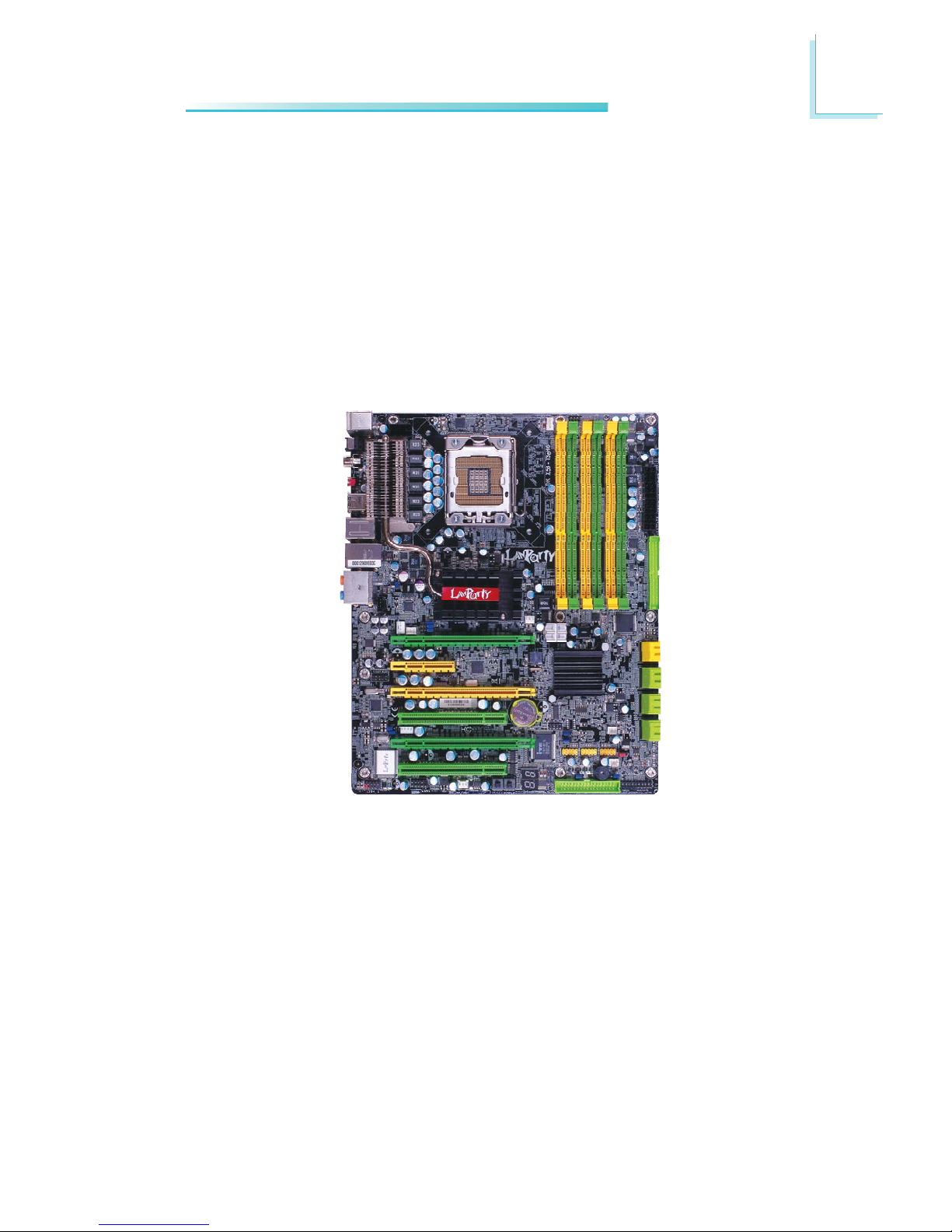
Chapter 2 - Hardware Installation
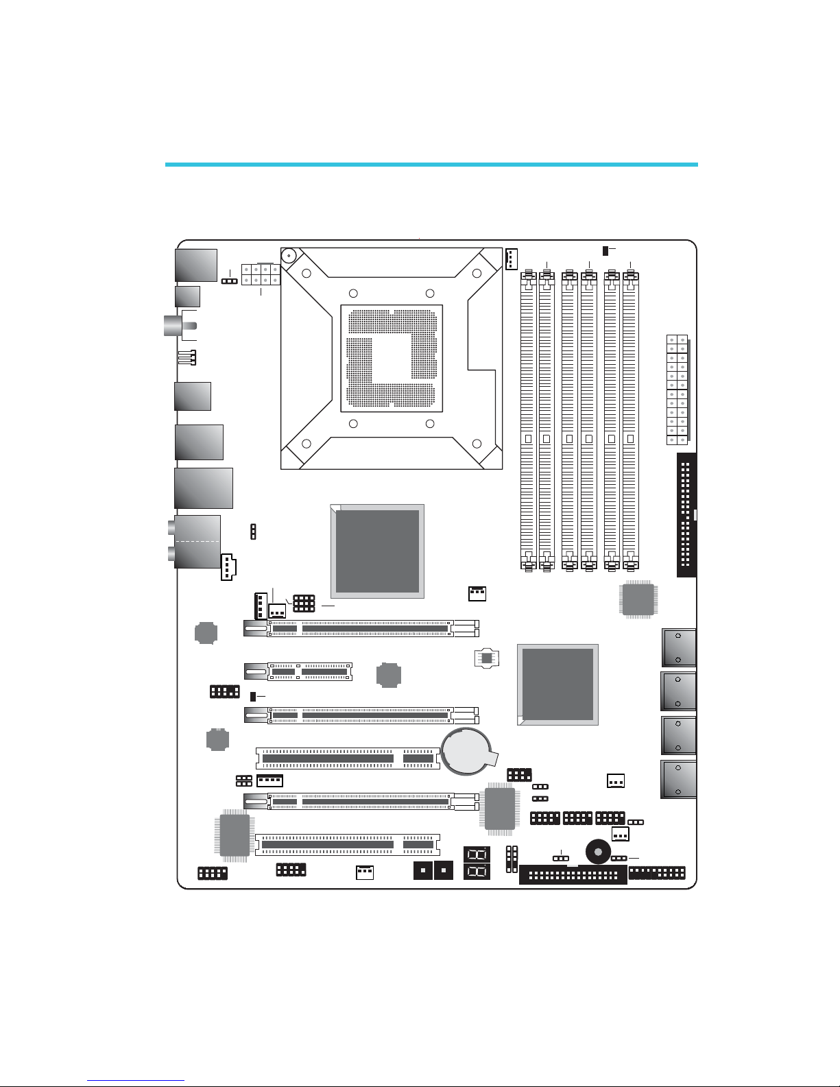
System Board Layout
Front panel
1
Reset Power
SATA 5
SATA 6
SATA 3
SATA 4
SATA 1
SATA 2
SATA 7
SATA 8
1 1
IrDA
CIR
1
1394-1
1
System
fan
1
1
1
1
1
1
Fan 2
1
Fan 1
PCIE 2
NB fan
5V/12V
1
power
PCI 2
1
1
1
CPU fan
1
JP15
J13P
JP14
1
12V power
Mouse
KB
2412
1
13
ATX
power
1
IDE
1
1
Intel
X58
Battery
JMicron
JMB363
LGA 1366
USB 2-3
Clear CMOS
(J )P2
Intel
ICH10R
1
1
1
1
Speaker On/Off
(J )P8
Safe boot (J )P1
Secondary RTC
Reset (J )P12
PCIE 1
PCIE 3
PCIE 4
1
1
DIMM 1
DIMM 2 DIMM 4
DIMM 3
DIMM 6
DIMM 5
Fan 3
SPI Flash
BIOS
PS/2 power
select
(J )P7
DRAM Power LED
USB 6-11
select (JP5)
power
Realtek
ALC889
Marvell
88E8053
PCI 1
JP26
JP27
1
CPU FSB select
(JP13-JP15)
5V/12V
power
ITE
IT8718F
VIA
VT6308P
COM
1
1
USB 0-5 power
select (JP6)
USB 4-5 USB 0-1
1
2
7
8
Download
Flash BIOS
CPU_VTT select
(JP26-JP27)
Standby
Power LED
1
LAN
USB 10-11
Line-in
Front R/L
Mic-in
Center/
Subwoofer
Side R/L
Rear R/L
USB 6-7
Optical
S/PDIF-out
1
Coaxial RCA
S/PDIF-out
Clear CMOS
(JP10)
1394-0
USB 8-9
1
CD-in
Front audio
1
FDD
16
2
Hardware Installation
1
Warning:
Electrostatic discharge (ESD) can damage your system board, processor, disk drives, add-in boards, and other components. Perform the
upgrade instruction procedures described at an ESD workstation only.
If such a station is not available, you can provide some ESD protection by wearing an antistatic wrist strap and attaching it to a metal
part of the system chassis. If a wrist strap is unavailable, establish
and maintain contact with the system chassis throughout any procedures requiring ESD protection.
System Memory
Warning:
When the DRAM Power LED lit red, it indicates that power is
present on the DIMM sockets. Power-off the PC then unplug the
power cord prior to installing any memory modules. Failure to do so
will cause severe damage to the motherboard and components.
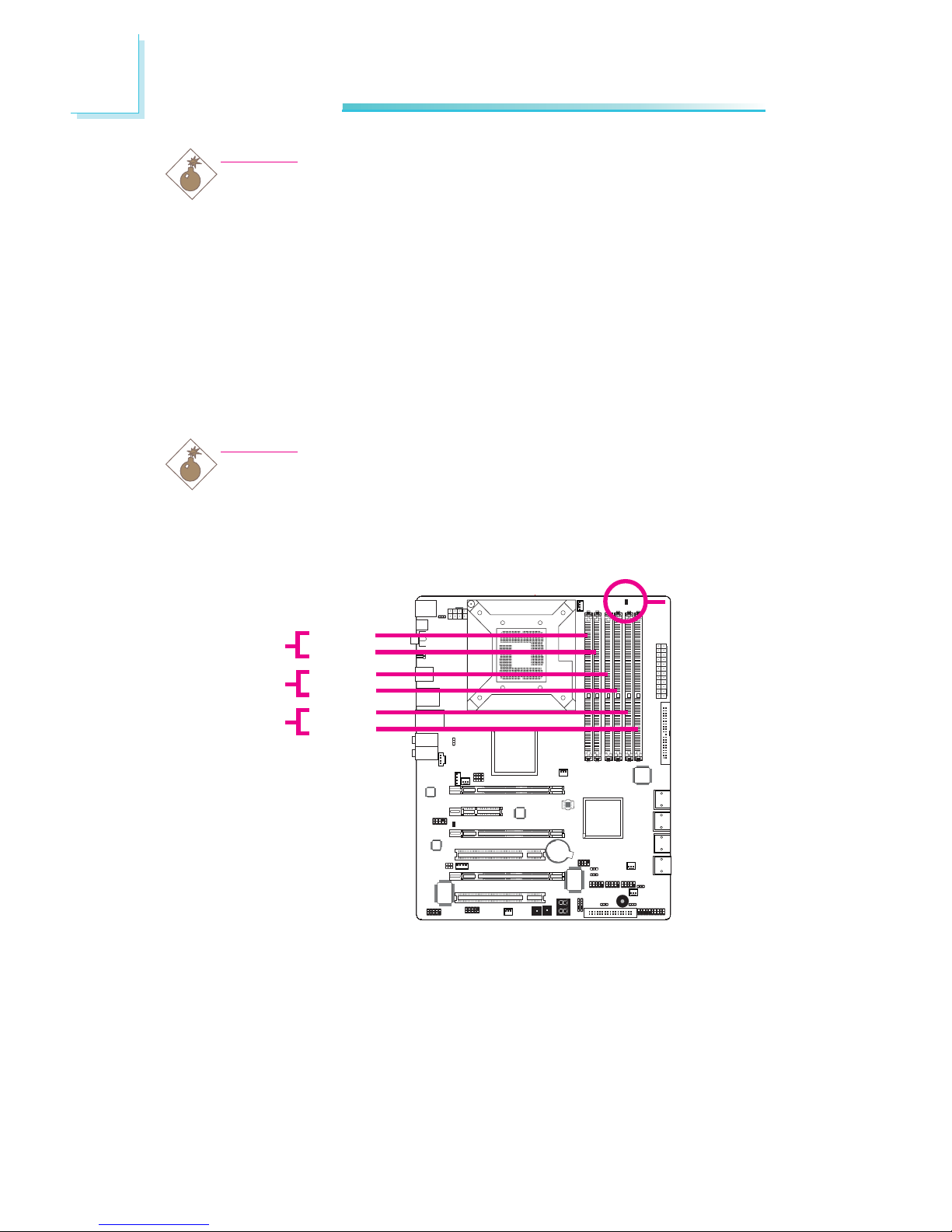
The 6 DIMM sockets on the system board are divided into 3
channels:
Channel A - DIMM 1 and DIMM 2
Channel B - DIMM 3 and DIMM 4
Channel C - DIMM 5 and DIMM 6
.
.
.
.
.
.
.
.
.
.
.
.
.
.
.
.
DIMM 1
DIMM 2
Channel A
Channel B
DRAM
Power LED
DIMM 3
DIMM 4
Channel C
DIMM 5
DIMM 6

17
2
Hardware Installation
Memory Configuration
1 module
1 module
1 module
DIMM2
-
-
-
Single Channel
DIMM1
DS/SS
-
-
DIMM4
-
-
-
DIMM3
-
DS/SS
-
DIMM6
-
-
-
DIMM5
-
-
DS/SS
“SS” denotes single-sided DIMM
“DS” denotes double-sided DIMM
“-” denotes no DIMM
Note:
DO NOT populate DIMM2, DIMM4 and DIMM6. The system will not
boot when DIMM is installed in one of these sockets.
Channel A
Channel B Channel C
2 modules
4 modules
DIMM2
-
DS/SS
Dual Channel
DIMM1
DS/SS
DS/SS
DIMM4
-
DS/SS
DIMM3
DS/SS
DS/SS
DIMM6
-
-
DIMM5
-
-
“SS” denotes single-sided DIMM
“DS” denotes double-sided DIMM
“-” denotes no DIMM
Note:
When installing 2 modules, install in DIMM1 and DIMM3 or DIMM3
and DIMM5. The system will not boot when a module is installed in
DIMM2, DIMM4 or DIMM6.
Channel A
Channel B Channel C
3 modules
4 modules
6 modules
DIMM2
-
DS/SS
DS/SS
Triple Channel
DIMM1
DS/SS
DS/SS
DS/SS
DIMM4
-
-
DS/SS
DIMM3
DS/SS
DS/SS
DS/SS
DIMM6
-
-
DS/SS
DIMM5
DS/SS
DS/SS
DS/SS
“SS” denotes single-sided DIMM
“DS” denotes double-sided DIMM
“-” denotes no DIMM
Note:
• When installing 3 modules, install in DIMM1, DIMM3 and DIMM5.
The system will not boot when a module is installed in DIMM2,
DIMM4 or DIMM6.
• When 4 memor y modules of different capacities and chips are
installed, the system memory is able to operate in triple “Intel Flex
Memory Mode” and works in 2N mode.
Channel A
Channel B Channel C
18
2
Hardware Installation
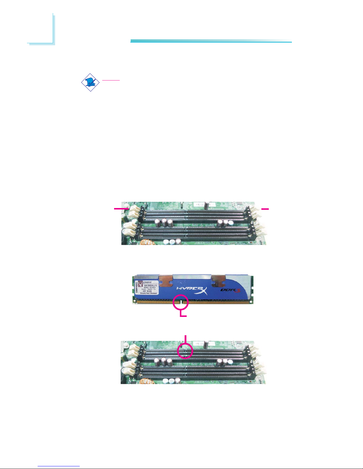
Installing the DIM Module
Note:
The system board used in the following illustrations may not
resemble the actual board. These illustrations are for reference
only.
1. Make sure the PC and all other peripheral devices connected to
it has been powered down.
2. Disconnect all power cords and cables.
3. Locate the DIMM socket on the system board.
4. Push the “ejector tabs” which are at the ends of the socket to
the side.
Ejector
tab
5. Note how the module is keyed to the socket.
Ejector
tab
Key
Notch
19
2
Hardware Installation
BIOS Setting
Configure the system memory in the Genie BIOS Setting submenu
of the BIOS. Refer to chapter 3 for more information.
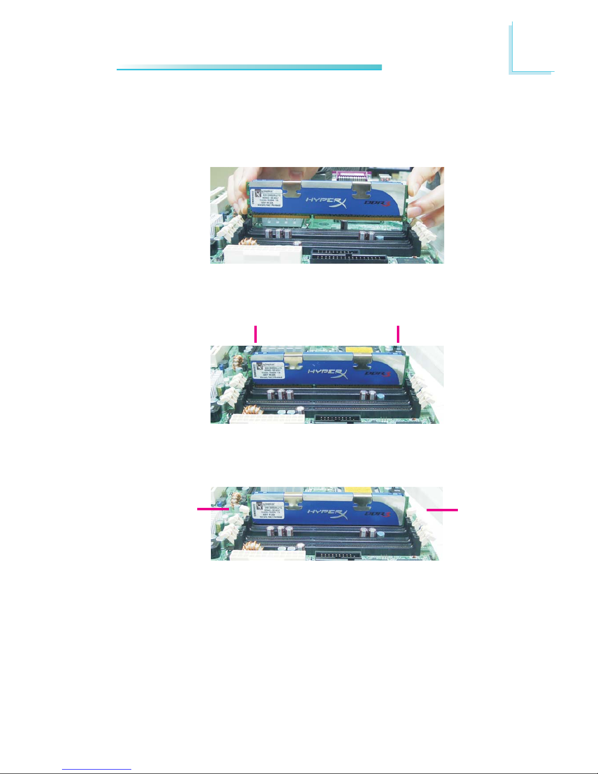
7. Seat the module vertically, pressing it down firmly until it is completely seated in the socket.
6. Grasping the module by its edges, position the module above
the socket with the “notch” in the module aligned with the “key”
on the socket. The keying mechanism ensures the module can be
plugged into the socket in only one way.
8. The ejector tabs at the ends of the socket will automatically
snap into the locked position to hold the module in place.
X
X
X
X

20
2
Hardware Installation
CPU
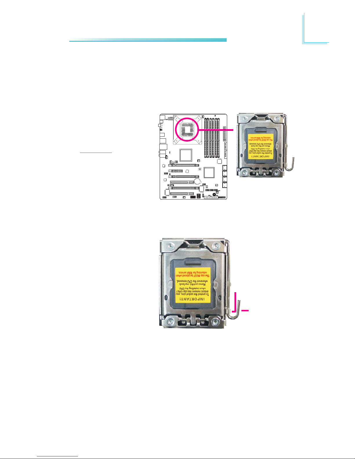
Overview
The system board is equipped with a surface mount LGA 1366 socket.
This socket is exclusively designed for Intel® CoreTM i7 CPU.
Important:
1. Before you proceed, make sure (1) the LGA 13661. Before you proceed, make sure (1) the LGA 1366
1. Before you proceed, make sure (1) the LGA 13661. Before you proceed, make sure (1) the LGA 1366
1. Before you proceed, make sure (1) the LGA 1366
socket comes with a protective cap, (2) the cap is notsocket comes with a protective cap, (2) the cap is not
socket comes with a protective cap, (2) the cap is notsocket comes with a protective cap, (2) the cap is not
socket comes with a protective cap, (2) the cap is not
damaged and (3) the socket contacts are not bent. Ifdamaged and (3) the socket contacts are not bent. If
damaged and (3) the socket contacts are not bent. Ifdamaged and (3) the socket contacts are not bent. If
damaged and (3) the socket contacts are not bent. If
the cap is missing or the cap and/or contacts arethe cap is missing or the cap and/or contacts are
the cap is missing or the cap and/or contacts arethe cap is missing or the cap and/or contacts are
the cap is missing or the cap and/or contacts are
damaged,damaged,
damaged,damaged,
damaged,
contact your dealer immediately contact your dealer immediately
contact your dealer immediately contact your dealer immediately
contact your dealer immediately
..
..
.
2. Make sure to keep the protective cap. RMA requests2. Make sure to keep the protective cap. RMA requests
2. Make sure to keep the protective cap. RMA requests2. Make sure to keep the protective cap. RMA requests
2. Make sure to keep the protective cap. RMA requests
will be accepted and processed only if the LGA 1366will be accepted and processed only if the LGA 1366
will be accepted and processed only if the LGA 1366will be accepted and processed only if the LGA 1366
will be accepted and processed only if the LGA 1366
socket comes with the protective cap.socket comes with the protective cap.
socket comes with the protective cap.socket comes with the protective cap.
socket comes with the protective cap.
X
Protective cap
21
2
Hardware Installation
1
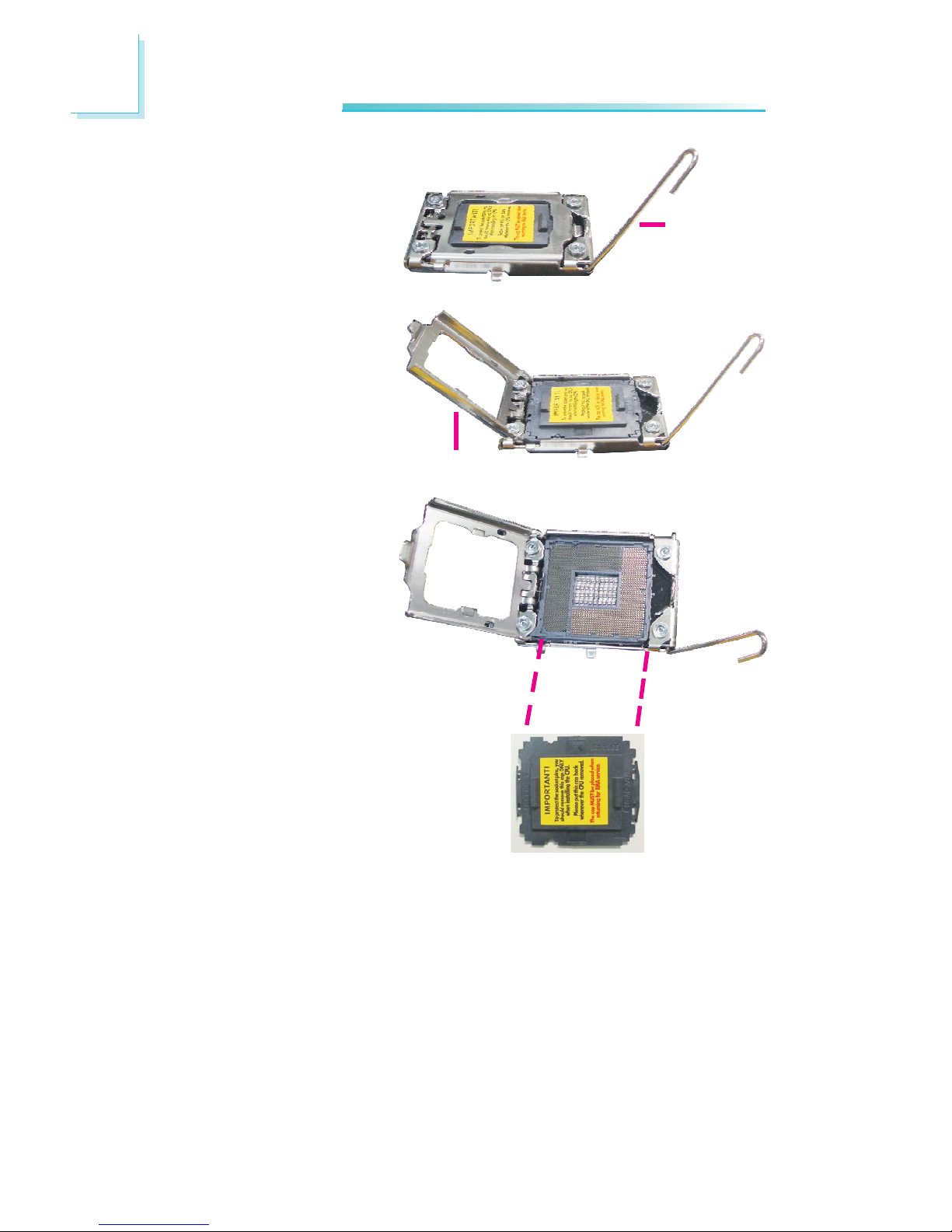
4. Unlock the socket by
pushing the load lever
down, moving it
sideways until it is
released from the
retention tab.
Installing the CPU
1. Make sure the PC and all other peripheral devices connected to it has
been powered down.
2. Disconnect all power cords and cables.
3. Locate the LGA 1366
CPU socket on the
system board.
Important:
The CPU socket must
not come in contact with
anything other than the
CPU. Avoid unnecessary
exposure. Remove the
protective cap only when
you are about to install
the CPU.
Load lever
Retention
tab
22
2
Hardware Installation
5. Lift the load lever.
6. Lift the load plate.
Load lever
Load plate
7. Remove the protective
cap from the CPU
socket. The cap is used
to protect the CPU
socket against dust and
harmful particles. Remove the protective cap
only when you are about
to install the CPU.
23
2
Hardware Installation
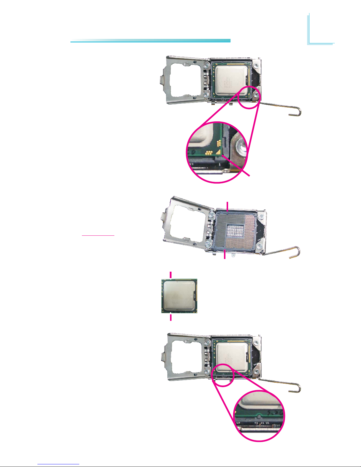
8. Insert the CPU into the
socket. The gold
triangular mark on the
CPU must align with the
corner of the CPU
socket shown on the
right photo.
Gold triangular
mark
The CPU’s notch will at
the same time fit into
the socket alignment key.
Important:
The CPU will fit in only
one orientation and can
easily be inserted
without exerting any
force.
Alignment key
Alignment key
CPU notch
CPU notch
24
2
Hardware Installation
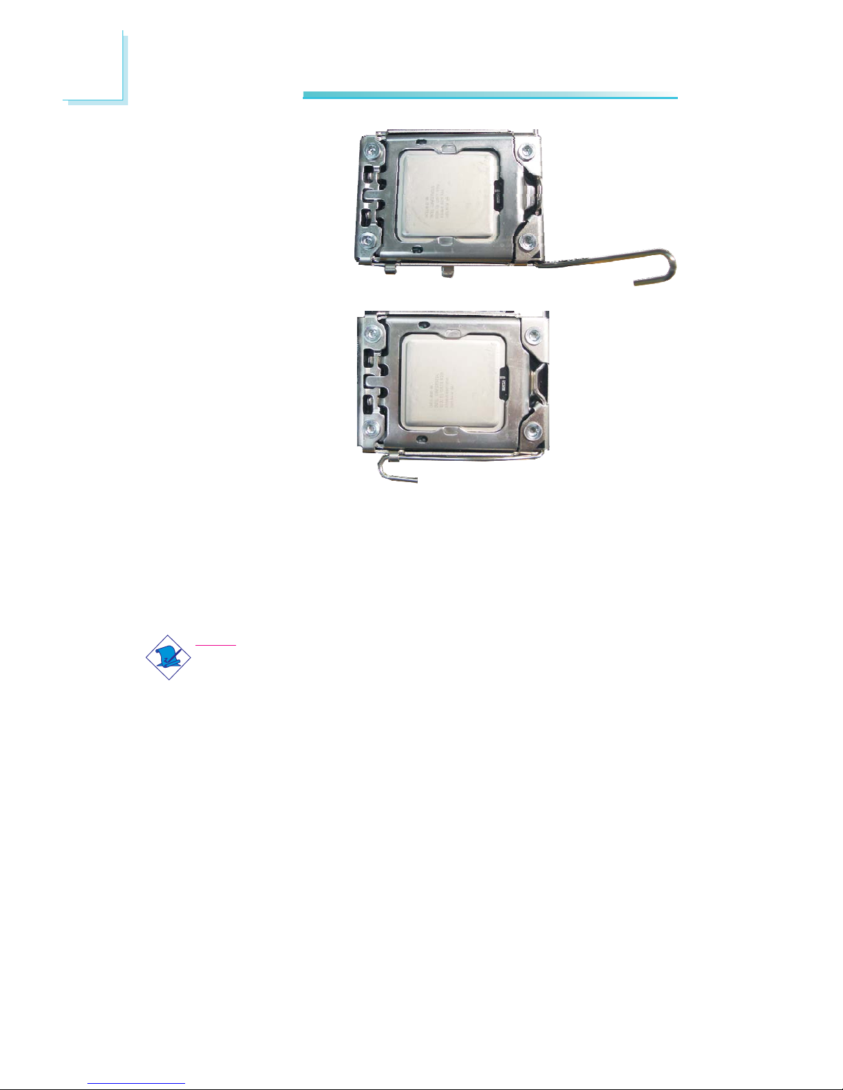
9. Close the load plate.
10. Push the load lever
down to lock the socket.
The lever should hook
onto the retention tab
to indicate that the CPU
is completely secured in
the socket.
Installing the Fan and Heat Sink
The CPU must be kept cool by using a CPU fan with heat sink. Without
sufficient air circulation across the CPU and heat sink, the CPU will
overheat damaging both the CPU and system board.
Note:
A boxed Intel® processor already includes the CPU fan and heat sink
assembly. If your CPU was purchased separately, make sure to use
only Intel®-certified fan and heat sink.
1. Before you install the fan / heat sink, you must apply a thermal paste
onto the top of the CPU. The thermal paste is usually supplied when
you purchase the fan / heat sink assembly. Do not spread the paste all
over the surface. When you later place the heat sink on top of the
CPU, the compound will disperse evenly.
Some heat sinks come with a patch of pre-applied thermal paste. Do
not apply thermal paste if the fan / heat sink already has a patch of
thermal paste on its underside. Peel the strip that covers the paste
before you place the fan / heat sink on top of the CPU.
25
2
Hardware Installation
1
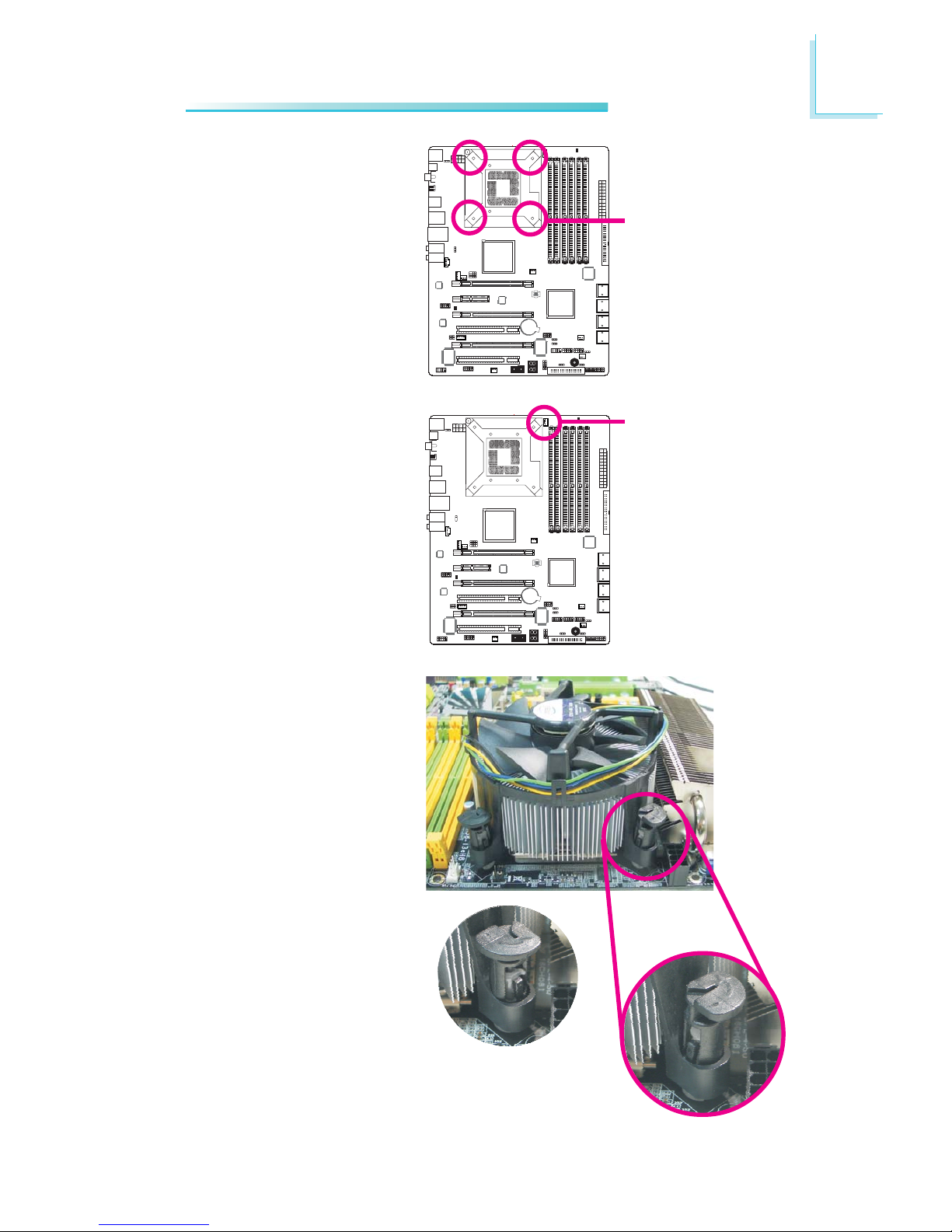
2. Place the heat sink on
top of the CPU. The 4
push-pins around the
heat sink, which are used
to secure the heat sink
onto the system board,
must match the 4
mounting holes around
the socket.
Mounting hole
4. Rotate each push-pin
according to the
direction of the arrow
shown on top of the
pin.
Push down two pushpins that are diagonally
across the heat sink..
Perform the same
procedure for the other
two push-pins.
“Unlocked”
position of
push-pin
“Locked” position
of push-pin
3. Orient the heat sink
such that the CPU fan’s
cable is closest the CPU
fan connector.
1
CPU fan
connector
26
2
Hardware Installation
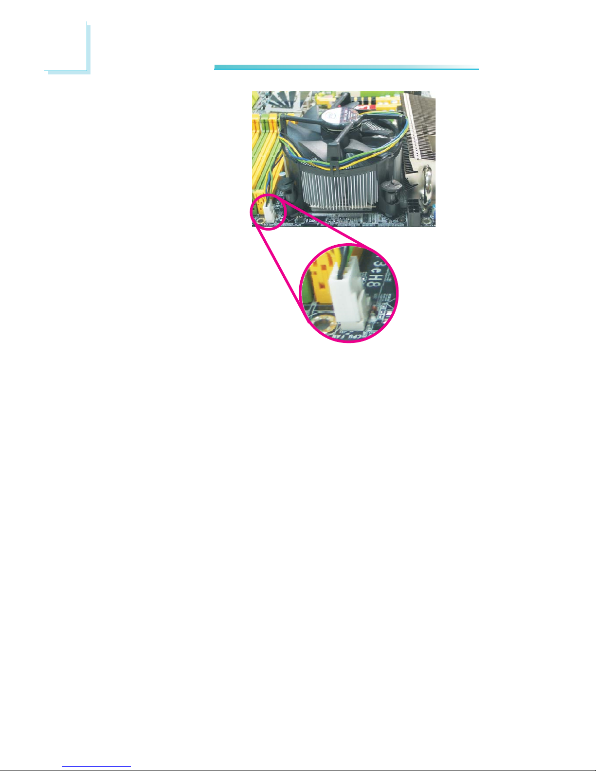
5. Connect the CPU fan’s
cable connector to the
CPU fan connector on
the system board.
27
2
Hardware Installation
Northbridge Heat Sink
The Northbridge must be kept cool by using a heat sink. The heat
sink will dissipate heat generated by the Northbridge. Without the
heat sink, the Northbridge will overheat damaging both the
Northbridge and the system board.
The system board comes with the heat sink already installed on the
board. The copper-made heat pipe technology provides excellent
heat dissipation.
28
2
Hardware Installation
1
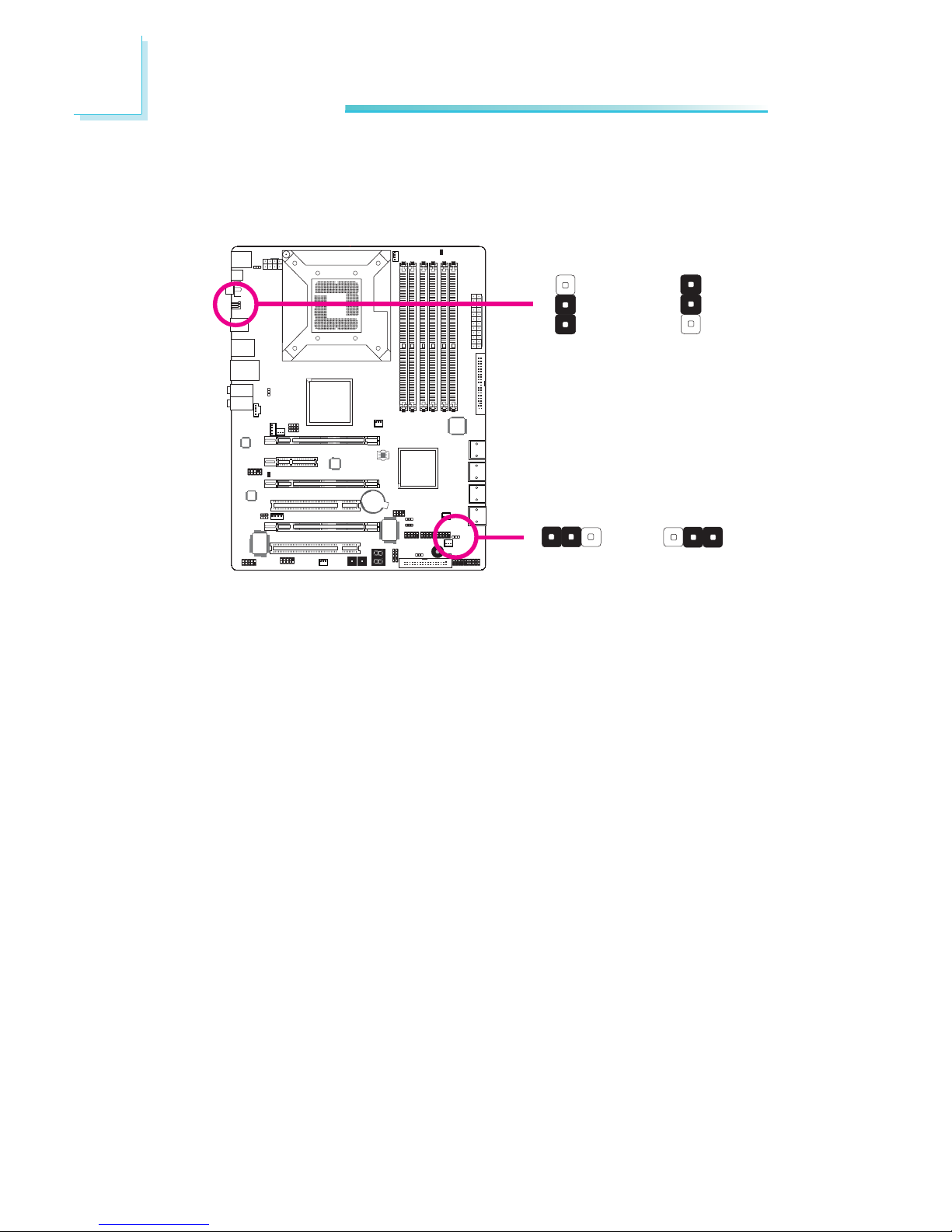
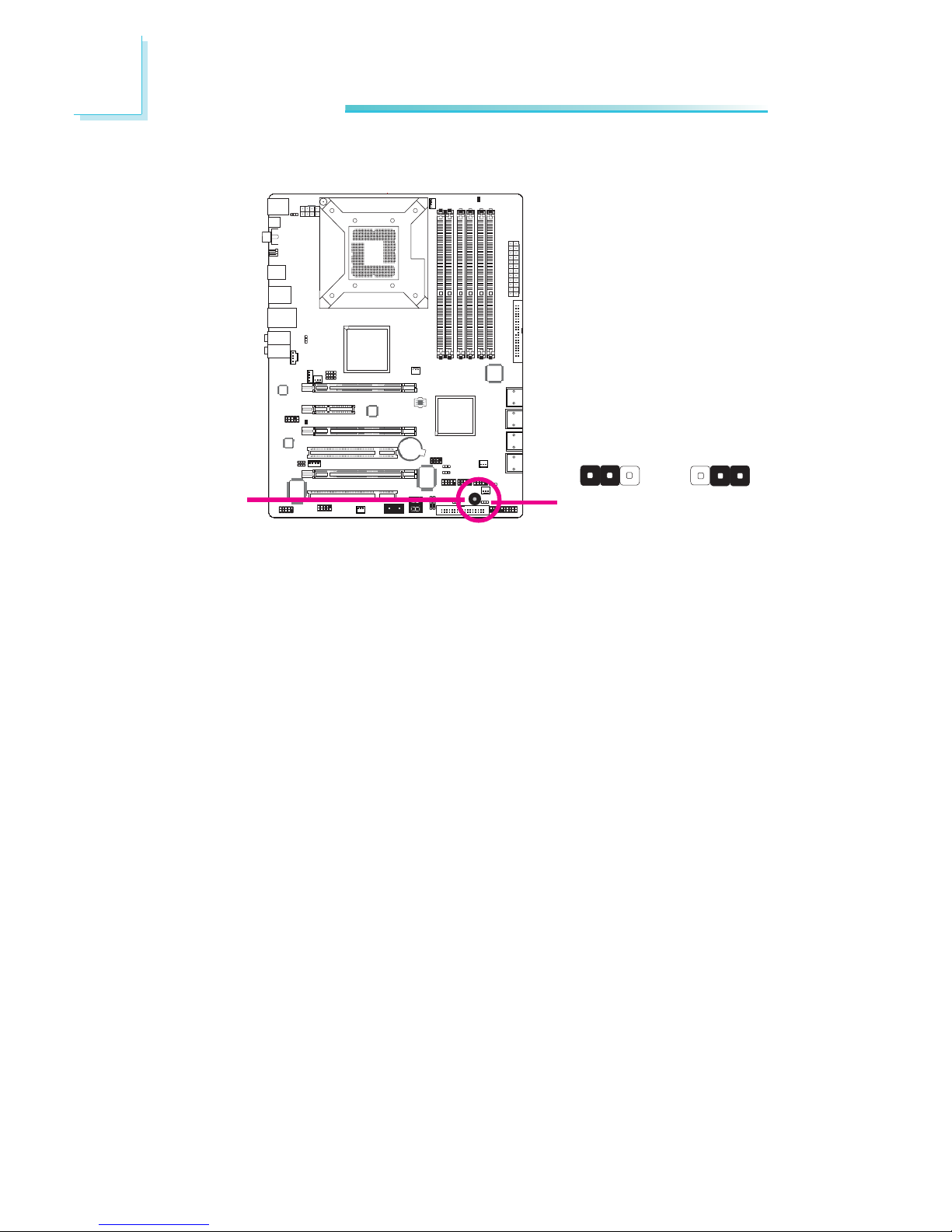
Jumper Settings
Clear CMOS Data
2-3 On:
Clear CMOS Data
1-2 On: Normal
(default)
X
JP2
312 312
JP10
X
2-3 On:
Clear CMOS Data
1-2 On: Normal
(default)
1
3
2
1
3
2
If you encounter the following,
a) CMOS data becomes corrupted.
b) You forgot the supervisor or user password.
c) The overclocked settings in the BIOS resulted to the system’s in-
stability or caused system boot up problems.
you can reconfigure the system with the default values stored in the
ROM BIOS.
JP10 is accessible from the rear panel of the system. This provides
convenience by allowing you to clear the CMOS without having to
remove the chassis cover.
To load the default values stored in the ROM BIOS, please follow
the steps below.
1. Power-off the system then unplug the power cord.
2. Set JP2 or JP10 pins 2 and 3 to On. Wait for a few seconds
and set JP2 or JP10 back to its default setting, pins 1 and 2 On.
3. Now plug the power cord then power-on the system.
29
2
Hardware Installation
1
1
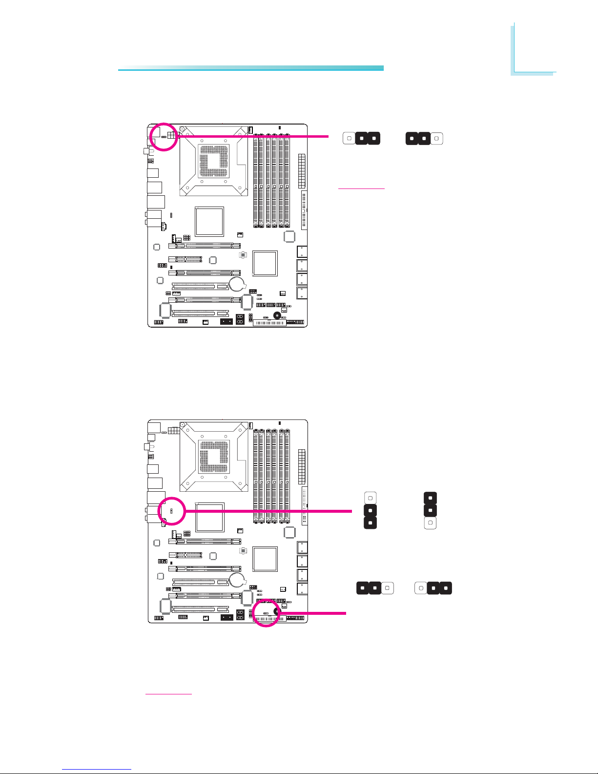
PS/2 Power Select
Selecting 5VSB will allow you to use the PS/2 keyboard or PS/2
mouse to wake up the system.
X
JP7
2-3 On:
5VSB
1-2 On: 5V
(default)
31
2
312
USB Power Select
X
USB 6-11
(JP5)
X
USB 0-5
(JP6)
2-3 On:
5VSB
1-2 On: 5V
(default)
1
3
2
1
3
2
2-3 On:
5VSB
1-2 On: 5V
(default)
Selecting 5VSB will allow you to use the USB keyboard or USB
mouse to wake up the system..
Important:
The 5VSB power source of your
power supply must support
≥720mA.
Important:
The 5VSB power source of your power supply must support ≥1.5A (2 devices)
or ≥2A (3 or more devices).
312 312
30
2
Hardware Installation
1
The system board is equipped with a buzzer which serves as the
PC’s speaker. By default the buzzer is “on” allowing you to hear the
system’s beep messages and warnings. If you intend to use an external speaker, turn this function off by setting JP8 pins 1 and 2 to On.
Speaker On/Off Select
JP8
2-3 On:
Speaker On
(default)
1-2 On:
Speaker Off
Buzzer
312 312
X
 Loading...