


LANPARTY X48 User Guide

System Board
User’s Manual

Copyright
This publication contains information that is protected by copyright.
No part of it may be reproduced in any form or by any means or
used to make any transformation/adaptation without the prior written permission from the copyright holders.
This publication is provided for informational purposes only. The
manufacturer makes no representations or warranties with respect to
the contents or use of this manual and specifically disclaims any express or implied warranties of merchantability or fitness for any particular purpose. The user will assume the entire risk of the use or the
results of the use of this document. Further, the manufacturer reserves the right to revise this publication and make changes to its
contents at any time, without obligation to notify any person or entity of such revisions or changes.
© 2008. All Rights Reserved.
Trademarks
Windows® 98, Windows® 98 SE, Windows® ME, Windows® 2000,
Windows NT® 4.0 and Windows® XP are registered trademarks of
Microsoft Corporation. VIA is a registered trademark of VIA Technologies, Inc. Award is a registered trademark of Award Software,
Inc. Other trademarks and registered trademarks of products appearing in this manual are the properties of their respective holders.

FCC and DOC Statement on Class B
This equipment has been tested and found to comply with the limits
for a Class B digital device, pursuant to Part 15 of the FCC rules.
These limits are designed to provide reasonable protection against
harmful interference when the equipment is operated in a residential
installation. This equipment generates, uses and can radiate radio frequency energy and, if not installed and used in accordance with the
instruction manual, may cause harmful interference to radio communications. However, there is no guarantee that interference will not
occur in a particular installation. If this equipment does cause harmful
interference to radio or television reception, which can be determined
by turning the equipment off and on, the user is encouraged to try
to correct the interference by one or more of the following measures:
• Reorient or relocate the receiving antenna.
• Increase the separation between the equipment and the receiver.
• Connect the equipment into an outlet on a circuit different from
that to which the receiver is connected.
• Consult the dealer or an experienced radio TV technician for
help.
Notice:
1. The changes or modifications not expressly approved by the
party responsible for compliance could void the user's authority
to operate the equipment.
2. Shielded interface cables must be used in order to comply with
the emission limits.

Table of Contents
Warranty.................................................................................................
Static Electricity Precaution................................................................
Safety Measures.....................................................................................
About the Package...............................................................................
Before Using the System Board.........................................................
Chapter 1 - Introduction....................................................................
Specifications...................................................................................................................................
Features..............................................................................................................................................
Chapter 2 - Hardware Installation....................................................
System Board Layout ..........................................................................................................
System Memory..........................................................................................................................
CPU.......................................................................................................................................................
Flame-Freezer Heat Sink....................................................................................................
Jumper Settings............................................................................................................................
Rear Panel I/O Ports.............................................................................................................
Bernstein Audio Module......................................................................................................
Internal I/O Connectors.....................................................................................................
5
6
6
7
7
8
8
10
16
16
17
23
28
34
41
43
45
Chapter 3 - BIOS Setup......................................................................
Award BIOS Setup Utility.................................................................................................
RAID BIOS.....................................................................................................................................
Updating the BIOS..................................................................................................................
Chapter 4 - Supported Software.......................................................
Chapter 5 - RAID.................................................................................
Chapter 6 - ATI CrossFire Technology.............................................
Appendix A - System Error Message...............................................
Appendix B - Troubleshooting..........................................................
56
56
99
100
102
120
127
136
138

Warranty
1. Warranty does not cover damages or failures that arised from
misuse of the product, inability to use the product, unauthorized
replacement or alteration of components and product specifications.
2. The warranty is void if the product has been subjected to physical abuse, improper installation, modification, accidents or unauthorized repair of the product.
3. Unless otherwise instructed in this user’s manual, the user may
not, under any circumstances, attempt to perform service, adjustments or repairs on the product, whether in or out of warranty.
It must be returned to the purchase point, factory or authorized
service agency for all such work.
4. We will not be liable for any indirect, special, incidental or
consequencial damages to the product that has been modified
or altered.

1
Introduction
Static Electricity Precautions
It is quite easy to inadvertently damage your PC, system board,
components or devices even before installing them in your system
unit. Static electrical discharge can damage computer components
without causing any signs of physical damage. You must take extra
care in handling them to ensure against electrostatic build-up.
1. To prevent electrostatic build-up, leave the system board in its
anti-static bag until you are ready to install it.
2. Wear an antistatic wrist strap.
3. Do all preparation work on a static-free surface.
4. Hold the device only by its edges. Be careful not to touch any of
the components, contacts or connections.
5. Avoid touching the pins or contacts on all modules and connectors. Hold modules or connectors by their ends.
Important:
Electrostatic discharge (ESD) can damage your processor, disk
drive and other components. Perform the upgrade instruction
procedures described at an ESD workstation only. If such a
station is not available, you can provide some ESD protection
by wearing an antistatic wrist strap and attaching it to a metal
part of the system chassis. If a wrist strap is unavailable, establish and maintain contact with the system chassis throughout
any procedures requiring ESD protection.
Safety Measures
To avoid damage to the system:
• Use the correct AC input voltage range
To reduce the risk of electric shock:
• Unplug the power cord before removing the system chassis
cover for installation or servicing. After installation or servicing,
cover the system chassis before plugging the power cord.
..
.
..
Battery:
• Danger of explosion if battery incorrectly replaced.
• Replace only with the same or equivalent type recommend
the manufacturer.
• Dispose of used batteries according to local ordinance.
by
6

About the Package
The system board package contains the following items. If any of
these items are missing or damaged, please contact your dealer or
sales representative for assistance.
; One system board
; One Bernstein audio module with cable
; One Flame-Freezer heat sink kit
; One IDE round cable
; One floppy round cable
; Four Serial ATA data cables
; Four Serial ATA power cables
; One I/O shield
; One RAID driver diskette
; One “Mainboard Utility” CD
; One user’s manual
Introduction
1
The system board and accessories in the package may not come
similar to the information listed above. This may differ in accordance
to the sales region or models in which it was sold. For more information about the standard package in your region, please contact
your dealer or sales representative.
Before Using the System Board
Before using the system board, prepare basic system components.
If you are installing the system board in a new system, you will need
at least the following internal components.
• A CPU
• Memory module
• Storage devices such as hard disk drive, CD-ROM, etc.
You will also need external system peripherals you intend to use
which will normally include at least a keyboard, a mouse and a video
display monitor.
7

1
Introduction
Chapter 1 - Introduction
Specifications
Processor
Chipset
System Memory
Expansion Slots
• LGA 775 socket for:
- Intel® CoreTM2 Quad and Intel® CoreTM2 Duo
• Supports Intel Enhanced Memory 64 Technology (EMT64T)
• Supports Enhanced Intel SpeedStep Technology (EIST)
• Supports Intel Hyper-Threading Technology
• Supports 1600/1333/1066/800MHz FSB
®
• Intel
• Four 240-pin DDR2 DIMM sockets
• Supports DDR2 667/800 MHz
• Delivers up to 12.8Gb/s bandwidth
• Supports dual channel (128-bit wide) memory interface
• Supports up to 8GB system memory
• Supports unbuffered x8 and x16 DIMMs
• 2 PCI Express (Gen 2) x16 slots (PCIE 1 and PCIE 3)
• 1 PCI Express x1 slot (PCIE 2)
• 1 PCI Express x4 slot (PCIE 4)
• 3 PCI slots
chipset
- Northbridge:
Intel® X48 Express chipset
Intel® Fast Memory Access technology
- Southbridge: Intel® ICH9R
- 2-way CrossFire at x16/x16 bandwidth
- 2-way CrossFire + Physics at x16/x16/x4 bandwidth
BIOS
Audio
LAN
• Award BIOS
• 8Mbit flash memory
• CMOS Reloaded
• Bernstein audio module
- Realtek ALC885 8-channel High Definition Audio CODEC
- Center/subwoofer, rear R/L and side R/L jacks
- Line-in, line-out (front R/L) and mic-in jacks
- 2 coaxial RCA S/PDIF-in/out jacks
- 1 optical S/PDIF connector
- 1 CD-in connector
- 1 front audio connector
• DAC SNR/ADC SNR of 106dB/101dB
• Full-rate lossless content protection technology
• Marvell 88E8052 and Marvell 88E8053 PCIE Gigabit LAN
controllers
• Fully compliant to IEEE 802.3 (10BASE-T), 802.3u (100BASETX) and 802.3ab (1000BASE-T) standards
8

Introduction
1
Storage
IEEE 1394
Rear Panel I/O
Internal I/O
• Intel ICH9R chip
- Intel Matrix Storage technology
- Supports up to 6 SATA devices
- SATA speed up to 3Gb/s
- RAID 0, RAID 1, RAID 0+1 and RAID 5
• JMicron JMB363 PCI Express to SATA and PATA host controller
- Supports up to 2 UltraDMA 100Mbps IDE devices
- Supports 2 SATA devices
- SATA speed up to 3Gb/s
- RAID 0 and RAID 1
• VIA VT6307
• Supports two 100/200/400 Mb/sec ports
• Mini-DIN-6 PS/2 mouse port and PS/2 keyboard port
• 1 IEEE 1394 port
• 6 USB 2.0/1.1 ports
• 2 RJ45 LAN ports
• 3 connectors for 6 additional external USB 2.0 ports
• 1 connector for an external COM por t
• 1 connector for an IEEE 1394 port
• 1 connector for the Bernstein audio module
• 1 front audio connector (on the Bernstein audio module)
• 1 CD-in connector (on the Bernstein audio module)
• 1 S/PDIF connector (on the Bernstein audio module)
• 1 IrDA connector
• 1 CIR connector
• 8 Serial ATA connectors
• 1 40-pin IDE connector
• 1 floppy connector
• 1 24-pin ATX power connector
• 1 8-pin 12V power connector
• 2 4-pin 5V/12V power connectors (FDD type)
• 1 front panel connector
• 6 fan connectors
• 1 diagnostic LED
• EZ touch switches (power switch and reset switch)
Power Management
Hardware Monitor
PCB
• ACPI and OS Directed Power Management
• ACPI STR (Suspend to RAM) function
• Wake-On-PS/2 / Wake-On-USB Keyboard/Mouse
• Wake-On-LAN and Wake-On-Ring
• RTC timer to power-on the system
• AC power failure recovery
• Monitors CPU/system/Northbridge temperature and overheat alarm
• Monitors Vcore/Vdimm/Vnb/VCC5/12V/V5sb/Vbat voltages
• Monitors the speed of the cooling fans
• CPU Overheat Protection function monitors CPU temperature
and fan during system boot-up - automatic shutdown upon system overheat
• 6 layers, ATX form factor
• 24.5cm (9.64") x 30.5cm (12")
9

1
Introduction
Features
The data transfer rate of the high performance DDR2
technology delivers bandwidth of 12.8 Gb/s and beyond.
That is twice the speed of the conventional DDR with-
out increasing its power consumption. DDR2 SDRAM
modules work at 1.8V supply compared to 2.6V memory voltage
for DDR modules. DDR2 also incorporates new innovations such as
the On-Die Termination (ODT) as well as larger 4-bit pre-fetch
against DDR which fetches 2 bits per clock cycle.
ATI’s CrossFire
PC to a new peak of performance by
combining multiple GPUs in a single system. By connecting a Radeon CrossFire Edition graphics card and a
standard PCI Express graphics card, the power of the dual GPUs
(Graphics Processing Units) within the system will accelerate your
gaming performance and improve image quality.
Aside from dual GPU for 3D rendering, CrossFire’s new feature asymmetric processing technology, allows adding another dedicated
GPU for physics processing. The 3 GPUs simultaneously handle Data
Parallel Processing (DPP) computing tasks such as game rendering
and physics in a single system. This provides more realistic cutting
edge 3D graphics to run at high resolutions.
The Realtek ALC885 on the Bernstein audio module
supports 6 audio jacks that provide 8-channel audio
output for advanced 7.1-channel super surround sound
audio system. It is also equipped with a CD-in connector,
front audio connector and S/PDIF output allowing digital connections
with DVD systems or other audio/video multimedia.
TM
technology drives your
10
Introduction
S/PDIF is a standard audio file transfer format that
transfers digital audio signals to a device without having
to be converted first to an analog format. This prevents
the quality of the audio signal from degrading whenever
it is converted to analog. S/PDIF is usually found oyn digital audio
equipment such as a DAT machine or audio processing device. The
S/PDIF interface on the system board sends surround sound and
3D audio signal outputs to amplifiers and speakers and to digital
recording devices like CD recorders.
1
JMB363JMB363
JMB363
JMB363JMB363
ATA devices.
and JMicron JMB363 both support speed of up to 3Gb/s. Serial
ATA improves hard drive performance faster than the standard parallel ATA whose data transfer rate is 100MB/s.
The JMicron JMB363 controller supports up to two
UltraDMA 100Mbps IDE devices and two Serial
Serial ATA is a storage interface that is compliant with SATA 1.0 specification. Intel ICH9R
The Intel ICH9R chip allows configuring RAID on Serial ATA
devices. It supports RAID 0, RAID 1, RAID 0+1 and RAID
5.
The JMicron JMB363 chip allows configuring RAID on another 2 Serial ATA devices. It suppor ts RAID 0 and RAID
1.
The Marvell 88E8052 and Marvell 88E8053 PCI Express
Gigabit LAN controllers suppor t up to 1Gbps data rate.
11
1
Introduction
IEEE 1394 is fully compliant with the 1394 OHCI (Open
Host Controller Interface) 1.1 specification. It supports up
to 63 devices that can run simultaneously on a system.
1394 is a fast external bus standard that supports data
transfer rates of up to 400Mbps. In addition to its high speed, it
also supports isochronous data transfer which is ideal for video devices that need to transfer high levels of data in real-time. 1394
supports both Plug-and-Play and hot plugging.
CMOS Reloaded is a technology that allows storing
multiple user-defined BIOS settings by using the
BIOS utility to save, load and name the settings. This
is especially useful to overclockers who require saving a variety of overclocked settings and being able
to conveniently switch between these settings simultaneously.
hyper-threading
technology
Technology for your computer system requires ALL of the following
platforms.
Components:
• CPU - an Intel
• Chipset - an Intel® chipset that supports HT Technology
• BIOS - a BIOS that supports HT Technology and has it enabled
• OS - an operating system that includes optimizations for HT
Technology
For more information on Hyper-Threading Technology, go to:
www.intel.com/info/hyperthreading.
the physical layer of x1 and x16 lane widths. The x1 PCI Express
lane supports transfer rate of 2.5 Gigabytes (250MBbps) per second. The PCI Express architecture also provides a high performance
graphics infrastructure by enhancing the capability of a x16 PCI Express lane to provide 4 Gigabytes per second transfer rate.
®
Pentium® 4 Processor with HT Technology
PCI Express is a high bandwidth I/O infrastructure
that possesses the ability to scale speeds by forming
multiple lanes. The system board currently supports
The system board supports Intel processors with Hyper-Threading Technology. Enabling the functionality of Hyper-Threading
12
Introduction
1
CPU
Overheat
Protection
ture limit pre-defined by the CPU, the system will automatically shutdown. This preventive measure has been added to protect the CPU
from damage and insure a safe computing environment.
IrDA
peripheral devices. The IRDA (Infrared Data Association) specification
supports data transfers of 115K baud at a distance of 1 meter.
speeds between your computer and a wide range of simultaneously
accessible external Plug and Play peripherals.
CPU Overheat Protection has the capability of monitoring the CPU’s temperature during system boot up.
Once the CPU’s temperature exceeded the tempera-
The system board is equipped with an IrDA connector
for wireless connectivity between your computer and
The system board supports USB 2.0 and USB 1.1
ports. USB 1.1 suppor ts 12Mb/second bandwidth
while USB 2.0 supports 480Mb/second bandwidth
providing a marked improvement in device transfer
Wake-On-Ring
wake-up/power-on to respond to calls coming from an external modem or respond to calls from a modem PCI card that uses the PCI
PME (Power Management Event) signal to remotely wake up the
PC.
Important:
If you are using a modem add-in card, the 5VSB power source
of your power supply must support a minimum of ≥720mA.
Wake-On-LAN
It is supported via the onboard LAN port or via a PCI LAN card
that uses the PCI PME (Power Management Event) signal. However,
if your system is in the Suspend mode, you can power-on the system
only through an IRQ or DMA interrupt.
Important:
The 5VSB power source of your power supply must support
≥
720mA.
This feature allows the system that is in the
Suspend mode or Soft Power Off mode to
This feature allows the network to remotely
wake up a Soft Power Down (Soft-Off) PC.
13

1
Introduction
Wake-On-PS/2
system.
Important:
The 5VSB power source of your power supply must support
≥
720mA.
Wake-On-USB
system from the S3 (STR - Suspend To RAM) state.
Important:
If you are using the Wake-On-USB Keyboard/Mouse function for
2 USB ports, the 5VSB power source of your power supply
must support ≥1.5A. For 3 or more USB ports, the 5VSB
power source of your power supply must support ≥2A.
rtc
The RTC installed on the system board allows your
system to automatically power-on on the set date and
This function allows you to use the PS/2
keyboard or PS/2 mouse to power-on the
This function allows you to use a USB
keyboard or USB mouse to wake up a
time.
str
ACPI has energy saving features that enables PCs to implement
Power Management and Plug-and-Play with operating systems that
support OS Direct Power Management. ACPI when enabled in the
Power Management Setup will allow you to use the Suspend to
RAM function.
With the Suspend to RAM function enabled, you can power-off the
system at once by pressing the power button or selecting “Standby”
when you shut down the system without having to go through the
sometimes tiresome process of closing files, applications and operating system. This is because the system is capable of storing all programs and data files during the entire operating session into RAM
(Random Access Memory) when it powers-off. The operating session
will resume exactly where you left off the next time you power-on
the system.
The system board is designed to meet the ACPI (Advanced Configuration and Power Interface) specification.
14

Important:
The 5VSB power source of your power supply must support
≥
1A.
Power failure
recovery
automatically.
Introduction
1
When power returns after an AC power failure, you may choose to either power-on the
system manually or let the system power-on
15
2
Hardware Installation
Chapter 2 - Hardware Installation
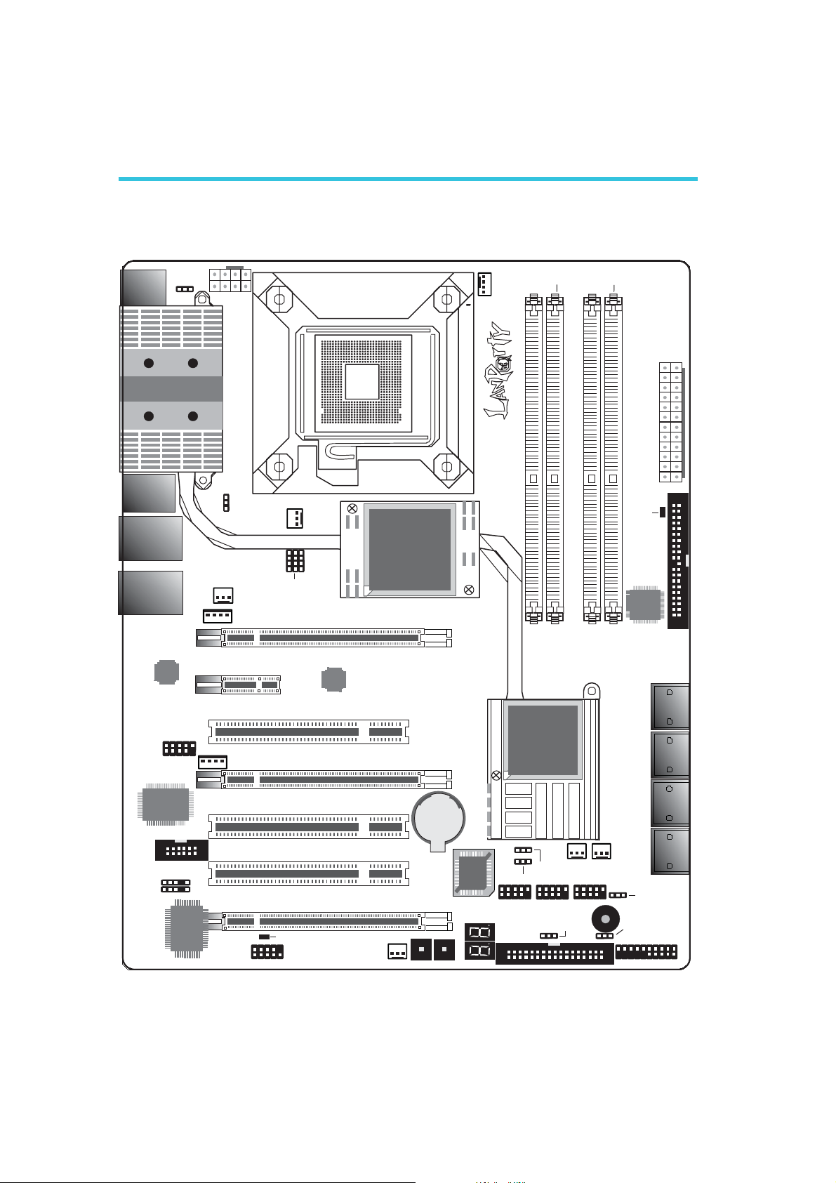
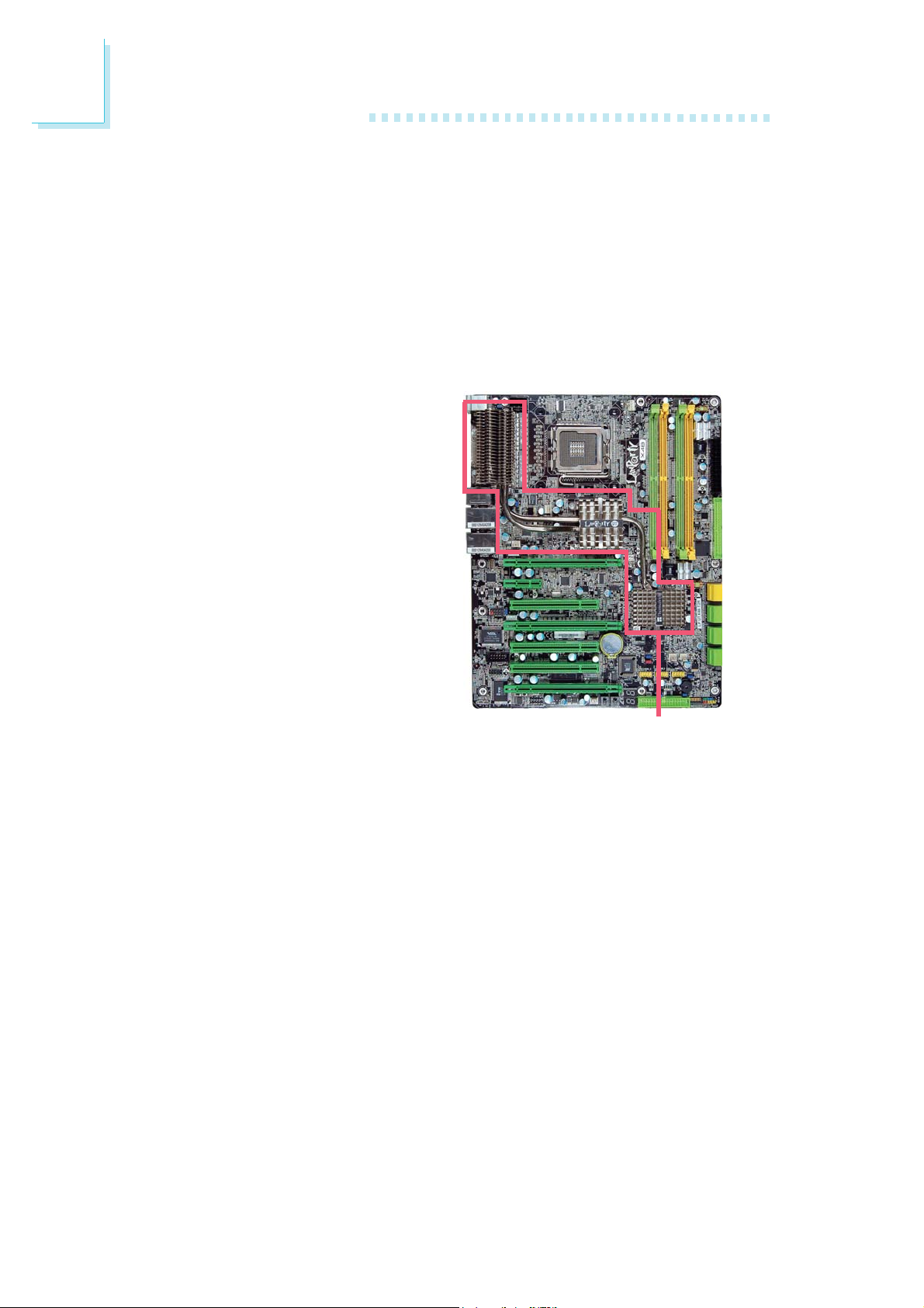
System Board Layout
Mouse
KB
1394-0
USB 11USB 10
LAN 1
USB 9USB 8
LAN 2
USB 7USB 6
PS/2 power
select (JP7)
Marvell
88E8053
1394-1
1
1
1
1
1
12V power
1
3rd fan
1
USB 6-11 power
select (JP5)
JP14
5V/12V
PCIE 2
5V/12V
power
NB fan
1
JP15
1
JP13
CPU FSB select
PCI 1
PCIE 3
PCIE 1
Marvell
88E8052
Socket 775
Intel
X48
1
CPU
fan
C217
DIMM 2 DIMM 4
DIMM 1
DIMM 3
DRAM
Power
LED
JMicron
JMB363
ATX
power
1
SATA 7
SATA 8
2412
13
1
IDE
Intel
ICH9R
SATA 1
SATA 2
16
VIA
VT6307
Bernstein audio
IrDA
1
1
CIR
1
ITE
IT8718F
1
PCI 2
PCI 3
PCIE 4
Standby Power LED
COM
1
2nd fan
Battery
Reset Power
BIOS
1
1
Clear
CMOS (JP2)
1
USB 4-5
USB 0-5 power
FDD
1
1st fan
Secondary RTC
reset (JP12)
1
USB 2-3
select (JP6)
1
USB 0-1
1
1
1
System
fan
1
Speaker on/off
(JP8)
1
Safe boot
(JP1)
Front panel
SATA 3
SATA 4
SATA 5
SATA 6
1
Warning:
.
.
.
.
.
.
.
.
.
.
.
.
.
.
.
.
Electrostatic discharge (ESD) can damage your system board, processor, disk drives, add-in boards, and other components. Perform the
upgrade instruction procedures described at an ESD workstation only.
If such a station is not available, you can provide some ESD protection by wearing an antistatic wrist strap and attaching it to a metal
part of the system chassis. If a wrist strap is unavailable, establish
and maintain contact with the system chassis throughout any procedures requiring ESD protection.
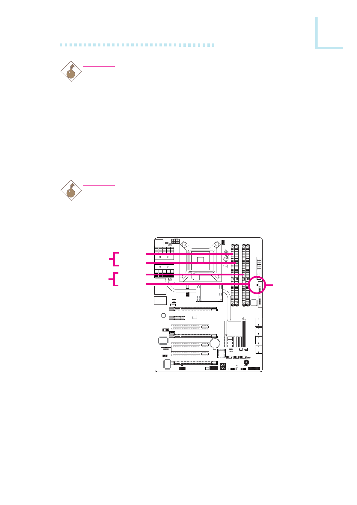
System Memory
Warning:
When the DRAM Power LED lit red, it indicates that power is
present on the DIMM sockets. Power-off the PC then unplug the
power cord prior to installing any memory modules. Failure to do so
will cause severe damage to the motherboard and components.
Hardware Installation
2
Channel A
DIMM 2
DIMM 3
DIMM 1
Channel B
DIMM 4
DRAM
Power LED
The four DIMM sockets on the system board are divided into 2
channels:
Channel A - DIMM 1 and DIMM 2
Channel B - DIMM 3 and DIMM 4
17

2
Hardware Installation
The system board supports the following memory interface.
Single Channel (SC)
Data will be accessed in chunks of 64 bits (8B) from the memory
channels.
Virtual Single Channel (VSC)
If both channels are populated with different memory configurations,
the MCH defaults to Virtual Single Channel.
Dual Channel (DC)
Dual channel provides better system performance because it doubles
the data transfer rate.
Dynamic Mode Addressing
This mode minimizes the overhead of opening/closing pages in
memory banks allowing for row switching to be done less often.
Single Channel
Virtual Single
Channel
Dual Channel
Dynamic Mode
Addressing
DIMMs are on the same channel.
DIMMs in a channel can be identical or completely different.
Not all slots need to be populated.
DIMMs of different memory configurations
are on different channels.
Odd number of slots can be populated.
DIMMs of the same memory configuration
are on different channels.
In single channel, requires even number or
rows (side of the DIMM) populated. This
mode can be enabled with 1 SS, 2 SS or
2 DS.
In VSC mode, both channels must have
identical row structure.
18
BIOS Setting
Configure the system memory in the Genie BIOS Setting submenu
of the BIOS. Refer to chapter 3 for more information.

Hardware Installation
The table below lists the various optimal operating modes that should
be configured for the memory channel operation.
2
Config
No memory
Single channel A
Single channel A
Single channel A
Single channel B
Single channel B
Single channel B
Virtual single channel
Virtual single channel
Virtual single channel
Virtual single channel
Virtual single channel
Virtual single channel
DIMM 1
E
P
P
E
E
E
E
E
E
E
P
P(**)
p(**)
DIMM 2
E
E
P
P
E
E
E
P(**)
P
P(**)
E
E
E
DIMM 3
E
E
E
E
P
P
E
E
P
P
E
P(**)
P(**)
DIMM 4
E
E
E
E
E
P
P
P(**)
E
P(**)
P
E
P
Virtual single channel
Virtual single channel
Virtual single channel
Dual channel
Dual channel
Dual channel
Continued on the next page...
P
P(**)
P(**)
E
P(*)(1,3)
P(*)(1,3)
P(**)
P
P(**)
P(*)(2,4)
E
P(*)(2,4)
E
P(**)
P(**)
E
P(*)(1,3)
P(*)(1,3)
P(**)
E
P(**)
P(*)(2,4)
E
P(*)(2,4)
19

2
Hardware Installation
Config
Dynamic Mode Addressing
Dynamic Mode Addressing
Dynamic Mode Addressing
Dynamic Mode Addressing
Dynamic Mode Addressing
Dynamic Mode Addressing
P - denotes populated
E - denotes empty
* - denotes DIMMs are identical
** - denotes DIMMs are not identical
SS - denotes Single Sided DIMM
DS - denotes Double Sided DIMM
1, 2, 3 or 4 - denotes the DDR DIMM slot
DIMM 1
E
P(*)(1,3)
DS
P(*)(1,3)
DS
E
P(*)(1,3)
SS
P(*)(1,3)
SS
DIMM 2
P(*)(2,4)
DS
E
P(*)(2,4)
DS
P(*)(2,4)
SS
E
P(*)(2,4)
SS
DIMM 3
E
P(*)(1,3)
DS
P(*)(1,3)
DS
E
P(*)(1,3)
SS
P(*)(1,3)
SS
DIMM 4
P(*)(2,4)
DS
E
P(*)(2,4)
DS
P(*)(2,4)
SS
E
P(*)(2,4)
SS
20
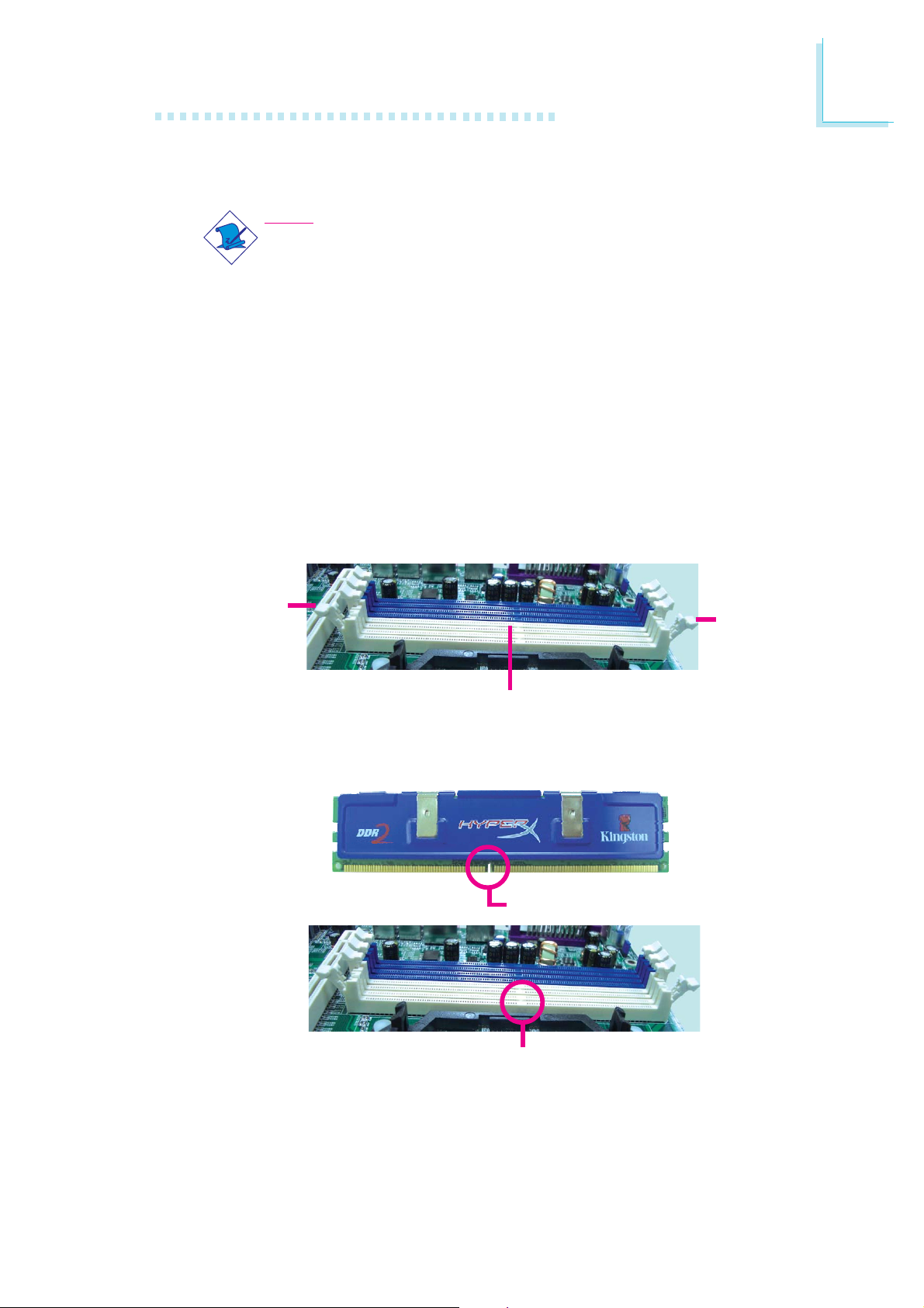
Installing the Memory Module
Note:
The system board used in the following illustrations may not
resemble the actual board. These illustrations are for reference
only.
1. Make sure the PC and all other peripheral devices connected to
it has been powered down.
2. Disconnect all power cords and cables.
3. Locate the DIMM socket on the system board.
4. Push the “ejector tabs” which are at the ends of the socket to
the side.
Hardware Installation
2
Ejector
tab
DIMM sockets
5. Note how the module is keyed to the socket.
Notch
Ejector
tab
Key
21
2
Hardware Installation
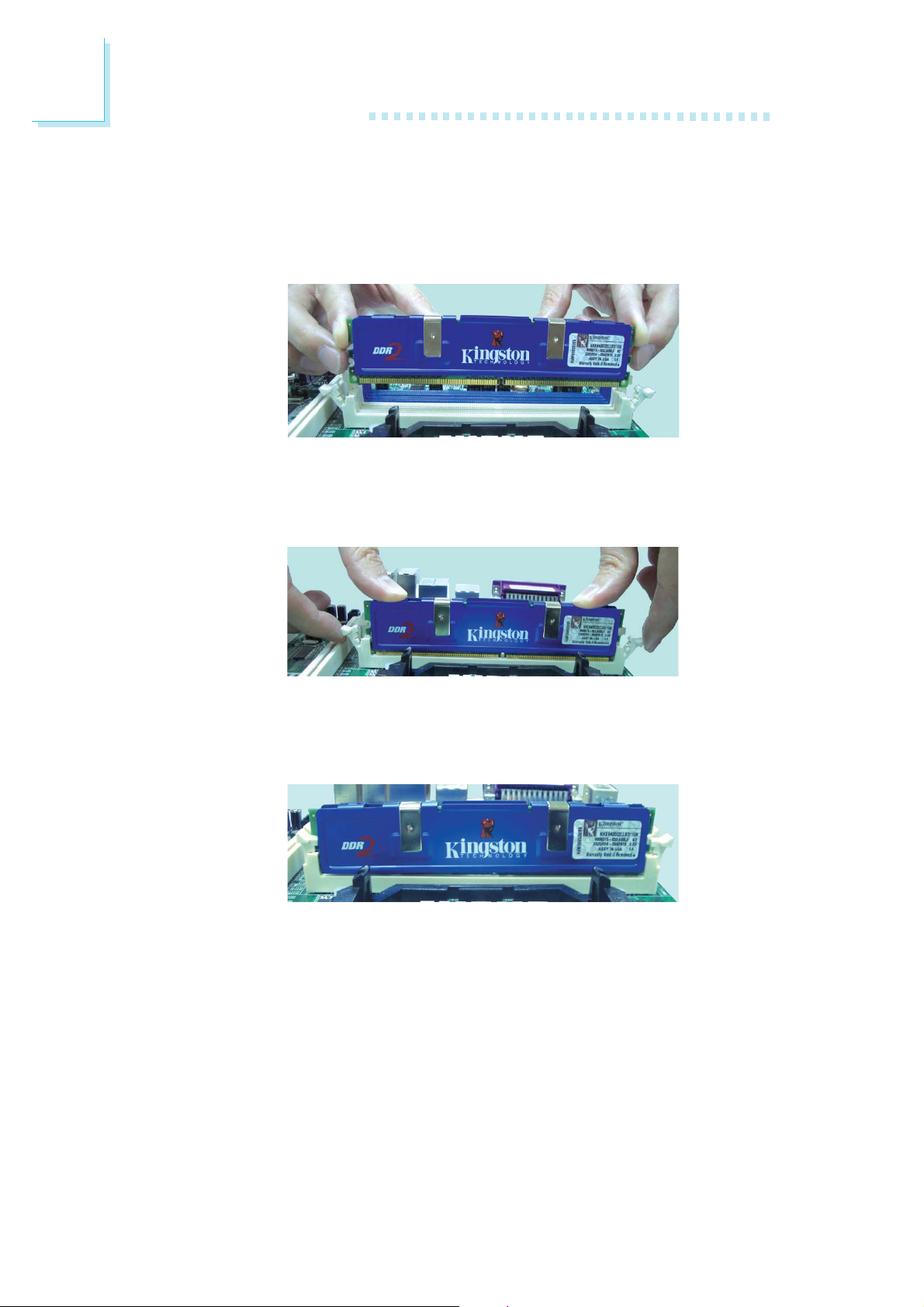
6. Grasping the module by its edges, position the module above
the socket with the “notch” in the module aligned with the “key”
on the socket. The keying mechanism ensures the module can be
plugged into the socket in only one way.
7. Seat the module vertically, pressing it down firmly until it is completely seated in the socket.
8. The ejector tabs at the ends of the socket will automatically
snap into the locked position to hold the module in place.
22
Hardware Installation
CPU
Overview
The system board is equipped with a surface mount LGA 775 socket. This
socket is exclusively designed for installing a LGA 775 packaged Intel
CPU.
Important:
1. Before you proceed, make sure (1) the LGA775 socket1. Before you proceed, make sure (1) the LGA775 socket
1. Before you proceed, make sure (1) the LGA775 socket
1. Before you proceed, make sure (1) the LGA775 socket1. Before you proceed, make sure (1) the LGA775 socket
comes with a protective cap, (2) the cap is not dam-comes with a protective cap, (2) the cap is not dam-
comes with a protective cap, (2) the cap is not dam-
comes with a protective cap, (2) the cap is not dam-comes with a protective cap, (2) the cap is not dam-
aged and (3) the socket’s contact pins are not bent. Ifaged and (3) the socket’s contact pins are not bent. If
aged and (3) the socket’s contact pins are not bent. If
aged and (3) the socket’s contact pins are not bent. Ifaged and (3) the socket’s contact pins are not bent. If
the cap is missing or the cap and/or contact pins arethe cap is missing or the cap and/or contact pins are
the cap is missing or the cap and/or contact pins are
the cap is missing or the cap and/or contact pins arethe cap is missing or the cap and/or contact pins are
damaged,damaged,
damaged,
damaged,damaged,
2. Make sure to keep the protective cap. RMA requests2. Make sure to keep the protective cap. RMA requests
2. Make sure to keep the protective cap. RMA requests
2. Make sure to keep the protective cap. RMA requests2. Make sure to keep the protective cap. RMA requests
will be accepted and processed only if the LGA775will be accepted and processed only if the LGA775
will be accepted and processed only if the LGA775
will be accepted and processed only if the LGA775will be accepted and processed only if the LGA775
socket comes with the protective cap.socket comes with the protective cap.
socket comes with the protective cap.
socket comes with the protective cap.socket comes with the protective cap.
contact your dealer immediately contact your dealer immediately
contact your dealer immediately
contact your dealer immediately contact your dealer immediately
..
.
..
2
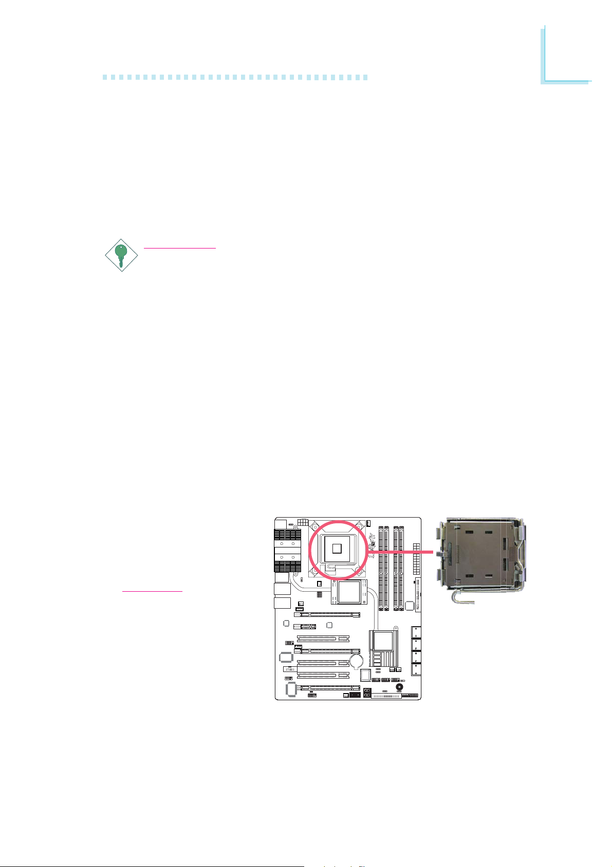
Installing the CPU
1. Make sure the PC and all other peripheral devices connected to it has
been powered down.
2. Disconnect all power cords and cables.
3. Locate the LGA 775
CPU socket on the
system board.
Important:
The CPU socket must
not come in contact with
anything other than the
CPU. Avoid unnecessary
exposure. Remove the
protective cap only when
you are about to install
the CPU.
23
2
Hardware Installation
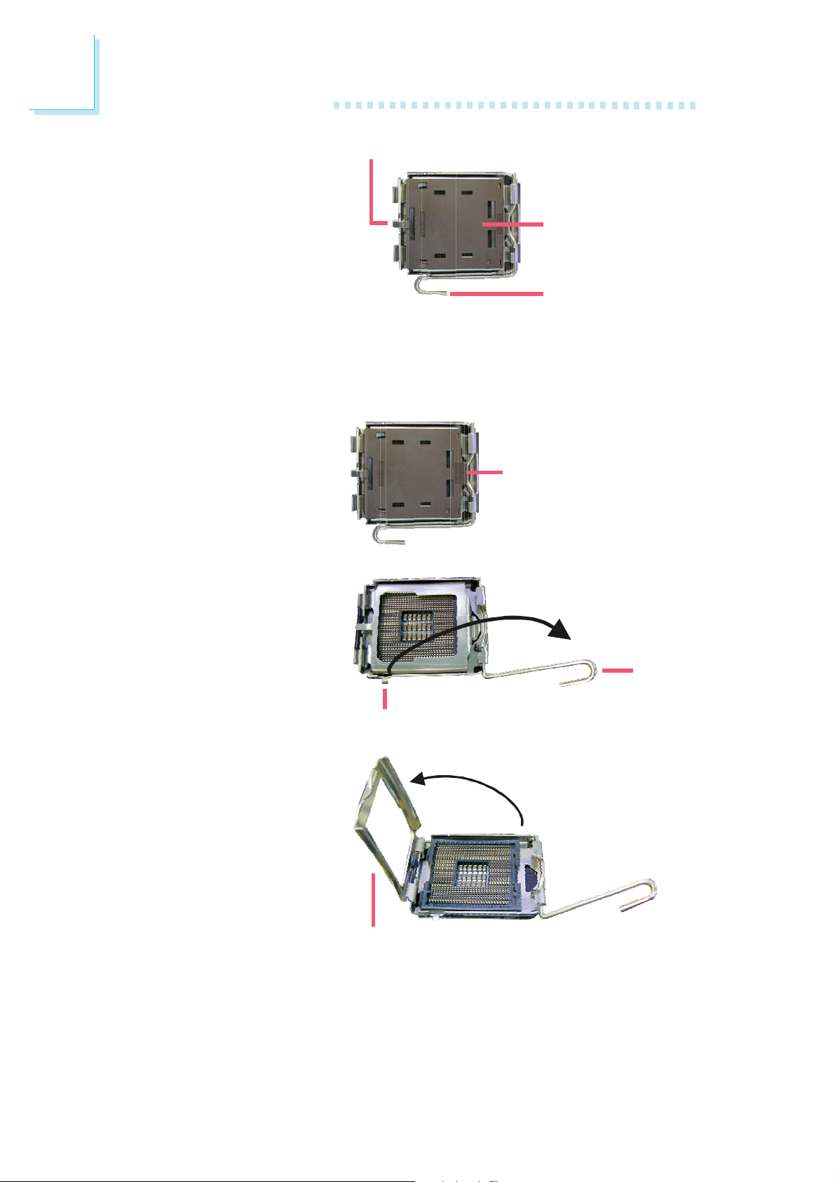
4. The CPU socket comes
with a cover that is
attached with a removable protective cap. The
cap is used to protect
the CPU socket against
dust and harmful particles. Remove the protective cap only when you
are about to install the
CPU.
5. Lift the protective cap
from the location
pointed below to detach
the cap from the cover.
Cover
Protective cap
Lever
Lift this part up
6. Unlock the socket by
pushing the lever down,
moving it away from the
side tab of the socket,
then lifting it up.
7. Now lift the cover.
Lever
lifted
Ta b
Cover
24
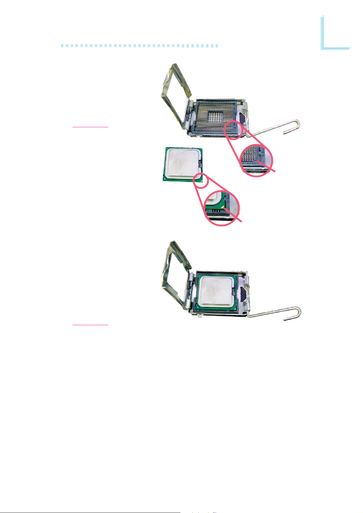
8. Position the CPU above
the socket. The gold
mark on the CPU must
align with pin 1 of the
CPU socket.
Important:
Handle the CPU by its
edges and avoid touching the pins.
Hardware Installation
2
Pin 1 of
the socket
9. Insert the CPU into the
socket until it is seated
in place. The CPU will fit
in only one orientation
and can easily be inserted without exerting
any force.
Important:
Do not force the CPU
into the socket. Forcing
the CPU into the socket
may bend the pins and
damage the CPU.
Gold mark
25
2
Hardware Installation
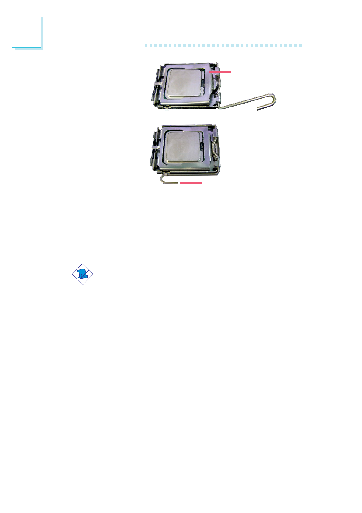
10. Once the CPU is in
place, move the cover
down.
11. Push the lever down to
lock the socket. The
lever should hook onto
the side tab to indicate
that the CPU is completely secured in the
socket.
Installing the Fan and Heat Sink
Cover
Lever
The CPU must be kept cool by using a CPU fan with heat sink.
Without sufficient air circulation across the CPU and heat sink, the
CPU will overheat damaging both the CPU and system board.
Note:
• Use only certified fan and heat sink.
• The fan and heat sink package usually contains the fan and
heat sink assembly, and an installation guide. If the installation procedure in the installation guide differs from the one
in this section, please follow the installation guide in the
package.
1. Before you install the fan / heat sink, you must apply a thermal
paste onto the top of the CPU. The thermal paste is usually
supplied when you purchase the CPU or fan heat sink assembly.
Do not spread the paste all over the surface. When you later
place the heat sink on top of the CPU, the compound will disperse evenly.
26
Do not apply the paste if the fan / heat sink already has a patch
of thermal paste on its underside. Peel the strip that covers the
paste before you place the fan / heat sink on top of the CPU.
Hardware Installation
2
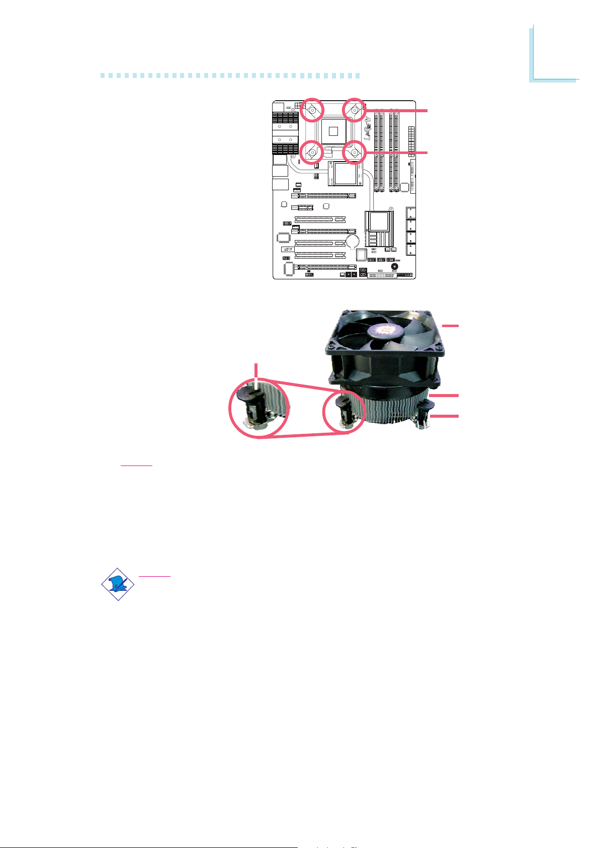
2. Place the heat sink on
top of the CPU. The 4
studs around the heat
sink which are used to
secure the heat sink
onto the system board
must match the 4
mounting holes around
the socket.
Position each stud so
that the groove faces
the heat sink then push
it down firmly until it
clicks into place.
Groove
Mounting hole
Mounting hole
Fan
Heat sink
Stud
Note:
You will not be able to secure the fan and heat sink assembly in place
if the groove is not facing the heat sink.
3. Connect the CPU fan’s cable connector to the CPU fan connector on
the system board.
Note:
LP UT series provides the option of using the Transpiper heat sink.
However, instead of using the push-pin type of CPU heat sink / fan
assembly, opt for an assembly that uses mounting screws. Refer to
the Transpiper Heat Sink section for details.
27
2
Hardware Installation
Flame-Freezer Heat Sink
The heat dissipating effect of a heat sink mounted directly at the place
where the heat is produced, such as that of a northbridge, is usually limited. To overcome this problem, the system board uses the heat pipe
technology which is an extremely high thermal conductor that can dissipate
heat effectively. The Flame-Freezer heat sink when installed at the rear of
the chassis provides additional cooling to the entire system.
1. The right photo shows the heat
pipe assembly on the system
board.
Heat pipe
assembly
28
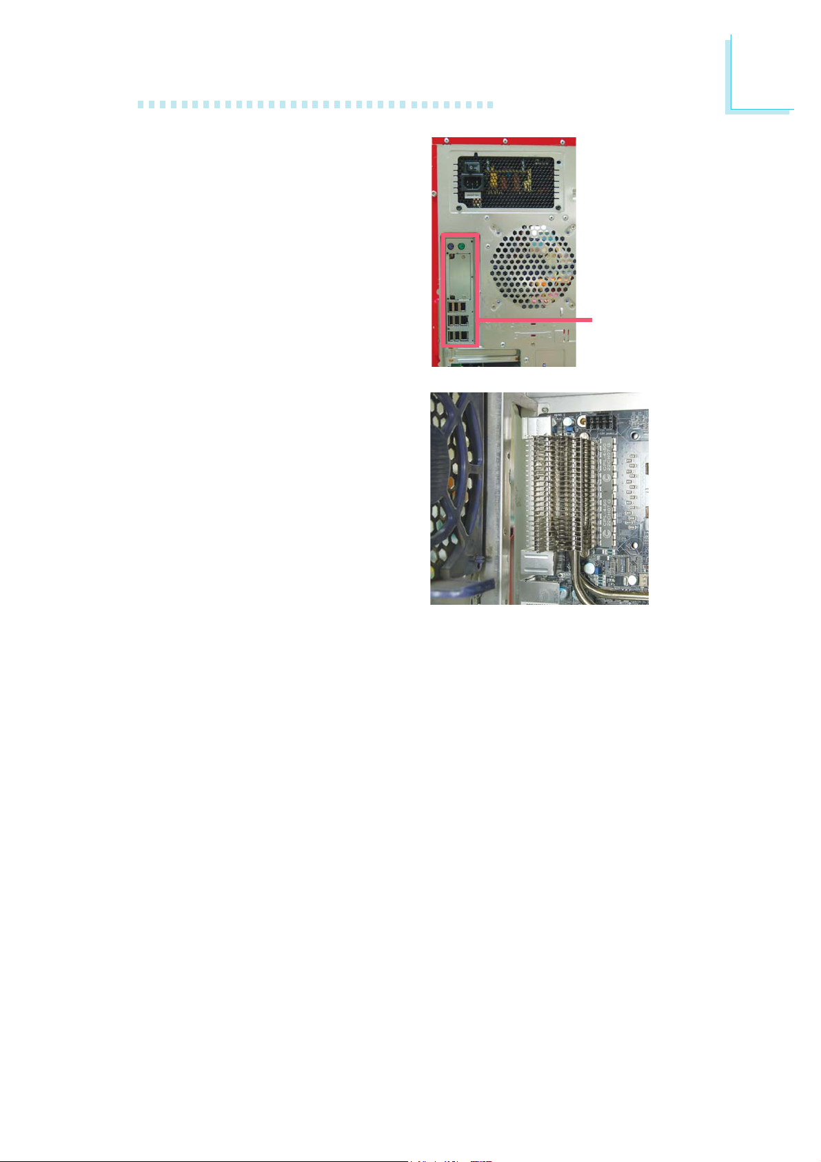
2. Before you proceed, make sure
you have already installed the
provided I/O shield and system
board into the chassis.
Hardware Installation
2
I/O shield
Internal view of the chassis
(rear I/O area)
29
2
Hardware Installation
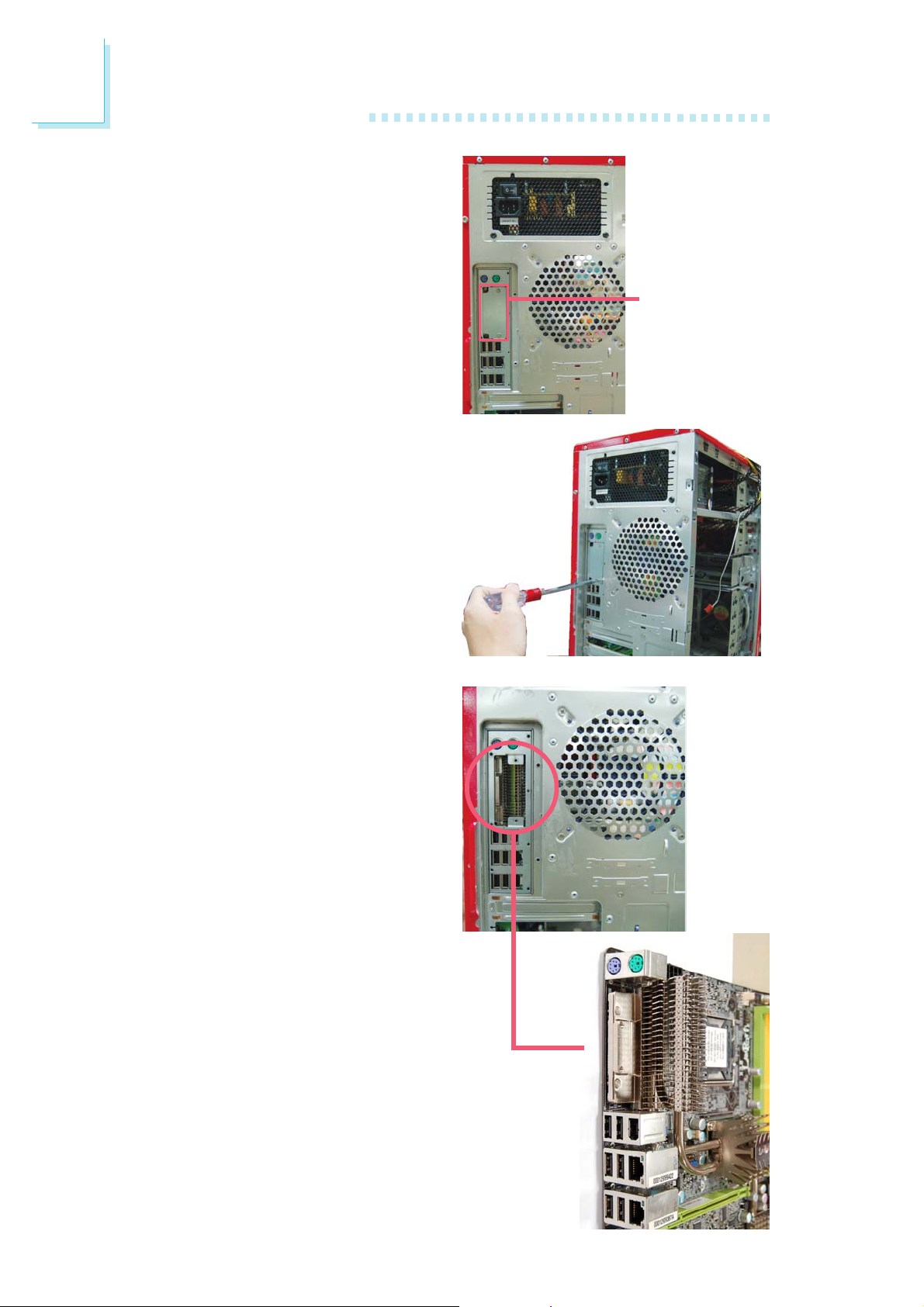
3. Remove the screws that hold the
metal-plate-covering of the I/O
shield.
Metal-plate-covering
of the I/O shield
4. The base of the heat sink which
is used to stabilize the FlameFreezer heat sink is now
accessible.
X
Heat sink base
30
Enlarged view of the
heat sink base