


LANPARTY UT NF4 SLI EXPERT User Guide

System Board
User’s Manual
935-NF4E91-000G
87910551

Copyright
This publication contains information that is protected by copyright.
No part of it may be reproduced in any form or by any means or
used to make any transformation/adaptation without the prior
written permission from the copyright holders.
This publication is provided for informational purposes only. The
manufacturer makes no representations or warranties with respect to
the contents or use of this manual and specifically disclaims any
express or implied warranties of merchantability or fitness for any
particular purpose. The user will assume the entire risk of the use or
the results of the use of this document. Further, the manufacturer
reserves the right to revise this publication and make changes to its
contents at any time, without obligation to notify any person or
entity of such revisions or changes.
© 2005. All Rights Reserved.
Trademarks
Product names or trademarks appearing in this manual are for
identification purpose only and are the properties of the respective
owners.

FCC and DOC Statement on Class B
This equipment has been tested and found to comply with the limits
for a Class B digital device, pursuant to Part 15 of the FCC rules.
These limits are designed to provide reasonable protection against
harmful interference when the equipment is operated in a residential
installation. This equipment generates, uses and can radiate radio
frequency energy and, if not installed and used in accordance with
the instruction manual, may cause harmful interference to radio
communications. However, there is no guarantee that interference
will not occur in a particular installation. If this equipment does cause
harmful interference to radio or television reception, which can be
determined by turning the equipment off and on, the user is
encouraged to try to correct the interference by one or more of the
following measures:
• Reorient or relocate the receiving antenna.
• Increase the separation between the equipment and the receiver.
• Connect the equipment into an outlet on a circuit different from
that to which the receiver is connected.
• Consult the dealer or an experienced radio TV technician for
help.
Notice:
1. The changes or modifications not expressly approved by the
party responsible for compliance could void the user's authority
to operate the equipment.
2. Shielded interface cables must be used in order to comply with
the emission limits.

Table of Contents
About this Manual................................................................................
Warranty.....................................................................................................
Static Electricity Precaution................................................................
Safety Measures.....................................................................................
About the Package...............................................................................
Before Using the System Board.........................................................
Français....................................................................................................
Deutsch....................................................................................................
Español....................................................................................................
Русский язык............................................................................................
Chapter 1 - Introduction....................................................................
Specifications...................................................................................................................................
Special Features of the System Board..................................................................
Chapter 2 - Hardware Installation....................................................
System Board Layout ..........................................................................................................
System Memory..........................................................................................................................
CPU.......................................................................................................................................................
Jumper Settings............................................................................................................................
Rear Panel I/O Ports.............................................................................................................
I/O Connectors..........................................................................................................................
SLI Technology................................................................................................................................
5
5
6
6
7
7
9
11
13
15
17
17
21
26
26
27
31
37
44
55
77
Chapter 3 - BIOS Setup......................................................................
Award BIOS Setup Utility.................................................................................................
NVRAID BIOS............................................................................................................................
Sil3114 SataRAID BIOS.....................................................................................................
Updating the BIOS..................................................................................................................
Chapter 4 - Supported Softwares.....................................................
Drivers, Utilities and Software Applications......................................................
Installation Notes.......................................................................................................................
Appendix A - System Error Messages...............................................
Error Messages.........................................................................................................................
Appendix B - Troubleshooting..........................................................
Troubleshooting Checklist...............................................................................................
84
84
129
129
130
132
132
145
146
146
148
148

About this Manual
This user’s manual contains detailed information about the system
board. If, in some cases, some information doesn’t match those
shown in the multilingual manual, the multilingual manual should always be regarded as the most updated version. The multilingual
manual is included in the system board package.
To view the user’s manual, insert the CD into a CD-ROM drive. The
autorun screen (Mainboard Utility CD) will appear. Click the
“TOOLS” icon then click “Manual” on the main menu.
Warranty
1. Warranty does not cover damages or failures that arised from
misuse of the product, inability to use the product, unauthorized
replacement or alteration of components and product
specifications.
2. The warranty is void if the product has been subjected to
physical abuse, improper installation, modification, accidents or
unauthorized repair of the product.
3. Unless otherwise instructed in this user’s manual, the user may
not, under any circumstances, attempt to perform service,
adjustments or repairs on the product, whether in or out of
warranty. It must be returned to the purchase point, factory or
authorized service agency for all such work.
4. We will not be liable for any indirect, special, incidental or
consequencial damages to the product that has been modified
or altered.

1
Introduction
Static Electricity Precautions
It is quite easy to inadvertently damage your PC, system board,
components or devices even before installing them in your system
unit. Static electrical discharge can damage computer components
without causing any signs of physical damage. You must take extra
care in handling them to ensure against electrostatic build-up.
1. To prevent electrostatic build-up, leave the system board in its
anti-static bag until you are ready to install it.
2. Wear an antistatic wrist strap.
3. Do all preparation work on a static-free surface.
4. Hold the device only by its edges. Be careful not to touch any of
the components, contacts or connections.
5. Avoid touching the pins or contacts on all modules and
connectors. Hold modules or connectors by their ends.
Important:
Electrostatic discharge (ESD) can damage your processor, disk
drive and other components. Perform the upgrade instruction
procedures described at an ESD workstation only. If such a
station is not available, you can provide some ESD protection
by wearing an antistatic wrist strap and attaching it to a metal
part of the system chassis. If a wrist strap is unavailable,
establish and maintain contact with the system chassis
throughout any procedures requiring ESD protection.
Safety Measures
To avoid damage to the system:
• Use the correct AC input voltage range
To reduce the risk of electric shock:
• Unplug the power cord before removing the system chassis
cover for installation or servicing. After installation or servicing,
cover the system chassis before plugging the power cord.
..
.
..
Battery:
• Danger of explosion if battery incorrectly replaced.
• Replace only with the same or equivalent type recommend
the manufacturer.
• Dispose of used batteries according to the battery
manufacturer’s
instructions.
by
6

About the Package
The system board package contains the following items. If any of
these items are missing or damaged, please contact your dealer or
sales representative for assistance.
; One system board
; One Karajan audio module
; One SLI bridge
; Two IDE round cables
; One floppy round cable
; Four Serial ATA data cables
; Two Serial ATA power cables
; One I/O shield
; One SATA driver diskette (for NVRAID and Silicon Image Sil
3114 RAID)
; One “Mainboard Utility” CD
; One user’s manual
; One Quick Installation Guide
Introduction
1
The system board and accessories in the package may not come
similar to the information listed above. This may differ in accordance
to the sales region or models in which it was sold. For more
information about the standard package in your region, please
contact your dealer or sales representative.
Before Using the System Board
Before using the system board, prepare basic system components.
If you are installing the system board in a new system, you will need
at least the following internal components.
• A CPU
• Memory module
• Storage devices such as hard disk drive, CD-ROM, etc.
You will also need external system peripherals you intend to use
which will normally include at least a keyboard, a mouse and a video
display monitor.
7

1
Introduction
Frequent Q&A on Memory Usage
Q: How can I obtain good performance on an overclocked system?
A: Insert two identical broad bandwidth memories in DIMM 2 and
DIMM 4.
Q: Why will the system board fail to boot when 3 DIMMs are
used?
A: The integrated memory controller in AMD's 64-bit Socket 939
series CPU supports dual channel however the controller is not
capable of accurately distinguishing between dual and single
channels resulting to boot up problem. If you have luckily
booted the system, the total memory size detected is from 2
DIMMs only, not 3. Therefore we do not suggest using 3
DIMMs.
Q: Why won't the system boot when 4 single side DIMMs are
used?
A: Normally, the memory timing is set at 2T but to enhance system
performance, the default memory timing has been fixed at 1T
(Command Per Clock: Enabled). Therefore if you use 4 single side
DIMMs, the load will exceed the limit (DDR 400). Please refer to
the steps below to solve this problem.
1. Set the "DRAM Voltage Control" field (in the Genie BIOS
Setting of the Award BIOS) to "2.8V".
2. Set the memory timing to 2T by selecting Disabled in the
"Command Per Clock" field (in the Genie BIOS Setting of the
Award BIOS).
8

Français
Caractéristiques et Spécifications
Introduction
1
Processeur
• AMD Athlon
• Interface HyperTransport 2000MT/s
• Socket 939
Chipset
• NVIDIA nForce4
- Supporte NVIDIA SLI
Mémoire Système
• 4 sockets DDR SDRAM DIMM 184 broches
• Supporte l’interface de mémoire deux canaux (128-bit)
• Supporte jusqu’à 4GB de mémoire
• Supporte DDR SDRAM DIMM PC2100 (DDR266), PC2700 (DDR333) et
PC3200 (DDR400)
• Supporte exclusivement les modules DIMM non-ECC x8/x16, densité de
RAM jusqu’à 512Mb, DIMM non-tamponnés
Logements d’Extension
• 2 slots PCI Express x16
• 1 slot PCI Express x1
• 1 slot PCI Express x4
• 3 slots PCI
Mode SLI ou Mode VGA Seul
• SLI mode
- 2 cartes graphiques SLI-ready (utiliser des cartes identiques) sur les bus
PCI Express x16.
- La bande passante de chaque encoche est x8; Lorsque les cartes
graphiques sont connectées via le pont SLI, la bande passante est de x16.
• Mode VGA Seul
- 1 carte graphique PCI Express sur le bus PCIE1 fonctionnera avec une
bande passante de x16
- L’autre bus PCI Express x16 (PCIE4) fonctionnera avec une bande de x2.
TM
64 FX / AthlonTM 64 / Sempron
TM
SLI
TM
(Scalable Link Interface)
TM
BIOS
• Compatible avec Award BIOS
• CMOS Reloaded
• Overclocking de CPU/DRAM
• Contrôle du voltage de CPU/DRAM/Chipset
• Mémoire Flash 4Mbit
Design à Haut Rendement Énergétique
• ACPI STR (Suspend to RAM) fonction
• Réveil-Sur-PS/2 Clavier/Souris et Réveil-Sur-USB Clavier/Souris
• Réveil Par Le Réseau et minuterie RTC pour allumer le système
• Récupération après Défaillance d’Alimentation CA
System Health Monitor Fonctions
• Gère l’alarme de température et de surchauffe de CPU/système/chipset
• Gère l’alarme de voltage et d’échec de 12V/5V/3.3V/Vcore/Vbat/5Vsb/
Vchipset/Vdram
• Gère la vitesse de ventilateur du ventilateur de CPU/Fan2/Fan3
• Protection du CPU - supporte la mise hors circuit automatique en cas de
surchauffage du système
9

1
Introduction
Caractéristiques Audio sur Carte
• Karajan carte audio
- AC’97 CODEC Realtek ALC850 8-canaux
- 6 prises audio, 1
• Sorties de niveau de lignes stéréo vraies; interface entrée/sor tie S/PDIF
Fonctionnalités Onboard LAN
• Deux Gigabit LAN - Vitesse VSC8201 Gigabit Phy et Marvell 88E8001
Gigabit PCI
• Supporte IEEE 802.3 (10BASE-T), 802.3u (100BASE-TX) et 802.3ab
(1000BASE-T)
• Fonctions de gestion d’alimentation intégrées
• Support câble pour la gestion
Interface IDE avec NVIDIA RAID
• Supporte des disques durs jusqu’à UltraDMA 133Mbps
• NVIDIA RAID permet des ensembles RAID sur toute l’étendue du port de
série ATA et du parallèle ATA
• RAID 0, RAID 1, RAID 0+1 et JBOD
Interface Série ATA avec RAID
• Quatre por ts de série ATA gérés avec la puce nForce4 SLI (pour les
LANPARTY UT NF4 SLI-D Expert uniquement)
- Vitesse SATA jusqu’à 3Gb/s; RAID 0, RAID 1, RAID 0+1 et JBOD
- NVIDIA RAID permet des ensembles RAID sur toute l’étendue du port
de série ATA et du parallèle ATA
• Quatre por ts de série ATA gérés par Silicon Image Sil 3114 (pour les
LANPARTY UT NF4 SLI-DR Expert uniquement)
- Vitesse SATA jusqu’à 1.5Gb/s; RAID 0, RAID 1, RAID 0+1 et RAID 5
connecteur CD-in et 1 connecteur audio de l’avant
Interface IEEE 1394
• VIA VT6307; supporte 2 ports 100/200/400 Mb/séc
Le Panneau des Ports Entrée/Sortie en Arrière
• 1 port souris PS/2 et 1 port clavier PS/2
• 2 S/PDIF RCA prises (S/PDIF-in et S/PDIF-out)
• 1 carte Karajan (6 prises audio)
• 1 port IEEE 1394, 2 ports RJ45 LAN et 6 ports USB 2.0/1.1
Connecteurs Entrée/Sortie
•
2 connecteurs pour 4 ports USB 2.0/1.1 supplémentaires
• 1 connecteur pour 1 IEEE 1394
• 1 connecteur pour 1 série
• 1 connecteur pour module audio Karajan
• 1 connecteur audio frontal pour les jacks de sortie externe et d’entrée
micro (sur le module audio Karajan)
•1
• 1 S/PDIF l’assemblage pour l’adjonction de câble optique
• 1 connecteur IR, 2 connecteurs IDE et 1 connecteur de 90
•8
• 1 connecteur d’alimentation 24-pin ATX
• 1 connecteur d’alimentation 8-pin 12V ATX
• 1 prises d’alimentation 4-broches 5V/12V (type-FDD)
• 1 connecteur devant panneau et 5 connecteurs de ventilateurs
• 4 indicateurs diagnostiques et EZ interrupteurs (bouton de power et reset)
connecteur CD-in audio internes (sur le module audio Karajan)
o
FDD
connecteurs Serial ATA (pour les modèles LANPARTY UT NF4 SLI-DR
Expert uniquement)
4
connecteurs Serial ATA (pour les LANPARTY UT NF4 SLI-D Expert
uniquement)
10
PCB
• ATX, 24cm (9.45") x 30.5cm (12")

Deutsch
Leistungsmerkmale und Technische Daten
Introduction
1
Prozessor
• AMD Athlon
• Interface HyperTransport 2000MT/s
• Socket 939
Chipset
• NVIDIA nForce4
- Unterhält NVIDIA SLI
Systemspeicher
• 4 sockets DDR SDRAM DIMM 184 broches
• Supporte l’interface de mémoire deux canaux (128-bit)
• Supporte jusqu’à 4GB de mémoire
• Supporte DDR SDRAM DIMM PC2100 (DDR266), PC2700 (DDR333) et
PC3200 (DDR400)
• Supporte exclusivement les modules DIMM non-ECC x8/x16, densité de
RAM jusqu’à 512Mb, DIMM non-tamponnés
Erweiterungssteckfasssungen
• 2 PCI Express x16-Einbauplätzen
• 1 PCI Express x1-Einbauplätzen und 1 PCI Express x4-Einbauplätzen
• 3 PCI-Einbauplätzen
SLI-Modus oder Single-VGA-Modus
• SLI-Modus
- 2 SLI-kompatible Grafikkarten (bitte identische Karten verwenden) in den
Steckplätzen für PCI Express x16
- Die Bandbreite der Steckplätze beträgt jeweils x8; wenn die Grafikkarten
per SLI-Verbindung angeschlossen sind, beträgt die Bandbreite x16.
• Single-VGA-Modus
- 1 PCI Express Grafikkarte im Steckplatz für PCIE1 läuft mit x16-
Bandbreite.
- Der zweite Steckplatz für PCI Express x16 (PCIE4) läuft mit doppelter
Bandbreite.
TM
64 FX / AthlonTM 64 / Sempron
TM
SLI
TM
(Scalable Link Interface)
TM
BIOS
• Kompatibilität mit Award BIOS, Flash-Speicher (4Mbit); CMOS Reloaded
• Die Frequenzerhöhung CPU/DRAM; Spannungserhöhung CPU/DRAM/Chipset
Energomisches Design
• ACPI STR (Suspend to RAM) funktion
• Wecken bei Betätigung PS/2 Tastatur/Maus und wecken bei USB-Tastatur/Maus
• Wecken des Systems durch das Netzwerk
• RTC-Taktgeber zum Einschalten des Systems
• Wiederherstellung der Wechselstromversorgung nach einem Ausfall
System Health Monitor Funktions
• Überwachung der Temperatur des CPU/System/Chipset sowie Warnsignal bei
Überhitzung
• Überwachung der Spannungen des 12V/5V/3.3V/Vcore/Vbat/5Vsb/Vchipset/
Vdram
• Überwachung der Geschwindigkeit des CPU-, Fan 2 und Fan 3-Ventilators
• Prozessor-Shutz - Die Ausschaltung bei der Überhitzung – die automatische
Ausschaltung des Computers bei der Überhitzung
11

1
Introduction
Audiomerkmale auf Platine
• Karajan-platine
- Realtek ALC850 8-Kanal, AC’97 Codec; 6 Audio-Anschlußbuchsen
- 1 interne Audioanschlüsse (CD-in) und 1 Frontaudioanschluß
• Naturgetreue Stereo-Leitungspegel-Ausgabe; S/PDIF-In/Aus-Schnittstelle
Merkmale des LAN auf Platine
• Zwei Gigabit LAN - Vitesse VSC8201 Gigabit Phy und Mar vell 88E8001
Gigabit PCI
• Unterstützt IEEE 802.3 (10BASE-T), 802.3u (100BASE-TX) und 802.3ab
(1000BASE-T)
• Integrierte Power-Management-Funktionen
• Unterstützung des Leiters für das Management
IDE-Schnittstelle mit NVIDIA RAID
• Unterstützung der Festplatten bis zum UltraDMA 133Mbps
• NVIDIA RAID ermöglicht, dass die RAID-Arrays sowohl serielle als auch
parallele ATA-Schnittstellen umfassen.
• RAID 0, RAID 1, RAID 0+1 und JBOD
Serielle ATA-Schnittstelle mit RAID
• Vier serielle Serial ATA-Ports, unterstützt von einem nForce4 SLI Chip (Nur
für die LANPARTY UT NF4 SLI-D Expert)
- SATA bis zu 3Gb/s schnell; RAID 0, RAID 1, RAID 0+1 und JBOD
- NVIDIA RAID ermöglicht, dass die RAID-Arrays sowohl serielle als auch
parallele ATA-Schnittstellen umfassen.
• Vier serielle ATA-Ports, unterstützt von Silicon Image Sil 3114 (Nur für die
LANPARTY UT NF4 SLI-DR Expert)
- SATA bis zu 1.5Gb/s schnell; RAID 0, RAID 1, RAID 0+1 und RAID 5
IEEE 1394 Schnittstelle
• VIA VT6307; uunterstützt 2 Ports 100/200/400 Mbps
Ein-/Ausgabe-Porte an der Rückwand
• 1 Mini-DIN-6-Anschluß für eine PS/2-Maus und PS/2-Tastatur
• 2 S/PDIF RCA-Anschlüsse (S/PDIF-in und S/PDIF-out)
• Karajan-platine (6 Audio-Anschlußbuchsen)
• 1 IEEE 1394-Anschlüsse und 2 RJ45 LAN-Anschlüsse
• 6 USB 2.0/1.1-Anschlüsse
Ein-/Ausgabe-Steckverbinder
•2
Anschlußfassung für 4 zusätzliche externe USB 2.0/1.1-Anschlüsse
• 1 Anschluß für eine externe IEEE 1394 Schnittstelle
• 1 Anschluß für eine externe serieller DB-9-Anschluß
• 1 Anschluß für eine Karajan Audiomodul
• 1 Front-Audioanschluss für externe Mikrofon-Ein- und –Ausgänge (im Karajan
Audiomodul)
• 1 CD-in interne Audioanschlüsse (im Karajan Audiomodul)
• 1 S/PDIF Anschluß für die Verbindung des optischen Kabel
• 1 Anschluß für die IR-Schnittstelle
• 8 Serial ATA-Anschlüsse (Nur für die Modelle LANPARTY UT NF4 SLI-DR Expert)
4 Serial ATA-Anschlüsse (Nur für die LANPARTY UT NF4 SLI-D Expert)
• 2 IDE-Anschlüsse und 1 90
• 1 24-polige Anschlußstecker für das ATX-Netzgerät
• 1 8-polige 12V Anschlußstecker für das ATX-Netzgerät
• 1 4-polige 5V/12V Netzstecker (für FDD)
• 1 Vorderseite Füllung Anschlüsse und 5-ventilator-Anschlüsse
• 4 diagnostischen Außenindikatoren
• EZ Umschaltern (der Knopf der Speisung und des Auslasses)
o
Floppy-Anschlüsse
12
Die Druckplatte
• ATX, 24cm (9.45") x 30.5cm (12")

Español
Características y Especificaciones
Introduction
1
Procesador
• AMD Athlon
• Interface de HyperTransport 2000MT/s
• Socket 939
Chipset
• NVIDIA nForce4TM SLI
- Soporta NVIDIA SLI
Memoria de Sistema
• 4 zocalos 184-pin DDR SDRAM DIMM
• Soporta memoria de dos canales (128-bit)
• Soporta hasta 4 GB de memoria sistémica
• Soporta PC2100 (DDR266), PC2700 (DDR333) y PC3200 (DDR400)
• Soporta sólo non-ECC x8/x16 DIMM, unbuffered, apoyo hasta 512 Mb
DRAM
Ranuras de Expansión
• 2 slot PCI Express x16
• 1 slot PCI Express x1 y 1 slot PCI Express x4
• 3 slots PCI
Tipo SLI o Tipo Individual de VGA
• Tipo SLI
- Dos tarjetas gráficas SLI-ready (utilice una placa madre) en el slot PCI
Express x16
- El ancho de banda de cada slot es x8; cuando las tarjetas gfráficas están
conectadas vía el puente de SLI, funciona en el ancho de banda de x16.
• Tipo Individual de VGA
- La tarjetas gráficas SLI Express en el slot PCIE1 correra en el ancho
banda x16
- El otro slot (PCIE4) de PCI Express x16 correra en el ancho banda x2.
TM
64 FX / AthlonTM 64 / Sempron
TM
(Scalable Link Interface)
TM
BIOS
• Award BIOS; Memoria Instante (4Mbitios)
• CMOS Reloaded
• Subida de frecuencia de CPU/DRAM
• Subida de voltaje de CPU/DRAM/Chipset
Diseño Energia Eficiente
• ACPI STR (Suspend to RAM) función
• PS/2 Teclado/Ratón de Wake-On y USB Teclado/Ratón de Wake-On
• Wake-On-LAN
• Temporizador de RTC para encender el sistema
• Recuperación de Fracaso de Energía AC
Funciones de Monitor de Salud del Sistema
• Monitores de los CPU/sistema/chipset temperaturas y alarma acalorada.
• Monitores de voltajes de 12V/5V/3.3V/Vcore/Vbat/5Vsb/Vchipset/Vdram
• Vigila la velocidad del abanico del abanido del CPU/Fan2/Fan3
• Protección del procesador - Desconección en caso de recalentamiento – el
ordenador se desconecta automáticamente en caso de recalentamiento
13

1
Introduction
Características de Audio En Tablero
• Tablero de Karajan
- Realtek ALC850 8-canal AC’97 CODEC; 6 enchufes de audio
- 1 conector de CD-in audio interno y 1 conectador audio delantero
• Auténtico salidas de nivel de línea estéreo
• Interfáz de S/PDIF-in/out
Características de LAN Interno
• Dos Gigabit LAN - Vitesse VSC8201 Gigabit Phy y Marvell 88E8001
Gigabit PCI
• Soporta IEEE 802.3 (10BASE-T), 802.3u (100BASE-TX) y 802.3ab
(1000BASE-T)
• Funciones de administración de energía integrado
• Soporta alambre para la administración
Interfaz IDE con NVIDIA RAID
• Soporta las unidades duras hasta de UltraDMA 133Mbps
• NVIDIA RAID permite RAID órdenes atravesando Serial ATA y Parallel ATA
• RAID 0, RAID 1, RAID 0+1 y JBOD
Interfaz en Serie ATA con RAID
• 4 ports de Serial ATA soporta por nForce4 SLI chip (para los LANPARTY
UT NF4 SLI-D Expert solamente)
- SATA se acelera a 3Gb/s; RAID 0, RAID 1, RAID 0+1 y JBOD
- NVIDIA RAID permite RAID órdenes atravesando Serial ATA y Parallel ATA
• 4 por ts de Serial ATA soporta por Silicon Image Sil 3114 (para los
LANPARTY UT NF4 SLI-DR Expert solamente)
- SATA se acelera a 1.5Gb/s; RAID 0, RAID 1, RAID 0+1 y RAID 5
Interfaz IEEE 1394
• VIA VT6307; soporta 2 ports 100/200/400 Má/sec
Panel de reverso de conectores de entrada - Salida
• 1 puerto de ratón PS/2 y 1 puerto de teclado PS/2
• 2 enchufes de S/PDIF RCA (S/PDIF-in y S/PDIF-out)
• 1 tablero de Karajan (6 enchufes de audio)
• 1 puerto de IEEE 1394 y 2 puertos de RJ45 LAN
• 6 puertos de USB 2.0/1.1
I/O Conectores
• 2 conectores para 4 puertos de USB 2.0/1.1 externo adicional
• 1 conector para un puerto de IEEE 1394
• 1 conector para un puerto de DB-9 serie externa
• 1 conector para un módulo de sonido de Karajan
• 1 connector de sonido delantera por linea externa y micrófono interno (en
el módulo de sonido de Karajan)
• 1 conector de CD-in audio interno (en el módulo de sonido de Karajan)
• 1 S/PDIF mortaja para conección de cable óptico
• 1 conector de IR, 2 conector de IDE y 1 conector de 90
• 8 conectores de Serial ATA (para los modelos LANPARTY UT NF4 SLI-DR
Expert solamente)
4 conectores de Serial ATA (para los LANPARTY UT NF4 SLI-D Expert
solamente)
• 1 conector 24-pin de fuente de alimentación de ATX
• 1 conector 8-pin 12V de fuente de alimentación de ATX
• 1 4-fichas conectadores de energía de 5V/12V (FDD-tipo)
• 1 conector de panel delante y 5 conectores de abanicos
• 4 indicadores diagnósticos
• EZ conmutadores (conmutadores de alimentación y reset)
o
FDD
14
La Placa Imprenta
• Form-factor ATX, 24cm (9.45") x 30.5cm (12")

Русский языкРусский язык
Русский язык
Русский языкРусский язык
Характеристики и свойстваХарактеристики и свойства
Характеристики и свойства
Характеристики и свойстваХарактеристики и свойства
ПроцессорПроцессор
Процессор
ПроцессорПроцессор
• AMD Athlon
• Интерфейс системной шины 2000MT/s
• Socket 939
ЧипсетЧипсет
Чипсет
ЧипсетЧипсет
• NVIDIA nForce4TM SLI
- Поддерживает NVIDIA SLI
Оперативная ПамятьОперативная Память
Оперативная Память
Оперативная ПамятьОперативная Память
• 4 184-pin DDR SDRAM DIMM
• Поддерживает двухканальный (128-битного) интерфейс
• Поддерживает до 4ГБ системной памяти
• Поддерживает PC2100 (DDR266), PC2700 (DDR333) и PC3200
(DDR400) DDR SDRAM DIMM
• Поддерживает только non-ECC x8/x16 DIMM, небуфф, Поддержка
до 512Mб DRAM
TM
64 FX / AthlonTM 64 / Sempron
TM
TM
(Scalable Link Interface)
Introduction
1
СлотыСлоты
Слоты
СлотыСлоты
• 2 PCI Express x16 слотов è 3 PCI слотов
• 1 PCI Express x1 слотов è 1 PCI Express x4 слотов
Pежим SLI mode или режим Single VGAPежим SLI mode или режим Single VGA
Pежим SLI mode или режим Single VGA
Pежим SLI mode или режим Single VGAPежим SLI mode или режим Single VGA
• Режим SLI
- 2 видеокарты SLI-ready (используйте одинаковые платы) на
слотах PCI Express x16
- Пропускная способность каждого слота составляет x8, когда
видеокарты соединены мостом SLI, она составляет x16.
• Режим одного VGA
- 1 видеокарта PCI Express на слоте PCIE1 работает с
пропускной способностью x16.
- Другой слот PCI Express x16 (PCIE4) работает с пропускной
способностью x2.
BIOSBIOS
BIOS
BIOSBIOS
• Award BIOS, 4Mbit Flash
• Повышение частоты CPU/DRAM
• Повышение напряжения CPU/DRAM/Chipset
Энергомичный ДизайнЭнергомичный Дизайн
Энергомичный Дизайн
Энергомичный ДизайнЭнергомичный Дизайн
• ACPI STR (Suspend to RAM)
• Активизация На Движение Мыши
• Активизация На Нажатие Кнопки USB Клавиатуры
• Активизация На Входящий Звонок
• Активизация На Сетевое Событие
• RTC Таймер для Включения Системы и Скачки Напряжения
Память; CMOS Reloaded
Функции Мониторинга Состояния СистемыФункции Мониторинга Состояния Системы
Функции Мониторинга Состояния Системы
Функции Мониторинга Состояния СистемыФункции Мониторинга Состояния Системы
• Mониторинг температуры процессора/системы/chipset
• Mониторинг напряжений 12V/5V/3.3V/Vcore/Vbat/5Vsb/Vchipset/
Vdram
• Mониторинг скорости вращения вентилятора CPU/Fan2/Fan3
• Защита процессора - Выключение при перегреве –
автоматическое выключение компьютера при перегреве
15

1
Introduction
Встроенный ЗвукВстроенный Звук
Встроенный Звук
Встроенный ЗвукВстроенный Звук
• звуковой модуль Karajan
- Полнодуплексный Realtek ALC850 AC’97 codec 8-и канальный
звуковой выход
- 6 гнезда для звука, 1 разъем CD-in и 1 передний аудио разъем
• Настоящий линейный стерео выход; интерфейса S/PDIF-in/out
Встроенные сетевые функцииВстроенные сетевые функции
Встроенные сетевые функции
Встроенные сетевые функцииВстроенные сетевые функции
• 2 Gigabit LAN - Vitesse VSC8201 Gigabit Phy è Marvell 88E8001
Gigabit PCI
• Поддержка IEEE 802.3 (10BASE-T), 802.3u (100BASE-TX) и 802.3ab
(1000BASE-T)
• Встроенные функции управления питанием
• Работа через шнур управления
Интерфейс IDE с NVIDIA RAIDИнтерфейс IDE с NVIDIA RAID
Интерфейс IDE с NVIDIA RAID
Интерфейс IDE с NVIDIA RAIDИнтерфейс IDE с NVIDIA RAID
• Поддерживает жесткие диски до UltraDMA 133Mbps
• NVIDIA RAID позволяет создавать массивы RAID через Serial ATA и
Parallel ATA; RAID 0, RAID 1, RAID 0+1 и JBOD
Интерфейс Serial AИнтерфейс Serial A
Интерфейс Serial A
Интерфейс Serial AИнтерфейс Serial A
• Чип nForce4 SLI поддерживает четыре порта Serial ATA (Только
для LANPARTY UT NF4 SLI-D Expert)
- Скорость SATA до 3 ГБ/с; RAID 0, RAID 1, RAID 0+1 и JBOD
- NVIDIA RAID позволяет создавать массивы RAID через Serial
ATA è Parallel ATA
• Чип Silicon Image Sil 3114 поддерживает четыре порта Serial ATA
(Только для LANPARTY UT NF4 SLI-DR Expert)
- Скорость SATA до 1.5 ГБ/с; RAID 0, RAID 1, RAID 0+1 и RAID 5
Интерфейс IEEE 1394Интерфейс IEEE 1394
Интерфейс IEEE 1394
Интерфейс IEEE 1394Интерфейс IEEE 1394
• VIA VT6307; Поддерживает 2 порта 100/200/400 Mб/сек
Порты Ввода/Вывода (I/O) задней панелиПорты Ввода/Вывода (I/O) задней панели
Порты Ввода/Вывода (I/O) задней панели
Порты Ввода/Вывода (I/O) задней панелиПорты Ввода/Вывода (I/O) задней панели
• 1 мини-DIN-6 PS/2 порт для мыши и PS/2 порт для клавиатуры
• 2 S/PDIF RCA звука (S/PDIF-in и S/PDIF-out)
• звуковой модуль Karajan (6 гнезда для звука)
• 1 IEEE 1394 порт, 2 RJ45 LAN порт и 6 USB 2.0/1.1 порта
Разъемы Ввода/ВыводаРазъемы Ввода/Вывода
Разъемы Ввода/Вывода
Разъемы Ввода/ВыводаРазъемы Ввода/Вывода
• 2 разъем для 4-х дополнительных внешних USB 2.0/1.1 портов
• 1 разъем для внешнего IEEE 1394 порта
• 1 разъем для внешнего внешнего DB-9
• 1 разъем для аудио-модуле Karajan
• 1 фронтальный аудио-разъем для внешнего линейного и
микрофонного выходов (на аудио-модуле Karajan)
• 1 CD-in внутренних звуковых разъема (на аудио-модуле Karajan)
• 1 S/PDIF разъем для присоединения оптического кабеля
• 1 разъем для интерфейса IR
• 8 Serial ATA разъема (Только для моделей LANPARTY UT NF4 SLI-DR
Expert)
4 Serial ATA разъема (Только для LANPARTY UT NF4 SLI-D Expert)
• 2 IDE разъема и 1 разъем
• 1 24-штырьковых разъемов питания ATX
• 1 8-штырьковых 12V разъемов питания ATX
• 1 4-штырьковых разъемов питания 5V/12V (типа FDD)
• 1 Фронт панель разъем и 5 Разъемы для вентилятора
• 4-х внешних диагностических индикаторов
• EZ переключатели (кнопка питания и сброса)
TT
A ñ RAIDA ñ RAID
T
A ñ RAID
TT
A ñ RAIDA ñ RAID
90o
FDD
16
Печатная платаПечатная плата
Печатная плата
Печатная платаПечатная плата
• ATX, 24cm (9.45") x 30.5cm (12")

Chapter 1 - Introduction
Specifications
Processor
• AMD AthlonTM 64 FX / AthlonTM 64 / Sempron
• Socket 939
Front Side Bus
• 2000MT/s HyperTransport interface
Chipset
• NVIDIA nForce4TM SLI
- Supports NVIDIA SLITM (Scalable Link Interface)
Introduction
1
TM
System Memory
• Four 184-pin DDR SDRAM DIMM sockets
• Supports dual channel (128-bit wide) memory interface
• Supports up to 4GB system memory
• Supports PC2100 (DDR266), PC2700 (DDR333) and PC3200
(DDR400) DDR SDRAM DIMM
• Supports x8/x16 non-ECC unbuffered DIMMs, up to 512Mb
DDR devices
Expansion Slots
• 2 PCI Express x16 slots
• 1 PCI Express x1 slot
• 1 PCI Express x4 slot
• 3 PCI slots
SLI Mode / Single VGA Mode
• SLI mode
- Use 2 SLI-ready PCI Express x16 graphics cards (use
identical cards) on the PCI Express x16 slots.
- Each x16 slot operates at x8 bandwidth. When the graphics
cards are connected via the SLI bridge, it runs at x16
bandwidth.
• Single VGA mode
- 1 PCI Express graphics card on the PCIE1 slot operates at
x16 bandwidth.
17

1
Introduction
- The other PCI Express x16 slot (PCIE4) operates at x2
bandwidth.
Refer to chapter 2 for more information about NVIDIA SLI
technology.
BIOS
• Award BIOS
• CMOS Reloaded
• CPU/DRAM overclocking
• CPU/DRAM/Chipset overvoltage
• 4Mbit flash memory
Energy Efficient Design
• Supports ACPI specification and OS Directed Power
Management
• Supports ACPI STR (Suspend to RAM) function
• Wake-On-Events include:
- Wake-On-PS/2 Keyboard/Mouse
- Wake-On-USB Keyboard/Mouse
- Wake-On-LAN
- RTC timer to power-on the system
• AC power failure recovery
Hardware Monitor
• Monitors CPU/system/chipset temperature
• Monitors 12V/5V/3.3V/Vcore/Vbat/5Vsb/Vchipset/Vdram
voltages
• Monitors the speed of the CPU fan, Fan 2 and Fan 3 fan
• CPU Overheat Protection function monitors CPU temperature
during system boot-up
Onboard Audio Features
• Karajan audio module
- Realtek ALC850 8-channel AC’97 audio CODEC
- 6 audio jacks
- 1 CD-in connector
- 1 front audio connector
• True stereo line level outputs
• S/PDIF-in/out interface
18

Introduction
Onboard LAN Features
• Dual Gigabit LAN - Vitesse VSC8201 Gigabit Phy and Marvell
88E8001 Gigabit PCI
• Fully compliant to IEEE 802.3 (10BASE-T), 802.3u (100BASE-TX)
and 802.3ab (1000BASE-T) standards
• Integrated power management functions
• Supports wire for management
IDE Interface with NVIDIA RAID
• Supports two IDE connectors that allows connecting up to four
UltraDMA 133Mbps hard drives
• NVIDIA RAID allows RAID arrays spanning across Serial ATA
and Parallel ATA
• RAID 0, RAID 1, RAID 0+1 and JBOD
Serial ATA Interface with RAID
• Four Serial ATA ports supported by the nForce4 SLI chip
(LANPARTY UT NF4 SLI-D Expert only)
- SATA speed up to 3Gb/s
- RAID 0, RAID 1, RAID 0+1 and JBOD
- NVIDIA RAID allows RAID arrays spanning across Serial
ATA and Parallel ATA
• Four Serial ATA ports supported by the Silicon Image Sil 3114
chip (LANPARTY UT NF4 SLI-DR Expert only)
- SATA speed up to 1.5Gb/s
- RAID 0, RAID 1, RAID 0+1 and RAID 5
1
IEEE 1394 Interface
• VIA VT6307
• Supports two 100/200/400 Mb/sec ports
Rear Panel I/O Ports
• 1 mini-DIN-6 PS/2 mouse port
• 1 mini-DIN-6 PS/2 keyboard port
• 2 S/PDIF RCA jacks (S/PDIF-in and S/PDIF-out)
• Karajan audio module (6 audio jacks)
• 1 IEEE 1394 port
• 2 RJ45 LAN ports
• 6 USB 2.0/1.1 ports
19

1
Introduction
I/O Connectors
• 2 connectors for 4 additional external USB 2.0/1.1 ports
• 1 connector for 1 external IEEE 1394 port
• 1 connector for 1 external serial port
• 1 connector for the Karajan audio module
• 1 front audio connector for external line-out and mic-in jacks (on
the Karajan audio module)
• 1 CD-in internal audio connector (on the Karajan audio module)
• 1 S/PDIF connector for optical cable connection
• 1 IrDA connector
• 8 Serial ATA connectors (LANPARTY UT NF4 SLI-DR Expert
only)
4 Serial ATA connectors (LANPARTY UT NF4 SLI-D Expert
only)
• 2 IDE connectors
•1 90o floppy connector
• 1 24-pin ATX power connector
• 1 8-pin ATX 12V power connector
• 1 4-pin 5V/12V power connector (FDD type)
• 1 front panel connector
• 5 fan connectors
• 4 diagnostic LEDs
• EZ touch switches (power switch and reset switch)
PCB
• ATX form factor
• 24cm (9.45") x 30.5cm (12")
20

Special Features of the System Board
Introduction
1
AMD Athlon
The system board supports the AMD AthlonTM 64 processor. AMD
Athlon
applications by allowing both 32-bit and 64-bit applications to run
simultaneously on the same platform. The operating system and
software are able to process more data and access a tremendous
amount of memory which improves the overall system performance.
2T timing which provides better system stability is supported in CG
or later revisions of the AMD Athlon
the memory timing in the Genie BIOS Setting submenu (“DRAM
Configuration” section) of the BIOS.
NVIDIA® SLITM (Scalable Link Interface) Technology
The NVIDIA® SLITM (Scalable Link Interface) technology connects
two SLI-ready PCI Express graphics cards in a single and scalable
system. The two identical graphics cards, which are connected via the
SLI bridge, will provide extreme performance allowing you to enjoy
games with the most visual effects and the most graphics
demanding multimedia utilities. Dual GPUs provide increased 3D
graphics and and doubles the graphics performance.
TM
TM
64
64 provides superior computing for many software
TM
64 processor. You can select
PCI Express
PCI Express is a high bandwidth I/O infrastructure that possesses
the ability to scale speeds by forming multiple lanes. The system
board currently supports the physical layer of x1 and x16 lane
widths.
The x1 PCI Express lane supports transfer rate of 2.5 Gigabytes
(250MBbps) per second. The PCI Express architecture also provides
a high performance graphics infrastructure by enhancing the capability
of a x16 PCI Express lane to provide 4 Gigabytes per second
transfer rate.
21

1
Introduction
NVIDIA® ActiveArmor
NVIDIA® ActiveArmorTM is built into the chipset to enhance network
security. It protects the system’s networking connection especially during
large file downloads. ActiveArmor is activated the minute you turn on
the PC. It performs a thorough inspection of the data packets that
flow in and out of your network connection and only allows good
packets to pass through the firewall. ActiveArmor performs network
and security processing in the chipset, leaving the CPU free for other
important application processing.
CPU Overheat Protection
CPU Overheat Protection has the capability of monitoring the CPU’s
temperature during system boot up. Once the CPU’s temperature
exceeded the temperature limit pre-defined by the CPU, the system
will automatically shutdown. This preventive measure has been added
to protect the CPU from damage and insure a safe computing
environment.
TM
DDR
Double Data Rate SDRAM (DDR SDRAM) is a type of SDRAM
that doubles the data rate through reading and writing at both the
rising and falling edge of each clock. This effectively doubles the
speed of operation therefore doubling the speed of data transfer.
CMOS Reloaded
CMOS Reloaded is a technology that allows storing multiple userdefined BIOS settings by using the BIOS utility to save, load and
name the settings. This is especially useful to overclockers who
require saving a variety of overclocked settings and being able to
conveniently switch between these settings simultaneously.
Karajan Audio Module
The Karajan audio module at the rear I/O panel supports 8-channel
audio output via the audio jacks on the module. It is also equipped
with a CD-in and front audio connector.
22

Introduction
S/PDIF
S/PDIF is a standard audio file transfer format that transfers digital
audio signals to a device without having to be converted first to an
analog format. This prevents the quality of the audio signal from
degrading whenever it is converted to analog. S/PDIF is usually
found on digital audio equipment such as a DAT machine or audio
processing device. The S/PDIF connector on the system board sends
surround sound and 3D audio signal outputs to amplifiers and
speakers and to digital recording devices like CD recorders.
Serial ATA Interface
Serial ATA is a storage interface that is compliant with SATA 1.0
specification. nForce4 SLI supports 4 Serial ATA ports with speed of
up to 3Gb/s which is twice as fast as the standard 1.5Gb/s speed
supported by Silicon Image that controls another 4 Serial ATA ports.
Serial ATA it improves hard drive performance faster than the
standard parallel ATA whose data transfer rate is 100MB/s.
1
RAID (Redundant Array of Independent Disk)
The NVIDIA nForce4 SLI chipset supports NVIDIA RAID that
allows RAID arrays spanning across 4 Serial ATA and Parallel ATA
drives. It supports RAID 0, RAID 1 and RAID 0+1.
The Silicon Image Sil 3114 chip (LANPARTY UT NF4 SLI-DR
Expert only) allows configuring RAID on another 4 Serial ATA ports.
It supports RAID 0, RAID 1, RAID 0+1 and RAID 5.
IEEE 1394 Interface
IEEE 1394 is fully compliant with the 1394 OHCI (Open Host
Controller Interface) 1.1 specification. It supports up to 63 devices
that can run simultaneously on a system. 1394 is a fast external bus
standard that supports data transfer rates of up to 400Mbps. In
addition to its high speed, it also supports isochronous data transfer
which is ideal for video devices that need to transfer high levels of
data in real-time. 1394 supports both Plug-and-Play and hot
plugging.
23

1
Introduction
IrDA Interface
The system board is equipped with an IrDA connector for wireless
connectivity between your computer and peripheral devices. The
IRDA (Infrared Data Association) specification supports data
transfers of 115K baud at a distance of 1 meter.
USB Ports
The system board supports USB 2.0 and USB 1.1 ports. USB 1.1
supports 12Mb/second bandwidth while USB 2.0 supports 480Mb/
second bandwidth providing a marked improvement in device
transfer speeds between your computer and a wide range of
simultaneously accessible external Plug and Play peripherals.
Dual Function Power Button
Depending on the setting in the “Soft-Off By PBTN” field of the
Power Management Setup, this switch will allow the system to enter
the Soft-Off or Suspend mode.
Wake-On-LAN
This feature allows the network to remotely wake up a Soft Power
Down (Soft-Off) PC. It is supported via the onboard LAN port or
via a PCI LAN card that uses the PCI PME (Power Management
Event) signal. However, if your system is in the Suspend mode, you
can power-on the system only through an IRQ or DMA interrupt.
Important:
The 5VSB power source of your power supply must support
≥
720mA.
Wake-On-PS/2 Keyboard/Mouse
This function allows you to use the PS/2 keyboard or PS/2 mouse
to power-on the system.
24
Important:
The 5VSB power source of your power supply must support
≥
720mA.

Introduction
RTC Timer to Power-on the System
The RTC installed on the system board allows your system to
automatically power-on on the set date and time.
ACPI STR
The system board is designed to meet the ACPI (Advanced
Configuration and Power Interface) specification. ACPI has energy
saving features that enables PCs to implement Power Management
and Plug-and-Play with operating systems that support OS Direct
®®
®
Power Management. Currently, only Windows
the ACPI function. ACPI when enabled in the Power Management
Setup will allow you to use the Suspend to RAM function.
With the Suspend to RAM function enabled, you can power-off the
system at once by pressing the power button or selecting “Standby”
®®
®
when you shut down Windows
through the sometimes tiresome process of closing files, applications
and operating system. This is because the system is capable of
storing all programs and data files during the entire operating session
into RAM (Random Access Memory) when it powers-off. The
operating session will resume exactly where you left off the next time
you power-on the system.
®®
2000/XP without having to go
®®
2000/XP supports
1
Important:
The 5VSB power source of your power supply must support
≥
1A.
AC Power Failure Recovery
When power returns after an AC power failure, you may choose to
either power-on the system manually, let the system power-on
automatically or return to the state where you left off before power
failure occurs.
25
2
Hardware Installation
Chapter 2 - Hardware Installation
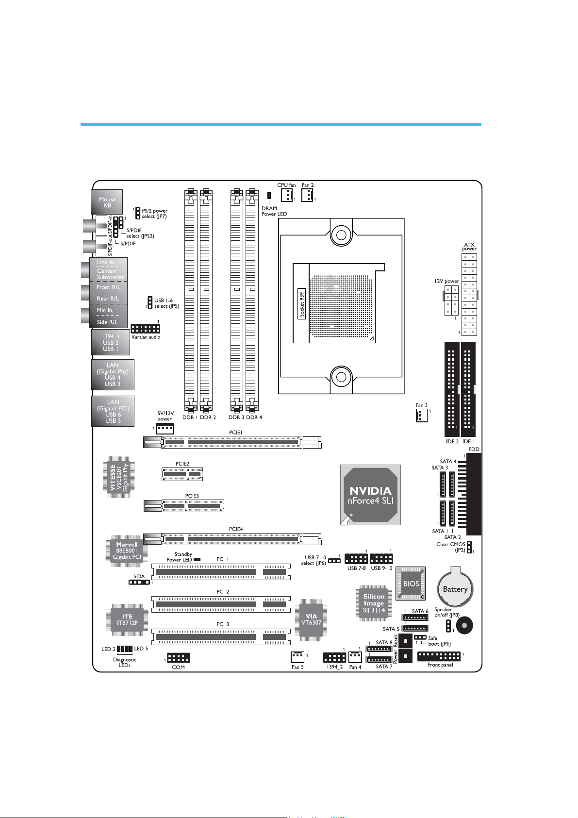
System Board Layout
26
Warning:
.
.
.
.
.
.
.
.
Electrostatic discharge (ESD) can damage your system board,
processor, disk drives, add-in boards, and other components. Perform
the upgrade instruction procedures described at an ESD workstation
only. If such a station is not available, you can provide some ESD
protection by wearing an antistatic wrist strap and attaching it to a
metal part of the system chassis. If a wrist strap is unavailable,
establish and maintain contact with the system chassis throughout
any procedures requiring ESD protection.
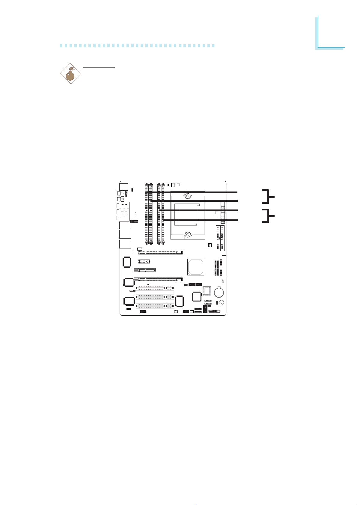
System Memory
Hardware Installation
2
DDR 1
DDR 2
DDR 3
DDR 4
Channel A
Channel B
The system board supports DDR SDRAM DIMM. Double Data
Rate SDRAM (DDR SDRAM) is a type of SDRAM that doubles the
data rate through reading and writing at both the rising and falling
edge of each clock. This effectively doubles the speed of operation
therefore doubling the speed of data transfer.
Refer to chapter 1 (System Memory section) for detailed specification of the memory supported by the system board. The four DDR
DIMM sockets on the system board are divided into 2 channels:
Channel A - DDR 1 and DDR 2
Channel B - DDR 3 and DDR 4
27

2
Hardware Installation
The system board supports the following memory interface.
Single Channel (SC)
Data will be accessed in chunks of 64 bits (8B) from the memory
channels.
Dual Channel (DC)
Data will be accessed in chunks of 128 bits from the memory
channels. Dual channel provides better system performance because
it doubles the data transfer rate.
Single Channel
Dual Channel
BIOS Setting
Configure the system memory in the Genie BIOS Setting submenu
(“DRAM Configuration” section) of the BIOS.
• DIMMs are on the same channel.
• DIMMs in a channel can be identical or
completely different. However, we highly
recommend using identical DIMMs.
• Not all slots need to be populated.
• DIMMs of the same memory configura-
tion are on different channels.
28
Hardware Installation
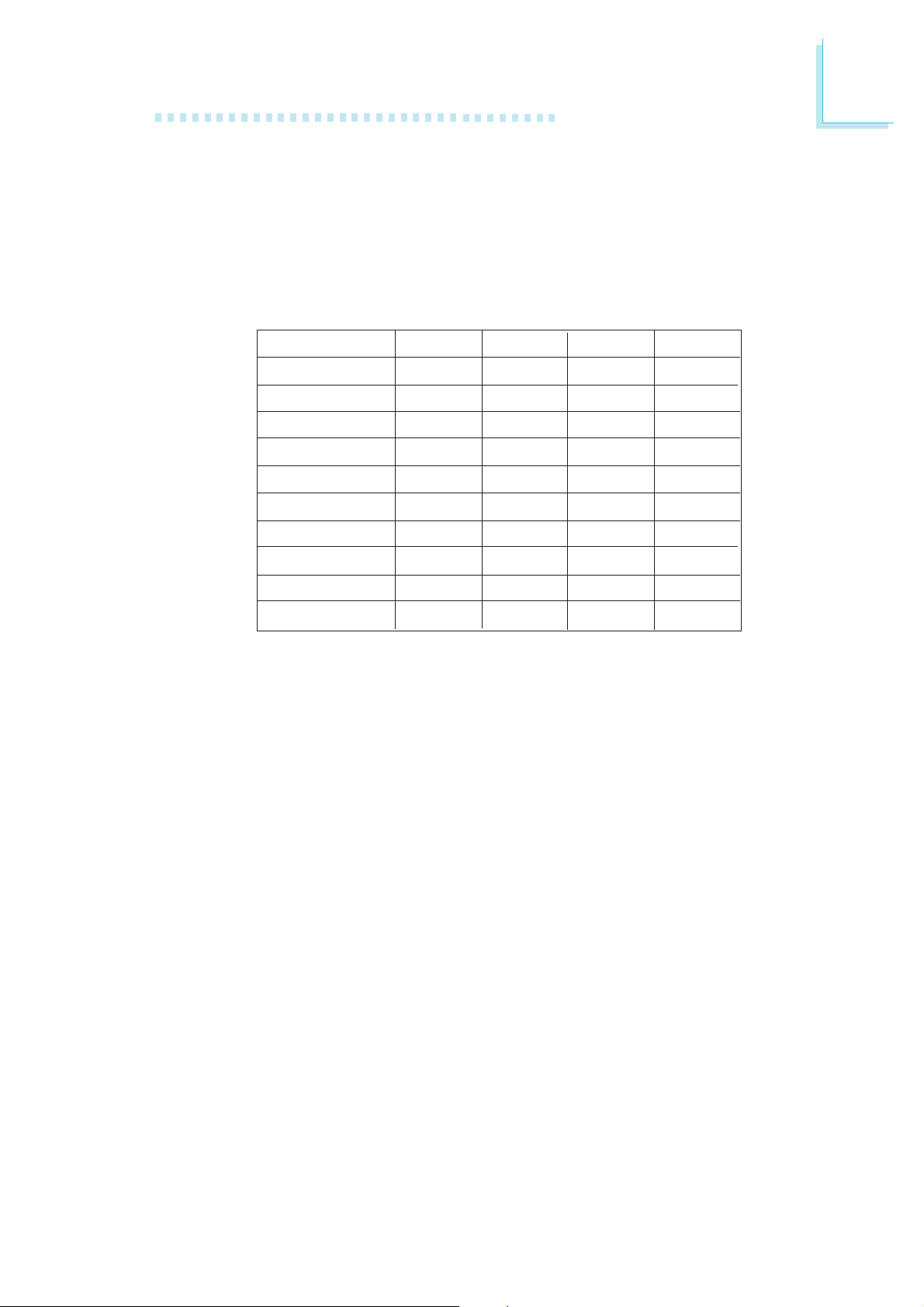
The integrated memory controller in AMD's 64-bit Socket 939
series CPU will directly catch data transmission from DDR RAM
without passing through the Northbridge. Therefore when using 4
identical double side DIMMs or using 2 DIMMs in non-dual channels,
the memory speed will reduce to DDR333. Please refer to the
detailed memory speed shown below.
2
Memory Speed
DDR400
DDR400
DDR400
DDR400
DDR400
DDR400
DDR400
DDR333
DDR400
DDR333
"S": Single side DIMM
"D": Double side DIMM
DIMM 1
S
D
S
D
S
D
S
D
DIMM 2
S
D
S
D
DIMM 3
S
D
S
D
S
D
DIMM 4
S
D
A DIMM's SPD is originally fixed at 1T. When modules are inserted
in DIMM 1 and DIMM 3, the SPD must be 2T for better system
stability. We recommend inserting DIMMs in DIMM 2 and DIMM 4.
29
2
Hardware Installation
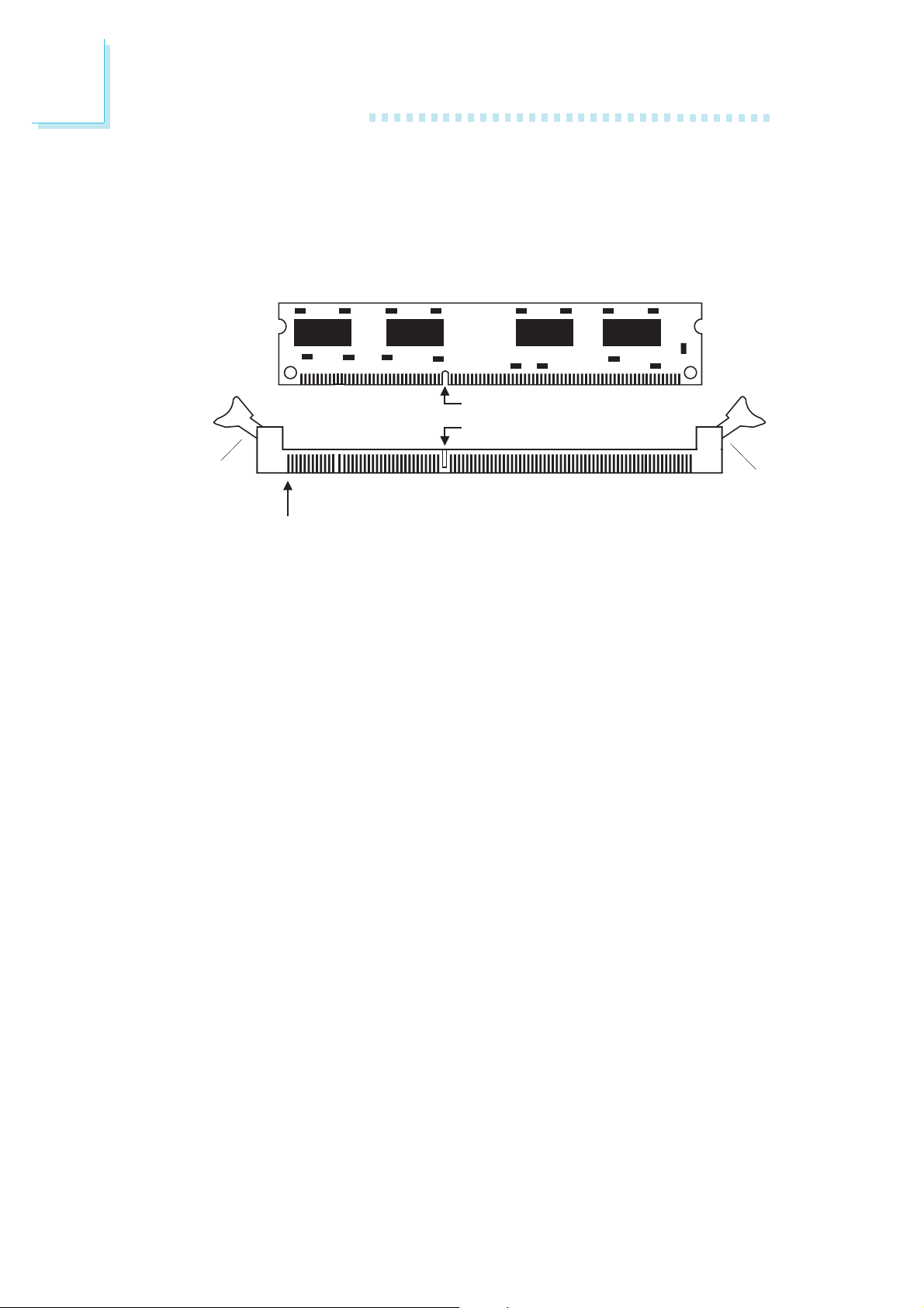
Installing the DIM Module
A DIM module simply snaps into a DIMM socket on the system
board. Pin 1 of the DIM module must correspond with Pin 1 of the
socket.
Notch
Key
Tab
Pin 1
1. Pull the “tabs” which are at the ends of the socket to the side.
2. Position the DIMM above the socket with the “notch” in the
module aligned with the “key” on the socket.
3. Seat the module vertically into the socket. Make sure it is
completely seated. The tabs will hold the DIMM in place.
Tab
30