

LANPARTY UT nF3 250Gb User Guide

System Board
User’s Manual
81000414

Copyright
This publication contains information that is protected by copyright.
No part of it may be reproduced in any form or by any means or
used to make any transformation/adaptation without the prior written permission from the copyright holders.
This publication is provided for informational purposes only. The
manufacturer makes no representations or warranties with respect to
the contents or use of this manual and specifically disclaims any
express or implied warranties of merchantability or fitness for any
particular purpose. The user will assume the entire risk of the use or
the results of the use of this document. Fur ther, the manufacturer
reserves the right to revise this publication and make changes to its
contents at any time, without obligation to notify any person or
entity of such revisions or changes.
© 2004. All Rights Reserved.
Trademarks
Windows® 98, Windows® 98 SE, Windows® ME, Windows® 2000,
Windows NT® 4.0 and Windows® XP are registered trademarks of
Microsoft Corporation. AMD and AthlonTM are registered trademarks
of Advanced Micro Devices, Inc. nVIDIA® is a registered trademark
of NVIDIA Corporation. VIA® is a registered trademark of VIA
Technologies, Inc. Award is a registered trademark of Award
Software, Inc. Other trademarks and registered trademarks of products appearing in this manual are the properties of their respective
holders.
Caution
To avoid damage to the system:
• Use the correct AC input voltage range
To reduce the risk of electric shock:
• Unplug the power cord before removing the system chassis
cover for installation or servicing. After installation or servicing,
cover the system chassis before plugging the power cord.
..
.
..

Battery:
• Danger of explosion if battery incorrectly replaced.
• Replace only with the same or equivalent type recommend
the manufacturer.
• Dispose of used batteries according to the battery manufacturer’s
instructions.
FCC and DOC Statement on Class B
This equipment has been tested and found to comply with the limits
for a Class B digital device, pursuant to Part 15 of the FCC rules.
These limits are designed to provide reasonable protection against
harmful interference when the equipment is operated in a residential
installation. This equipment generates, uses and can radiate radio
frequency energy and, if not installed and used in accordance with
the instruction manual, may cause harmful interference to radio
communications. However, there is no guarantee that interference
will not occur in a particular installation. If this equipment does cause
harmful interference to radio or television reception, which can be
determined by turning the equipment off and on, the user is
encouraged to try to correct the interference by one or more of the
following measures:
by
• Reorient or relocate the receiving antenna.
• Increase the separation between the equipment and the receiver.
• Connect the equipment into an outlet on a circuit different from
that to which the receiver is connected.
• Consult the dealer or an experienced radio TV technician for
help.
Notice:
1. The changes or modifications not expressly approved by the
party responsible for compliance could void the user's authority
to operate the equipment.
2. Shielded interface cables must be used in order to comply with
the emission limits.

About this Manual
This user’s manual contains detailed information about the system
board. If, in some cases, some information doesn’t match those
shown in the multilingual manual, the multilingual manual should always be regarded as the most updated version. The multilingual
manual is included in the system board package.
To view the user’s manual, insert the CD into a CD-ROM drive. The
autorun screen (Mainboard Utility CD) will appear. Click the
“TOOLS” icon then click “Manual” on the main menu.
Notice
The system board and accessories in the package may not come
similar to the information stated in this manual. This may differ in
accordance to the sales region or models in which it was sold. For
more information about the standard package in your region, please
contact your dealer or sales representative.
Warranty to the product does not cover....
1. Warranty does not cover damages or failures that arised from
misuse of the product, inability to use the product, unauthorized
replacement or alteration of components and product
specifications.
2. The warranty is void if the product has been subjected to
physical abuse, improper installation, modification, accidents or
unauthorized repair of the product.
3. Unless otherwise instructed in this user’s manual, the user may
not, under any circumstances, attempt to perform service,
adjustments or repairs on the product, whether in or out of
warranty. It must be returned to the purchase point, factory or
authorized service agency for all such work.
4. We will not be liable for any indirect, special, incidental or
consequencial damages to the product that has been modified
or altered.

Table of Contents
Chapter 1 - Introduction
1.1 Specifications......................................................................................................................
1.2 Special Features of the System Board.....................................................
1.3 Package Checklist.........................................................................................................
Chapter 2 - Hardware Installation
2.1 System Board Layout ...........................................................................................
2.2 System Memory...........................................................................................................
2.3 CPU........................................................................................................................................
2.4 Jumper Settings.............................................................................................................
2.5 Rear Panel I/O Ports..............................................................................................
2.6 I/O Connectors...........................................................................................................
Chapter 3 - Award BIOS Setup Utility
3.1 The Basic Input/Output System.....................................................................
3.2 NVRAID BIOS...............................................................................................................
3.3 Updating the BIOS.....................................................................................................
7
10
15
16
17
20
26
29
40
54
99
100
Chapter 4 - Supported Softwares
4.1 Drivers, Utilities and Software Applications.....................................
4.2 Installation Notes......................................................................................................
102
110

1
Introduction
Appendix A - System Error Messages
A.1 POST Beep........................................................................................................................
A.2 Error Messages...............................................................................................................
Appendix B - Troubleshooting
B.1 Troubleshooting Checklist.....................................................................................
111
111
113
6

Chapter 1 - Introduction
1.1 Specifications
Processor
• AMD AthlonTM 64 (up to 3700+)
• Socket 754
System Bus
• 1600MT/s HyperTransport interface
Chipset
• nVIDIA
System Memory
• Three 184-pin DDR SDRAM DIMM sockets
• Supports single channel (64-bit wide) memory interface
• Supports up to 3GB memory when using DDR333
Supports up to 2GB memory when using DDR400
• Supports PC2700 (DDR333) and PC3200 (DDR400) DDR
SDRAM DIMM
• Supports x8/x16, non-ECC, up to 512Mb DDR devices
• Supports unbuffered DIMM
®
nForce3 250Gb
Introduction
1
BIOS
• Award BIOS
• CPU/DRAM/AGP overclocking
• CPU/DRAM/Chipset overvoltage
• 4Mbit flash memory
• AMD Cool‘n’Quiet
Energy Efficient Design
• Supports ACPI specification and OS Directed Power
Management
• Supports ACPI STR (Suspend to RAM) function
• Wake-On-Events include:
- Wake-On-PS/2 Keyboard/Mouse
- Wake-On-Ring (external modem)
- Wake-On-LAN
- RTC timer to power-on the system
• AC power failure recovery
TM
technology
7

1
Introduction
Hardware Monitor
• Monitors CPU/system temperature
• Monitors 12V/5V/3.3V/Vcore/Vbat/5Vsb/Vchipset/Vdram/Vagp
voltages
• Monitors the speed of the CPU fan, chassis fan and 2nd fan
• CPU Overheat Protection function monitors CPU temperature
during system boot-up
Audio Features
• AC’97 CODEC
• 8 Channels DA Converters with 48KHz rate
• Stereo AD Converters with 48KHz rate
• Microsoft
• S/PDIF-in/out interface
Onboard LAN Features
• Marvell 88E1111 Gigabit PHY
• 10/100/1000BASE-T IEEE 802.3 compliant
®
DirectSound/DirectSound 3D
IDE Interface with NVIDIA RAID
• Two IDE connectors support four UltraDMA 133Mbps hard
drives
• NVIDIA RAID supports spanning across Serial ATA and Parallel
ATA
• RAID 0, RAID 1, RAID 0+1 and JBOD
Serial ATA Interface with NVIDIA RAID
• Four Serial ATA interfaces with speed up to 1.5Gbps
- Two Serial ATA ports supported by nForce3 250Gb chip
- Two Serial ATA ports supported by Marvell SATA PHY
• NVIDIA RAID supports spanning across Serial ATA and Parallel
ATA
• RAID 0, RAID 1, RAID 0+1 and JBOD
IEEE 1394 Interface(Optional)
• VIA VT6307 controller
• Supports two 100/200/400 Mb/sec ports
Accelerated Graphics Port (A.G.P.)
• Supports AGP 8x up to 2132MB/sec. and AGP 4x up to
1066MB/sec. bandwidth for 3D graphics applications
• Supports 0.8/1.5V add-in cards
8

Introduction
Rear Panel I/O Ports
• 1 PS/2 mouse port
• 1 PS/2 keyboard port
• 1 DB-25 parallel por t
• 2 S/PDIF RCA jacks (S/PDIF-in and S/PDIF-out)
• 1 DB-9 serial port
• 1 IEEE 1394 port(Optional)
• 1 RJ45 LAN port
• 4 USB 2.0/1.1 ports
• Line-in, line-out (front R/L) and mic-in jacks
• Center/subwoofer, rear R/L jacks and side R/L
I/O Connectors
• 2 connectors for 4 additional external USB 2.0/1.1 ports
• 1 connector for 1 external IEEE 1394 port(Optional)
• 1 front audio connector for external line-out and mic-in jacks
• 1 CD-in internal audio connector
• 1 S/PDIF connector for optical cable connection
• 1 IrDA connector
• 4 Serial ATA connectors
• 2 IDE connectors
• 1 floppy connector
• 1 20-pin ATX power connector
• 1 4-pin ATX 12V power connector
• 1 front panel connector
• 3 fan connectors
• EZ touch switches (power switch and reset switch)
1
Expansion Slots
• 1 AGP 8x/4x slot
• 5 PCI slots
PCB
• ATX form factor
• 30.5cm (12") x 24cm (9.44")
9

1
Introduction
1.2 Special Features of the System Board
AMD Athlon
The system board supports the AMD Athlon
Athlon
applications by allowing both 32-bit and 64-bit applications to run
simultaneously on the same platform. The operating system and
software are able to process more data and access a tremendous
amount of memory which improves the overall system performance.
2T timing which provides better system stability is supported in CG
or later revisions of the AMD Athlon
the memory timing in the Genie BIOS Setting submenu (“DRAM
Configuration” section) of the BIOS.
AMD Cool‘n’Quiet
The AMD Cool‘n’QuietTM technology allows the system to detect the
CPU’s tasks and utilization status. When the CPU’s task slows down,
the system effectively lowers power consumption by lowering its
CPU speed and voltage, subsequently decreasing its noise level.
TM
TM
64
TM
64 processor. AMD
64 provides superior computing for many software
TM
64 processor. You can select
TM
Technology
CPU Overheat Protection
CPU Overheat Protection has the capability of monitoring the CPU’s
temperature during system boot up. Once the CPU’s temperature
exceeded the temperature limit pre-defined by the CPU, the system
will automatically shutdown. This preventive measure has been added
to protect the CPU from damage and insure a safe computing
environment.
10

Introduction
DDR
DDR (Double Data Rate) is a type of SDRAM that doubles the
data rate through reading and writing at both the rising and falling
edge of each clock. This effectively doubles the speed of operation
therefore providing two times faster data transfer.
Note:
If you are installing more than one double rank DDR400, the
maximum DRAM speed will automatically be limited to the
speed of a DDR333. However, the BIOS provides the option
of manually adjusting the speed to DDR400 by selecting
“200” in the “DRAM Frequency Set (Mhz)” field (Genie BIOS
Setting submenu, DRAM Configuration section) of the BIOS.
S/PDIF
1
S/PDIF is a standard audio file transfer format that transfers digital
audio signals to a device without having to be converted first to an
analog format. This prevents the quality of the audio signal from
degrading whenever it is converted to analog. S/PDIF is usually
found on digital audio equipment such as a DAT machine or audio
processing device. The S/PDIF connector on the system board sends
surround sound and 3D audio signal outputs to amplifiers and
speakers and to digital recording devices like CD recorders.
8-channel Audio
The 6 audio jacks at the rear I/O panel supports 8-channel audio
output.
Serial ATA Interface
Serial ATA is a storage interface that is compliant with SATA 1.0
specification. With speed of up to 1.5Gbps, it improves hard drive
performance faster than the standard parallel ATA.
NVIDIA RAID
NVIDIA RAID supports spanning across Serial ATA and Parallel
ATA. It suppor ts RAID 0, RAID 1, RAID 0+1 and JBOD.
11

1
Introduction
IEEE 1394 Interface(Optional)
IEEE 1394 is fully compliant with the 1394 OHCI (Open Host
Controller Interface) 1.1 specification. It supports up to 63 devices
that can run simultaneously on a system. 1394 is a fast external bus
standard that supports data transfer rates of up to 400Mbps. In
addition to its high speed, it also supports isochronous data transfer
which is ideal for video devices that need to transfer high levels of
data in real-time. 1394 supports both Plug-and-Play and hot
plugging.
IrDA Interface
The system board is equipped with an IrDA connector for wireless
connectivity between your computer and peripheral devices. The
IRDA (Infrared Data Association) specification supports data
transfers of 115K baud at a distance of 1 meter.
USB Ports
The system board supports USB 2.0 and USB 1.1 ports. USB 1.1
supports 12Mb/second bandwidth while USB 2.0 supports 480Mb/
second bandwidth providing a marked improvement in device
transfer speeds between your computer and a wide range of
simultaneously accessible external Plug and Play peripherals.
Dual Function Power Button
Depending on the setting in the “Soft-Off By PBTN” field of the
Power Management Setup, this switch will allow the system to enter
the Soft-Off or Suspend mode.
AGP (Accelerated Graphics Port)
AGP is an interface designed to support high performance 3D
graphics cards. It utilizes a dedicated pipeline to access system
memory for texturing, z-buffering and alpha blending. The AGP slot
supports AGP 8x (0.8V) with up to 2.13GB/sec. bandwidth and
AGP 4x (1.5V) with up to 1066MB/sec. bandwidth for 3D graphics
applications. AGP in this system board will deliver faster and better
graphics to your PC.
12

Introduction
Wake-On-Ring
This feature allows the system that is in the Suspend mode or Soft
Power Off mode to wake-up/power-on to respond to calls coming
from an external modem or respond to calls from a modem PCI
card that uses the PCI PME (Power Management Event) signal to
remotely wake up the PC.
Important:
If you are using a modem add-in card, the 5VSB power source
of your power supply must support a minimum of ≥720mA.
Wake-On-LAN
This feature allows the network to remotely wake up a Soft Power
Down (Soft-Off) PC. It is supported via the onboard LAN port or
via a PCI LAN card that uses the PCI PME (Power Management
Event) signal. However, if your system is in the Suspend mode, you
can power-on the system only through an IRQ or DMA interrupt.
1
Important:
The 5VSB power source of your power supply must support
≥
720mA.
Wake-On-PS/2 Keyboard/Mouse
This function allows you to use the PS/2 keyboard or PS/2 mouse
to power-on the system.
Important:
The 5VSB power source of your power supply must support
≥
720mA.
RTC Timer to Power-on the System
The RTC installed on the system board allows your system to automatically power-on on the set date and time.
AC Power Failure Recovery
When power returns after an AC power failure, you may choose to
either allow the system to power-on automatically or leave the
system in Off state.
13

1
Introduction
ACPI
The system board is designed to meet the ACPI (Advanced Configuration and Power Interface) specification. ACPI has energy saving
features that enables PCs to implement Power Management and
Plug-and-Play with operating systems that support OS Direct Power
Management. Currently, only Windows
the ACPI function allowing you to use the Suspend to RAM function.
With the Suspend to RAM function enabled, you can power-off the
system at once by pressing the power button or selecting “Standby”
when you shut down Windows
go through the sometimes tiresome process of closing files, applications and operating system. This is because the system is capable of
storing all programs and data files during the entire operating session
into RAM (Random Access Memory) when it powers-off. The
operating session will resume exactly where you left off the next time
you power-on the system.
®®
®
®®
98/2000/ME/XP supports
®®
®
®®
98/2000/ME/XP without having to
Important:
The 5VSB power source of your power supply must support
≥
1A.
Virus Protection
Most viruses today destroy data stored in hard drives. The system
board is designed to protect the boot sector and partition table of
your hard disk drive.
14

1.3 Package Checklist
The system board package contains the following items:
; The system board
; A user’s manual
; Two IDE round cables
; One floppy round cable
; Two Serial ATA data cables
; One Serial ATA power cable
; One “nVRAID Driver” diskette
; One I/O shield
; One “Mainboard Utility” CD
If any of these items are missing or damaged, please contact your
dealer or sales representative for assistance.
Introduction
1
15
2
Hardware Installation
Chapter 2 - Hardware Installation
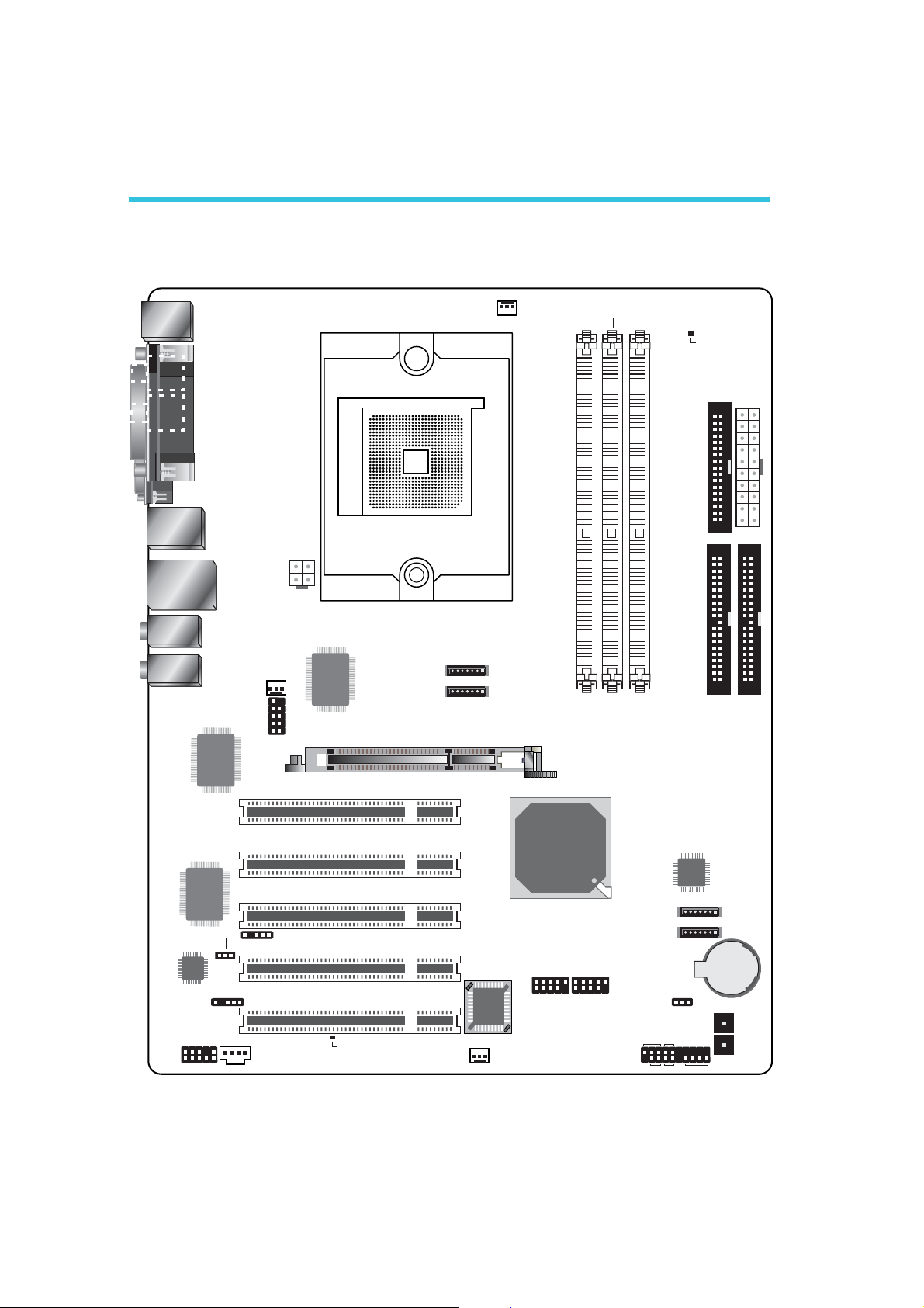
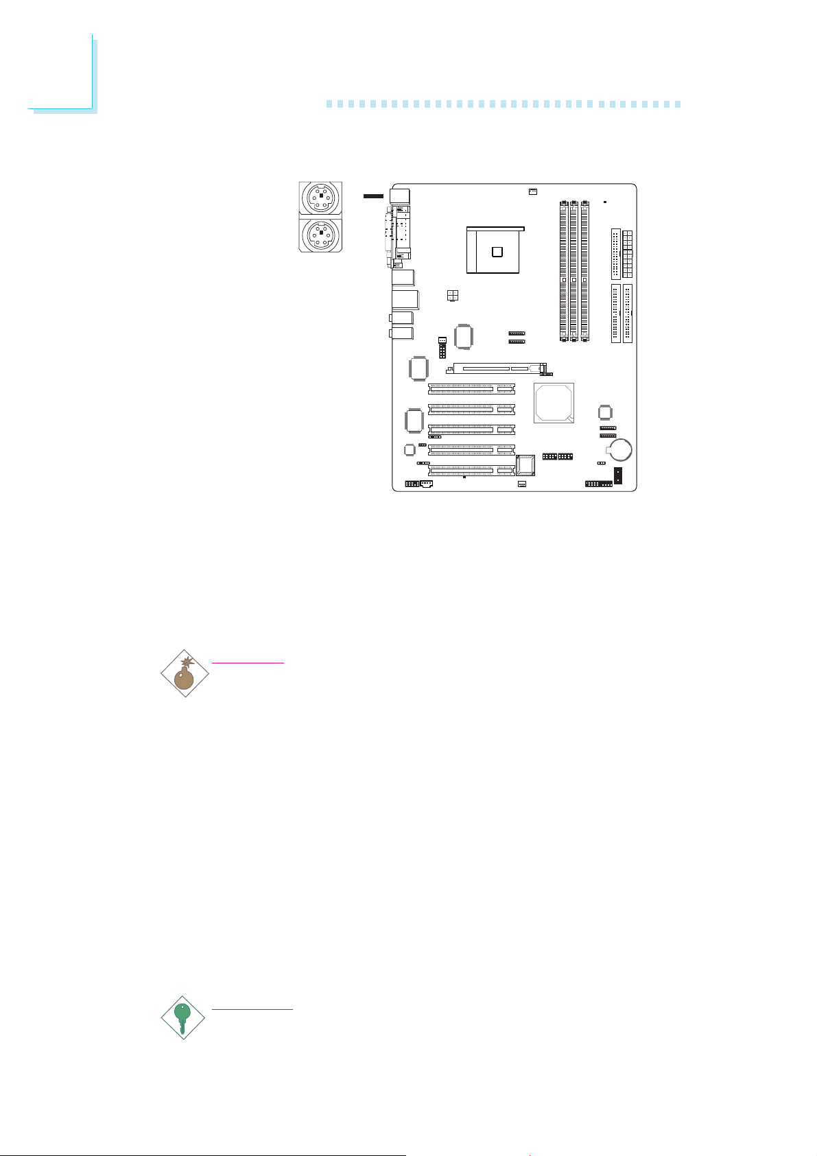
2.1 System Board Layout
S/PDIF-
in
S/PDIF-
out
COM
KB/Mouse
Marvell
88E
IEEE 1394_1,
USB 1-2
LAN,
USB 3-4
Line-in
Front R/L
Mic-in
Center/Subwoofer
Rear R/L
Side R/L
1111
Gigabit
PHY
+12V power
2nd fan
1
IEEE 1394_2
1
CPU fan
DDR 1
DDR 2
DDR 3
DRAM
Power LED
FDD
ATX
power
Socket 754
1
1
1
SATA 3
SATA 4
1
1
1
SEC IDE1PRI IDE
VIA
6307
1
PCI 1
AGP
16
I/O
chip
System beep
select (JP5)
Audio
Codec
1
Front audio
1
1
S/PDIF
CD-in
1
PCI 2
PCI 3
1
IrDA
PCI 4
PCI 5
Standby
Power LED
BIOS
Chassis fan
1
nVIDIA
nForce3-250Gb
USB 5-6 USB 7-8
1 1
SATA 1
SATA 2
1
Clear CMOS (JP2)
ATX-SW
PWR-LED
1
HD-LED
RESET
Marvell
88SR3020
SPEAKER
1
1
Battery
Power
Reset
Warning:
.
.
.
.
.
.
.
.
.
.
.
.
.
.
.
.
Electrostatic discharge (ESD) can damage your system board, processor, disk drives, add-in boards, and other components. Perform the
upgrade instruction procedures described at an ESD workstation only.
If such a station is not available, you can provide some ESD
protection by wearing an antistatic wrist strap and attaching it to a
metal part of the system chassis. If a wrist strap is unavailable,
establish and maintain contact with the system chassis throughout
any procedures requiring ESD protection.
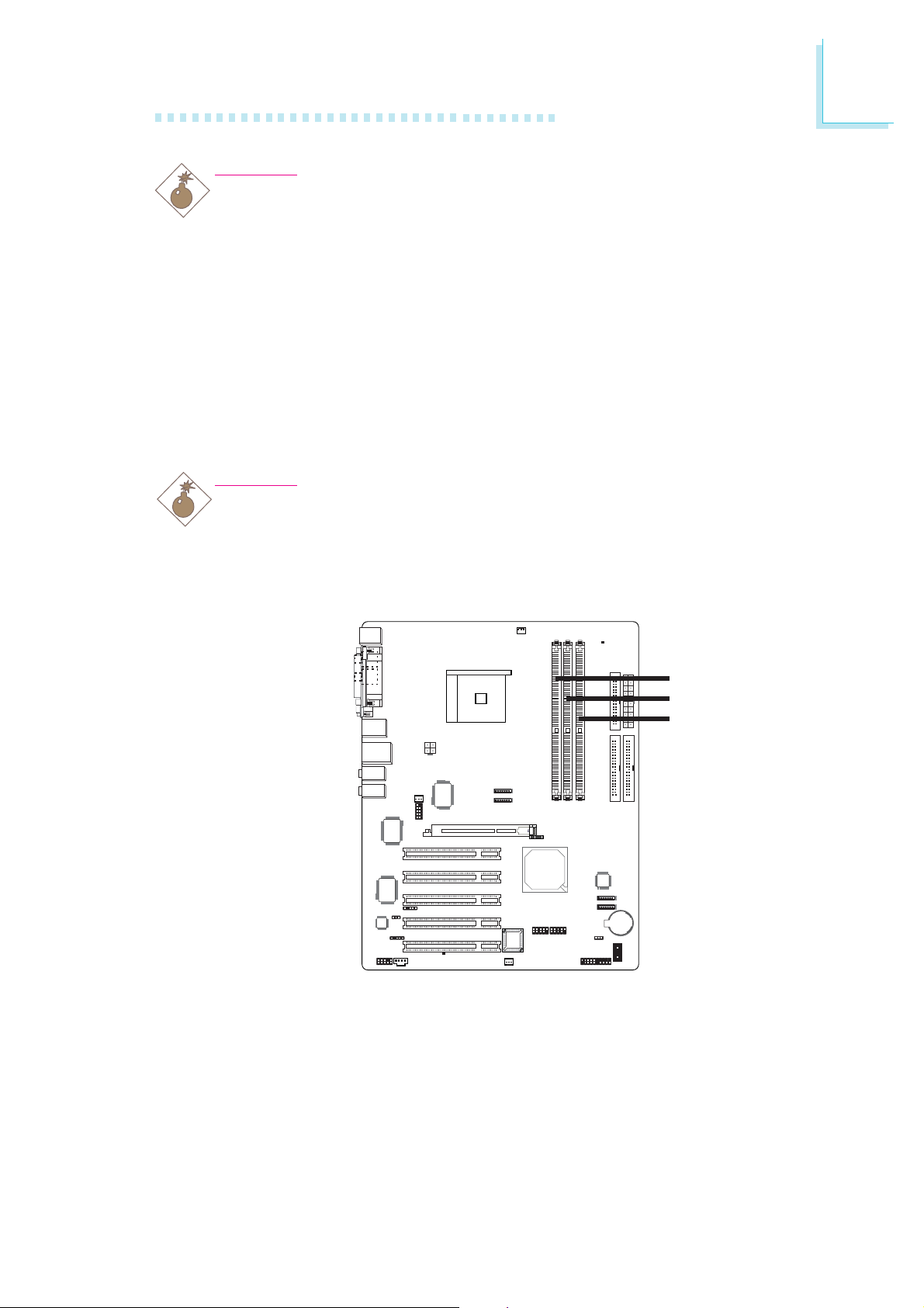
2.2 System Memory
Warning:
When the DRAM Power LED lit red, it indicates that power is
present on the DDR sockets. Power-off the PC then unplug the
power cord prior to installing any memory modules. Failure to do so
will cause severe damage to the motherboard and components.
Hardware Installation
2
DDR 1
DDR 2
DDR 3
The system board supports DDR SDRAM DIMM. Double Data
Rate SDRAM (DDR SDRAM) is a type of SDRAM that doubles the
data rate through reading and writing at both the rising and falling
edge of each clock. This effectively doubles the speed of operation
therefore doubling the speed of data transfer. Refer to chapter 1
(System Memory section) for detailed specification of the memory
supported by the system board.
17
2
Hardware Installation
Maximum system memory:
• Supports up to 3GB memory when using DDR333
• Supports up to 2GB memory when using DDR400
Note:
If you are installing more than one double rank DDR400, the
maximum DRAM speed will automatically be limited to the
speed of a DDR333. However, the BIOS provides the option
of manually adjusting the speed to DDR400 by selecting
“200” in the “DRAM Frequency Set (Mhz)” field (Genie BIOS
Setting submenu, DRAM Configuration section) of the BIOS.
BIOS Setting
Configure the system memory in the Genie BIOS Setting submenu
(“DRAM Configuration” section) of the BIOS.
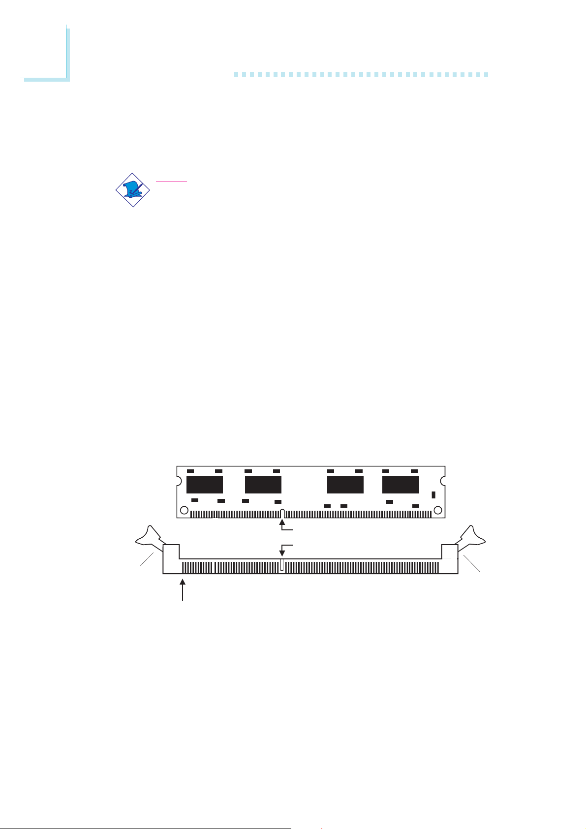
2.2.1 Installing the DIM Module
A DIM module simply snaps into a DIMM socket on the system
board. Pin 1 of the DIM module must correspond with Pin 1 of the
socket.
Tab
Pin 1
1. Pull the “tabs” which are at the ends of the socket to the side.
Notch
Key
Tab
18
2. Position the DIMM above the socket with the “notch” in the
module aligned with the “key” on the socket.
3. Seat the module vertically into the socket. Make sure it is
completely seated. The tabs will hold the DIMM in place.
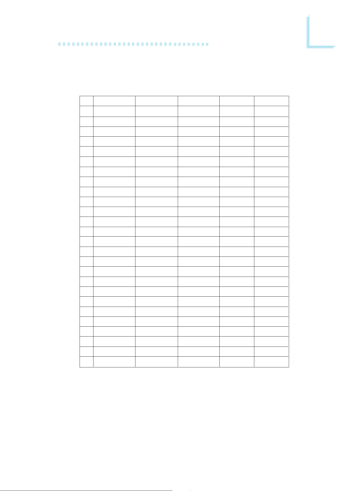
2.2.2 Memory Configuration
Install DDR DIMMs according to the memory configuration below.
Hardware Installation
2
No. DIMM 1
1
single rank
1
empty
1
empty
1
double rank
1
empty
1
empty
2
single rank
2
single rank
2
single rank
2
single rank
2
double rank
2
double rank
2
double rank
2
double rank
2
empty
2
empty
2
empty
2
empty
3
single rank
3
single rank
3
single rank
3
single rank
3
double rank
3
double rank
3
double rank
3
double rank
DIMM 2
empty
single rank
empty
empty
double rank
empty
single rank
double rank
empty
empty
single rank
double rank
empty
empty
single rank
single rank
double rank
double rank
single rank
single rank
double rank
double rank
single rank
single rank
double rank
double rank
DIMM 3 1T 2T
empty
empty
single rank
empty
empty
double rank
empty
empty
single rank
double rank
empty
empty
single rank
double rank
single rank
double rank
single rank
double rank
single rank
double rank
single rank
double rank
single rank
double rank
single rank
double rank
DDR400
DDR400
DDR400
DDR400
DDR400
DDR400
DDR400
DDR400
DDR400
DDR400
DDR400
DDR333
DDR400
DDR333
DDR333
DDR200
DDR200
DDR200
DDR333
DDR200
DDR200
DDR200
DDR333
DDR200
DDR200
DDR200
DDR400
DDR400
DDR400
DDR400
DDR400
DDR400
DDR400
DDR400
DDR400
DDR400
DDR400
DDR333
DDR400
DDR333
DDR400
DDR400
DDR400
DDR333
DDR400
DDR333
DDR333
DDR333
DDR333
DDR333
DDR333
DDR333
19
2
Hardware Installation
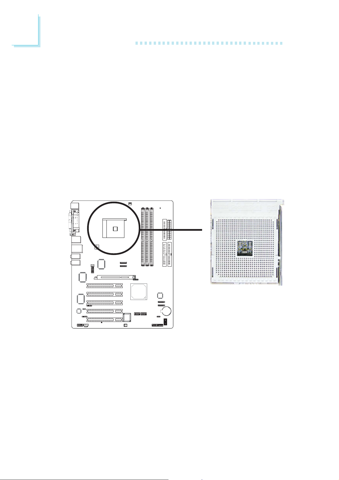
2.3 CPU
2.3.1 Overview
The system board is equipped with a surface mount 754-pin CPU
socket. This socket is exclusively designed for installing an AMD CPU.
2.3.2 Installing the CPU
1. Make sure the PC and all other peripheral devices connected to
it has been powered down.
2. Disconnect all power cords and cables.
3. Locate the 754-pin CPU socket on the system board.
X
20
Hardware Installation
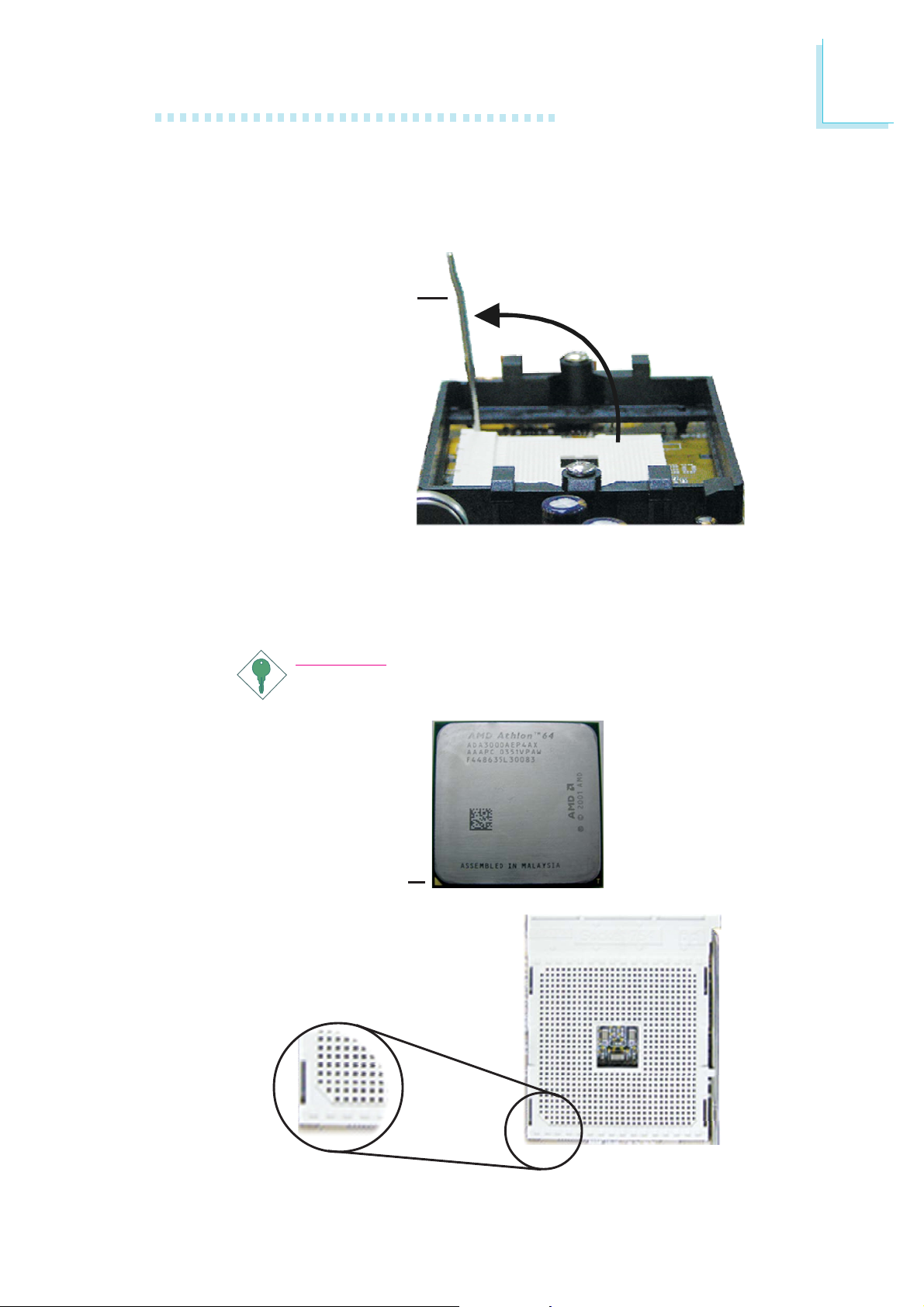
4. Unlock the socket by pushing the lever sideways, away from the
socket, then lifting it up to a 90o angle. Make sure the lever is lifted
to at least this angle otherwise the CPU will not fit in properly.
Lever
2
5. Position the CPU above the socket. The gold mark on the CPU
must align with the corner of the CPU socket (refer to the
enlarged view) shown below.
Important:
Handle the CPU by its edges and avoid touching the pins.
Gold mark
21
2
Hardware Installation
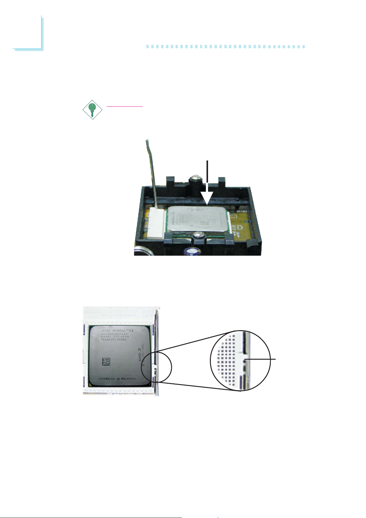
6. Insert the CPU into the socket until it is seated in place. The
CPU will fit in only one orientation and can easily be inserted
without exerting any force.
Important:
Do not force the CPU into the socket. Forcing the CPU into
the socket may bend the pins and damage the CPU.
7. Once the CPU is in place, push down the lever to lock the
socket. The lever should click on the side tab to indicate that the
CPU is completely secured in the socket.
Side tab
22
2.3.3 Installing the Fan and Heat Sink
The CPU must be kept cool by using a CPU fan with heat sink.
Without sufficient air circulation across the CPU and heat sink, the
CPU will overheat damaging both the CPU and system board.
Note:
• Use only certified fan and heat sink.
• The fan and heat sink package usually contains the fan and
heat sink assembly, and an installation guide. If the
installation procedure in the installation guide differs from
the one in this section, please follow the installation guide in
the package.
1. Before you install the fan / heat sink, you must apply a thermal
paste onto the top of the CPU. The thermal paste is usually
supplied when you purchase the CPU or fan heat sink assembly.
Do not spread the paste all over the surface. When you later
place the heat sink on top of the CPU, the compound will
disperse evenly.
Hardware Installation
2
Do not apply the paste if the fan / heat sink already has a patch
of thermal paste on its underside. Peel the strip that covers the
paste before you place the fan / heat sink on top of the CPU.
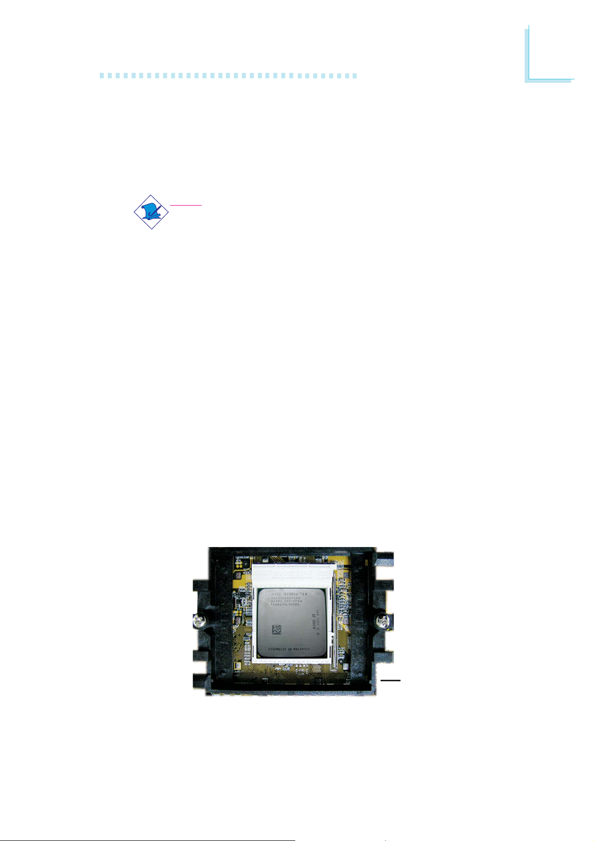
2. The system board comes with the retention module base already
installed.
Retention
module base
23
2
Hardware Installation
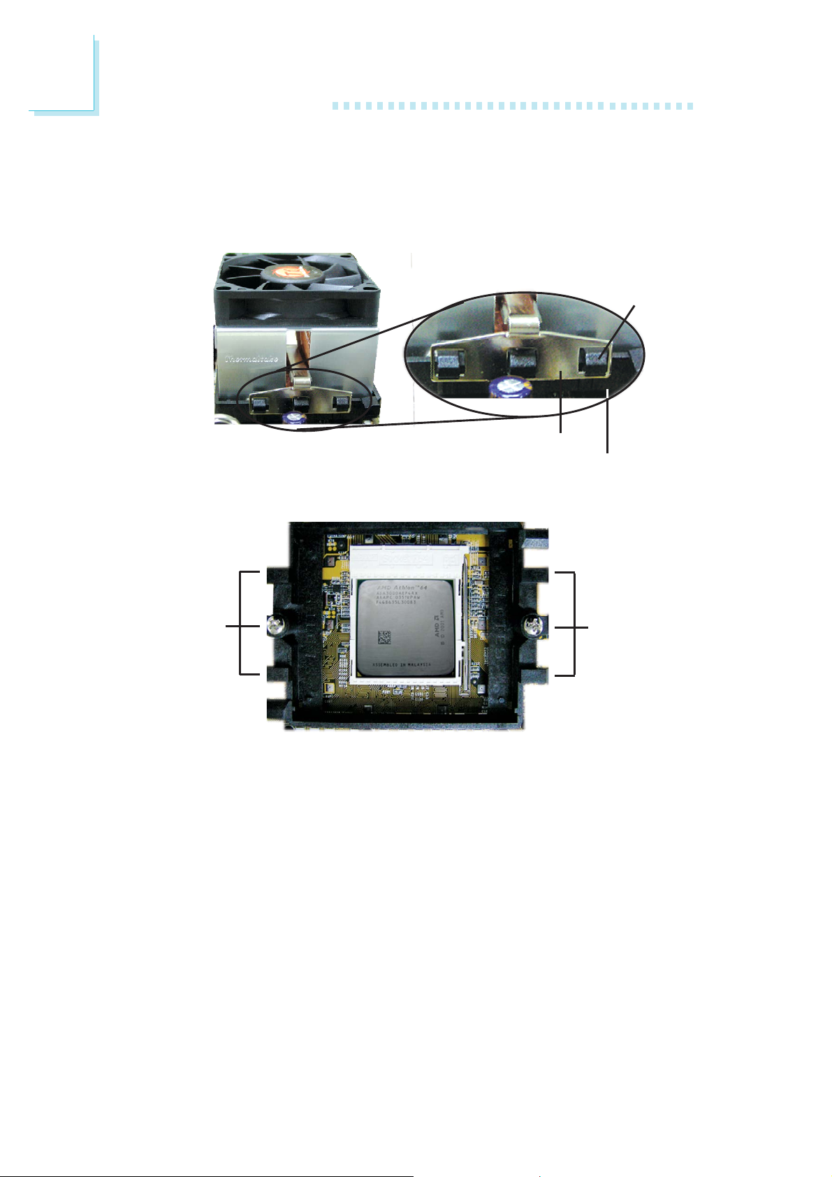
3. Place the heat sink on top of the CPU. Now hook one side of
the retention clip onto the retention module base by fitting the
holes on the retention clip into the retaining tabs of the retention
module base.
Retaining
tab
Retention clip
Retention module base
Side View
Retaining
tabs
Retaining
tabs
Top View
24
Hardware Installation
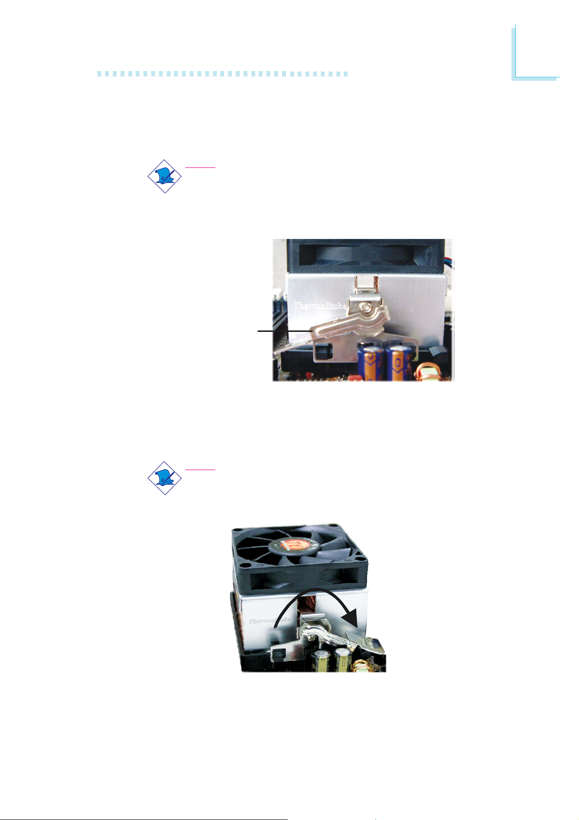
4. Hook the other side of the retention clip (the one near the
retention lever) so that the holes on the retention clip also fit
into the retaining tabs of the retention module base.
Note:
You will not be able to secure the fan and heat sink
assembly in place if it did not fit properly onto the
retention module base.
Retention lever
2
5. Move the retention lever to its opposite side then push it down
to lock the fan and heat sink assembly to the retention module
base.
Note:
Make sure there is sufficient air circulation across the CPU
fan and heat sink.
6. Connect the CPU fan’s cable connector to the CPU fan connector on the system board.
25
2
Hardware Installation
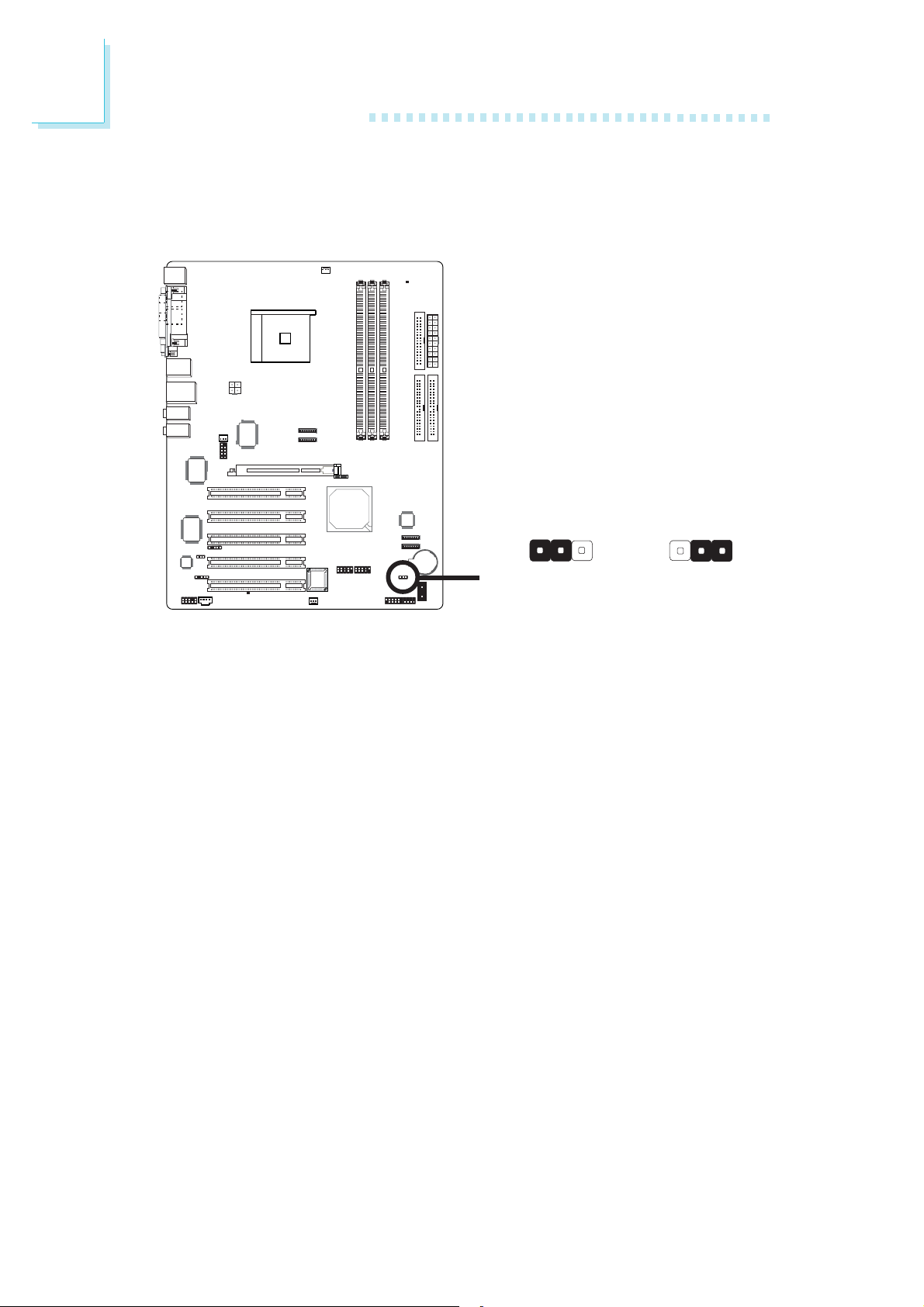
2.4 Jumper Settings
2.4.1 Clear CMOS Data
312312
JP2
If you encounter the following,
a) CMOS data becomes corrupted.
b) You forgot the keyboard, supervisor or user password.
c) You are unable to boot-up the computer system because the
processor’s clock/ratio was incorrectly set in the BIOS.
you can reconfigure the system with the default values stored in the
ROM BIOS.
To load the default values stored in the ROM BIOS, please follow
the steps below.
1. Power-off the system and unplug the power cord.
2. Set JP2 pins 2 and 3 to On. Wait for a few seconds and set JP2
back to its default setting, pins 1 and 2 On.
1-2 On: Normal
X
(default)
2-3 On:
Clear CMOS Data
26
3. Plug the power cord and power-on the system.
If your reason for clearing the CMOS data is due to incorrect
setting of the processor’s clock/ratio in the BIOS, please proceed
to step 4.

Hardware Installation
4. After powering-on the system, press <Del> to enter the main
menu of the BIOS.
5. Select the Genie BIOS Setting submenu and press <Enter>.
6. Set the processor’s clock/ratio to its default setting or an appropriate bus clock or ratio. Refer to the Genie BIOS Setting section
in chapter 3 for more information.
7. Press <Esc> to return to the main menu of the BIOS setup
utility. Select “Save & Exit Setup” and press <Enter>.
8. Type <Y> and press <Enter>.
2
27
2
Hardware Installation
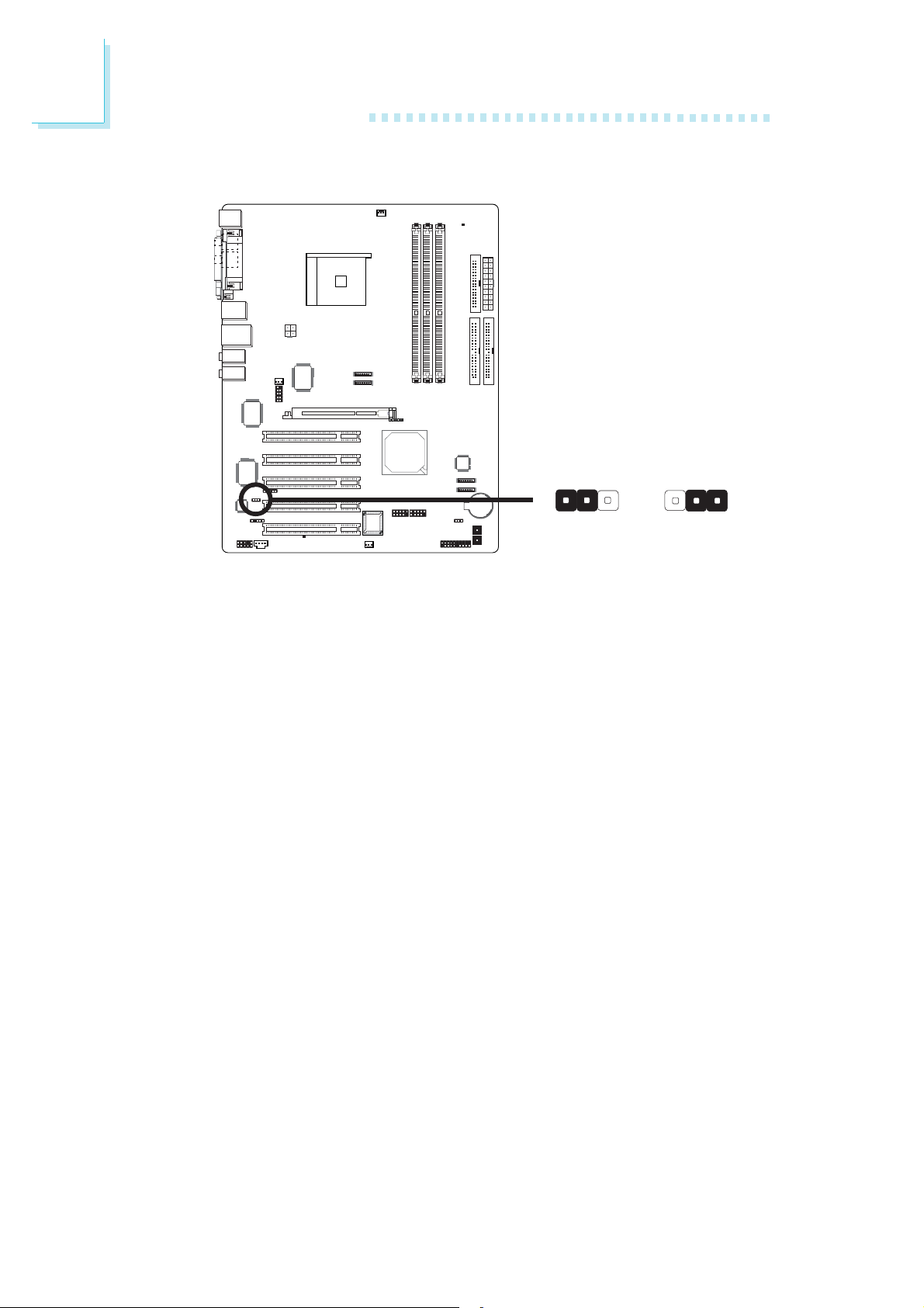
2.4.2 System Beep Select
JP5
312 312
X
1-2 On:
PC Speaker
JP5 is used to select the system’s beep messages and warnings to
come from the line-out (front R/L) jack or the PC speaker.
2-3 On:
Line-out
(Front R/L)
28
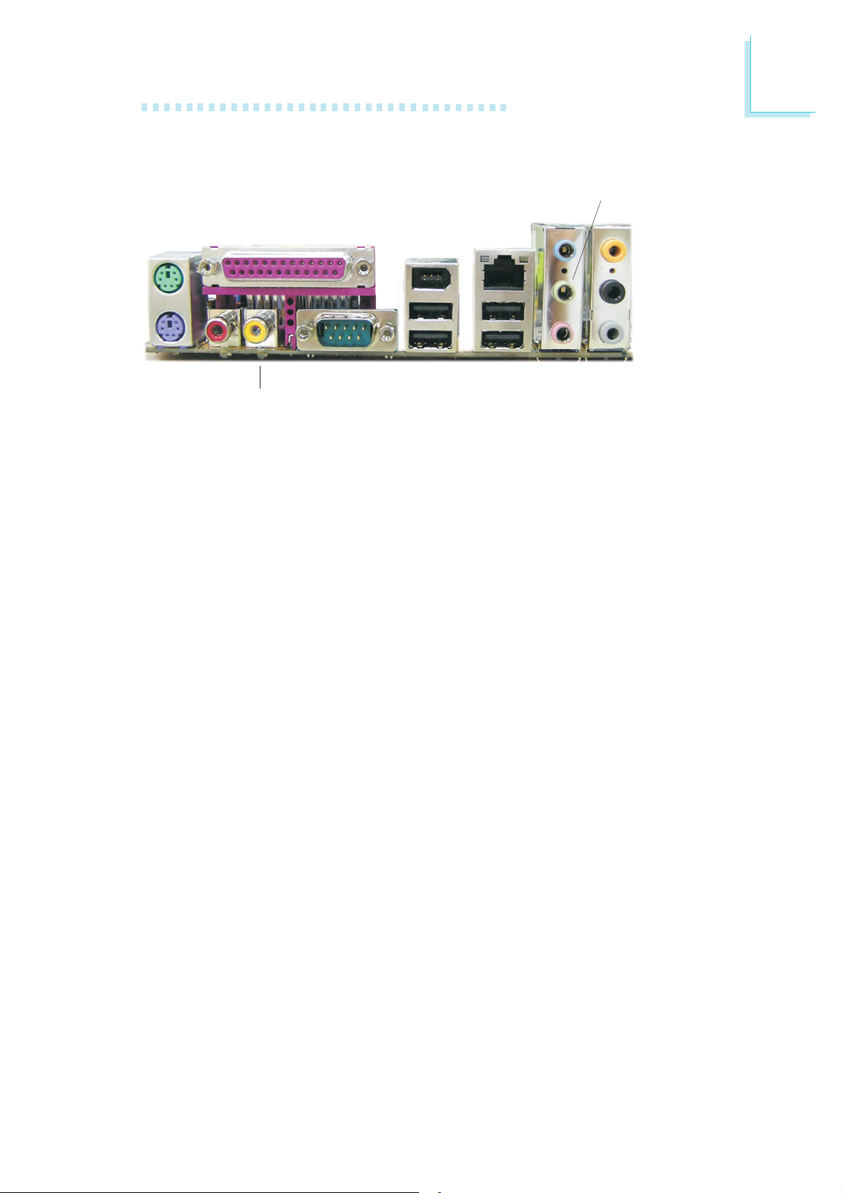
2.5 Rear Panel I/O Ports
PS/2
Mouse
Parallel
IEEE
1394_1
Hardware Installation
Line-out (Front R/L)
RJ45
LAN
Line-in
Center/
Subwoofer
Rear R/L
Side R/L
2
PS/2
K/B
S/PDIF-out
The rear panel I/O ports consist of the following:
• PS/2 mouse port
• PS/2 keyboard port
• Parallel por t
• S/PDIF-in jack
• S/PDIF-out jack
• COM port
• IEEE 1394_1 port (optional)
• USB ports
• LAN port
• Line-in jack
• Line-out (Front right/left) jack
• Mic-in jack
• Center/subwoofer jack
• Rear right/left jack
• Side right/left jack
COMS/PDIF-in
USB 1-2 USB 3-4
Mic-in
29
2
Hardware Installation
2.5.1 PS/2 Mouse and PS/2 Keyboard Ports
PS/2 Mouse
PS/2 Keyboard
W
The system board is equipped with an onboard PS/2 mouse
(Green) and PS/2 keyboard (Purple) ports - both at location CN2
of the system board. The PS/2 mouse port uses IRQ12. If a mouse
is not connected to this port, the system will reserve IRQ12 for
other expansion cards.
.
.
.
.
.
Warning:
.
.
.
Make sure to turn off your computer prior to connecting or
disconnecting a mouse or keyboard. Failure to do so may damage the system board.
Wake-On-PS/2 Keyboard/Mouse
The Wake-On-PS/2 Keyboard/Mouse function allows you to use the
PS/2 keyboard or PS/2 mouse to power-on the system. To use this
function:
• BIOS Setting:
Configure the PS/2 keyboard/mouse wake up function in the
Integrated Peripherals submenu of the BIOS. Refer to chapter 3
for more information.
Important:
The 5VSB power source of your power supply must support
≥
720mA.
30
 Loading...