

LANPARTY UT CFX3200-DR User Guide
System Board
User’s Manual
935-CF3291-000G
90800601

Copyright
This publication contains information that is protected by copyright.
No part of it may be reproduced in any form or by any means or
used to make any transformation/adaptation without the prior
written permission from the copyright holders.
This publication is provided for informational purposes only. The
manufacturer makes no representations or warranties with respect to
the contents or use of this manual and specifically disclaims any
express or implied warranties of merchantability or fitness for any
particular purpose. The user will assume the entire risk of the use or
the results of the use of this document. Further, the manufacturer
reserves the right to revise this publication and make changes to its
contents at any time, without obligation to notify any person or
entity of such revisions or changes.
© 2006. All Rights Reserved.
Trademarks
Product names or trademarks appearing in this manual are for
identification purpose only and are the properties of the respective
owners.

FCC and DOC Statement on Class B
This equipment has been tested and found to comply with the limits
for a Class B digital device, pursuant to Part 15 of the FCC rules.
These limits are designed to provide reasonable protection against
harmful interference when the equipment is operated in a residential
installation. This equipment generates, uses and can radiate radio
frequency energy and, if not installed and used in accordance with
the instruction manual, may cause harmful interference to radio
communications. However, there is no guarantee that interference
will not occur in a particular installation. If this equipment does cause
harmful interference to radio or television reception, which can be
determined by turning the equipment off and on, the user is
encouraged to try to correct the interference by one or more of the
following measures:
• Reorient or relocate the receiving antenna.
• Increase the separation between the equipment and the receiver.
• Connect the equipment into an outlet on a circuit different from
that to which the receiver is connected.
• Consult the dealer or an experienced radio TV technician for
help.
Notice:
1. The changes or modifications not expressly approved by the
party responsible for compliance could void the user's authority
to operate the equipment.
2. Shielded interface cables must be used in order to comply with
the emission limits.

Table of Contents
About this Manual................................................................................
Warranty.....................................................................................................
Static Electricity Precaution................................................................
Safety Measures.....................................................................................
About the Package...............................................................................
Before Using the System Board.........................................................
Chapter 1 - Introduction....................................................................
Specifications...................................................................................................................................
Features..............................................................................................................................................
Français................................................................................................................................................
Deutsch...............................................................................................................................................
Español................................................................................................................................................
Русский язык.........................................................................................................................
Japanese.............................................................................................................................................
Chapter 2 - Hardware Installation....................................................
System Board Layout ..........................................................................................................
System Memory..........................................................................................................................
CPU.......................................................................................................................................................
Jumper Settings............................................................................................................................
Rear Panel I/O Ports.............................................................................................................
Internal I/O Connectors.....................................................................................................
5
5
6
6
7
7
8
8
10
15
17
19
21
23
25
25
26
30
36
41
52
Chapter 3 - BIOS Setup......................................................................
Award BIOS Setup Utility.................................................................................................
RAID BIOS.....................................................................................................................................
Updating the BIOS..................................................................................................................
Chapter 4 - Supported Softwares.....................................................
Chapter 5 - Cool’n’Quiet Technology..............................................
Chapter 6 - RAID.................................................................................
Chapter 7 - ATI CrossFire Technology.............................................
Appendix A - System Error Message...............................................
Appendix B - Troubleshooting..........................................................
70
70
127
128
130
150
153
161
168
170

About this Manual
An electronic file of this manual is included in the CD. To view the
user’s manual, insert the CD into a CD-ROM drive. The autorun
screen (Mainboard Utility CD) will appear. Click the “TOOLS” icon
then click “Manual” on the main menu.
Warranty
1. Warranty does not cover damages or failures that arised from
misuse of the product, inability to use the product, unauthorized
replacement or alteration of components and product
specifications.
2. The warranty is void if the product has been subjected to
physical abuse, improper installation, modification, accidents or
unauthorized repair of the product.
3. Unless otherwise instructed in this user’s manual, the user may
not, under any circumstances, attempt to perform service,
adjustments or repairs on the product, whether in or out of
warranty. It must be returned to the purchase point, factory or
authorized service agency for all such work.
4. We will not be liable for any indirect, special, incidental or
consequencial damages to the product that has been modified
or altered.

1
Introduction
Static Electricity Precautions
It is quite easy to inadvertently damage your PC, system board,
components or devices even before installing them in your system
unit. Static electrical discharge can damage computer components
without causing any signs of physical damage. You must take extra
care in handling them to ensure against electrostatic build-up.
1. To prevent electrostatic build-up, leave the system board in its
anti-static bag until you are ready to install it.
2. Wear an antistatic wrist strap.
3. Do all preparation work on a static-free surface.
4. Hold the device only by its edges. Be careful not to touch any of
the components, contacts or connections.
5. Avoid touching the pins or contacts on all modules and
connectors. Hold modules or connectors by their ends.
Important:
Electrostatic discharge (ESD) can damage your processor, disk
drive and other components. Perform the upgrade instruction
procedures described at an ESD workstation only. If such a
station is not available, you can provide some ESD protection
by wearing an antistatic wrist strap and attaching it to a metal
part of the system chassis. If a wrist strap is unavailable,
establish and maintain contact with the system chassis
throughout any procedures requiring ESD protection.
Safety Measures
To avoid damage to the system:
• Use the correct AC input voltage range
To reduce the risk of electric shock:
• Unplug the power cord before removing the system chassis
cover for installation or servicing. After installation or servicing,
cover the system chassis before plugging the power cord.
..
.
..
Battery:
• Danger of explosion if battery incorrectly replaced.
• Replace only with the same or equivalent type recommend
the manufacturer.
• Dispose of used batteries according to the battery
manufacturer’s
instructions.
by
6

About the Package
The system board package contains the following items. If any of
these items are missing or damaged, please contact your dealer or
sales representative for assistance.
; One system board
; One Karajan audio module
; Two IDE round cables
; One floppy round cable
; Four Serial ATA data cables
; Two Serial ATA power cables
; One I/O shield
; One RAID driver diskette
; One “Mainboard Utility” CD
; One user’s manual
; One Quick Installation Guide
Introduction
1
The system board and accessories in the package may not come
similar to the information listed above. This may differ in accordance
to the sales region or models in which it was sold. For more
information about the standard package in your region, please
contact your dealer or sales representative.
Before Using the System Board
Before using the system board, prepare basic system components.
If you are installing the system board in a new system, you will need
at least the following internal components.
• A CPU
• Memory module
• Storage devices such as hard disk drive, CD-ROM, etc.
You will also need external system peripherals you intend to use
which will normally include at least a keyboard, a mouse and a video
display monitor.
7

1
Introduction
Chapter 1 - Introduction
Specifications
Processor
Front Side Bus
Chipset
System Memory
Expansion Slots
BIOS
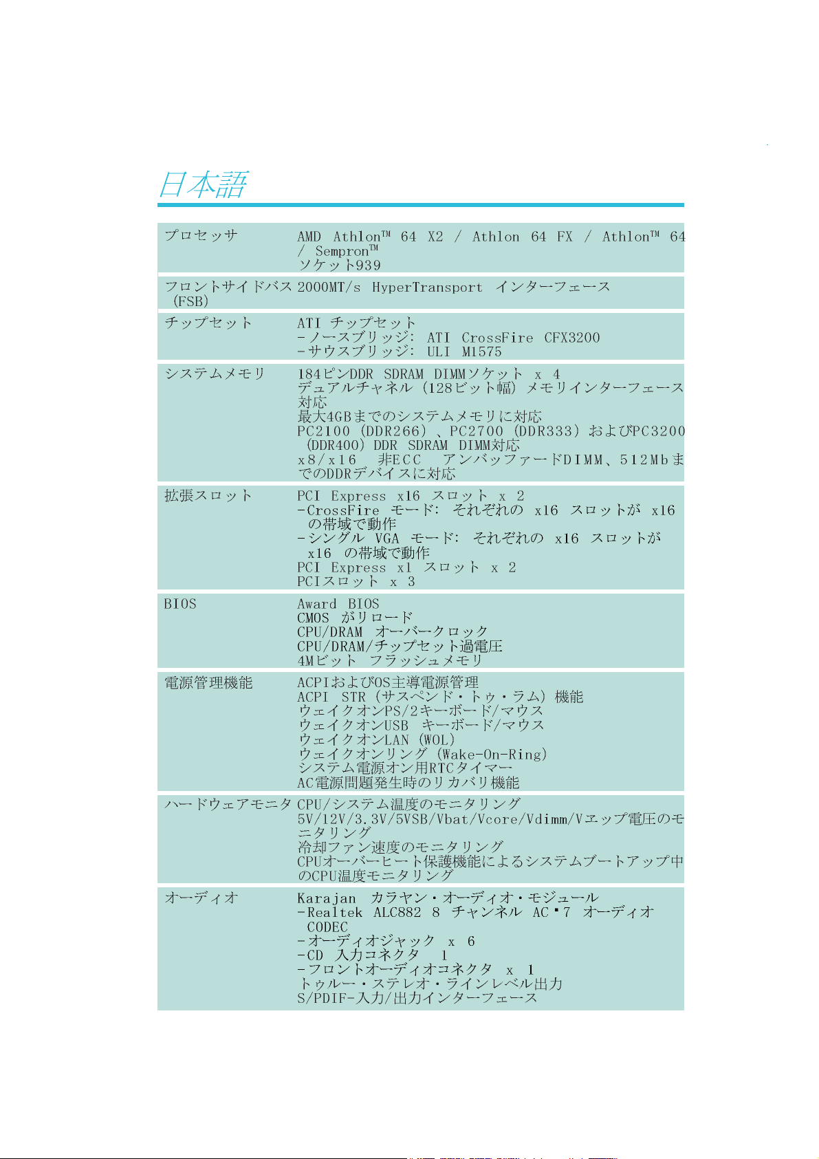
AMD® AthlonTM 64 X2 / Athlon 64 FX / AthlonTM 64 / Sempron
Socket 939
2000MT/s HyperTransport interface
ATI chipset
- Northbridge: ATI CrossFire CFX3200
- Southbridge: ULI M1575
Four 184-pin DDR SDRAM DIMM sockets
Supports dual channel (128-bit wide) memory interface
Supports up to 4GB system memory
Supports PC2100 (DDR266), PC2700 (DDR333) and PC3200
(DDR400) DDR SDRAM DIMM
Supports x8/x16 non-ECC unbuffered DIMMs, up to 512Mb
DDR devices
2 PCI Express x16 slots
- CrossFire mode: Each x16 slot operates at x16 bandwidth.
- Single VGA mode: Each x16 slot operates at x16 bandwidth.
2 PCI Express x1 slots
3 PCI slots
Award BIOS
CMOS Reloaded
CPU/DRAM overclocking
CPU/DRAM/Chipset overvoltage
4Mbit flash memory
TM
Power Management
Hardware Monitor
Audio
ACPI and OS Directed Power Management
ACPI STR (Suspend to RAM) function
Wake-On-PS/2 Keyboard/Mouse
Wake-On-USB Keyboard/Mouse
Wake-On-Ring
Wake-On-LAN
RTC timer to power-on the system
AC power failure recovery
Monitors CPU/system/chipset temperature
Monitors 12V/5V/3.3V/Vcore/Vbat/5Vsb/Vdimm/Vchip voltages
Monitors the speed of the cooling fans
CPU Overheat Protection function monitors CPU temperature
during system boot-up
Karajan audio module
- Realtek ALC882 8-channel High Definition Audio CODEC
- 6 audio jacks
- 1 CD-in connector
- 1 front audio connector
True stereo line level outputs
S/PDIF-in/out interface
8

Introduction
1
LAN
IDE
Serial ATA with
RAID
IEEE 1394
Rear Panel I/O
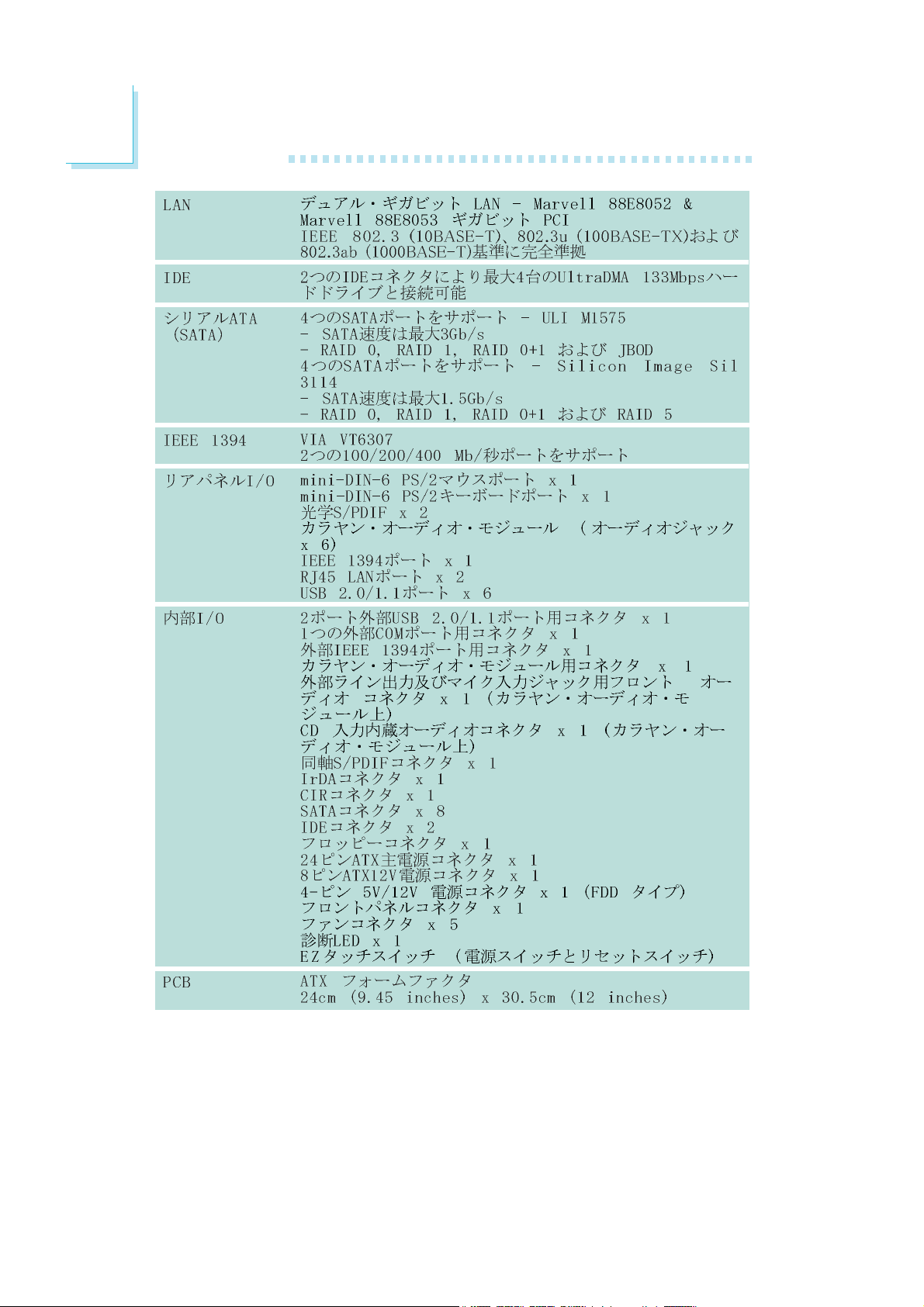
Dual Gigabit LAN - Marvell 88E8052 and Marvell 88E8053
Gigabit PCI LAN
Fully compliant to IEEE 802.3 (10BASE-T), 802.3u (100BASETX) and 802.3ab (1000BASE-T) standards
Supports two IDE connectors that allows connecting up to four
UltraDMA 133Mbps hard drives
Four Serial ATA ports supported by the ULI M1575 chip
- SATA speed up to 3Gb/s
- RAID 0, RAID 1, RAID 0+1 and JBOD
Four Serial ATA ports supported by the Silicon Image Sil 3114
chip
- SATA speed up to 1.5Gb/s
- RAID 0, RAID 1, RAID 0+1 and RAID 5
VIA VT6307
Supports two 100/200/400 Mb/sec ports
1 mini-DIN-6 PS/2 mouse port
1 mini-DIN-6 PS/2 keyboard port
2 S/PDIF RCA jacks (S/PDIF-in and S/PDIF-out)
Karajan audio module (6 audio jacks)
1 IEEE 1394 port
2 RJ45 LAN ports
6 USB 2.0/1.1 ports
Internal I/O
PCB
1 connector for 2 additional external USB 2.0/1.1 ports
1 connector for 1 external IEEE 1394 port
1 connector for 1 external serial port
1 connector for the Karajan audio module
1 front audio connector for external line-out and mic-in jacks
(on the Karajan audio module)
1 CD-in internal audio connector (on the Karajan audio module)
1 S/PDIF connector for optical cable connection
1 IrDA connector
1 CIR connector
8 Serial ATA connectors
2 IDE connectors
o
floppy connector
1 90
1 24-pin ATX power connector
1 8-pin ATX 12V power connector
1 4-pin 5V/12V power connector (FDD type)
1 front panel connector
5 fan connectors
1 Debug LED
EZ touch switches (power switch and reset switch)
ATX form factor
24cm (9.45") x 30.5cm (12")
9
1
Introduction
Features
applications by allowing both 32-bit and 64-bit applications to run
simultaneously on the same platform. The operating system and
software are able to process more data and access a tremendous
amount of memory which improves the overall system performance.
2T timing which provides better system stability is supported in CG
or later revisions of the AMD Athlon
the memory timing in the Genie BIOS Setting submenu (“DRAM
Configuration” section) of the BIOS.
The system board supports the AMD
Athlon
Athlon
computing for many software
TM
64 processor. AMD
TM
64 provides superior
TM
64 processor. You can select
The AMD Cool‘n’QuietTM technology allows
Cool‘n’Quiet
utilization status. When the CPU’s task slows down, the system
effectively lowers power consumption by lowering its CPU speed
and voltage, subsequently decreasing its noise level.
graphics card and a standard PCI Express graphics card, the power
of these multiple GPUs (Graphics Processing Units) within the system
will accelerate your gaming performance and improve image quality.
the physical layer of x1 and x16 lane widths. The x1 PCI Express
lane supports transfer rate of 2.5 Gigabytes (250MBbps) per
second. The PCI Express architecture also provides a high
performance graphics infrastructure by enhancing the capability of a
x16 PCI Express lane to provide 4 Gigabytes per second transfer
rate.
TM
the system to detect the CPU’s tasks and
ATI’s CrossFire
PC to a new peak of performance. By
connecting a Radeon CrossFire Edition
PCI Express is a high bandwidth I/O infrastructure
that possesses the ability to scale speeds by forming
multiple lanes. The system board currently supports
TM
technology drives your
10
Introduction
1
CPU
Overheat
Protection
temperature limit pre-defined by the CPU, the system will automatically
shutdown. This preventive measure has been added to protect the
CPU from damage and insure a safe computing environment.
doubling the speed of data transfer.
able to conveniently switch between these settings simultaneously.
CPU Overheat Protection has the capability of
monitoring the CPU’s temperature during system boot
up. Once the CPU’s temperature exceeded the
Double Data Rate SDRAM (DDR SDRAM) is a type of
SDRAM that doubles the data rate through reading and
writing at both the rising and falling edge of each clock.
This effectively doubles the speed of operation therefore
CMOS Reloaded is a technology that allows storing
multiple user-defined BIOS settings by using the
BIOS utility to save, load and name the settings. This
is especially useful to overclockers who require
saving a variety of overclocked settings and being
The Karajan audio module at the rear I/O panel has 6
audio jacks that provide 8-channel audio output for
advanced 7.1-channel super surround sound audio
system. It is also equipped with a CD-in and front audio
connector.
S/PDIF is a standard audio file transfer format that
transfers digital audio signals to a device without having
to be converted first to an analog format. This prevents
the quality of the audio signal from degrading whenever
it is converted to analog. S/PDIF is usually found on digital audio
equipment such as a DAT machine or audio processing device. The
S/PDIF connector on the system board sends surround sound and
3D audio signal outputs to amplifiers and speakers and to digital
recording devices like CD recorders.
11
1
Introduction
Serial ATA is a storage interface
that is compliant with SATA 1.0
specification. ULI M1575 supports 4 Serial ATA ports
with speed of up to 3Gb/s which is twice as fast as the
standard 1.5Gb/s speed supported by Silicon Image that controls
another 4 Serial ATA ports. Serial ATA it improves hard drive
performance faster than the standard parallel ATA whose data
transfer rate is 100MB/s.
The ULI M1575 chip allows configuring RAID on 4 Serial
ATA drives. It supports RAID 0, RAID 1, RAID 0+1 and
JBOD.
The Silicon Image Sil 3114 chip allows configuring RAID
on another 4 Serial ATA ports. It supports RAID 0, RAID
1, RAID 0+1 and RAID 5.
The Marvell 88E8052 and Marvell 88E8053 Gigabit PCI
LAN support up to 1Gbps.
IEEE 1394 is fully compliant with the 1394 OHCI (Open
Host Controller Interface) 1.1 specification. It supports up
to 63 devices that can run simultaneously on a system.
1394 is a fast external bus standard that supports data
transfer rates of up to 400Mbps. In addition to its high speed, it
also supports isochronous data transfer which is ideal for video
devices that need to transfer high levels of data in real-time. 1394
supports both Plug-and-Play and hot plugging.
IrDA
peripheral devices. The IRDA (Infrared Data Association) specification
supports data transfers of 115K baud at a distance of 1 meter.
The system board is equipped with an IrDA connector
for wireless connectivity between your computer and
12

Introduction
The system board supports USB 2.0 and USB 1.1
ports. USB 1.1 supports 12Mb/second bandwidth while
USB 2.0 supports 480Mb/second bandwidth providing
a marked improvement in device transfer speeds
between your computer and a wide range of simultaneously
accessible external Plug and Play peripherals.
1
W ake-On-ring
wake-up/power-on to respond to calls coming from an external
modem or respond to calls from a modem PCI card that uses the
PCI PME (Power Management Event) signal to remotely wake up
the PC.
Important:
If you are using a modem add-in card, the 5VSB power source
of your power supply must support a minimum of ≥720mA.
W ake-On-L AN
It is supported via the onboard LAN port or via a PCI LAN card
that uses the PCI PME (Power Management Event) signal. However,
if your system is in the Suspend mode, you can power-on the system
only through an IRQ or DMA interrupt.
Important:
The 5VSB power source of your power supply must support
≥
720mA.
This feature allows the system that is in the
Suspend mode or Soft Power Off mode to
This feature allows the network to remotely
wake up a Soft Power Down (Soft-Off) PC.
Wake-On-PS/2
system.
Important:
The 5VSB power source of your power supply must support
≥
720mA.
This function allows you to use the PS/2
keyboard or PS/2 mouse to power-on the
13
1
Introduction
W ake-On-USB
from the S3 (STR - Suspend To RAM) state.
Important:
If you are using the Wake-On-USB Keyboard/Mouse function for
2 USB ports, the 5VSB power source of your power supply
must support ≥1.5A. For 3 or more USB ports, the 5VSB
power source of your power supply must support ≥2A.
ACPI
specification. ACPI has energy saving features that enables PCs to
implement Power Management and Plug-and-Play with operating
systems that support OS Direct Power Management. Currently, only
Windows
enabled in the Power Management Setup will allow you to use the
Suspend to RAM function.
The system board is designed to meet the ACPI
(Advanced Configuration and Power Interface)
®®
®
®®
2000/XP supports the ACPI function. ACPI when
This function allows you to use a USB keyboard or USB mouse to wake up a system
With the Suspend to RAM function enabled, you can power-off the
system at once by pressing the power button or selecting “Standby”
®®
®
when you shut down Windows
through the sometimes tiresome process of closing files, applications
and operating system. This is because the system is capable of
storing all programs and data files during the entire operating session
into RAM (Random Access Memory) when it powers-off. The
operating session will resume exactly where you left off the next time
you power-on the system.
Important:
The 5VSB power source of your power supply must support
≥
1A.
®®
2000/XP without having to go
14

Français
Caractéristiques et Spécifications
Introduction
1
Processeur
Chipset
Mémoire Système
Logements
d’Extension
BIOS
AMD® AthlonTM 64 X2 / Athlon 64 FX / AthlonTM 64 / Sempron
Socket 939
Interface HyperTransport 2000MT/s
®
chipset
ATI
- Pont nord: ATI CrossFire CFX3200
- Pont sud: ULI M1575
4 sockets DDR SDRAM DIMM 184 broches
Supporte l’interface de mémoire deux canaux (128-bit)
Supporte jusqu’à 4GB de mémoire
Supporte DDR SDRAM DIMM PC2100 (DDR266), PC2700
(DDR333) et PC3200 (DDR400)
Supporte exclusivement les modules DIMM non-ECC x8/x16,
densité de RAM jusqu’à 512Mb, DIMM non-tamponnés
2 slots PCI Express x16
- Mode CrossFire: Chaque slot x16 fonctionne à la bande
passante x16.
- Mode Single VGA: Chaque slot x16 fonctionne à la bande
passante x16.
2 slots PCI Express x1
3 slots PCI
Compatible avec Award BIOS
CMOS Reloaded
Overclocking de CPU/DRAM
Contrôle du voltage de CPU/DRAM/Chipset
Mémoire Flash 4Mbit
TM
Gestion de
Puissance
Fonctions de
Moniteur de
Matériel
ACPI et OS Directed Power Management
ACPI STR (Suspend to RAM) fonction
Réveil-Sur-PS/2 Clavier/Souris
Réveil-Sur-USB Clavier/Souris
Eveil Sonnerie
Réveil Par Le Réseau
Minuterie RTC pour allumer le système
Récupération après Défaillance d’Alimentation CA
Gère l’alarme de température et de surchauffe de CPU/système/
chipset
Gère l’alarme de voltage et d’échec de 12V/5V/3.3V/Vcore/
Vbat/5Vsb/Vdimm/Vchip
Gère la vitesse de ventilateur du ventilateur
Protection du CPU - supporte la mise hors circuit automatique
en cas de surchauffage du système
15

1
Introduction
Audio
LAN
IDE
Serial ATA avec
RAID
IEEE 1394
Panneau Arrière
Karajan carte audio
- Audio CODEC Realtek ALC882 8-canaux Définition Élevée
- 6 prises audio
- 1 connecteur CD-in
- 1 connecteur audio de l’avant
Sorties de niveau de lignes stéréo vraies
Interface entrée/sortie S/PDIF
Deux Gigabit LAN - Marvell 88E8052 et Marvell 88E8053
Gigabit PCI LAN
Supporte IEEE 802.3 (10BASE-T), 802.3u (100BASE-TX) et
802.3ab (1000BASE-T)
Supporte des disques durs jusqu’à UltraDMA 133Mbps
Quatre ports de série ATA gérés avec la puce ULI M1575
- Vitesse SATA jusqu’à 3Gb/s
- RAID 0, RAID 1, RAID 0+1 et JBOD
Quatre ports de série ATA gérés par Silicon Image Sil 3114
- Vitesse SATA jusqu’à 1.5Gb/s
- RAID 0, RAID 1, RAID 0+1 et RAID 5
VIA VT6307
Supporte 2 100/200/400 Mb/sec ports
I/O
1 port souris PS/2
1 port clavier PS/2
2 S/PDIF RCA prises (S/PDIF-in et S/PDIF-out)
1 carte Karajan (6 prises audio)
1 port IEEE 1394
2 ports RJ45 LAN
6 ports USB 2.0/1.1
Interne I/O
PCB
1 connecteur pour 2 ports USB 2.0/1.1 supplémentaires
1 connecteur pour 1 IEEE 1394
1 connecteur pour 1 série
1 connecteur pour module audio Karajan
1 connecteur audio frontal pour les jacks de sortie externe et
d’entrée micro (sur le module audio Karajan)
1 connecteur CD-in audio internes (sur le module audio Karajan)
1 S/PDIF l’assemblage pour l’adjonction de câble optique
1 connecteur IR
1 connecteur CIR
8 connecteurs Serial ATA
2 connecteurs IDE
1 connecteur de 90o FDD
1 connecteur d’alimentation 24-pin ATX
1 connecteur d’alimentation 8-pin 12V ATX
1 prises d’alimentation 4-broches 5V/12V (type-FDD)
1 connecteur devant panneau
5 connecteurs de ventilateurs
1 indicateur diagnostiques
EZ interrupteurs (bouton de power et reset)
Facteur de forme de ATX
24cm (9.45") x 30.5cm (12")
16

Introduction
Deutsch
Leistungsmerkmale und Technische Daten
1
Prozessor
Chipset
Systemspeicher
Expansion Schlitz
AMD® AthlonTM 64 X2 / Athlon 64 FX / AthlonTM 64 / Sempron
Socket 939
Interface HyperTransport 2000MT/s
ATI chipset
- Nordbrücke: ATI CrossFire CFX3200
- Südbrücke: ULI M1575
4 DDR-SDRAM-DIMM- Fassungen mit 184poligem
Anschlußstecker
Unterhält 128-bit – Speiher mit den zwei Kanälen
Unterhält bis zum 4GB-Systemspeicher
Unterstützt DDR SDRAM DIMM PC2100 (DDR266), PC2700
(DDR333) und PC3200 (DDR400)
Supporte exclusivement les modules DIMM non-ECC x8/x16,
densité de RAM jusqu’à 512Mb, DIMM non-tamponnés
2 PCI Express x16-Einbauplätzen
- CrossFire Modus: Beide x16 Steckplätze arbeiten mit x16
Bandbreite.
- Single VGA Modus: Beide x16 Steckplätze arbeiten mit x16
Bandbreite.
2 PCI Express x1-Einbauplätzen
3 PCI-Einbauplätzen
TM
BIOS
Energie
Management
Kleinteilmonitor
Kompatibilität mit Award BIOS
CMOS Reloaded
Die Frequenzerhöhung CPU/DRAM
Spannungserhöhung CPU/DRAM/Chipset
Flash-Speicher (4Mbit)
ACPI und OS Directed Power Management
ACPI STR (Suspend to RAM) funktion
Wecken bei Betätigung der PS/2 Tastatur/Maus
Wecken bei USB-Tastatur/Maus
Wecken bei Klingeln
Wecken des Systems durch das Netzwerk
RTC-Taktgeber zum Einschalten des Systems
Wiederherstellung der Wechselstromversorgung nach einem
Ausfall
Überwachung der Temperatur des CPU/Systems/Chipset sowie
Warnsignal bei Überhitzung
Überwachung der Spannungen des 12V/5V/3.3V/Vcore/Vbat/
5Vsb/Vdimm/Vchip
Überwachung der Geschwindigkeit des Ventilators
Prozessor-Shutz - Die Ausschaltung bei der Überhitzung – die
automatische Ausschaltung des Computers bei der Überhitzung
17

1
Introduction
Audio
LAN
IDE
Serial ATA mit RAID
IEEE 1394
Porte an der
Rückwand
Karajan-platine
- Realtek ALC882 8-Kanal Hohe Definition, Audio Codec
- 6 Audio-Anschlußbuchsen
- 1 interne Audioanschlüsse (CD-in)
- 1 Frontaudioanschluß
Naturgetreue Stereo-Leitungspegel-Ausgabe
S/PDIF-In/Aus-Schnittstelle
Zwei Gigabit LAN - Marvell 88E8052 und Marvell 88E8053
Gigabit PCI LAN
Unterstützt IEEE 802.3 (10BASE-T), 802.3u (100BASE-TX) und
802.3ab (1000BASE-T)
Unterstützung der Festplatten bis zum UltraDMA 133Mbps
Vier serielle Serial ATA-Ports, unterstützt von einem ULI M1575
- SATA bis zu 3Gb/s schnell
- RAID 0, RAID 1, RAID 0+1 und JBOD
Vier serielle ATA-Ports, unterstützt von Silicon Image Sil 3114
- SATA bis zu 1.5Gb/s schnell
- RAID 0, RAID 1, RAID 0+1 und RAID 5
VIA VT6307
Unterstützt 2 100/200/400 Mb/sec porte
1 Mini-DIN-6-Anschluß für eine PS/2-Maus
1 Mini-DIN-6-Anschluß für eine PS/2-Tastatur
2 S/PDIF RCA-Anschlüsse (S/PDIF-in und S/PDIF-out)
Karajan-platine (6 Audio-Anschlußbuchsen)
1 IEEE 1394-Anschlüsse
2 RJ45 LAN-Anschlüsse
6 USB 2.0/1.1-Anschlüsse
Internes I/O
PCB
Anschlußfassung für 2 zusätzliche externe USB 2.0/1.1-
1
Anschlüsse
1 Anschluß für eine externe IEEE 1394 Schnittstelle
1 Anschluß für eine externe serieller DB-9-Anschluß
1 Anschluß für eine Karajan Audiomodul
1 Front-Audioanschluss für externe Mikrofon-Ein- und –Ausgänge
(im Karajan Audiomodul)
1 CD-in interne Audioanschlüsse (im Karajan Audiomodul)
1 S/PDIF Anschluß für die Verbindung des optischen Kabel
1 Anschluß für die IR-Schnittstelle
1 Anschluß für die CIR-Schnittstelle
8 Serial ATA-Anschlüsse
2 IDE-Anschlüsse
1 90o Floppy-Anschlüsse
1 24-polige Anschlußstecker für das ATX-Netzgerät
1 8-polige 12V Anschlußstecker für das ATX-Netzgerät
1 4-polige 5V/12V Netzstecker (für FDD)
1 Vorderseite Füllung Anschlüsse
5-ventilator-Anschlüsse
1 diagnostischen Außenindikatoren
EZ Umschaltern (der Knopf der Speisung und des Auslasses)
ATX Formfaktor
24cm (9.45") x 30.5cm (12")
18

Español
Características y Especificaciones
Introduction
1
Procesador
Chipset
Memoria de Sistema
Ranuras de
Expansión
BIOS
AMD® AthlonTM 64 X2 / Athlon 64 FX / AthlonTM 64 / Sempron
Socket 939
Interface de HyperTransport 2000MT/s
®
chipset
ATI
- Puente norte: ATI CrossFire CFX3200
- Puente sur: ULI M1575
4 zocalos 184-pin DDR SDRAM DIMM
Soporta memoria de dos canales (128-bit)
Soporta hasta 4 GB de memoria sistémica
Soporta PC2100 (DDR266), PC2700 (DDR333) y PC3200
(DDR400)
Soporta sólo non-ECC x8/x16 DIMM, unbuffered, apoyo hasta
512 Mb DRAM
2 slot PCI Express x16
- Modo CrossFire: Los slots x16 operan con un ancho de banda
x16.
- Modo Single VGA: Los slots x16 operan con un ancho de
banda x16.
2 slot PCI Express x1
3 slots PCI
Award BIOS
CMOS Reloaded
Subida de frecuencia de CPU/DRAM
Subida de voltaje de CPU/DRAM/Chipset
Memoria Instante (4Mbitios)
TM
Gerencia de la
Energía
Monitor del
Hardware
ACPI y OS Directed Power Management
ACPI STR (Suspend to RAM) función
PS/2 Teclado/Ratón de Wake-On
USB Teclado/Ratón de Wake-On
Wake-On-Ring
Wake-On-LAN
Temporizador de RTC para encender el sistema
Recuperación de Fracaso de Energía AC
Monitores de los CPU/sistema/chipset temperaturas y alarma
acalorada.
Monitores de voltajes de 12V/5V/3.3V/Vcore/Vbat/5Vsb/
Vdimm/Vchip
Vigila la velocidad del abanico del abanido
Protección del procesador - Desconección en caso de
recalentamiento –el ordenador se desconecta automáticamente
en caso de recalentamiento
19

1
Introduction
Audio
LAN
IDE
Serial ATA con
RAID
IEEE 1394
Panel Trasero I/O
Tablero de Karajan
- Realtek ALC882 8-canal Alta Definición Audio CODEC
- 6 enchufes de audio
- 1 conector de CD-in audio interno
- 1 conectador audio delantero
Auténtico salidas de nivel de línea estéreo
Interfáz de S/PDIF-in/out
Dos Gigabit LAN - Marvell 88E8052 y Marvell 88E8053
Gigabit PCI LAN
Soporta IEEE 802.3 (10BASE-T), 802.3u (100BASE-TX) y
802.3ab (1000BASE-T)
Soporta las unidades duras hasta de UltraDMA 133Mbps
4 ports de Serial ATA soporta por ULI M1575
- SATA se acelera a 3Gb/s
- RAID 0, RAID 1, RAID 0+1 y JBOD
4 ports de Serial ATA soporta por Silicon Image Sil 3114
- SATA se acelera a 1.5Gb/s
- RAID 0, RAID 1, RAID 0+1 y RAID 5
VIA VT6307
Soporta 2 ports 100/200/400 Mb/sec
1 puerto de ratón PS/2
1 puerto de teclado PS/2
2 enchufes de S/PDIF RCA (S/PDIF-in y S/PDIF-out)
1 tablero de Karajan (6 enchufes de audio)
1 puerto de IEEE 1394
2 puertos de RJ45 LAN
6 puertos de USB 2.0/1.1
20
Conectador Interno
PCB
1 conector para 2 puertos de USB 2.0/1.1 externo adicional
1 conector para un puerto de IEEE 1394
1 conector para un puerto de DB-9 serie externa
1 conector para un módulo de sonido de Karajan
1 connector de sonido delantera por linea externa y micrófono
interno (en el módulo de sonido de Karajan)
1 conector de CD-in audio interno (en el módulo de sonido de
Karajan)
1 S/PDIF mortaja para conección de cable óptico
1 conector de IR
1 conector de CIR
8 conectores de Serial ATA
2 conector de IDE
1 conector de 90
1 conector 24-pin de fuente de alimentación de ATX
1 conector 8-pin 12V de fuente de alimentación de ATX
1 4-fichas conectadores de energía de 5V/12V (FDD-tipo)
1 conector de panel delante
5 conectores de abanicos
1 indicadores diagnósticos
EZ conmutadores (conmutadores de alimentación y reset)
ATX forme el factor
24cm (9.45") x 30.5cm (12")
o
FDD

Русский языкРусский язык
Русский язык
Русский языкРусский язык
Характеристики и свойстваХарактеристики и свойства
Характеристики и свойства
Характеристики и свойстваХарактеристики и свойства
ПроцессорПроцессор
Процессор
ПроцессорПроцессор
ЧипсетЧипсет
Чипсет
ЧипсетЧипсет
AMD® AthlonTM 64 X2 / Athlon 64 FX / AthlonTM 64 /
Sempron
гнездо 939
Интерфейс системной шины 2000MT/s
ATI
- Северный мост: ATI CrossFire CFX3200
- Южный мост: ULI M1575
TM
®
Чипсет
Introduction
1
ОперативнаяОперативная
Оперативная
ОперативнаяОперативная
ПамятьПамять
Память
ПамятьПамять
управлениеуправление
управление
управлениеуправление
силыñèëû
ñèëû
ñèëûñèëû
BIOSBIOS
BIOS
BIOSBIOS
управлениеуправление
управление
управлениеуправление
силыñèëû
ñèëû
ñèëûñèëû
4 184-pin DDR SDRAM DIMM
Поддерживает двухканальный (128-битного) интерфейс
Поддерживает до 4ГБ системной памяти
Поддерживает PC2100 (DDR266), PC2700 (DDR333) и
PC3200 (DDR400) DDR SDRAM DIMM
Поддерживает только non-ECC x8/x16 DIMM, небуфф,
Поддержка до 512Mб DRAM
2 PCI Express x16 слотов
- Режим CrossFire: Каждый слот x16 работает с
пропускной способностью x16.
- Режим Single VGA – Каждый слот x16 работает с
пропускной способностью x16.
2 PCI Express x1 слотов
3 PCI слотов
Award BIOS
CMOS Reloaded
Повышение частоты CPU/DRAM
Повышение напряжения CPU/DRAM/Chipset
4Mbit Flash Память
ACPI и OS Directed Power Management
ACPI STR (Suspend to RAM)
Активизация На Движение Мыши
Активизация На Нажатие Кнопки USB Клавиатуры
Активизация На Входящий Звонок
Активизация На Сетевое Событие
RTC Таймер для Включения Системы
Скачки Напряжения
монитормонитор
монитор
монитормонитор
оборудованияоборудования
оборудования
оборудованияоборудования
Mониторинг температуры процессора/системы/
Mониторинг напряжений 12V/5V/3.3V/Vcore/Vbat/5Vsb/
Vdimm/Vchip
Mониторинг скорости вращения вентилятора
Защита процессора - Выключение при перегреве –
автоматическое выключение компьютера при перегреве
Чипсет
21

1
Introduction
тональнозвуковотональнозвуково
тональнозвуково
тональнозвуковотональнозвуково
LANLAN
LAN
LANLAN
IDEIDE
IDE
IDEIDE
Serial ASerial A
Serial A
Serial ASerial A
RAIDRAID
RAID
RAIDRAID
TT
A cA c
T
A c
TT
A cA c
звуковой модуль Karajan
- Полнодуплексный Realtek ALC882 Высокое
Определение Audio Codec 8-и канальный звуковой
выход
- 6 гнезда для звука
- 1 разъем CD-in
- 1 передний аудио разъем
Настоящий линейный стерео выход
интерфейса S/PDIF-in/out
2 Gigabit LAN - Marvell 88E8052 и Marvell 88E8053
Gigabit PCI LAN
Поддержка IEEE 802.3 (10BASE-T), 802.3u (100BASETX) и 802.3ab (1000BASE-T)
Поддерживает жесткие диски до UltraDMA 133Mbps
Чип ULI M1575 поддерживает четыре порта Serial ATA
- Скорость SATA до 3 ГБ/с
- RAID 0, RAID 1, RAID 0+1 è JBOD
Чип Silicon Image Sil 3114 поддерживает четыре порта
Serial ATA
- Скорость SATA до 1.5 ГБ/с
- RAID 0, RAID 1, RAID 0+1 è RAID 5
IEEE 1394IEEE 1394
IEEE 1394
IEEE 1394IEEE 1394
задняя панельзадняя панель
задняя панель
задняя панельзадняя панель
I/OI/O
I/O
I/OI/O
внутренне внутренне
внутренне
внутренне внутренне
I/OI/O
I/O
I/OI/O
VIA VT6307
Поддерживает 2 100/200/400 Mb/sec порта
1 мини-DIN-6 PS/2 порт для мыши и
1 мини-DIN-6 PS/2 порт для клавиатуры
2 S/PDIF RCA звука (S/PDIF-in и S/PDIF-out)
звуковой модуль Karajan (6 гнезда для звука)
1 IEEE 1394 порт и 2 RJ45 LAN порт
6 USB 2.0/1.1 порта
1 разъем для 2-х дополнительных внешних USB 2.0/
1.1 портов
1 разъем для внешнего IEEE 1394 порта
1 разъем для внешнего внешнего DB-9
1 разъем для аудио-модуле Karajan
1 фронтальный аудио-разъем для внешнего линейного
и микрофонного выходов (на аудио-модуле Karajan)
1 CD-in внутренних звуковых разъема (на аудиомодуле Karajan)
1 S/PDIF разъем для присоединения оптического
кабеля
2 разъем для интерфейса IR и CIR
8 Serial ATA разъема
2 IDE разъема и 1 разъем 90o FDD
1 24-штырьковых разъемов питания ATX
1 8-штырьковых 12V разъемов питания ATX
1 4-штырьковых разъемов питания 5V/12V (типа FDD)
1 Фронт панель разъем и 5 Разъемы для вентилятора
1-х внешних диагностических индикаторов
EZ переключатели (кнопка питания и сброса)
22
PCBPCB
PCB
PCBPCB
ATX, 24cm (9.45") x 30.5cm (12")
Introduction
1
®
®
23
1
Introduction
24
Hardware Installation
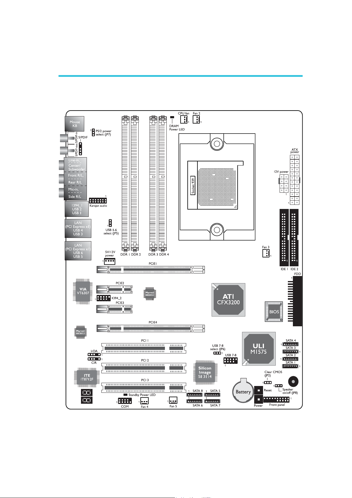
Chapter 2 - Hardware Installation
System Board Layout
2
25

2
.
.
.
.
.
.
.
.
Hardware Installation
Warning:
Electrostatic discharge (ESD) can damage your system board,
processor, disk drives, add-in boards, and other components. Perform
the upgrade instruction procedures described at an ESD workstation
only. If such a station is not available, you can provide some ESD
protection by wearing an antistatic wrist strap and attaching it to a
metal part of the system chassis. If a wrist strap is unavailable,
establish and maintain contact with the system chassis throughout
any procedures requiring ESD protection.
System Memory
.
.
.
.
Warning:
.
.
.
.
When the DRAM Power LED lit red, it indicates that power is
present on the DDR sockets. Power-off the PC then unplug the
power cord prior to installing any memory modules. Failure to do so
will cause severe damage to the motherboard and components.
DRAM
Power LED
Channel A
DDR 1
DDR 2
DDR 3
Channel B
DDR 4
The system board supports DDR SDRAM DIMM. Double Data
Rate SDRAM (DDR SDRAM) is a type of SDRAM that doubles the
data rate through reading and writing at both the rising and falling
edge of each clock. This effectively doubles the speed of operation
therefore doubling the speed of data transfer. Refer to chapter 1
(System Memory section) for detailed specification of the memory
supported by the system board.
26

Hardware Installation
The four DDR DIMM sockets on the system board are divided into 2
channels:
Channel A - DDR 1 and DDR 2
Channel B - DDR 3 and DDR 4
The system board supports the following memory interface.
Single Channel (SC)
Data will be accessed in chunks of 64 bits (8B) from the memory
channels.
Dual Channel (DC)
Data will be accessed in chunks of 128 bits from the memory
channels. Dual channel provides better system performance because
it doubles the data transfer rate.
2
Single Channel
Dual Channel
BIOS Setting
Configure the system memory in the Genie BIOS Setting submenu
(“DRAM Configuration” section) of the BIOS.
• DIMMs are on the same channel.
• DIMMs in a channel can be identical or
completely different. However, we highly recommend using identical DIMMs.
• Not all slots need to be populated.
• DIMMs of the same memory configura-
tion are on different channels.
27

2
Hardware Installation
The integrated memory controller in AMD's 64-bit Socket 939
series CPU will directly catch data transmission from DDR RAM
without passing through the North bridge. Therefore when using 4
identical double side DIMMs or using 2 DIMMs in non-dual channels,
the memory speed will reduce to DDR333. Please refer to the
detailed memory speed shown below.
Memory Speed
DDR400
DDR400
DDR400
DDR400
DDR400
DDR400
DDR400
DDR333
DDR400
DDR333
"S": Single side DIMM
"D": Double side DIMM
DIMM 1
S
D
S
D
S
D
S
D
DIMM 2
S
D
S
D
DIMM 3
S
D
S
D
S
D
DIMM 4
S
D
A DIMM's SPD is originally fixed at 1T. When modules are inserted
in DIMM 1 and DIMM 3, the SPD must be 2T for better system
stability. We recommend inserting DIMMs in DIMM 2 and DIMM 4.
28
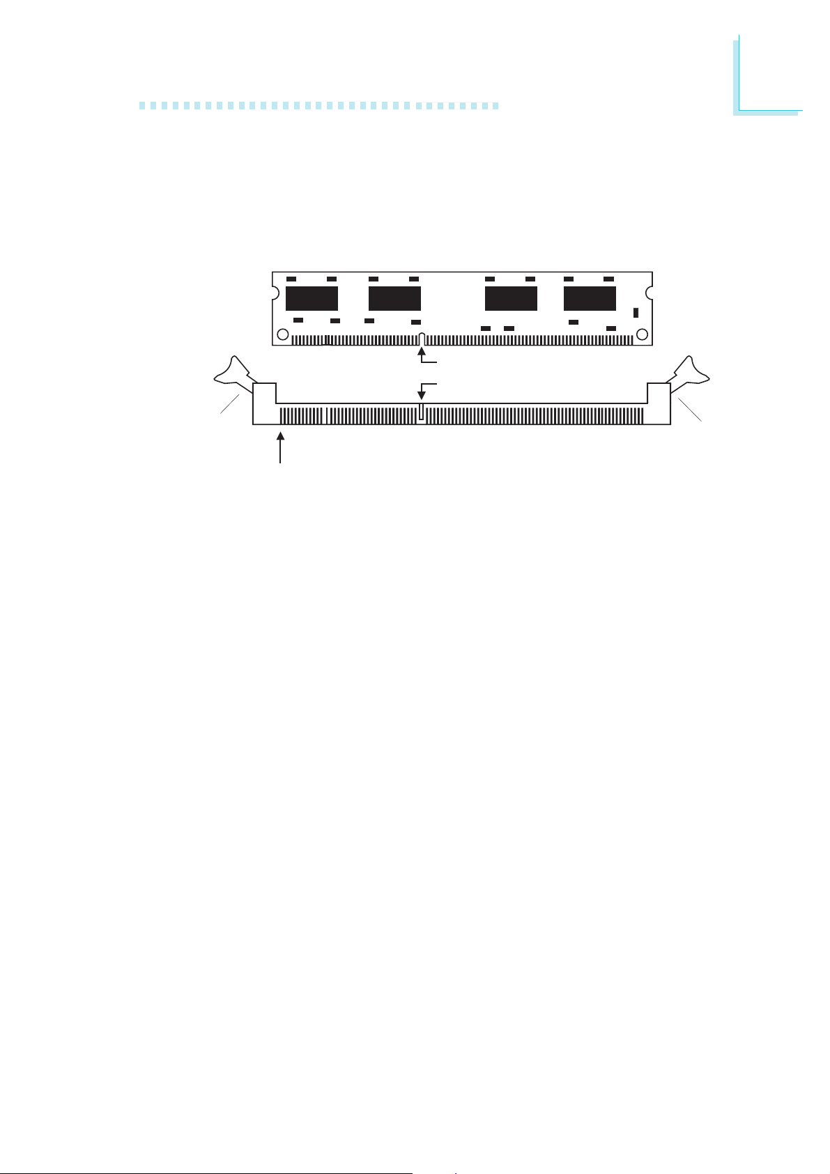
Installing the DIM Module
A DIM module simply snaps into a DIMM socket on the system
board. Pin 1 of the DIM module must correspond with Pin 1 of the
socket.
Hardware Installation
2
Notch
Key
Tab
Pin 1
1. Pull the “tabs” which are at the ends of the socket to the side.
2. Position the DIMM above the socket with the “notch” in the
module aligned with the “key” on the socket.
3. Seat the module vertically into the socket. Make sure it is
completely seated. The tabs will hold the DIMM in place.
Tab
29
2
Hardware Installation
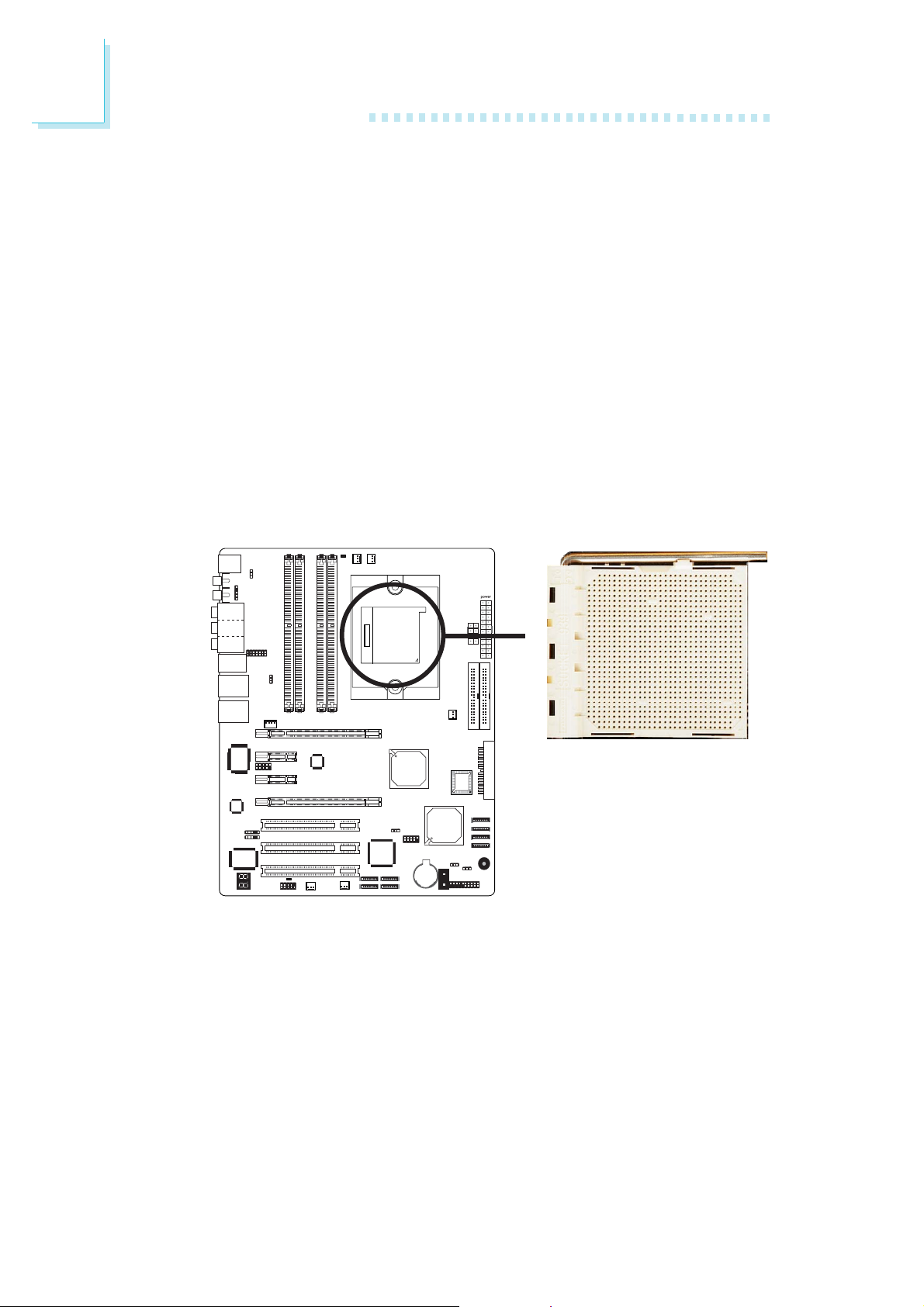
CPU
Overview
The system board is equipped with a surface mount 939-pin CPU
socket. This socket is exclusively designed for installing an AMD CPU.
Installing the CPU
1. Make sure the PC and all other peripheral devices connected to
it has been powered down.
2. Disconnect all power cords and cables.
3. Locate the 939-pin CPU socket on the system board.
X
30
 Loading...