

Page 1

935-DP45T1-600G
05800820E
System Board
User’s Manual
Page 2

Copyright
This publication contains information that is protected by copyright. No part of it
may be reproduced in any form or by any means or used to make any transformation/adaptation without the prior written permission from the copyright holders.
This publication is provided for informational purposes only. The manufacturer
makes no representations or warranties with respect to the contents or use of
this manual and specifically disclaims any express or implied warranties of
merchantability or fitness for any particular purpose. The user will assume the
entire risk of the use or the results of the use of this document. Further, the
manufacturer reserves the right to revise this publication and make changes to its
contents at any time, without obligation to notify any person or entity of such
revisions or changes.
© 2008. All Rights Reserved.
Trademarks
Windows® 2000 and Windows® XP are registered trademarks of Microsoft
Corporation. Award is a registered trademark of Award Software, Inc. Other
trademarks and registered trademarks of products appearing in this manual are
the properties of their respective holders.
FCC and DOC Statement on Class B
This equipment has been tested and found to comply with the limits for a Class
B digital device, pursuant to Part 15 of the FCC rules. These limits are designed
to provide reasonable protection against harmful interference when the equipment is operated in a residential installation. This equipment generates, uses and
can radiate radio frequency energy and, if not installed and used in accordance
with the instruction manual, may cause harmful interference to radio communications. However, there is no guarantee that interference will not occur in a particular installation. If this equipment does cause harmful interference to radio or
television reception, which can be determined by turning the equipment off and
on, the user is encouraged to try to correct the interference by one or more of
the following measures:
• Reorient or relocate the receiving antenna.
• Increase the separation between the equipment and the receiver.
• Connect the equipment into an outlet on a circuit different from that to
which the receiver is connected.
• Consult the dealer or an experienced radio TV technician for help.
Notice:
1. The changes or modifications not expressly approved by the party responsible for compliance could void the user's authority to operate the equipment.
2. Shielded interface cables must be used in order to comply with the emission
limits.
Page 3

Table of Contents
About this Manual................................................................................
Warranty.................................................................................................
Static Electricity Precaution................................................................
Safety Measures.....................................................................................
About the Package...............................................................................
Before Using the System Board.........................................................
System Board Layout............................................................................
English.....................................................................................................
Français...................................................................................................
Deutsch...................................................................................................
Español....................................................................................................
General Debug LED POST and Troubleshooting ........................
4
4
5
5
6
6
7
8
32
59
85
111
Page 4

Introduction
1
4
About this Manual
An electronic file of this manual is included in the CD. To view the
user’s manual in the CD, insert the CD into a CD-ROM drive. The
autorun screen (Main Board Utility CD) will appear. Click the
“TOOLS” icon then click “Manual” on the main menu.
For additional information on the system board, please download
the complete version of the manual from DFI’s website. Visit
www.dfi.com.
Warranty
1. Warranty does not cover damages or failures that arised from
misuse of the product, inability to use the product, unauthorized
replacement or alteration of components and product specifications.
2. The warranty is void if the product has been subjected to physical abuse, improper installation, modification, accidents or unauthorized repair of the product.
3. Unless otherwise instructed in this user’s manual, the user may
not, under any circumstances, attempt to perform service, adjustments or repairs on the product, whether in or out of warranty.
It must be returned to the purchase point, factory or authorized
service agency for all such work.
4. We will not be liable for any indirect, special, incidental or
consequencial damages to the product that has been modified
or altered.
Page 5
1
Introduction
5
Static Electricity Precautions
It is quite easy to inadvertently damage your PC, system board,
components or devices even before installing them in your system
unit. Static electrical discharge can damage computer components
without causing any signs of physical damage. You must take extra
care in handling them to ensure against electrostatic build-up.
1. To prevent electrostatic build-up, leave the system board in its
anti-static bag until you are ready to install it.
2. Wear an antistatic wrist strap.
3. Do all preparation work on a static-free surface.
4. Hold the device only by its edges. Be careful not to touch any of
the components, contacts or connections.
5. Avoid touching the pins or contacts on all modules and connectors. Hold modules or connectors by their ends.
Important:
Electrostatic discharge (ESD) can damage your processor, disk
drive and other components. Perform the upgrade instruction
procedures described at an ESD workstation only. If such a
station is not available, you can provide some ESD protection
by wearing an antistatic wrist strap and attaching it to a metal
part of the system chassis. If a wrist strap is unavailable, establish and maintain contact with the system chassis throughout
any procedures requiring ESD protection.
Safety Measures
To avoid damage to the system:
• Use the correct AC input voltage range
..
..
.
To reduce the risk of electric shock:
• Unplug the power cord before removing the system chassis
cover for installation or servicing. After installation or servicing,
cover the system chassis before plugging the power cord.
Battery:
• Danger of explosion if battery incorrectly replaced.
• Replace only with the same or equivalent type recommend
by
the manufacturer.
• Dispose of used batteries according to local ordinance.
Page 6

Introduction
1
6
About the Package
The system board package contains the following items. If any of
these items are missing or damaged, please contact your dealer or
sales representative for assistance.
; The system board
; A user’s manual
; One IDE cable
; One FDD cable
; Two Serial ATA data cables
; One power cable with 2 Serial ATA power connectors
; One RAID floppy diskette
; One I/O shield
; One “Mainboard Utility” CD
The system board and accessories in the package may not come
similar to the information listed above. This may differ in accordance
to the sales region or models in which it was sold. For more information about the standard package in your region, please contact
your dealer or sales representative.
Before Using the System Board
Before using the system board, prepare basic system components.
If you are installing the system board in a new system, you will need
at least the following internal components.
• A CPU
• Memor y module
• Storage devices such as hard disk drive, CD-ROM, etc.
You will also need external system peripherals you intend to use
which will normally include at least a keyboard, a mouse and a video
display monitor.
Page 7
1
Introduction
7
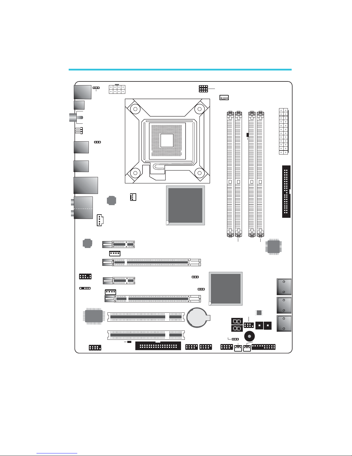
System Board Layout
Mouse
KB
Optical
S/PDIF-out
LAN
USB 7
USB 6
Line-in
Front R/L
Mic-in
Center/
Subwoofer
Side R/L
Rear R/L
1
1
Coaxial RCA
S/PDIF-out
USB 9
USB 8
USB 11
USB 10
CD-in
1
ITE
IT8718F
SATA 3
SATA 2
SATA 1
SATA 0
SATA 5
SATA 4
System fan
1
Front panel
1
1
Chassis fan
USB 4-5
USB 2-3
USB 0-1
FDD
1
1
COM
Battery
Front audio
1
1
IrDA
5V/12V
power
1
5V/12V
power
1
PCIE 1
PCIE 3
2412
ATX
power
1
13
JMicron
JMB368
1
1
CPU fan
DIMM 1
DIMM 2
DIMM 4
DIMM 3
12V power
1
JP17
JP18
1
1
JP19
1
SPI Flash
BIOS
ResetPower
1
Socket 775
1
PS/2 power
select (J 7)P
Marvell
88E8053
USB 6-11 power
select (J 5)P
1
NB Fan
IDE
USB 0-5 power
select (J )P6
1
1
Intel
ICH10R
Intel
P45
Standby
Power LED
PCI 1
PCI 2
PCIE 2
PCIE 4
Realtek
ALC885
DRAM Power LED
Clear CMOS (JP8)
CPU FSB select
(JP17-JP19)
11
1
Clear
CMOS (JP2)
Secondary RTC
reset (JP12)
1
2
7
8
Download
BIOS (JP13)Flash
Page 8
English
E
8
English
Chapter 1 - Introduction
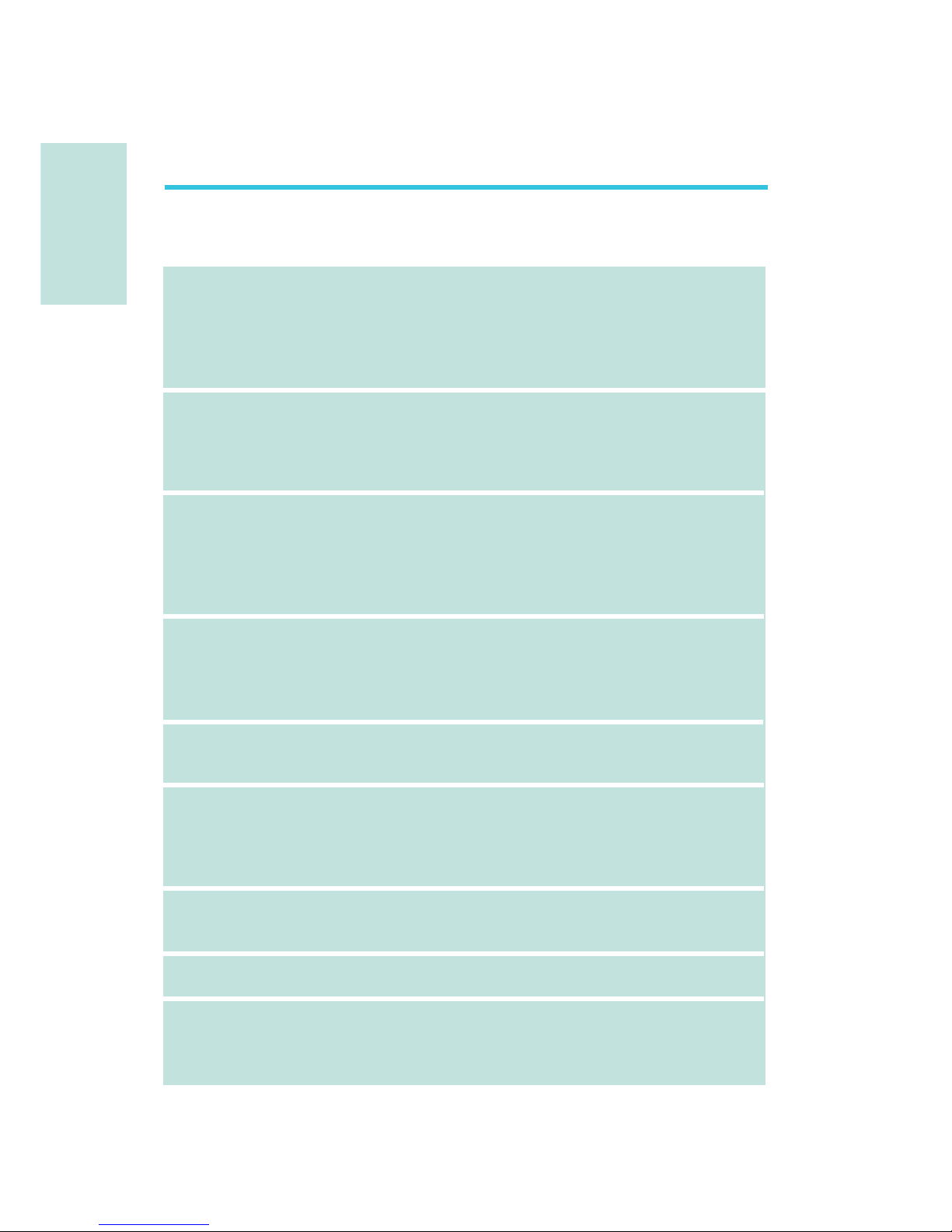
Specifications
Processor
Chipset
System Memory
Expansion Slots
BIOS
Audio
LAN
IDE
Serial ATA with
RAID
• LGA 775 socket for:
- Intel® CoreTM2 Quad and Intel® CoreTM2 Duo
• Supports Intel Enhanced Memory 64 Technology (EMT64T)
• Supports Enhanced Intel SpeedStep Technology (EIST)
• Supports Intel Hyper-Threading Technology
• Supports 1333/1066/800MHz FSB
• Intel
®
chipset
- Northbridge:
Intel® P45 Express chipset
Intel® Fast Memory Access technology
- Southbridge: Intel® ICH10R
• Four 240-pin DDR2 DIMM sockets
• Supports DDR2 667/800 MHz
• Delivers up to 12.8Gb/s bandwidth
• Supports dual channel (128-bit wide) memory interface
• Supports up to 8GB system memory
• Supports unbuffered x8 and x16 DIMMs
• 2 PCI Express (Gen 2) x16 slots
- 2-way CrossFire: One slot operating at x16 (16-lane port)
or two slots each operating at x8 (8-lane ports) bandwidth
• 2 PCI Express x1 slots
• 2 PCI slots
• Award BIOS
• 8Mbit SPI flash BIOS
• CMOS Reloaded
• Realtek ALC885 High Definition audio CODEC
• 8-channel audio output
• DAC SNR/ADC SNR of 106dB/101dB
• Full-rate lossless content protection technology
• Optical S/PDIF-out and coaxial RCA S/PDIF-out interfaces
• Marvell 88E8053 PCIE Gigabit LAN controller
• Fully compliant to IEEE 802.3 (10BASE-T), 802.3u (100BASETX) and 802.3ab (1000BASE-T) standards
• JMicron JMB368 PCI Express to PATA host controller
• Supports up to 2 UltraDMA 33/66/100Mbps IDE devices
• Intel Matrix Storage technology
• Supports up to 6 SATA devices
• SATA speed up to 3Gb/s
• RAID 0, RAID 1, RAID 0+1 and RAID 5
Page 9

E
English
9
English
Rear Panel I/O
Internal I/O
Power Management
Hardware Monitor
PCB
• 1 mini-DIN-6 PS/2 mouse port
• 1 mini-DIN-6 PS/2 keyboard port
• 1 optical S/PDIF-out port
• 1 coaxial RCA S/PDIF-out port
• 6 USB 2.0/1.1 ports
• 1 RJ45 LAN port
• Center/subwoofer, rear R/L and side R/L jacks
• Line-in, line-out (front R/L) and mic-in jacks
• 3 connectors for 6 additional external USB 2.0 ports
• 1 connector for an external COM port
• 1 front audio connector
• 1 CD-in connector
• 1 IrDA connector
• 6 Serial ATA connectors
• 1 40-pin IDE connector
• 1 floppy connector
• 1 24-pin ATX power connector
• 1 8-pin 12V power connector
• 2 4-pin 5V/12V power connectors (FDD type)
• 1 front panel connector
• 4 fan connectors
• 1 download flash BIOS connector
• 1 diagnostic LED
• EZ touch switches (power switch and reset switch)
• ACPI and OS Directed Power Management
• ACPI STR (Suspend to RAM) function
• Wake-On-PS/2 Keyboard/Mouse
• Wake-On-USB Keyboard/Mouse
• Wake-On-LAN
• Wake-On-Ring
• RTC timer to power-on the system
• AC power failure recovery
• Monitors CPU/system/Northbridge temperature and overheat alarm
• Monitors Vcore/Vdimm/Vnb/VCC5/12V/V5sb/Vbat voltages
• Monitors the speed of the cooling fans
• CPU Overheat Protection function monitors CPU temperature
and fan during system boot-up - automatic shutdown upon system overheat
• 4 layers, ATX form factor
• 24.5cm (9.64") x 30.5cm (12")
Page 10
English
E
10
English
Chapter 2 - Hardware Installation
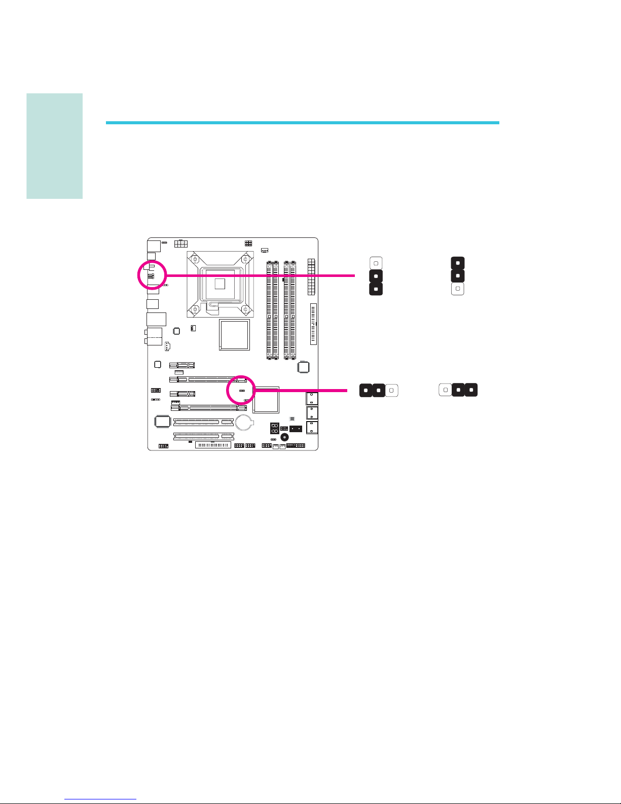
Jumper Settings
If you encounter the following,
a) CMOS data becomes corrupted.
b) You forgot the supervisor or user password.
c) The overclocked settings in the BIOS resulted to the system’s in-
stability or caused system boot up problems.
you can reconfigure the system with the default values stored in the
ROM BIOS.
JP8 is accessible from the rear panel of the system. This provides
convenience by allowing you to clear the CMOS without having to
remove the chassis cover.
Clear CMOS Data
Clearing CMOS Data using Jumpers
2-3 On:
Clear CMOS Data
1-2 On: Normal
(default)
JP2
JP8
X
2-3 On:
Clear CMOS Data
1-2 On: Normal
(default)
1
3
2
1
3
2
X
3
1
23
1
2
Page 11

E
English
11
English
To load the default values stored in the ROM BIOS, please follow
the steps below.
1. Power-off the system then unplug the power cord.
2. Set JP2 or JP8 pins 2 and 3 to On. Wait for a few seconds and
set JP2 or JP8 back to its default setting, pins 1 and 2 On.
3. Now plug the power cord then power-on the system.
Page 12
English
E
12
English
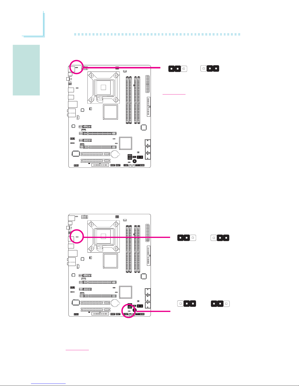
PS/2 Power Select
Selecting 5VSB will allow you to use the PS/2 keyboard or PS/2
mouse to wake up the system.
X
JP7
2-3 On:
5VSB
1-2 On: 5V
(default)
USB Power Select
X
USB 6-11
(JP5)
X
USB 0-5
(JP6)
2-3 On: 5VSB1-2 On: 5V
(default)
2-3 On: 5VSB1-2 On: 5V
(default)
Selecting 5VSB will allow you to use the USB keyboard or USB
mouse to wake up the system.
Important:
The 5VSB power source of your power supply must support ≥1.5A (2 devices)
or ≥2A (3 or more devices).
Important:
The 5VSB power source of your
power supply must support
≥720mA.
312312
312 312
31
2
312
Page 13
E
English
13
English
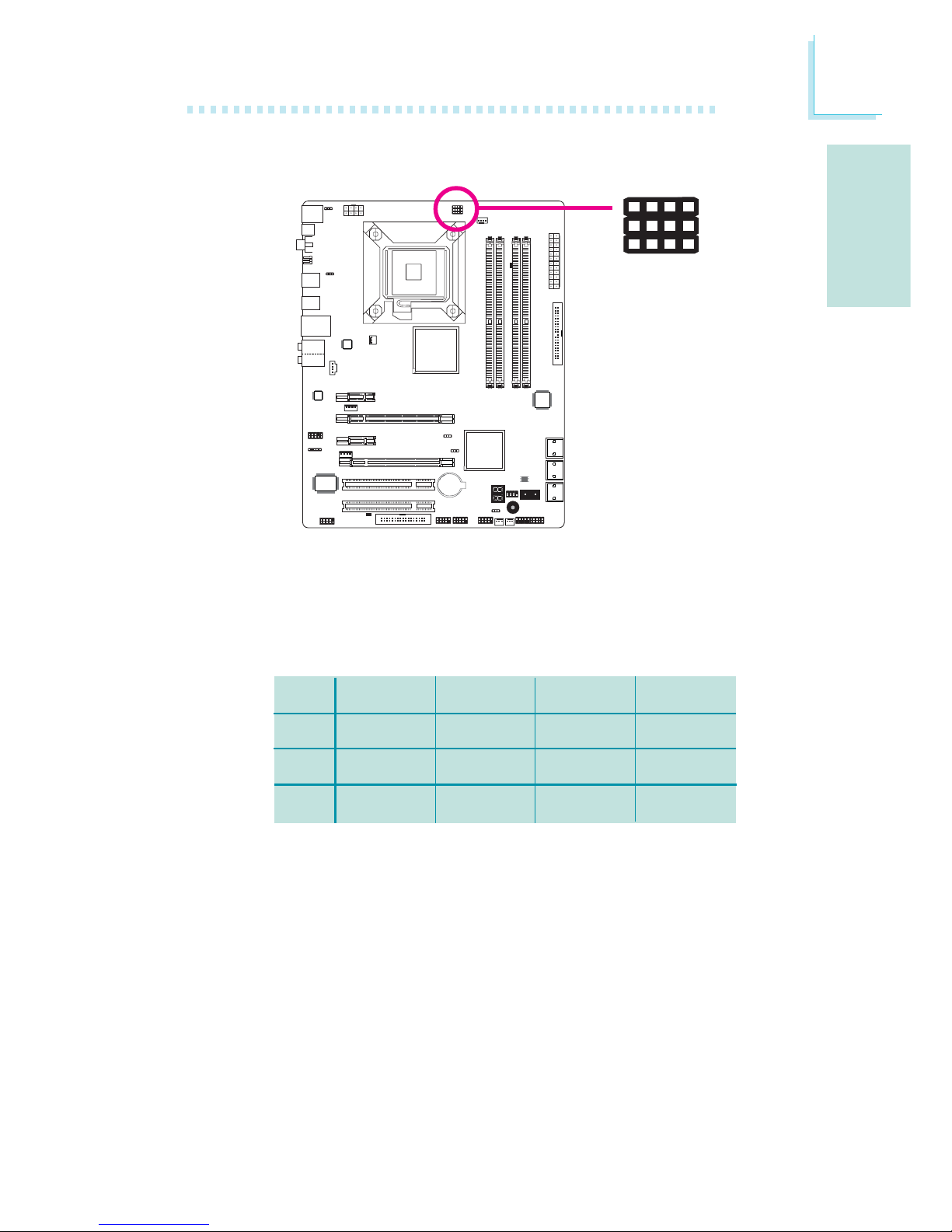
By default, the three jumpers are all set to pins 1 and 2 On. This
setting will allow the system to automatically run according to the
CPU’s FSB. If you want to change the settings, please refer to the
table below.
JP17
JP18
JP19
By CPU
1-2 On
1-2 On
1-2 On
FSB 800
2-3 On
3-4 On
2-3 On
FSB 1066
2-3 On
2-3 On
2-3 On
FSB 1333
2-3 On
2-3 On
3-4 On
CPU FSB Select
X
JP17
423
JP18
JP19
1
Page 14
English
E
14
English
Rear Panel I/O Ports
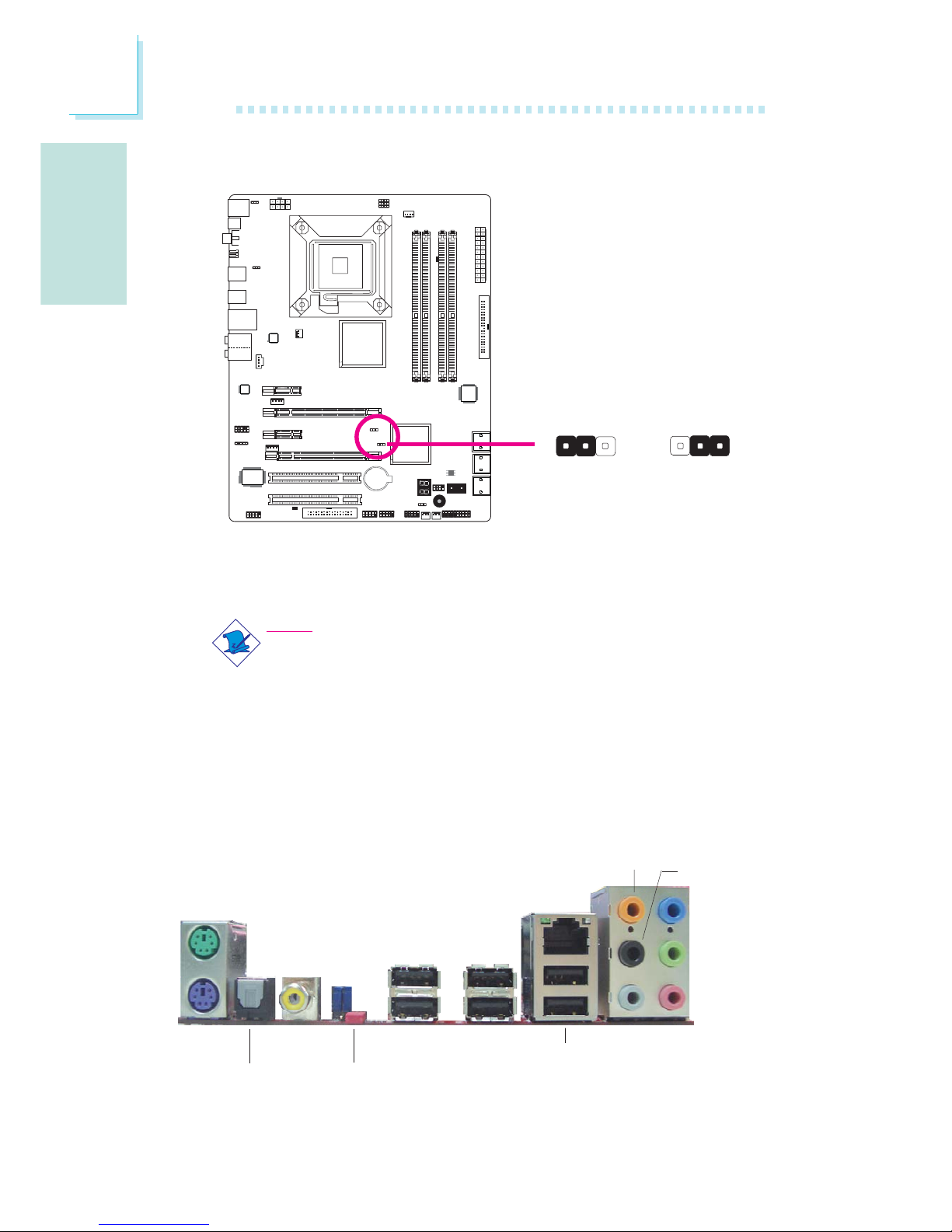
Secondary RTC Reset
When the RTC battery is removed, this jumper resets the
manageability register bits in the RTC.
Note:
1. The SRTCRST# input must always be high when all other
RTC power planes are on.
2. In the case where the RTC battery is dead or missing on
the platform, the SRTCRST# pin must rise before the
RSMRST# pin.
PS/2 K/B
Optical
S/PDIF-out
USB 10-11
USB 6-7
Coaxial
S/PDIF-out
Mic-in
Side R/L
Center/
Subwoofer
Rear R/L
Line-in
Front R/L
LAN
PS/2
Mouse
USB 8-9
Clear
CMOS
jumper
2-3 On:
RTC reset
1-2 On: Normal
(default)
X
JP12
132 132
Page 15
E
English
15
English
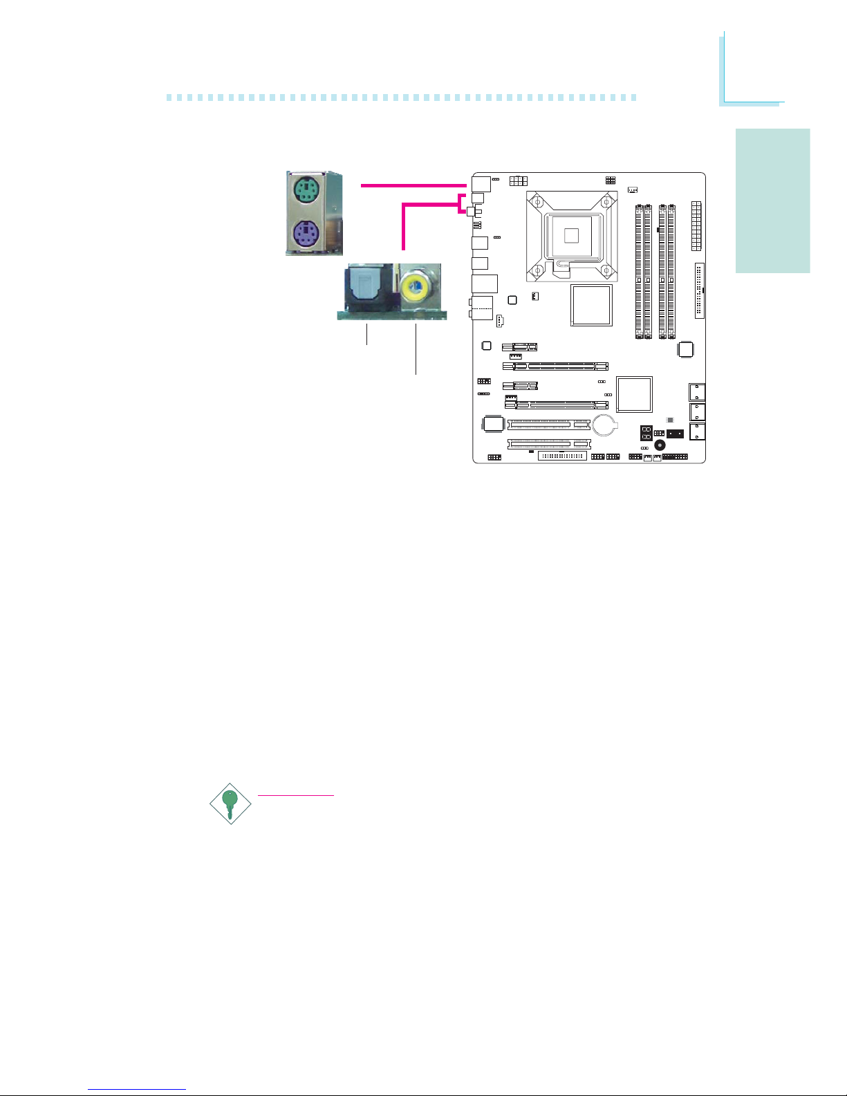
PS/2 Mouse and PS/2 Keyboard Ports
These ports are used to connect a PS/2 mouse and a PS/2 keyboard.
Optical S/PDIF
The optical S/PDIF jack is used to connect an external audio output
device using an optical S/PDIF cable.
Coaxial RCA S/PDIF
The coaxial RCA S/PDIF jack is used to connect an external audio
output device using a coaxial S/PDIF cable.
Important:
DO NOT use optical S/PDIF and Coaxial RCA S/PDIF at the
same time.
PS/2 Ports and S/PDIF Ports
W
PS/2 Mouse
PS/2 KB
Optical
S/PDIF
Coaxial RCA
S/PDIF
W
Page 16
English
E
16
English
1
VCC
-Data
+Data
GND
Key
VCC
-Data
+Data
GND
N. C.
2
10
9
W
USB 4-5
W
USB 0-1
USB 9
W
LAN
USB 8
USB 11
USB 10
USB 7
USB 6
USB Ports and LAN Port
USB Ports
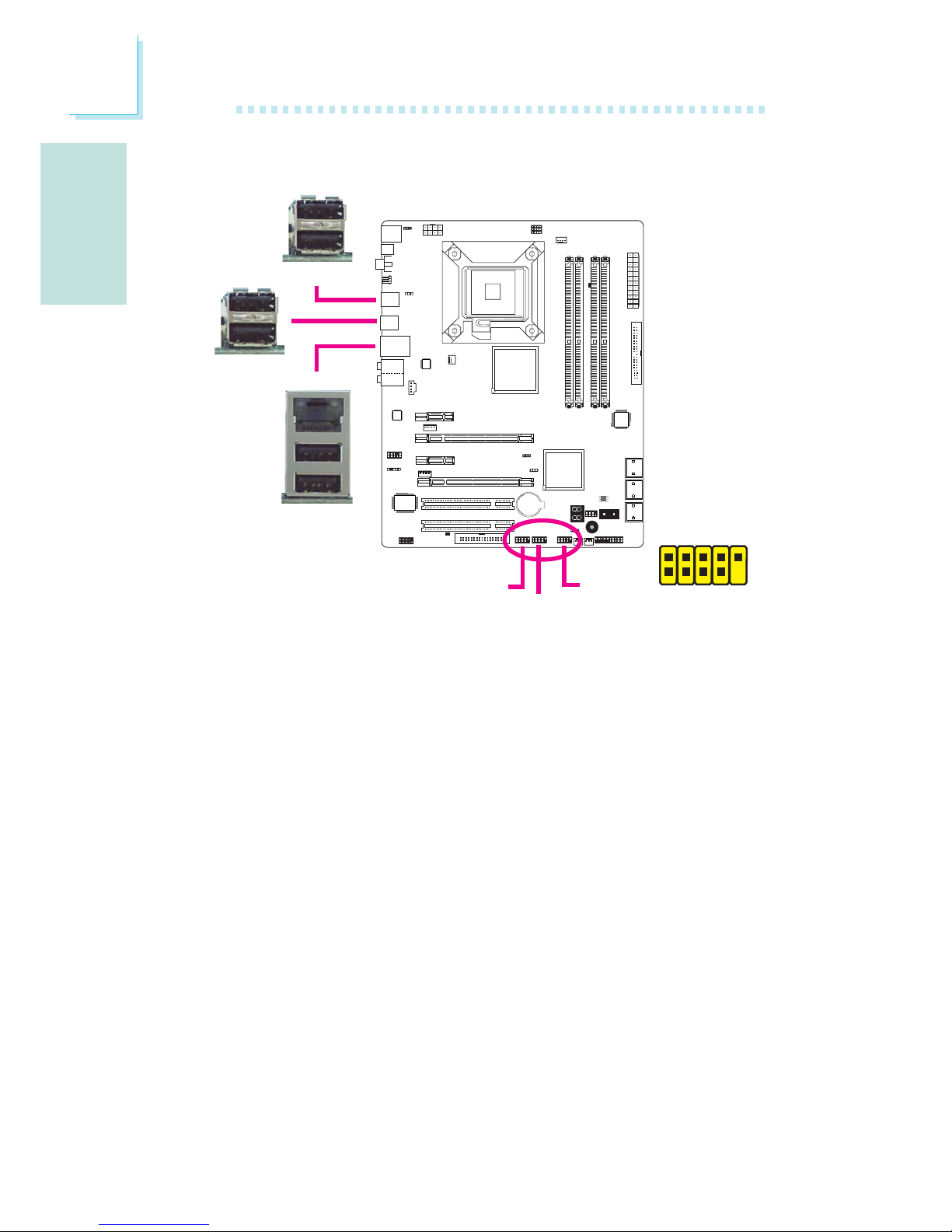
The USB ports are used to connect USB 2.0/1.1 devices. The 10-pin
connectors allow you to connect 6 additional USB 2.0/1.1 ports.
Your USB ports may come mounted on a card-edge bracket. Install
the card-edge bracket to an available slot at the rear of the system
chassis then connect the USB port cables to these connectors.
LAN Port
The LAN port allows the system board to connect to a local area
network by means of a network hub.
USB 2-3
Page 17
E
English
17
English
Rear Panel Audio
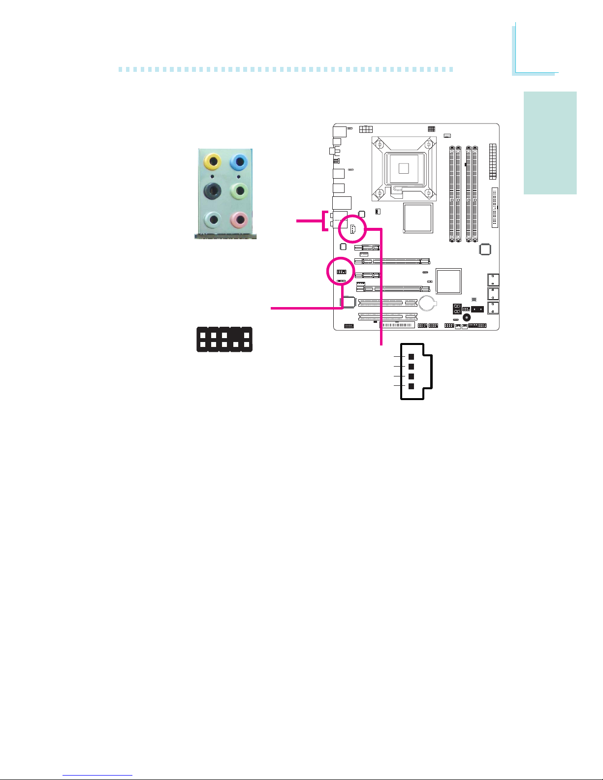
Center/Subwoofer Jack (Orange)
This jack is used to connect to the center and subwoofer speakers of the audio system.
Rear Right/Left Jack (Black)
This jack is used to connect to the rear right and rear left speakers of the audio system.
Side Right/Left Jack (Gray)
This jack is used to connect to the side left and side right speakers of the audio system.
Line-in (Light Blue)
This jack is used to connect any audio devices such as Hi-fi set,
CD player, tape player, AM/FM radio tuner, synthesizer, etc.
Line-out - Front Right/Left Jack (Lime)
This jack is used to connect to the front right and front left
speakers of the audio system.
Audio and CD-In
W
W
Rear audio
Front audio
Front R/L
Line-in
Mic-in
Rear R/L
Center/
Subwoofer
Side R/L
1
2
10
Mic-L
Mic-R
Line-out-R
Front-sense
Line-out-L
GND
Presense-signal
Mic-jack-sense
Key
Line-out-jack-sense
9
4
1
Left audio channel
Right audio channel
Ground
Ground
W
CD-in
Page 18
English
E
18
English
Serial ATA Connectors
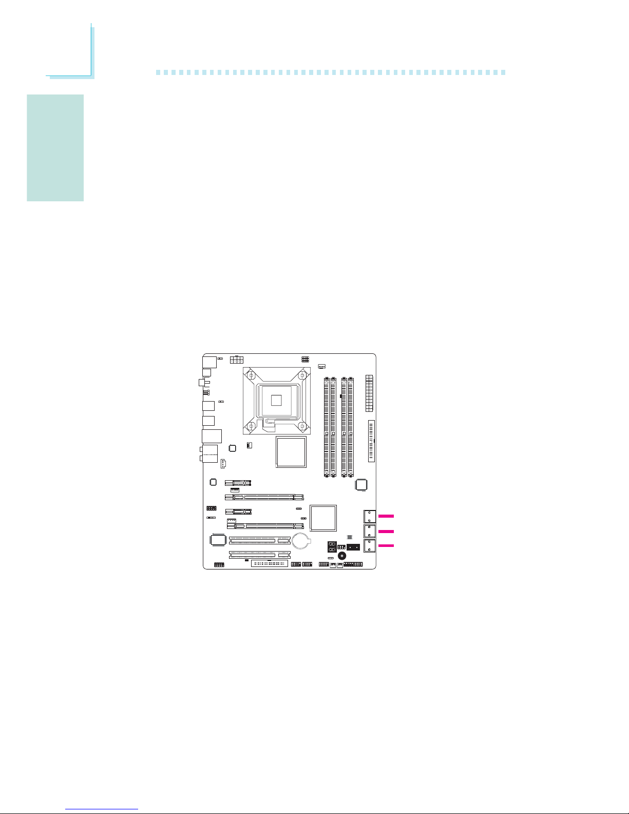
The Serial ATA (SATA) connectors are used to connect Serial ATA
drives. Connect one end of the Serial ATA cable to a Serial ATA
connector and the other end to your Serial ATA device.
Configuring RAID
Refer to the RAID chapter in this manual for more information
about creating RAID on Serial ATA drives.
SATA 2-3
SATA 0-1
SATA 4-5
Mic-in Jack (Pink)
This jack is used to connect an external microphone.
Front Audio
The front audio connector is used to connect to the line-out and
mic-in jacks that are at the front panel of your system.
CD-in
The CD-in connector is used to receive audio from a CD-ROM
drive, TV tuner or MPEG card.
Internal I/O Connectors
Page 19
E
English
19
English
X
40
39
21
FDD Connector and IDE Connector
FDD Connector
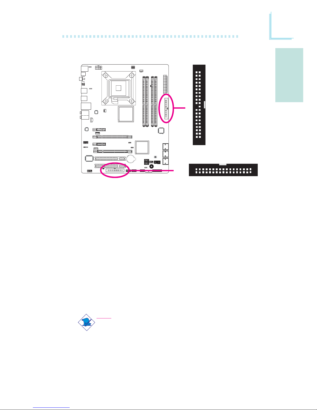
The floppy disk drive connector is used to connect a floppy drive.
Insert one end of the floppy cable into this connector and the other
end-most connector to the floppy drive. The colored edge of the
cable should align with pin 1 of this connector.
IDE Connector
The IDE disk drive connector is used to connect 2 IDE disk drives.
An IDE cable have 3 connectors on them, one that plugs into this
connector and the other 2 connects to IDE devices. The connector
at the end of the cable is for the Master drive and the connector in
the middle of the cable is for the Slave drive. The colored edge of
the cable should align with pin 1 of this connector.
Note:
When using two IDE drives, one must be set as the master
and the other as the slave. Follow the instructions provided by
the drive manufacturer for setting the jumpers and/or switches
on the drives.
X
IDE
FDD
34
33
1
2
Page 20
English
E
20
English
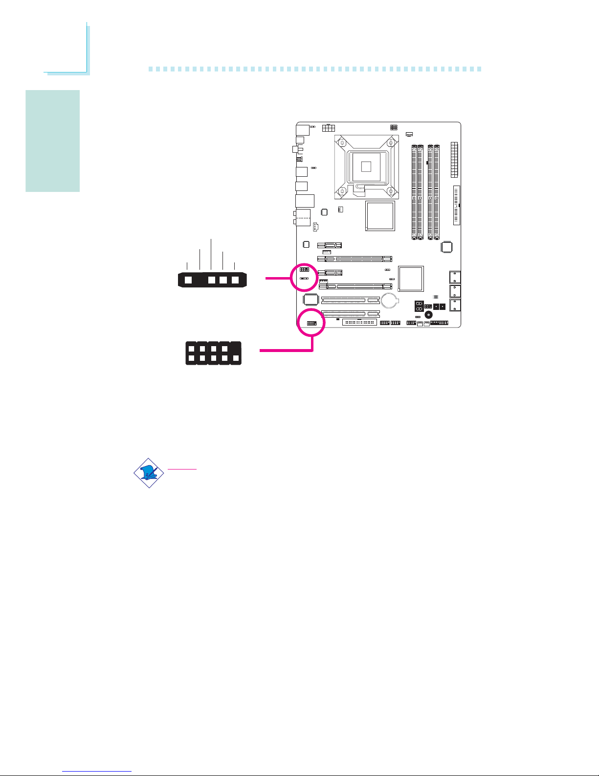
IrDA and Serial (COM) Connectors
IrDA Connector
This connector is used to connect an IrDA module.
Note:
The sequence of the pin functions on some IrDA cable may be
reversed from the pin function defined on the system board.
Make sure to connect the cable connector to the IrDA
connector according to their pin functions.
You may need to install the proper drivers in your operating system
to use the IrDA function. Refer to your operating system’s manual or
documentation for more information.
Serial (COM) Connector
The serial (COM) connector is used to connect modems, serial printers, remote display terminals, or other serial devices. Your COM port
may come mounted on a card-edge bracket. Install the card-edge
bracket to an available slot at the rear of the system chassis then
connect the serial port cable to this connector. The colored edge of
the cable should align with pin 1 of this connector.
W
1
9
2
CD
TD
RD
DTR
GND
RTS
DSR
CTS
RI
COM
15
VCC
N. C.
IRRX
Ground
IRTX
IrDA
X
Page 21
E
English
21
English
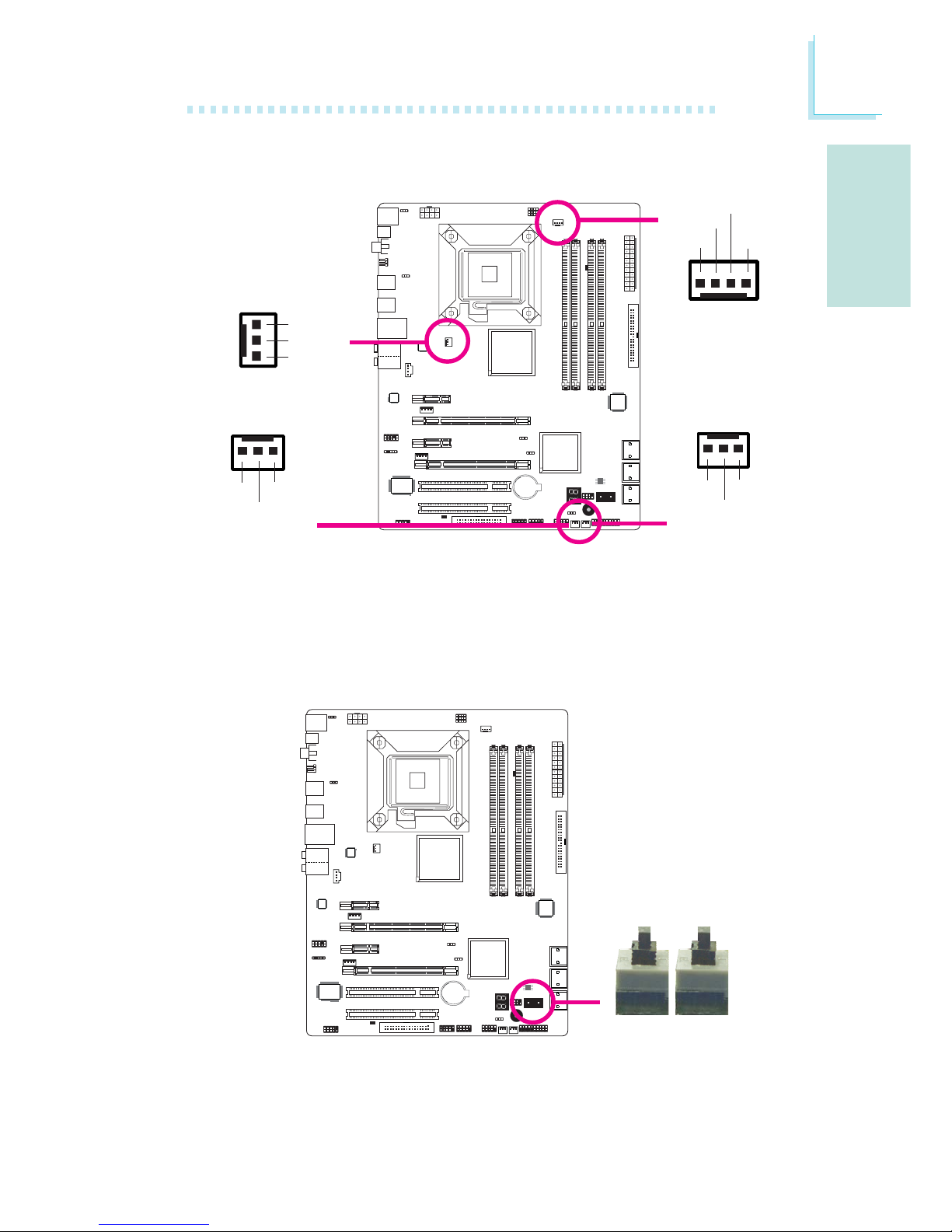
Cooling Fan Connectors
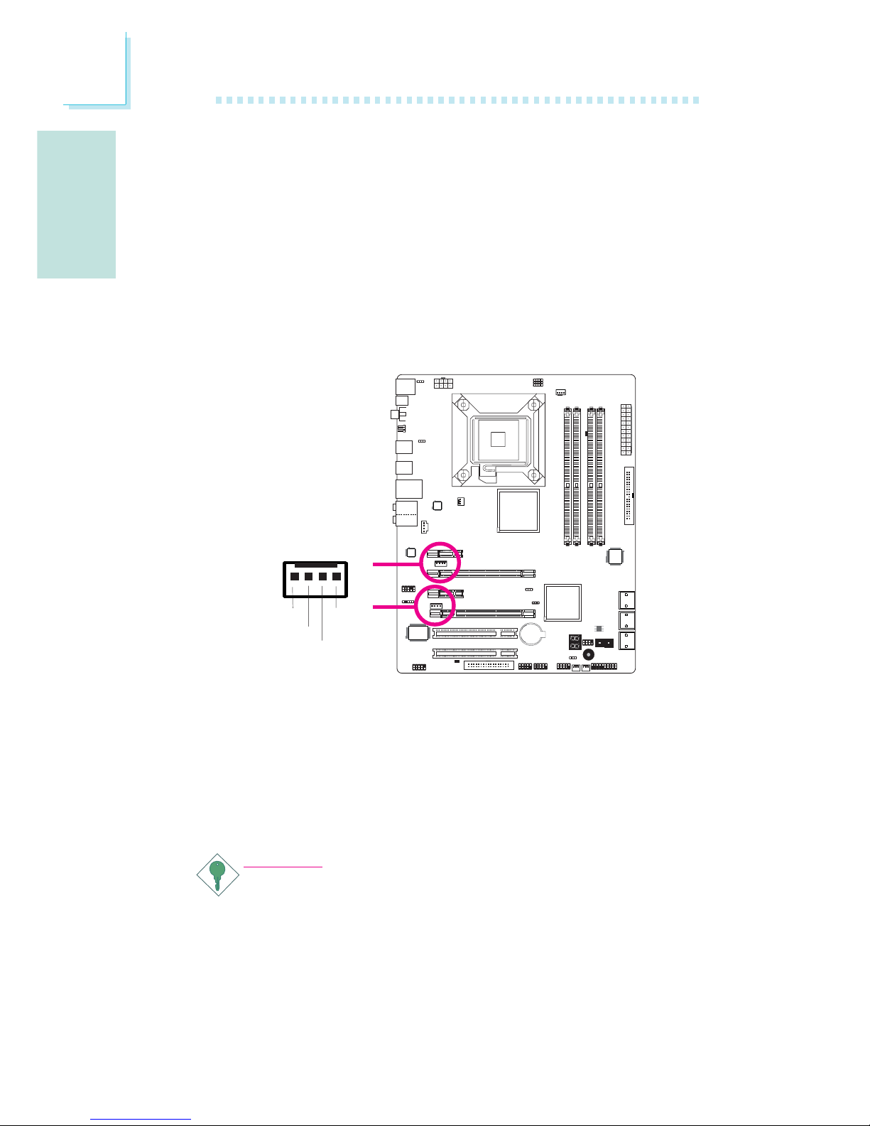
These fan connectors are used to connect cooling fans. Cooling fans
will provide adequate airflow throughout the chassis to prevent overheating the CPU and system board components.
EZ Touch Switches
The presence of the power switch and reset switch on the system
board are user-friendly especially to DIY users. They provide convenience in powering on and/or resetting the system while fine tuning
the system board before it is installed into the system chassis.
X
ResetPower
X
X
CPU fan
Chassis fan
System fan
X
NB fan
1
3
Sense
Power
On/Off
4
1
Sense
Power
Ground
Speed
Control
3
1
Ground
Power
Sense
X
3
1
Ground
Power
Sense
Page 22
English
E
22
English
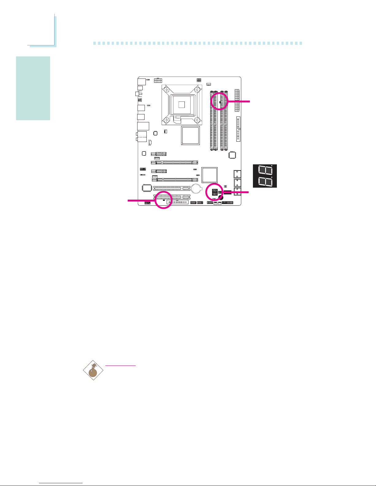
DRAM
Power LED
Standby
Power LED
LEDs
DRAM Power LED
This LED will light when the system’s power is on.
Standby Power LED
This LED will light when the system is in the standby mode.
Diagnostic LED
The Diagnostic LED displays POST codes. POST (Power-On Self
Tests) which is controlled by the BIOS is performed whenever you
power-on the system. POST will detect the status of the system and
its components. Each code displayed on the LED corresponds to a
certain system status.
Warning:
When the DRAM Power LED and/or Standby Power LED lit red,
it indicates that power is present on the DIMM sockets and/or
PCI slots. Power-off the PC then unplug the power cord prior to
installing any memory modules or add-in cards. Failure to do so
will cause severe damage to the motherboard and components.
.
.
.
.
.
.
.
.
Diagnostic
LED
Page 23
E
English
23
English
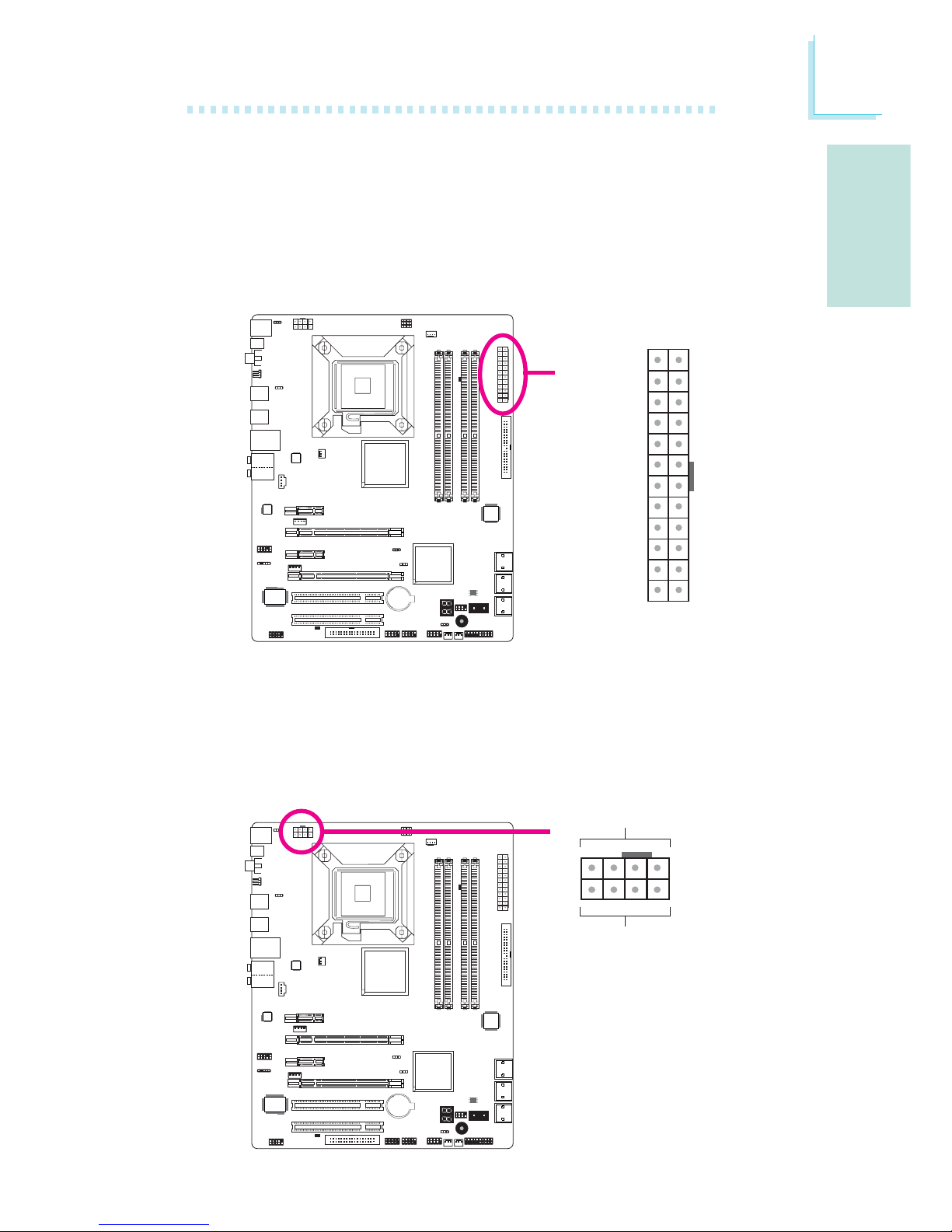
Power Connectors
Use a power supply that complies with the ATX12V Power Supply
Design Guide Version 1.1. An ATX12V power supply unit has a
standard 24-pin ATX main power connector that must be inserted
into this connector.
Your power supply unit may come with an 8-pin or 4-pin +12V
power connector. The +12V power enables the delivery of more
+12VDC current to the processor’s Voltage Regulator Module
(VRM). If available, it is preferable to use the 8-pin power; otherwise
connect a 4-pin power to this connector.
X
X
131
12 24
+3.3VDC
+3.3VDC
COM
+5VDC
COM
+5VDC
COM
PWR_OK
+5VSB
+12VDC
+12VDC
+3.3VDC
+3.3VDC
-12VDC
COM
PS_ON#
COM
COM
COM
NC
+5VDC
+5VDC
+5VDC
COM
+12V
Ground
14
58
Page 24
English
E
24
English
The FDD-type power connectors are additional power connectors. If
you are using more than one graphics cards, we recommend that
you plug a power cable from your power supply unit to the 5V/12V
power connector. This will provide more stability to the entire system.
The system board will still work even if the additional power connector is not connected.
The system board requires a minimum of 300 Watt power supply
to operate. Your system configuration (CPU power, amount of
memory, add-in cards, peripherals, etc.) may exceed the minimum
power requirement. To ensure that adequate power is provided, we
strongly recommend that you use a minimum of 400 Watt (or
greater) power supply.
Important:
Insufficient power supplied to the system may result in instability or the add-in boards and peripherals not functioning properly. Calculating the system’s approximate power usage is important to ensure that the power supply meets the system’s
consumption requirements.
The power connectors from the power supply unit are designed to
fit the 24-pin and 8-pin connectors in only one orientation. Make
sure to find the proper orientation before plugging the connectors.
1
4
+5V
+12V
Ground
Ground
Page 25

E
English
25
English
Restarting the PC
Normally, you can power-off the PC by:
1. Pressing the power button at the front panel of the chassis.
or
2. Pressing the power switch that is on the system board (note: not
all system boards come with this switch).
If for some reasons you need to totally cut off the power supplied
to the PC, switch off the power supply or unplug the power cord.
Take note though that if you intend to restart it at once, please
strictly follow the steps below.
1. The time where power is totally discharged varies among power
supplies. It's discharge time is highly dependent on the system's
configuration such as the wattage of the power supply, the sequence of the supplied power as well as the number of peripheral devices connected to the system. Due to this reason, we
strongly recommend that you wait for the Standby Power LED
(refer to the “LEDs” section in this chapter for the location of the
Standby Power LED) to lit off.
2. After the Standby Power LED has lit off, wait for 6 seconds
before powering on the PC.
If the system board is already enclosed in a chassis which apparently will not make the Standby Power LED visible, wait for 15
seconds before you restore power connections. 15 seconds is
approximately the time that will take the LED to lit off and the
time needed before restoring power.
The above will ensure protection and prevent damage to the
motherboard and components.
Page 26
English
E
26
English
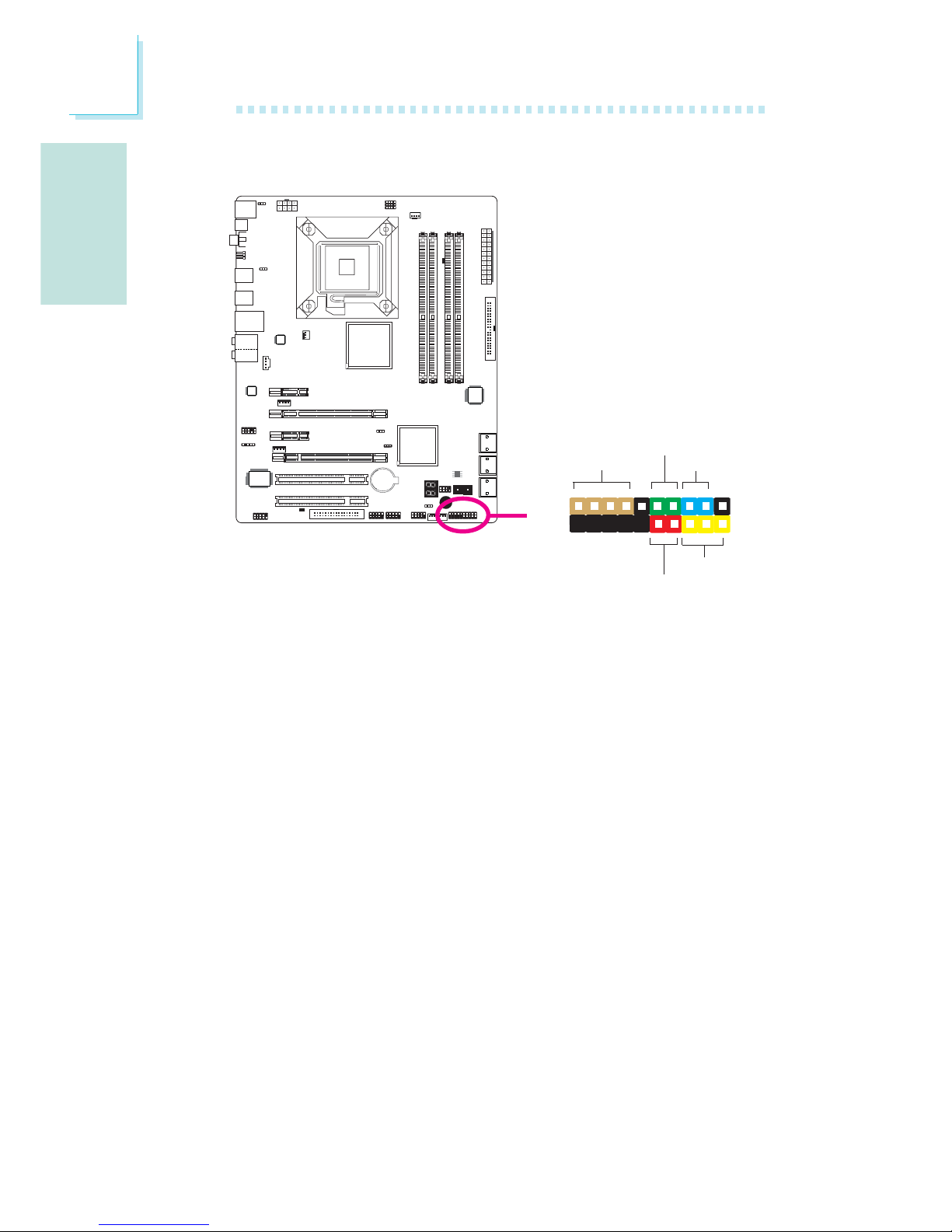
Front Panel Connectors
HD-LED: Primary/Secondary IDE LED
This LED will light when the hard drive is being accessed.
RESET: Reset Switch
This switch allows you to reboot without having to power off the
system thus prolonging the life of the power supply or system.
SPEAKER: Speaker Connector
This connects to the speaker installed in the system chassis.
ATX-SW: ATX Power Switch
Depending on the setting in the BIOS setup, this switch is a “dual
function power button” that will allow your system to enter the SoftOff or Suspend mode.
X
1
2
19
20
HD-LED
RESET
SPEAKER
PWR-LED
ATX-SW
Page 27
E
English
27
English
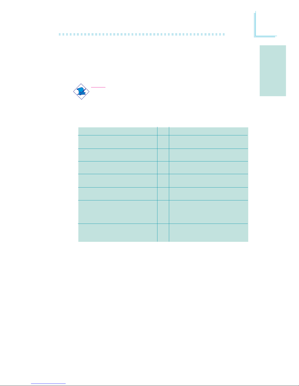
PWR-LED: Power/Standby LED
When the system’s power is on, this LED will light. When the system
is in the S1 (POS - Power On Suspend) or S3 (STR - Suspend To
RAM) state, it will blink every second.
Note:
If a system did not boot-up and the Power/Standby LED did
not light after it was powered-on, it may indicate that the CPU
or memory module was not installed properly. Please make
sure they are properly inserted into their corresponding socket.
Pin
3
5
14
16
8
10
18
20
7
9
13
15
17
19
2
4
6
HD-LED
(Primary/Secondary IDE LED)
Reserved
ATX-SW
(ATX power switch)
Reserved
RESET
(Reset switch)
SPEAKER
(Speaker connector)
PWR-LED
(Power/Standby LED)
Pin Assignment
HDD LED Power
HDD
N. C.
N. C.
PWRBT+
PWRBT-
N. C.
N. C.
Ground
H/W Reset
Speaker Data
N. C.
Ground
Speaker Power
LED Power (+)
LED Power (+)
LED Power (-) or Standby Signal
Page 28
English
E
28
English
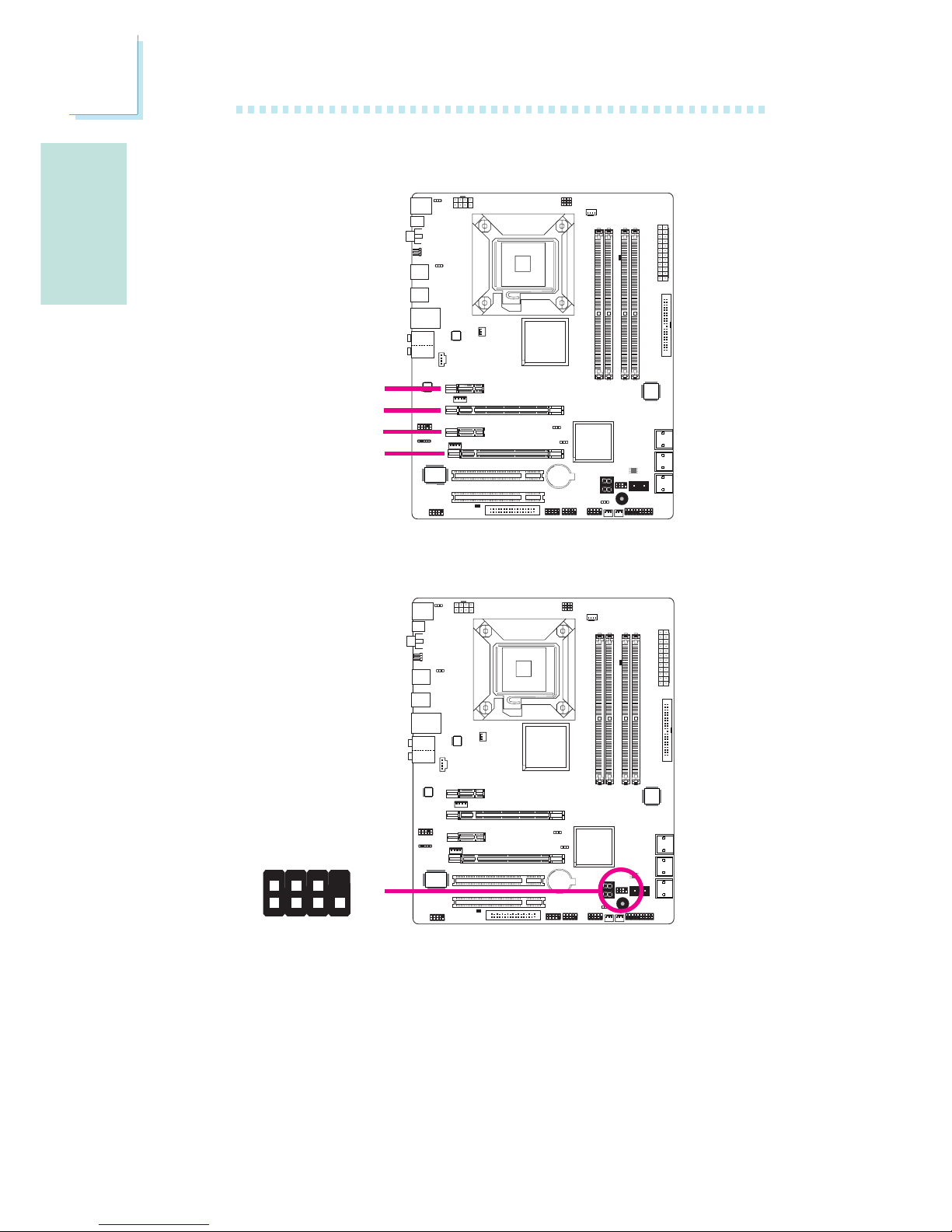
PCI Express Slots
PCI Express x1
PCI Express x16
PCI Express x16
Download Flash BIOS Connector
W
1
GROUND
2
8
7
SPI_VCC3
SPI_CS0B
SPI_MIS0
SPI_HOLD#
SPI_CLK
SPI_MOSI
PCI Express x1
Page 29

E
English
29
English
The Intel ICH10R chip alows configuring RAID on Serial ATA drives.
It supports RAID 0, RAID 1, RAID 0+1 and RAID 5.
RAID Levels
RAID 0 (Striped Disk Array without Fault Tolerance)
RAID 0 uses two new identical hard disk drives to read and write
data in parallel, interleaved stacks. Data is divided into stripes and
each stripe is written alternately between two disk drives. This improves the I/O performance of the drives at different channel; however it is not fault tolerant. A failed disk will result in data loss in the
disk array.
RAID 1 (Mirroring Disk Array with Fault Tolerance)
RAID 1 copies and maintains an identical image of the data from
one drive to the other drive. If a drive fails to function, the disk array
management software directs all applications to the other drive since
it contains a complete copy of the drive’s data. This enhances data
protection and increases fault tolerance to the entire system. Use
two new drives or an existing drive and a new drive but the size of
the new drive must be the same or larger than the existing drive.
RAID 0+1 (Striping and Mirroring)
RAID 0+1 is a combination of data striping and data mirroring providing the benefits of both RAID 0 and RAID 1. Use four new drives or
an existing drive and three new drives for this configuration.
RAID 5
RAID 5 stripes data and parity information across hard drives. It is
fault tolerant and provides better hard drive performance and more
storage capacity.
Settings
To enable the RAID function, the following settings are required.
1. Connect the Serial ATA drives.
2. Configure Serial ATA in the Award BIOS.
3. Configure RAID in the RAID BIOS.
4. Install the RAID driver during OS installation.
5. Install the Intel Matrix Storage Manager
Chapter 3 - RAID
Page 30

English
E
30
English
Step 2: Configure Serial ATA in the Award BIOS
1. Power-on the system then press <Del> to enter the main menu
of the Award BIOS.
2. Select the Integrated Peripherals submenu - OnChip IDE Device
section of the BIOS.
3. Configure Serial ATA in the appropriate fields.
4. Press <Esc> to return to the main menu of the BIOS setup
utility. Select “Save & Exit Setup” then press <Enter>.
5. Type <Y> and press <Enter>.
6. Reboot the system.
Step 3: Configure RAID in the RAID BIOS
When the system powers-up and all drives have been detected, the
Intel RAID BIOS status message screen will appear. Press the
<Ctrl> and <I> keys simultaneously to enter the utility. The utility
allows you to build a RAID system on Serial ATA drives.
Refer to chapter 2 for details on connecting the Serial ATA drives.
Important:
1. Make sure you have installed the Serial ATA drives and connected the data
cables otherwise you won’t be able to enter the RAID BIOS utility.
2. Treat the cables with extreme caution especially while creating RAID. A damaged cable will ruin the entire installation process and operating system. The
system will not boot and you will lost all data in the hard drives. Please give
special attention to this warning because there is no way of recovering back
the data.
Step 1: Connect the Serial ATA Drives
Page 31

E
English
31
English
Step 4: Install the RAID Driver During OS Installation
The RAID driver must be installed during the Windows® XP or
Windows® 2000 installation using the F6 installation method. This is
required in order to install the operating system onto a hard drive
or RAID volume when in RAID mode or onto a hard drive when in
AHCI mode.
1. Start Windows Setup by booting from the installation CD.
2. Press <F6> when prompted in the status line with the ‘Press
F6 if you need to install a third party SCSI or RAID driver’
message.
3. Press <S> to “Specify Additional Device”.
4. At this point you will be prompted to insert a floppy disk
containing the RAID driver. Insert the provided RAID driver
diskette.
5. Locate for the drive where you inserted the diskette then select
RAID or AHCI controller that corresponds to your BIOS setup.
Press <Enter> to confirm.
You have successfully installed the driver. However you must continue
installing the OS. Leave the floppy disk in the floppy drive until the
system reboots itself because Windows setup will need to copy the
files again from the floppy disk to the Windows installation folders.
After Windows setup has copied these files again, remove the floppy
diskette so that Windows setup can reboot as needed.
Step 5: Install the Intel Matrix Storage Manager
The Intel Matrix Storage Manager can be installed from within Windows. It allows RAID volume management (create, delete, migrate)
from within the operating system. It will also display useful SATA
device and RAID volume information. The user interface, tray icon
service and monitor service allow you to monitor the current status
of the RAID volume and/or SATA drives. It enables enhanced performance and power management for the storage subsystem.
1. Insert the CD into a CD-ROM drive.
2. On the left side of the autorun screen, click the “CHIPSET” icon.
3. Click “Intel(R) Matrix Storage Manager” on the main menu.
4. Follow the steps shown on the screen; clicking “next” each time
you finish a step.
Page 32
Français
F
32
Français
Processeur
Chipset
Mémoire Système
Logements
d’Extension
BIOS
Audio
LAN
IDE
Serial ATA avec
RAID
Chapitre 1 - Spécifications
• LGA 775 socket pour:
- Intel® CoreTM2 Quad et Intel® CoreTM2 Duo
• Intel Ont augmenté La Technologie De la Mémoire 64 (EMT64T)
• Ont augmenté La Technologie D’Intel SpeedStep (EIST)
• Intel Hyper-Filetant La Technologie (Intel Hyper-Threading)
• Soutient 1333/1066/800MHz FSB
• Intel
®
chipset
- Pont nord:
Intel® P45 Express chipset
La technologie rapide d’accès mémoire d’Intel
- Pont sud: Intel® ICH10R
• 4 sockets DIMM DDR2 240-pin
• Les modules DIMM 667/800 MHz
• Jusqu’à 12.8GB/s bande passante
• L’interface de mémoire deux canaux (128-bit)
• Jusqu’à 8GB de mémoire système
• Non-tamponns DIMM x8 et x16
• 2 PCI Express (Gen 2) x16 fentes (PCIE 2 et PCIE 4)
- CrossFire bi directionnel: x8 (PCIE 2) + x8 (PCIE 4)
-1 carte graphique: x16 (PCIE 2/PCIE 4)
• 2 PCI Express x1 slot
• 2 PCI slots
• Compatible avec Award BIOS
• BIOS 8Mo SPI flash
• CMOS Reloaded
• 8 chaînes Realtek ALC885 haute définition audio CODEC
• DAC SNR/ADC SNR de 106dB/101dB
• Technologie protection de contente lossless à toute vitesse
• Interface optique S/PDIF et coaxial RCA S/PDIF
• Marvell 88E8053 PCIE Gigabit LAN
• Entièrement conforme IEEE 802.3 (10BASE-T), 802.3u
(100BASE-TX) et 802.3ab (1000BASE-T) standard
• JMicron JMB368 PCI exprès au contrôleur de centre serveur
de PATA
• Jusqu'à 2 dispositifs d'UltraDMA 33/66/100Mbps IDE
• Intel Matrix Storage technology
• 6 ports de Série ATA
• SATA allant jusqu’à 3Gb/s
• RAID 0, RAID 1, RAID 0+1 et RAID 5
Page 33

F
Français
33
Français
Panneau Arrière I/O
Interne I/O
Gestion de
Puissance
Fonctions de
Moniteur de
Matériel
PCB
• 1 port souris PS/2
• 1 port clavier PS/2
• 1 port sortie optique S/PDIF
• 1 port sortie coaxial RCA S/PDIF
• 6 ports USB 2.0/1.1
• 1 port RJ45 LAN
• Center/subwoofer, rear R/L et side R/L prises audio
• Line-in, line-out et mic-in prises audio
•
3 connecteurs pour 6 ports USB 2.0 supplémentaires
• 1 connecteur pour 1 série
• 1 connecteur audio frontal
•1 connecteur CD-in audio internes
• 1 connecteur IrDA
•6 connecteurs Serial ATA
• 1 connecteur IDE
• 1 connecteur de FDD
• 1 connecteur d’alimentation ATX 24-pin
• 1 connecteur d’alimentation ATX 8-pin 12V
• 2 prises d’alimentation 4-broches 5V/12V (type-FDD)
• 1 connecteur devant panneau
• 4 connecteurs de ventilateurs
• 1 connecteur de download flash BIOS
• 1 indicateur diagnostiques
• EZ interrupteurs (bouton de power et reset)
• ACPI et OS Directed Power Management
• ACPI STR (Suspend to RAM) fonction
• Réveil-Sur-PS/2 Clavier/Souris
• Réveil-Sur-USB Clavier/Souris
• Eveil Sonnerie
• Réveil Par Le Réseau
• Minuterie RTC pour allumer le système
• Récupération après Défaillance d’Alimentation CA
• Gère l’alarme de température et de surchauffe de CPU /
système / pont nord
• Gère l’alarme de voltage et d’échec de Vcore/Vdimm/Vnb/
VCC5/12V/V5sb/Vbat
• Gère la vitesse de ventilateur du ventilateur
• Protection du CPU - supporte la mise hors circuit automatique
en cas de surchauffage du système
• 4 layers, facteur de forme de ATX
• 24.5cm (9.64") x 30.5cm (12")
Page 34
Français
F
34
Français
Chapitre 2 - Installation de Matériel
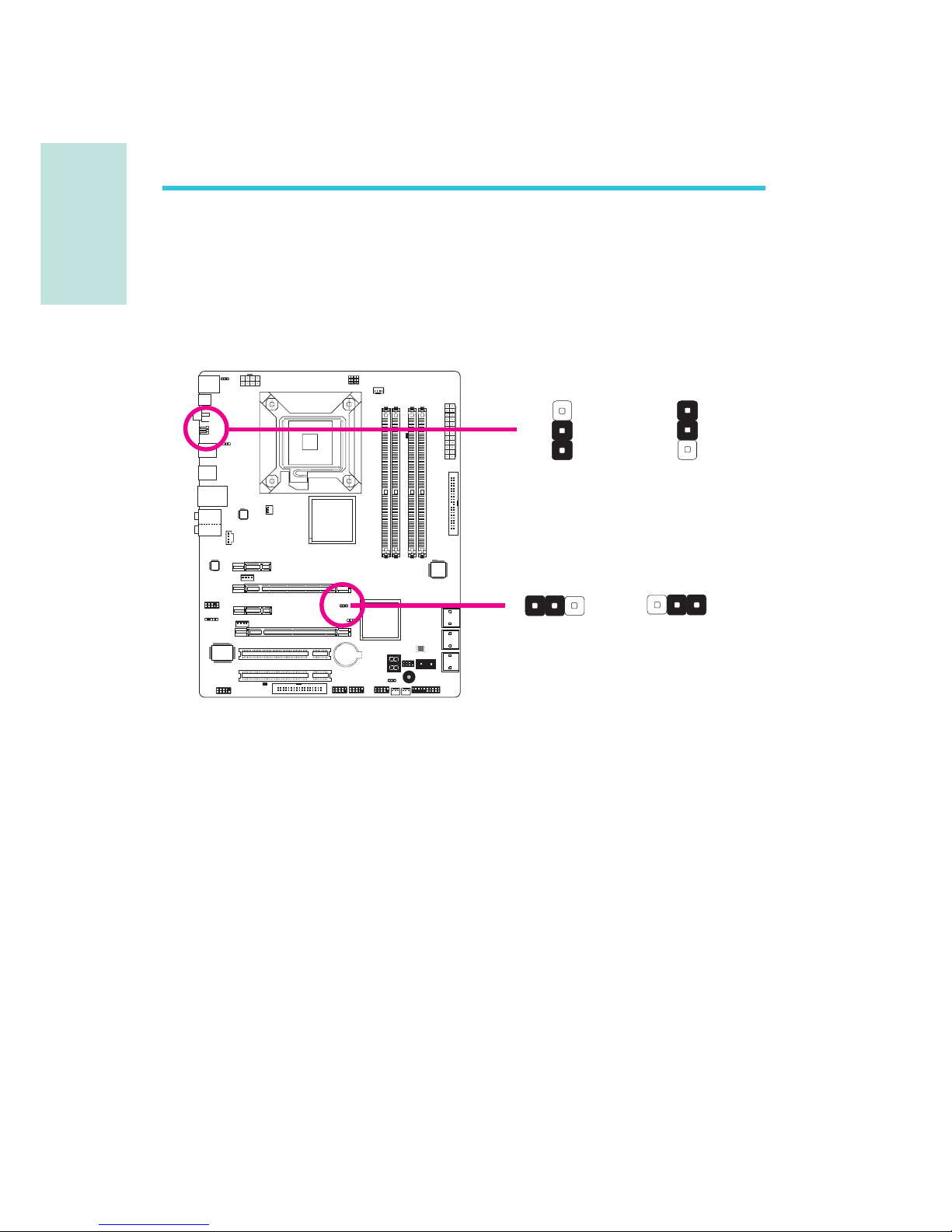
Cavalier
Si vous rencontrez les éléments suivants,
a) Données CMOS devenant corrompues
b) Vous avez oublié le superviseur ou le mot de passe utilisateur
c) Les réglages surcadencés dans le BIOS ont entraîné une instabilité
du système ou causés des problèmes de démarrage du système.
Vous devez reconfigurer le système aux valeurs par défaut stockées
dans la ROM BIOS.
JP8 est accessible depuis le panneau arrière du système.
Ceci vous
apporte la commodité de nettoyer le CMOS sans avoir à retirer le
couvercle du chassis.
Effacer les Données CMOS
Se débarrasser des données CMOS en utilisant les cavaliers
1-2 On: Normal
(défaut)
1-2 On: Normal
(défaut)
2-3 On:
Effacer les données
CMOS
2-3 On:
Effacer les données
CMOS
JP2
JP8
X
X
3
123
1
2
1
3
2
1
3
2
Page 35

F
Français
35
Français
Pour charger les valeurs par défaut dans la ROM BIOS, veuillez
suivre les étapes ci-dessous.
1. Débrancher le système et retirer le cordon d’alimentation.
2. Mettre les broches du JP2/JP8 2 et 3 sur ON Attendre quelques
secondes et remettre JP2/JP8 par défaut, broches 1 et 2 On.
3. Rebrancher maintenant le cordon d’alimentation et allumer le
système.
Page 36
Français
F
36
Français
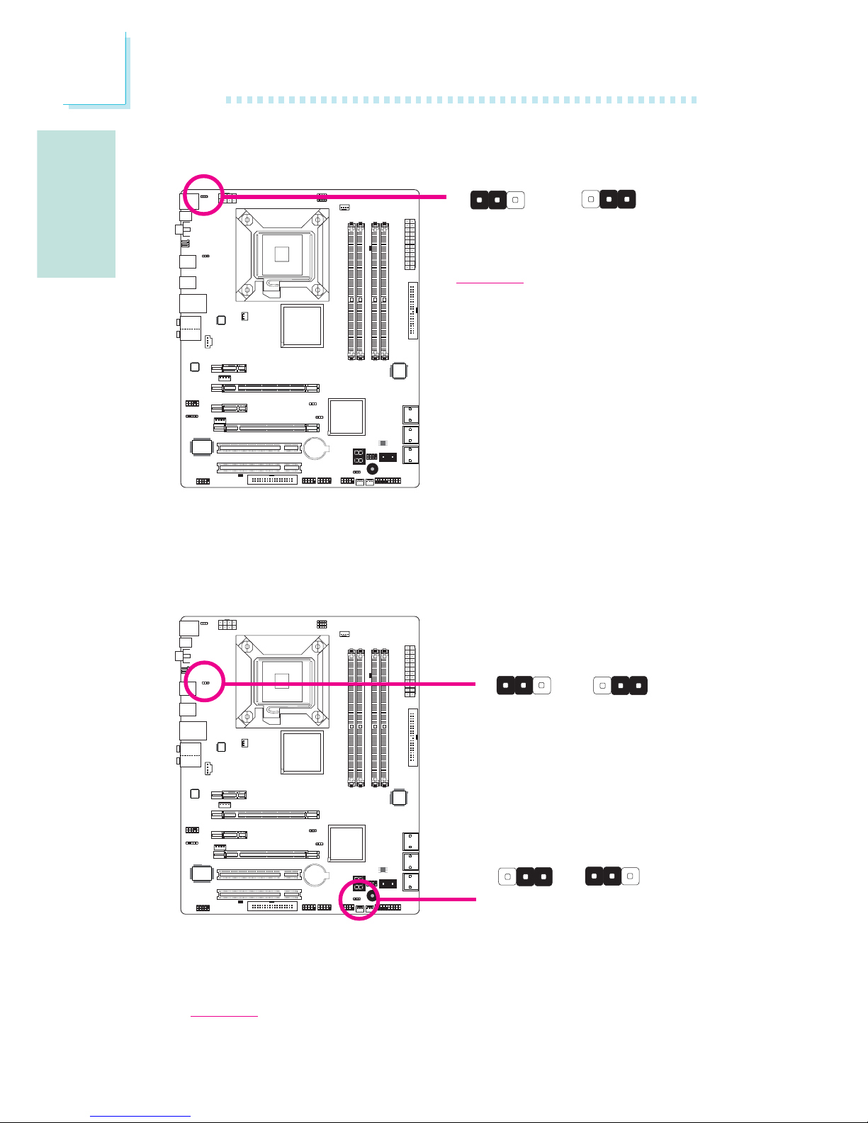
Sélectionner l’alimentation PS/2
En sélectionnant 5VSB, vous pourrez utiliser le clavier PS/2 ou la
souris PS/2 pour “réveiller” le système.
1-2 On: 5V
(
défaut)
Sélectionner l’alimentation USB
1-2 On: 5V
(
défaut)
Important:
La source d’alimentation 5VSB de
votre alimentation doit supportée
≥720mA.
2-3 On:
5VSB
1-2 On: 5V
(
défaut)
2-3 On: 5VSB
2-3 On:
5VSB
X
JP7
X
USB 6-11
(JP5)
X
USB 0-5
(JP6)
3
1231
2
312 312
31
2
312
En sélectionnant 5VSB, vous pourrez utiliser le clavier USB ou la
souris USB pour “réveiller” le système.
Important:
La source d’alimentation 5VSB de votre alimentation doit supportée ≥1,5(2
ports) ou ≥2 A(3 ou davantage de ports).
Page 37
F
Français
37
Français
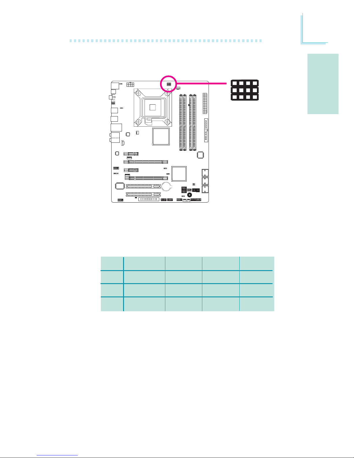
Par défaut, les trois cavaliers sont tous réglés avec les broches 1 et
2 On.Ce réglage permettra au système de fonctionner
automatiquement en fonction du FSB du processeur. Si vous désirez
modifier le réglage, veuillez vous référer au tableau ci-dessous.
JP17
JP18
JP19
Par processeur
1-2 On
1-2 On
1-2 On
FSB 800
2-3 On
3-4 On
2-3 On
FSB 1066
2-3 On
2-3 On
2-3 On
FSB 1333
2-3 On
2-3 On
3-4 On
Sélectionner le FSB du processeur
X
JP17
42
3
JP18
JP19
1
Page 38
Français
F
38
Français
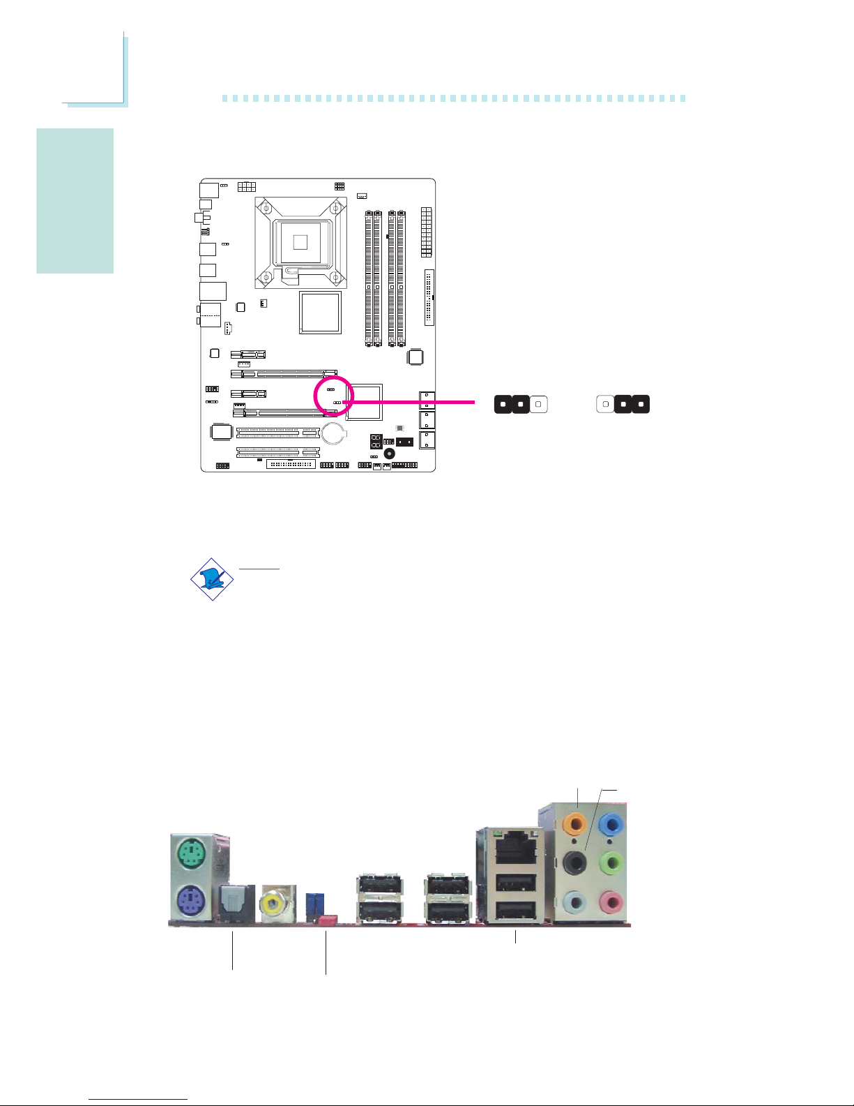
Ports I/O de l’arrière du Panneau
sortie optique
S/PDIF
USB 10-11
USB 6-7
sortie coaxial
RCA S/PDIF
Mic-in
Side R/L
Center/
Subwoofer
Rear R/L
Line-in
Front R/L
LAN
USB 8-9
Clear
CMOS
jumper
souris
PS/2
clavier PS/2
Réinitialisation de l’horloge temps réel secondaire
Lorsque la pile de l’horloge est enlevée, ce cavalier réinitialise la
capacité de gestion des octets du registre de l’horloge.
Note:
1. L’entrée SRTCRST# doit toujours être élevée lorsque toutes
les autres couches Power plane de l’horloge sont ON.
2. Dans le cas où la pile de l’horloge soit inopérante ou
manquante sur la plateporme la broche SRTCRST# doit
être montée avant la broche RSMRST#.
1-2 On: Normal
(défaut)
2-3 On:
RTC reset
X
JP12
1
3
2
13
2
Page 39
F
Français
39
Français
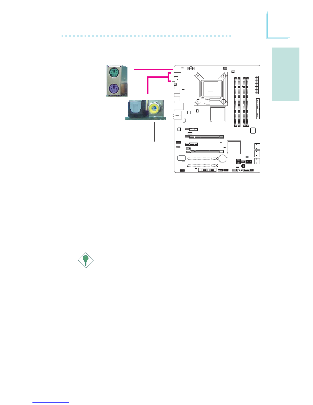
Ports Souris PS/2 et Clavier PS/2
Ces ports sont utilisés pour raccorder une souris PS/2 et un clavier
PS/2.
Prises coaxiale de RCA S/PDIF et optique de S/PDIF
Ces prises sont utilisées pour connecter les appareils de sortie audio
externes en utilisant les câbles coaxiaux et optique S/PDIF.
Important:
NE PAS utiliser un câble S/PDIF et RCA S/PDIF coaxial en
même temps.
Ports PS/2 et S/PDIF
W
PS/2 Mouse
PS/2 KB
optique
S/PDIF
coaxiale de
RCA S/PDIF
W
Page 40
Français
F
40
Français
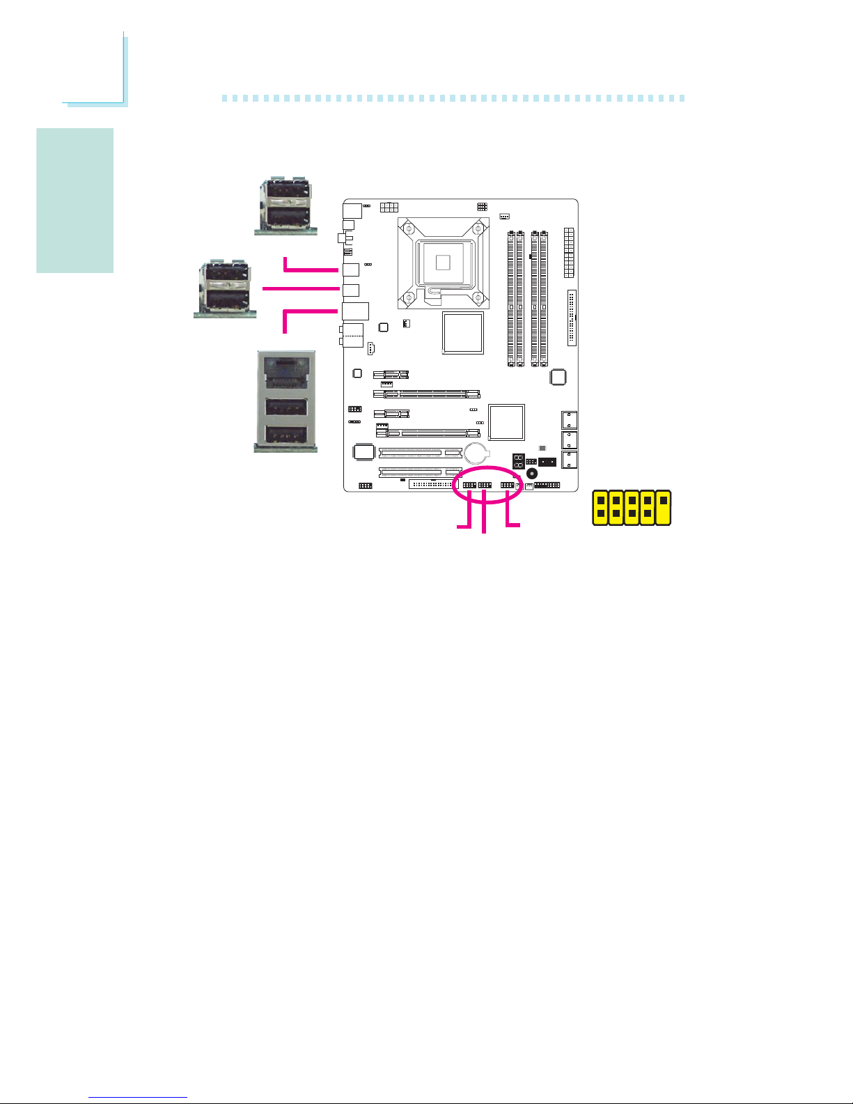
Ports USB et LAN
Ports USB
Les ports USB sont utilisés pour raccorder des appareils USB 2.0/
1.1. Les connecteurs 10 broches vous permettent de raccorder 6
autres ports USB 2.0/1.1. Vos ports USB peuvent être livrés montés
sur un support encartable. Installer le support encartable dans une
fente disponible à l’arrière du châssis du système et raccorder les
câbles des ports USB à ces connecteurs.
Ports LAN
Les ports LAN permettent à la carte système de se connecter à un
réseau local au moyen d’un concentrateur réseau.
1
VCC
-Data
+Data
GND
Key
VCC
-Data
+Data
GND
N. C.
2
10
9
W
USB 4-5
W
USB 0-1
USB 9
W
LAN
USB 8
USB 11
USB 10
USB 7
USB 6
USB 2-3
Page 41
F
Français
41
Français
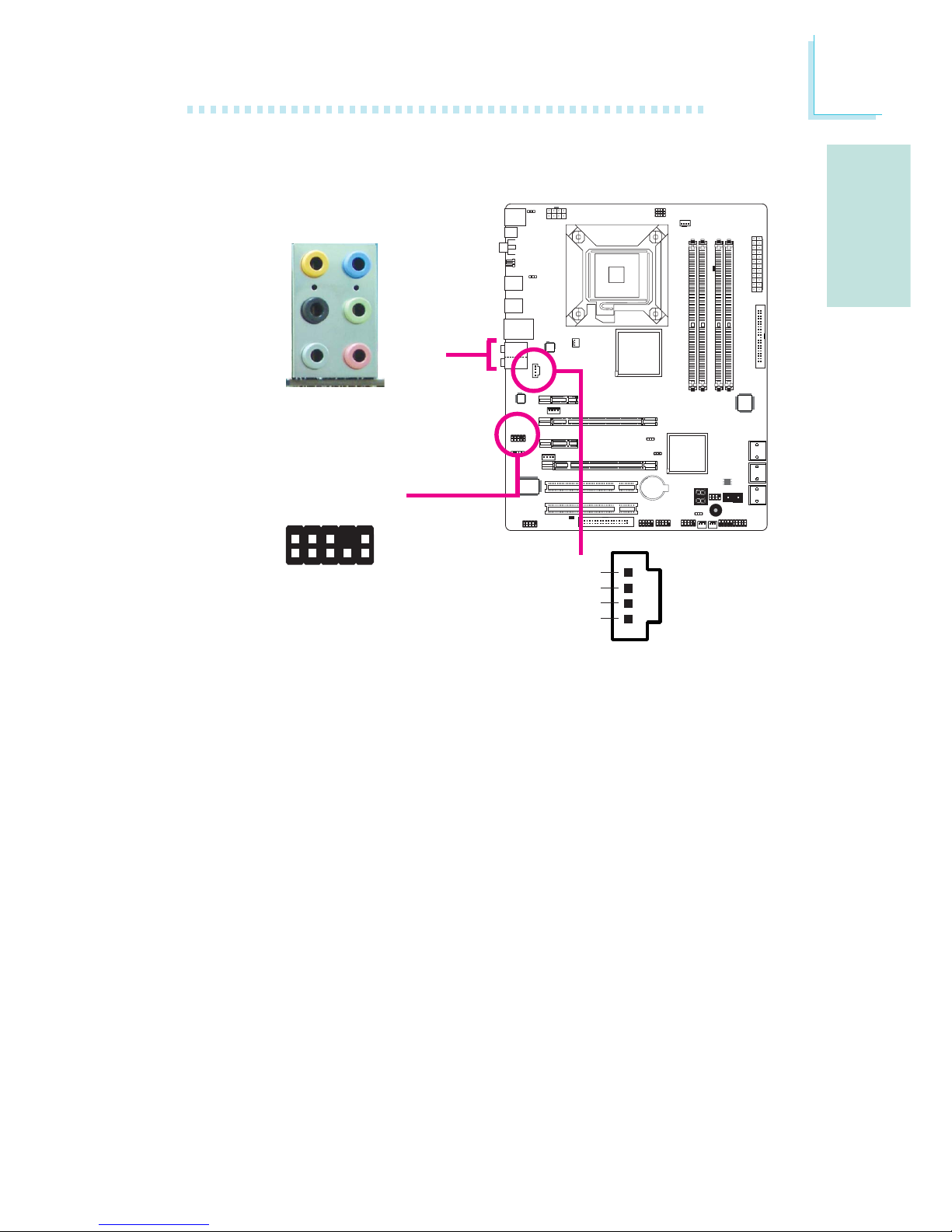
Audio et CD-In
Prise de caisson de basse/central (Center/Subwoofer) (orange)
Cette prise est utilisée pour se connecter aux haut-parleurs de
basse et centraux du système audio.
Prise arrière gauche/droite (noire)
Cette prise est utilisée pour se connecter aux haut-parleurs arrière
droits et gauches du système audio.
Prise de côté gauche/droite (grise)
Cette prise est utilisée pour se connecter aux haut-parleurs de côté
droits et gauches du système audio.
Prise entrée (bleue claire)
La prise est utilisée pour raccorder tous les appareils audio tels que
Hi-fi, lecteur CD, lecteur de bande magnétique, radio AM/FM,
synthéthiseur, etc..
W
W
Rear audio
Front audio
Front R/L
Line-in
Mic-in
Rear R/L
Center/
Subwoofer
Side R/L
1
2
10
Mic-L
Mic-R
Line-out-R
Front-sense
Line-out-L
GND
Presense-signal
Mic-jack-sense
Key
Line-out-jack-sense
9
4
1
Left audio channel
Right audio channel
Ground
Ground
W
CD-in
Page 42

Français
F
42
Français
Prise de sortie (Citron)
Cette prise est utilisée pour se connecter aux haut-parleurs avant
droits et gauches du système audio.
Prise entrée micro (rose)
Cette prise est utilisée pour connecter un microphone externe.
Connecteur audio frontal
Le connecteur audio frontal est utilisé pour raccorder les prises micro
d’entrée et les sorties de ligne (line-out) sur le panneau frontal de
votre système.
Connecteur d’entrée CD
Le connecteur d’entrée CD est utilisé pour recevoir les signaux audio
d’un lecteur CD-ROM, d’une carte TV ou MPEG.
Page 43
F
Français
43
Français
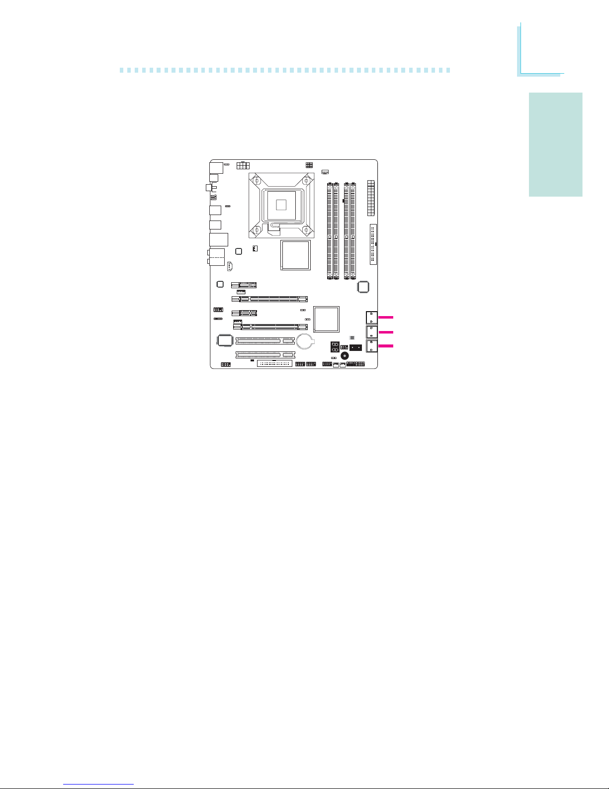
Les Connecteurs en Série ATA
Les connecteurs en série ATA (SATA) sont utilisés pour raccorder les
disques durs ATA en série. Relier une extrémité du câble en série
ATA au connecteur en série ATA et l’autre extrémité sur votre
appareil en série ATA.
Configuration du Système RAID
Se référer au chapitre RAID de ce manuel pour obtenir davantage
d‘informations sur la création d’un système RAID sur les disques
durs en série ATA.
Connecteurs I/O
SATA 2-3
SATA 0-1
SATA 4-5
Page 44
Français
F
44
Français
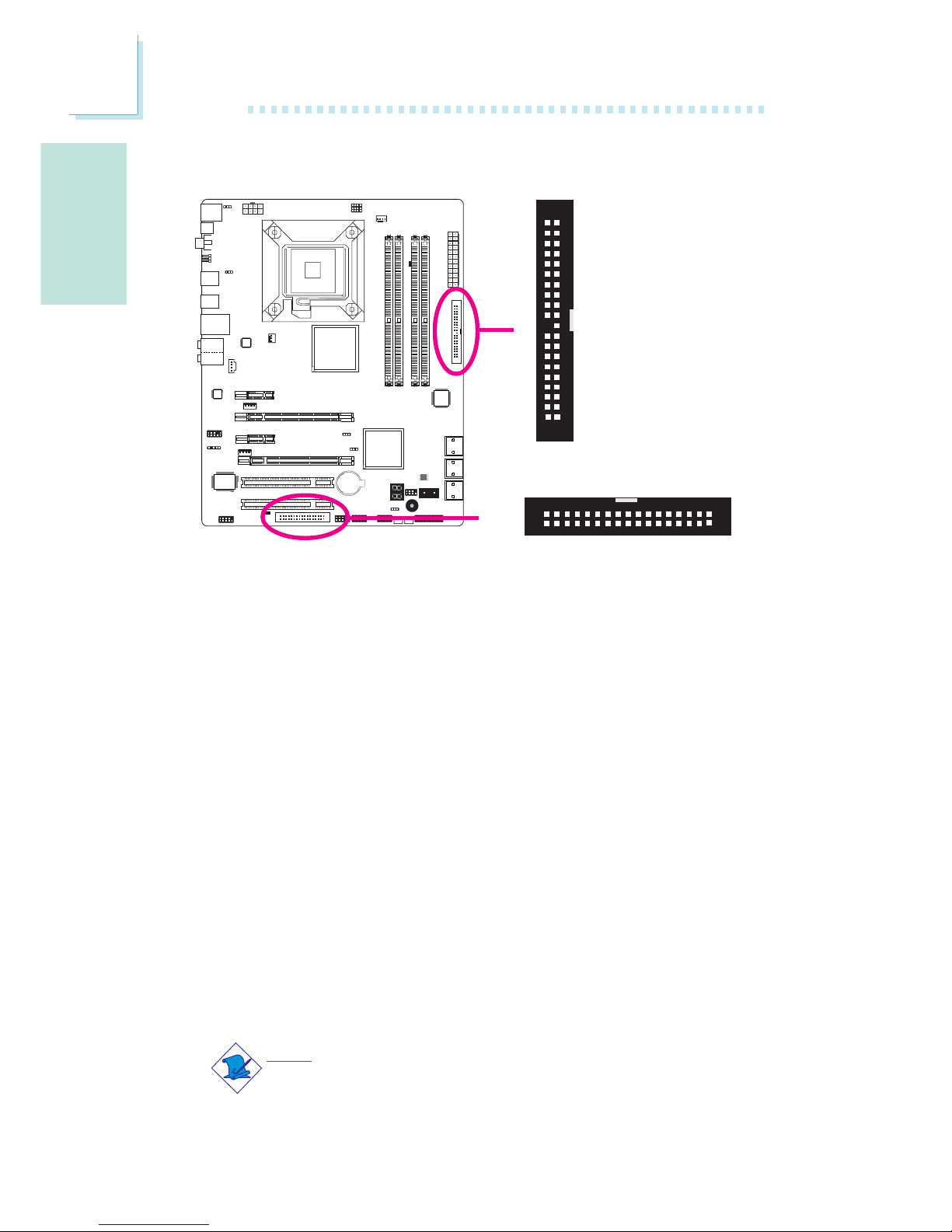
Connecteur de Lecteur de Disquettes et Connecteur IDE
Connecteur de Lecteur de Disquettes
Le connecteur de lecteur de disquettes est utilisé pour raccorder le
lecteur de disquettes. Il possède un mécanisme d’insertion
qui
empêche sa mauvaise installation. Insérer une extrémité du câble du
lecteur de disquette dans ce connecteur et l’autre dans le lecteur de
disquette. Le bord coloré du câble devrait être aligné avec l’ergot 1
de ce connecteur.
Connecteur de Disque dur IDE
Le connecteur de disque dur IDE est utilisé pour raccorder 2
disques IDE. Il possède un mécanisme d’insertion
qui empêche la
mauvaise installation du cable IDE. Un câble IDE comporte 3
connecteurs, un qui se branche sur ce connecteur et les deux autres
qui se connectent sur les appareils IDE. Le connecteur à l’extrémité
du câble est pour le disque maître et celui au milieu du câble est
pour l’esclave. Le bord coloré du câble devrait être aligné avec
l’ergot 1 de ce connecteur.
Note:
Lors de l’utilisation des disques dur IDE, l’un doit être assigné
Maître et l’autre esclave. Suivre les instructions fournies par le
fabricant de disques durs pour mettre les cavaliers et/ou les
commutateurs sur les disques durs.
X
40
39
21
X
IDE
FDD
34
33
1
2
Page 45
F
Français
45
Français
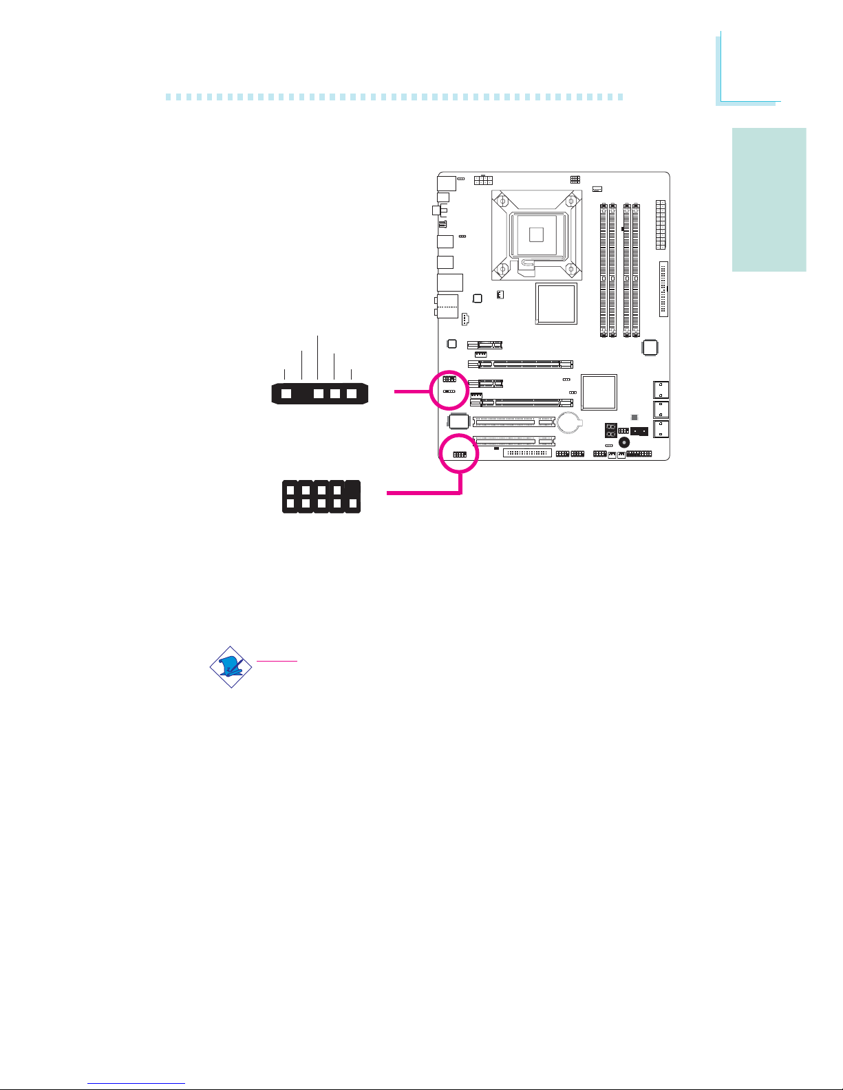
Connecteurs IrDA et en Série (COM)
Connecteur IrDA
Ce connecteur est utilisé pour raccorder un module IrDA.
Note:
La séquence de la fonction des broches (signal) sur certains
câbles IrDA peut être inversée à partir de la fonctionnalité
définie sur la carte système. S’assurer de relier le connecteur du
câble sur le connecteur IrDA selon les fonctions de leurs
broches.
Il se peut que vous deviez installer les disques dans votre système
d’exploitation convenants à l’utilisation de la fonctionnalité IrDA Se
référer au manuel de votre système d’exploitation ou à la documentation pour obtenir davantage d’informations.
Connecteur en Série (COM)
Le connecteur en série (COM) est utilisé pour raccorder les modems, les imprimantes en série, les terminaux d’affichage à distance
ou autres appareils en série. Votre port COM peut être livré monté
W
1
9
2
CD
TD
RD
DTR
GND
RTS
DSR
CTS
RI
COM
15
VCC
N. C.
IRRX
Ground
IRTX
IrDA
X
Page 46
Français
F
46
Français
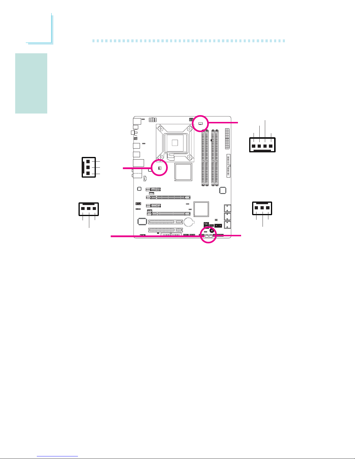
Connecteurs de Ventilateur de Refroidissement
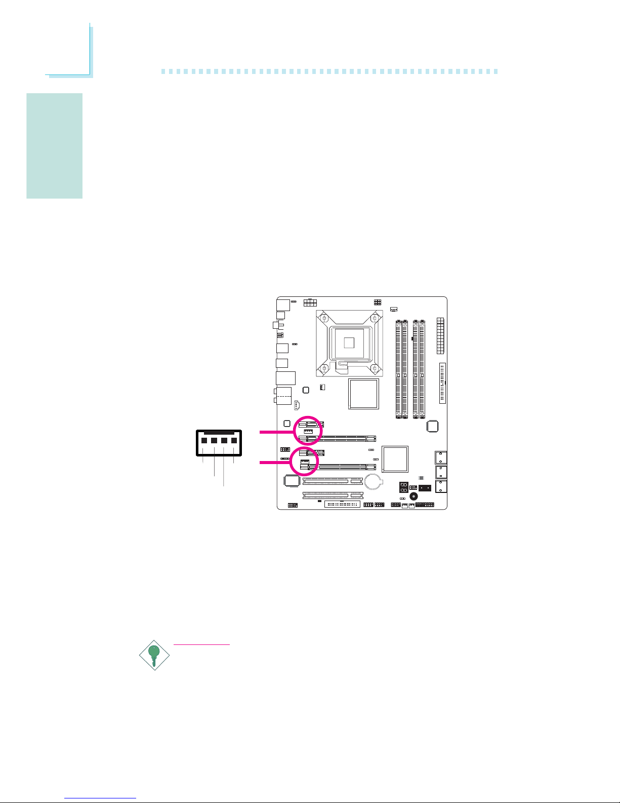
Ces connecteurs de ventilateur sont utilisés pour raccorder les
ventilateurs de refroidissement. Les ventilateurs de refroidissement
fournissent une ventilation adéquate à l’intérieur du châssis afin
d’empêcher toute surchauffe du processeur et des composants de la
carte système.
sur un support encartable. Installer le support encartable dans une
fente disponible à l’arrière du châssis du système et raccorder le
câble du port en série à ce connecteur. Le bord coloré du câble
devrait être aligné avec l’ergot 1 de ce connecteur.
X
X
CPU fan
Chassis fan
System fan
X
NB fan
1
3
Sense
Power
On/Off
4
1
Sense
Power
Ground
Speed
Control
3
1
Ground
Power
Sense
X
3
1
Ground
Power
Sense
Page 47
F
Français
47
Français
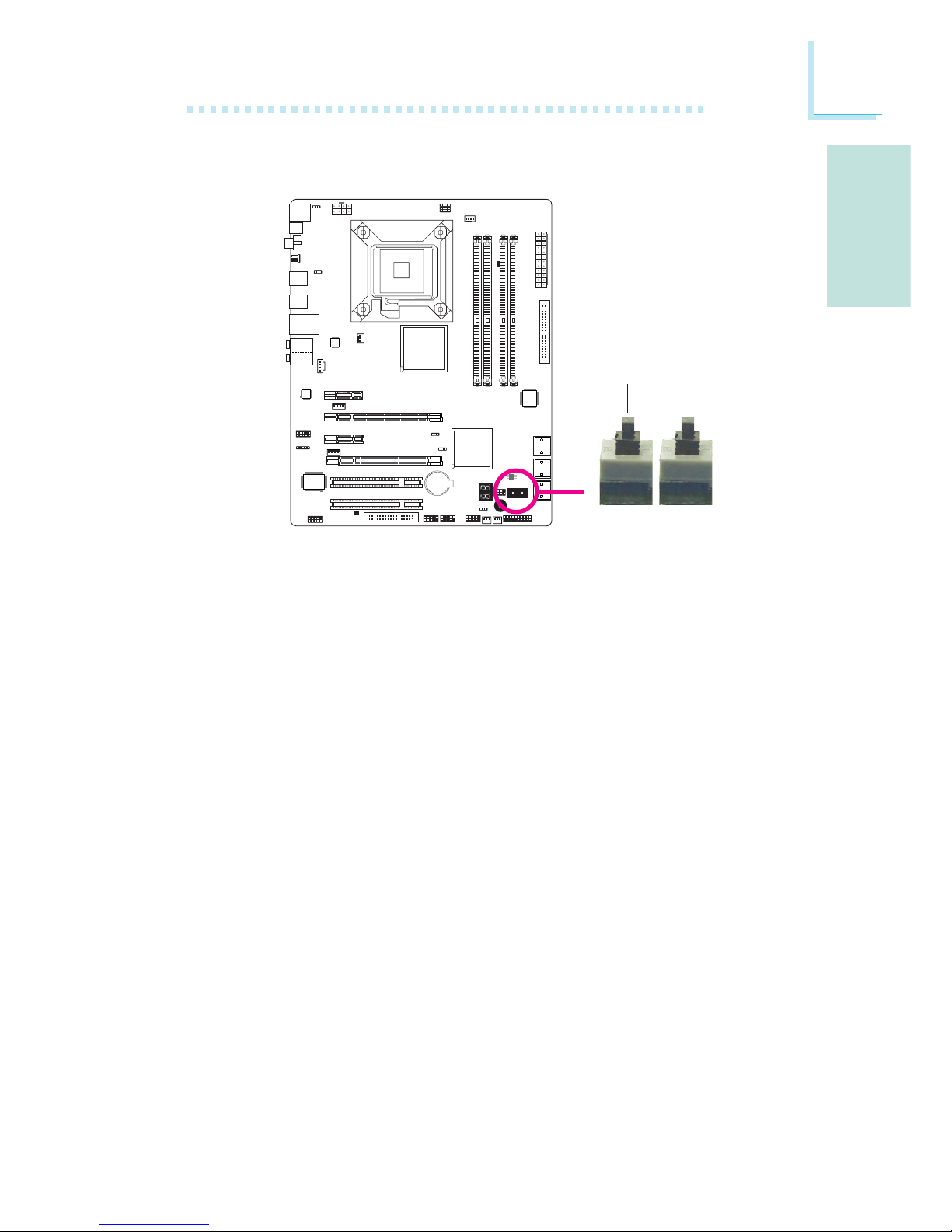
La présence des commutateurs d’alimentation et de réinitialisation
sur la carte système est conviviale et particulièrement pour les
utilisateurs étant bricoleurs. Ils sont très pratiques pour allumer ou
réinitialiser le système tout en ajustant la carte système avant
l’installation sur le châssis.
Commutateurs à Touche EZ
Réinitialisation
Alimentation
X
Power
Page 48
Français
F
48
Français
Voyants DEL
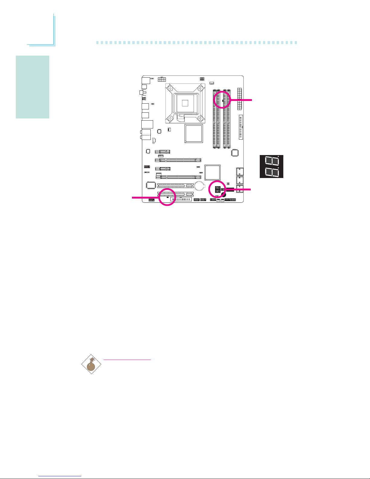
Voyant DEL d’alimentation DRAM
Ce voyant DEL s’allumera lorsque le système est allumé.
Voyant DEL d’alimentation à l’état de Veille
Ce voyant DEL s’allumera lorsque le système est en mode veille.
Voyant DEL de Diagnostic
Le voyant DEL de diagnostic affiche les codes POST. POST (tests
automatiques d’alimentation) qui est contrôlé par le BIOS est
effectué à chaque fois que le système est allumé. ¨POST détectera le
statut du système et de ses composants. Chaque code affiché sur le
voyant DEL correspond à un certains statut du système.
Avertissement:
Lorsque le voyant DEL d’alimentation DRAM et/ou
d’alimentation à l’état de veille sont rouge, cela indique que le
courant passe dans les supports DIMM et/ou dans les fentes
PCI. Eteindre le PC et débrancher le cordon d’alimentation avant
d’installer les modules mémoire ou les cartes d’extension. Un
échec à effectuer ceci peut entraîner des dégâts graves à la
carte mère et ses composants.
.
.
.
.
.
.
.
.
Voyant DEL
d’alimentation
DRAM
Voyant DEL
d’alimentation à
l’état de veille
Voyant DEL
de diagnostic
Page 49
F
Français
49
Français
Connecteurs d’alimentation
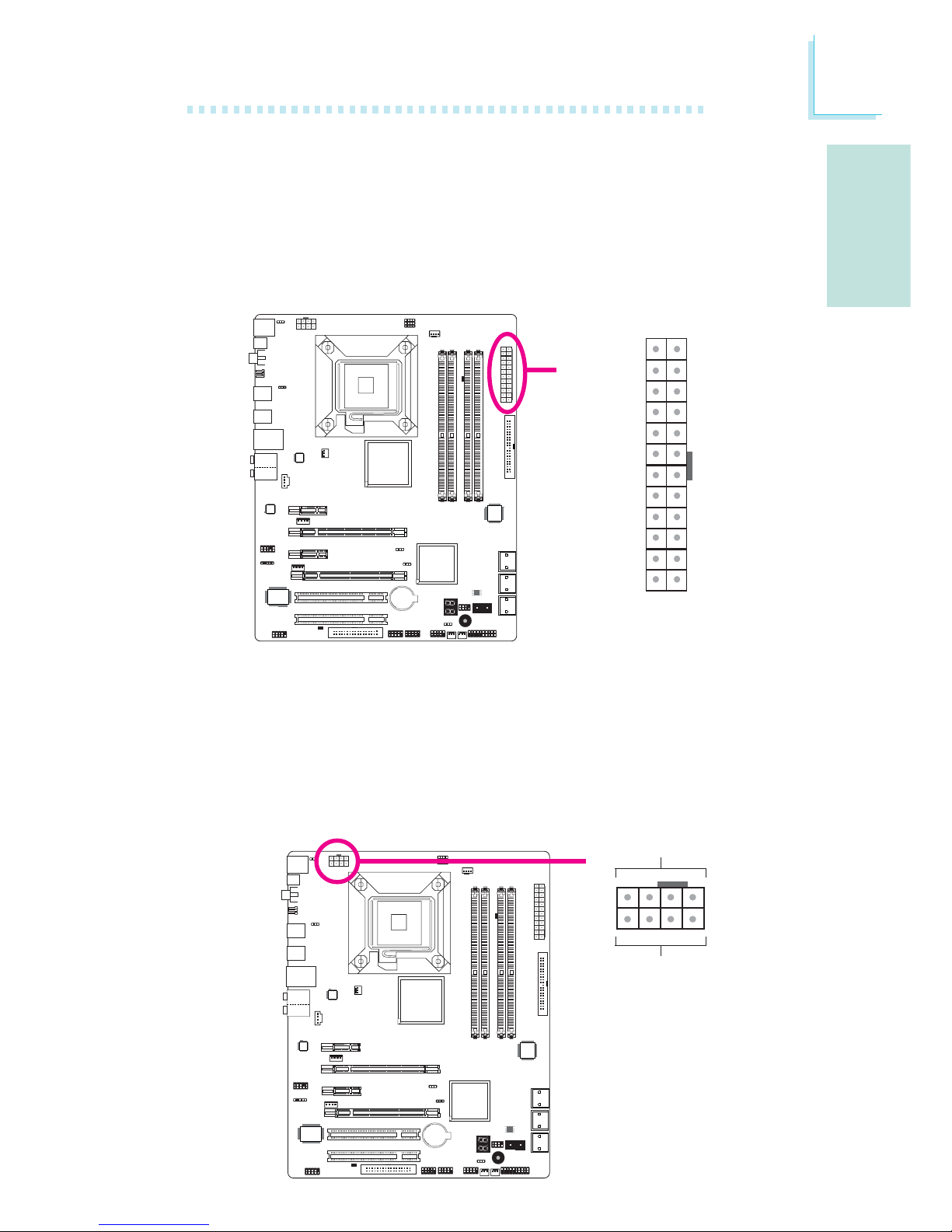
Utiliser une alimentation électrique conforme à la version 1.1 du
guide d’alimentation électrique ATX12V. Une unité d’alimentation
électrique ATX12V possède un connecteur d’alimentation principale
ATX à 24 broches qui doit être inséré dans ce connecteur.
Votre unité d’alimentation électrique peut être livrée avec un
connecteur d’alimentation 12V à 4 ou 8 broches. L’alimentation 12V
permet la fourniture de courant 12VDC en direction du module de
régulation de tension du processeur (VRM - Voltage Regulator Module). Si disponible, il est préférable d’utiliser une alimentation 8
broches, sinon, raccorder une alimentation 4 broches à ce connecteur.
X
131
12 24
+3.3VDC
+3.3VDC
COM
+5VDC
COM
+5VDC
COM
PWR_OK
+5VSB
+12VDC
+12VDC
+3.3VDC
+3.3VDC
-12VDC
COM
PS_ON#
COM
COM
COM
NC
+5VDC
+5VDC
+5VDC
COM
X
+12V
Ground
14
58
Page 50
Français
F
50
Français
La carte système nécessite une alimentation minimale de 300 Watts
pour pouvoir fonctionner. La configuration de votre système
(alimentation du processeur, cartes d’extension, périphériques etc.)
peut dépasser la puissance minimale requise. Pour s’assurer que la
puissance minimale soit fournie, nous vous conseillons fortement
d’utiliser une alimentation minimale de 400 Watts (ou davantage).
Important:
Une puissance insuffisante fournie au système peut entraîner
une instabilité ou un mauvais fonctionnement des cartes
d’extension et des périphériques. Le calcul de la puissance
approximative requise par le système est important pour
garantir que l’alimentation soit suffisante pour la consommation
du système.
Les connecteurs d’alimentation de l’unité d’alimentation électrique
sont conçus pour s’adapter aux connecteurs à 24 et 8 broches
seulement dans une direction. S’assurer d’observer la bonne orientation avant de brancher les connecteurs.
Les connecteurs d’alimentation de type FDD sont des connecteurs
supplémentaires d’alimentation. Si vous utilisez plus d’une carte
graphique, nous vous conseillons de brancher les câbles
d’alimentation depuis votre unité d’alimentation électrique sur des
connecteurs d’alimentation de 5V/12V. Ceci donnera plus de stabilité
à tout le système. La carte système fonctionnera toujours même si le
connecteur d’alimentation supplémentaire n’est pas raccordé.
1
4
+5V
+12V
Ground
Ground
Page 51

F
Français
51
Français
Redémarrage du PC
Normalement vous pouvez éteindre le PC en :
1. Appuyant sur le bouton d’alimentation sur le panneau frontal du
chassis.
ou
2. En appuyant sur le commutateur d’alimentation se trouvant sur la
carte système (note : toutes les cartes systèmes ne possèdent
pas ce commutateur)
Si, pour quelque raison que ce soit, vous devez éteindre l’alimentation
du PC, éteindre l’alimentation ou débrancher le cordon d’alimentation.
Veuillez noter que si vous désirez le redémarrer de suite, suivez les
étapes suivantes :
1. Le temps de déchargement de l’électricité dépend des
alimentations électriques. Le temps de déchargement dépend
entièrement de la configuration du système telle que le nombre
de Watt de l’alimentation, de la séquence de l’alimentation ainsi
que du nombre d’appareils périphériques reliés au système. Pour
ces raisons nous conseillons fortement d’attendre que le voyant
DEL de veille (se référer à la section « voyants DEL » de ce
chapitre pour la localisation de ce voyant) s’éteigne.
2. Une fois le voyant DEL de veille éteint, attendre 6 secondes avant
d’allumer le PC.
Si la carte système est déjà montée dans un châssis qui
apparemment ne laissera pas entrevoir le voyant DEL de veille,
attendre 15 secondes avant de restaurer les connexions
électriques. 15 secondes est environ le temps que prendra le
voyant DEL pour s’éteindre et le temps nécessaire avant la
restauration de l’alimentation.
Ceci garantit une protection et empêche les dégâts graves éventuels
à la carte mère et à ses composants.
Page 52
Français
F
52
Français
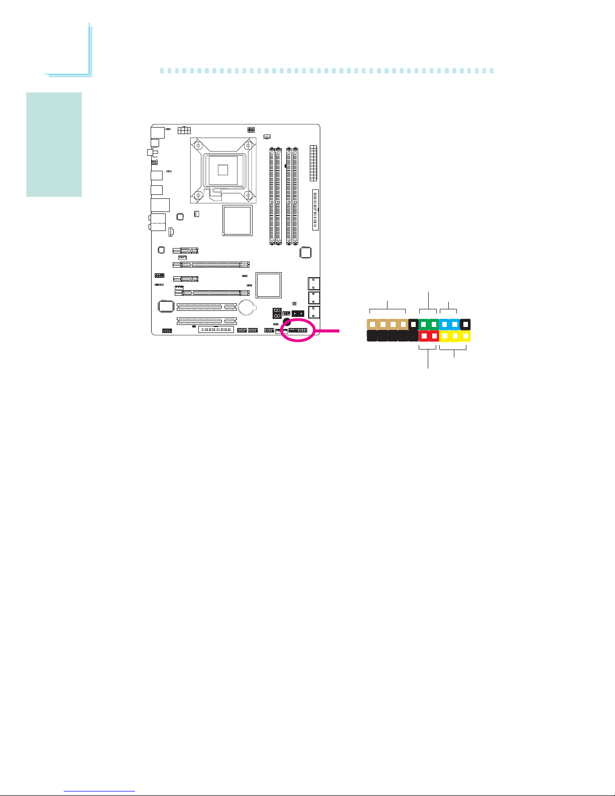
Connecteurs Frontaux du Panneau
HD-LED: Voyant DEL IDE Principal/Secondaire
Ce voyant DEL s’allumera lorsqu’on accède au disque dur.
RESET: Commutateur de Réinitialisation
Ce commutateur vous permet de redémarrer sans avoir à éteindre
le système et par conséquent en permettant une durée de vie de
l’alimentation ou du système prolongée.
SPEAKER: Connecteur du Haut-parleur
Il se connecte au haut parleur installé dans le châssis du système.
ATX-SW: Commutateur d’alimentation ATX
Dépendant des réglages à l’intérieur du BIOS, ce commutateur est
un « bouton d’alimentation à deux fonctions » qui permettra à votre
système d’entrer en mode Soft-Off ou Suspend.
X
1
2
19
20
HD-LED
RESET
SPEAKER
PWR-LED
ATX-SW
Page 53
F
Français
53
Français
PWR-LED: Voyant DEL d’alimentation / état de veille
Ce voyant DEL s’allumera lorsque le système est allumé. Lorsque le
système est sur le statut S1 (POS – alimentation suspendue) ou S3
(STR – suspendue dans la RAM), il clignotera toutes les secondes.
Note:
Si le système n’a pas démarré et que le voyant DEL
d’alimentation/veille ne s’est pas allumé après le démarrage,
cela peut indiquer que le processeur ou le module n’ont pas
été installés correctement. Veuillez vous assurer qu’ils soient
correctement insérés dans leur support.
Pin
3
5
14
16
8
10
18
20
7
9
13
15
17
19
2
4
6
HD-LED
(Primary/Secondary IDE LED)
Reserved
ATX-SW
(ATX power switch)
Reserved
RESET
(Reset switch)
SPEAKER
(Speaker connector)
PWR-LED
(Power/Standby LED)
Pin Assignment
HDD LED Power
HDD
N. C.
N. C.
PWRBT+
PWRBT-
N. C.
N. C.
Ground
H/W Reset
Speaker Data
N. C.
Ground
Speaker Power
LED Power (+)
LED Power (+)
LED Power (-) or Standby Signal
Page 54
Français
F
54
Français
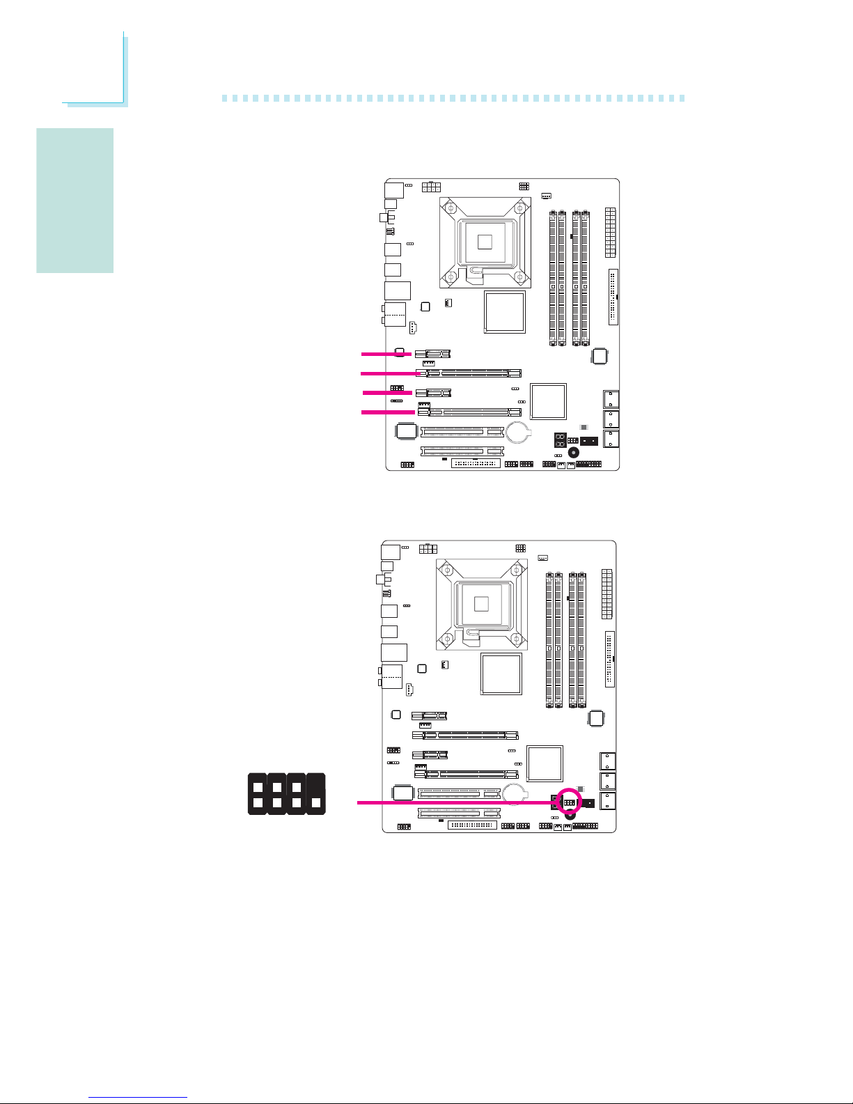
Fentes PCI Express
PCI Express x1
PCI Express x16
PCI Express x16
PCI Express x1
Connecteur de Download Flash BIOS Connector
W
1
GROUND
2
8
7
SPI_VCC3
SPI_CS0B
SPI_MIS0
SPI_HOLD#
SPI_CLK
SPI_MOSI
Page 55

F
Français
55
Français
La puce ICH10R permet la configuration du système RAID sur
disques durs ATA. Elle supporte les systèmes RAID 0, RAID 1,
RAID 0+1 et RAID 5.
Niveaux du Système RAID
RAID 0 (matrice de disque à “0” erreur de tolérance)
RAID 0 utilise deux nouveaux disques durs identiques pour lire et
graver en blocs parallèles. Les données sont divisées en bandes et
chaque bande est gravée alternativement d’un disque à l’autre. Ceci
améliore la performance I/O des disques sur les différents canaux,
cependant aucune tolérance d’erreur n’est admise. Un disque
défaillant résultera en une perte des données dans la matrice.
RAID 1 (matrice de disque à écriture mirroir à tolérance
d’erreur)
RAID 1 copie et conserve une image identique des données d’un
disque à l’autre. Si un disque fonctionne incorrectement, le logiciel de
gestion de la matrice envoie toutes les applications en direction de
l’autre disque puisqu’il contient une copie complète des données du
disque. Ceci améliore la protection des données et accroît la
tolérance des erreurs dans tout le système. Utiliser deux nouveaux
disques durs ou un disque existant et un nouveau disque dur mais
la taille du nouveau disque dur doit être identique ou supérieure à
celle de celui existant.
RAID 0+1 (bande et mirroir)
RAID 0+1 est une combinaison de données mirroir et de bandes
de données apportant les avantages des systèmes RAID 0 et RAID
1. Utiliser quatre nouveaux disques durs ou un disque existant et
trois nouveaux disques pour cette configuration.
RAID 5
RAID 5 répartit en écriture les données et les informations
concernant la parité sur les disques durs. Il est insensible aux
défaillances et permet d’obtenir de bien meilleures performances des
disques durs ainsi qu’une capacité de stockage accrue.
Chapitre 3 - RAID
Page 56

Français
F
56
Français
Se référer au chapitre 2 pour obtenir davantage de détails sur la
connexion des disques durs en série ATA.
Important:
1. S’assurer d’avoir installé les disques en série ATA et d’avoir raccordé les
câbles de données sinon vous ne pourrez entrer dans l’utilitaire BIOS RAID.
2. Faire très attention aux câbles et particulièrement en créant le système RAID.
Un câble endommagé détériorera tout le processus d’installation et le SE. Le
système ne démarrera pas et vous perdrez toutes les données des disques
durs. Veuillez prêter attention à cet avertissement car il n’existe aucun moyen
de récupérer les informations.
Etape 2 : Configurer le disque ATA en série dans le BIOS
1. Allumer le système et appuyer sur <Del> pour rentrer dans le
menu principal du BIOS.
2. Sélectionner le sous menu des périphériques intégrés - sur la
partie de puce correspondant au disque IDE du BIOS
3. Configurer le disque ATA en série dans les champs appropriés.
4. Appuyer sur <Esc> pour retourner au menu principal de l’utilitaire
d’installation du BIOS. Sélectionner “Save & Exit Setup” et
appuyer ensuite sur <Enter>.
5. Taper <Y> et appuyer sur <Enter>.
6. Redémarrer le système.
Etape 3 : Configurer le système RAID dans le BIOS RAID
Lorsque le système démarre et que tous les disques durs ont été
détectés, le message de statut du BIOS RAID apparaîtra. Appuyer
sur la touche <Ctrl>+<I> pour entrer dans l’utilitaire. L’utilitaire
vous permet de créer un système RAID sur des disques durs en
série ATA.
Etape 1 : Raccorder les disques durs en série ATA.
Réglages
Pour activer la fonctionnalité RAID, les réglages suivants sont
nécessaires:
1. Raccorder les disques durs en série ATA.
2. Configurer le disque ATA en série dans le BIOS.
3. Configurer les systèmes RAID dans le BIOS RAID.
4. Installer le driver RAID lors de l’installation du SE (système
d’expl
ion.
).
5. Installer le gestionnaire de stockage Intel.
Page 57

F
Français
57
Français
Etape 4 : Installer le driver RAID lors de l’installation du SE (système
d’explion.).
Le driver RAID doit être installé lors de l’installation de Windows
®
XP ou de Windows® 2000 en utilisant la méthode d’installation F6.
Ceci est nécessaire afin d’installer le SE sur un disque dur ou sur un
volume RAID lors du mode RAID ou sur un disque dur lors du
mode AHCI.
1. Lancer l’installation de Windows en démarrant depuis le CD
d’installation.
2. Appuyer sur <F6> lors de la demande dans la ligne de statut en
utilisant la touche F6
si vous avez besoin d’installer une troisième
partie SCSI ou lors d’un message du driver RAID.
3. Appuyer sur <S> pour « spécifier un appareil supplémentaire ».
4. A ce moment on vous demandera d’insérer une disquette
contenant le driver RAID. Insérer la disquette contenant le driver
RAID.
5. Localiser le lecteur dans lequel vous avez inséré la disquette et
sélectionner le système RAID ou le contrôleur AHCI
correspondant à votre installation du BIOS. Appuyer sur <Enter>
pour confirmer.
Vous avez réussi à installer le driver. Cependant vous devez
continuer à installer le SE. Laisser la disquette dans le lecteur de
disquette jusqu’à ce que le système rédémarre tout seul car lors de
l’installation de Windows les fichiers seront copiés depuis la disquette
sur les dossiers d’installation de Windows. Une fois les fichiers
copiés lors de l’installation de Windows, retirer la disquette afin de
laisser l’ordinateur redémarrer après l’installation de Windows.
Page 58

Français
F
58
Français
Etape 5:Installer le gestionnaire de stockage Intel
Le gestionnaire de stockage Intel Matrix peut être installé depuis
Windows.Il permet de gérer le volume RAID (créer, supprimer,
migrer) depuis le système d’exploitation. Il affichera également des
informations utiles concernant le volume RAID et l’appareil SATA.
L’interface utilisateur, la barre d’icône et le moniteur permettent de
surveiller le statut du volume RAID et/ou des lecteurs SATA. Elle
permet d’obtenir des performances accrues et la gestion de la
puissance du sous système de stockage.
1. Insérer le CD dans le lecteur CD-ROM.
2. Sur le côté gauche de l’écran autorun, cliquer sur l’icône
“CHIPSET”.
3. Cliquer sur “Intel(R) Matrix Storage Manager” sur le menu principal.
4. Suivre les étapes indiquées sur l’écran en cliquant « next » à
chaque fois qu’une étape est terminée.
Page 59
G
Deutsch
59
Deutsch
Kapitel 1 - Spezifikation
Prozessor
Chipset
Systemspeicher
Expansion Schlitz
BIOS
Audio
LAN
IDE
Serial ATA mit RAID
• LGA 775 CPU Einfaßung für:
- Intel® CoreTM2 Quad und Intel® CoreTM2 Duo
• Intel Erhöhten Technologie Des Gedächtnis-64 (EMT64T)
• Erhöhten Intel SpeedStep Technologie (EIST)
• Intel, das Technologie Hyper-Verlegt (Intel Hyper-Threading)
• Stützt 1333/1066/800MHz FSB
• Intel
®
chipset
- Nordbrücke:
Intel® P45 Express chipset
Intel® schneller Speicherzugrifftechnologie
- Südbrücke: Intel® ICH10R
• 4 240-pin-Steckplätze DDR2 DIMM
• Moduln 667/800 MHz
• Bis zum 12.8GB/s-Bandbreite.
• 128-bit – Speiher mit den zwei Kanälen
• Bis zum 8GB-Systemspeicher
• DIMMs ohne Dämpfer x8 und x16 DIMMs
• 2 PCI Express (Gen 2) x16-Einbauplätzen (PCIE 2 und PCIE 4)
- 2-way CrossFire: x8 (PCIE 2) + x8 (PCIE 4)
- 1 grafikkarte: x16 (PCIE 2/PCIE 4)
• 2 PCI Express x4-Einbauplätzen (PCIE 2)
• 2 PCI-Einbauplätzen
• Award BIOS
• 8MB SPI Flash BIOS
• CMOS Reloaded
• Realtek ALC885 8-Kanal-Hohe-Definition-audio-CODEC
• DAC SNR/ADC SNR von 106dB/101dB
• Lossless zufriedene Schutzvollwegtechnologie
• S/PDIF-Aus optischen und S/PDIF-Aus coaxial RCA Schnittstelle
• Marvell 88E8053 PCIE Gigabit LAN
• Völlig gefällig zu IEEE 802.3 (10BASE-T), 802.3u (100BASETX) und 802.3ab (1000BASE-T) standards
• JMicron JMB368 PCI ausdrücklich zum PATA Wirt Steuerpult
• Stützt bis 2 Ultra DMA 33/66/100Mbps IDE Vorrichtungen
• Intel Matrix Storage technology
• 6 serielle Serial ATA-Ports
• SATA bis zu 3Gb/s schnell
• RAID 0, RAID 1, RAID 0+1 und RAID 5
Page 60
Deutsch
G
60
Deutsch
Porte an der
Rückwand
Internes I/O
Energie
Management
Kleinteilmonitor
PCB
• 1 Mini-DIN-6-Anschluß für eine PS/2-Maus
• 1 Mini-DIN-6-Anschluß für eine PS/2-Tastatur
• 1 S/PDIF optischen-Anschlüsse
• 1 S/PDIF coaxial RCA-Anschlüsse
• 6 USB 2.0/1.1-Anschlüsse
• 1 RJ45 LAN-Anschlüsse
• Center/subwoofer, rear R/L und side R/LAudio-Anschlußbuchsen
• Line-in, line-out und mic-in Audio-Anschlußbuchsen
• 3 Anschlußfassung für 6 zusätzliche externe USB 2.0-Anschlüsse
• 1 Anschluß für eine externe serieller DB-9-Anschluß
• 1 Front-Audioanschluss
• 1 interne Audioanschlüsse (CD-in)
• 1 IrDA-Anschluß
• 6 Serial-ATA-Anschlüsse
• 1 IDE-Anschlüsse
• 1 Floppy-Anschlüsse
• 1 Anschlußstecker für das ATX-Netzgerät 24-pin
• 1 Anschlußstecker für das ATX-Netzgerät 8-pin 12V
• 2 4-polige 5V/12V Netzstecker (für FDD)
• 1 Vorderseite Füllung Anschlüsse
• 4-ventilator-Anschlüsse
• 1-download-flash-BIOS-Anschlüsse
• 1 diagnostischen Außenindikatoren
• EZ Umschaltern (der Knopf der Speisung und des Auslasses)
• ACPI und OS Directed Power Management
• ACPI STR (Suspend to RAM) funktion
• Wecken bei Betätigung der PS/2 Tastatur/Maus
• Wecken bei USB-Tastatur/Maus
• Wecken bei Klingeln und Wecken des Systems durch das Netzwerk
• RTC-Taktgeber zum Einschalten des Systems
• Wiederherstellung der Wechselstromversorgung nach einem
Ausfall
• Überwachung der Temperatur des CPU / Systems /
Nordbrücke sowie Warnsignal bei Überhitzung
• Überwachung der Spannungen des Vcore/Vdimm/Vnb/VCC5/
12V/V5sb/Vbat
• Überwachung der Geschwindigkeit des Ventilators
• Prozessor-Shutz - Die Ausschaltung bei der Überhitzung – die
automatische Ausschaltung des Computers bei der Überhitzung
• 4 layers, ATX Formfaktor
• 24.5cm (9.64") x 30.5cm (12")
Page 61
G
Deutsch
61
Deutsch
Kapitel 2 - Installieren des Hardware
Jumper
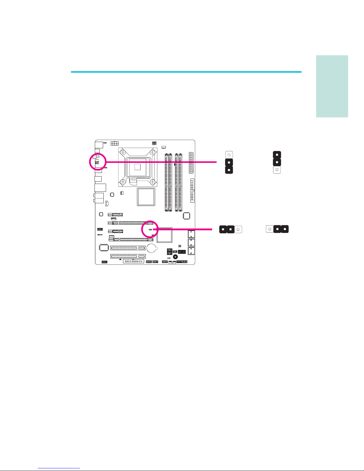
Sollten Sie eins der folgenden Probleme haben,
a) die CMOS Daten sind beschädigt.
b) Sie haben das Supervisor oder User Passwort vergessen.
c) die Übertaktungseinstellungen im BIOS haben zur Instabilität des
Systems geführt oder Ihr System bereitet Probleme beim Booten.
so können Sie das System mit den im ROM BIOS gespeicherten
Standardwerten rekonfigurieren.
Der JP8 ist von der Rückseite des Systems zu erreichen. Dies bietet
den Vorteil, dass Sie das CMOS löschen können, ohne das Gehäuse
entfernen zu müssen.
Löschen der CMOS Daten
CMOS Data mit Steckbrücken löschen
1-2 On: Normal
(Standardwert)
1-2 On: Normal
(Standardwert)
2-3 On: Lösche
CMOS Daten
2-3 On: Lösche
CMOS Daten
JP2
JP8
X
1
3
2
1
3
2
X
3
1
23
1
2
Page 62

Deutsch
G
62
Deutsch
Um die im ROM BIOS gespeicherten Standardwerte zu laden führen
Sie bitte die folgenden Schritte aus.
1. Schalten Sie das System aus und ziehen Sie den Netzstecker.
2. Setzen Sie die JP2/JP8 Pins 2 und 3 auf On. Warten Sie nun
einige Sekunden und setzen Sie dann die JP2/JP8 Pins zurück in
die Ausgangsposition, Pins 1 und 2 On.
3. Verbinden Sie nun wieder den Netzstecker und schalten Sie das
System ein.
Page 63
G
Deutsch
63
Deutsch
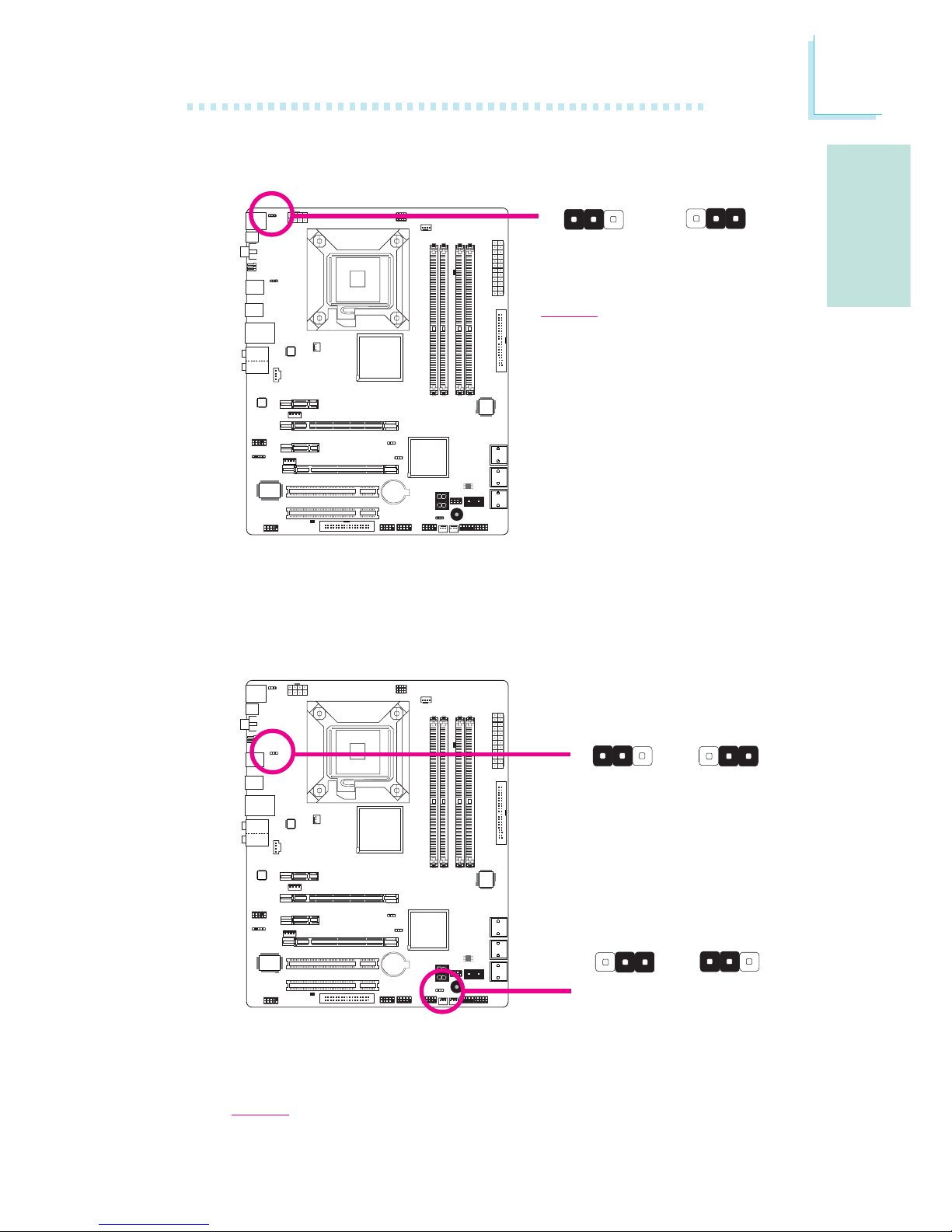
PS/2 Power Select
Die Auswahl von 5VSB erlaubt es Ihnen, Ihr System per PS/2 Keyboard oder PS/2 Maus aufzuwecken.
1-2 On: 5V
(Standard)
USB Power Select
1-2 On: 5V
(Standard)
1-2 On: 5V
(Standard)
Wichtig:
Die 5VSB Stromquelle Ihres
Netzteils muss ≥720mA unterstützen.
2-3 On:
5VSB
X
JP7
3
1231
2
2-3 On: 5VSB
2-3 On:
5VSB
X
USB 6-11
(JP5)
X
USB 0-5
(JP6)
312 312
31
2
312
Die Auswahl von 5VSB erlaubt es Ihnen, Ihr System per USB Keyboard oder USB Maus aufzuwecken.
Wichtig:
Die 5VSB Stromquelle Ihres Netzteils muss ≥1.5V (2 ports) oder ≥2V (3 oder
mehr Ports) Vunterstützen.
Page 64
Deutsch
G
64
Deutsch
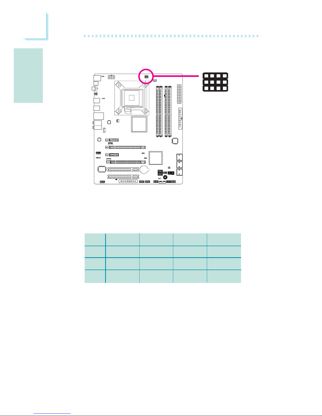
Standardmäßig sind alle drei Steckbrücken auf die Pins 1 und 2
gesetzt. Auf diese Weise läuft das System entsprechend dem
Frontside Bus der CPU. Falls Sie die Einstellungen ändern wollen,
finden Sie Informationen in der folgenden Tabelle.
JP17
JP18
JP19
CPU
1-2 On
1-2 On
1-2 On
FSB 800
2-3 On
3-4 On
2-3 On
FSB 1066
2-3 On
2-3 On
2-3 On
FSB 1333
2-3 On
2-3 On
3-4 On
CPU FSB Select
X
JP17
42
3
JP18
JP19
1
Page 65
G
Deutsch
65
Deutsch
Rückseite I/O Ports
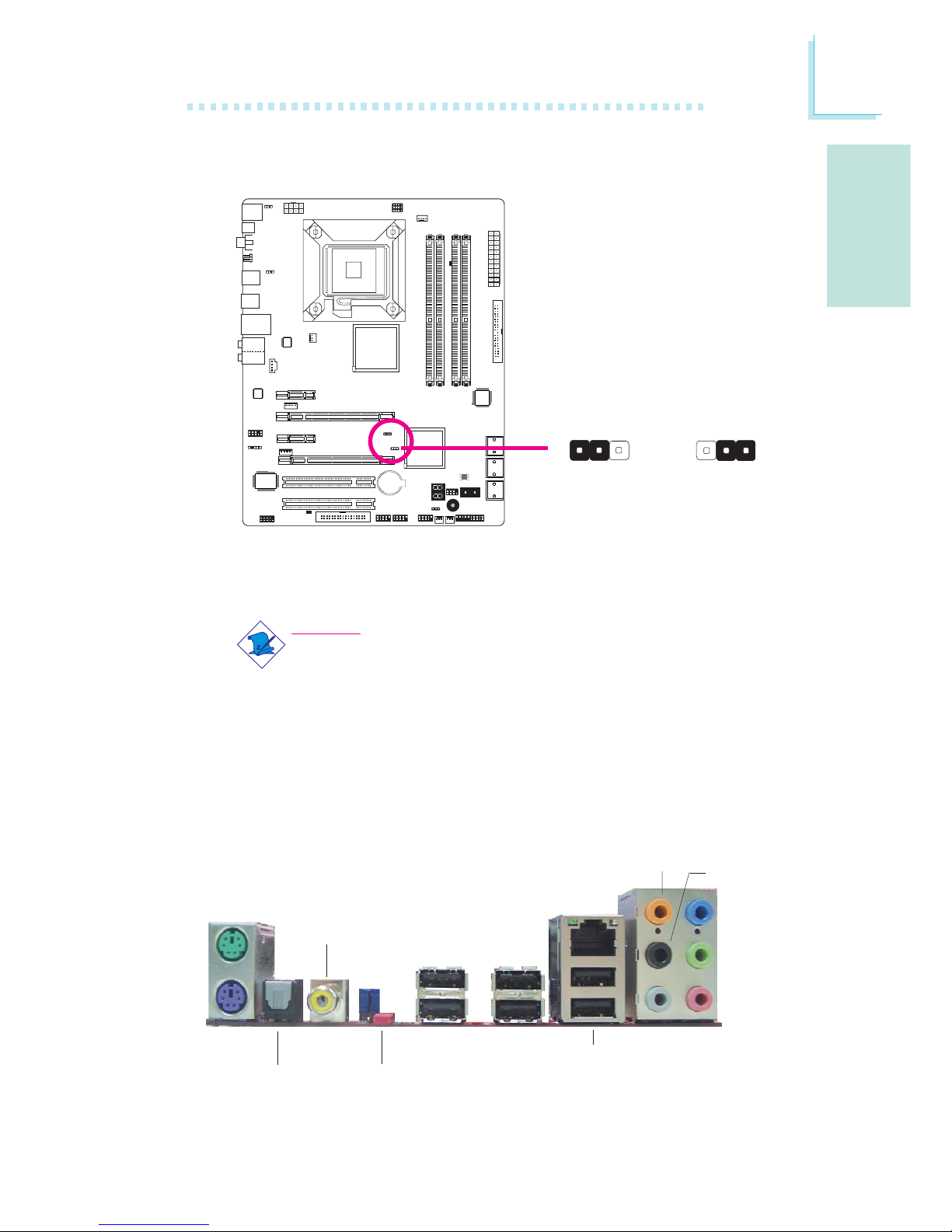
Secondary RTC Reset
Wird die RTC-Batterie entfernt, setzt diese Steckbrücke die
Handhabbarkeit der Registerbits der RTC zurück.
Hinweis:
1. Der SRTCRST# Input muss immer hoch sein, wenn alle
anderen RTC Versorgungslagen laufen.
2. In dem Fall dass die RTC-Batterie leer ist oder ganz fehlt,
muss der SRTCRST# Pin vor dem RSMRST# Pin stehen.
1-2 On: Normal
(Standardwert)
PS/2 K/B
S/PDIF
optischenAnschlüsse
USB 10-11
USB 6-7
S/PDIF coaxial RCA-
Anschlüsse
Mic-in
Side R/L
Center/
Subwoofer
Rear R/L
Line-in
Front R/L
LAN
PS/2
Mouse
USB 8-9
Clear
CMOS
jumper
2-3 On:
RTC reset
X
JP12
1
3
2
13
2
Page 66
Deutsch
G
66
Deutsch
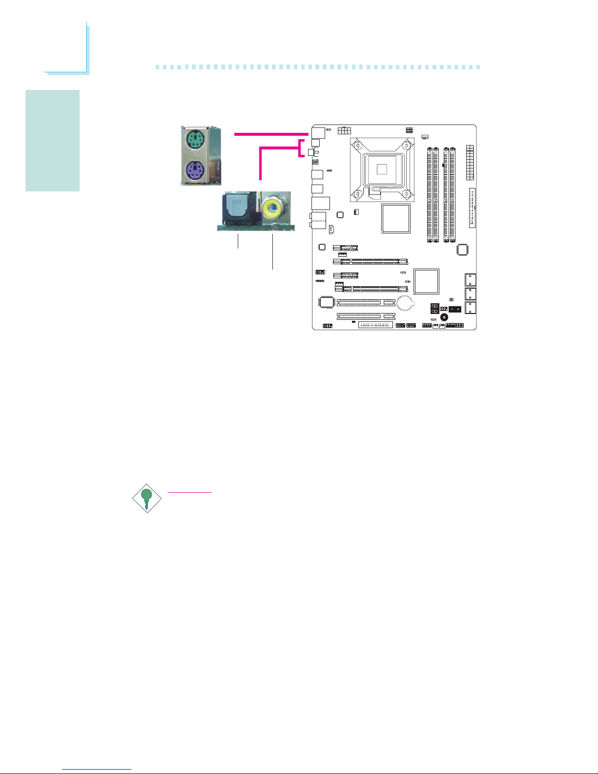
PS/2 Maus und PS/2 Keyboard Ports
Diese Ports werden zum Anschluss von PS/2 Maus und PS/2 Keyboard verwendet.
Coaxial RCA S/PDIF und Optischer S/PDIF Stecker
Mit diesen Steckern verbinden Sie externe Audioausgabegeräte die
koaxiale/Optischer S/PDIF Kabel verwenden.
Wichtig:
Verwenden Sie NICHT optische S/PDIF und koaxiale RCA S/
PDIF gleichzeitig.
PS/2 Ports und S/PDIF Ports
W
PS/2 Mouse
PS/2 KB
Optischer
S/PDIF
Coaxial RCA
S/PDIF
W
Page 67
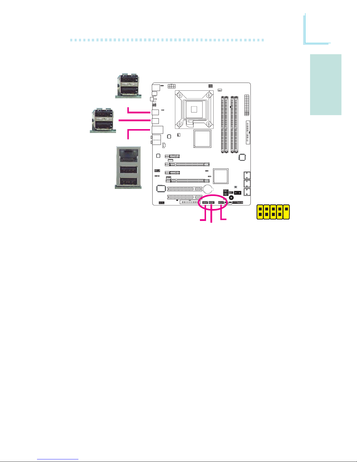
G
Deutsch
67
Deutsch
USB Ports
Über die USB Ports verbinden Sie USB 2.0/1.1 Geräte. Die 10-Pin
Anschlüsse erlauben Ihnen den Anschluss von 6 zusätzlichen USB
2.0/1.1 Ports. Ihre USB Ports könnten auf einem Halterungsblech
befestigt sein. Installieren Sie das Blech in eine verfügbare Halterung
an der Rückseite des Gehäuses und verbinden Sie das Kabel des
USB Ports mit dem entsprechenden Anschluss.
LAN Ports
Über die LAN Ports können Sie das Systemboard über einen
Netzwerk-Hub mit einem lokalen Netzwerk verbinden.
USB Ports und LAN Ports
1
VCC
-Data
+Data
GND
Key
VCC
-Data
+Data
GND
N. C.
2
10
9
W
USB 4-5
W
USB 0-1
USB 9
W
LAN
USB 8
USB 11
USB 10
USB 7
USB 6
USB 2-3
Page 68
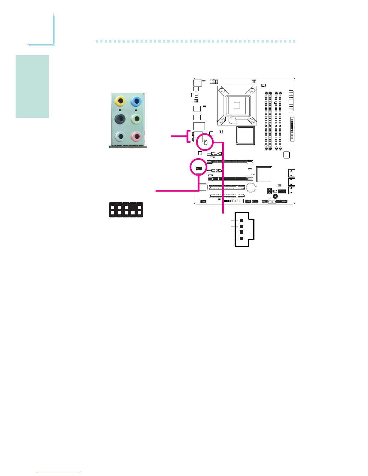
Deutsch
G
68
Deutsch
Audio und CD-In
Center/Subwoofer Stecker (Orange)
Mit diesem Stecker verbinden Sie die Center und Subwoofer
Lautsprecher Ihres Audiosystems mit dem System.
Rear Right/Left Jack (Schwarz)
Mit diesem Stecker verbinden Sie die hinten links und hinten rechts
Lautsprecher Ihres Audiosystems mit dem System.
Side Right/Left Jack (Grau)
Mit diesem Stecker verbinden Sie die seitlich links und seitlich rechts
Lautsprecher des Audiosystems mit dem System.
Line-in Stecker (Hellblau)
Mit diesem Stecker verbinden Sie beliebige Audiogeräte wie z.B.
Stereoanlagen, CD-Player, Kassettenrecorder, AM/FM Radios, Synthesizer, etc.mit dem System.
Line-out Stecker (Hellgrün)
Mit diesem Stecker verbinden Sie die vorne links und vorne rechts
Lautsprecher Ihres Audiosystems mit dem System.
W
W
Rear audio
Front audio
Front R/L
Line-in
Mic-in
Rear R/L
Center/
Subwoofer
Side R/L
1
2
10
Mic-L
Mic-R
Line-out-R
Front-sense
Line-out-L
GND
Presense-signal
Mic-jack-sense
Key
Line-out-jack-sense
9
4
1
Left audio channel
Right audio channel
Ground
Ground
W
CD-in
Page 69
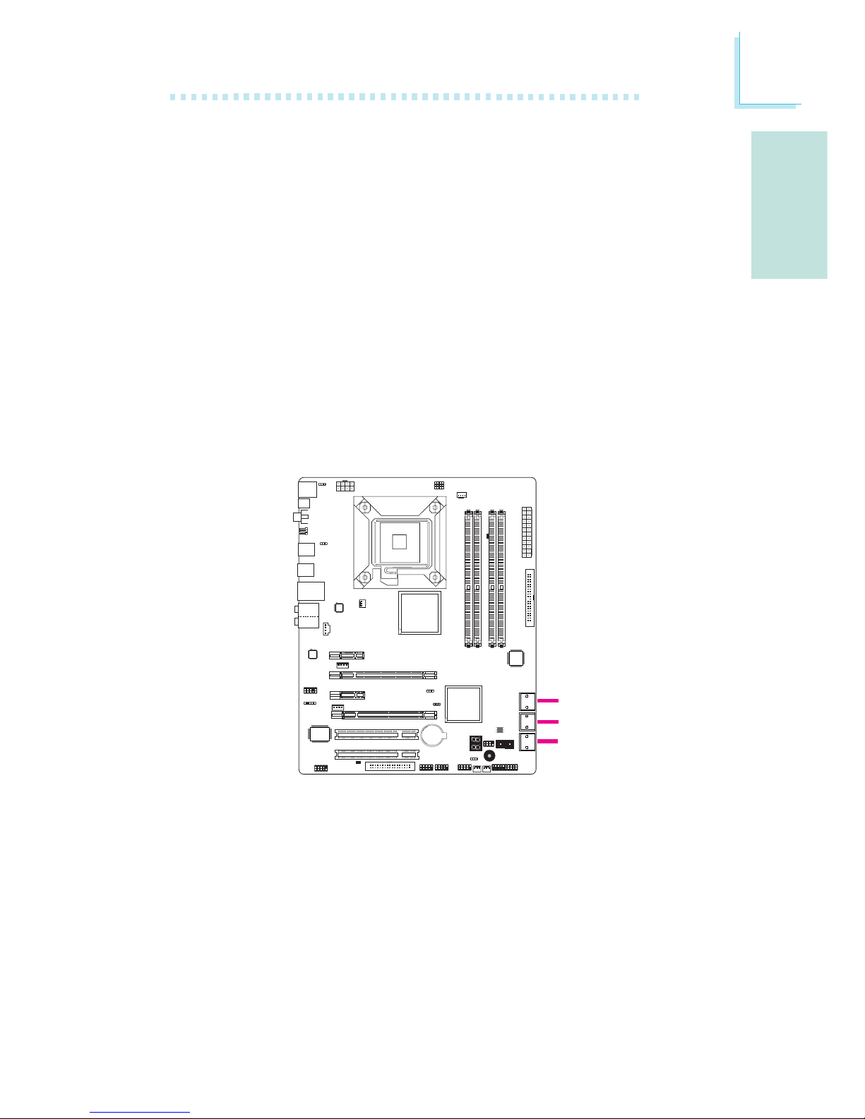
G
Deutsch
69
Deutsch
Serial ATA Anschlüsse
Über die Serial ATA (SATA) Anschlüsse werden Serial ATA
Laufwerke angeschlossen. Verbinden Sie das eine Ende des Serial ATA
Kabels mit dem Serial ATA Anschluss und das andere Ende mit
Ihrem Serial ATA Gerät.
RAID-Konfiguration
Bitte lessen Sie im Kapitel RAID dieses Handbuchs, um weitere
Informationen zur Erzeugung von RAID auf Serial ATA Laufwerken zu
erhalten.
I/O Anschlüsse
Mic-in Stecker (Pink)
Mit diesem Stecker verbinden Sie ein externes Mikrophon mit dem
System.
Front Audio Anschluss
Mit dem Front Audio Anschluss werden die line-out und mic-in
Stecker die sich an der Frontseite des Gehäuses befinden verbunden.
CD-in Anschluss
Der CD-in Anschluss wird verwendet, um Audio von einem CDROM Laufwerk, einer TV Tuner oder MPEG-Karte zu empfangen.
SATA 2-3
SATA 0-1
SATA 4-5
Page 70
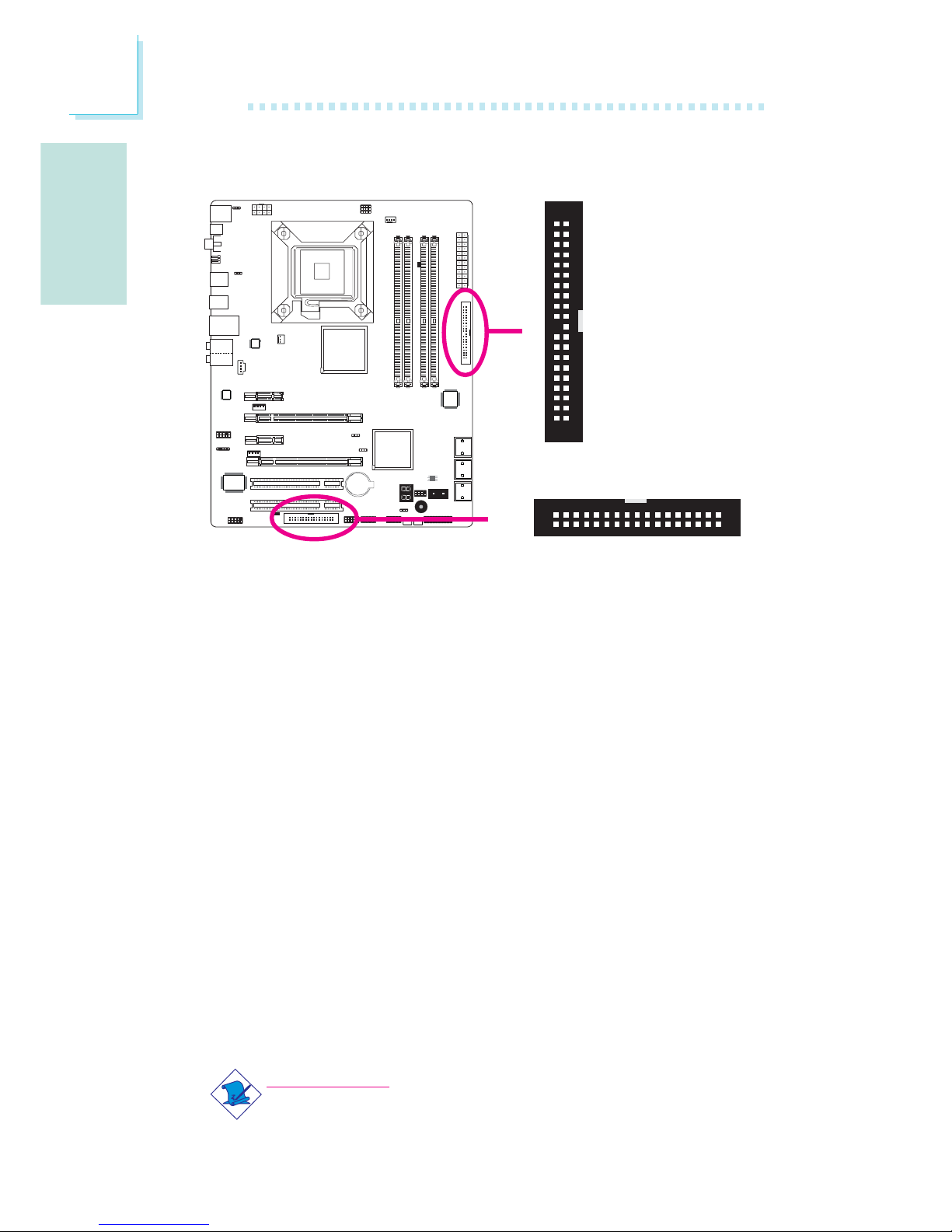
Deutsch
G
70
Deutsch
Floppy Disk Drive Anschluss
Über den Floppy Disk Drive Anschluss werden Floppy-Laufwerke
angeschlossen. Er verfügt über einen Verbindungsmechanismus der
eine Fehlinstallation vermeidet. Verbinden Sie ein Ende des FloppyKabels mit dem Anschluss auf dem Board und das andere Ende mit
dem Floppy-Laufwerk. Das farblich markierte Ende des Kabels muss
mit Pin 1 des Anschlusses in Übereinstimmung gebracht werden.
IDE Disk Drive Anschluss
Über den IDE Disk Drive Anschluss werden 2 IDE Laufwerke
angeschlossen. Er verfügt über einen Verbindungsmechanismus der
eine Fehlinstallation vermeidet. Das IDE-Kabel hat 3
Steckverbindungen, eine für den IDE Disk Drive Anschluss und die
anderen beiden für die IDE-Laufwerke. Der Stecker am Ende des
Kabels ist für das Master-Laufwerk und der in der Mitte des Kabels
ist für das Slave-Laufwerk vorgsehen. Das farblich merkierte Ende
des Kabels muss mit Pin 1des Anschlusses in Übereinstimmung
gebracht werden.
Bitte beachten:
Wenn Sie 2 IDE-Laufwerke verwenden muss eins als Master
und eins als Slave eingestellt sein. Folgen Sie den Anweisungen
des Herstellers der Laufwerke bezüglich der Einstellungen der
Jumper und/oder Schalter.
Floppy Disk Drive Anschluss und IDE Anschluss
X
40
39
21
X
IDE
FDD
34
33
1
2
Page 71
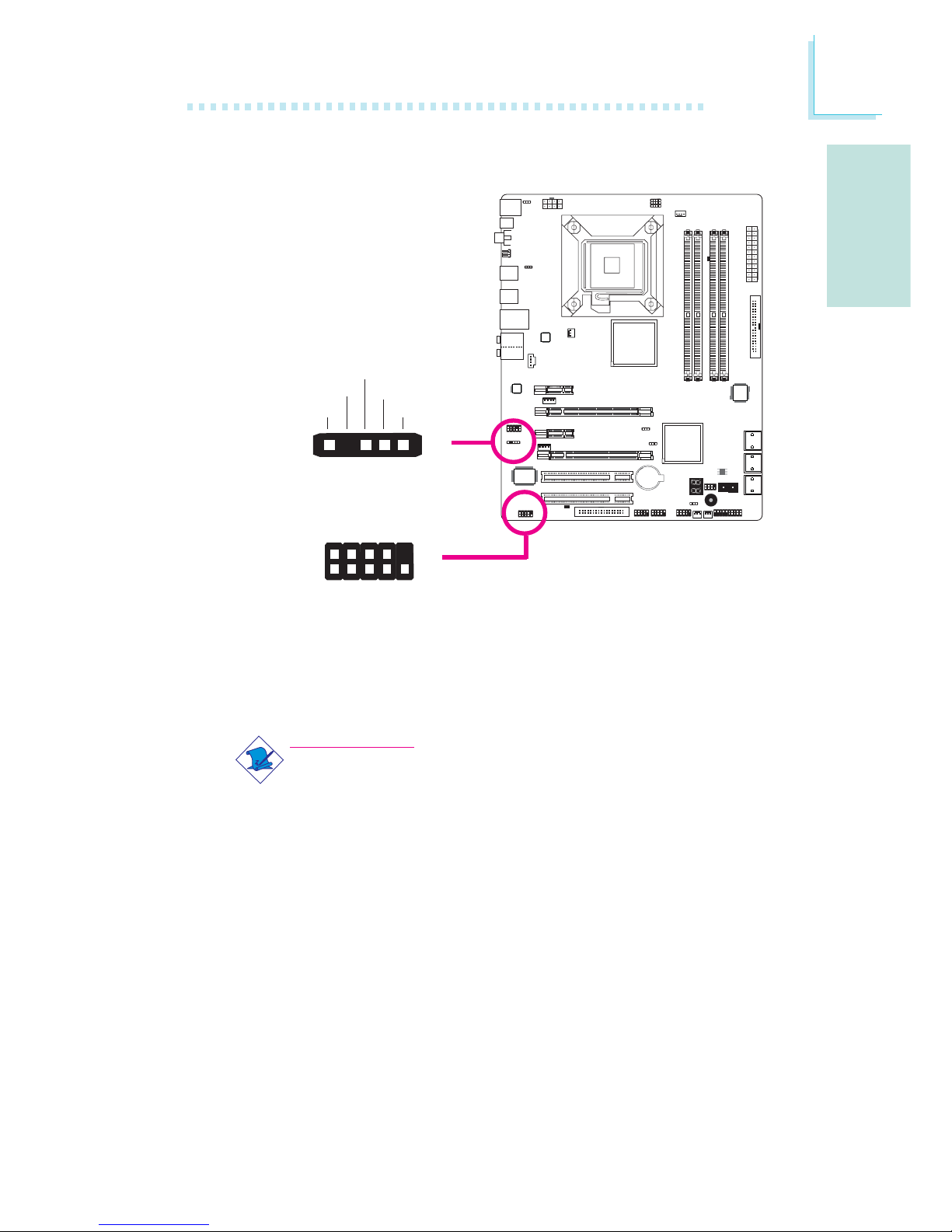
G
Deutsch
71
Deutsch
IrDA und Serial (COM) Anschlüsse
IrDA Anschlüsse
Dieser Anschluss unterstützt ein Infrarotmodul.
Bitte beachten:
Die Anordnung der PIN-Funktionen kann bei einigen IrDA
Kabeln abweichend von der Anordnung auf dem Systemboard
sein. Bitte stellen Sie sicher, dass die Pinbelegungen des Kabels
und des IrDA Anschlusses auf dem Systemboard miteinander
übereinstimmen.
Um die IrDA Funktion nutzen zu können könnte es notwendig sein,
die entsprechenden Treiber in Ihrem Betriebssystem zu installieren.
Informationen hierzu erhalten Sie aus dem Benutzerhandbuch des
Betriebssystems.
Serial (COM) Anschluss
Mit dem Serial (COM) Anschluss verbinden Sie Modems, serielle
Drucker, Display Terminals oder andere serielle Geräte mit dem System. Ihr COM Anschluss könnte auf einem Halterungsblech befestigt
sein. Installieren Sie das Blech in eine verfügbare Halterung an der
W
1
9
2
CD
TD
RD
DTR
GND
RTS
DSR
CTS
RI
COM
15
VCC
N. C.
IRRX
Ground
IRTX
IrDA
X
Page 72
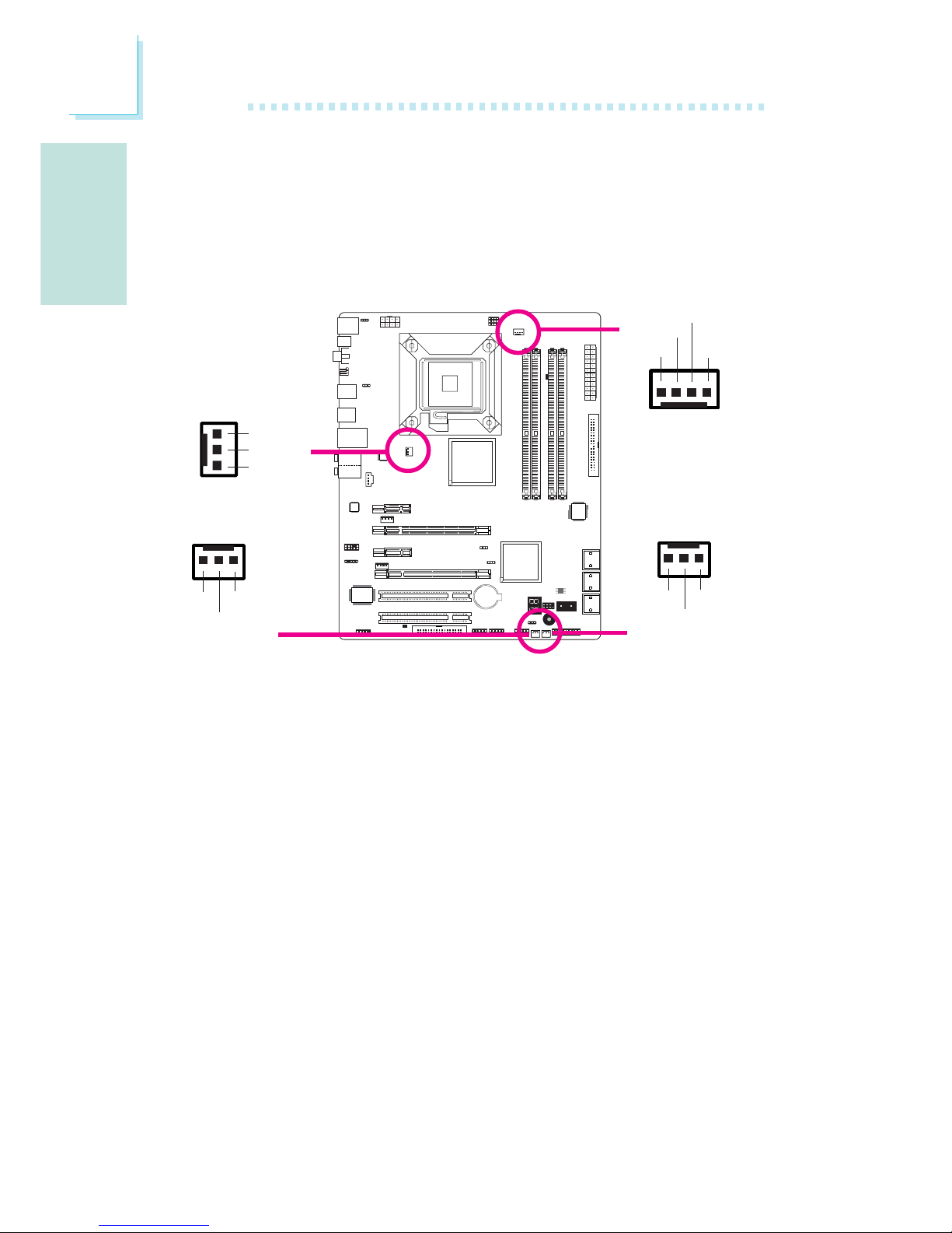
Deutsch
G
72
Deutsch
Lüfteranschlüsse
Über diese Lüfteranschlüsse werden Lüfter mit dem System
verbunden. Diese Lüfter sorgen für ausreichende Luftzirkulation im
Gehäuse und verhindern somit ein Überhitzen der CPU und der
Komponenten auf dem Systemboard.
Rückseite des Gehäuses und verbinden Sie das Kabel des seriellen
Ports mit dem entsprechenden Anschluss. Das farblich markierte
Ende des Kabels muss mit Pin 1 des Anschlusses in
Übereinstimmung gebracht werden.
X
X
CPU fan
Chassis fan
System fan
X
NB fan
1
3
Sense
Power
On/Off
4
1
Sense
Power
Ground
Speed
Control
3
1
Ground
Power
Sense
X
3
1
Ground
Power
Sense
Page 73
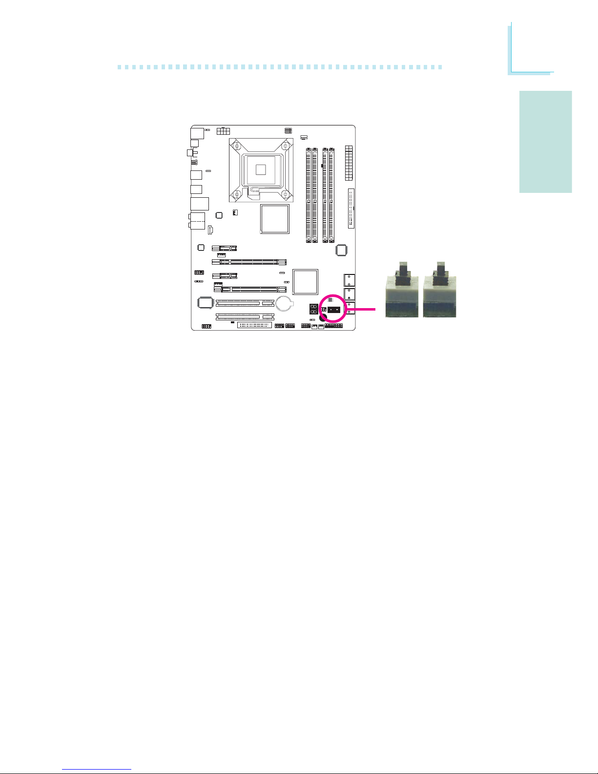
G
Deutsch
73
Deutsch
EZ Touch Schalter
Das Vorhandensein von Power- und Reset-Schaltern auf dem
Systemboard ist speziell für DIY-User sehr anwenderfreundlich. Sie
bieten die Möglichkeit bequem das System ein-/auszuschalten und
einen Reset durchzuführen und somit die Einstellungen des
Systemboards zu verfeinern bevor es in ein Gehäuse eingebaut wird.
X
Reset Power
Page 74
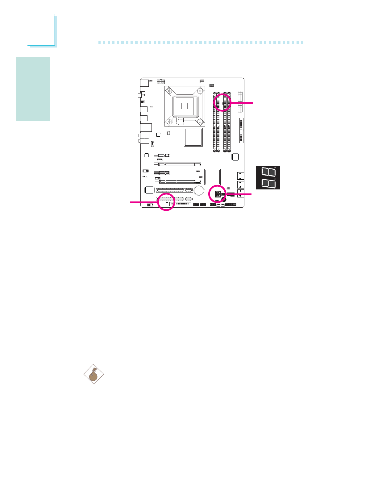
Deutsch
G
74
Deutsch
LEDs
DRAM Power LED
Diese LED leuchtet wenn das System eingeschaltet ist.
Standby Power LED
Diese LED leuchtet wenn das System im Standby Modus ist.
Diagnostic LED
Die Diagnostic LED zeigt POST Codes an. POST (Power-On Self
Tests), die durch das BIOS gesteuert werden, werden bei jedem
Start des Systems durchgeführt. Der POST erkennt den Status des
Systems und seiner Komponenten. Jeder durch die LED angezeigte
Code entspricht einem bestimmten Systemstatus.
Warnung:
Eine aufleuchtende DRAM Power LED und/oder Standby Power
LED zeigt an, dass die DIMM-Sockel und/oder PCI-Steckplätze
unter Spannung stehen. Schalten Sie den PC aus und ziehen Sie
den Netzstecker bevor Sie Speichermodule oder Zusatzkarten
installieren. Bei Nichtbeachtung drohen erhebliche Schäden am
Motherboard und den Komponenten.
.
.
.
.
.
.
.
.
DRAM
Power LED
Standby
Power LED
Diagnostic
LED
Page 75
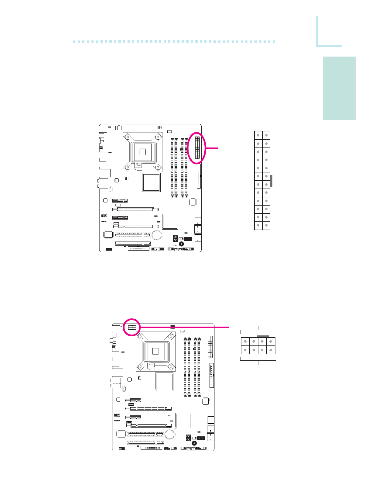
G
Deutsch
75
Deutsch
Stromanschlüsse
Verwenden Sie ein Netzteil, dass den ATX12V Netzteil
Designrichtlinien Version 1.1 entspricht. Ein ATX12V Netzteil verfügt
über einen standard 24-Pin ATX Hauptstromanschluss. Verbinden Sie
diese Stromanschlüsse.
Ihr Netzteil könnte über einen 8-Pin oder 4-Pin +12V Anschluss
verfügen. Der +12V Anschluss erlaubt die Bereitstellung von mehr
+12VDC Spannung für das Voltage Regulator Module (VRM) des
Prozessors. Falls verfügbar sollten Sie bevorzugt den 8-Pin Anschluss
verwenden, falls nicht vorhanden den 4-Pin Anschluss.
X
131
12 24
+3.3VDC
+3.3VDC
COM
+5VDC
COM
+5VDC
COM
PWR_OK
+5VSB
+12VDC
+12VDC
+3.3VDC
+3.3VDC
-12VDC
COM
PS_ON#
COM
COM
COM
NC
+5VDC
+5VDC
+5VDC
COM
X
+12V
Ground
14
58
Page 76
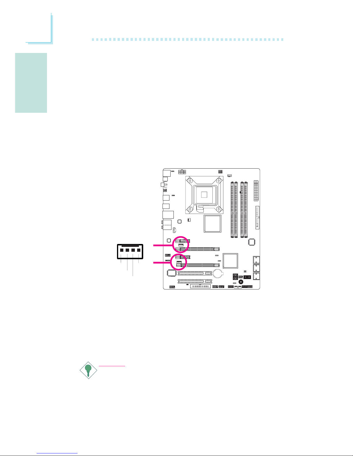
Deutsch
G
76
Deutsch
Das Systemboard benötigt zum Betrieb ein Netzteil mit mindestens
300 Watt. Ihre Systemkonfiguration (CPU Power, Grösse des
Speichers, Zusatzkarten, Perpheriegeräte, etc.) können den
Strombedarf des Systems zusätzlich erhöhen. Um sicher zu stellen,
dass ausreichende Stromversorgung zur Verfügung steht empfehlen
wir, ein Netzteil mit mindestens 400 Watt oder mehr zu verwenden.
Wichtig:
Ungenügende Stromversorgung kann zu Instabilität führen oder
fehlerhafte Funktion von Zusatzkarten und Peripheriegeräten
zur Folge haben. Die Berechnung des Stromverbrauchs des Systems ist wichtig, um sicherzustellen, dass das eingesetzte
Netzteil den Anforderungen des Systems entspricht.
Die Stromanschlüsse des Netzteils sind so entworfen, dass die die
24-Pin und 8-Pin Anschlüsse nur in einer Ausrichtung verbunden
werden können. Stellen Sie sicher, dass die Ausrichtung korrekt ist
bevor Sie die Anschlüsse verbinden.
Die FDD-Typ Stromanschlüsse sind zusätzliche Stromanschlüsse.
Sollten Sie mehr als eine Grafikkarte verwenden, so empfehlen wir,
dass Sie die Stromkabel des Netzteils mit den 5V/12V
Stromanschlüssen verbinden. Dies wird das komplette System mit
mehr Stabilität versorgen. Das Systemboard wird nach wie vor
arbeiten, auch wenn die zusätzlichen Stromanschlüsse nicht
angeschlossen sind.
1
4
+5V
+12V
Ground
Ground
Page 77

G
Deutsch
77
Deutsch
Neustart des PC’s
In der Regel lässt sich der PC wie folgt ausschalten:
1. Betätigung des Power-Schalters auf der Frontseite des Gehäuses.
oder
2. Betätigung des Power-Schalters der sich auf dem Systemboard
befindet (Anmerkung: nicht alle Systemboards verfügen über
diesen Schalter).
Sollten Sie jedoch die Stromzufuhr zu Ihrem PC komplett
unterbrechen wollen, so schalten Sie das Netzteil aus oder ziehen Sie
den Netzstecker. Wenn Sie den PC sofort neustarten wollen sollten
Sie unbedingt die folgenden Schritte befolgen.
1. Die Dauer in der sich der Strom komplett entlädt ist von Netzteil
zu Netzteil unterschiedlich. Diese Länge der Zeitspanne hängt
dabei stark von der Systemkonfiguration wie z.B. der Wattzahl des
Netzteils, der Anordnung des Netzteils oder der Anzahl der an
das System angeschlossenen Peripheriegeräte ab. Aus diesem
Grund empfehlen wir, auf das Auflleuchten der Standby Power
LED (siehe dazu auch den Abschnitt “LED’s” in diesem Kapitel) zu
warten.
2. Warten Sie mit dem Einschalten des PC’s bis die Power LED
etwa 6 Sekunden erloschen ist.
Sollte das Systemboard bereits in ein Gehäuse eingebaut sein und
die Standby Power LED dadurch nicht sichtbar sein, so warten
Sie bitte 15 Sekunden bevor Sie die Stromzufuhr wieder
herstellen. Es dauert etwa 15 Sekunden bis die LED erlischt und
dies ist auch die Zeitspanne, die vor einem Neustart notwendig
ist.
Die o.g. Regeln stellen einen Schutz vor Beschädigung des
Motherboards und der Komponenten dar.
Page 78
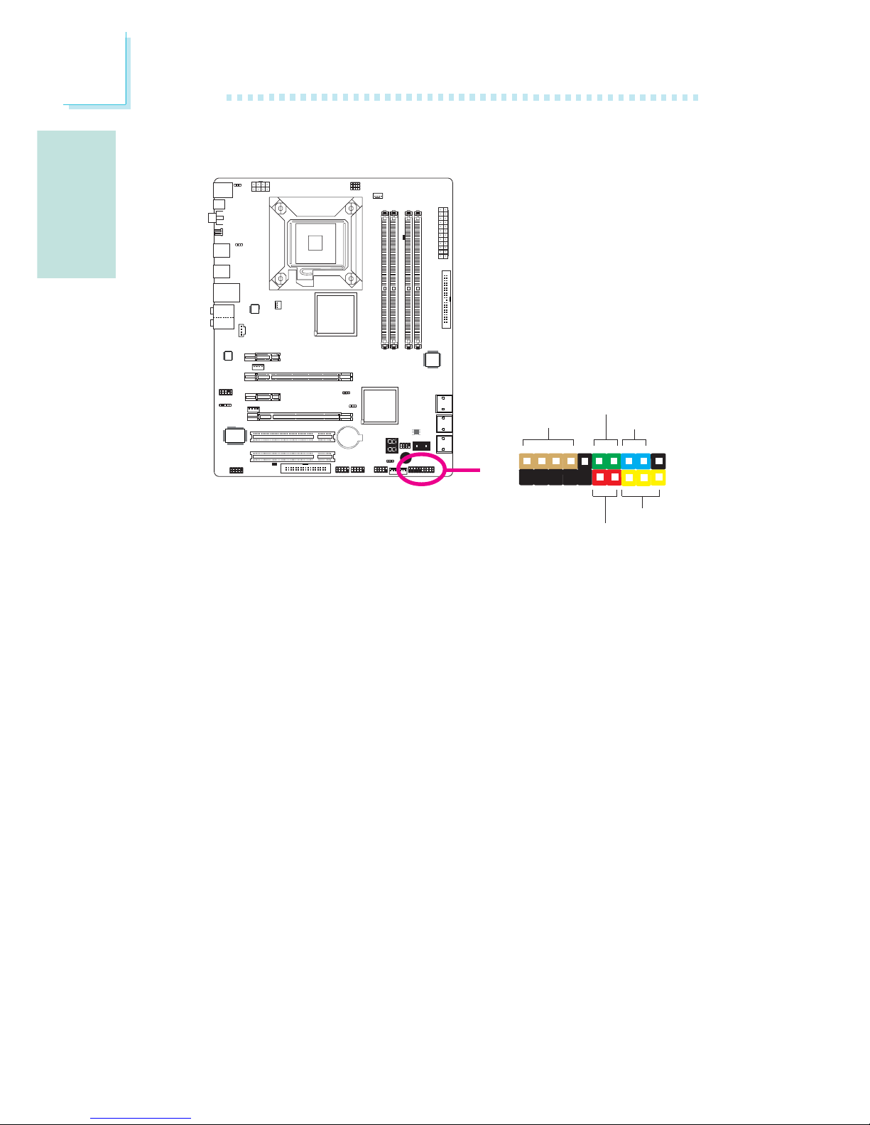
Deutsch
G
78
Deutsch
Frontanschlüsse
HD-LED: Primäre/Sekundäre IDE LED
Diese LED leuchtet auf, wenn auf die Festplatte zugegriffen wird.
RESET: Reset-Schalter
Dieser Schalter erlaubt es Ihnen einen Neustart durchzuführen ohne
die Stromzufuhr zu unterbrechen. Dadurch wird die Lebensdauer des
Netzteils und des Systems verlängert.
SPEAKER: Lautsprecheranschluss
Dieser stellt die Verbindung zu dem im System installierten
Lautsprecher her.
ATX-SW: ATX Power-Schalter
Abhängig von den Einstellungen im BIOS Setup ist dieser Schalter ein
“dual function power button” der es erlaubt Ihr System in den SoftOff oder Suspend Modus zu versetzen.
X
1
2
19
20
HD-LED
RESET
SPEAKER
PWR-LED
ATX-SW
Page 79
G
Deutsch
79
Deutsch
PWR-LED: Power/Standby LED
Diese LED leuchtet, wenn die Stromzufuhr des Systems eingeschaltet
ist. Sollte das System sich im S1 (POS - Power On Suspend) oder
S3 (STR - Suspend To RAM) Status befinden, so blinkt die LED
einmal pro Sekunde.
Bitte beachten:
Sollte das System nicht hochfahren und die Power/Standby LED
nicht aufleuchten nachdem Sie den Power-Schalter betätigt
haben, so könnte dies darauf hinweisen, dass die CPU oder die
Speichermodule nicht korrekt installiert wurden. Bitte stellen Sie
sicher, dass diese ordnungsgemäss in ihren entsprechenden
Steckplätzen eingesetzt sind.
Pin
3
5
14
16
8
10
18
20
7
9
13
15
17
19
2
4
6
HD-LED
(Primary/Secondary IDE LED)
Reserved
ATX-SW
(ATX power switch)
Reserved
RESET
(Reset switch)
SPEAKER
(Speaker connector)
PWR-LED
(Power/Standby LED)
Pin Assignment
HDD LED Power
HDD
N. C.
N. C.
PWRBT+
PWRBT-
N. C.
N. C.
Ground
H/W Reset
Speaker Data
N. C.
Ground
Speaker Power
LED Power (+)
LED Power (+)
LED Power (-) or Standby Signal
Page 80
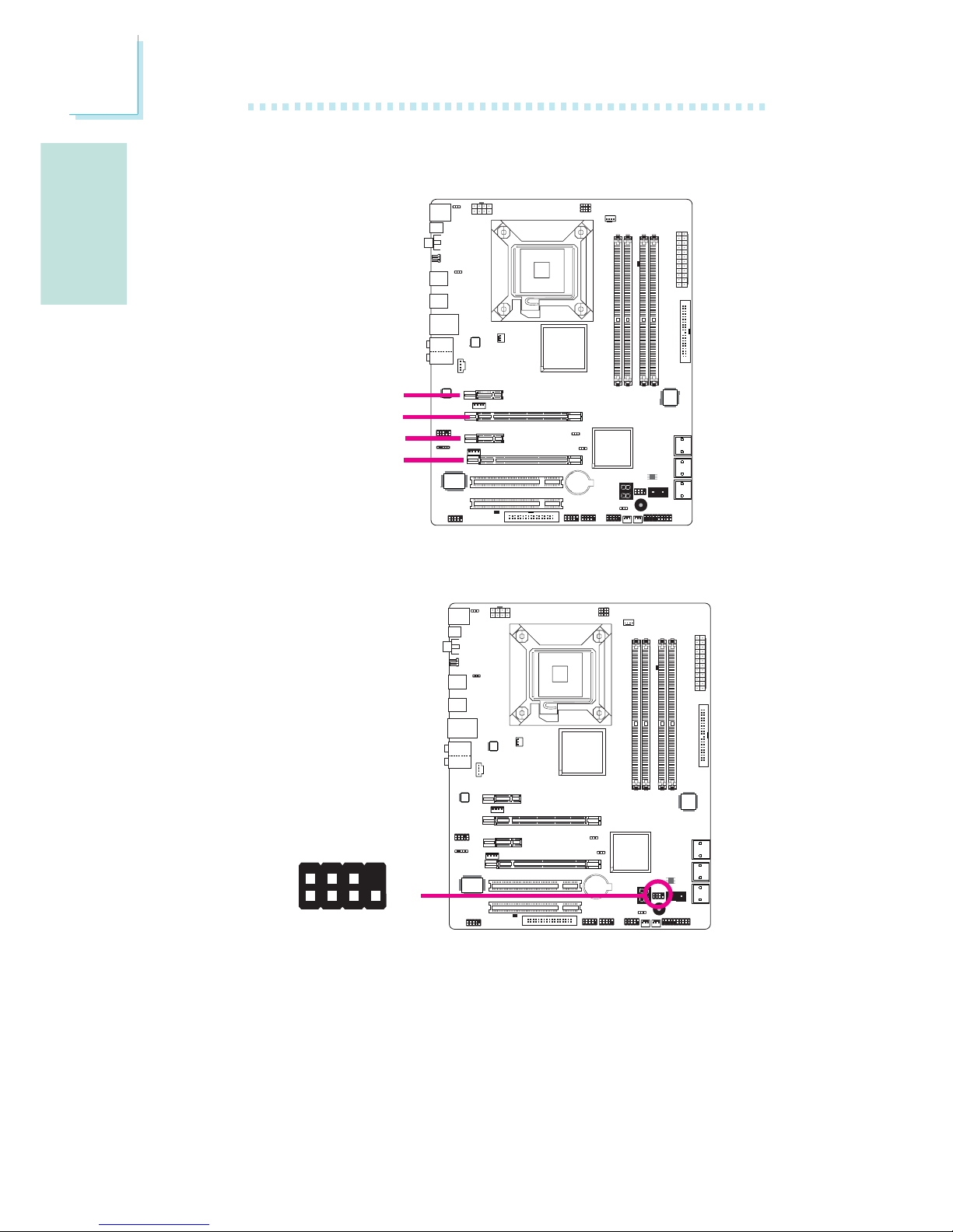
Deutsch
G
80
Deutsch
PCI Express Steckplätze
Download Flash BIOS Anschlüsse
W
1
GROUND
2
8
7
SPI_VCC3
SPI_CS0B
SPI_MIS0
SPI_HOLD#
SPI_CLK
SPI_MOSI
PCI Express x1
PCI Express x16
PCI Express x16
PCI Express x1
Page 81

G
Deutsch
81
Deutsch
Der ICH10R Chip erlaubt es RAID auf Serial ATA Festplatten zu
konfigurieren. Er unterstützt RAID 0, RAID 1, RAID 0+1 und RAID
5.
RAID Level
RAID 0 (Festplattenanordnung in Datenstreifen ohne
Fehlertoleranz)
RAID 0 verwendet zwei neue identische Festplatten zum parallelen,
in überlappenden Blöcken liegenden Lesen und Schreiben von Daten.
Die Daten werden in Streifen aufgeteilt und jeder Streifen wird
alternativ auf die Festplatten geschrieben. Dies erhöht die I/O Performance der Festplatten, bietet jedoch keine Fehlertoleranz. Eine
fehlerhafte Festplatte kann in diesem RAID zu Datenverlust führen.
RAID 1 (Gespiegelte Festplattenanordnung mit Fehlertoleranz)
RAID 1 kopiert und behält eine identische Spiegelung der Daten
von einem Laufwerk zum anderen bei. Sollte eines der Laufwerke
ausfallen, so leitet die Management Software der
Festplattenanordnung alle Applikationen auf das andere Laufwerk um,
da dort die gleichen Daten gespiegelt vorhanden sind. Dies erhöht
den Schutz Ihrer Daten und erhöht die Fehlertoleranz des
kompletten Systems. Verwenden Sie hierfür zwei neue Laufwerke
oder ein bereits vorhandes und ein neues aber beachten Sie, dass
das neue Laufwerk die gleiche oder eine grössere Kapazität als das
bereits vorhandene aufweisen muss.
RAID 0+1 (Datenstreifen und Spiegelung)
RAID 0+1 ist eine Kombination der Speicherung der Daten in
Streifen und als Spiegelung und bietet somit die Vorteile sowohl von
RAID 0 als auch von RAID 1. Verwenden Sie für diese Konfiguration
vier neue Laufwerke oder ein bereits vorhandenes und drei neue
Laufwerke.
Kapitel 3 - RAID
Page 82

Deutsch
G
82
Deutsch
RAID 5
RAID 5 führt Striping von sowohl Daten- als auch
Paritätsinformationen über Festplatten aus. Zu seinen Vorteilen zählen
Fehlertoleranz, eine bessere Festplattenleistung und höhere
Speicherkapazität.
Einstellungen
Um die RAID-Funktion zu aktivieren sind folgende Einstellungen
notwendig.
1. Schliessen Sie die Serial ATA Laufwerke an.
2. Konfigurieren Sie Serial ATA im Award BIOS.
3. Konfigurieren Sie RAID im RAID BIOS.
4. Installieren Sie den RAID-Treiber während der Installation des
Betriebssystems.
5. Installation des Intel Matrix Storage Manager
Schritt 1: Schliessen Sie die Serial ATA Laufwerke an
Informationen zum Anschluss der Serial ATA Laufwerke finden Sie in
Abschnitt 2.
Wichtig:
1. Stellen Sie sicher, dass die Serial ATA Laufwerke installiert und dass die
Datenkabel korrekt angeschlossen sind. Ansonsten ist es nicht möglich, das
RAID BIOS Utility Programm zu verwenden.
2. Behandeln Sie die Kabel sehr vorsichtig, besonders beim Einrichten von RAID.
Beschädigte Kabel können den kompletten Installationsprozess zunichte
machen und das Betriebssystem beschädigen. Das System wird nicht
hochfahren und Sie werden alle Daten auf den Festplatten verlieren. Bitte
beachten Sie unbedingt diese Warnung, verlorengegangene Daten können
nicht wieder hergestellt werden!
Schritt 2: Konfiguration von Serial ATA im Award BIOS
1. Schalten Sie das System ein und drücken Sie dann die <Del>
Taste, um in das Hauptmenü des Award BIOS zu gelangen.
2. Wählen Sie das Integrated Peripherals Untermenü – Abschnitt
OnChip IDE Device des BIOS aus.
3. Konfigurieren Sie Serial ATA in den entsprechenden Feldern.
4. Drücken Sie die <Esc> Taste um ins Hauptmenü des BIOS Setup
zu gelangen. Wählen Sie “Save & Exit Setup” aus und drücken Sie
dann die <Enter> Taste.
Page 83

G
Deutsch
83
Deutsch
5. Schreiben Sie <Y> und drücken dann die <Enter> Taste.
6. Führen Sie einen Neustart des Systems durch.
Step 3: Konfiguration von RAID im RAID BIOS
Wenn das System hochfährt und alle Laufwerke erkannt wurden
erscheint die RAID BIOS Status Nachricht auf dem Bildschirm.
Drücken Sie die <Ctrl>+<I> Taste um das Programm aufzurufen.
Das Programm ermöglicht es Ihnen ein RAID system auf den Serial
ATA Laufwerken einzurichten.
Schritt 4: Installation des RAID Treibers während der Installation des
Betriebssystems.
Der RAID Treiber muss während der Installation von Windows® XP
oder Windows® 2000 per F6 Installationsmethode eingerichtet
werden. Dies ist notwendig um das Betriebssystem auf eine
Festplatte oder RAID System zu installieren die im RAID-Modus sind
oder auf eine Festplatte wenn sie im AHCI-Modus ist.
1. Starten Sie das Windows Setup indem Sie von der Installations-
CD booten.
2. Drücken Sie die <F6> Taste, wenn die Nachricht ‘Press F6 if you
need to install a third party SCSI or RAID driver’ auf dem
Bildschirm erscheint.
3. Wählen Sie <S> für “Specify Additional Device” aus.
4. Nun werden Sie aufgefordert eine Diskette die den RAID Treiber
enthält einzulegen. Legen Sie die mitgelieferte RAID Treiberdiskette
ein.
5. Wählen Sie das Laufwerk aus in das Sie die Diskette eingelegt
hatten und wählen Sie anschliessend den RAID oder AHCI Controller der mit Ihrem BIOS Setup übereinstimmt. Drücken Sie die
<Enter> Taste zur Bestätigung.
Sie haben nun den Treiber erfolgreich installiert. Sie müssen aber
dennoch mit der Installation des Betriebssystems fortfahren. Belassen
Sie die Diskette im Floppy-Laufwerk bis das System automatisch
neustartet. Das Windows Setup muss noch erneut die Dateien von
der Diskette in die Windows Installationsordner kopieren. Nachdem
das Windows Setup die Dateien kopiert hat können Sie die Diskette
entfernen, so dass das Windows Setup wie erforderlich neustarten
kann.
Page 84

Deutsch
G
84
Deutsch
Schritt 5: Installation des Intel Matrix Storage Manager
Der Intel Matrix Storage Manager kann innerhalb von Windows
installiert werden. Er erlaubt RAID-Volumen-Management (erstellen,
löschen, migrieren) innerhalb eines Betriebssystems. Zudem werden
nützliche Informationen über SATA Geräte und RAID Volumen
angezeigt. Benutzeroberfläche, Tray-Symbol-Service und Monitorservice
ermöglichen das Beobachten des aktuellen Status des RAIDVolumens und/oder der SATA Laufwerke. Er ermöglicht eine bessere
Leistung und ein Power Management für das Speicher-Subsystem.
1. Legen Sie die CD in das CD-ROM-Laufwerk.
2. Klicken Sie auf der linken Seite des Autorun-Bildschirms auf das
„CHIPSET” Symbol.
3. Klicken Sie im Hauptmenü auf „Intel(R) Matrix Storage Manager”.
4. Folgen Sie den Hinweisen auf dem Bildschirm; klicken Sie am
Ende eines jeden Schritts auf „Weiter”.
Page 85
S
Español
85
Español
Chapter 1 - Especificaciones
Procesador
Chipset
Memoria de Sistema
Ranuras de
Expansión
BIOS
Audio
LAN
IDE
Dispositivo de
Almacenaje
• LGA 775 Zócalo de la CPU para:
- Intel® CoreTM2 Quad y Intel® CoreTM2 Duo
• Intel Realzaron Tecnología De la Memoria 64 (EMT64T)
• Realzaron La Tecnología De Intel SpeedStep (EIST)
• Intel Hiperactivo-Que rosca Tecnología (Intel Hyper-Threading)
• 1333/1066/800MHz FSB
• Intel
®
chipset
- Puente norte:
Intel® P45 Express chipset
Tecnología rápida del acceso de memoria de Intel
®
- Puente sur: Intel® ICH10R
• 4 240-pin mortajas DDR2 DIMM
• Los módulos DIMM 667/800 MHz
• Hasta 12.8GB/s de ancho de banda
• Memoria de dos canales (128-bit)
• Hasta 8GB de memoria sistémica
• Sólo unbuffered x8 y x16 DIMM
• 2 ranuras PCI Express (Gen 2) x 16 (PCIE 2 y PCIE 4)
- CrossFire de dos vías a ancho de banda de x8 (PCIE 2) +
x8 (PCIE 4)
- 1 placa de gráficos: x16 (PCIE 2/PCIE 4)
• 2 slot PCI Express x1
• 2 slots PCI
• Award BIOS
• 8Mbit SPI flash BIOS
• CMOS Reloaded
• Codificador de audio de alta definición de 8 canales Realtek
ALC885
• DAC SNR/ADC SNR de 106dB/101dB
• Tecnología protección de la contenta lossless de exploración
completa
• Interfáz de S/PDIF óptico y S/PDIF coaxial RCA
• Marvell 88E8053 PCIE Gigabit LAN
• Completamente a IEEE 802.3 (10BASE-T), 802.3u (100BASETX) y 802.3ab (1000BASE-T) estándar
• JMicron JMB368 PCI expreso al regulador del anfitrión de
PATA
• Apoya hasta 2 dispositivos del UltraDMA 33/66/100Mbps
IDE
• Intel Matrix Storage technology
• 6 puertos de Serial ATA
• Velocidad SATA de hasta 3Gb/s
• RAID 0, RAID 1, RAID 0+1 y RAID 5
Page 86
Español
S
86
Español
Panel Trasero I/O
Conectador Interno
Gerencia de la
Energía
Monitor del
Hardware
PCB
• 1 puerto de ratón mini-DIN-6 PS/2
• 1 puerto de teclado mini-DIN-6 PS/2
• 1 puerto de S/PDIF óptica
• 1 puerto de S/PDIF coaxial RCA
• 6 puertos de USB 2.0/1.1
• 1 puerto de RJ45 LAN
• Center/subwoofer, rear R/L y side R/L enchufes de audio
• Line-in, line-out (front R/L) y mic-in enchufes de audio
• 3 conectors para 6 puertos de USB 2.0 externo adicional
• 1 conector para un puerto de DB-9 serie externa
• 1 connector de sonido delantera
• 1 conector de CD-in audio interno
• 1 conector de IrDA
• 6 conectores de Serial ATA
• 1 conector de IDE
• 1 conector de FDD
• 1 conectore de 24-pin fuente de alimentación de ATX
• 1 conectore de 8-pin 12V fuente de alimentación de ATX
• 2 4-fichas conectadores de energía de 5V/12V (FDD-tipo)
• 1 conector de panel delante
• 4 conectores de abanicos
• 1 conectore de download flash BIOS
• 1 indicadore diagnósticos
• EZ conmutadores (conmutadores de alimentación y reset)
• ACPI y OS Directed Power Management
• ACPI STR (Suspend to RAM) función
• PS/2 Teclado/Ratón de Wake-On
• USB Teclado/Ratón de Wake-On
• Wake-On-Ring
• Wake-On-LAN
• Temporizador de RTC para encender el sistema
• Recuperación de Fracaso de Energía AC
• Monitores de los CPU/sistema/Puente norte temperaturas y
alarma acalorada.
• Monitores de voltajes de Vcore/Vdimm/Vnb/VCC5/12V/V5sb/
Vbat
• Vigila la velocidad del abanico del abanido
• Protección del procesador - Desconección en caso de
recalentamiento –el ordenador se desconecta automáticamente
en caso de recalentamiento
• 4 layers, ATX forme el factor
• 24.5cm (9.64") x 30.5cm (12")
Page 87
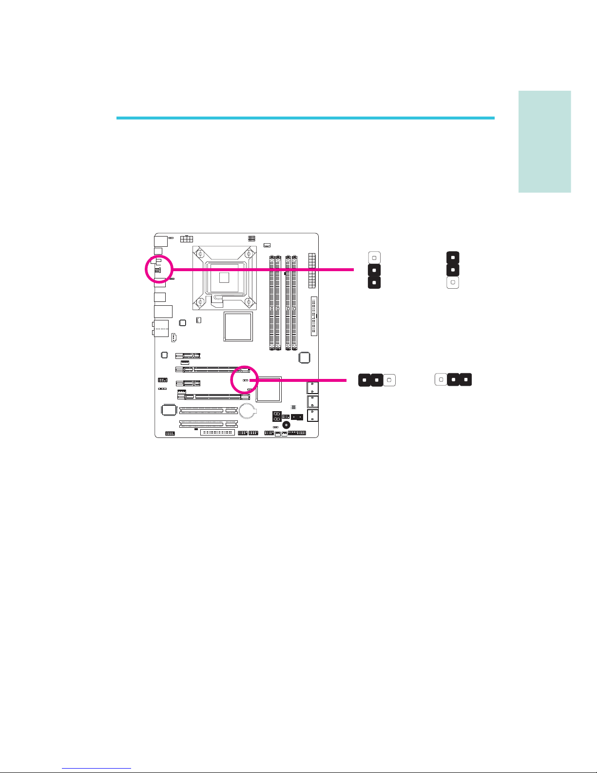
S
Español
87
Español
Chapter 2 - Instalación del Hardware
Puente
En alguno de los siguientes casos,
a) los datos CMOS se corrompen.
b) ha olvidado la contraseña del supervisor o del usuario.
c) La configuración de overlock en el BIOS causó inestabilidad en el
sistema o problemas en el inicio del mismo.
Se puede configurar nuevamente el sistema con los valores
predeterminados almacenados en la ROM BIOS.
Acceso al JP8 desde el panel trasero del sistema. Esto le
proporciona comodidad al permitirle borrar los CMOS sin tener que
quitar la tapa de la carcasa.
Borrar Datos CMOS
Limpieza de datos CMOS Data utilizando Jumpers
2-3 On
(encendido):
Borrar datos
CMOS
1-2 On
(encendido):
Normal
(predeterminado)
2-3 On
(encendido):
Borrar datos
CMOS
1-2 On
(encendido):
Normal
(predeterminado)
JP2
JP8
X
1
3
2
1
3
2
X
3
123
1
2
Page 88

Español
S
88
Español
Para cargar los valores predeterminados almacenados en la ROM
BIOS, siga los siguientes pasos.
1. Apague el sistema y desenchufe el cable de alimentación.
2. Coloque en posición de encendido los pines JP2/JP8 2 y 3.
Aguarde unos segundos y vuelva el JP2/JP8 nuevamente a su
configuración predeterminada, pines 1 y 2 encendidos.
3. Luego, enchufe el cable de alimentación y encienda el sistema.
Page 89
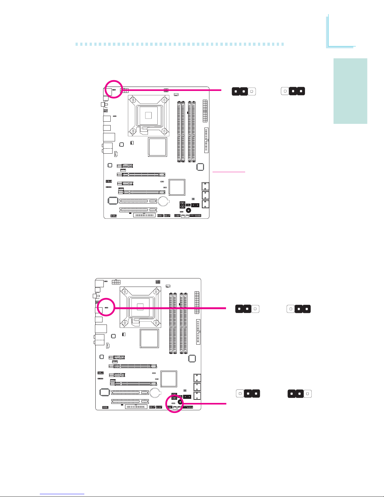
S
Español
89
Español
Selector de Alimentación PS/2
Seleccionar 5VSB le permitirá utilizar el teclado PS/2 o el ratón PS/2
para despertar el sistema.
Selector de Alimentación USB
Importante:
La fuente de alimentación 5VSB de
suministro eléctrico debe admitir
≥720mA.
1-2 On: 5V
(predeterminado)
1-2 On: 5V
(predeterminado)
1-2 On: 5V
(predeterminado)
2-3 On:
5VSB
2-3 On: 5VSB
2-3 On:
5VSB
X
JP7
3
123
1
2
X
USB 6-11
(JP5)
X
USB 0-5
(JP6)
312 312
31
2
312
Page 90
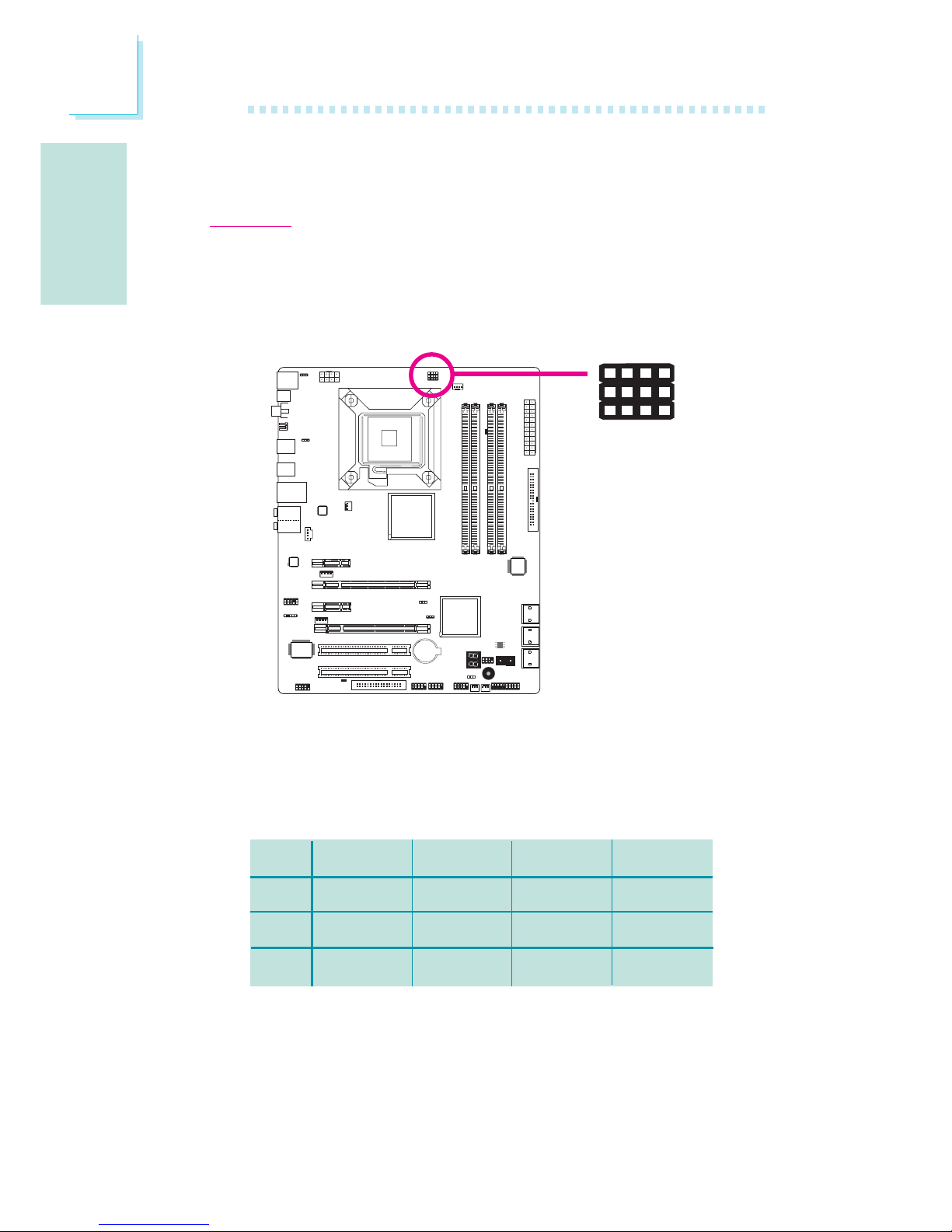
Español
S
90
Español
Seleccionar 5VSB le permitirá utilizar el teclado USB o el ratón USB
para despertar el sistema.
Importante:
La fuente de alimentación 5VSB de suministro eléctrico debe admitir ≥1.5A.(2
puertos) o ≥A (3 o más puertos USB).
Por defecto, los tres jumpers están configurados para las clavijas 1 y
2 Encendidas. Esta configuración permite que el sistema se ejecute
automáticamente según el FSB de la CPU. Si quiere cambiar la
configuración, por favor consulte la tabla a continuación.
JP17
JP18
JP19
Por la CPU
1-2 On
1-2 On
1-2 On
FSB 800
2-3 On
3-4 On
2-3 On
FSB 1066
2-3 On
2-3 On
2-3 On
FSB 1333
2-3 On
2-3 On
3-4 On
Selección de FBS CPU
X
JP17
423
JP18
JP19
1
Page 91
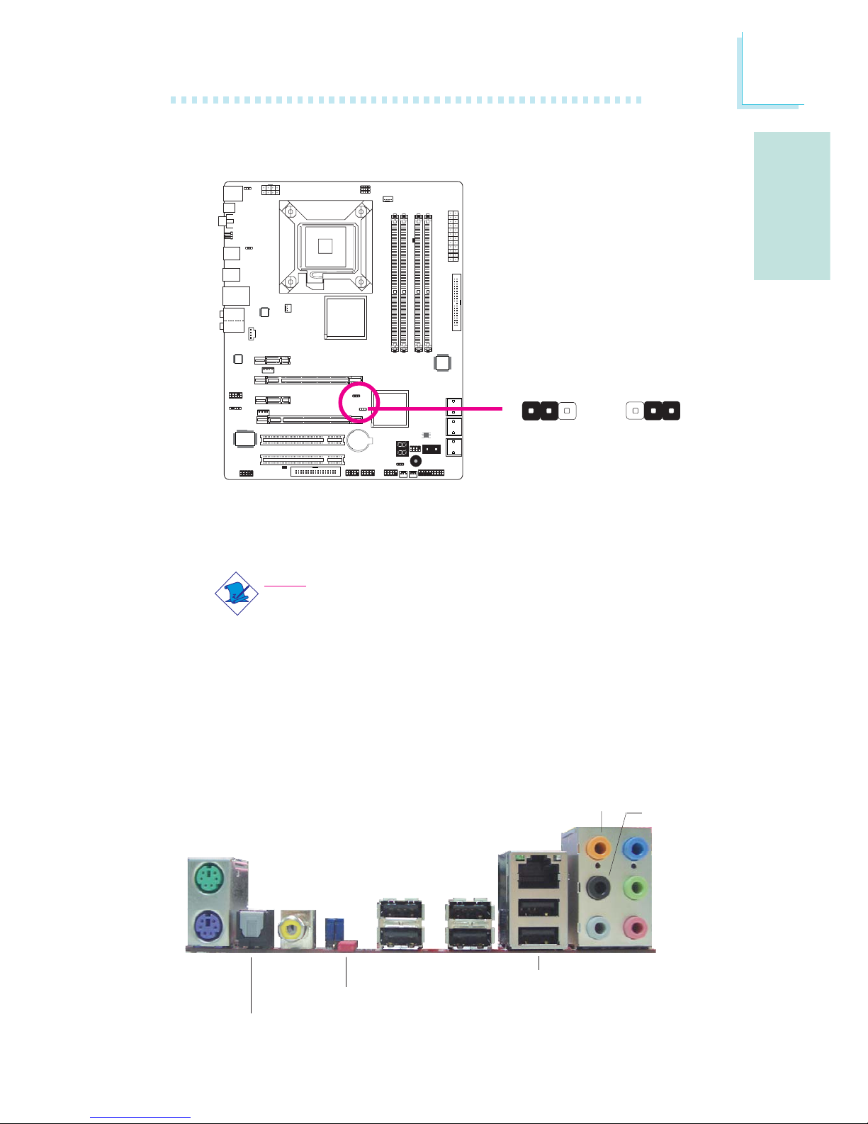
S
Español
91
Español
Puertos I/O del Panel Posterior
Restaurar RTC Secundario
Cuando haya quitado la batería RTC, este jumper restaura los bits
del registro de manejabilidad en la RTC.
Nota:
1. La entrada SRTCRST# debe estar siempre alta cuando todos
los demás planes de energía RTC están activados.
2. En caso de que la batería RTC esté agotada o no esté en
la plataforma, debe subir la clavija SRTCRST# antes de la
clavija RSMRST# .
1-2 On
(encendido):
Normal
(predeterminado)
2-3 On:
RTC reset
óptico
S/PDIF
USB 10-11
USB 6-7
Mic-in
Side R/L
Center/
Subwoofer
Rear R/L
Line-in
Front R/L
LAN
ratón
PS/2
USB 8-9
Clear
CMOS
jumper
coaxiales
RCA
S/PDIF
teclado
PS/2
X
JP12
1
3
2
13
2
Page 92
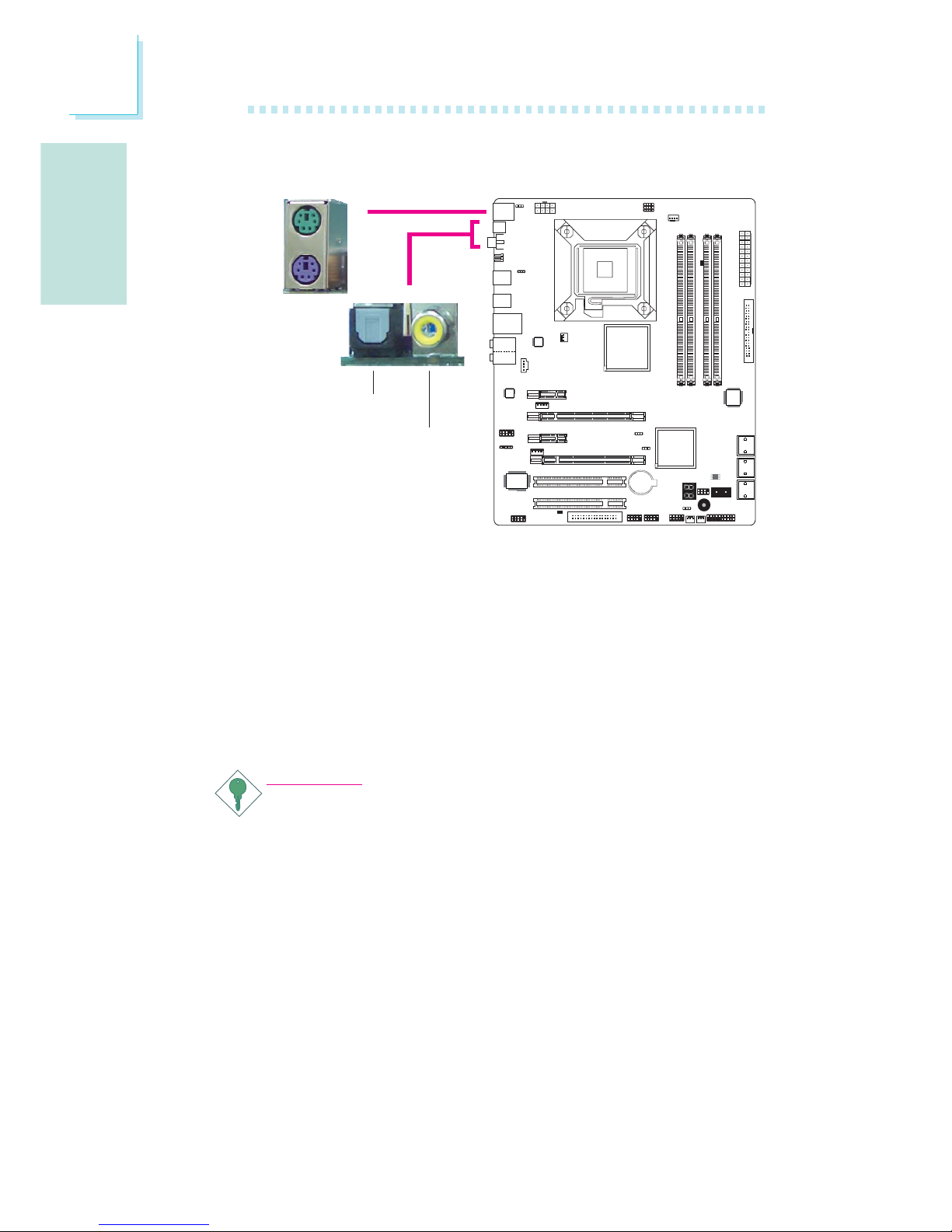
Español
S
92
Español
Puertos para Ratón PS/2 y Teclado PS/2
Estos puertos se utilizan para conectar un ratón PS/2 y un teclado
PS/2.
Enchufes coaxiales RCA S/PDIF y óptico S/PDIF
Estos enchufes se utilizan para conectar dispositivos de salida de
audio externos mediante cables coaxiales/óptico S/PDIF.
Importante:
NO utilice S/PDIF óptico y S/PDIF RCA coaxial al mismo
tiempo.
Puertos PS/2 y Puertos S/PDIF
W
PS/2 Mouse
PS/2 KB
óptico
S/PDIF
Coaxial RCA
S/PDIF
W
Page 93
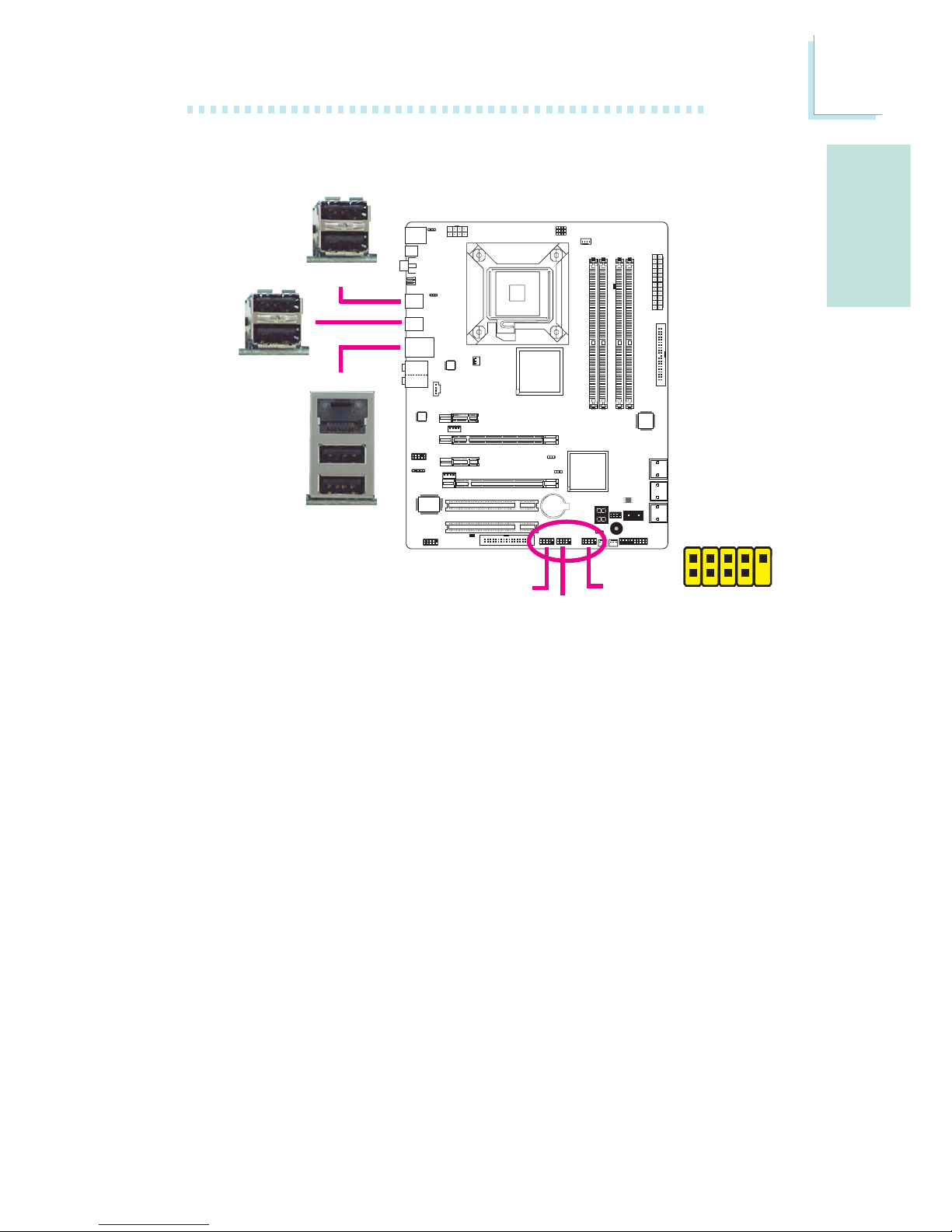
S
Español
93
Español
Puertos USB y Puertos LAN
Puertos USB
Los puertos USB se utilizan para conectar dispositivos USB 2.0/1.1
El conector de 10 pines permite conectar 6 puertos USB 2.0/1.1
adicionales. El puerto USB puede presentarse montado en un
soporte con bordes de placa. Instale dicho soporte en una ranura
disponible en la parte trasera del armazón del sistema, luego
conecte los cables del puerto USB a estos conectores.
Puertos LAN
Los puertos LAN permiten a la placa del sistema conectarse a una
red de área local mediante un concentrador de red.
1
VCC
-Data
+Data
GND
Key
VCC
-Data
+Data
GND
N. C.
2
10
9
W
USB 4-5
W
USB 0-1
USB 9
W
LAN
USB 8
USB 11
USB 10
USB 7
USB 6
USB 2-3
Page 94
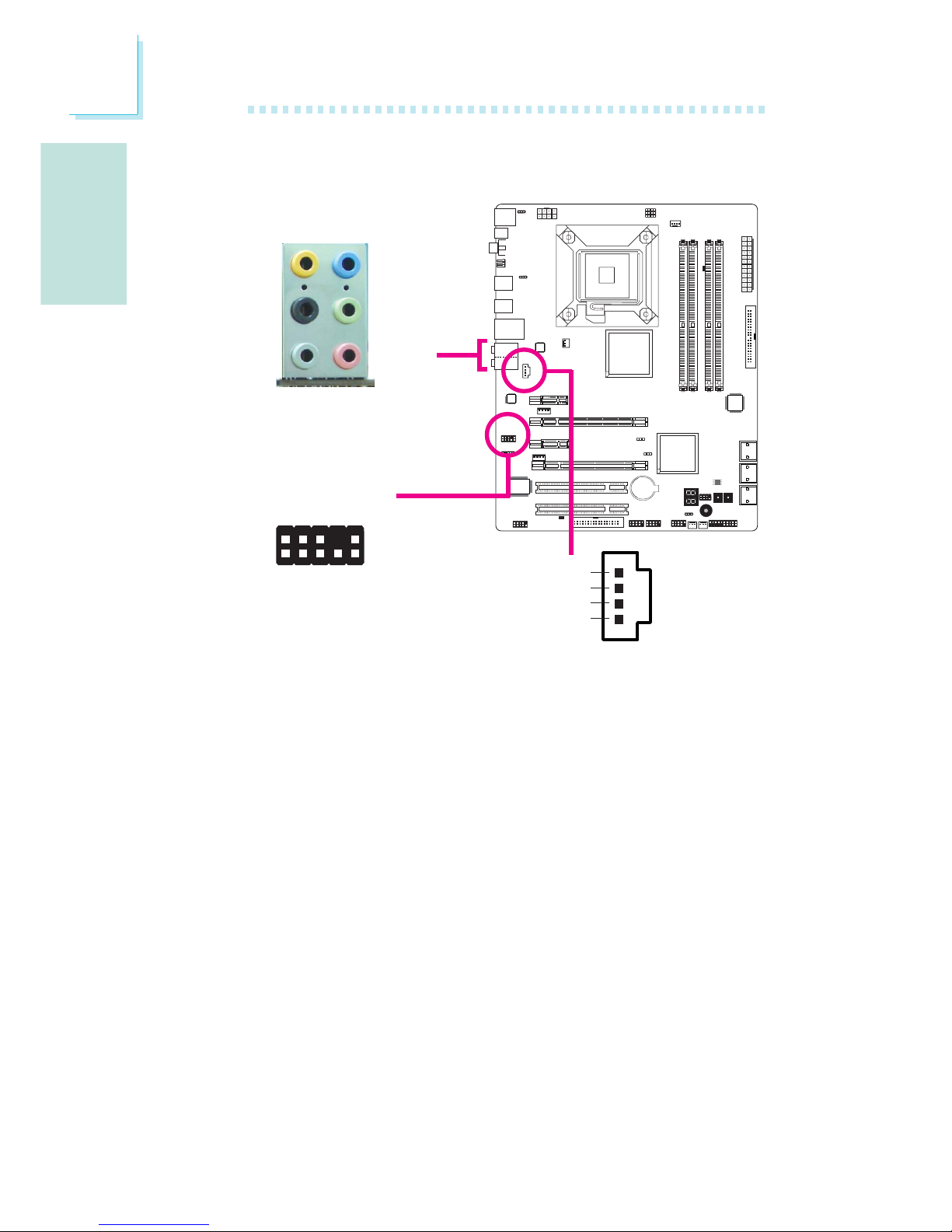
Español
S
94
Español
Audio y CD-In
Enchufe central/para altavoz de graves (naranja)
Este enchufe se utiliza para conectar los altavoces central y de
graves del sistema de audio.
Enchufe trasero izquierdo/derecho (negro)
Este enchufe se utiliza para conectar los altavoces trasero derecho y
trasero izquierdo del sistema de audio.
Enchufe lateral izquierdo/derecho (gris)
Este enchufe se utiliza para conectar los altavoces lateral derecho y
lateral izquierdo del sistema de audio.
Enchufe de entrada (azul claro)
Este enchufe se utiliza para conectar cualquier dispositivo de audio,
tal como un hi-fi, un reproductor de CD, un reproductor de cintas,
sintonizador de radio AM/FM, un sintetizador, etc.
Enchufe de salida (verde lima)
Este enchufe se utiliza para conectar los altavoces frontal derecho y
frontal izquierdo del sistema de audio.
W
W
Rear audio
Front audio
Front R/L
Line-in
Mic-in
Rear R/L
Center/
Subwoofer
Side R/L
1
2
10
Mic-L
Mic-R
Line-out-R
Front-sense
Line-out-L
GND
Presense-signal
Mic-jack-sense
Key
Line-out-jack-sense
9
4
1
Left audio channel
Right audio channel
Ground
Ground
W
CD-in
Page 95
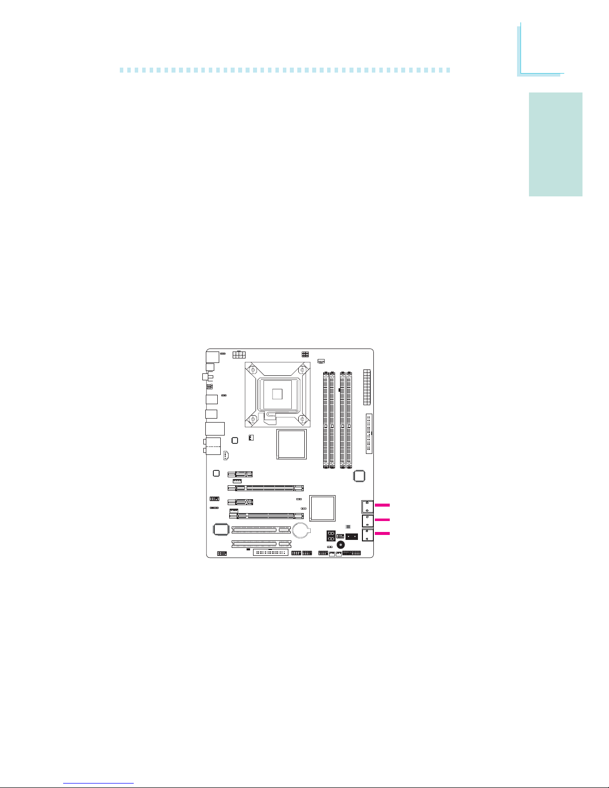
S
Español
95
Español
Conectores ATA Seriales
Los conectores seriales ATA (SATA) se utilizan para conectar los
transmisores ATA seriales. Conecte un extremo del cable ATA serial
al conector ATA serial y el otro extremo al dispositivo ATA serial.
Configuración del RAID
Consulte el capítulo sobre RAID en este manual para obtener más
información sobre la creación de RAID en dispositivos ATA seriales.
Conectores I/O
Enchufe de entrada de micrófono (rosa)
Este enchufe se utiliza para conectar un micrófono externo.
Conector de audio frontal
El conector de audio frontal se utiliza para conectar a los enchufes
de entrada de línea y de entrada de micrófono en el panel frontal
de su sistema.
Conector de entrada de CD
El conector de entrada de CD se utiliza para recibir audio de un
lector de CD-ROM, de un sintonizador de TV o de una placa
MPEG.
SATA 2-3
SATA 0-1
SATA 4-5
Page 96
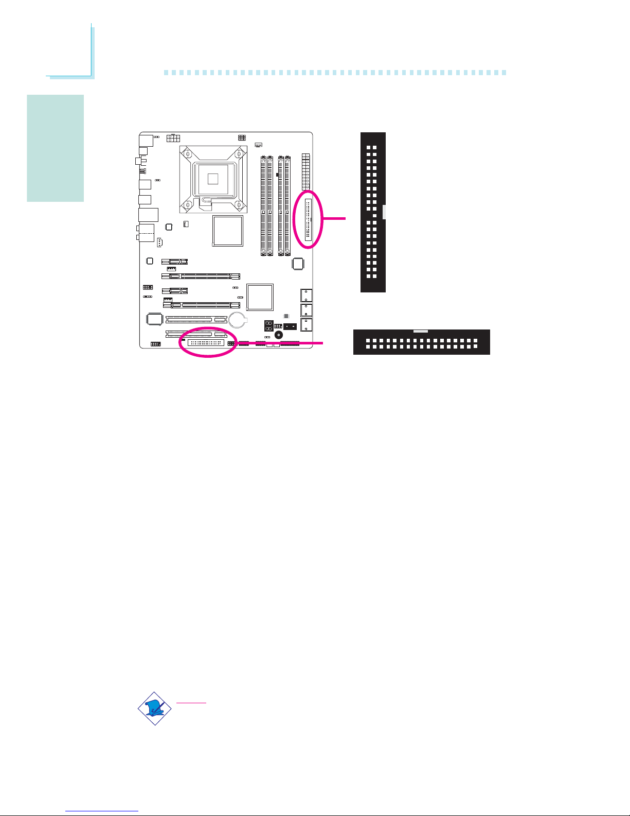
Español
S
96
Español
Conector de la Unidad de Disco Flexible y Conector IDE
Conector de Disco Flexible
El conector de disco flexible de se utiliza para conectar una unidad
de discos flexibles. Cuenta con un mecanismo de codificación para
prevenir una instalación inadecuada del cable flexible. Inserte un
extremo del cable flexible en este conector y el otro conector del
extremo a la unidad de discos flexibles. El extremo de color del
cable debe estar alineado con el pin1 de este conector.
Conector de Unidad de Discos IDE
El conector de la unidad de discos IDE se utiliza para conectar dos
unidades de discos IDE. Cuenta con un mecanismo de codificación
para prevenir una instalación inadecuada del cable IDE. Un cable IDE
incluye 3 conectores, uno que se inserta en este conector y los otros
dos que se insertan en los dispositivos IDE. El conector en el
extremo del cable corresponde a la unidad principal y el conector en
el medio del cable corresponde a la unidad secundaria. El extremo
de color del cable debe estar alineado con el pin1 de este conector.
Nota:
Al utilizar dos unidades IDE, una de ellas se debe configurar
como principal y la otra como secundaria. Siga las instrucciones
del fabricante de la unidad para configurar los puentes de
conexión y/o los interruptores de las unidades.
X
40
39
21
X
IDE
FDD
34
33
1
2
Page 97
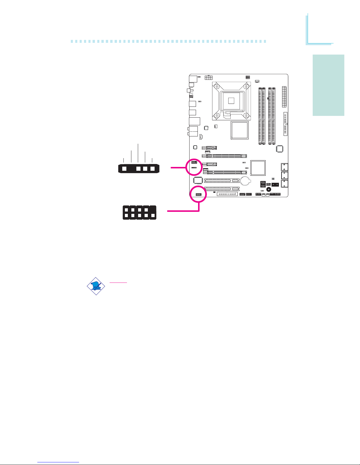
S
Español
97
Español
Conectores IrDA y Serial (COM)
Conectore IrDA
Este conector se utiliza para conectar un módulo IrDA.
Nota:
La secuencia de las funciones de pin en algún cable IrDA se
puede revertir desde la función de pin definida en la placa del
sistema. Asegúrese de conectar el conector del cable al
conector IrDA de acuerdo a sus funciones de pin.
Es posible que necesite instalar los controladores adecuados en el
sistema operativo para utilizar la función IrDA. Consulte el manual o
la documentación de su sistema operativo para obtener más
información.
Conector Serial (COM)
El conector (COM) serial se utiliza para conectar módems,
impresoras seriales, pantallas remotas u otros dispositivos seriales. El
puerto COM puede presentarse montado en un soporte con
bordes de placa. Instale dicho soporte en una ranura disponible en
la parte trasera del armazón del sistema, luego conecte el cable del
W
1
9
2
CD
TD
RD
DTR
GND
RTS
DSR
CTS
RI
COM
15
VCC
N. C.
IRRX
Ground
IRTX
IrDA
X
Page 98
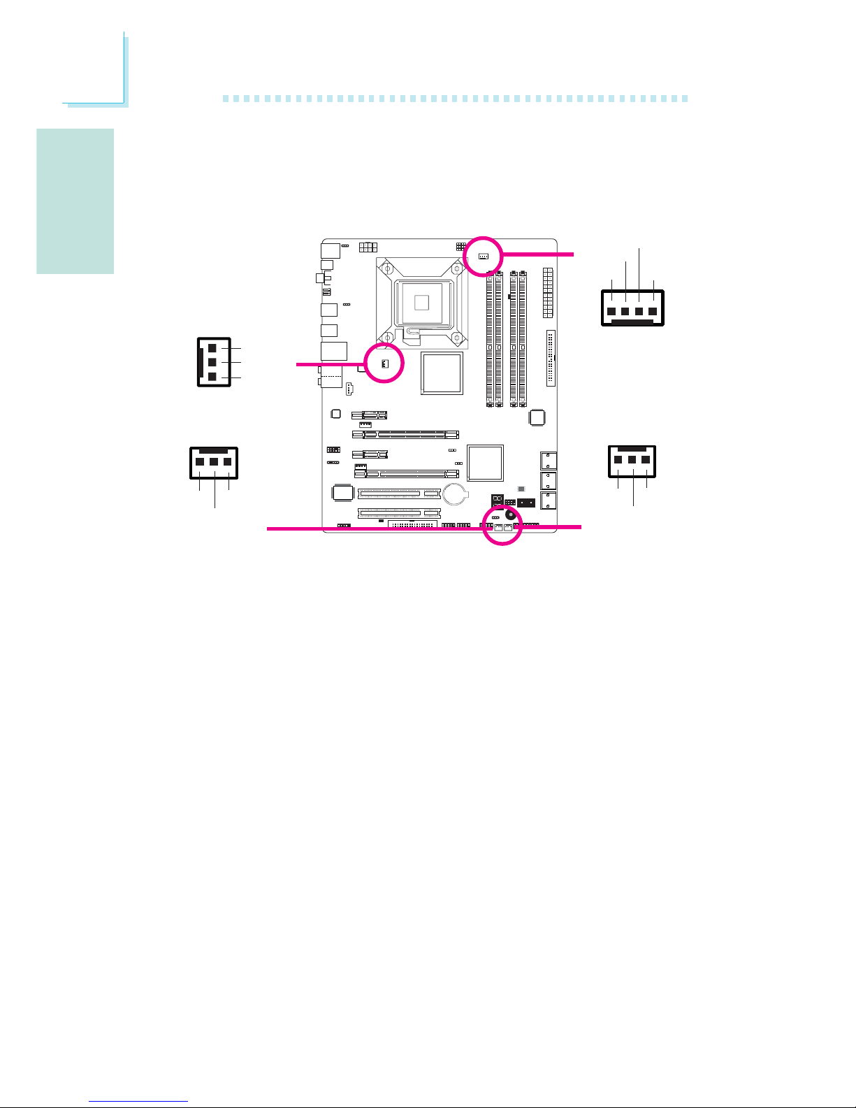
Español
S
98
Español
Conectores de Ventiladores de Refrigeración
Estos conectores de ventiladores se utilizan para conectar
ventiladores de refrigeración. Los ventiladores de refrigeración
proporcionan una circulación de aire adecuada a través del armazón
a fin de prevenir que recalienten los componentes de la placa de
sistema y la CPU.
puerto serial a ese conector. El extremo de color del cable debe
estar alineado con el pin1 de este conector.
X
X
CPU fan
Chassis fan
System fan
X
NB fan
1
3
Sense
Power
On/Off
4
1
Sense
Power
Ground
Speed
Control
3
1
Ground
Power
Sense
X
3
1
Ground
Power
Sense
Page 99
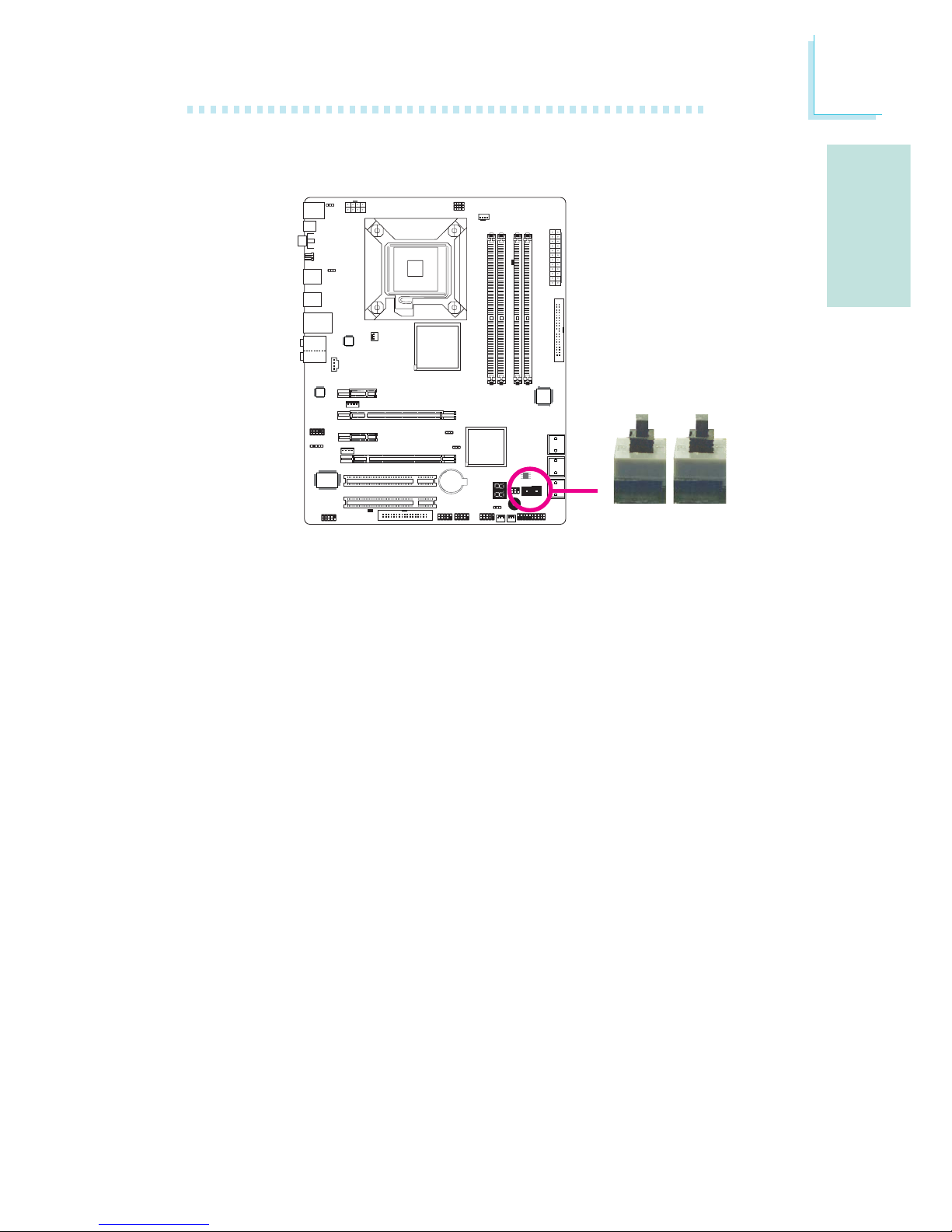
S
Español
99
Español
Interruptores Sensibles al Tacto EZ
La inclusión de los interruptores power y reset en la placa del
sistema resulta útil especialmente para los usuarios que realizan las
conexiones ellos mismos. Son convenientes al encender y/o reiniciar
el sistema mientras se ajusta la placa del sistema antes de instalarla
en el armazón del sistema.
X
Reset Power
Page 100
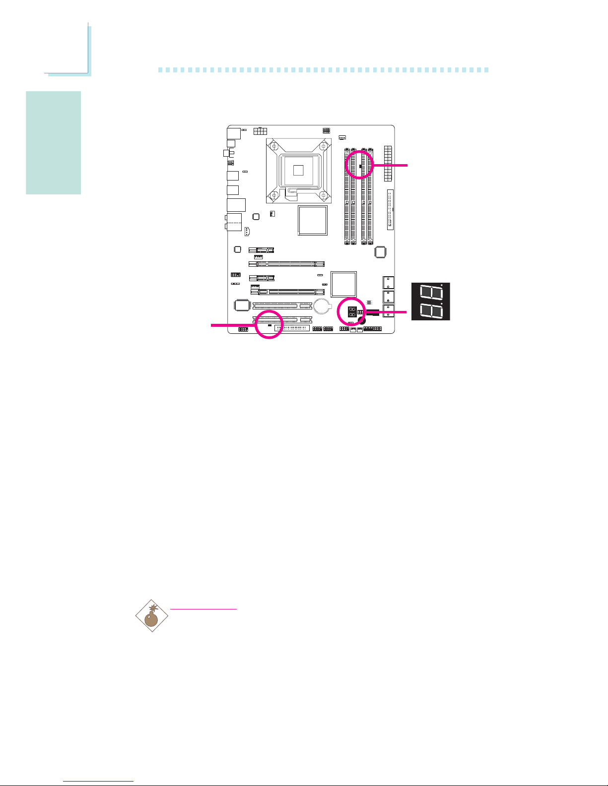
Español
S
100
Español
LED
LED de Encendido DRAM
Este LED se iluminará cuando se encienda el sistema.
LED de Alimentación de Reserva
Este LED se iluminará cuando el sistema se encuentre en modo de
reserva.
LED de Diagnóstico
El LED de diagnóstico muestra códigos POST. Los POST
(Autodiagnósticos en encendido) que los controla el BIOS se
efectúan cada vez que el sistema está encendido. POST detectarán
el estado del sistema y sus componentes. Cada código del LED
corresponde a un estado del sistema determinado.
Advertencia:
Cuando el LED de encendido DRAM y/o el LED de
alimentación de reserva se encienden en rojo, ésto indica que
hay electricidad en el enchufe DIMM y/o en las ranuras PCI.
Apague el PC, luego desenchufe el cable de alimentación antes
de instalar módulos de memoria o placas complementarias. No
hacerlo causará daños graves a la placa madre y a sus
componentes.
.
.
.
.
.
.
.
.
LED de
alimentación
de reserva
LED de
encendido
DRAM
LED de
diagnóstico
 Loading...