

LANPARTY NFII ULTRA B User Guide

Rev. A+
System Board
User’s Manual
75300331

Copyright
This publication contains information that is protected by copyright. No part of it may be reproduced in any form or by any
means or used to make any transformation/adaptation without
the prior written permission from the copyright holders.
This publication is provided for informational purposes only. The
manufacturer makes no representations or warranties with respect to
the contents or use of this manual and specifically disclaims any
express or implied warranties of merchantability or fitness for any
particular purpose. The user will assume the entire risk of the use or
the results of the use of this document. Further, the manufacturer
reserves the right to revise this publication and make changes to its
contents at any time, without obligation to notify any person or
entity of such revisions or changes.
© 2003 All Rights Reserved.
Trademarks
Microsoft® MS-DOS®, WindowsTM, Windows® 95, Windows® 98,
Windows® 98 SE, Windows® ME, Windows® 2000, Windows NT
4.0 and Windows® XP are registered trademarks of Microsoft
Corporation. AMD, AthlonTM XP and AthlonTM are registered
trademarks of Advanced Micro Devices, Inc. nVIDIA® is a registered trademark of NVIDIA Corporation. Award is a registered
trademark of Award Software, Inc. Other trademarks and registered trademarks of products appearing in this manual are the
properties of their respective holders.
Caution
To avoid damage to the system:
• Use the correct AC input voltage range
To reduce the risk of electric shock:
• Unplug the power cord before removing the system chassis
cover for installation or servicing. After installation or servicing,
cover the system chassis before plugging the power cord.
..
.
..
®

Battery:
• Danger of explosion if battery incorrectly replaced.
• Replace only with the same or equivalent type recommend
the manufacturer.
• Dispose of used batteries according to the battery
manufacturer’s
Joystick or MIDI port:
• Do not use any joystick or MIDI device that requires more than
10A current at 5V DC. There is a risk of fire for devices that
exceed this limit.
instructions.
FCC and DOC Statement on Class B
This equipment has been tested and found to comply with the limits
for a Class B digital device, pursuant to Part 15 of the FCC rules.
These limits are designed to provide reasonable protection against
harmful interference when the equipment is operated in a residential
installation. This equipment generates, uses and can radiate radio
frequency energy and, if not installed and used in accordance with
the instruction manual, may cause harmful interference to radio
communications. However, there is no guarantee that interference
will not occur in a particular installation. If this equipment does cause
harmful interference to radio or television reception, which can be
determined by turning the equipment off and on, the user is
encouraged to try to correct the interference by one or more of the
following measures:
by
• Reorient or relocate the receiving antenna.
• Increase the separation between the equipment and the receiver.
• Connect the equipment into an outlet on a circuit different from
that to which the receiver is connected.
• Consult the dealer or an experienced radio TV technician for
help.
Notice:
1. The changes or modifications not expressly approved by the
party responsible for compliance could void the user's authority
to operate the equipment.
2. Shielded interface cables must be used in order to comply with
the emission limits.

Notice
This user’s manual contains detailed information about the system
board. If, in some cases, some information doesn’t match those
shown in the multilingual manual, the multilingual manual should
always be regarded as the most updated version. The multilingual
manual is included in the system board package.
To view the user’s manual, insert the CD into a CD-ROM drive. The
autorun screen (Mainboard Utility CD) will appear. Click the
“TOOLS” icon then click “Manual” on the main menu.

Table of Contents
Chapter 1 - Introduction
1.1 Features and Specifications.................................................................................
1.2 Package Checklist.........................................................................................................
Chapter 2 - Hardware Installation
2.1 System Board Layout ........................................................................................
2.2 Installing the CPU....................................................................................................
2.3 System Memor y........................................................................................................
2.4 Jumper Settings...........................................................................................................
2.5 Rear Panel I/O Ports............................................................................................
2.6 I/O Connectors..........................................................................................................
Chapter 3 - Award BIOS Setup Utility
3.1 The Basic Input/Output System....................................................................
3.1.1 Standard CMOS Features.............................................................
3.1.2 Advanced BIOS Features..............................................................
3.1.3 Advanced Chipset Features .....................................................
3.1.4 Integrated Peripherals........................................................................
3.1.5 Power Management Setup..........................................................
3.1.6 PnP/PCI Configurations....................................................................
3.1.7 PC Health Status...................................................................................
3.1.8 Genie BIOS Setting.............................................................................
3.1.9 CMOS Reloaded.....................................................................................
3.1.10 Load Optimized Defaults..............................................................
3.1.11 Set Supervisor Password...............................................................
3.1.12 Set User Password..............................................................................
3.1.13 Save & Exit Setup.................................................................................
3.1.14 Exit Without Saving.............................................................................
3.2 Sil3114 SataRAID BIOS...........................................................................................
3.3 Selecting the First Boot Device During POST.............................
3.4 Updating the BIOS.......................................................................................................
7
15
16
17
20
24
27
37
52
53
58
62
66
72
77
79
81
85
87
88
89
90
91
92
92
93

1
Introduction
Chapter 4 - Supported Softwares
4.1 Desktop Management Interface..................................................................
4.2 Drivers, Utilities and Software Applications..................................
4.3 Installation Notes........................................................................................................
Appendix A - Using the Suspend to RAM
Function
A.1 Using the Suspend to RAM Function..................................................
Appendix B - System Error Messages
B.1 POST Beep......................................................................................................................
B.2 Error Messages.............................................................................................................
Appendix C - Troubleshooting
C.1 Troubleshooting Checklist...................................................................................
95
98
110
111
115
115
117
6

Introduction
Chapter 1 - Introduction
1.1 Features and Specifications
1.1.1 Features
Chipset
• nVIDIA® nForce2 chipset
- nForce2 Ultra 400
- nForce2 MCP-T
Processor
The system board is equipped with Socket-A for PGA processor.
It is also equipped with a switching voltage regulator that automatically detects 1.100V to 1.850V.
1
• AMD AthlonTM XP 266/333/400MHz FSB
• AMD Athlon
• AMD Duron
TM
200/266MHz FSB
TM
200/266MHz FSB
Important:
To ensure proper boot up and operation of your system, you
must power-off the system then turn off the power supply’s
switch or unplug the AC power cord prior to replacing the CPU.
System Memory
• Supports dual channel memory interface
• Supports up to 3GB memory (unbuffered DIMM)
• Suppor ts PC1600 (DDR200), PC2100 (DDR266), PC2700
(DDR333) and PC 3200 (DDR 400) DDR SDRAM DIMM,
2.5V type
• Three 184-pin DDR SDRAM DIMM sockets
DIMMs
2MBx64
4MBx64
8MBx64
Memory Size
16MB
32MB
64MB
DIMMs
16MBx64
32MBx64
64MBx64
Memory Size
128MB
256MB
512MB
7

1
Introduction
Expansion Slots
• 1 AGP slot
• 5 PCI slots
AGP (Accelerated Graphics Port)
AGP is an interface designed to support high performance 3D
graphics cards. It utilizes a dedicated pipeline to access system
memory for texturing, z-buffering and alpha blending. The AGP slot
supports AGP 8x with up to 2132MB/sec. bandwidth and AGP 4x
with up to 1066MB/sec. bandwidth for 3D graphics applications.
AGP in this system board will deliver faster and better graphics to
your PC.
Onboard Audio Features
• Realtek ALC650
• AC’97 2.2 S/PDIF extension compliant codec
• Supports Microsoft® DirectSound/DirectSound 3D
• AC’97 supported with full duplex, independent sample rate
converter for audio recording and playback
• S/PDIF-in/out interface
• 6-channel audio output
S/PDIF
S/PDIF is a standard audio file transfer format that transfers digital
audio signals to a device without having to be converted first to
an analog format. This prevents the quality of the audio signal
from degrading whenever it is converted to analog. S/PDIF is usually found on digital audio equipment such as a DAT machine or
audio processing device. The S/PDIF connector on the system
board sends surround sound and 3D audio signal outputs to amplifiers and speakers and to digital recording devices like CD recorders.
6-channel Audio
The center/bass and rear out jacks which support four audio output signals: center channel, subwoofer, rear right channel and rear
left channel; together with the line-out (2-channel) jack support
6-channel audio output.
8

Introduction
Onboard Dual LAN Features
• nVIDIA® nForce2 MCP-T and ICS1893 Phy
- Full duplex support at both 10 and 100 Mbps
• Realtek RTL8110S Gigabit LAN
- Full duplex support at 10, 100 and 1000 Mbps
• Integrated IEEE 802.3, 10BASE-T and 100BASE-TX compatible
PHY
• Integrated power management functions
• Supports IEEE 802.3u auto-negotiation
PCI Bus Master IDE Controller
• Supports ATA/33, ATA/66, ATA/100 and ATA/133 hard drives
• UDMA Modes 3, 4, 5 and 6 Enhanced IDE (data transfer rate
up to 133MB/sec.)
• Bus mastering reduces CPU utilization during disk transfer
• Supports ATAPI CD-ROM, LS-120 and ZIP
SATA IDE/RAID Interface
• Silicon Image Sil3114 PCI to Serial ATA controller
• Supports four SATA (Serial ATA) interfaces which are compliant with SATA 1.0 specification (1.5Gbps interface)
• Supports RAID 0 and RAID 1
1
Serial ATA (SATA) is a storage interface that is compliant with
SATA 1.0 specification. With speed of up to 1.5Gbps, it improves
hard drive performance even in data intensive environments such
as audio/video, consumer electronics and entry-level servers.
IEEE 1394 Interface
• nVIDIA® nForce2 MCP-T and Agere FW803 Phy chips
• Supports three 100/200/400 Mb/sec ports
IEEE 1394 is fully compliant with the 1394 OHCI (Open Host
Controller Interface) 1.1 specification. It suppor ts up to 63 devices that can run simultaneously on a system. 1394 is a fast external bus standard that supports data transfer rates of up to
400Mbps. In addition to its high speed, it also supports isochronous data transfer which is ideal for video devices that need
to transfer high levels of data in real-time. 1394 supports both
Plug-and-Play and hot plugging.
9

1
Introduction
IrDA Interface
The system board is equipped with an IrDA connector for wireless connectivity between your computer and peripheral devices.
The IRDA (Infrared Data Association) specification supports data
transfers of 115K baud at a distance of 1 meter.
USB Ports
The system board supports USB 2.0 and USB 1.1 ports. USB 1.1
supports 12Mb/second bandwidth while USB 2.0 supports 480Mb/
second bandwidth providing a marked improvement in device
transfer speeds between your computer and a wide range of
simultaneously accessible external Plug and Play peripherals..
BIOS
• Award BIOS, Windows® 95/98/2000/ME/XP Plug and Play
compatible
• Genie BIOS provides:
- CPU/DRAM/AGP overclocking
- CPU/AGP/DRAM/Chipset overvoltage
• Supports SCSI sequential boot-up
• Flash EPROM for easy BIOS upgrades
• Supports DMI 2.0 function
• 4Mbit flash memory
10
Desktop Management Interface (DMI)
The system board comes with a DMI 2.0 built into the BIOS. The
DMI utility in the BIOS automatically records various information
about your system configuration and stores these information in the
DMI pool, which is a part of the system board's Plug and Play
BIOS. DMI, along with the appropriately networked software, is
designed to make inventory, maintenance and troubleshooting of
computer systems easier.

Introduction
Rear Panel I/O Ports (PC 99 color-coded connectors)
• 1 PS/2 mouse port
• 1 PS/2 keyboard port
• 1 DB-9 serial port
• 1 DB-25 parallel port
• 4 USB 2.0/1.1 ports
• 2 RJ45 LAN ports
• 2 S/PDIF RCA jacks (S/PDIF-in and S/PDIF-out)
• 3 audio jacks: line-out, line-in and mic-in
• 2 audio jacks for center/bass and rear out
I/O Connectors
• 1 connector for 2 additional external USB 2.0/1.1 ports
• 3 connectors for 3 external IEEE 1394 por ts
• 1 front audio connector for external line-out and mic-in jacks
• 2 internal audio connectors (AUX-in and CD-in)
• 1 S/PDIF connector for optical cable connection
• 1 connector for IrDA interface
• 4 Serial ATA connectors
• 2 IDE connectors
• 1 floppy connector
• 2 ATX power supply connectors
• 3 fan connectors for CPU fan, chassis fan and 2nd fan
• 4 diagnostic LEDs
• 1 diagnostic LED connector for external 4 diagnostic LEDs
display
• EZ touch switches (power switch and reset switch)
1
1.1.2 System Health Monitor Functions
The system board is capable of monitoring the following “system
health” conditions.
• Monitors CPU/system temperature
• Monitors ±12V/5V/3.3V/VBAT(V)/5VSB(V) voltages
• Monitors CPU/chassis fan speed
• Read back capability that displays temperature, voltage and fan
speed
11

1
Introduction
1.1.3 Intelligence
CPU Temperature Protection
The CPU Temperature Protection function has the capability of
monitoring the CPU’s temperature during system boot-up. To prevent CPU overheat and damage, the system will automatically
shutdown once it has detected that the CPU’s temperature exceeded the temperature limit pre-defined by the system.
Overvoltage
The Overvoltage function allows you to manually adjust to a
higher core voltage that is supplied to the CPU, AGP, DRAM and/
or chipset. Although this function is supported, we do not recommend that you use a higher voltage because unstable current
may be supplied to the system board causing damage.
Overclocking
The Overclocking function allows you to adjust the CPU and
DRAM clock. However, overclocking may result to the CPU’s or
system’s instability and are not guaranteed to provide better system performance.
12
Dual Function Power Button
Depending on the setting in the “Soft-Off By PBTN” field of the
Power Management Setup, this switch will allow the system to enter
the Soft-Off or Suspend mode.
Wake-On-Ring
This feature allows the system that is in the Suspend mode or Soft
Power Off mode to wake-up/power-on to respond to calls coming
from an external modem or respond to calls from a modem PCI
card that uses the PCI PME (Power Management Event) signal to
remotely wake up the PC.
Important:
If you are using a modem add-in card, the 5VSB power source
of your power supply must support a minimum of ≥720mA.

Introduction
Wake-On-LAN
This feature allows the network to remotely wake up a Soft
Power Down (Soft-Off) PC. It is supported via the onboard LAN
port or via a PCI LAN card that uses the PCI PME (Power Management Event) signal. However, if your system is in the Suspend
mode, you can power-on the system only through an IRQ or
DMA interrupt.
Important:
The 5VSB power source of your power supply must support
≥
720mA.
Wake-On-PS/2 Keyboard/Mouse
This function allows you to use the PS/2 keyboard or PS/2
mouse to power-on the system.
Important:
The 5VSB power source of your power supply must support
≥
720mA.
Wake-On-USB
1
This function allows you to use a USB device to wake up a
system from the S3 (STR - Suspend To RAM) state.
Important:
• If you are using the Wake-On-USB function for 2 USB ports,
the 5VSB power source of your power supply must support
≥
1.5A.
• If you are using the Wake-On-USB function for 3 or more
USB ports, the 5VSB power source of your power supply
must support ≥2A.
RTC Timer to Power-on the System
The RTC installed on the system board allows your system to
automatically power-on on the set date and time.
13

1
Introduction
ACPI
The system board is designed to meet the ACPI (Advanced Configuration and Power Interface) specification. ACPI has energy saving features that enables PCs to implement Power Management
and Plug-and-Play with operating systems that support OS Direct
Power Management. Currently, only Windows
supports the ACPI function. ACPI when enabled in the Power
Management Setup will allow you to use the Suspend to RAM
function.
With the Suspend to RAM function enabled, you can power-off
the system at once by pressing the power button or selecting
“Standby” when you shut down Windows
without having to go through the sometimes tiresome process of
closing files, applications and operating system. This is because the
system is capable of storing all programs and data files during the
entire operating session into RAM (Random Access Memory)
when it powers-off. The operating session will resume exactly
where you left off the next time you power-on the system.
Important:
The 5VSB power source of your power supply must support
≥
1A.
®®
®
®®
98SE/2000/ME/XP
®®
®
®®
98SE/2000/ME/XP
14
AC Power Failure Recovery
When power returns after an AC power failure, you may choose to
either power-on the system manually, let the system power-on
automatically or return to the state where you left off before power
failure occurs.

1.2 Package Checklist
The system board package contains the following items:
; One LANPARTY NFII ULTRA B system board
; One LANPARTY NFII ULTRA B user’s manuals
; One LANPARTY NFII ULTRA B quick installation guide
; Two Serial ATA data cables
; One Serial ATA power cable
; One card-edge bracket mounted with 2 IEEE 1394 ports
; Two IDE round cables
; One FDD round cable
; One PC Transpo kit
; One FrontX device equipped with:
- Two USB 2.0/1.1 ports
- One IEEE 1394 port
- One line-out jack
- One mic-in jack
- Four diagnostic LEDs
; One I/O shield
; One thermal paste
; One LANPARTY sticker
; One case badge
; One pack of jumper caps (five 2.54mm jumper caps)
; One “Silicon Image Sil3114 RAID Drivers” diskette
; One “Mainboard Utility” CD
; One “WinDVD/WinRIP Utility” CD
Introduction
1
If any of these items are missing or damaged, please contact your
dealer or sales representative for assistance.
15
2
Hardware Installation
Chapter 2 - Hardware Installation
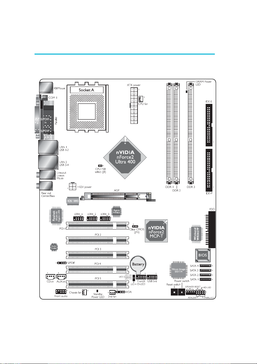
2.1 System Board Layout
16
Hardware Installation
.
.
.
Warning:
.
.
.
.
.
Electrostatic discharge (ESD) can damage your system board, processor, disk drives, add-in boards, and other components. Perform the
upgrade instruction procedures described at an ESD workstation only.
If such a station is not available, you can provide some ESD protection
by wearing an antistatic wrist strap and attaching it to a metal part
of the system chassis. If a wrist strap is unavailable, establish and
maintain contact with the system chassis throughout any procedures
requiring ESD protection.
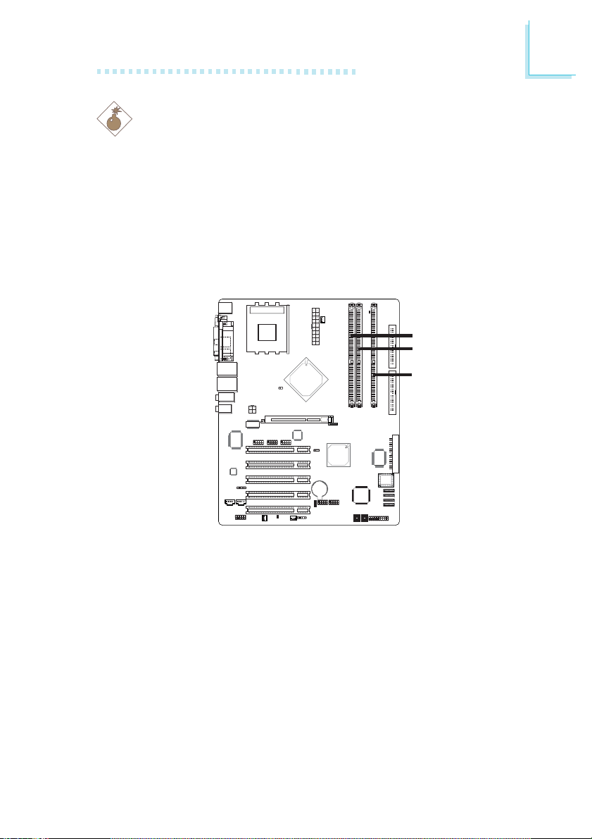
2.2 System Memory
DDR 1
DDR 2
DDR 3
2
The system board supports DDR SDRAM DIMM. Double Data
Rate SDRAM (DDR SDRAM) is a type of SDRAM that doubles
the data rate through reading and writing at both the rising and
falling edge of each clock. This effectively doubles the speed of
operation therefore doubling the speed of data transfer.
Refer to chapter 1 (System Memory section) for detailed specification of the memory supported by the system board.
The three DDR DIMM sockets on the system board are divided
into 2 channels:
1st channel - DDR 1 and DDR 2
2nd channel - DDR 3
17

2
Hardware Installation
The system board supports the following memory interface.
Single Channel (SC)
Data will be accessed in chunks of 64 bits (8B) from the
memory channels.
Dual Channel (DC)
Dual channel provides better system performance because it
doubles the data transfer rate.
Single Channel
Dual Channel
• DIMMs are on the same channel.
• DIMMs in a channel can be identical or
completely different. However, we
highly recommend using identical
DIMMs.
• Not all slots need to be populated.
• DIMMs of the same memor y configu-
ration are on different channels.
18
Hardware Installation
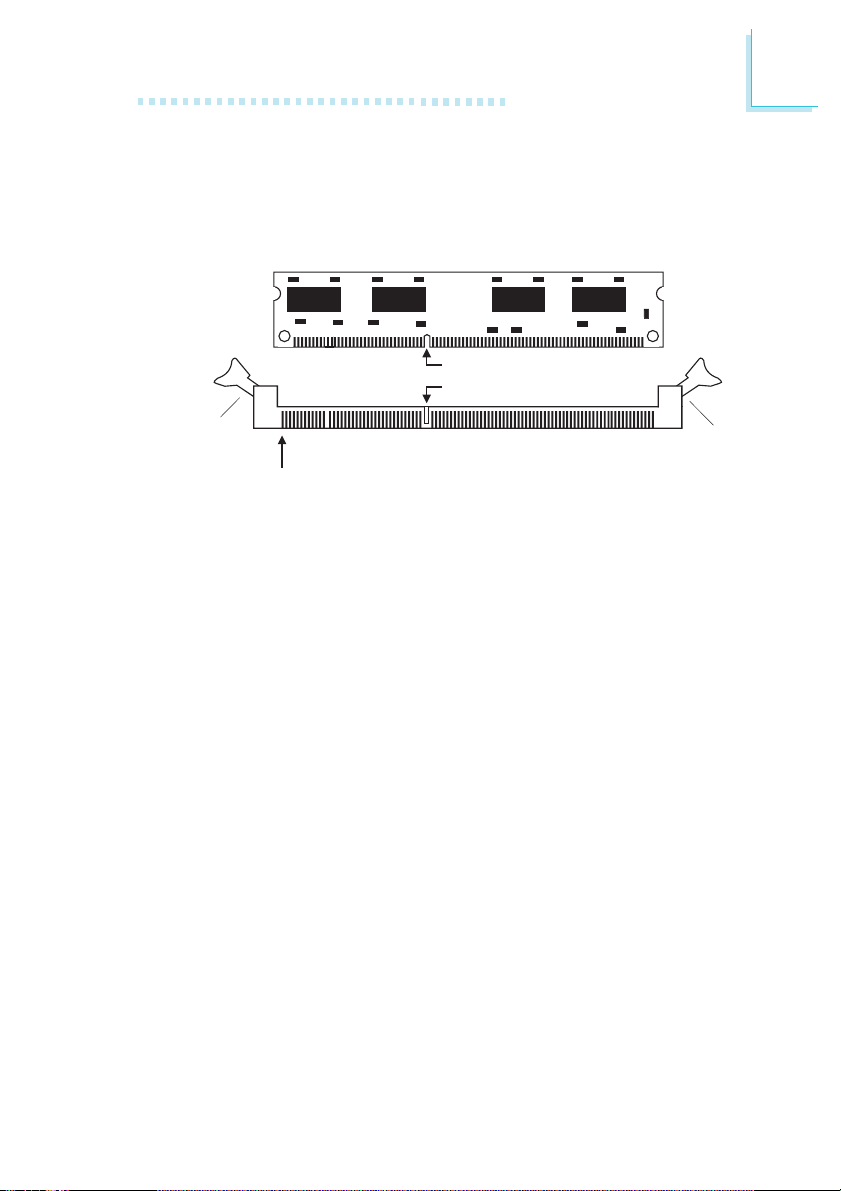
2.2.1 Installing the DIM Module
A DIM module simply snaps into a DIMM socket on the system
board. Pin 1 of the DIM module must correspond with Pin 1 of
the socket.
Notch
Key
2
Tab
Pin 1
1. Pull the “tabs” which are at the ends of the socket to the
side.
2. Position the DIMM above the socket with the “notch” in the
module aligned with the “key” on the socket.
3. Seat the module vertically into the socket. Make sure it is
completely seated. The tabs will hold the DIMM in place.
Tab
19
2
Hardware Installation
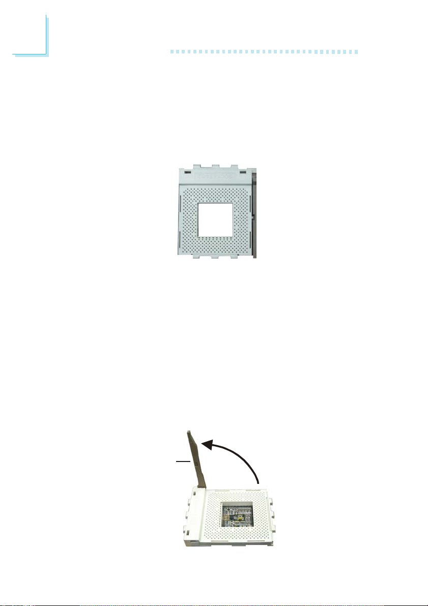
2.3 CPU
2.3.1 Overview
The system board is equipped with a surface mount Socket A
CPU socket. This socket is exclusively designed for installing an
AMD CPU.
2.3.2 Installing the CPU
1. Make sure the PC and all other peripheral devices connected
to it has been powered down.
2. Disconnect all power cords and cables.
20
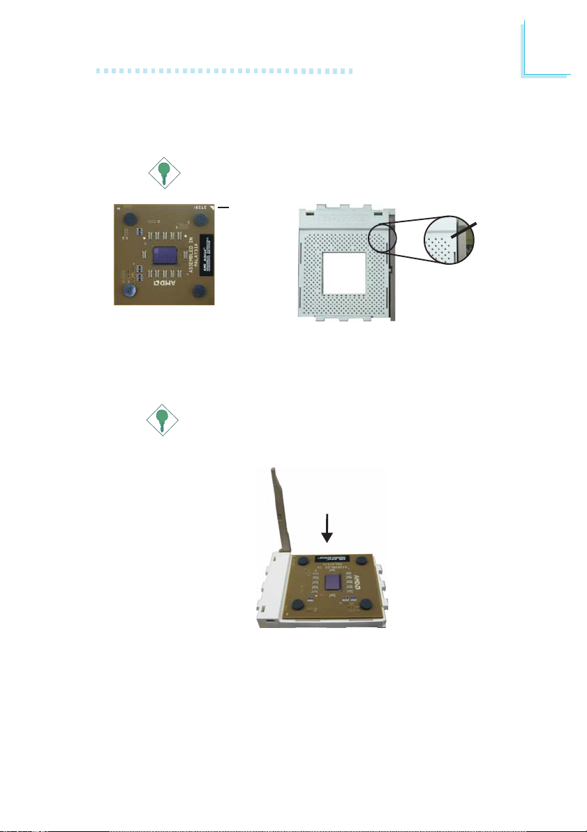
3. Locate Socket A on the system board.
4. Unlock the socket by pushing the lever sideways, away from the
socket, then lifting it up to a 90o angle. Make sure the socket is
lifted to at least this angle otherwise the CPU will not fit in
properly.
Lever
Hardware Installation
5. Position the CPU above the socket then align the gold mark
on the corner of the CPU (designated as pin 1) with pin 1 of
the socket.
Important:
Handle the CPU by its edges and avoid touching the pins.
Gold mark
Pin 1
6. Insert the CPU into the socket until it is seated in place. The
CPU will fit in only one orientation and can easily be inserted
without exerting any force.
Important:
Do not force the CPU into the socket. Forcing the CPU into
the socket may bend the pins and damage the CPU.
2
21
2
Hardware Installation
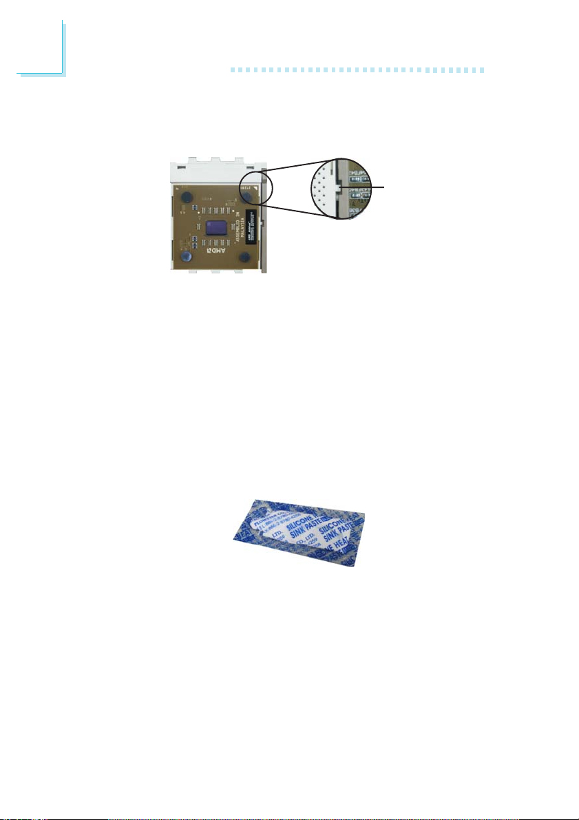
7. Once the CPU is in place, push down the lever to lock the
socket. The lever should click on the side tab to indicate that
the CPU is completely secured in the socket.
Lever lock
2.3.3 Installing the Fan and Heat Sink
The CPU must be kept cool by using a CPU fan with heat sink.
Without sufficient air circulation across the CPU and heat sink,
the CPU will overheat damaging both the CPU and system board.
1. Before you install the fan / heat sink, you must apply a thermal paste onto the top of the CPU. The thermal paste, which
is usually supplied together with the CPU, looks somewhat
similar to the one shown below. Do not spread the paste all
over the surface. When you later place the heat sink on top
of the CPU, the compound will disperse evenly.
22
Hardware Installation
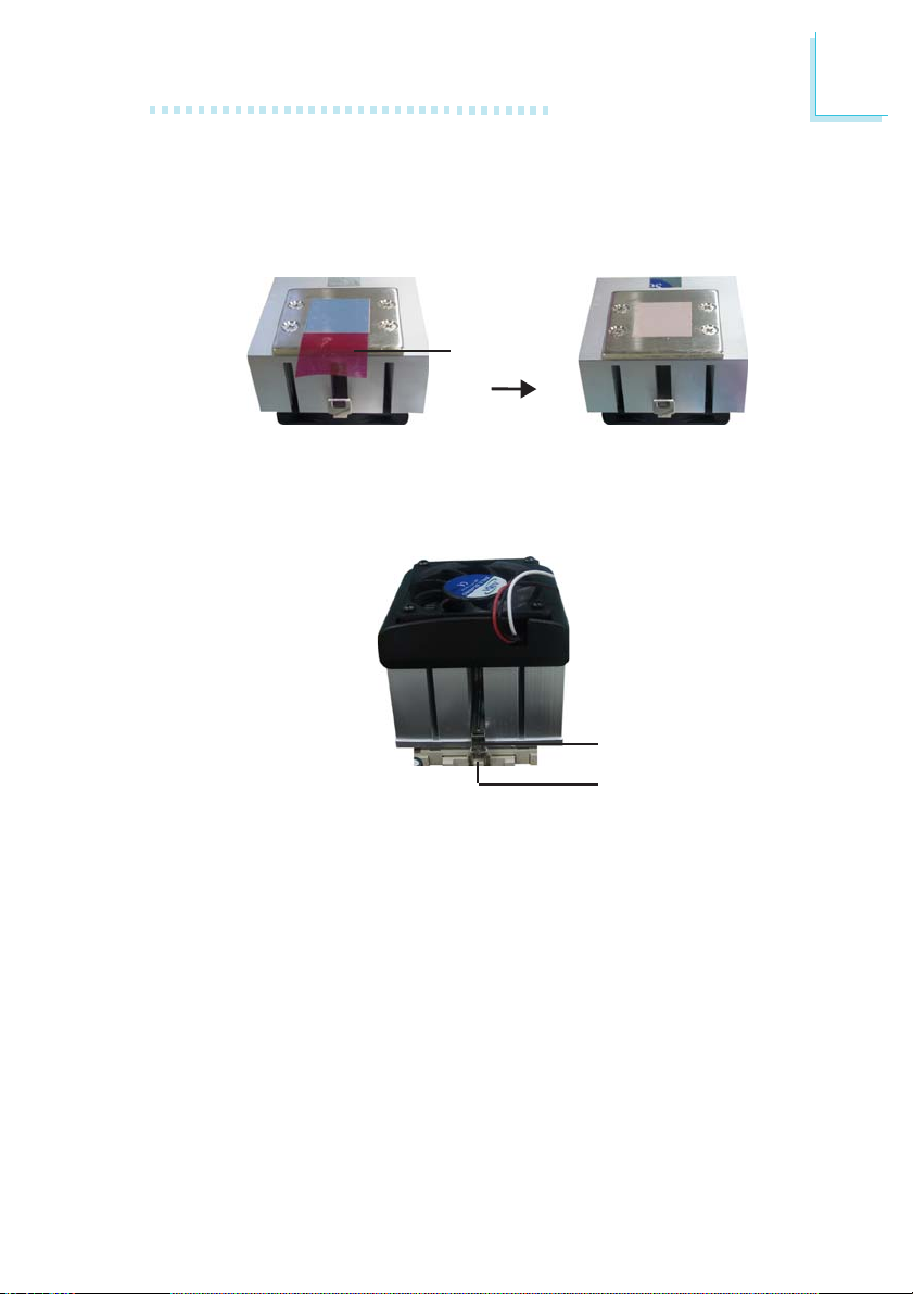
Do not apply the paste if the fan / heat sink already has a
patch of thermal paste on its underside. Peel the strip that
covers the paste then place the fan / heat sink on top of the
CPU.
Strip
2. After placing the fan / heat sink on top of the CPU, latch the
retaining clip on one side of the fan heat sink onto the protruding tab on the side of the socket.
2
Retaining clip
Ta b
3. Push down the other retaining clip until it latches and lock
onto the protruding tab on that side of the socket. Make sure
there is sufficient air circulation across the CPU fan and heat
sink.
4. Connect the CPU fan’s cable connector to the CPU fan connector on the system board.
23
2
Hardware Installation
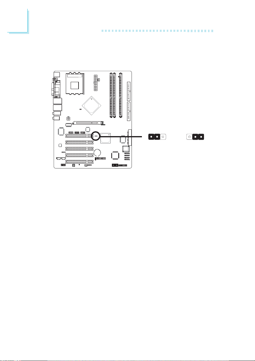
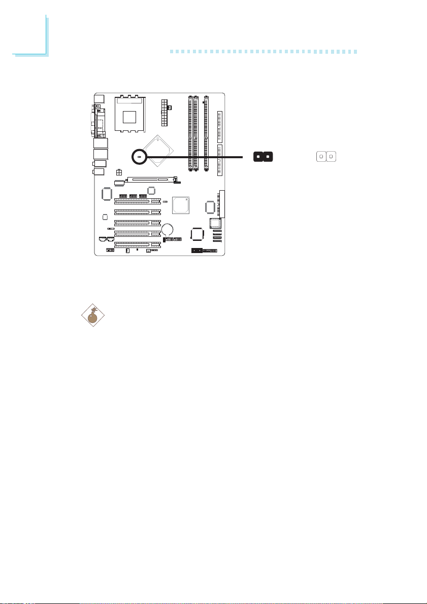
2.4 Jumper Settings
2.4.1 Jumper Settings for Clearing CMOS Data
JP1
X
1-2 On: Normal
(default)
If you encounter the following,
a) CMOS data becomes corrupted.
b) You forgot the keyboard, supervisor or user password.
c) You are unable to boot-up the computer system because the proc-
essor’s clock/ratio was incorrectly set in the BIOS.
you can reconfigure the system with the default values stored in
the ROM BIOS.
To load the default values stored in the ROM BIOS, please follow
the steps below.
1. Power-off the system and unplug the power cord.
2. Set JP1 pins 2 and 3 to On. Wait for a few seconds and set
JP1 back to its default setting, pins 1 and 2 On.
3. Plug the power cord and power-on the system.
If your reason for clearing the CMOS data is due to incorrect
setting of the processor’s clock/ratio in the BIOS, please proceed to step 4.
Clear CMOS Data
312312
2-3 On:
24

Hardware Installation
4. After powering-on the system, press <Del> to enter the main
menu of the BIOS.
5. Select the Genie BIOS Setting submenu and press <Enter>.
6. Set the “CPU Clock Setting” or “CPU Ratio” field to its default setting or an appropriate bus clock or frequency ratio.
Refer to the Genie BIOS Setting section in chapter 3 for
more information.
7. Press <Esc> to return to the main menu of the BIOS setup
utility. Select “Save & Exit Setup” and press <Enter>.
8. Type <Y> and press <Enter>.
2
25
2
Hardware Installation
2.4.2 Jumper Settings for Selecting the CPU’s FSB
21
J8
X
On: Other CPUs
(default)
21
Off: 100MHz
This jumper is used to select the front side bus of the CPU
installed on the system board.
.
.
.
.
.
.
Warning:
.
.
To ensure proper boot up and operation of your system, you
must power-off the system then turn off the power supply’s
switch or unplug the AC power cord prior to altering the setting
of the jumper.
26

2.5 Rear Panel I/O Ports
Hardware Installation
2
PS/2
Mouse
PS/2
K/B
The rear panel I/O ports consist of the following:
• PS/2 mouse port
• PS/2 keyboard port
• Parallel port
• COM port
• S/PDIF-in jack
• S/PDIF-out jack
• LAN ports
• USB ports
• Mic-in jack
• Line-in jack
• Line-out jack
• Center/Bass jack
• Rear out jack
Parallel
COM S/PDIF-in
S/PDIF-out
LAN 1
USB 1-2
LAN 2
USB 4
USB 3-4
Mic-in
Line-in
Center/Bass
Rear out
Line-out
27
2
Hardware Installation
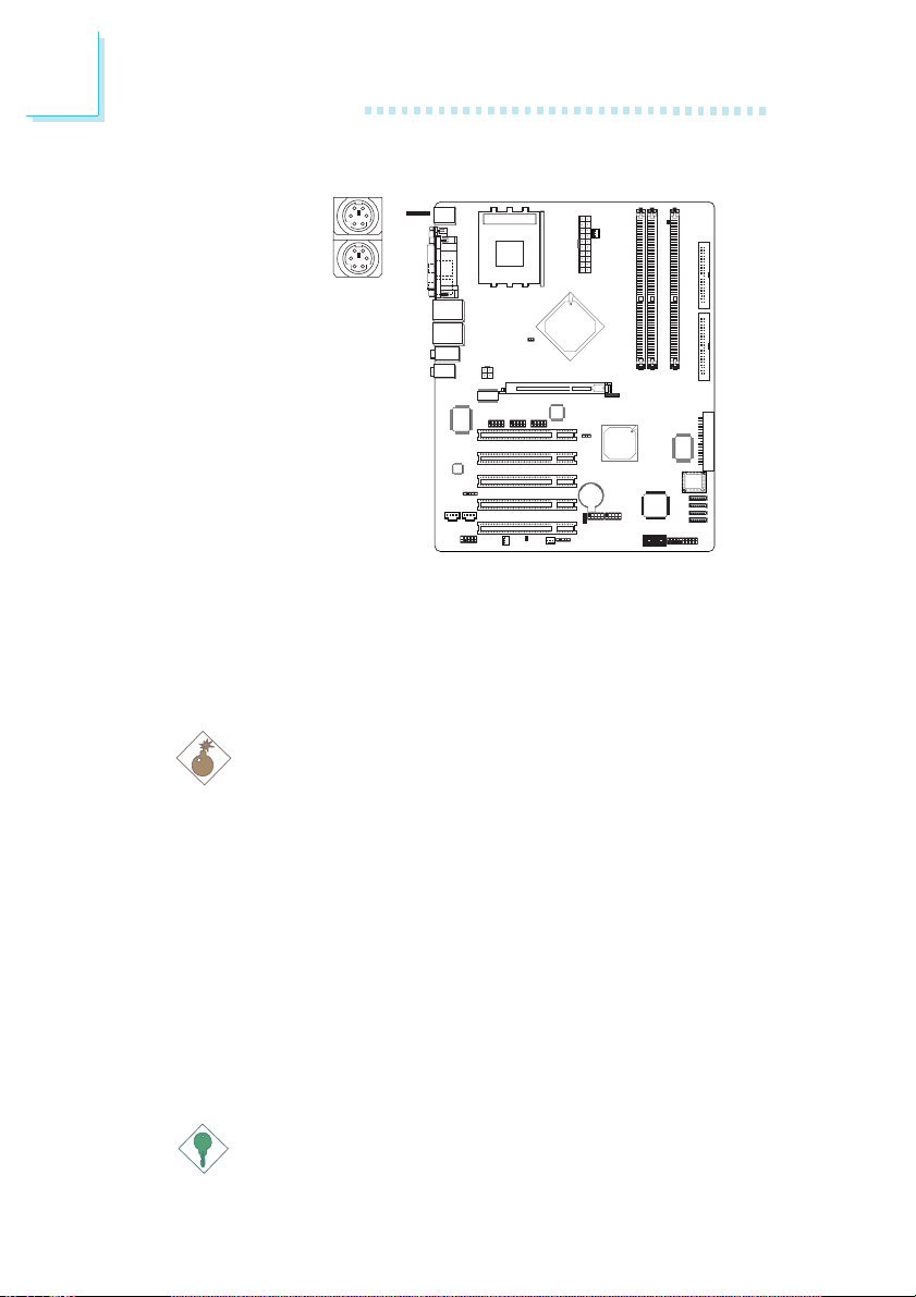
2.5.1 PS/2 Mouse and PS/2 Keyboard Ports
PS/2 Mouse
PS/2 Keyboard
W
The system board is equipped with an onboard PS/2 mouse
(Green) and PS/2 keyboard (Purple) ports - both at location
CN1 of the system board. The PS/2 mouse port uses IRQ12. If a
mouse is not connected to this port, the system will reserve
IRQ12 for other expansion cards.
.
.
.
.
.
Warning:
.
.
.
Make sure to turn off your computer prior to connecting or
disconnecting a mouse or keyboard. Failure to do so may damage the system board.
28
Wake-On-PS/2 Keyboard/Mouse
The Wake-On-PS/2 Keyboard/Mouse function allows you to use
the PS/2 keyboard or PS/2 mouse to power-on the system. To
use this function:
• BIOS Setting:
“Keyboard/Mouse Power On” in the Power Management
Setup submenu of the BIOS must be set accordingly. Refer to
chapter 3 for more information.
Important:
The 5VSB power source of your power supply must support
≥
720mA.
Hardware Installation
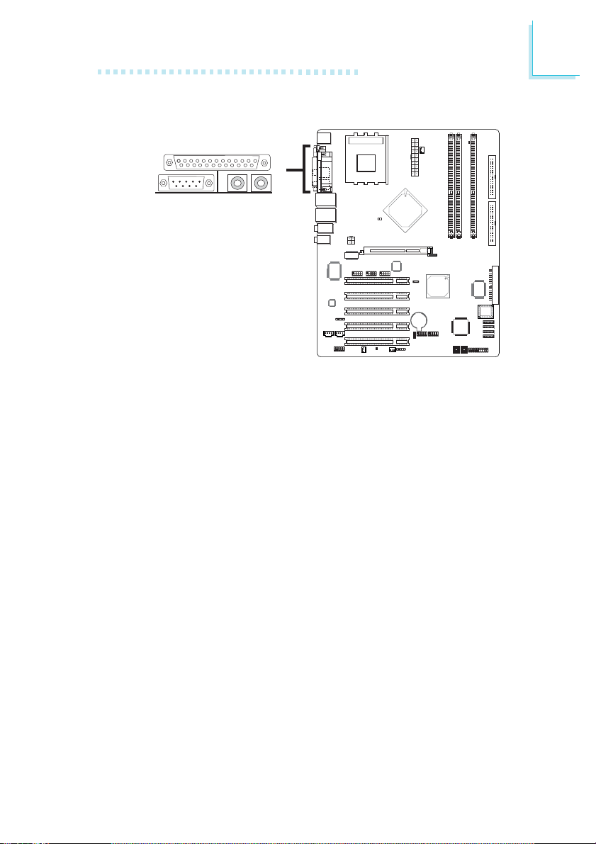
2.5.2 Serial Port
W
COM
The system board is equipped with an onboard serial port (Teal/
Turquoise) at location CN6 of the system board. It is a RS-232C
asynchronous communication port with 16C550A-compatible
UART that can be used with a modem, serial printer, remote
display terminal or other serial devices.
2
BIOS Setting
Select the serial port’s I/O address in the Integrated Peripherals
submenu (“Super IO Device” section) of the BIOS. Refer to
chapter 3 for more information.
29

2
Hardware Installation
2.5.3 Parallel Port
Parallel
W
The system board has a standard parallel port (Burgundy) at location CN9 for interfacing your PC to a parallel printer. It supports SPP, ECP and EPP.
30
Setting
SPP
(Standard Parallel Port)
ECP
(Extended Capabilities
Por t)
EPP
(Enhanced Parallel Port)
BIOS Setting
Select the parallel port’s mode in the Integrated Peripherals
submenu (“Super IO Device” section) of the BIOS. Refer to
chapter 3 for more information.
Allows normal speed operation
but in one direction only.
Allows parallel port to operate in
bidirectional mode and at a speed
faster than the SPP’s data transfer
rate.
Allows bidirectional parallel port
operation at maximum speed.
Function
 Loading...