

ISTRUZIONI PER L’INSTALLAZIONE, L’USO E LA MANUTENZIONE - IT
INSTRUCTIONS FOR INSTALLATION, USE AND MAINTENANCE - EN
ANWEISUNGEN FÜR DIE AUFSTELLUNG, DEN GEBRAUCH UND DIE WARTUNG - DE
INSTRUCTIONS POUR L’INSTALLATION, L’UTILISATION ET L’ENTRETIEN – FR
INSTRUCCIONES PARA LA INSTALACIÓN, EL USO Y EL MANTENIMIENTO - ES
TERMOCUCINOTTA EVO DSA - TERMOCUCINOTTA DSA
Testata secondo / Tested according to / Geprüft nach / Certié selon / Probado según : EN12815
IT – PER EVITARE DANNI ALL’APPARECCHIO, RISPETTARE IL CARICO ORARIO DI COMBUSTIBILE INDICATO
NEL PRESENTE LIBRETTO.
EN – TO AVOID DAMAGES TO THE APPLIANCE, PLEASE RESPECT THE MAX. FUEL QUANTITY (KG/HR)
INDICATED IN THE USER’S MANUAL.
DE – UM SCHÄDEN AN DEM GERÄT ZU VERMEIDEN, BITTE BEACHTEN SIE DIE BRENNSTOFFMENGE (KG/H)
LT. BEDIENUNGSANLEITUNG.
FR – POUR EVITER DES DOMMAGES A L’APPAREIL RESPECTER LA QUANTITE’ MAX. DE COMBUSTIBLE (KG/H)
COMME INDIQUE DANS LA NOTICE D’UTILISATION
ES – PARA EVITAR QUE EL APARATO SE DAÑE, RESPETE EL HORARIO DE LA CARGA DE COMBUSTIBLE
INDICADA EN EL MANUAL.
NORME DI SICUREZZA SUGLI APPARECCHI - Per il rispetto delle norme di sicurezza è obbligatorio installare e utilizzare i nostri
prodotti seguendo scrupolosamente le indicazioni fornite nel presente manuale.
SAFETY REGULATIONS ON THE APPLIANCES- To meet safety regulations, it is compulsory to install and use our products
carefully following the instructions contained in this manual.
SICHERHEITSVORSCHRIFTEN BEI DEN AUSRÜSTUNGEN - Um die Sicherheitsvorschriften zu beachten, ist es notwendig,
unsere Produkte vorsichtig nach den in diesem Handbuch enthaltenen Anweisungen zu installieren und anzuwenden.
RÉGLÉS DE SÉCURITÉ SUR LES APPAREILS - Selon les normes de sécurité sur les appareils l’acheteur et le commerçant sont
contraints de s’informer sur le fonctionnement correct sur la base des instructions d’emploi.
NORMAS DE SEGURIDAD DE LOS APARATOS - Según las normas de seguridad de los aparatos, el comprador y el comerciante
tienen la obligación de informarse sobre el correcto funcionamiento según las instrucciones de uso.

TERMOCUCINOTTA EVO DSA - TERMOCUCINOTTA DSA
ITALIANO ...................................................................................... 4
ENGLISH .................................................................................... 17
DEUTSCH ................................................................................... 30
FRANÇAIS .................................................................................. 43
ESPAÑOL ................................................................................... 56
2 7093041
TERMOCUCINOTTA EVO DSA - TERMOCUCINOTTA DSA
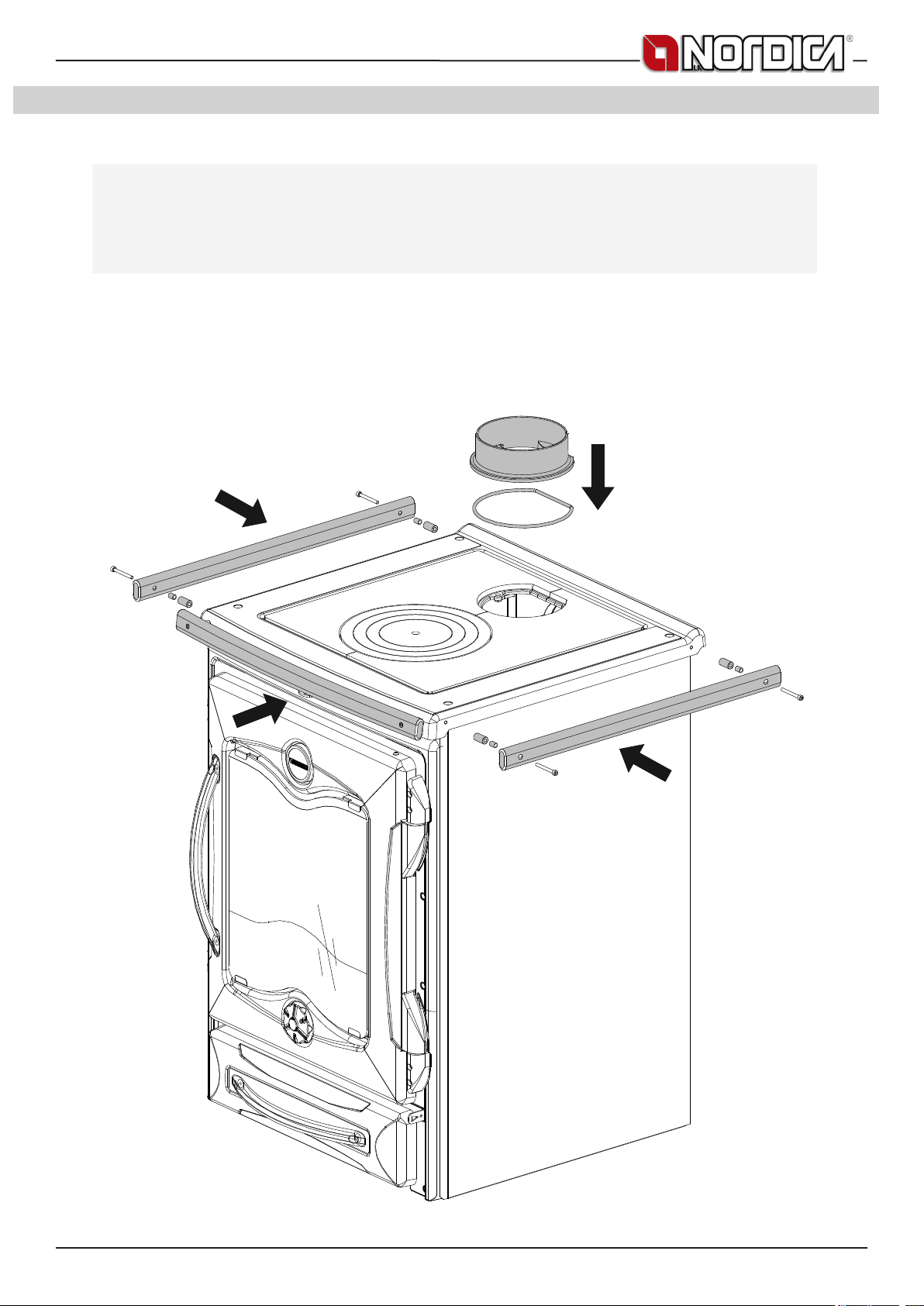
1. INSTALLAZIONE
PRIMA DELL’INSTALLAZIONE ESEGUIRE LE SEGUENTI VERIFICHE.
BEFORE THE INSTALLATION PERFORM THE FOLLOWING CHECKS.
AVANT L’INSTALLATION IL FAUT RÉALISER LES SUIVANTES VÉRIFICATIONS
.ANTES DE LA INSTALACIÓN, REALIZAR LOS CONTROLES SIGUIENTES
1. INSTALLATION
1. INSTALLATION
1. L’INSTALLATION
1. LA INSTALACIÓN
VOR DER AUFSTELLUNG FOLGENDE PRÜFUNGEN AUSFÜHREN.
7093041 3
TERMOCUCINOTTA EVO DSA - TERMOCUCINOTTA DSA
INFORMAZIONI ALL’UTENTE SULLO SMALTIMENTO DELLE APPARECCHIATURE DA PARTE DEI PRIVATI
NEL TERRITORIO DELL’UNIONE EUROPEA
Ai sensi dell’art.13 del decreto legislativo 25 luglio 2005, n.151 «attuazione delle direttive 2011/65/CE e 2003/1 08/CE, relative
sostanze alla riduzione dell’uso di sostanze pericolose nelle apparecchiature elettriche ed elettroniche, nonché allo smaltimento dei
riuti». il simbolo del cassonetto barrato riportato sull’apparecchiatura o sulla confezione indica che il prodotto alla ne della propria
vita utile deve essere raccolto separatamente dagli altri riuti. L’utente dovrà, pertanto, conferire l’apparecchiatura giunta a ne vita agli
idonei centri di raccolta differenziata dei riuti elettronici ed elettrotecnici, oppure riconsegnarla al rivenditore al momento dell’acquisto
di una nuova apparecchiatura di tipo equivalente, in ragione di uno a uno. L’adeguata raccolta differenziata per l’awio successivo
dell’apparecchiatura e dismessa al riciclaggio, al trattamento e allo smaltimento ambientalmente compatibile, contribuisce ad evitare
possibili effetti negativi sull’ambiente e sulla salute e favorisca il reimpiego e/o riciclo dei materiali di cui è composta l’apparecchiatura.
Lo smaltimento abusivo del prodotto da parte dell’utente comporta l’applicazione delle sanzioni amministrative previste dalla normativa
vigente, di cui al digs n. 22/1997 (articolo 50 e seguenti del digs n. 22/1997).
DICHIARAZIONE DI CONFORMITA’ DEL COSTRUTTORE
Oggetto: Assenza di amianto e cadmio
Si dichiara che tutti i nostri apparecchi vengono assemblati con materiali che non presentano parti di amianto o suoi
derivati e che nel materiale d’apporto utilizzato per le saldature non è presente/utilizzato in nessuna forma il cadmio, come
previsto dalla norma di riferimento.
Oggetto: Regolamento CE n. 1935/2004
Si dichiara che in tutti gli apparecchi da noi prodotti, i materiali destinati a venire a contatto con i cibi sono adatti all’uso
alimentari, in conformità al Regolamento CE in oggetto.
ITALIANO - INDICE
1. INSTALLAZIONE ............................................................................................................................................................................. 3
2. DATI TECNICI .................................................................................................................................................................................. 5
3. AVVERTENZE GENERALI ............................................................................................................................................................. 5
4. NORME PER L’INSTALLAZIONE ................................................................................................................................................... 5
4.1. Vaso di espansione APERTO..........................................................................................................................................................................6
4.2. Vaso di espansione CHIUSO ..........................................................................................................................................................................7
4.3. VALVOLA MISCELATRICE ANTICONDENSA - OBBLIGATORIO (fornita come OPTIONAL) .......................................................................7
4.4. VAST - VALVOLA AUTOMATICA SCARICO TERMICO DSA (fornita come OPTIONAL) ...............................................................................7
4.5. COLLEGAMENTO E CARICO DELL’IMPIANTO ............................................................................................................................................7
5. SICUREZZA ANTINCENDIO ...........................................................................................................................................................8
5.1. PRONTO INTERVENTO .................................................................................................................................................................................8
6. DESCRIZIONE TECNICA ................................................................................................................................................................8
7. CANNA FUMARIA ...........................................................................................................................................................................9
7.1. COMIGNOLO ..................................................................................................................................................................................................9
7.2. COLLEGAMENTO AL CAMINO ......................................................................................................................................................................9
7.3. COLLEGAMENTO ALLA CANNA FUMARIA DI UN CAMINETTO O FOCOLARE APERTO .......................................................................10
8. AFFLUSSO D’ARIA NEL LUOGO D’INSTALLAZIONE DURANTE LA COMBUSTIONE ...........................................................10
9. COMBUSTIBILI AMMESSI / NON AMMESSI ...............................................................................................................................10
10. ACCENSIONE ...............................................................................................................................................................................11
10.1. ACCENSIONE a BASSE EMISSIONI ...........................................................................................................................................................12
11. FUNZIONAMENTO NORMALE ....................................................................................................................................................12
11.1. USO DEL FORNO (dove presente) ..............................................................................................................................................................12
11.2. MANCANZA DI ENERGIA ELETTRICA ........................................................................................................................................................13
11.3. FUNZIONAMENTO NEI PERIODI DI TRANSIZIONE .................................................................................................................................. 13
11.4. UTILIZZO ESTIVO DEL PRODOTTO. ..........................................................................................................................................................13
12. MANUTENZIONE E CURA ............................................................................................................................................................13
12.1. PULIZIA VETRO ...........................................................................................................................................................................................13
12.2. PULIZIA CASSETTO CENERE ....................................................................................................................................................................13
12.3. PULIZIA CANNA FUMARIA ..........................................................................................................................................................................14
12.4. FERMO ESTIVO ...........................................................................................................................................................................................14
12.5. LE MAIOLICHE (dove presente) ...................................................................................................................................................................14
12.6. PRODOTTI IN PIETRA OLLARE (dove presente) ........................................................................................................................................14
12.7. PRODOTTI VERNICIATI (dove presente) ....................................................................................................................................................14
12.8. PRODOTTI SMALTATI (dove presente) ........................................................................................................................................................14
12.9. COMPONENTI CROMATI (dove presente) ..................................................................................................................................................14
12.10. CERCHI in ghisa ...........................................................................................................................................................................................14
12.11. CORRIMANO LATERALI (dove presente) ...................................................................................................................................................14
12.12. PULIZIA GRIGLIA FOCOLARE.....................................................................................................................................................................14
12.13. MANUTENZIONE DELL’IMPIANTO IDRAULICO .........................................................................................................................................15
13. DETERMINAZIONE DELLA POTENZA TERMICA ....................................................................................................................... 15
14. CONDIZIONI DI GARANZIA ..........................................................................................................................................................15
15. SCHEMA DI INSTALLAZIONE ......................................................................................................................................................69
15.1. SCHEDA TECNICA valvola termostatica VAST ............................................................................................................................................74
16. DIMENSIONI ..................................................................................................................................................................................80
4 7093041
TERMOCUCINOTTA EVO DSA - TERMOCUCINOTTA DSA
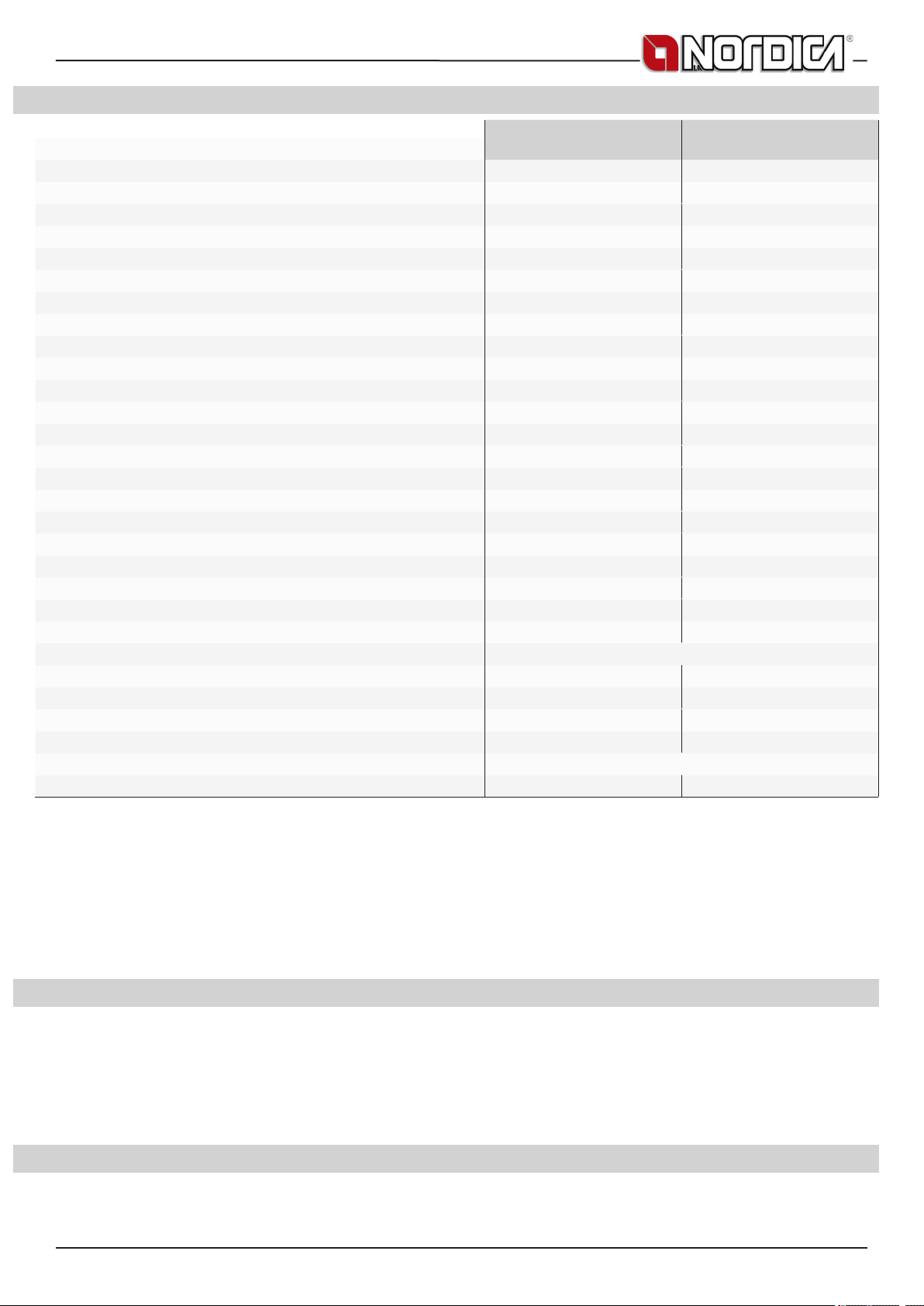
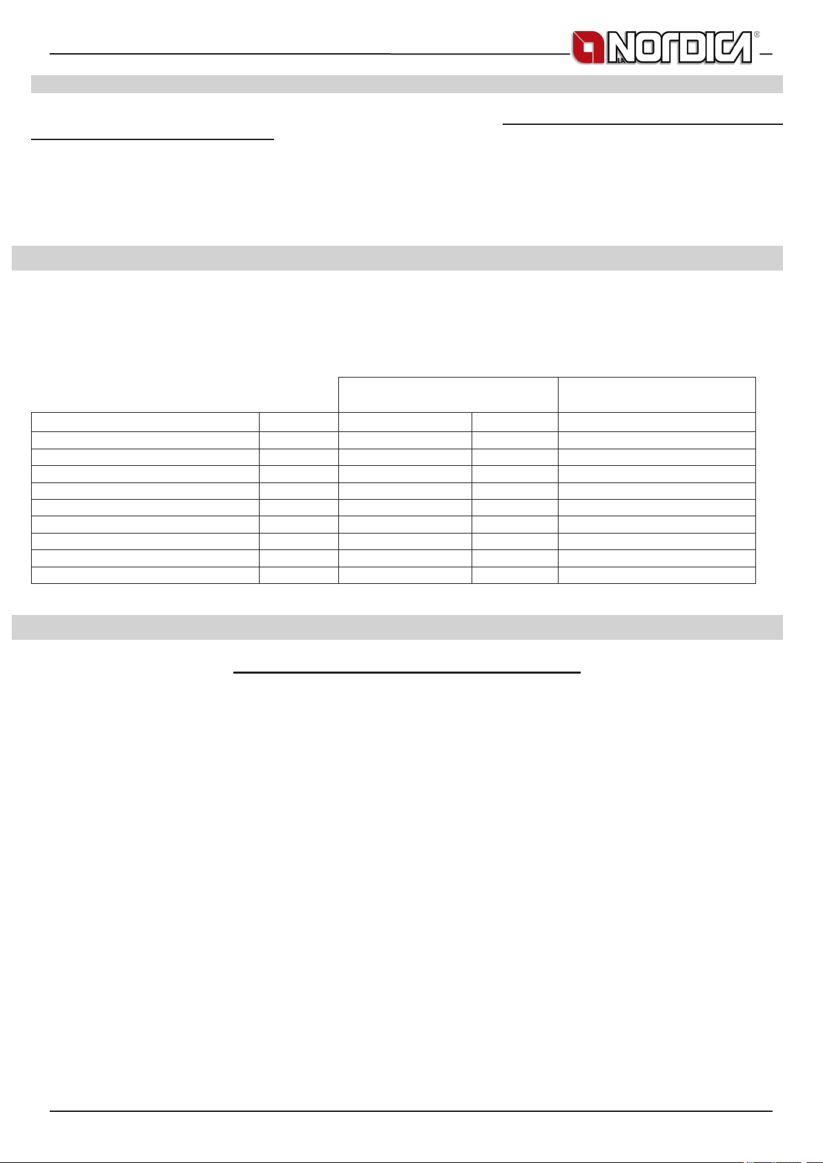
2. DATI TECNICI
Denizione termoprodotto secondo EN 13240
Sistema costruttivo
Potenza termica globale in kW
Potenza termica nominale (utile) in kW
Potenza resa al liquido (H2O) in kW
Potenza resa all’ambiente in kW
Consumo orario legna in kg/h (legna con 20% umidità)
Rendimento in %
CO misurato al 13% di ossigeno in %
Diametro scarico fumi in mm
Canna fumaria altezza - dimensioni in mm (#)
Contenuto uido scambiatore (H2O) in L (litri)
Depressione al camino (tiraggio) in Pa (mm H2O)
Allacciamento caldaia (Ø)
Tubo scarico automatico (Ø)
Presa aria esterna (Ø) in mm (superce minima cm2)
Emissione gas di scarico in g/s – legna
Temperatura gas di scarico nel mezzo in °C - legna
Temperatura ottimale di esercizio in °C
Pressione max d’esercizio in bar (vaso espansione Aperto - Chiuso)
Dimensioni bocca fuoco in mm (L x H)
Dimensioni focolare in mm (L x H x P)
Dimensioni forno in mm (L x H x P)
TERMOCUCINOTTA EVO
1 1
21,4 30,5
16,9 22,6
11,9 15,7
5 6,9
4,9 6,8
78,8 74
0,09 (1152 mg/Nm
150 150
5m – 220x220 Ø220 5m – 220x220 Ø220
20,5 20,5
17 - 20 (1,7 - 2,0) 17 - 20 (1,7 - 2,0)
1 ”F gas 1 ”F gas
3/4”M gas 3/4”M gas
150 (100 cm2) 150 (100 cm2)
14,7 21,7
297 325
70 - 75 70 - 75
VEA 1,5 bar - VEC 3 bar VEA 1,5 bar - VEC 3 bar
405 x 260 405 x 260
415 x 275 x 475 415 x 275 x 475
/ /
3
) 0,32 (3996 mg/Nm3)
TERMOCUCINOTTA DSA
Tipo di griglia Movibile - piana
Altezza in mm
Larghezza in mm
Profondità in mm
Peso in Kg
860 860
682 682
679 679
205 205
Distanze di sicurezza antincendio Capitolo SICUREZZA
m3 riscaldabili (30 kcal/h x m3) (# #)
484 650
(#) Diametro 200 mm utilizzabile con canna fumaria non inferiore a 6 m.
(# #) Per edifici il cui isolamento termico non corrisponde alle disposizioni sulla protezione del calore, il volume di riscaldamento è: tipo
di costruzione favorevole (30 Kcal/h x m3); tipo di costruzione meno favorevole (40 Kcal/h x m3); tipo di costruzione sfavorevole (50
Kcal/h x m3).
Con un isolamento termico secondo le norme sul risparmio energetico il volume riscaldato è maggiore. Con un riscaldamento temporaneo,
in caso di interruzioni superiori a 8h, la capacità di riscaldamento diminuisce del 25% circa.
IMPORTANTE: La potenza dell’impianto termico collegato, deve essere commisurata alla potenza ceduta all’acqua dal termoprodotto;
un carico troppo ridotto non consente un regolare funzionamento del forno, mentre un carico troppo elevato impedisce un adeguato
riscaldamento dei radiatori.
3. AVVERTENZE GENERALI
La responsabilità de La NORDICA S.p.A. è limitata alla fornitura dell’apparecchio.
Il suo impianto va realizzato in modo conforme alla regola dell’arte, secondo le prescrizioni delle presenti istruzioni e le regole della
professione, da personale qualicato, che agisce a nome di imprese adatte ad assumere l’intera responsabilità dell’insieme dell’impianto.
La NORDICA S.p.A. non è responsabile del prodotto modicato senza autorizzazione e tanto meno per l’uso di ricambi non
originali. NON SI POSSONO EFFETTUARE MODIFICHE ALL’APPARECCHIO. Non vi sarà responsabilità da parte di La NORDICA
S.p.A. in caso di mancato rispetto di tali precauzioni.
E’ OBBLIGATORIO rispettare norme nazionali ed europee, disposizioni locali o in materia edilizia, nonché regolamentazioni
antincendio.
4. NORME PER L’INSTALLAZIONE
L’installazione del prodotto e degli equipaggiamenti ausiliari, relativi all’impianto di riscaldamento, deve essere conforme a tutte le Norme
e Regolamentazioni attuali ed a quanto previsto dalla Legge.
L’installazione, i relativi collegamenti dell’impianto, la messa in servizio e la verica del corretto funzionamento devono essere eseguiti
7093041 5
TERMOCUCINOTTA EVO DSA - TERMOCUCINOTTA DSA
a regola d’arte da personale professionalmente preparato nel pieno rispetto delle norme vigenti, sia nazionali, regionali, provinciali e
comunali presenti nel paese in cui è stato installato l’apparecchio, nonché delle presenti istruzioni.
L’installazione deve essere eseguita da personale autorizzato, che dovrà rilasciare all’acquirente una dichiarazione di conformità
dell’impianto, il quale si assumerà l’intera responsabilità dell’installazione denitiva e del conseguente buon funzionamento del prodotto
installato. Prima dell’installazione eseguire le seguenti veriche:
• Accertarsi che il pavimento possa sostenere il peso dell’apparecchio e provvedere ad un adeguato isolamento nel caso sia costruito in
materiale inammabile (DIMENSIONI SECONDO L’ORDINAMENTO REGIONALE).
• Assicurarsi che nella stanza dove sarà installato vi sia una ventilazione adeguata, a tale proposito è fondamentale prestare attenzione
a nestre e porte con chiusura stagna (guarnizioni di tenuta)
• Evitare l’installazione in locali con presenza di condotti di ventilazione collettivo, cappe con o senza estrattore, apparecchi a gas di tipo
B, pompe di calore o la presenza di apparecchi il cui funzionamento contemporaneo possa mettere in depressione il locale (rif. Norma
UNI 10683)
• Accertarsi che la canna fumaria e i tubi a cui verrà collegato l’apparecchio siano idonei, Non è consentito il collegamento di più
apparecchi allo stesso camino.
• Il diametro dell’apertura per il collegamento al camino deve corrispondere per lo meno al diametro del tubo fumo. L’apertura dovrebbe
essere dotata di una connessione a muro per l’inserimento del tubo di scarico e di un rosone.
• L’installazione deve prevedere l’accesso alle operazioni di pulizia e manutenzione del prodotto e della canna fumaria.
Prima dell’installazione, si consiglia di effettuare un lavaggio accurato di tutte le tubazioni dell’impianto onde rimuovere eventuali residui
che potrebbero compromettere il buon funzionamento del termoprodotto.
IMPORTANTE:
a) E’ opportuno installare una valvola di sato (manuale o automatica) per permettere di togliere aria dall’impianto.
b) In caso di fuoriuscite d’acqua chiudere l’alimentazione idrica ed avvisare con sollecitudine il servizio tecnico di assistenza;
c) La pressione di esercizio dell’impianto deve essere periodicamente controllata.
d) In caso di non utilizzo della caldaia per un lungo periodo è consigliabile l’intervento del servizio tecnico di assistenza per effettuare
almeno le seguenti operazioni: - chiudere i rubinetti dell’acqua sia dell’impianto termico sia del sanitario; - svuotare l’impianto termico
e sanitario se c’è rischio di gelo.
I termoprodotti modello DSA possono essere installati sia in un impianto a VASO di espansione APERTO (cap.4.1) sia in un impianto a
VASO di espansione CHIUSO (cap.4.2).
La NORDICA S.p.A. declina ogni responsabilità per danni a cose e/o persone provocati dall’impianto. Inoltre non è responsabile
del prodotto modicato senza autorizzazione e tanto meno per l’uso di ricambi non originali. Il Vostro abituale spazzacamino di
zona deve essere informato sull’installazione del prodotto, afnché possa vericarne il regolare collegamento alla canna fumaria ed il
grado di efcienza di quest’ultima.
4.1. Vaso di espansione APERTO
L’impianto con vaso di espansione aperto, deve essere OBBLIGATORIAMENTE provvisto di:
1. VASO DI ESPANSIONE APERTO: vaso avente una capacità pari al 10 % del contenuto d’acqua totale del termoprodotto e dell’impianto.
Il vaso va posizionato nel punto più alto dell’impianto almeno 2 m sopra il radiatore posto al livello più alto.
2. TUBO DI SICUREZZA : tubo che collega per la via più breve, senza tratti discendenti o sifonanti, la mandata del termoprodotto con la
parte superiore del vaso di espansione aperto. ATTENZIONE : il diametro interno del tubo di mandata che collega il termoprodotto al
vaso di espansione aperto deve essere uguale al diametro interno del connettore di mandata presente nel termo prodotto. Il suddetto
tubo di collegamento deve essere privo d’intercettazioni.
3. TUBO DI CARICO : tubo che collega il fondo del vaso di espansione aperto con il tubo di ritorno dell’impianto. La sezione minima
deve essere di ¾”gas. Tutti questi elementi non devono per nessuna ragione avere organi di intercettazione interposti che possano
accidentalmente escluderli e devono essere posizionati in ambienti non esposti al gelo poiché, se dovessero gelare, si potrebbe
vericare la rottura o addirittura l’esplosione del corpo caldaia. In caso di esposizione al gelo sarà opportuno aggiungere all’acqua
dell’impianto una adeguata percentuale di liquido antigelo che consentirà di eliminare completamente il problema. In nessun modo ci
dovrà essere circolazione d’acqua nel vaso di espansione aperto fra il tubo di sicurezza ed il tubo di carico. Questa provocherebbe
l’ossigenazione dell’acqua e la conseguente corrosione del termoprodotto e dell’impianto in tempi molto brevi
4. VALVOLA AUTOMATICA DI SCARICO TERMICO DSA: costituisce una ulteriore sicurezza positiva in grado di prevenire l’ebollizione
anche in assenza di energia elettrica. E’ costituita da un corpo valvola simile ad una valvola di sicurezza a pressione che, a differenza
di questa, si apre al raggiungimento di una temperatura pretarata ( di solito 94 – 95° C ) scaricando dalla mandata dell’impianto acqua
calda che verrà sostituita con altrettanta acqua fredda proveniente attraverso il tubo di carico del vaso di espansione aperto smaltendo
in questo modo il calore eccessivo.
5. VALVOLA DI SICUREZZA da 1,5 bar: la massima pressione di esercizio ammessa per l’impianto è di 1,5 bar (pari a 15 m di colonna
d’acqua), pressioni superiori possono provocare deformazioni e rotture al corpo caldaia.
6. ALTRI DISPOSITIVI di sicurezza previsti dalla Normativa vigente in materia.
7. POMPA DI CIRCOLAZIONE : deve essere preferibilmente montata sul ritorno per evitare che possa disinnescarsi a temperature
dell’acqua molto elevate, accertarsi però che non faccia circolare l’acqua nel vaso di espansione aperto altrimenti provocherebbe una
continua ossigenazione dell’acqua con conseguente, rapida, corrosione del corpo caldaia. La sua prevalenza deve essere tale da non
provocare una circolazione forzata nel vaso di espansione aperto. Deve inoltre essere collegata ad un termostato o alla centralina
elettronica fornita come OPTIONAL.
8. VALVOLA MISCELATRICE ANTICONDENSA – (vedi capitolo 4.3)
ATTENZIONE: i sensori di sicurezza della temperatura devono essere installati a bordo macchina o ad una distanza non maggiore di
30 cm dal collegamento di mandata del termoprodotto. Qualora i termoprodotti non siano provvisti di tutti i dispostivi, quelli mancanti
possono essere installati sulla tubazione di mandata del termoprodotto entro una distanza dal termoprodotto non maggiore di 1
m. Tutti questi elementi non devono per nessuna ragione avere organi di intercettazione interposti che possano accidentalmente
6 7093041

TERMOCUCINOTTA EVO DSA - TERMOCUCINOTTA DSA
escluderli e devono essere posizionati in ambienti non esposti al gelo poiché, se dovessero gelare, si potrebbe vericare la rottura o
addirittura l’esplosione del corpo caldaia.
ATTENZIONE: Per nessuna ragione si deve accendere il fuoco se prima l’impianto non sia stato completamente riempito d’acqua;
il farlo comporterebbe un danneggiamento gravissimo di tutta la struttura. Il riempimento dell’impianto deve essere fatto tramite
il tubo di carico direttamente nella vaschetta del vaso di espansione aperto in modo da evitare che una eccessiva pressione della rete
idrica deformi il corpo caldaia.
L’impianto va tenuto costantemente pieno d’acqua anche nei periodi in cui non è richiesto l’uso. Durante il periodo invernale un’eventuale
non attività va affrontata con l’aggiunta di sostanze antigelo.
4.2. Vaso di espansione CHIUSO
L’impianto con vaso di espansione CHIUSO, deve essere OBBLIGATORIAMENTE provvisto di:
1. VALVOLA DI SICUREZZA - la massima pressione di esercizio ammessa per l’impianto è di: Vedi DICHIARAZIONE DI PRESTAZIONE
- INFORMAZIONI MARCATURA CE, pressioni superiori possono provocare deformazioni e rotture del corpo caldaia. ATTENZIONE : il
diametro interno del tubo di mandata che collega il termoprodotto alla valvola di sicurezza deve essere uguale al diametro interno del
connettore di mandata presente nel termo prodotto. Il suddetto tubo di collegamento deve essere privo d’intercettazioni.
2. VALVOLA MISCELATRICE ANTICONDENSA – (vedi capitolo 4.3)
3. VALVOLA AUTOMATICA DI SCARICO TERMICO DSA o VALVOLA DI SCARICO DI SICUREZZA TERMICA, con sensore a doppia
sicurezza
4. VASO DI ESPANSIONE CHIUSO collegato sul ritorno del termoprodotto. ATTENZIONE: il diametro interno del tubo di ritorno che
collega il termoprodotto al vaso di espansione chiuso deve essere uguale al diametro interno del connettore di ritorno presente nel
termo prodotto. Il suddetto tubo di collegamento deve essere privo d’intercettazioni.
5. TERMOSTATO DI COMANDO DEL CIRCOLATORE
6. TERMOSTATO DI ATTIVAZIONE DELL’ALLARME ACUSTICO
7. ALLARME ACUSTICO
8. INDICATORE DI TEMPERATURA
9. INDICATORE DI PRESSIONE
10. SISTEMA DI CIRCOLAZIONE
ATTENZIONE: i sensori di sicurezza della temperatura devono essere installati a bordo macchina come indicato al capitolo 4.1. Tutti
questi elementi non devono per nessuna ragione avere organi di intercettazione interposti che possano accidentalmente escluderli e
devono essere posizionati in ambienti non esposti al gelo poiché, se dovessero gelare, si potrebbe vericare la rottura o addirittura
l’esplosione del corpo caldaia.
OBBLIGATORIAMENTE i termoprodotti per il riscaldamento di tipo domestico inseriti in impianti di riscaldamento a VASO CHIUSO
devono essere dotati, al loro interno, di un circuito di raffreddamento predisposto dal costruttore dell’apparecchio, attivato da una valvola
di sicurezza termica (vedi capitolo 4.4) che non richieda energia ausiliaria e tale da garantire che non venga superata la temperatura
limite imposta dalla norma. Il collegamento tra il gruppo di alimentazione e la valvola deve essere privo di intercettazioni. La pressione a
monte del circuito di raffreddamento deve essere di almeno 1,5 bar.
4.3. VALVOLA MISCELATRICE ANTICONDENSA - OBBLIGATORIO (fornita come OPTIONAL)
La valvola miscelatrice anticondensa trova applicazione nei termoprodotti a combustibile solido in quanto previene il ritorno di acqua fredda
nello scambiatore Figura 1 a pagina 73. Le tratte 1 e 3 sono sempre aperte e, assieme alla pompa installata sul ritorno (R), garantiscono
la circolazione dell’acqua all’interno dello scambiatore della caldaia a biomassa (CB). Una elevata temperatura di ritorno permette di
migliorare l’efcienza, riduce la formazione di condensa dei fumi e allunga la vita della caldaia. Le valvole in commercio presentano svariate
tarature, La NORDICA consiglia l’utilizzo del modello 55°C con connessioni idrauliche da 1”. Una volta raggiunta la temperatura di
taratura della valvola, viene aperta la tratta 2 e l’acqua della caldaia va all’impianto attraverso la mandata (M). IMPORTANTE la mancata
installazione del dispositivo fa decadere la garanzia dello scambiatore di calore.
4.4. VAST - VALVOLA AUTOMATICA SCARICO TERMICO DSA (fornita come OPTIONAL)
I termoprodotti a combustibile solido devono essere installati con le sicurezze previste dalle vigenti leggi in materia. A tale scopo la
termostufa è munita di uno serpentino di scarico termico.
Il serpentino di scarico termico dovrà essere collegato da un lato alla rete idrica (Figura 1 a pagina 73 / Cap. DIMENSIONI - pos. A) e dall’altro
alla rete di drenaggio (C). La valvola automatica di scarico termico DSA, il cui bulbo andrà collegato all’attacco B, al raggiungimento della
temperatura di sicurezza abilita l’ingresso di acqua fredda nel serpentino contenuto nella caldaia, scaricando l’eccesso termico tramite il
tubo C verso uno scarico opportunamente installato. La pressione a monte del circuito di raffreddamento deve essere di almeno 1,5 bar.
AVVERTENZA: Non potremo essere ritenuti responsabili per un cattivo funzionamento dell’impianto non conforme alle
prescrizioni delle presenti istruzioni o ancora dall’uso di prodotti complementari non adatti (vedi cap. SCHEDA TECNICA
valvola termostatica VAST).
4.5. COLLEGAMENTO E CARICO DELL’IMPIANTO
Alcuni esempi, puramente indicativi dell’impianto, sono riportati al capitolo SCHEMA DI INSTALLAZIONE, mentre i collegamenti al
termoprodotto sono riportati al capitolo DIMENSIONI.
ATTENZIONE :Il riempimento dell’impianto deve avvenire esclusivamente per caduta naturale dell’acqua dal vaso di espansione
aperto attraverso il tubo di carico per evitare che una pressione di rete troppo elevata dell’acquedotto possa deformare o far
scoppiare il corpo caldaia.
Durante questa fase aprire tutti gli sati dei termosifoni per evitare formazioni di sacche d’aria, sorvegliando poi la fuori uscita d’acqua per
evitare spiacevoli allagamenti.
Il collaudo di tenuta dell’impianto va eseguito con la pressione del vaso di espansione aperto.
L’impianto va tenuto costantemente pieno d’acqua anche nei periodi in cui non è richiesto l’uso del termoprodotto. Durante il
periodo invernale un’eventuale non attività va affrontata con l’aggiunta di sostanze antigelo.
7093041 7
TERMOCUCINOTTA EVO DSA - TERMOCUCINOTTA DSA
5. SICUREZZA ANTINCENDIO
Nell’installazione del prodotto devono essere osservate le seguenti misure di sicurezza:
a) Al ne di assicurare un sufciente isolamento termico, rispettare la distanza minima di sicurezza dal retro e da entrambi i lati da
elementi costruttivi ed oggetti inammabili e sensibili al calore (mobili, rivestimenti di legno, stoffe ecc.) (vedi Figura 5 a pagina 78 - A).
Tutte le distanze minime di sicurezza sono indicate sulla targhetta tecnica del prodotto e NON si deve scendere al di sotto
dei valori indicati;
b) Davanti alla porta del focolare, nell’area di radiazione della stessa non deve esserci alcun oggetto o materiale di costruzione inammabile
e sensibile al calore a meno di 100 cm di distanza. Tale distanza può essere ridotta a 40 cm qualora venga installata una protezione,
retroventilata e resistente al calore, davanti all’intero componente da proteggere;
c) Qualora il prodotto sia installato su un pavimento di materiale inammabile, bisogna prevedere un sottofondo ignifugo. I pavimenti in
materiale inammabile, come moquette, parquet o sughero etc., devono essere coperti da uno strato di materiale non inammabile,
ad esempio ceramica, pietra, vetro o acciaio etc. (dimensioni secondo l’ordinamento regionale). Il sottofondo deve sporgere frontalmente
di almeno 50 cm e lateralmente di almeno altri 30 cm rispetto l’apertura della porta di carico (vedi Figura 5 a pagina 78 - B);
d) Sopra al prodotto non devono essere presenti componenti inammabili (es. mobili - pensili).
Il prodotto deve funzionare esclusivamente con il cassetto cenere inserito. I residui solidi della combustione (ceneri) devono essere raccolti
in un contenitore ermetico e resistente al fuoco. Il prodotto non deve mai essere acceso in presenza di emissioni gassose o vapori (per
esempio colla per Linoleum, benzina ecc.). Non depositate materiali inammabili nelle vicinanze del prodotto .
Durante la combustione viene sprigionata energia termica che comporta un marcato riscaldamento delle superci, di porte, maniglie,
comandi, vetri, tubo fumi ed eventualmente della parte anteriore dell’apparecchio. Evitate il contatto con tali elementi senza un
corrispondente abbigliamento protettivo o senza utensili accessori (guanti resistenti al calore, dispositivi di comando).
Fate in modo che i bambini siano consapevoli di questi pericoli e teneteli lontani dal focolare durante il suo funzionamento.
Quando si utilizza un combustibile errato o troppo umido si formano dei depositi di catrame(creosoto) nella canna fumaria con il rischio
d’incendio.
5.1. PRONTO INTERVENTO
Se si manifesta un incendio nel collegamento o nella canna fumaria :
a) Chiudere la porta di caricamento e del cassetto cenere.
b) Chiudere i registri dell’aria comburente
c) Spegnere tramite l’uso di estintori ad anidride carbonica ( CO2 a polveri )
d) Richiedere l’immediato intervento dei Vigili del Fuoco
NON SPEGNERE IL FUOCO CON L’USO DI GETTI D’ACQUA.
Quando la canna fumaria smette di bruciare bisogna farla vericare da uno specialista per individuare eventuali crepe o punti permeabili.
6. DESCRIZIONE TECNICA
I termoprodotti La Nordica sono ideali per appartamenti di vacanza e case del ne settimana oppure come riscaldamento ausiliario durante
tutto l’anno. Come combustibili vengono utilizzati ceppi di legna. Questo è un apparecchio a combustione intermittente.
La termocucina è costituita di lastre in lamiera d’acciaio zincata, ghisa smaltata. Il focolare si trova all’interno della caldaia costruita con
acciaio di 4 mm di spessore e rinforzata con chiodi saldati. Nella caldaia circola l’acqua dell’impianto di riscaldamento la quale assorbe il
calore prodotto nel focolare. All’interno del focolare si trova una griglia piana regolabile in altezza (Figura 9 a pagina 79).
Il focolare è dotato di una porta panoramica con vetro ceramico (resistente no a 700°C). Questo consente un’affascinante vista sulle
amme ardenti. Inoltre viene così impedita ogni possibile fuori uscita di scintille e fumo.
Sotto la porta del forno si trova un cassetto estraibile porta-legna con relativa porta di chiusura (Figura 7 a pagina 79 B).
ACCESSORI
TERMOCUCINOTTA - DSA DI SERIE DI SERIE DI SERIE
TERMOCUCINOTTA EVO - DSA DI SERIE DI SERIE DI SERIE
Il riscaldamento dell’ambiente avviene:
a) perirraggiamento: attraverso il vetro panoramico e le superci esterne calde del termoprodotto viene irraggiato calore nell’ambiente.
b) perconduzione: mediante i radiatori o termoconvettori dell’impianto centralizzato alimentati dall’acqua calda generata dal termoprodotto.
Il termoprodotto è fornito di registri per l’aria primaria e secondaria e di un termostato, con i quali viene regolata l’aria di combustione.
1A - Registro Aria PRIMARIA / TERMOSTATO automatico (Figura 7 a pagina 79).
Il termostato ha la funzione di aumentare o diminuire automaticamente la combustione.
A seconda della posizione scelta, il termostato agirà sulla valvola che regola l’immissione dell’aria nel focolare, posta sulla schiena della
cucina. Ruotare in senso orario dallo 0 al 5 per ravvivare il fuoco e dal 5 allo 0 in senso antiorario per ridurre la combustione. Trattandosi
di un dispositivo di elevata precisione si raccomanda di ruotare con cura e di non forzare mai la manopola.
2A - Registro Aria SECONDARIA (Figura 7 a pagina 79 ).
Questo registro deve essere aperto (quindi totalmente spostato verso destra) in particolare per la combustione di legna (vedi paragrafo
FUNZIONAMENTO NORMALE) L’aria secondaria, passando tra il doppio vetro della porta fuoco, si riscalda ed innesca la doppia
combustione mantenendo nello stesso tempo il vetro pulito (registro aperto).
Per accendere il fuoco seguire quanto segue (vedi capitolo ACCENSIONE) :
• Aprire l’eventuale valvola a farfalla posta sul tubo di scarico fumi.
• Posizionare la manopola del termostato sulla posizione 5 (massima apertura).
Attizzatoio Guanto Griglia ghisa sollevabile
8 7093041
TERMOCUCINOTTA EVO DSA - TERMOCUCINOTTA DSA
• Dopo aver innescato il fuoco con piccoli pezzi di legna e aspettato che sia ben acceso, regolare il termostato sulla pozione corrispondente
al calore desiderato (0÷5).
• Chiudere l’eventuale valvola a farfalla posta sul tubo di scarico fumi.
La regolazione dei registri necessaria per l’ottenimento della resa calorica nominale è la seguente (vedi capitolo FUNZIONAMENTO
NORMALE):
Registro Aria PRIMARIA Registro Aria SECONDARIA Aria TERZIARIA
TERMOCUCINOTTA - DSA POSIZIONE 5 APERTO Pretarata
TERMOCUCINOTTA EVO - DSA POSIZIONE 4 APERTO Pretarata
7. CANNA FUMARIA
Requisiti fondamentali per un corretto funzionamento dell’apparecchio:
• la sezione interna deve essere preferibilmente circolare;
• essere termicamente isolata ed impermeabile e costruita con materiali idonei a resistere al calore, ai prodotti della combustione ed
alle eventuali condense;
• essere priva di strozzature ed avere andamento verticale con deviazioni non superiori a 45°;
• se già usata deve essere pulita;
• rispettare i dati tecnici del manuale di istruzioni;
Qualora le canne fumarie fossero a sezione quadrata o rettangolare gli spigoli interni devono essere arrotondati con raggio non inferiore
a 20 mm. Per la sezione rettangolare il rapporto massimo tra i lati deve essere ≤ 1,5.
Una sezione troppo piccola provoca una diminuzione del tiraggio. Si consiglia un’altezza minima di 4 m.
Sono VIETATE e pertanto pregiudicano il buon funzionamento dell’apparecchio: brocemento, acciaio zincato, superci interne ruvide e
porose. In Figura 2 a pagina 76 sono riportati alcuni esempi di soluzione.
La sezione minima deve essere di 4 dm2 (per esempio 20x20 cm) per gli apparecchi il cui diametro di condotto è inferiore a 200
mm, o 6,25 dm2 (per esempio 25x25 cm) per gli apparecchi con diametro superiore a 200 mm.
Il tiraggio creato dalla vostra canna fumaria deve essere sufciente ma non eccessivo.
Una sezione della canna fumaria troppo importante può presentare un volume troppo grande da riscaldare e dunque provocare delle
difcoltà di funzionamento dell’apparecchio; per evitare ciò provvedete ad intubare la stessa per tutta la sua altezza. Una sezione troppo
piccola provoca una diminuzione del tiraggio.
ATTENZIONE: per quanto riguarda la realizzazione del collegamento alla canna fumaria e i materiali inammabili attenersi a quanto
previsto dalla Norma UNI10683. La canna fumaria deve essere adeguatamente distanziata da materiali inammabili o combustibili
mediante un opportuno isolamento o un’intercapedine d’aria.
E’ VIETATO far transitare all’interno della stessa tubazioni di impianti o canali di adduzione d’aria. E’ proibito inoltre praticare aperture
mobili o sse, sulla stessa, per il collegamento di ulteriori apparecchi diversi (vedi capitolo COLLEGAMENTO ALLA CANNA FUMARIA DI
UN CAMINETTO O FOCOLARE APERTO).
7.1. COMIGNOLO
Il tiraggio della canna fumaria dipende anche dall’idoneità del comignolo.
È pertanto indispensabile che, se costruito artigianalmente, la sezione di uscita sia più di due volte la sezione interna della canna fumaria
(Figura 3 a pagina 76).
Dovendo sempre superare il colmo del tetto, il comignolo dovrà assicurare lo scarico anche in presenza di vento (Figura 4 a pagina 77).
Il comignolo deve rispondere ai seguenti requisiti:
• Avere sezione interna equivalente a quella del camino.
• Avere sezione utile d’uscita doppia di quella interna della canna fumaria.
• Essere costruito in modo da impedire la penetrazione nella canna fumaria di pioggia, neve e di qualsiasi corpo estraneo.
• Essere facilmente ispezionabile, per eventuali operazioni di manutenzione e pulizia.
7.2. COLLEGAMENTO AL CAMINO
I prodotti con chiusura automatica della porta (tipo 1) devono obbligatoriamente funzionare, per motivi di sicurezza, con la porta del
focolare chiusa (fatta eccezione per la fase di carico del combustibile o l’eventuale rimozione della cenere).
I prodotti con le porte non a chiusura automatica (tipo 2) devono essere collegate ad una propria canna fumaria. Il funzionamento con porta
aperta è consentito soltanto previa sorveglianza.
Il tubo di collegamento alla canna fumaria deve essere più corto possibile, rettilineo orizzontale o leggermente in salita, ed a tenuta stagna.
Il collegamento deve essere eseguito con tubi stabili e robusti, conforme a tutte le Norme e Regolamentazioni attuali ed a quanto previsto
dalla Legge, ed essere ssato ermeticamente alla canna fumaria. Il diametro interno del tubo di collegamento deve corrispondere al
diametro esterno del tronchetto di scarico fumi della cucina (DIN 1298).
ATTENZIONE: per quanto riguarda la realizzazione del collegamento alla canna fumaria e i materiali inammabili attenersi a quanto
previsto dalla Norma UNI10683. La canna fumaria deve essere adeguatamente distanziata da materiali inammabili o combustibili
mediante un opportuno isolamento o un’intercapedine d’aria. Distanza minima di sicurezza 25 cm.
Per un migliore funzionamento dell’apparecchio, viene consigliata una depressione al camino di 17 - 20 Pascal (= 1,7 - 2,0 mm di
colonna d’acqua). La misurazione deve essere fatta sempre ad apparecchio caldo (resa calorica nominale).
Quando la depressione supera 20 Pa (= 2,0 mm di colonna d’acqua) è necessario ridurla con l’installazione di un regolatore di tiraggio
supplementare (valvola a farfalla) sul tubo di scarico o nel camino, come da normative vigenti.
Per un buon funzionamento dell’apparecchio è essenziale che nel luogo d’installazione venga immessa sufciente aria per la combustione
(vedi capitolo AFFLUSSO D’ARIA NEL LUOGO D’INSTALLAZIONE DURANTE LA COMBUSTIONE).
7093041 9
TERMOCUCINOTTA EVO DSA - TERMOCUCINOTTA DSA
7.3. COLLEGAMENTO ALLA CANNA FUMARIA DI UN CAMINETTO O FOCOLARE APERTO
Il canale fumi è il tratto di tubo che collega il Prodotto alla canna fumaria, nel collegamento devono essere rispettati questi semplici ma
importantissimi principi:
• Per nessuna ragione si dovrà usare il canale fumo avente un diametro inferiore a quello del collarino di uscita di cui è dotato il
Prodotto;
• Ogni metro di percorso orizzontale del canale fumo provoca una sensibile perdita di carico che dovrà eventualmente essere
compensata con un innalzamento della canna fumaria;
• Il tratto orizzontale non dovrà comunque mai superare i 2 metri (UNI 10683);
• Ogni curva del canale fumi riduce sensibilmente il tiraggio della canna fumaria che dovrà essere eventualmente compensata
innalzandola adeguatamente;
• La Normativa UNI 10683 – ITALIA prevede che le curve o variazioni di direzione non devono in nessun caso essere superiori a 2
compresa l’immissione in canna fumaria.
Volendo usare la canna fumaria di un caminetto o focolare aperto, sarà necessario chiudere ermeticamente la cappa al di sotto del punto
di imbocco del canale fumo pos. A Figura 6 a pagina 78.
Se poi la canna fumaria è troppo grande (p.e. cm 30x40 oppure 40x50) è necessario intubarla con un tubo di acciaio Inox di almeno
200mm di diametro, pos. B, avendo cura di chiudere bene lo spazio rimanente fra il tubo e la canna fumaria immediatamente sotto al
comignolo pos. C.
8. AFFLUSSO D’ARIA NEL LUOGO D’INSTALLAZIONE DURANTE LA COMBUSTIONE
Poiché questi prodotti ricavano l’aria di combustione dal locale di installazione, è OBBLIGATORIO che nel luogo stesso venga immessa
una sufciente quantità d’aria. In caso di nestre e porte a tenuta stagna (es. Case costruite con il criterio di risparmio energetico) è
possibile che l’ingresso di aria fresca non venga più garantito e questo compromette il tiraggio dell’apparecchio, il vostro benessere e la
vostra sicurezza. Bisogna pertanto garantire una alimentazione aggiuntiva di aria fresca mediante una presa d’aria esterna posta nelle
vicinanze dell’apparecchio oppure tramite la posa di una conduttura per l’aria di combustione che porti verso l’esterno od in un vicino locale
aerato, ad eccezione del locale caldaia o garage (VIETATO).
IMPORTANTE. Per un miglior benessere e relativa ossigenazione dell’ambiente stesso, l’aria può essere prelevata direttamente
dall’esterno. Per far questo il prodotto può essere collegato alla presa d’aria esterna tramite un raccordo (vedi capitolo DIMENSIONI e
Figura 10 a pagina 79). Il tubo di collegamento deve essere liscio con un diametro minimo di 100 mm, deve avere una lunghezza massima
di 3 m e presentare non più di tre curve. Qualora questo sia collegato direttamente con l’esterno deve essere dotato di un apposito
frangivento.
L’entrata dell’aria per la combustione nel luogo d’installazione non deve essere ostruita durante il funzionamento del Prodotto. E’
assolutamente necessario che negli ambienti, in cui vengono fatti funzionare prodotti con un tiraggio naturale del camino, venga immessa
tanta aria quanta ne è necessaria per la combustione, ossia no a 25 (>11kW) m³/ora. Il naturale ricircolo dell’aria deve essere garantito
da alcune aperture sse verso l’esterno, la loro grandezza è stabilita da relative normative in materia. Chiedete informazioni al Vostro
spazzacamino di ducia. Le aperture devono essere protette con delle griglie e non devono mai essere otturate. Una cappa di estrazione
(aspirante) installata nella stessa stanza od in una connante provoca una depressione nell’ambiente. Questo provoca la fuori uscita di
gas combusti (fumo denso, odore); è dunque necessario assicurare un maggiore afusso di aria fresca.
La depressione di una cappa aspirante può, nella peggiore delle ipotesi, trasformare la canna fumaria del Prodotto in presa d’aria
esterna risucchiando i fumi nell’ambiente con conseguenze gravissime per le persone.
9. COMBUSTIBILI AMMESSI / NON AMMESSI
I combustibili ammessi sono ceppi di legna. Si devono utilizzare esclusivamente ceppi di legna secca (contenuto d’acqua max. 20%).
Si dovrebbero caricare al massimo 2 o 3 ceppi di legna. I pezzi di legna dovrebbero avere una lunghezza di ca. 20-30 cm ed una
circonferenza di massimo 30-35 cm.
I tronchetti di legno pressati non resinati devono essere usati con cautela per evitare surriscaldamenti dannosi all’apparecchio,
in quanto questi hanno un potere calorico elevato.
La legna usata come combustibile deve avere un contenuto d’umidità inferiore al 20% e deve essere deposta in luogo asciutto. La
legna umida rende l’accensione più difcile, poiché è necessaria una maggiore quantità d’energia per far evaporare l’acqua presente.
Il contenuto umido ha inoltre lo svantaggio che, con l’abbassarsi della temperatura, l’acqua si condensa prima nel focolare e quindi nel
camino causando un notevole deposito di fuliggine con successivo possibile rischio d’incendio della stessa.
La legna fresca contiene circa il 60% di H2O, perciò non è adatta ad essere bruciata. Bisogna collocarla in luogo asciutto e ventilato (per
esempio sotto una tettoia) per almeno due anni prima di utilizzarla.
Tra gli altri NON possono essere bruciati: carbone, ritagli, cascami di corteccia e pannelli, legna umida o trattata con vernici,
materiali di plastica; in tal caso decade la garanzia sull’apparecchio.
Carta e cartone devono essere utilizzati solo per l’accensione.
La combustione di riuti è VIETATA e danneggerebbe inoltre l’apparecchio e la canna fumaria, provocando inoltre danni alla salute ed
in virtù del disturbo olfattivo a reclami da parte del vicinato .
La legna non è un combustibile a lunga durata e pertanto non è possibile un riscaldamento continuo durante la notte.
Specie kg/mc kWh/kg Umidità 20%
Faggio 750 4,0
Cerro 900 4,2
Olmo 640 4,1
10 7093041
TERMOCUCINOTTA EVO DSA - TERMOCUCINOTTA DSA
Specie kg/mc kWh/kg Umidità 20%
Pioppo 470 4,1
Larice* 660 4,4
Abete rosso* 450 4,5
Pino silvestre* 550 4,4
* LEGNI RESINOSI POCO ADATTI
ATTENZIONE: L’uso continuo e prolungato di legna particolarmente ricca di oli aromatici (p.e. Eucalipto, Mirto, etc.) provoca il
deterioramento (sfaldamento) repentino dei componenti in ghisa presenti nel prodotto.
I dati tecnici dichiarati sono stati ottenuti utilizzando essenza di faggio di classe “A1” come da normativa UNI EN ISO 17225-5 e umidità
inferiore al 20%. L’utilizzo di altre essenze potrebbe comportare la necessità di regolazioni speciche e potrebbe far ottenere rese diverse
dal prodotto.
10. ACCENSIONE
ATTENZIONE: Per nessuna ragione si deve accendere il fuoco se prima l’impianto non sia stato completamente riempito d’acqua;
il farlo comporterebbe un danneggiamento gravissimo di tutta la struttura. IN MANCANZA TOTALE O PARZIALE D’ACQUA
NON ACCENDERE ASSOLUTAMENTE IL FUOCO NEL TERMOPRODOTTO (NEANCHE PER PROVA) IN QUANTO POTREBBE
ROVINARSI IRRIMEDIABILMENTE, IN TAL CASO DECADE LA GARANZIA SULL’APPARECCHIO.
IMPORTANTE: alla prima accensione è inevitabile che venga prodotto un odore sgradevole (dovuto dall’essiccamento dei collanti presenti
nella cordicella di guarnizione o dalle vernici protettive), il quale sparisce dopo un breve utilizzo. Si deve comunque assicurare una
buona ventilazione dell’ambiente. Alla prima accensione Vi consigliamo di caricare una quantità ridotta di combustibile e di aumentare
lentamente la resa calorica dell’apparecchio.
Per una corretta prima accensione dei prodotti trattati con vernici per alte temperature, occorre sapere quanto segue:
• i materiali di costruzione dei prodotti in questione non sono omogenei, infatti coesistono parti in ghisa e in acciaio.
• la temperatura alla quale il corpo del prodotto è sottoposto non è omogenea: da zona a zona si registrano temperature variabili dai
300 °C ai 500 °C;
• durante la sua vita, il prodotto è sottoposto a cicli alternati di accensioni e di spegnimento durante la stessa giornata e a cicli di intenso
utilizzo o di assoluto riposo al variare delle stagioni;
• prima di potersi denire rodato, il prodotto nuovo dovrà essere sottoposto a diversi cicli di avviamento per poter consentire a tutti i
materiali ed alla vernice di completare le varie sollecitazioni elastiche;
• in particolare inizialmente si potrà notare l’emissione di odori tipici dei metalli sottoposti a grande sollecitazione termica e di vernice
ancora fresca. Tale vernice, sebbene in fase di costruzione venga cotta a 250°C per qualche ora, dovrà superare più volte e per una
certa durata la temperatura di 350°C, prima di incorporarsi perfettamente con le superci metalliche
Diventa quindi importante seguire questi piccoli accorgimenti in fase di accensione:
1. Assicuratevi che sia garantito un forte ricambio d’aria nel luogo dove è installato l’apparecchio.
2. Nelle prime accensioni, non caricare eccessivamente la camera di combustione (circa metà della quantità indicata nel manuale
d’istruzioni) e tenere il prodotto acceso per almeno 6-10 ore di continuo, con i registri meno aperti di quanto indicato nel manuale
d’istruzioni.
3. Ripetere questa operazione per almeno 4-5 o più volte, secondo la Vostra disponibilità.
4. Successivamente caricare sempre più (seguendo comunque quanto descritto sul libretto di istruzione relativamente al massimo carico)
e tenere possibilmente lunghi i periodi di accensione evitando, almeno in questa fase iniziale, cicli di accensione-spegnimento di breve
durata.
5. Durante le prime accessioni nessun oggetto dovrebbe essere appoggiato sull’apparecchio ed in particolare sulle superci
laccate. Le superci laccate non devono essere toccate durante il riscaldamento.
6. Una volta superato il “rodaggio” si potrà utilizzare il Vostro prodotto come il motore di un’auto, evitando bruschi riscaldamenti con
eccessivi carichi.
Per accendere il fuoco consigliamo di usare piccoli listelli di legno con carta oppure altri mezzi di accensione in commercio.
È VIETATO l’uso di tutte le sostanze liquide come per es. alcool, benzina, petrolio e simili.
ATTENZIONE: durante le prime accensioni potrà avvenire una consistente condensazione dei fumi con una piccola fuori uscita
d’acqua dal termoprodotto; questo è un fenomeno destinato a sparire in brevissimo tempo, se invece dovesse risultare
persistente sarà necessario far controllare il tiraggio della canna fumaria.
Le aperture per l’aria (primaria e secondaria) devono essere aperte contemporaneamente solo un po’ (si deve aprire anche l’eventuale
registro di accensione, e valvola a farfalla posta sul tubo di scarico fumi). Quando la legna comincia ad ardere si può ricaricare aprendo
lentamente la porta, in modo da evitare fuori uscite di fumo, si chiude il registro dell’aria primaria e si controlla la combustione mediante
l’aria secondaria secondo le indicazioni riportate nel capitolo DESCRIZIONE TECNICA.
Durante questa fase, non lasciare mai il focolare senza supervisione.
Mai sovraccaricare l’apparecchio (consultare la tabella tecnica - quantità max. di combustibile caricabile / consumo orario). Troppo
combustibile e troppa aria per la combustione possono causare surriscaldamento e quindi danneggiare l’apparecchio. La garanzia non
copre i danni dovuti al surriscaldamento dell’apparecchio. Non accendere mai l’apparecchio quando ci sono gas combustibili
nella stanza.
7093041 11

TERMOCUCINOTTA EVO DSA - TERMOCUCINOTTA DSA
10.1. ACCENSIONE a BASSE EMISSIONI
La combustione senza fumo è un metodo di accensione per ridurre in modo signicativo le emissioni di sostanze nocive. La legna brucia
gradualmente dall’alto verso il basso, così la combustione procede più lentamente ed in modo più controllato. I gas combusti, passando
attraverso le alte temperature della amma, bruciano quasi completamente.
Mettere i ciocchi di legna nel focolare ad una certa distanza uno dall’altro, come indicato in Figura 8 a pagina 79. Disporre in basso i più
grossi e in alto i più ni, o in verticale nel caso di camere di combustione strette e alte. Collocare il modulo di accensione sopra alla catasta,
disporre i primi ciocchi del modulo perpendicolarmente alla catasta di legna.
Modulo di accensione. Questo modulo di accensione sostituisce quello di carta o cartone.
Preparare 4 ciocchi con una sezione trasversale di 3cm x 3cm e una lunghezza di 20 cm . Mettere i quattro ciocchi incrociati sopra
la catasta di legna, trasversalmente ad essa, con nel mezzo del modulo l’accendi fuoco, che può essere per esempio lana di legna
impregnata di cera. Un ammifero è sufciente per accendere il fuoco. Volendo si possono utilizzare anche pezzi di legno più sottili: in
tal caso ne occorrerà una maggiore quantità. Tenere aperte la valvola di scarico fumi e il registro per l’aria comburente.
Dopo avere acceso il fuoco, lasciare il registro che regola l’aria per la combustione nella posizione indicata :
Combustibile Aria PRIMARIA Aria SECONDARIA Aria TERZIARIA
Legna POSIZIONE 0 1/2 APERTO PRETARATA
IMPORTANTE:
• non aggiungere ulteriore legna tra una carica completa e l’altra;
• non soffocare il fuoco chiudendo le prese d’aria;
• la pulizia regolare da parte di uno spazzacamino riduce le emissioni di polveri sottili.
• Queste indicazioni sono sostenute da ENERGIA Legno SVIZZERA www.energia-legno.ch
11. FUNZIONAMENTO NORMALE
IMPORTANTE: Per motivi di sicurezza la porta del focolare può essere aperta solo durante il caricamento di combustibile. Il
focolare deve rimanere chiuso durante il funzionamento ed i periodi di non-utilizzo.
Dopo aver posizionato i registri correttamente inserire la carica di legna oraria indicata, evitare sovraccarichi che provocano sollecitazioni
anomale e deformazioni. Bisogna sempre usare il prodotto con la porta chiusa per evitare danneggiamenti dovuti all’eccessivo
surriscaldamento (effetto forgia). La non osservanza di tale regola fa decadere la garanzia.
Gli apparecchi con chiusura automatica della porta (tipo 1) devono obbligatoriamente funzionare, per motivi di sicurezza, con la porta del
focolare chiusa (fatta eccezione per la fase di carico del combustibile o l’eventuale rimozione della cenere ).
Gli apparecchi con le porte non a chiusura automatica (tipo 2) devono essere collegati ad una propria canna fumaria. Il funzionamento con
porta aperta è consentito soltanto sotto sorveglianza.
Con i registri viene regolata l’emissione di calore del focolare. Essi devono essere aperti secondo il bisogno calorico. La migliore
combustione (con emissioni minime) viene raggiunta quando, caricando legna, la maggior parte dell’aria per la combustione passa
attraverso il registro dell’aria secondaria. Non si deve mai sovraccaricare l’apparecchio.
Troppo combustibile e troppa aria per la combustione possono causare surriscaldamento e quindi danneggiare la stufa, in particolare si
potrebbero vericare delle rotture sulla parte inferiore della facciata. I danni causati da surriscaldamento non sono coperti da garanzia.
Bisogna pertanto usare il prodotto sempre con la porta chiusa per evitare danneggiamenti dovuti all’eccessivo surriscaldamento (effetto
forgia). La regolazione dei registri necessaria per l’ottenimento della resa calorica nominale con una depressione al camino di 17-20
Pa (1,7-2 mm di colonna d’acqua) è la seguente: vedi capitolo DESCRIZIONE TECNICA. Questo è un apparecchio a combustione
intermittente.
Nel caso che la temperatura dell’acqua superi la temperatura d’intervento delle sicurezze, sospendere immediatamente il
carico di legna, vericare la diminuzione della temperatura dell’acqua e della amma eliminando le cause del surriscaldamento
(chiudere eventualmente il registro d’aria).
Qualora al termoprodotto sia collegata l’acqua sanitaria si può aprire il rubinetto dell’acqua calda per velocizzare il raffreddamento
dell’apparecchio stesso.
Oltre che dalla regolazione dell’aria per la combustione, l’intensità della combustione e quindi la resa calorica è inuenzata dal camino.
Un buon tiraggio del camino richiede una minore quantità d’aria per la combustione, mentre uno scarso tiraggio necessita di una maggiore
quantità d’aria per la combustione.
Per vericare la buona combustione, controllate se il fumo che esce dal camino è trasparente. Se è bianco signica che l’apparecchio non
è regolato correttamente o la legna è troppo bagnata; se invece il fumo è grigio o nero è segno che la combustione non è completa (è
necessaria una maggior quantità di aria secondaria).
ATTENZIONE: Quando si aggiunge combustibile sopra alle braci in assenza di amma si potrebbe vericare un elevato sviluppo di fumi.
Se questo dovesse avvenire si potrebbe formare una miscela esplosiva di gas e aria e, in casi estremi vericare un’esplosione. Per
motivi di sicurezza si consiglia di eseguire una nuova procedura di accensione con utilizzo di piccoli listelli.
11.1. USO DEL FORNO (dove presente)
Grazie all’apporto d’aria per la combustione la temperatura del forno può essere sensibilmente inuenzata. Un sufciente tiraggio al
camino e dei canali ben puliti per il usso dei fumi roventi attorno al forno sono fondamentali per un buon risultato di cottura.
Torte spesse e arrosti grandi sono da inserire al livello più basso. Torte piatte e biscotti vanno al livello medio. Il livello superiore può essere
utilizzato per riscaldare o rosolare.
La padella forno e la griglia possono essere collocate su diversi piani (vedi capitolo Descrizione Tecnica - ACCESSORI).
Quando si cucinano cibi molto umidi, torte con frutta o frutta stessa si produce acqua di condensa.
Durante la cottura può svilupparsi del vapore acqueo che va a depositarsi superiormente o lateralmente sulla porta formando gocce
d’acqua di condensa. Si tratta di un fenomeno sico.
Aprendo brevemente e con attenzione la porta (1 o 2 volte, più spesso in caso di tempi di cottura più lunghi) si può far uscire il vapore dal
vano di cottura e ridurre notevolmente la formazione di condensa.
12 7093041

TERMOCUCINOTTA EVO DSA - TERMOCUCINOTTA DSA
Questo prodotto è dotato di una griglia focolare in ghisa sollevabile tramite un’apposita manovella. La posizione superiore della griglia
ottimizza l’uso della piastra mentre quella inferiore ottimizza il riscaldamento dell’acqua e del forno (vedi Figura 9 a pagina 79).
11.2. MANCANZA DI ENERGIA ELETTRICA
Nella eventualità di una improvvisa interruzione dell’energia elettrica durante il normale funzionamento dell’impianto, sarà necessario
compiere queste semplici manovre per evitare che il termoprodotto vada in ebollizione in seguito al mancato funzionamento della pompa.
1. Alzare al massimo la griglia mobile del focolare (dove presente) per ridurre la supercie di scambio esposta al calore della amma.
2. Chiudere i registri dell’aria primaria e secondaria nonché portare in posizione 0 il termostato (dove presente).
3. Aprire la porta del forno (dove presente) in modo da favorire lo smaltimento del calore interno.
4. Aprire il registro fumi; in questo modo si devierà verso il camino il calore residuo ancora prodotto.
11.3. FUNZIONAMENTO NEI PERIODI DI TRANSIZIONE
Durante il periodo di transizione, ovvero quando le temperature esterne sono più elevate, o in caso di improvviso aumento della temperatura
si possono avere dei disturbi alla canna fumaria che fanno si che i gas combusti non vengono aspirati completamente. I gas di scarico non
fuoriescono più completamente (odore intenso di gas).
In tal caso scuotete più frequentemente la griglia e aumentate l’aria per la combustione. Caricate in seguito una quantità ridotta di
combustibile facendo sì che questo bruci più rapidamente (con sviluppo di amme ) e si stabilizzi così il tiraggio della canna fumaria.
Controllate quindi che tutte le aperture per la pulizia e i collegamenti al camino siano ermetici. In caso di incertezza rinunciate all’utilizzo
del termoprodotto.
ATTENZIONE: Per nessuna ragione si dovrà accendere il fuoco prima che l’impianto non sia stato completamente riempito d’acqua; il
farlo comporterebbe un danneggiamento gravissimo a tutta la struttura. L’impianto va tenuto costantemente pieno d’acqua anche nei
periodi in cui non è richiesto l’uso del termoprodotto. Durante il periodo invernale un’eventuale non attività va affrontata con l’aggiunta di
sostanze antigelo.
11.4. UTILIZZO ESTIVO DEL PRODOTTO.
Mantenere l’impianto completamente riempito d’acqua. L’assenza di acqua nell’impianto comporterebbe un danneggiamento
gravissimo di tutta la struttura.
ATTENZIONE: Per nessuna ragione si deve accendere il fuoco se prima l’impianto non sia stato completamente riempito d’acqua; il
farlo comporterebbe un danneggiamento gravissimo di tutta la struttura. Onde evitare l’ebollizione dell’acqua nella caldaia, la pompa di
circolazione dell’impianto dovrà essere SEMPRE in funzione per poter smaltire sui radiatori, o sul puffer, o su qualsiasi altra struttura di
assorbimento termico il calore ceduto all’acqua dalla caldaia. Se la pompa non dovesse circolare o, per qualsiasi ragione la temperatura
dell’acqua dovesse superare i 95°C interviene la valvola del D.S.A. scaricando calore tramite acqua a perdere. Si raccomanda di
monitorare la temperatura dell’acqua nel termoprodotto durante l’uso estivo per evitare interventi ripetuti della valvola DSA che ne
potrebbero compromettere il buon funzionamento.
Volendo utilizzare il termoprodotto solamente per la cottura dei cibi, ad esempio durante il periodo estivo, bisogna alzare al massimo la
griglia mobile (dove presente) in modo da escludere il più possibile le superci di scambio in grado di cedere calore all’acqua; il registro
fumi (dove presente) andrà tenuto aperto in modo da favorire la fuoriuscita dei fumi caldi dopo aver scaldato la piastra in ghisa (funzione
cucina - USO PIASTRA ).
12. MANUTENZIONE E CURA
Controllare e pulire, almeno una volta all’anno, la presa d’aria esterna. Il camino deve essere regolarmente ramazzato dallo spazzacamino.
Fate controllare dal Vostro spazzacamino responsabile di zona la regolare installazione del prodotto, il collegamento al camino e l’aerazione.
IMPORTANTE: La manutenzione deve essere eseguita esclusivamente ad apparecchio freddo. Si possono usare esclusivamente
parti di ricambio espressamente autorizzate ed offerte da La NORDICA S.p.A. In caso di bisogno Vi preghiamo di rivolgerVi al Vs
rivenditore specializzato. L’ APPARECCHIO NON PUÒ ESSERE MODIFICATO!
12.1. PULIZIA VETRO
Tramite uno specico ingresso dell’aria secondaria la formazione di deposito di sporco, sul vetro della porta, viene efcacemente rallentata.
Non può comunque mai essere evitata con l’utilizzo dei combustibili solidi (es. legna umida ) e questo non è da considerarsi come un
difetto dell’apparecchio .
IMPORTANTE: la pulizia del vetro panoramico deve essere eseguita solo ed esclusivamente a apparecchio freddo per evitarne
l’esplosione. Per la pulizia si possono usare dei prodotti specici oppure, con una palla di carta di giornale (quotidiano) inumidita e
passata nella cenere. Non usare comunque panni, o prodotti abrasivi o chimicamente aggressivi.
La corretta procedura di accensione, l’utilizzo di quantità e tipi di combustibili idonei, il corretto posizionamento del registro dell’aria
secondaria, il sufciente tiraggio del camino e la presenza dell’aria comburente sono indispensabili per il funzionamento ottimale
dell’apparecchio e per mantenere pulito il vetro.
ROTTURA DEI VETRI: i vetri essendo in vetroceramica resistenti no ad uno sbalzo termico di 750°C, non sono soggetti a
shock termici. La loro rottura può essere causata solo da shock meccanici (urti o chiusura violenta della porta ecc.). Pertanto la
sostituzione non è in garanzia.
12.2. PULIZIA CASSETTO CENERE
Tutti i prodotti hanno una griglia focolare ed un cassetto per la raccolta della ceneri Figura 9 a pagina 79. Vi consigliamo di svuotare
periodicamente il cassetto dalla cenere e di evitarne il riempimento totale, per non surriscaldare la griglia. Inoltre Vi consigliamo di lasciare
sempre 3-4 cm di cenere nel focolare.
ATTENZIONE: le ceneri tolte dal focolare vanno riposte in un recipiente di materiale ignifugo dotato di un coperchio stagno. Il
recipiente va posto su di un pavimento ignifugo, lontano da materiali inammabili no allo spegnimento e raffreddamento
completo delle ceneri.
7093041 13
TERMOCUCINOTTA EVO DSA - TERMOCUCINOTTA DSA
12.3. PULIZIA CANNA FUMARIA
La corretta procedura di accensione, l’utilizzo di quantità e tipi di combustibili idonei, il corretto posizionamento del registro dell’aria
secondaria, il sufciente tiraggio del camino e la presenza d’aria comburente sono indispensabili per il funzionamento ottimale
dell’apparecchio e per mantenere pulito il vetro.
Almeno una volta l’anno è consigliabile eseguire una pulizia completa, o qualora sia necessario (problemi di mal funzionamento con
scarsa resa). Un eccessivo deposito di fuliggine (creosoto) può provocare problemi nello scarico dei fumi e l’incendio della canna
fumaria. La pulizia deve essere eseguita esclusivamente ad apparecchio freddo. Questa operazione, dovrebbe essere svolta da uno
spazzacamino che contemporaneamente può effettuare un’ispezione.
12.4. FERMO ESTIVO
Dopo aver effettuato la pulizia del focolare, del camino e della canna fumaria, provvedendo all’eliminazione totale della cenere ed altri
eventuali residui, è opportuno chiudere tutte le porte con i relativi registri focolare. Nel caso in cui l’apparecchio venga disconnesso dal
camino, è opportuno chiudere il foro di uscita.
E’ consigliabile effettuare l’operazione di pulizia della canna fumaria almeno una volta all’anno; vericando nel contempo l’effettivo stato
delle guarnizioni che se non risultassero perfettamente integre - cioè non più aderenti alla stufa - non garantirebbero il buon funzionamento
dell’apparecchio! Si renderebbe quindi necessaria la loro sostituzione.
In caso di umidità del locale dove è posto l’apparecchio, sistemare dei sali assorbenti all’interno del focolare.
Proteggere le parti in ghisa, se si vuole mantenere inalterato nel tempo l’aspetto estetico, con della vaselina neutra.
Vericare il livello dell’acqua del vaso di espansione e fare uscire l’eventuale aria dell’impianto satando i radiatori, vericare inoltre la
funzionalità degli accessori idraulici ed elettrici (centralina, circolatore).
ATTENZIONE: Per nessuna ragione si dovrà accendere il fuoco prima che l’impianto non sia stato completamente riempito d’acqua; il farlo
comporterebbe un danneggiamento gravissimo a tutta la struttura. L’impianto va tenuto costantemente pieno d’acqua anche nei periodi
in cui non è richiesto l’uso del termoprodotto.
12.5. LE MAIOLICHE (dove presente)
Le maioliche La NORDICA S.p.A. sono prodotti di alta fattura artigianale e come tali possono presentare micro-puntinature, cavillature ed
imperfezioni cromatiche. Queste caratteristiche ne testimoniano la pregiata natura.
Smalto e maiolica, per il loro diverso coefciente di dilatazione, producono microscrepolature (cavillatura) che ne dimostrano l’effettiva
autenticità.
Per la pulizia delle maioliche si consiglia di usare un panno morbido ed asciutto; se si usa un qualsiasi detergente o liquido, quest’ultimo
potrebbe penetrare all’interno dei cavilli evidenziandoli in modo permanente.
12.6. PRODOTTI IN PIETRA OLLARE (dove presente)
La pietra ollare va pulita con della carta abrasiva molto ne o una spugna abrasiva. NON utilizzare alcun detergente o liquido.
12.7. PRODOTTI VERNICIATI (dove presente)
Dopo anni di utilizzo del prodotto, la variazione di colore dei particolari verniciati è un fenomeno del tutto normale. Questo fenomeno è
dovuto alle notevoli escursioni di temperatura a cui il prodotto è soggetto quando è in funzione e all’invecchiamento della vernice stessa
con il passare del tempo.
AVVERTENZA: prima dell’eventuale applicazione della nuova vernice, bisogna pulire e rimuovere ogni residuo dalla supercie da
verniciare.
12.8. PRODOTTI SMALTATI (dove presente)
Per la pulizia delle parti smaltate usare acqua saponata o detergente Neutro NON abrasivo o chimicamente NON aggressivo, a freddo.
Dopo la pulizia NON lasciare asciugare l’acqua saponata o il detergente, provvedere alla loro rimozione immediatamente.
NON usare carta vetrata o paglietta in ferro.
12.9. COMPONENTI CROMATI (dove presente)
Qualora i componenti cromati dovessero diventare azzurrognoli a causa di un surriscaldamento, ciò può essere risolto con un adeguato
prodotto per la pulizia.
12.10. CERCHI in ghisa
I cerchi in ghisa vanno periodicamente carteggiati con carta vetrata grana 150 NON le parti smaltate.
IMPORTANTE: per evitare la formazione di ruggine NON lasciare le pentole o le padelle sulla stufa fredda. Ciò causerebbe la presenza
di aloni di ruggine, sgradevoli a vedersi e difcili da rimuovere !
12.11. CORRIMANO LATERALI (dove presente)
Le maniglie, il corrimano e la vaschetta per l’acqua (cucine) vanno puliti con un panno sofce ed alcool a freddo. NON usare abrasivi o
diluenti.
12.12. PULIZIA GRIGLIA FOCOLARE
IMPORTANTE: se per un qualsiasi motivo viene tolta la griglia dal focolare, nel riporla è IMPORTANTE che la parte piana con i passaggi
della cenere più stretti sia rivolta verso l’alto, al contrario risulta difcoltoso rimuovere le ceneri dalla griglia (vedi Figura 9 a pagina 79).
14 7093041
TERMOCUCINOTTA EVO DSA - TERMOCUCINOTTA DSA
12.13. MANUTENZIONE DELL’IMPIANTO IDRAULICO
Un eccessivo deposito di incrostazioni sulle pareti interne del focolare riduce notevolmente l’efcienza dello scambio termico, pertanto
quando necessario bisogna asportare le incrostazioni mediante una spatola d’acciaio. Non usare mai sostanze corrosive che possono
danneggiare il termoprodotto e la caldaia.
Ad impianto spento, una volta all’anno, eseguire le seguenti veriche:
• Controllare la funzionalità e l’efcienza delle valvole di scarico termico e di sicurezza. Qualora queste fossero difettose contattare
l’installatore autorizzato. E’ TASSATIVAMENTE VIETATO LA RIMOZIONE O MANOMISSIONE DI TALI SICUREZZE.
• Vericare l’isolamento termico del tubo di riempimento e del tubo di sicurezza.
• Accertarsi che l’impianto sia carico ed in pressione, controllare il livello dell’acqua all’interno del vaso di espansione, e vericarne la
funzionalità assicurandosi anche dell’efcienza del tubo di sicurezza.
13. DETERMINAZIONE DELLA POTENZA TERMICA
Non esiste regola assoluta che permetta di calcolare la potenza corretta necessaria. Questa potenza è in funzione dello spazio da
riscaldare, ma dipende anche in grande misura dall’isolamento. In media, la potenza calorica necessaria per una stanza adeguatamente
isolata sarà 30 kcal/h al m3 (per una temperatura esterna di 0 °C).
Siccome 1 kW corrisponde a 860 kcal/h, possiamo adottare un valore di 35 W/m3.
Supponendo che desideriate riscaldare una stanza di 150 m3 (10 x 6 x 2,5 m) in un’abitazione isolata, vi occorreranno, 150 m3 x 35 W/m3
= 5250 W o 5,25 kW. Come riscaldamento principale un apparecchio di 8 kW sarà dunque sufciente.
Valore indicativo di combustione
Carburante Unità kcal/h kW
Legna secca (15% di umidità) kg 3600 4.2 1,00
Legna bagnata (50% di umidità) kg 1850 2.2 1,95
Bricchette di legna kg 4000 5.0 0,84
Bricchette di legnite kg 4800 5.6 0,75
Antracite normale kg 7700 8.9 0,47
Coke kg 6780 7.9 0,53
Gas naturale m
Nafta L 8500 9.9 0,42
Elettricità kW/h 860 1.0 4,19
3
7800 9.1 0,46
Quantità richiesta in rapporto a
1 kg di legna secca
14. CONDIZIONI DI GARANZIA
CONDIZIONI DI GARANZIA
1. I prodotti La Nordica S.p.A. sono garantiti, nell’ambito della comunità europea, per un periodo di 24 mesi dalla data di acquisto.
L’acquisto deve essere provato da un documento scalmente valido rilasciato dal rivenditore (scontrino scale, fattura o bolla di trasporto)
che identichi il prodotto acquistato e la data di acquisto e/o consegna dello stesso.
ATTENZIONE: La presente garanzia convenzionale non sostituisce la garanzia prevista dalle norme europee a tutela dei
Consumatori.
La garanzia convenzionale si deve intendere limitata al territorio Italiano ed a quei territori all’interno della Comunità Europea coperti dal
servizio di centri di assistenza tecnica autorizzati (vericare sul sito www.lanordica-extraame.com)
Deve inoltre intendersi delimitata territorialmente allo stato di residenza e/o domicilio del consumatore che deve essere lo stesso ove ha
la sede legale e/o d’affari il venditore del prodotto La Nordica S.p.A.
Le presenti norme non si applicano nei casi di acquisto del prodotto nell’ambito di attività commerciali, imprenditoriali o professionali. In
questi casi la garanzia del prodotto sarà limitata ad un periodo di 12 mesi dalla data di acquisto.
GARANZIA ITALIA
Cosa fare in caso di anomalia nel funzionamento del prodotto:
Consultare il libretto di istruzioni per accertarsi che l’anomalia non possa essere risolta con la corretta applicazione delle funzionalità del
prodotto stesso. Accertarsi che il difetto rientri nella tipologia di anomalie coperte da garanzia; in caso contrario il costo dell’intervento sarà
a completo carico del consumatore. Quando richiedete l’intervento del Servizio Assistenza al Centro di Assistenza Autorizzato indicate
sempre: - natura del difetto - modello del vostro apparecchio - indirizzo completo - numero di telefono
GARANZIA EUROPA
Cosa fare in caso di anomalia nel funzionamento del prodotto:
Consultare il libretto di istruzioni per accertarsi che l’anomalia non possa essere risolta con la corretta applicazione delle funzionalità del
prodotto stesso. Accertarsi che il difetto rientri nella tipologia di anomalie coperte da garanzia; in caso contrario il costo dell’intervento sarà
a completo carico del consumatore. Richiedete l’intervento del Servizio Assistenza o l’indirizzo del centro di assistenza tecnica autorizzato
al venditore indicando sempre: natura del difetto, modello del vostro apparecchio, indirizzo completo e numero di telefono.
7093041 15

TERMOCUCINOTTA EVO DSA - TERMOCUCINOTTA DSA
Perildifettodiconformitàmanifestatosineiprimi6mesidivitadelprodottoilconsumatorehadirittoallariparazionedeldifetto
senzaalcunaspesa.
Dalsettimoalventiquattresimomese,nelcasoincuisiastatoaccertatounviziodiconformità,ilconsumatoredovràsostenere
ilcostodellachiamatamentreilvenditorecontinueràafarsicaricodelcostodellamanodoperaedieventualiricambifunzionali
utilizzati.
2. Qualora il difetto riscontrato sia riconducibile a condizioni e/o eventi esterni quali, a puro titolo esemplicativo e non esaustivo, portata
insufciente degli impianti; errata installazione e/o manutenzione operata da personale non in possesso dei requisiti previsti dalle leggi in
vigore nel paese di residenza del consumatore; negligenza; incapacità d’uso e cattiva manutenzione da parte del consumatore, rispetto
a quanto riportato e raccomandato nel libretto di istruzioni del prodotto, che costituisce parte integrante del contratto di vendita, decade la
presente garanzia.
Non sono altresì compresi nella presente garanzia i danni subiti dal prodotto in assenza di cause provate imputabili a vizi di fabbricazione.
Allo stesso modo sono esclusi dalla presente garanzia i vizi riconducibili al mancato corretto funzionamento della canna fumaria, ai sensi
della legislazione in vigore nel paese al momento dell’acquisto, così come tutti i difetti del prodotto dovuti ad incuria, rottura accidentale,
manomissione e/o danneggiamento nel trasporto (graf, ammaccature etc.), interventi eseguiti da personale non autorizzato ed ulteriori
danni causati da erronei interventi del consumatore nel tentativo di porre rimedio all’iniziale guasto.
Sono esclusi da garanzia i seguenti materiali di consumo: le guarnizioni, i vetri ceramici o temperati, i rivestimenti e griglie in ghisa,
materiali refrattari ( es. Nordiker o altro), i particolari verniciati, cromati o dorati, gli elementi in maiolica, le maniglie, il braciere ed i relativi
componenti. Nei prodotti Idro lo scambiatore di calore è escluso dalla garanzia nel caso in cui non venga realizzato un adeguato circuito
anticondensa che garantisca una temperatura di ritorno dell’apparecchio di almeno 55 gradi. In generale sono esclusi da garanzia tutti i
componenti esterni al prodotto sui quali il consumatore può intervenire direttamente durante l’uso e/o manutenzione o che possono essere
soggetti ad usura, e/o la formazione di ruggine, macchie su acciaio dovute all’utilizzo di detergenti aggressivi.
In caso di segnalazione di difetti non riscontrati poi in fase di verica da parte di un tecnico autorizzato, l’intervento sarà a completo carico
del consumatore.
3. Qualora il ripristino alla conformità non fosse possibile attraverso la riparazione del prodotto/componente, si provvederà alla sostituzione,
lasciando immutati la scadenza ed i termini di garanzia acquisiti al momento dell’acquisto del prodotto/componente da sostituire.
4. La Nordica S.p.A. declina ogni responsabilità per eventuali danni che possono, direttamente o indirettamente, derivare a persone,
animali e cose, in conseguenza alla mancata osservanza di tutte le prescrizioni indicate nell’apposito libretto istruzioni e concernenti le
avvertenze in tema di installazione, uso e manutenzione del prodotto, scaricabile anche dal sito internet.
5. Sono esclusi dalla garanzia gli interventi per la taratura e/o regolazione del prodotto in relazione al tipo di combustibile o altro.
6. Qualora il Prodotto venisse riparato presso uno dei Centri Assistenza Tecnica Autorizzati indicati dalla La Nordica S.p.A. e nel caso
di sostituzione del prodotto, il trasporto sarà gratuito. Nei casi in cui il tecnico fosse in grado di riparare il prodotto presso il domicilio
dell’utente, è lo stesso si riutasse, il trasporto in laboratorio e la riconsegna saranno invece a suo carico.
7. Trascorso il periodo di 24 mesi di garanzia ogni intervento di riparazione sarà a completo carico del consumatore.
8. In caso di controversie il foro giudiziario esclusivamente competente è il foro della sede legale di La Nordica S.p.A. - (Vicenza-Italia)
ULTERIORI AVVERTENZE
• Utilizzare esclusivamente il combustibile raccomandato dal produttore. Il prodotto non deve essere utilizzato come inceneritore.
• Non utilizzare il prodotto come scala o struttura di appoggio.
• Non mettere ad asciugare biancheria sul prodotto. Eventuali stendibiancheria o simili devono essere tenuti ad apposita distanza dal
prodotto. Pericolo di incendio e danneggiamento del rivestimento.
• Ogni responsabilità per un uso improprio del prodotto è totalmente a carico dell’utente e solleva il produttore da ogni responsabilità
civile e penale.
• Qualsiasi tipo di manomissione o di sostituzione non autorizzata di particolari non originali del prodotto può essere pericoloso per
l’incolumità dell’operatore e sollevano la ditta da ogni responsabilità civile e penale.
• Gran parte delle superci del prodotto sono molto calde (porta, maniglia, vetro, tubi uscita fumi, ecc.). Occorre quindi evitare di entrare
in contatto con queste parti senza adeguati indumenti di protezione o appositi mezzi, come ad esempio guanti a protezione termica
• E’ vietato far funzionare il prodotto con la porta aperta o con il vetro rotto.
• Il prodotto deve essere connesso elettricamente ad un impianto munito di un efcace sistema di messa a terra.
• Spegnere il prodotto in caso di guasto o cattivo funzionamento.
• Non lavare il prodotto con acqua. L’acqua potrebbe penetrare all’interno dell’unità e guastare gli isolamenti elettrici, provocando scosse
elettriche.
• Le installazioni non rispondenti alle norme vigenti fanno decadere la garanzia del prodotto, così come l’uso improprio e la mancata
manutenzione come prevista dal costruttore.
16 7093041

TERMOCUCINOTTA EVO DSA - TERMOCUCINOTTA DSA
This symbol appearing on a product or its packaging indicates that the product must not be considered os normal
household waste, but must be token to a special waste collection centre for recycling electric and electronic appliances.
Disposing of this product appropriately helps ovoid any potentially negative consequences which could arise from its
incorrect disposal. For more detailed information on recyding of this product, contact your local council, the local waste
disposal service or the shop where you bought the product.
DECLARATION OF CONFORMITY OF THE MANUFACTURER
Object: Absence of asbestos and cadmium
We declare that the materials used for the assembly of all our appliances are without asbestos parts or asbestos derivates
and that in the material used for welding, cadmium is not present, as prescribed in relevant norm.
Object: CE n. 1935/2004 regulation.
We declare that in all products we produce, the materials which will get in touch with food are suitable for alimentary use,
according to the a.m. CE regulation.
ENGLISH - CONTENTS
1. INSTALLATION ...............................................................................................................................................................................3
2. TECHNICAL DATA ........................................................................................................................................................................18
3. GENERAL PRECAUTIONS ..........................................................................................................................................................18
4. INSTALLATION REGULATIONS ..................................................................................................................................................18
4.1. OPEN expansion Tank system ......................................................................................................................................................................19
4.2. CLOSED expansion Tank system .................................................................................................................................................................20
4.3. ANTI-CONDENSATION MIXING VALVE OBLIGATORY (purchased as OPTIONAL part) ...........................................................................20
4.4. AUTOMATIC THERMAL DISCHARGE VALVE DSA (purchased as OPTIONAL part) ................................................................................20
4.5. SYSTEM CONNECTION AND FILLING .......................................................................................................................................................20
5. FIRE SAFETY ................................................................................................................................................................................ 20
5.1. IN A EMERGENCY .......................................................................................................................................................................................21
6. TECHNICAL DESCRIPTION ......................................................................................................................................................... 21
7. FLUE .............................................................................................................................................................................................. 22
7.1. CHIMNEY POT .............................................................................................................................................................................................22
7.2. CONNECTION TO THE CHIMNEY ..............................................................................................................................................................22
7.3. CONNECTING A FIREPLACE OR OPEN HEARTH TO THE FLUE ............................................................................................................22
8. AIR FLOW IN THE PLACE OF INSTALLATION DURING COMBUSTION .................................................................................23
9. ALLOWED / NOT ALLOWED FUELS ........................................................................................................................................... 23
10. LIGHTING ......................................................................................................................................................................................24
10.1. LOW EMISSION re lighting .........................................................................................................................................................................24
11. NORMAL OPERATION .................................................................................................................................................................25
11.1. USE OF THE OVEN (If present) ...................................................................................................................................................................25
11.2. ELECTRICAL POWER SUPPLY FAILURE ...................................................................................................................................................25
11.3. OPERATION IN TRANSITION PERIODS ....................................................................................................................................................25
11.4. SUMMER USE ..............................................................................................................................................................................................26
12. MAINTENANCE AND CARE ......................................................................................................................................................... 26
12.1. GLASS CLEANING .......................................................................................................................................................................................26
12.2. CLEANING OUT THE ASHES ......................................................................................................................................................................26
12.3. CLEANING THE FLUE .................................................................................................................................................................................26
12.4. SUMMER STOP ...........................................................................................................................................................................................27
12.5. MAJOLICAS (If present) ...............................................................................................................................................................................27
12.6. PRODUCTS MADE OF NATURAL STONE (If present) ...............................................................................................................................27
12.7. VARNISHED PRODUCTS (If present) ..........................................................................................................................................................27
12.8. ENAMELLED PRODUCTS (If present) .........................................................................................................................................................27
12.9. CHROMIUM-COMPONENTS (If present) .....................................................................................................................................................27
12.10. CAST IRON RINGS ......................................................................................................................................................................................27
12.11. LATERAL HANDRAIL (If present) .................................................................................................................................................................27
12.12. CLEANING OF THE HEARTH GRATE .........................................................................................................................................................27
12.13. MAINTENANCE ON THE WATER SYSTEM ................................................................................................................................................27
13. CALCULATION OF THE THERMAL POWER ..............................................................................................................................28
14. GUARANTEE TERMS ...................................................................................................................................................................28
15. INSTALLATION LAY-OUT ............................................................................................................................................................. 69
15.1. Thermostatic Valve VAST TECHNICAL DATA SHEET..................................................................................................................................74
1. DIMENSIONS ................................................................................................................................................................................80
7093041 17
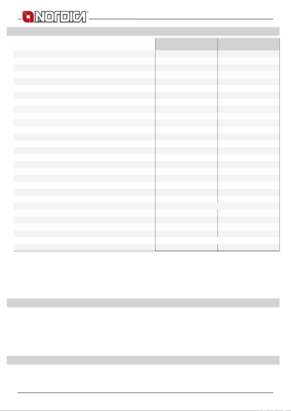
2. TECHNICAL DATA
TERMOCUCINOTTA EVO DSA - TERMOCUCINOTTA DSA
Denition: in accordance with EN 13240
Constructive system
Global thermal power in kW
Nominal thermal power in kW
Power given back to water in kW
Power given back to the room in kW
Hourly wood consumption in kg / h (wood with 20% humidity)
Efciency in %
CO measured at 13% oxygen in %
Smoke outlet diameter in mm
Chimney height - dimension in mm (#)
Fluid contents of the exchanger in L (litres)
Chimney draught in Pa (mm H2O)
Boiler connections (Ø)
Automatic discharge pipe diameter (Ø)
Outer air inlet Ø in mm (minimum surface cm2)
Exhaust gas emission in g/s – wood
Exhaust gas temperature in °C - wood
Optimal working temperature in °C
Max. working pressure in bar (expansion vessel Open - Closed)
Hearth opening size in mm (W x H)
Hearth size in mm (W x H x D)
Oven size in mm (W x H x D)
Type of grill
Height in mm
Width in mm
Depth in mm
Weight in Kg
Fire prevention safety distances
heatable m3 (30 kcal/h x m3) (# #)
(#) 200 mm diameter can be used with ue of no less than 6 m.
(# #) For those buildings in which the thermal insulation does not correspond to the instructions on heat protection, the heating volume
of the product is: favourable type of building (30 Kcal/h x m3); less favourable type of building (40 Kcal/h x m3); unfavourable type of
building (50 Kcal/h x m3).
With thermal insulation in accordance with the regulations regarding energy saving, the heated volume is greater. With temporary heating,
in the event of interruptions which last more than 8 hours, the heating capacity is reduced by about 25%.
IMPORTANT: The power of the connected heating system must be proportional to the power transferred to the water by the thermoproduct;
a charge which is too low does not allow regular oven operation, while a charge which is too high prevents adequate radiator heating.
TERMOCUCINOTTA EVO
1 1
21,4 30,5
16,9 22,6
11,9 15,7
5 6,9
4,9 6,8
78,8 74
0,09 (1152 mg/Nm
150 150
5m – 220x220 Ø220 5m – 220x220 Ø220
20,5 20,5
17 - 20 (1,7 - 2,0) 17 - 20 (1,7 - 2,0)
1 ”F gas 1 ”F gas
3/4”M gas 3/4”M gas
150 (100 cm2) 150 (100 cm2)
14,7 21,7
297 325
70 - 75 70 - 75
VEA 1,5 bar - VEC 3 bar VEA 1,5 bar - VEC 3 bar
405 x 260 405 x 260
415 x 275 x 475 415 x 275 x 475
/ /
860 860
682 682
679 679
205 205
484 650
3
) 0,32 (3996 mg/Nm3)
Chapter SAFETY
TERMOCUCINOTTA DSA
Movable - at
3. GENERAL PRECAUTIONS
La NORDICA S.p.A. responsibility is limited to the supply of the appliance.
The installation must be carried out scrupulously according to the instructions provided in this manual and the rules of the profession.
Installation must only be carried out by a qualied technician who works on behalf of companies suitable to assume the entire responsibility
of the system as a whole.
La NORDICA S.p.A. declines any responsibility for the product that has been modied without written authorisation as well as
for the use of non-original spare parts. NO MODIFICATIONS CAN BE CARRIED OUT TO THE APPLIANCE. La NORDICA S.p.A.
cannot be held responsible for lack of respect for such precautions.
It is OBLIGATORY to respect the National and European rules, local regulations concerning building matter and also reproof
rules.
4. INSTALLATION REGULATIONS
Installation of the product and auxiliary equipment in relation to the heating system must comply with all current Standards and Regulations
and to those envisioned by the law.
The installation and the relating to the connections of the system, the commissioning and the check of the correct functioning must
be carried out in compliance with the regulations in force by authorised professional personnel with the requisites required by the law,
being national, regional, provincial or town council present in the country within which the appliance is installed, besides these present
18 7093041
TERMOCUCINOTTA EVO DSA - TERMOCUCINOTTA DSA
instructions.
Installation must be carried out by authorised personnel who must provide the buyer with a system declaration of conformity and will
assume full responsibility for nal installation and as a consequence the correct functioning of the installed product.
Before installing the appliance, carry out the following checks:
• Make sure that the oor can support the weight of the appliance, and if it is made of ammable material, provide suitable insulation
(DIMENSIONS ACCORDING TO REGIONAL REGULATIONS).
• Make sure that there is adequate ventilation in the room where the appliance is to be installed, with particular attention to windows
and doors with tight closing (seal ropes).
• Do not install the appliance in rooms containing collective ventilation ducts, hoods with or without extractor, type B gas appliances,
heat pumps, or other appliances that, operating at the same time, can put the room in depression (ref. UNI 10683 standard)
• Make sure that the ue and the pipes to which the appliance will be connected are suitable for its operation. It is not allowed the
connection of various appliances to the same chimney.
• The diameter of the opening for connection to the chimney must at least correspond to the diameter of the ue gas pipe. The opening
must be equipped with a wall connection for the insertion of the exhaust pipe and a rosette.
• The installation must be appropriate and has to allow the cleaning and maintenance of the product and the ue.
Before installation, accurately wash the pipes of the system in order to remove any residuals that could compromise the correct functioning
of the appliance.
IMPORTANT:
a) It would be appropriate to install an automatic or manual air valve to allow the air outlet from the plumbing system;
b) In case of water leaking, close the water supply and promptly warn the after sales technical service;
c) The system working pressure must periodically be checked.
d) If not using the boiler for a long period of time, it is recommended that the after sales technical service is contacted to carry out at least
the following operations:
• close the water taps of both the thermal system and the domestic hot water system;
• empty the thermal system and the domestic hot water system if there is risk of freezing.
The DSA thermo appliances, can be installed in both an OPEN expansion Tank system (see chapter 4.1) and a CLOSED expansion Tank
system (see chapter 4.2).
La NORDICA S.p.A. declines all responsibility for damage to things and/or persons caused by the system. In addition, it is not
responsible for any product modied without authorisation and even less for the use of non original spare parts.
Your regular local chimney sweep must be informed about the installation of the appliance so that he can check the correct connection to
the chimney.
4.1. OPEN expansion Tank system
It is COMPULSORY that the OPEN expansion Tank system is provided with:
1. OPEN EXPANSION Tank: which has a capacity of 10% of total water content of thermo-product and of the installation. This is
installed at the highest point of the system, at least 2 m over the radiator that is at the highest level.
2. SAFETY PIPE : that connects through the shortest way, without descending or siphoning parts, the delivery of thermo-product to
the upper side of open expansion tank. ATTENTION: The inside diameter of the supply pipe which connects the thermoproduct with
the open expansion vessel must be equal to the internal diameter of the supply junction present in the thermoproduct. The above
mentioned connection pipe must be without siphoning parts.
3. LOAD PIPE : which connects the bottom of open expansion tank with the return pipe of installation. The minimum diameter must
be ¾” gas. All those parts must no have for any reason meditate intercept bodies that could accidentally exclude them and must be
placed in rooms which are protected from frost. On the contrary, if they freeze, the boiler body could break or even explode. In case
of frost placing it will be right to add a proper percentage of antifreeze liquid to the water of installation in order to delete the whole
problem. In no way there must be water circulation in the open expansion tank between the safety and loading pipe. This would cause
the water oxygenation and the consequent corrosion of thermo-product and installation in a very short time.
4. AUTOMATIC THERMAL DISCHARGE VALVE DSA which is a further positive safety that prevents the boiling even when electric
energy is missing. It is made by a valve cover like a pressure safety valve which differs from it as it opens by reaching a pre-calibrated
temperature (normally at 94 – 95°C) and unload hot water from the installation delivery. This will be replaced with as much cold water
coming from the open expansion tank loading pipe of open tank by draining away the excessive heat.
5. SAFETY VALVE FROM 1,5 bar: maximum operation pressure allowed for the system is 1,5 bar (equal to 15 m of the water column).
Higher pressures can cause deformation and breakage of the boiler body.
6. SAFETY DEVICES envisioned by Regulations in vigour.
7. CIRCULATION PUMP : . It would be better to install it on the return in order to avoid that it could disconnect itself at very high water
temperatures but checking that it does not drive water in the open expansion tank otherwise it should cause a continuous water
oxygenation with consequent, fast corrosion of boiler body. It must be not to avoid a forced circulation in the open expansion tank.
Furthermore it must be electrically connected to a thermostat or a electronic control unit that can be purchased with the thermoreplace as OPTIONAL part.
8. ANTI-CONDENSATION MIXING VALVE – (see chapter 4.3)
ATTENTION: temperature safety sensors must be in place on the machine or at a distance no greater than 30 cm from the ow connection
of the thermo-product. Whenever the thermo products lack a device, those missing can be installed on the thermo product ow pipe,
within a distance no greater than 1m from the thermo product. All those parts must no have for any reason meditate intercept bodies
that could accidentally exclude them and must be placed in rooms which are protected from frost. On the contrary, if they freeze, the
boiler body could break or even explode.
ATTENTION: For no reason must the re be ignited before the system has been completely lled with water; doing this would
lead to serious damage of the entire structure. The system must be lled by means of the loading pipe directly from the open tank
in a way to prevent an excessive pressure of the water network deforming the body of the thermo heating stove.
7093041 19

TERMOCUCINOTTA EVO DSA - TERMOCUCINOTTA DSA
The system must be kept constantly full of water even during the periods when the use of the thermo-heating stove is not requested. During
the winter, inactivity must be faced with the addition of antifreeze.
4.2. CLOSED expansion Tank system
It is COMPULSORY that the CLOSED expansion Tank system is provided with:
1. A SAFETY VALVE - maximum operation pressure allowed for the system is : see DECLARATION OF PERFORMANCE - CE
MARKING INFORMATION. Higher pressures can cause deformation and breakage of the boiler body. ATTENTION: The inside
diameter of the supply pipe which connects the thermoproduct with the security valve must be equal to the internal diameter of the
supply junction present in the thermoproduct. The above mentioned connection pipe must be without siphoning parts.
2. ANTI-CONDENSATION MIXING VALVE – (see chapter 4.3)
3. AUTOMATIC THERMAL DISCHARGE VALVE DSA or TEMPERATURE SAFETY RELIEF VALVE, with double safety sensor
4. CLOSED EXPANSION Tank can be installed on the thermo product return pipe. ATTENTION: The inside diameter of the return pipe
which connects the thermoproduct with the closed expansion vessel must be equal to the internal diameter of the return junction
present in the thermoproduct. The above mentioned connection pipe must be without siphoning parts.
5. PUMP CONTROL THERMOSTAT
6. NOISE ALARM ACTIVATION THERMOSTAT
7. NOISE ALARM
8. TEMPERATURE INDICATOR
9. PRESSURE INDICATOR
10. PUMP SYSTEM
ATTENTION: safety sensors must be in place on the machine according to that stated in chapter 4.1. All those parts must no have for any
reason meditate intercept bodies that could accidentally exclude them and must be placed in rooms which are protected from frost. On
the contrary, if they freeze, the boiler body could break or even explode.
IT IS MANDATORY that the thermo products for domestic heating inserted in CLOSED Tank heating systems, must be internally equipped,
with a cooling circuit, prepared by the unit manufacturer, which is activated by a thermal safety valve (see chapter 3.4) which does not
require auxiliary power and can guarantee that the standard set temperature limit is not exceeded. Connection between the power supply
unit and the valve must be free from interceptions. Cooling circuit upstream pressure must be at least 1,5 bar.
4.3. ANTI-CONDENSATION MIXING VALVE OBLIGATORY (purchased as OPTIONAL part)
The Anti-condensation mixing valve nds applications in solid fuel heat generators as it prevents cold water return in the exchanger
Picture 1 at page 73. Routes 1 and 3 are always open and, along with the pump installed on the return (R), they guarantee water circulation
inside the biomass boiler exchanger (CB). An elevated return temperature, allows efciency improvement, reduces formation of smoke
condensation and prolongs the boiler life span.
Valves on the market have different calibrations. La NORDICA advises use of model 55°c with 1” hydraulic connections. Once the valve
calibration temperature is reached, route 2 opens and the boiler water goes to the system via the ow (M).
IMPORTANT lack of installation of the device voids the heat exchanger warranty.
4.4. AUTOMATIC THERMAL DISCHARGE VALVE DSA (purchased as OPTIONAL part)
Solid fuel thermo products must be installed with safety devices determined by laws in vigour. For this reason the thermo products is
equipped with a heat discharge coil.
The heat discharge coil must have one side connected to the water network (Picture 1 at page 73 / Chap. DIMENSIONS - A) and the other
rot drainage network (C). When the safety temperature is reached, the automatic thermal discharge valve DSA, the bulb of which is to
be connected to attachment B, enables the intake of cold water in the boiler coil, discharging the excess heat out of pipe C towards a
conveniently installed drain. Cooling circuit upstream pressure must be at least 1,5 bar.
WARNING: We cannot be made liable for a wrong operation of the plant, when it does not comply with the provisions of these
instructions or when it uses additional products not suitable for this device (see chapter Thermostatic Valve VAST TECHNICAL
DATA SHEET).
4.5. SYSTEM CONNECTION AND FILLING
Some examples, purely indicative of the installation, are reported at chapter INSTALLATION LAY-OUT, while the connections to the
thermoproduct are reported at chapter DIMENSIONS .
ATTENTION: The lling of the system must take place exclusively by the natural fall of the water from the open expansion tank
through the feed pipe in order to avoid that a too high water system grid pressure could change or cause the explosion of
boiler body.
During this phase, open all the bleed valves of the radiators to prevent the formation of air sacks, checking the outlet of water to avoid
unpleasant oodings.
The watertight test of the installation is performed with the pressure of expansion tank open.
The installation must always be full of water even when the thermo-product is not used. During winter season the non use has
to be faced by adding antifreeze substances.
5. FIRE SAFETY
When installing the product, the following safety measures must be observed:
a) In order to ensure sufcient thermal insulation, respect the minimum safety distance from objects or furnishing components ammable
and sensitive to heat (furniture, wood sheathings, fabrics. etc.) and from materials with ammable structure (see Picture 5 at page 78 -
A). All the minimum safety distances are shown on the product data plate and lower values must not be used.
b) In front of the furnace door, in the radiation area there must be no ammable or heat-sensitive objects or material at a distance of less
than 100 cm. This distance can be reduced to 40 cm where a rear-ventilated, heat-resistant protection device is installed in front of the
whole component to protect.
20 7093041
TERMOCUCINOTTA EVO DSA - TERMOCUCINOTTA DSA
c) If the product is installed on a non totally refractory oor, one must foresee a reproof background. The oors made of inammable
material, such as moquette, parquet or cork etc., must be covered by a layer of no-inammable material, for instance ceramic, stone,
glass or steel etc. (size according to regional law). The base must extend at least 50 cm at the front and at least 30 cm at the sides, in
addition to the opening of the loading door (see Picture 5 at page 78 - B).
d) No ammable components (e.g. wall units) must be present above the product.
The Product must always operate exclusively with the ash drawer inserted. The solid combustion residues (ash) must be collected in a
sealed, re resistant container. The Product must never be on in the presence of gaseous emissions or vapours (for example glue for
linoleum, petrol etc.). Never deposit ammable materials near the Product.
During combustion, thermal energy is released which leads to considerable heating of the surfaces, doors, handles, controls, glass parts,
the ue gas pipe and possibly the front part of the appliance. Avoid contact with these elements unless using suitable protective
clothing or accessories (heat resistant gloves, control devices).
Ensure children are aware of these dangers and keep them away from the furnace when it is on.
When using the wrong fuel or one which is too damp, due to deposits present in the ue, a ue re is possible.
5.1. IN A EMERGENCY
If there is a re in the ue connection :
a) Close the loading door and the ash drawer door
b) Close the comburent air registers
c) Use carbon dioxide ( CO2 powder ) extinguishers to put out the re
d) Request the immediate intervention of the Fire Brigade
DO NOT PUT OUT THE FIRE WITH WATER.
When the ue stops burning, have it checked by a specialist to identify any cracks or permeable points.
6. TECHNICAL DESCRIPTION
La NORDICA thermocookers are ideal for holiday ats and weekend houses or as auxiliary heating all year round.
Wooden logs are used as fuel. The appliance works as an intermittent operating appliance.
The thermocooker is composed of galvanised steel sheet plates, enamelled cast iron and thermoradiant ceramic. The furnace is found
inside the boiler made with 4 mm thick steel and reinforced with welded nails. The water from the heating system, which absorbs the heat
produced in the furnace, circulates in the boiler. Inside the furnace, there is a height-adjustable at grill (Picture 9 at page 79).
The furnace is equipped with a panoramic door with ceramic glass (resistant up to 700°C). This allows a fascinating view of the burning
ames. In addition, in this way there is no possibility of sparks or smoke escaping.
Below the oven door there is an extractable wood drawer, with the related closing door (Picture 7 at page 79 A).
ACCESSORIES
TERMOCUCINOTTA - DSA INCLUDED INCLUDED INCLUDED
TERMOCUCINOTTA EVO - DSA INCLUDED INCLUDED INCLUDED
The heating of the room takes place:
a) bymeansofradiation: through the panoramic glass and the hot external surfaces of the stove, heat is radiated into the room.
b) by conduction: through radiators or convectors in the central heating system fed by the hot water produced by the Thermocooker
itself.
The thermocooker is supplied with registers for primary and secondary air and a thermostat with which the combustion air is regulated.
1A - PRIMARY Air Register / AUTOMATIC Thermostat (Picture 7 at page 79 ).
The thermostat has the task of automatically increasing or decreasing combustion.
Dependent on the position chosen, the thermostat will act on the valve which regulates the intake of air into the furnace, placed on the
back of the cooker. Turn it in a clockwise direction from 0 to 5 to make up the re and in an anti-clockwise direction to reduce combustion.
As this is an extremely precise device, it is advisable to turn it carefully and never force the knob.
2A - SECONDARY Air Register (Picture 7 at page 79).
This register must be open (i.e. turned completely to the right), in particular for the combustion of wood (see paragraph NORMAL
OPERATION). The secondary air, passing between the double glass of the re door, heats up and triggers the dual combustion, keeping
the glass clean at the same time (register open).
To ignite the ame follow the instructions below (see Cap. IGNITION) :
• Open the buttery valve placed on the ue gas exhaust pipe must also be opened.
• Position the thermostat knob on position 5 (maximum opening).
• After having started the re with small pieces of wood and waited until it is well lit, adjust the thermostat to the positions corresponding
to the desired heat (0÷5).
• Close the buttery valve placed on the ue gas exhaust pipe must also be opened.
The register regulation necessary in order to obtain nominal caloric output is the following (see Cap. NORMAL OPERATION):
PRIMARY air SECONDARY air TERTIARY air
TERMOCUCINOTTA - DSA POS. 5 OPENED Pre-adjusted
TERMOCUCINOTTA EVO - DSA POS.4 OPENED Pre-adjusted
Poker Glove Height-adjustable cast iron grate
7093041 21

TERMOCUCINOTTA EVO DSA - TERMOCUCINOTTA DSA
7. FLUE
Essential requirements for correct appliance operation:
• the internal section must preferably be circular;
• the appliance must be thermally insulated and impermeable and built with suitable materials which are resistant to heat, combustion
products and any condensation;
• there must be no narrowing and vertical passages with deviations must not be greater than 45°;
• if already used, it must be clean;
• the technical data from the instruction manual must be respected;
If the ues are of a square or rectangular section, the internal edges must be rounded with a radius of not less than 20 mm.
For the rectangular section, the maximum ratio between the sides must be ≤ 1.5.
A section which is too small causes a reduction in draught. A minimum height of 4 m is advisable.
The following materials are FORBIDDEN and compromise the good operation of the appliance: asbestos cement, galvanised steel, rough
and porous internal surfaces. Picture 2 at page 76 shows some example solutions.
The minimum section must be 4 dm2 (for example 20x20 cm) for appliances whose pipe dimensions are less than 200 mm, or 6.25
dm2 (for example 25x25 cm) for appliances with a diameter of more than 200 mm.
The draught created by your ue must be sufcient but not excessive.
A section of the ue which is too large can present a volume which is too large to heat and therefore cause operating difculties for the
appliance; to avoid this, it is necessary to intubate the appliance for its entire height. A section which is too small causes a reduction in
draught.
ATTENTION: as far as concern the realisation of the ue connection and ammable materials please follow the requirements provided by
UNI 10683 standard. The ue must be at a suitably distance from ammable or combustible material using suitable insulation or
an air space.
It is FORBIDDEN to pass system piping or air ducts inside the ue. It is also forbidden to create moveable or xed openings on the ue
itself, for the connection of further different appliances (See chapter CONNECTING A FIREPLACE OR OPEN HEARTH TO THE FLUE).
7.1. CHIMNEY POT
The ue draught depends on the suitability of the chimney pot.
It is therefore essential that, if built in a handcrafted way, the exit section is more than twice the internal section of the ue
(Picture 3 at page 76) .
As it must always go past the ridge of the roof, the chimney pot must ensure exhaust even in the presence of wind (Picture 4 at page 77).
The chimney pot must meet the following requirements:
• Have an internal section equivalent to that of the chimney.
• Have a useful exit section of double the internal section of the ue.
• Be built so as to prevent rain, snow or any foreign body entering the ue.
• Be easy to inspect, for any maintenance and cleaning operations.
7.2. CONNECTION TO THE CHIMNEY
Products with automatic door closing (type 1) must operate, for safety reasons, with the furnace door closed (except during the fuel loading
or ash removal phases).
Products with non-automatic door closing (type 2) must be connected to their own ue.
Operation with doors open is only allowed when supervised.
The connection pipe to the ue must be as short as possible, straight horizontal and positioned slightly in ascent, and watertight.
Connection must be carried out with stable and robust pipes,comply with all current Standards and Regulations and to those envisioned
by the law, and be hermetically secured to the ue. The internal diameter of the connection pipe must correspond to the external diameter
of the cooker ue gas exhaust stub pipe (DIN 1298).
ATTENTION: as far as concern the realisation of the ue connection and ammable materials please follow the requirements provided by
UNI 10683 standard. The ue must be properly spaced from any ammable materials or fuels through a proper insulation or an air cavity.
Minimum distance safety 25 cm.
For a better working of the appliance, it is suggested to have a ue draught of 17 - 20 Pascal (= 1,7 - 2,0 mm of column of water).
The measurement has always to be carried out with hot device (rated thermal performance).
When the depression exceeds 20 Pa (=2,0 mm of column of water), it is necessary to reduce the same by installing an additional draught
regulator (buttery valve) on the exhaust pipe or in the chimney, according to the regulations in force.
For correct appliance operation, it is essential that sufcient air for combustion is introduced into the place of installation (see paragraph
AIR FLOW IN THE PLACE OF INSTALLATION DURING COMBUSTION).
7.3. CONNECTING A FIREPLACE OR OPEN HEARTH TO THE FLUE
The ue gas channel is the stretch of piping which connects the thermo-product to the ue. In the connection, these simple but extremely
important principles must be respected:
• under no circumstances use a ue gas channel with a diameter less than that of the exhaust clamp with which the thermo-product is
equipped;
• each metre of the horizontal stretch of the ue gas channel causes a slight loss of head which must be compensated if necessary by
elevating the ue;
• the horizontal stretch must never exceed 2 metres (UNI 10683);
• each bend of the ue gas channel slightly reduces the ue draught which must be compensated if necessary by elevating it suitably;
• The UNI 10683 – ITALY regulation requires that under no circumstances must there be more than 2 bends or variations in direction
including the intake into the ue.
22 7093041
TERMOCUCINOTTA EVO DSA - TERMOCUCINOTTA DSA
If the user wishes to use the ue as a replace or open hearth, it is necessary to seal the hood below the entrance point of the ue gas
channel pos. A Picture 6 at page 78.
If the ue is then too big (e.g. 30x40cm or 40x50cm), it is necessary to intubate it with a stainless steel tube with a diameter of at least
200mm, pos. B, taking care to close the remaining spaces between the pipe and the ue immediately under the chimney pot pos. C.
8. AIR FLOW IN THE PLACE OF INSTALLATION DURING COMBUSTION
As the product draw their combustion air from the place of installation, it is MANDATORY that in the place itself, a sufcient quantity of air
is introduced. If windows and doors are airtight (e.g. built according to energy saving criteria), it is possible that the fresh air intake is no
longer guaranteed and this jeopardises the draught of the appliance and your health and safety. It is therefore necessary to guarantee a
supply of fresh air through an external air inlet placed near the appliance or by placing piping for combustion air which leads outside or to
a nearby airy place, with the exception of the boiler room or garage (FORBIDDEN).
IMPORTANT: For a better comfort and corresponding oxygenation of environment, the air can be directly withdrawn at the outside. In order
to do that, the stove can be connected to the external air socket by an junction (see Chap. DIMENSIONS and Picture 9 at page 62). The
connection pipe must be smooth with a minimum diameter of 100 mm. It must have a maximum length of 3 m and have no more than
three bends. If it is directly connected to the outside, it must be equipped with a suitable windbreak.
The intake of air for combustion in the place of installation must not be obstructed during operation of the product. It is absolutely essential
that in environments in which products are operated with a natural chimney draught, as much air as is necessary for combustion is
introduced, i.e. up to 25 (>11kW) m³/hour. The natural recirculation of air must be guaranteed by some xed openings to the outside. Their
size is established by regulations regarding the subject. Ask for information from a chimneys weep. The openings must be protected with
grills and must never be blocked up. An extractor hood (suction) installed in the same room or in a neighbouring one causes a depression in
the environment. This causes the leakage of burnt gas (dense smoke, smell); it is therefore necessary to ensure a greater ow of fresh air.
The depression of an extractor hood can, in the worst case scenario, transform the ue of the product into an external air inlet,
re sucking the ue gases into the environment with very serious consequences for persons.
9. ALLOWED / NOT ALLOWED FUELS
Allowed fuels are logs. Use exclusively dry logs (max. content of water 20%). Maximum 3 logs should be loaded. The pieces of wood
should have a length of ca. 20-30 cm and a maximum circumference of 30-35 cm.
Compressed not worked-out wood briquettes must be used carefully to avoid overheating that may damage the device, since
these have a very high caloric value.
The wood used as fuel must have a humidity content lower than the 20% and must be stored in a dry place. Humid wood tends to burn
less easily, since it is necessary a greater quantity of energy to let the existing water evaporate. Moreover, humid content involves
the disadvantage that, when temperature decreases, the water condensates earlier in the hearth and therefore in the stack causing a
remarkable deposit of soot with following possible risk of re of the same.
Fresh wood contains about 60% of H2O, therefore it is not suitable to be burnt.
It is necessary to place this wood in a dry and ventilated place (for example under a roong) for at least two years before using it.
Besides others, it is not possible to burn: carbon, cuttings, waste of bark and panels, humid wood or wood treated with paints,
plastic materials; in this case, the warranty on the device becomes void.
Paper and cardboard must be used only to light the re.
The combustion of waste is FORBIDDEN and would even damage the appliance and the ue, causing health damages and claims by
the neighborhood owing to the bad smell.
The wood is not a fuel which allows a continuous operation of the appliance, as consequence the heating all over the night is not possible.
Variety kg/mc kWh/kg moistness 20%
Beech
Oak
Elm
Poplar
Larch*
Spruce*
Scots pine *
750 4,0
900 4,2
640 4,1
470 4,1
660 4,4
450 4,5
550 4,4
* RESINOUS WOOD NOT SUITABLE FOR THE BURNING
ATTENTION : the continuous and protracted use of aromatic wood (eucalyptus, myrtle etc.) quickly damages the cast iron parts
(cleavage) of the product.
The declared technical data have been achieved by burning beech wood class “A1” according to the requirement UNI EN ISO 17225-5
and wood moisture content less than 20%. By burning a different kind of wood the efciency of the product itself could change and some
specic adjustments on the appliance could be needed.
7093041 23

TERMOCUCINOTTA EVO DSA - TERMOCUCINOTTA DSA
10. LIGHTING
ATTENTION: never light for any reason if the installation is not completely full of water in order to avoid a serious damage of
the whole structure. IABSOLUTELY DO NOT LIGHT THE FIRE IN THE APPLIANCE IN THE TOTAL OR PARTIAL ABSENCE OF
WATER (NOT EVEN FOR CHECKING), AS IT COULD BE IRREMEDIABLY RUINED. IN SUCH CASE THE WARRANTY ON THE
APPLIANCE IS VOIDED.
WARNING: After the rst ignition you can smell bad odours (owing to the drying of the glue used in the garnitures or of the paint) which
disappear after a brief using of the appliance. It must be ensured, in any case, a good ventilation of the environment. Upon the rst
ignition we suggest loading a reduced quantity of fuel and slightly increasing the caloric value of the equipment
To perform a correct rst lighting of the products treated with paints for high temperature, it is necessary to know the following information:
• the construction materials of the involved products are not homogeneous, in fact there are simultaneously parts in cast iron, steel,
refractory material and majolica;
• the temperature to which the body of the product is subject is not homogeneous: from area to area, variable temperatures within the
range of 300°C - 500°C are detected;
• during its life, the product is subject to alternated lighting and extinguishing cycles in the same day, as well as to cycles of intense use
or of absolute standstill when season changes;
• the new appliance, before being considered seasoned has to be subject to many start cycles to allow all materials and paints to
complete the various elastic stresses;
• in detail, initially it is possible to remark the emission of smells typical of metals subject to great thermal stress, as well as of wet paint.
This paint, although during the manufacture it is backed at 250 °C for some hours, must exceed many times and for a given period of
time the temperature of 350 °C before becoming completely embedded in the metallic surfaces.
Therefore, it is extremely relevant to take these easy steps during the lighting:
1. Make sure that a strong air change is assured in the room where the appliance is installed.
2. During the rst starts, do not load excessively the combustion chamber (about half the quantity indicated in the instructions manual)
and keep the product continuously ON for at least 6-10 hours with the registers less open than the value indicated in the instructions
manual.
3. Repeat this operation for at least 4-5 or more times, according to your possibilities.
4. Then load more and more fuel (following in any case the provisions contained in the installation booklet concerning maximum load)
and, if possible, keep the lighting periods long avoiding, at least in this initial phase, short ON/OFF cycles.
5. During the rst starts, no object should be leaned on the appliance and in detail on enameled surfaces. Enameled surfaces
must not be touched during heating.
6. Once the «break-in» has been completed, it is possible to use the product as the motor of a car, avoiding abrupt heating with excessive
loads.
To light the re, it is suggested to use small wood pieces together with paper or other traded lighting means.
It is FORBIDDEN to use any liquid substance as for ex. alcohol, gasoline, oil and similar.
ATTENTION: during the rst lightings there could be a solid smokes condensation with a small escape of water from the appliance:
this event will expire in a very short time but if it persists it will be necessary to check the chimney draught.
The openings for air (primary and secondary) must be opened together (you must open the eventual Ignition control, and buttery valve
placed on the pipe of smokes exhaust). When the wood starts burning, you may load other fuels and adjust the air for combustion
according to the instructions on paragraph DESCRIPTION.
Please always be present during this phase.
Never overload the appliance (see the technical table - max quantity of fuel that can be loaded / hourly consumption). Too much fuel and
too much air for combustion can cause overheating and therefore damage the appliance. The warranty does not cover the damages
due to overheating of the equipment.
Never switch on the device when there are combustible gases in the room.
10.1. LOW EMISSION re lighting
Smokeless combustion is a way of lighting a re able to signicantly reduce the emission of harmful substances. The wood burns gradually
from the top downwards, so combustion is slower and more controlled. Burnt gases pass through the high temperatures of the ame and
therefore burn almost completely.
Place the logs in the hearth a certain distance apart as shown in the Picture 8 at page 79. Arrange the largest at the bottom and the smallest
at the top, or vertically in the case of tall narrow combustion chambers. Place the re starter module on top of the pile, arranging the rst
logs in the module at right angles to the pile of wood.
Fire STARTER MODULE. This re starter module replaces a paper or cardboard starter.
Prepare four logs, 20 cm long with a cross section of 3 cm by 3 cm. Cross the four logs and place them on top of the pile of wood at
right angles, with the re lighter (wax impregnated wood bre for example) in the middle. The re can be lit with a match. If you want,
you can use thinner pieces of wood. In this case, you will need a larger quantity.
Keep the ue gas exhaust valve and combustion air regulator open.
After lighting the re, leave the combustion air regulator open in the position shown:
FUEL PRIMARY Air SECONDARY Air TERTIARY air
Wood Position 0 1/2 OPEN PRE-ADJUSTED
IMPORTANT:
• do not add further wood between one complete load and the next;
• do not suffocate the re by closing the air intakes;
• regular cleaning by a chimney sweep reduces ne particle emissions.
• These instructions are backed by ENERGIA Legno SVIZZERA www.energia-legno.ch
24 7093041

TERMOCUCINOTTA EVO DSA - TERMOCUCINOTTA DSA
11. NORMAL OPERATION
IMPORTANT: For safety reasons the door of the hearth can be opened only for the loading of the fuel. The hearth door must
always remain closed during operation or rest.
After having positioned the registers correctly, insert the indicated hourly wood load avoiding overloads that cause anomalous stresses
and deformations. You should always use the product with the door closed in order to avoid damages due to overheating (forge
effect). The inobservance of this rule makes the warranty expire.
For safety reasons the door of the appliances with constructive system 1, must be opened only for the loading of the fuel or for removing
the ashes, while during the operation and the rest, the door of the hearth must remain closed.
The appliances with constructive system 2 must be connected to their own ue. The operating with open door is allowed under supervision.
With the controls positioned on the front of the appliance it is possible to adjust the heat emission of the hearth. They have to be opened
according to the caloric need. The best combustion (with minimum emissions) is reached when, by loading the wood, most part of the air
for combustion ows through the secondary air register.
Never overload the appliance (see the hourly wood load in the table here below). Too much fuel and too much air for the combustion may
cause overheating and then damage the stove. You should always use the appliance with the door closed in order to avoid damages due
to overheating (forge effect). The inobservance of this rule makes the warranty expire.
The adjustment of the registers necessary to reach the rated caloric yield with a depression at the stack of 17-20 Pa 1,7-2 mm of column
of water) is the following one: see chapter TECHNICAL DESCRIPTION. The appliance works as an intermittent operating appliance.
In the event that the water temperature exceeds the tripping temperature of the safety devices, immediately suspend the feeding
of wood, and make sure that the water temperature and the ame decrease, eliminating the causes of the overheating (if necessary
by closing the air register).
If the water system is connected in the appliance, the hot water tap can be opened to speed up the cooling of the appliance.
Besides the adjustment of the air for the combustion, the intensity of the combustion and consequently the thermal performance of the
device is inuenced by the stack. A good draught of the stack requires a stricter adjustment of air for combustion, while a poor draught
requires a more precise adjustment of air for combustion.
To verify the good combustion, check whether the smoke coming out from the stack is transparent.
If it is white, it means that the device is not properly adjusted or the wood is too wet; if instead the smoke is gray or black, it signals that the
combustion is not complete (it is necessary a greater quantity of secondary air).
WARNING: When fuel is added onto the embers in the absence of a ame, a considerable amount of fumes may develop. Should this
happen, an explosive mixture of gas and air may form, and in extreme cases an explosion may occur. For safety reasons it is advisable
to perform a new lighting procedure with the use of small strips.
11.1. USE OF THE OVEN (If present)
Thanks to the air ow for the combustion, the temperature of the oven may become remarkably affected. A sufcient ue of the chimney
and of the channels, well cleaned for the ow of burning smokes around the oven are fundamental for a good cooking result. The oven pan
may be located on different plans. Thick cakes and big roasts must be introduced in the lowest level. Flat cakes and biscuits must reach
the medium level. The upper level may be used to heat or grill.
The oven pan and the chrome plated oven grille may be located on different plans (see chapter Technical Description - ACCESSORIES).
When cooking food with high humidity, cakes with fruit or fruit itself, water of condensation will be produced. During the cooking process
some water vapour in the form of drops of condensed water can deposit onto the top and the side of the door. It is a physical phenomenon.
By opening the door briey and carefully (1 or 2 times, or even often in case of longer cooking times) you can let out the steam from the
cooking compartment and reduce condensation signicantly.
The appliance is equipped with a cast iron furnace grill which can be removed using a specic handle. The upper position optimises the
use of the hotplate while the lower one optimises water and oven heating Picture 9 at page 79.
11.2. ELECTRICAL POWER SUPPLY FAILURE
In the event of an unexpected electrical power supply failure during normal system operation, it will be necessary to carry out these simple
manoeuvres to prevent the water in the boiler starting to boil as a consequence of the lack of pump operation.
1. Raise the moveable furnace grill (if present ) to the highest level in order to reduce the exchange surface exposed to the heat of the
ame.
2. Close the primary and secondary air registers in addition to turning the thermostat to 0 ( if present).
3. Open the oven door (if present) in order to favour the elimination of the internal heat.
4. Open the ue gas register ; in this way, it will deviate the residual heat still produced towards the chimney.
11.3. OPERATION IN TRANSITION PERIODS
During transition periods when the external temperatures are higher, if there is a sudden increase of temperature it can happen that the
combustion gases inside the ue cannot be completely sucked up.
The exhaust gases do not come out completely (intense smell of gas). In this case, shake the grating more frequently and increase the air
for the combustion. Then, load a reduced quantity of fuel in order to permit a rapid burning (growing up of the ames) and the stabilization
of the draught. Then, check that all openings for the cleaning and the connections to the stack are air-tigh.
In case of doubt, do not operate the product.
ATTENTION: never light for any reason if the installation is not completely full of water in order to avoid a serious damage of the whole
structure. The installation must always be full of water even when the thermo-replace is not used. A possible no use during winter
season must be faced by adding antifreeze substances.
7093041 25

TERMOCUCINOTTA EVO DSA - TERMOCUCINOTTA DSA
11.4. SUMMER USE
The system must be completely lled with water. The absence of water in the system would lead to serious damage of the entire
structure.
ATTENTION: For no reason must the re be ignited before the system has been completely lled with water; doing this would lead to
serious damage of the entire structure.In order to prevent water boiling, the circulation pump must be always in function in order to drain
on the radiators, or on the puffer, or on any other thermal absorption structure the heat given from the boiler to the water. If the pump
does not circulate or for any reason the water temperature exceeds 95°C, acts the DSA valve discharging heat in the throughway water.
It is recommended to supervise the water temperature in the appliance during summer use to avoid recurrent interventions of the DSA
valve which may jeopardize its good operation.
To use the wood burning appliance exclusively for cooking foods for example during the summer period it is necessary to lift the movable
grill (If present) to the maximum height to bypass as much as possible the surfaces of exchange able to yield heat to the water; the
smoke register shall be kept open (If present) to encourage the exit of hot smoke having heated the cast iron plate (cooking function –
HOTPLATE USE).
12. MAINTENANCE AND CARE
Check the external air intake, by cleaning it, at least once a year. The stack must be regularly swept by the chimney sweeper.
Let your chimney sweeper in charge of your area check the regular installation of the device, the connection to the stack and the aeration.
IMPORTANT: The maintenance must be carried out only and exclusively with cold device . You should only use spare parts approved
and supplied by La NORDICA. Please contact your specialized retailer if you require spare parts. YOU MUST NOT MAKE ANY
CHANGES TO THE DEVICE!!!
12.1. GLASS CLEANING
Thanks to a specic inlet of secondary air, the accumulation of dirty sediments on the glass-door is reduced with efcacy. Nevertheless this
can never be avoided by using solid fuels ( particularly wet wood ) and it has not to be understood as a defect of the appliance.
IMPORTANT: The cleaning of the sight glass must be carried out only and exclusively with cold device to avoid the explosion of
the same. For the cleaning, it is possible to use specic products or a wet newspaper paper ball passed in the ash to rub it. Do not use
cloths, abrasive or chemically aggressive products by cleaning the hearth glass.
The correct lighting phase, the use of proper quantities and types of fuels, the correct position of the secondary air regulator, enough
draught of the chimney-ue and the presence of combustion air are the essential elements for the optimal functioning of the appliance and
for the cleaning of the glass.
BREAK OF GLASSES: Given that the glass-ceramic glasses resist up to a heat shock of 750°C, they are not subject to thermal
shocks. Their break can be caused only by mechanic shocks (bumps or violent closure of the door, etc.). Therefore, their
replacement is not included in the warranty.
12.2. CLEANING OUT THE ASHES
All the devices are equipped with a hearth grating and an ash drawer for the collection of the ashes Picture 9 at page 79.
It is suggested to empty periodically the ash drawer and to avoid it lls completely in order not to overheat the grating. Moreover, it is
suggested to leave always 3-4 cm of ash in the hearth.
CAUTION: The ashes removed from the hearth have to be stored in a container made of re-resistant material equipped with an
air-tight cover. The container has to be placed on a re-resistant oor, far from ammable materials up to the switching off
and complete cooling.
12.3. CLEANING THE FLUE
The correct lighting phase, the use of proper quantities and types of fuels, the correct position of the secondary air regulator, enough
draught of the chimney-ue and the presence of combustion air are the essential elements for the optimal functioning of the appliance.
26 7093041
TERMOCUCINOTTA EVO DSA - TERMOCUCINOTTA DSA
The device should be completely cleaned at least once a year or every time it is needed (in case of bad working and low yield). An
excessive deposit of soot can cause problems in the discharge of smokes and re in the ue.
The cleaning must be carried out exclusively with cold equipment. This operation should be carried out by a chimney sweeper who
can simultaneously perform an audit of the ue (checking of possible deposits).
12.4. SUMMER STOP
After cleaning the hearth, chimney and hood, totally eliminating the ash and other eventual residues, close all the doors of the hearth
and the relevant registers; in case you disconnect the appliance from the chimney you must close its openings in order to let work others
possible appliances connected to the same ue.
We suggest performing the cleaning operation of the ue at least once per year; verifying in the meantime the actual status of the rope
seals, which cannot ensure the good operation of the equipment if they are not in good condition and are not making a good seal! In this
case the seals must be replaced.
In presence of dampness in the room where the stove has been placed, we advise you to put absorbent salts into the hearth.
If you want to keep for long the aesthetic look of the cooker it is important to protect its internal walls in row cast iron with neutral Vaseline.
Check the water level in the expansion tank and remove any air from the system by bleeding the radiators; also check to make sure that
the plumbing and electrical accessories (control unit, circulator) are working properly.
ATTENTION: For no reason must the re be ignited before the system has been completely lled with water; doing this would lead to
serious damage of the entire structure. The installation must always be full of water even when the appliance is not used.
12.5. MAJOLICAS (If present)
La NORDICA has chosen majolica tiles, which are the result of high-quality artisan work. As they are completely carried out by hand, the
majolica may present crackles, speckles, and shadings. These characteristics certify their precious origin.
Enamel and majolica, due to their different coefcient of dilatation, produce microcrackles, which show their authentic feature.
For the cleaning of the majolica we suggest you to use a soft and dry cloth; if you use a detergent or liquid, the latter might soak in
and highlight the crackles permanently.
12.6. PRODUCTS MADE OF NATURAL STONE (If present)
Natural stone has to be cleaned with very thin abrasive paper or with an abrasive sponge. Do NOT use any cleanser or uid.
12.7. VARNISHED PRODUCTS (If present)
After some years of product use a change in the varnished details colour is totally normal. This is due to the considerable temperature
range the product is subject to whenever in use and to the varnish ageing of time passing by.
ATTENTION: before any possible application of the new varnish, do clean and remove all the traces from the surface which has to be
varnished.
12.8. ENAMELLED PRODUCTS (If present)
For the cleaning of enamelled surfaces use soap water or not aggressive and not chemically abrasive detergents. After the cleaning do
NOT let soapy water or any cleanser dry but remove them immediately.
DO NOT use sandpaper or steel wool.
12.9. CHROMIUM-COMPONENTS (If present)
If the components become bluish due to overheating, this can be solved with a suitable product for cleaning. DO NOT use abrasives or
solvents.
12.10. CAST IRON RINGS
The cast iron rings needs to be periodically cleaned by using sandpaper (grain 150) without touching the enamelled parts..
IMPORTANT: to avoid rust DO NOT forget pots or pans on the cold stove. This would create rust rings, unpleasant to see and difcult
to remove.
12.11. LATERAL HANDRAIL (If present)
The handles, the handrail and the tank water (cookers) should be cleaned to cold with a soft cloth and alcohol . DO NOT use abrasives
or solvents.
12.12. CLEANING OF THE HEARTH GRATE
IMPORTANT: if for whatever reason the grill is removed from the furnace, take care to reassemble it with the wider part of the slit facing
downwards (See Picture 9 at page 79). This is to aid furnace cleaning.
12.13. MAINTENANCE ON THE WATER SYSTEM
Excessive incrustation deposits on the inner walls of the hearth considerably reduce the efciency of heat exchange; therefore, remove
these deposits using a steel brush whenever necessary. Never use corrosive substances that can damage the thermo-replace and
the boiler.
With the system switched off, once a year carry out the following checks:
• Check the operation and efciency of the blowdown and safety valves. If they are defective, contact your authorised installer. IT IS
STRICTLY FORBIDDEN TO REMOVE OR TAMPER WITH THE SAFETY DEVICES.
• Check the thermal insulation of the lling pipe and the safety pipe.
• Make sure that the system is lled and under pressure, checking the water level in the expansion tank; also check that it is working
properly and check the efciency of the safety pipe.
7093041 27

TERMOCUCINOTTA EVO DSA - TERMOCUCINOTTA DSA
13. CALCULATION OF THE THERMAL POWER
There is not an absolute rule for calculating the correct necessary power. This power is given according to the space to be heated, but it
depends also largely on the insulation. On an average, the caloric value necessary for a properly insulated room is 30 kcal/h per m3 (for
an external temperature of 0°C).
Given that 1 kW corresponds to 860 kcal/h, it is possible to adopt a value of 35 W/m3.
Let’s suppose one wishes to heat a room of 150 m3 (10 x 6 x 2.5 m) in an insulated apartment. In this case, it is necessary to have 150 m3
x 35 W/m3 = 5250 W or 5,25 kW. As main heating, a 8 kW device is therefore sufcient.
Approximate combustion value Required quantity in relation to 1 kg of dry
wood
Fuel Unit kcal/h kW
Dry wood (15% humidity) kg 3600 4.2 1,00
Wet wood (50% humidity) kg 1850 2.2 1,95
Wood briquettes kg 4000 5.0 0,84
Brown coal briquettes kg 4800 5.6 0,75
Normal anthracite kg 7700 8.9 0,47
Coke kg 6780 7.9 0,53
Natural gas m
Naphtha L 8500 9.9 0,42
Electricity kW/h 860 1.0 4,19
3
7800 9.1 0,46
14. GUARANTEE TERMS
GUARANTEE TERMS
1. La Nordica S.p.A. products are guaranteed, within the European community, for 24 months from the date of purchase.
Purchase has to be proved by means of a valid scal document issued by the seller (receipt, invoice or shipment document) identifying the
purchased product and its purchase and/or delivery date.
WARNING:This conventional guarantee doesnotreplacetheguaranteeregulatedby the European legislation on consumer
rights.
The conventional guarantee is only applicable to the Italian region and to those areas, within the European Community, where the
Authorised Technical Assistance Centres are active (see the www.lanordica-extraame.com website)
It is also limited to the state of residence of the consumer, which must coincide with the premises and/or registered ofce of the seller of
the La Nordica S.p.A. product
These regulations do not apply if the product is purchased within commercial, entrepreneurial, or professional circumstances. In these
cases the product guarantee will be limited to a period of 12 months from the date of purchase.
ITALIAN GUARANTEE
What must be done if there is a product malfunction:
Consult the instructions manual to make sure the malfunction cannot be solved by using the product correctly. Make sure the malfunction
is included in those covered by the guarantee; otherwise the cost of the intervention will be borne entirely by the consumer. When
requesting the intervention of the Assistance service at the Authorised Assistance Centre, always specify: - type of malfunction - model of
the appliance - complete address - phone number
EUROPEAN GUARANTEE
What must be done if there is a product malfunction:
Consult the instructions manual to make sure the malfunction cannot be solved by using the product correctly. Make sure the malfunction
is included in those covered by the guarantee; otherwise the cost of the intervention will be borne entirely by the consumer. Request the
intervention of the Assistance service or the address of the Authorised Technical Assistance Centre to the seller; always specify: type of
malfunction, model of the appliance, complete address and phone number
Ifthemalfunctionarisesintherst6monthsoftheproduct’slife,theconsumerhastherighttohavetheproductrepairedwith
noexpense.
Fromtheseventhtothetwenty-fourthmonth,ifamalfunctionarises,theconsumerwillbearthecostofthecall,whiletheseller
willpayforthemanpowerandforanysparepartsused.
28 7093041

TERMOCUCINOTTA EVO DSA - TERMOCUCINOTTA DSA
2. If the malfunction is linked to external events and/or conditions such as, including but not limited to, insufcient capacity of the systems;
wrong installation and/or maintenance by the personnel which hasn’t got the skills prescribed by the laws of the country of residence of
the consumer; negligence; inability to use the product and wrong maintenance by the consumer, with respect to what is reported and
recommended by the instructions manual of the product, which is part of the sales contract, this guarantee will be void.
Damage to the product that cannot be related to manufacturing defects are also not included in this guarantee. Similarly are excluded
defects related to incorrect operation of the ue, according to the legislation in force in the country at the moment of purchase. Other
exclusions include all product defects due to carelessness, accidental breakdown, tampering and/or damage during transport (scratches,
dents, etc.), interventions carried out by unauthorised personnel and further damage caused by incorrect interventions by the consumer
trying to arrange the initial malfunction.
The following consumables are excluded by the guarantee: gaskets, ceramic or tempered glasses, cast iron grilles or coatings, refractory
materials (e.g. Nordiker or others), painted, chrome-plated or golden parts, majolica ware, handles, the brazier and its related components.
For Idro products the heat exchanger is not covered by the guarantee if a suitable condensation-proof circuit is not set up to ensure a
return temperature of the device of at least 55°C. The guarantee excludes all the external components on which the consumer can directly
operate during use and/or maintenance or that can be subject to wear and/or rust and stains on steel due to aggressive detergents.
If malfunctions are signalled which are not later conrmed during check by an authorised technician, the cost of the intervention will be
borne entirely by the consumer.
3. If it is not possible to restore product conformity by repairing it, the product/component will be replaced, the guarantee expiration date
and conditions will remain the same established when the product/component to be replaced has been purchased.
4. La Nordica S.p.A. cannot be held liable for injury or damage which may - either directly or indirectly - be caused to persons, animals
and property ensuing from failure to observe all the instructions provided in the relevant instruction manual and the warnings regarding
installation, use and maintenance of the product, that can also be downloaded on the website.
5. Interventions for adjusting and/or regulating the product for the type of fuel or other reasons are excluded by the guarantee.
6. If the product is repaired in one of the Authorised Technical Assistance Centres indicated by La Nordica S.p.A. and if the product is
replaced, transport will be free of charge. If the technician can repair the product at the user’s place of residence and they refuse, transport
to the workshop and redelivery will be paid by the consumer.
7. After the 24 months of the guarantee have elapsed any repair intervention cost will be completely borne by the consumer.
8. In the case of disputes the only competent court is that of the La Nordica S.p.A. registered ofce - (Vicenza-Italy)
ADDITIONAL WARNINGS
• Only use the fuel recommended by the manufacturer. The product must not be used as an incinerator.
• Do not use the product as a ladder or supporting structure.
• Do not place laundry on the product to dry it. Any clothes-horse or similar objects must be kept at due distance from the product. Danger
of re or damage to the coating.
• The user is fully liable for any incorrect use of the product. The manufacturer bears no civil or criminal liability for incorrect use.
• Unauthorised tampering of any nature or replacement of spare parts of the product with non-original parts may endanger the operator
and the manufacturer bears no civil or criminal liability for this.
• Large parts of the surface of the product can get very hot (door, handle, glass, smoke outlet pipes, etc.). Please therefore avoid coming
into contact with these parts without wearing suitable protective clothing or using appropriate measures, such as heat protective gloves.
• DO NOT use the product with the door open or if the glass is broken.
• The product must be electrically connected to a system equipped with an operational earthing system.
• Turn off the product in the event of a failure or malfunctioning.
• Do not wash the product with water. Water may penetrate into the unit and cause faults in the electrical insulation. This can cause
electric shocks.
• Installations not complying with the regulations in force, as well as incorrect use and failure to comply with the maintenance scheduled
by the manufacturer, will invalidate the guarantee.
7093041 29

TERMOCUCINOTTA EVO DSA - TERMOCUCINOTTA DSA
Das auf dem Produkt oder derVerpackung angebrachte Symbol besagt, dass das Produkt nicht als normaler
Hausmull anzusehen ist, sondern bei speziellen Sammelstellen für das Recycling von Elelktro- und ElektronikAltgeraten abzugeben ist. Durch die ordnungsgemäße Entsorgung dieses Produktes werden mögliche negative
Folgen vermieden, die aus einer unsachgemäßen Entsorgung. des Produktes entstehen konnten. Ausführlichere
Informationen zum Recycling, dieses Produktes liefern das Gemeindeamt, der örtliche Müllentsorgungsdienst oder
der Händler, bei dem das Produkt gekauft wurde
KONFORMITÄTSERKLÄRUNG DES HERSTELLERS
Betreff: Fehlen von Asbest und Kadmium
Wir bestätigen, dass die verwendeten Materialen oder Teilen für die Herstellung der La Nordica Geräte ohne Asbest und
Derivat sind und auch das Lot für das Schweißen immer ohne Kadmium ist.
Betreff: Ordnung CE n. 1935/2004.
Wir erklären in alleiniger Verantwortung, dass die Materialen der Teile, die für den Kontakt mit Lebensmitteln vorgesehen
sind, für die Nahrungsbenutzung geeignet sind und der Richtlinien CE n. 1935/2004 erfüllen.
DEUTSCH - INHALTSVERZEICHNIS
1. INSTALLATION ...............................................................................................................................................................................3
2. TECHNISCHE DATEN ...................................................................................................................................................................31
3. ALLGEMEINE HINWEISE ............................................................................................................................................................ 31
4. INSTALLATIONSVORSCHRIFTEN ..............................................................................................................................................31
4.1. OFFENE Ausdehnungsgefäß........................................................................................................................................................................32
4.2. GESCHLOSSENE Ausdehnungsgefäß .......................................................................................................................................................33
4.3. ANTIKONDENSATIONSMISCHVENTIL VERPFLICHTEND (als OPTIONAL erhältlich ist) ........................................................................33
4.4. AUTOMATISCHE WAERMEABLASSVENTIL DSA (als OPTIONAL erhältlich ist) ......................................................................................33
4.5. VERBINDUNG UND LADEN DER ANLAGE ................................................................................................................................................33
5. BRANDSCHUTZ ............................................................................................................................................................................34
5.1. SOFORTIGES EINSCHREITEN ...................................................................................................................................................................34
6. TECHNISCHE BESCHREIBUNG ..................................................................................................................................................34
7. RAUCHABZUG .............................................................................................................................................................................35
7.1. SCHORNSTEINPOSITION ...........................................................................................................................................................................35
7.2. ANSCHLUSS AN DEN SCHORNSTEIN .......................................................................................................................................................35
7.3. ANSCHLUSS AN DEN RAUCHABZUG EINES OFFENEN KAMINS ...........................................................................................................36
8. LUFTZUSTROM AM INSTALLATIONSORT WÄHREND DER VERBRENNUNG .......................................................................36
9. ZULÄSSIGE / UNZULÄSSIGE BRENNSTOFFE .......................................................................................................................... 36
10. ANFEUERUNG ..............................................................................................................................................................................37
10.1. EMISSIONSARMES Anfeuern ......................................................................................................................................................................37
11. NORMALER BETRIEB .................................................................................................................................................................. 38
11.1. BACKEN (wenn anwesend) ..........................................................................................................................................................................38
11.2. STROMAUSFALL ........................................................................................................................................................................................39
11.3. BETRIEB IN DEN ÜBERGANGSPERIODEN ...............................................................................................................................................39
11.4. SOMMERBETRIEB .......................................................................................................................................................................................39
12. WARTUNG UND PFLEGE ............................................................................................................................................................39
12.1. REINIGUNG DES GLASES ..........................................................................................................................................................................39
12.2. REINIGUNG DES ASCHENKASTEN ...........................................................................................................................................................39
12.3. REINIGUNG DES SCHORNSTEINROHRES ...............................................................................................................................................40
12.4. SOMMERPAUSE ..........................................................................................................................................................................................40
12.5. KACHELN (wenn anwesend) ........................................................................................................................................................................40
12.6. PRODUKTE MIT TEILEN AUS NATURSTEIN (wenn anwesend) ................................................................................................................40
12.7. LACKIERTE PRODUKTE (wenn anwesend) ................................................................................................................................................40
12.8. EMAILLIERTE PRODUKTE (wenn anwesend) ............................................................................................................................................40
12.9. VERCHROMTE TEILE (wenn anwesend) ....................................................................................................................................................40
12.10. RINGE AUS GUSSEISEN .............................................................................................................................................................................40
12.11. SEITLICHE HANDLÄUFE (wenn anwesend) ...............................................................................................................................................40
12.12. REINIGUNG DES FEUERROSTES .............................................................................................................................................................40
12.13. WARTUNG DER HYDRAULIKANLAGE .......................................................................................................................................................40
13. FESTSTELLUNG DER WÄRMELEISTUNG .................................................................................................................................41
14. GARANTIEBEDINGUNGEN .........................................................................................................................................................41
15. ALLGEMEINES INSTALLATIONSSCHEMA THERMOKÜCHE ...................................................................................................69
15.1. Thermostatisch gesteuerte Ventil VAST TECHNISCHE PROTOKOLLE ......................................................................................................74
16. MAßE .............................................................................................................................................................................................80
30 7093041

TERMOCUCINOTTA EVO DSA - TERMOCUCINOTTA DSA
2. TECHNISCHE DATEN
Denition: gemäß EN 13240
Bauart
Gesamte Wärmeleistung in kW
Nennwärmeleistung in kW
Wasserwärmeleistung in kW
Raumwarmeleistung in kW
Stündenverbrauch in kg / h (Holz mit 20% Feuchtigkeit)
Wirkungsgrad in %
CO gemessen an 13% Sauerstoff in %
Rauchrohrdurchmesser in mm
Schornsteinrohr in mm
Gehalt Fluessigkeit im Ausstauscher in L
Schornsteinrohr Abzug in Pa (mm H2O)
Kesselanschluss (Ø)
Rohrdurchmesser automatischer Auslass (Ø)
Außenlufteintritt Ø in mm (Mindestoberäche in cm2)
Abgasemission in g/s – Holz
Abgastemperatur im Medium in °C - Holz
Optimale Betriebstemperatur in °C
Arbeitstdruck in bar (OFFENEM - GESCHLOSSENEN)
Größe der Feuerraumöffnung in mm (B x H)
Größe des Feuerraum in mm (B x H x T)
Ausmaße des Backofen in mm (B x H x T)
Rosttyp beweglich - ach
Höhe in mm
Breite in mm
Tiefe in mm
Masse in Kg
Sicherheitsabstände zur Brandverhütung Kapitel BRANDSCHUTZ
m3 Heizungsvermogen (30 kcal/h x m3) (# #)
TERMOCUCINOTTA EVO
1 1
21,4 30,5
16,9 22,6
11,9 15,7
5 6,9
4,9 6,8
78,8 74
0,09 (1152 mg/Nm
150 150
5m – 220x220 Ø220 5m – 220x220 Ø220
20,5 20,5
17 - 20 (1,7 - 2,0) 17 - 20 (1,7 - 2,0)
1 ”F gas 1 ”F gas
3/4”M gas 3/4”M gas
150 (100 cm2) 150 (100 cm2)
14,7 21,7
297 325
70 - 75 70 - 75
VEA 1,5 bar - VEC 3 bar VEA 1,5 bar - VEC 3 bar
405 x 260 405 x 260
415 x 275 x 475 415 x 275 x 475
/ /
860 860
682 682
679 679
205 205
484 650
3
) 0,32 (3996 mg/Nm3)
TERMOCUCINOTTA DSA
(#) Durchmesser 200 mm nutzbar mit Rauchabzug nicht unter 6 m.
(# #) Für Gebäude deren Wärmedämmung nicht der Wärmeschutzverordnung entspricht, beträgt das Raumheizvermögen des Ofens:
günstige Bauweise (30 Kcal/h x m3); weniger günstige Bauweise (40 Kcal/h x m3); ungünstige Bauweise (50 Kcal/h x m3).
Bei Wärmedämmung gemäß Wärmeschutzverordnung erhöht sich das Raumheizvermögen. Bei Zeitweiligheizung mit mehr als 8 Stunden
lang Einstellungen, vermindert das Raumheizvermögen von ca. 25%.
WICHTIG: Die Leistung der angeschlossenen Heizungsanlage muss der vom Thermoprodukt an das Wasser abgegebenen Leistung
angepasst sein. Eine zu geringe Beschickung verhindert den ordnungsgemäßen Betrieb des Ofens, während eine zu hohe Beschickung
die angemessene Erwärmung der Heizkörper verhindert.
3. ALLGEMEINE HINWEISE
La NORDICA S.p.A. Verantwortung ist auf die Lieferung des Gerätes begrenzt.
Ihre Anlage muss den anerkannten Regeln der Technik entsprechend verwirklicht werden, auf der Grundlage Vorschriften der vorliegenden
Anleitungen und den Regeln des Handwerks, von qualiziertem Personal, dass das im Namen von Firmen handelt, die in der Lage sind,
die volle Verantwortung für die Anlage zu übernehmen.
La NORDICA S.p.A. ist nicht für ein Produkt verantwortlich, an dem nicht genehmigte Veränderungen vorgenommen wurden
und ebenso wenig für den Gebrauch von Nicht-Original Ersatzteilen. DAS GERÄT DARF NICHT ABGEÄNDERT WERDEN! Sollten
diese Vorkehrungen nicht eingehalten werden, übernimmt die Gesellschaft La NORDICA S.p.A. keinerlei Haftung.
Nationale und europäische, örtliche und baurechtliche Vorschriften sowie feuerpolizeiliche Bestimmungen sind einzuhalten.
4. INSTALLATIONSVORSCHRIFTEN
Die Installation des Produktes und der Zusatzausstattung der Heizungsanlage muss sämtlichen geltenden und vom Gesetz vorgesehenen
Normen und Vorschriften entsprechen.
Die Installation, die entsprechenden Anschlüsse der Anlage, die Inbetriebnahme und die Überprüfung der korrekten Funktion müssen
von entsprechend geschultem, autorisierten Fachpersonal fachgerecht und unter Einhaltung der national, regional und lokal geltenden
Bestimmungen des Landes ausgeführt werden, in welchem das Gerät zum Einsatz kommt. Ferner sind diese Anleitungen einzuhalten.
7093041 31

TERMOCUCINOTTA EVO DSA - TERMOCUCINOTTA DSA
Die Installation muss von einem autorisierten Fachmann ausgeführt werden, der dem Käufer eine Konformitätsbescheinigung der Anlage
ausstellen muss und die komplette Verantwortung für die denitive Installation und die daraus folgende reibungslose Funktion des
installierten Produktes übernimmt.
Vor der Installation folgende Prüfungen ausführen:
• Prüfen, dass der Boden das Gewicht des Gerätes tragen kann und für eine zweckmäßige Isolierung sorgen, wenn es sich um einen
Boden aus brennbarem Material handelt (AUSMASSE GEMÄSS DER REGIONALEN VERORDNUNGEN).
• Sicherstellen, dass es in dem Raum in dem dieser installiert wird, eine geeignete Lüftung vorhanden ist. In diesem Zusammenhang
ist es besonders wichtig, auf dicht schließende Fenster und Türen (Dichtlippen) zu achten.
• Die Installation in Räumen mit Sammellüftungsrohrleitungen, Hauben mit oder ohne Abzieher, Gasgeräten des Typ B, Wärmepumpen
oder bei Vorhandensein von Geräten, deren gleichzeitiger Betrieb den Raum zum Unterdruck (Norm UNI 10683) bringen kann, ist zu
vermeiden.
• Sicherstellen, dass das Schornsteinrohr und die Rohre, die mit dem Gerät verbunden werden, für den Betrieb mit dem Gerät geeignet
sind. Der Anschluss mehrerer Öfen an denselben Schornstein ist NICHT zulässig.
• Der Durchmesser der Öffnung für den Schornsteinanschluss muss mindestens dem Durchmesser des Rauchrohrs entsprechen. Die
Öffnung sollte mit einem Wandanschluss zum Einsetzen des Abzugsrohrs und einer Scheibe ausgestattet sein.
• Um die Reinigung und die Wartung des Produktes und des Rauchabzugs zu ermöglichen, muss die Installation geeignet sein.
Vor der Installation wird eine gründliche Reinigung sämtlicher Leitungen der Anlage empfohlen, um eventuelle Rückstände zu entfernen,
welche die Funktion des Gerätes beeinträchtigen könnten.
WICHTIG:
a) Es ist angebracht ein Entlüftungsventil zu installieren, um das Luftauslaufen aus der Hydrauliksystem zu erlauben;
b) Im Fall eines Wasseraustritts die Wasserzufuhr sperren und umgehend den technischen Kundendienst verständigen;
c) Der Betriebsdruck der Anlage muss regelmäßig kontrolliert werden.
d) Wird der Kessel für längere Zeit nicht verwendet, wird der Eingriff des technischen Kundendienstes empfohlen, der zumindest folgende
Tätigkeiten ausführen soll:
• die Wasserhähne sowohl an der Heizanlage als auch im Bereich der Wasserinstallation schließen;
• die Heizanlage und die Wasseranlage entleeren, wenn Frostgefahr besteht.
Die Öfen des Modells DSA können sowohl in einer Anlage mit OFFENEM AUSDEHNUNGSGEFÄSS (siehe Kapitel 4.1) als auch in
solchen mit einem GESCHLOSSENEN AUSDEHNUNGSGEFÄSS (siehe Kapitel 4.2) installiert werden.
La NORDICA S.p.A. haftet nicht für Produkte, die ohne Genehmigung geändert wurden, und ebenso wenig, wenn keine
Originalersatzteile verwendet wurden.
Ihr gewohnter Bezirksschornsteinfeger ist von der Installation des Heizungsherds zu unterrichten, damit er seinen ordnungsgemäßen
Anschluss an den Rauchabzug und dessen Leistungsvermögen überprüfen kann.
4.1. OFFENE Ausdehnungsgefäß
Die Anlage mit OFFENE Ausdehnungsgefäß muss VERPFLICHTEND mit folgenden Elementen ausgestattet sein:
1. OFFENES EXPANSIONSGEFÄSS : Mit einer Kapazität gleich 10 % des gesamt Wassergehalts des Thermoprodukt der Anlage.
Dieses muss sich im höchsten Punkt der Anlage, mindestens 2 Meter über dem höchsten Punkt des Heizkörpers, benden.
2. SICHERHEITSROHR: verbindet auf dem kürzesten Weg, ohne absteigende oder Siphonbesetzte Bereiche, die Zufuhr des
Thermoprodukt, mit dem oberen Bereich des offenen Expansionsgefäßes. ACHTUNG: der innere Durchmesser des Zuleitungsrohres,
das Thermoprodukt mit dem offenen Expansionstank verbindet, muss dem inneren Durchmesser der am Gerät vorgesehenen
Zuleitungsverbindung entsprechen. Dieses Verbindungsrohr muss nicht mit Sperrvorrichtungen versehen sein.
3. LADEROHR : Verbindet den Boden des offenen Expansionsgefäßes, mit dem Rücklaufrohr der Anlage. Der Mindestdurchschnitt muss
¾”Gas betragen. All diese Elemente dürfen keinesfalls über Abfangorgane verfügen, die dieses ungewollt ausschließen könnten und
müssen sich in Räumlichkeiten benden, die Frostgeschützt sind, das es bei Frost zum Bruch oder sogar zur Explosion des Heizkessels
kommen könnte. Bei Frostgefahr sollte man dem Wasser der Anlage einen angemessenen Prozentsatz Frostschutzmittel zufügen,
damit man das Problem ausschließen kann. Keinesfalls darf Wasser in das offene Expansiongefäß zwischen dem Sicherheitsrohr und
dem Laderohr zirkulieren. Hierbei könnte es zur Sauerstoffanreicherung des Wassers kommen, die in kürzester Zeit, zur Korrosion des
Thermikamins und der Anlage führt.
4. AUTOMATISCHE WAERMEABLASSVENTIL DSA: Hierbei handelt es sich um eine weitere positive Sicherheitseinrichtung, die
das Sieden bei Fehlen der Stromversorgung vermeiden kann. Es besteht aus einem Ventilkörper der einem Druck-Sicherheits-Ventil
ähnelt, dass sich, im Unterschied zu diesem, bei Erreichen einer vortarierten Temperatur (normalerweise 94–95°C) öffnet und von der
Warmwasserzufuhr der Anlage ablässt, dass durch kaltes Wasser über das Laderohr des offenen Expansionsgefäßes kommt und so
die überschüssige Wärme abgibt.
5. SICHERHEITSVENTIL von 1.5 bar: Der zulässige maximale Betriebsdruck beträgt 1,5 bar gleich 15 m Wassersäule. Ein höherer Druck
kann Deformierungen oder den Bruch des Kesselkörpers verursachen.
6. ANDERE SICHERHEITSVORRICHTUNGEN der gültigen Normen gemäß.
7. ZIRKULATIONSPUMPE : Sollte möglichst auf der Rückkehr montiert werden, um zu vermeiden, dass sie sich bei sehr hohen Waser-
Temperaturen entzündet, man muss aber kontrollieren, dass sie das Wasser nicht im offenen Expansionsgefäßes zirkulieren lässt, da
es sonst zu einer dauernden Sauerstoffanreicherung des Wassers mit folglicher schnellen Korrosion des Heizkesselkörpers kommen
könnte. Die Förderhöhe sollte so beschaffen sein, um nicht eine gezwungene Zirkulation im offenen Expansiongefäß hervorzurufen.
Außerdem muss sie an einem Thermostat oder an einer Steuerzentrale die als OPTIONAL erhältlich ist.
8. ANTIKONDENSATIONSMISCHVENTIL – (siehe Kapitel 4.3)
ACHTUNG: Die Sicherheitstemperaturfühler müssen an Bord der Maschine oder in einem Abstand von höchstens 30 cm von der Zuleitung
des Heizgerätes montiert werden. Sollten die Heizgeräte nicht mit allen Vorrichtungen ausgestattet sein, kann man die fehlenden
Vorrichtungen an der Zuleitung der Heizgeräte in einem Abstand von höchstens 1 m von diesem installieren. All diese Elemente dürfen
keinesfalls über Abfangorgane verfügen, die dieses ungewollt ausschließen könnten und müssen sich in Räumlichkeiten benden, die
Frostgeschützt sind, das es bei Frost zum Bruch oder sogar zur Explosion des Heizkessels kommen könnte.
ACHTUNG: Auf keinen Fall darf Feuer gemacht werden, bevor die Anlage nicht komplett mit Wasser gefüllt wurde; dies würde
32 7093041

TERMOCUCINOTTA EVO DSA - TERMOCUCINOTTA DSA
zu schwerwiegenden Beschädigungen an der gesamten Anlage führen. Das Füllen der Anlage muss mittels eines Füllschlauchs
direkt von der Wanne des offenen Gefäßes aus erfolgen, um zu vermeiden, dass ein übermäßiger Druck des Wasserleitungsnetzes
den Kessel des Ofens verformt.
Die Anlage muss konstant auf vollem Wasserfüllstand gehalten werden, auch dann, wenn der Ofen nicht in Betrieb ist. Während der
Winterzeit erfordert eine Zeit des Stillstands gegebenenfalls die Zugabe von Frostschutzmittel.
4.2. GESCHLOSSENE Ausdehnungsgefäß
Die Anlage mit GESCHLOSSENE Ausdehnungsgefäß muss VERPFLICHTEND mit folgenden Elementen ausgestattet sein:
1. SICHERHEITSVENTIL - Der höchstzulässige Betriebsdruck für die Anlage beläuft sich auf : siehe LEISTUNGSERKLÄRUNG - CE
AUSZEICHNUNGSINFORMATIONEN, höhere Drücke können Verformungen und ein Bersten des Kessels bewirken. ACHTUNG: der
innere Durchmesser des Zuleitungsrohres, das Thermoprodukt mit dem Sicherheitsventil verbindet, muss dem inneren Durchmesser
der am Gerät vorgesehenen Zuleitungsverbindung entsprechen. Dieses Verbindungsrohr muss nicht mit Sperrvorrichtungen versehen
sein.
2. ANTIKONDENSATIONSMISCHVENTIL – (siehe Kapitel 4.3)
3. AUTOMATISCHE WAERMEABLASSVENTIL DSA oder THERMISCHE ABLAUFSICHERUNG MIT ZWEIFACHER
FÜHLERSICHERUNG
4. GESCHLOSSENES AUSDEHNUNGSGEFÄSS mussen an Rückkehr des Geräts angeschlossen werden. ACHTUNG: der innere
Durchmesser des Zuleitungsrohres, das Thermoprodukt mit dem angeschlossen Expansionstank, muss dem inneren Durchmesser der
am Gerät vorgesehenen Zuleitungsverbindung entsprechen. Dieses Verbindungsrohr muss nicht mit Sperrvorrichtungen versehen sein.
5. THERMOSTAT ZUR STEUERUNG DES ZIRKULATORS
6. THERMOSTAT ZUR AKTIVIERUNG DES AKUSTISCHEN ALARMS
7. AKUSTISCHER ALARM
8. TEMPERATURANZEIGER
9. DRUCKANZEIGER
10. UMLAUFSYSTEM
ACHTUNG: Die SICHERHEITSVORRICHTUNGEN müssen an Bord der Maschine wie in Kapitel 4.1. All diese Elemente dürfen
keinesfalls über Abfangorgane verfügen, die dieses ungewollt ausschließen könnten und müssen sich in Räumlichkeiten benden, die
Frostgeschützt sind, das es bei Frost zum Bruch oder sogar zur Explosion des Heizkessels kommen könnte.
Die Heizgeräte für den Hausgebrauch müssen VERPFLICHTEND in eine Heizanlage mit GESCHLOSSENEM GEFÄSS installiert werden
und einen schon werkseitig vorgesehenen Kühlkreislauf umfassen, der mittels eines Sicherheits-Thermoventils (siehe Kapitel 4.4) zu
aktivieren ist und keine Hilfsenergie erfordert. Es muss gewährleistet sein, dass die vorschriftsmäßig eingestellte Höchsttemperatur nicht
überschritten wird. Die Verbindung zwischen der Vorsorgungseinheit und dem Ventil darf nicht mit Sperrvorrichtungen versehen sein. Der
Druck vor dem Kühlkreislauf muss mindestens 1,5 bar betragen.
4.3. ANTIKONDENSATIONSMISCHVENTIL VERPFLICHTEND (als OPTIONAL erhältlich ist)
Das Antikondensationsmischventil ndet bei Wärmegeneratoren mit festen Brennstoffen Anwendung, da es einen Rücklauf des kalten
Wassers in den Wärmetauscher verhindert Abbildung 1 auf Seite 73
Die Abschnitte 1 und 3 sind immer offen und gewährleisten gemeinsam mit der am Rücklauf (R), installierten Pumpe die Zirkulation des
Wassers im Wärmetauscher des Biomasse-Kessels (CB).
Eine hohe Rücklauftemperatur ermöglicht einer Verbesserung der Efzienz, reduziert die Entstehung von Kondensation durch Dampf und
verlängert die Lebensdauer des Kessels.
Die handelsüblichen Ventile sind unterschiedlich tariert. Die Firma La NORDICA empehlt die Verwendung des Modells 55°C mit
Hydraulikanschlüssen von 1”. Sobald die eingestellte Temperatur des Ventils erreicht ist, wird der Abschnitt 2 geöffnet und das Wasser des
Kessels führt über den Vorlauf (M) zur Anlage.
WICHTIG: Wird diese Vorrichtung nicht installiert, dann verfällt die Garantie des Wärmetauschers.
4.4. AUTOMATISCHE WAERMEABLASSVENTIL DSA (als OPTIONAL erhältlich ist)
Die Heizgeräte mit festen Brennstoffen müssen mit den von den einschlägigen Gesetzen vorgesehenen Sicherheitsvorrichtungen installiert
werden. Daher ist der Ofen mit einer Rohrschlange für den Wärmeablass ausgestattet.
Die Rohrschlange für den Wärmeablass muss auf einer Seite an das Wassernetz (A - Abbildung 1 auf Seite 73 - Kapitel MAßE) und auf der
anderen an das Ablassnetz (C) angeschlossen werden. Das automatische waermeablassventil DSA, dessen Kolben am Anschluss B zu
montieren ist, schaltet bei Erreichen der Sicherheitstemperatur die Zuführung von Kaltwasser in die Rohrschlange im Kessel frei und lässt
gleichzeitig die überschüssige Wärme über das Rohr C zu einem speziell dafür installierten Ausgang ab. Der Druck vor dem Kühlkreislauf
muss mindestens 1,5 bar betragen.
WARNUNG: Wir werden nicht für eine nicht mit den Vorschriften dieser Anweisungen übereinstimmende Anlage oder im Falle
von Anwendung von nicht gebrauchsgeeigneten Ergänzungsprodukten haften (siehe Kapitel Thermostatisch gesteuerte Ventil
VAST TECHNISCHE PROTOKOLLE).
4.5. VERBINDUNG UND LADEN DER ANLAGE
Einige Beispiele reine indikative der Anlage erhalten Sie in Kapitel ALLGEMEINES INSTALLATIONSSCHEMA THERMOKÜCHE
während der Anschlüsse mit dem Thermoprodukte erhalten Sie im Kapitel MAßE.
ACHTUNG: Das Füllen der Anlage darf ausschließlich durch natürlichen Wasserfall in das offene Expansionsgefäß ausgeführt
werden, über die Laderohre, um zu vermeiden, dass ein überhöhter Netzdruck, den Heizkesselkörper verformt oder platzen lässt.
Während dieser Phase alle Luftablässe der Heizkörper öffnen, um zu vermeiden, dass sich Luftblasen formen, auf das Austreten des
Wassers achten, um unschöne Überschwemmungen zu vermeiden.
Die Abnahme der Dichtung der Anlage, muss mit Druck des offenen Expansionsgefäßes ausgeführt werden.
Die Anlage muss immer mit Wasser gefüllt sein, auch wenn der Gerät nicht genutzt wird. Sollte er in den Wintermonaten nicht
benutzt werden, muss man Frostschutzmittel zugeben.
7093041 33

TERMOCUCINOTTA EVO DSA - TERMOCUCINOTTA DSA
5. BRANDSCHUTZ
Bei der Installation des Produkt sind folgende Sicherheitsmaßnahmen zu befolgen:
a) Um eine ausreichende Wärmedämmung zu gewährleisten, muss die Mindestanforderungen für Sicherheitsabstand (siehe
Abbildung 5 auf Seite 78 - A) eingehalten werden. Alle Sicherheitsabstände sind auf der Typenschild des Produktes gezeigt und
dürfen nicht unter der angegebenen Werte liegen.
b) Vor der Tür des Feuerraumes sowie in ihrem Ausstrahlungsbereich dürfen sich in einer Entfernung von mindestens 100 cm kein
entammbarer oder hitzeempndlicher Gegenstand oder Baumaterial benden. Diese Entfernung kann auf 40 cm verringert werden,
wenn vor dem gesamten zu schützenden Bauteil eine beidseitig belüftete und hitzebeständige Schutzvorrichtung angebracht wird.
c) Wenn das Produkt auf einem leicht entzündlichen Boden installiert wird, muss ein feuerfester Unterbau vorgesehen werden. Fußböden
aus brennbaren Materialien wie Teppich, Parkett oder Kork, etc., müssen durch einen entsprechenden Belag aus nicht brennbaren
Baustoffen, zum Beispiel Keramik Stein, Glas oder Stahl, etc. geschützt werden (Abmessungen nach der regionalen Ordnung). Der
Belag muss sich nach vorn auf mindestens 50 cm und seitlich auf mindestens 30 cm über die Feuerungsöffnung hinaus erstrecken
(siehe Abbildung 5 auf Seite 78- B).
d) Oben sollte das Produkt keine entzündliche Teilen (z.B. Hängeschränke) benden.
Der Heizungsherd darf ausschließlich mit eingesetztem Aschekasten betrieben werden. Die festen Verbrennungsrückstände (Asche)
müssen in einem hermetischen und feuerfesten Behälter gesammelt werden. Der Heizungsherd darf niemals bei Vorhandensein von
Gas- oder Dampfemissionen (z.B. Linoleumkleber, Benzin usw.) angezündet werden. Stellen Sie keine entammbaren Materialien in die
Nähe des Heizungsherds. Bei der Verbrennung wird Wärmeenergie freigesetzt, die eine erhebliche Erwärmung der Oberächen, Türen,
Griffe, Bedienelemente und Glasscheiben, des Rauchrohrs und eventuell der Vorderseite des Geräts mit sich bringt. Berühren Sie diese
Elemente nicht ohne entsprechende Schutzkleidung oder zusätzliche Utensilien (hitzefeste Handschuhe, Bedienungsgeräte).
Machen Sie den Kindern diese Gefahren bewusst und halten Sie sie während des Betriebs vom Herd fern.
Wenn falscher oder zu feuchter Brennstoff verwendet wird, könnte aufgrund von Ablagerungen im Rauchabzug ein Kaminbrand entstehen.
5.1. SOFORTIGES EINSCHREITEN
Wenn ein Brand im Anschluss oder im Rauchabzug eintritt:
a) Die Einfülltür und die Tür des Aschenkastens schließen.
b) Die Verbrennungsluftregler schließen.
c) Unter Verwendung von Kohlensäurelöschern (pulverförmig es CO2) den Brand löschen.
d) Sofort die Feuerwehr rufen.
DAS FEUER NICHT MIT WASSERSTRAHL LÖSCHEN.
Wenn der Rauchabzug aufhört zu brennen, diesen von einem Fachmann kontrollieren lassen, um eventuelle Risse oder durchlässige
Stellen festzustellen.
6. TECHNISCHE BESCHREIBUNG
Die Thermoküchen La Nordica sind besonders geeignet für Ferienwohnungen und Wochenendhäuser oder als Hilfsheizung das ganze
Jahr hindurch an. Als Brennstoff wird Stückholz verwendet. Es handelt sich um eine Zeitbrandfeuerstätte.
Die Thermoküche besteht aus verzinkten Stahl-, emaillierten Gusseisen. Der Feuerraum bendet sich im Heizkessel, der aus 4 mm
dickem Stahl gefertigt und mit Schweißnägeln verstärkt ist. Im Heizkessel zirkuliert das Wasser der Heizanlage, das die vom Feuerraum
produzierte Wärme aufnimmt. Im Feuerraum bendet sich ein aches, höhenverstellbares Gitter ( Abbildung 9 auf Seite 79).
Der Feuerraum ist mit einer Sichttür mit Keramikglas (bis 700°C widerstandsfähig) versehen, durch die die lodernden Flammen beobachtet
werden können und wodurch jeglicher Austritt von Funken oder Rauch verhindert wird.
Unter der Backtür bendet sich einen ausziehbaren Holz-Schublade mit dazugehöriger Verschlusstür (Abbildung 7 auf Seite 79 B).
ZUBEHÖR
TERMOCUCINOTTA - DSA
TERMOCUCINOTTA EVO - DSA
Die Umgebungsheizung erfolgt:
a) DurchStrahlung: Über das Sichtfenster und die heißen Außenächen des Ofens wird Wärme in die Umgebung gestrahlt.
b) DurchLeitung: d.h. die Heizkörper oder Konvektoren der Zentralheizung werden mit dem vom Heizungsherd erzeugten warmen
Wasser versorgt.
Die Thermoküche ist mit Reglern für die Primär- und Sekundärluft und einem Thermostat ausgestattet, mit denen die Verbrennungsluft
reguliert wird.
1A -Regler PRIMÄRluft / Automatischer THERMOSTAT ( Abbildung 7 auf Seite 79).
Der Thermostat hat die Funktion, automatisch die Verbrennung zu steigern oder zu verringern.
Je nach gewählter Position wirkt der Thermostat auf das Ventil an der Rückseite der Thermoküche, das die Luftzufuhr in den Feuerraum
reguliert. Im Uhrzeigersinn von 0 auf 5 drehen, um das Feuer zu schüren und von 5 auf 0 gegen den Uhrzeigersinn drehen, um die
Verbrennung zu reduzieren. Da es sich dabei um ein hoch präzises Gerät handelt, wird empfohlen, den Knopf vorsichtig und niemals
mit Gewalt drehen.
2A - Regler SEKUNDÄRluft ( Abbildung 7 auf Seite 79).
Dieser Regler muss vor allem bei Holzverbrennung offen (also komplett nach rechts gedreht) sein (siehe Paragraf NORMALER BETRIEB).
Die Sekundärluft erwärmt sich beim Durchgang durch das doppelte Glas der Feuerraumtür und zündet die Doppelverbrennung, wodurch
auch das Glas sauber gehalten wird (Regler offen).
Schürhaken Handschuh Kit bewegliche Rost
SCHON DABEI SCHON DABEI SCHON DABEI
SCHON DABEI SCHON DABEI SCHON DABEI
34 7093041

TERMOCUCINOTTA EVO DSA - TERMOCUCINOTTA DSA
Zum Anzünden des Feuers folgendes Verfahren befolgen (siehe Paragraf ANZÜNDEN):
• Die Absperrklappe am Rauchableitungsrohr ist zu öffnen.
• Den Thermostatknopf auf Position 5 stellen (maximale Öffnung).
• Nachdem Sie das Feuer mit kleinen Holzstücken angezündet und gewartet haben, bis es gut brennt, stellen Sie den Thermostat auf
die der gewünschten Wärme entsprechende Position ein.
• Die Absperrklappe am Rauchableitungsrohr ist zu schließen.
Folgende Regulierung der Regler ist zum Erreichen der nominalen Heizleistung erforderlich (siehe Paragraf NORMALER BETRIEB):
Regler PRIMÄRluft Regler SEKUNDÄRluft Tertiärluft
TERMOCUCINOTTA - DSA POSITION 5 AUF Voraustarierte
TERMOCUCINOTTA EVO - DSA POSIZIONE 4 AUF Voraustarierte
7. RAUCHABZUG
Grundlegende Anforderungen für einen einwandfreien Betrieb des Geräts:
• Der innere Querschnitt sollte vorzugsweise kreisförmig sein.
• Er muss wärmeisoliert und wasserundurchlässig und mit Materialien gebaut sein, die der Hitze, den Verbrennungsprodukten und
eventuellen Kondensaten widerstehen.
• Er darf keine Verengungen aufweisen und muss einen senkrechten Verlauf mit Abweichungen von nicht mehr als 45° haben.
• Wenn er bereits benutzt wurde, muss er gereinigt werden.
• Es sind die technischen Daten der Bedienungsanleitung zu beachten.
Sollten die Rauchabzüge einen quadratischen oder rechteckigen Querschnitt besitzen, sind die Innenkanten mit einem Radius von nicht
weniger als 20 mm abzurunden. Beim rechteckigen Querschnitt muss das maximale Verhältnis zwischen den Seiten ≤ 1,5 betragen.
Ein zu kleiner Querschnitt führt zu einer Verringerung des Zugs. Wir empfehlen eine Mindesthöhe von 4 m.
VERBOTEN sind, da sie den ordnungsgemäßen Betrieb des Geräts beieinträchtigen: Eternit, verzinkter Stahl, raue und poröse
Innenächen. In Abbildung 2 auf Seite 76 sind einige Lösungsbeispiele wiedergegeben.
Der Mindestquerschnitt muss 4 dm2 (z.B. 20x20cm) für die Geräte mit einem Rohrleitungsdurchmesser von weniger als 200mm,
oder 6,25dm2 (z.B. 25x25cm) für die Geräte mit einem Durchmesser von mehr als 200mm betragen.
Der von Ihrem Rauchabzug geschaffene Zug muss ausreichend, darf aber nicht übermäßig sein.
Ein zu großer Querschnitt des Rauchabzugs kann ein zu großes Heizvolumen aufweisen und daher zu Betriebsproblemen des Geräts
führen: Um dies zu vermeiden, sollten Sie denselben über die gesamte Höhe verhören. Ein zu kleiner Querschnitt führt zu einer Verringerung
des Zugs.
ACHTUNG: im Hinblick auf den Anschluss an den Schornstein und brennbare Materialien muss man die Bestimmungen der Regel
UNI10683 einhalten. Der Rauchabzug muss durch geeignete Isolierung oder einen Luftzwischenraum von entammbaren oder
brennbaren Materialien angemessen entfernt gehalten werden. (siehe ANSCHLUSS AN DEN RAUCHABZUG EINES OFFENEN
KAMINS ).
7.1. SCHORNSTEINPOSITION
Der Zug des Rauchabzugs hängt auch von der Eignung des Schornsteins ab.
Es ist unerlässlich, dass der Ausgangsquerschnitt eines handwerklich gebauten Schornsteins mehr als das Zweifache des Innenquerschnitts
des Rauchabzugs beträgt (Abbildung 3 auf Seite 76). Der Schornstein muss immer den Dachrst überragen und muss daher die Ableitung
auch bei Wind gewährleisten Abbildung 4 auf Seite 77.
Der Schornstein muss folgenden Anforderungen entsprechen:
• Der innere Querschnitt muss dem des Kamins entsprechen.
• Der Ausgangsnutzquerschnitt muss doppelt so groß wie der innere Querschnitt des Rauchabzugs sein.
• Er muss so gebaut sein, dass er das Eindringen von Regen, Schnee und jeglichen Fremdkörpern in den Rauchabzug verhindert.
• Er muss leicht inspizierbar sein, um eventuelle Instandhaltungs- und Reinigungsverfahren zu ermöglichen.
7.2. ANSCHLUSS AN DEN SCHORNSTEIN
Die Geräte mit selbstschließender Tür (1) müssen - außer beim Nachfüllen von Brennstoff und der eventuellen Entfernung der Asche unbedingt mit geschlossener Feuerraumtür betrieben werden.
Die Geräte ohne automatische Türschließung (2) müssen an einen eigenen Rauchabzug angeschlossen werden. Der Betrieb mit offener
Tür ist nur unter Beaufsichtigung zulässig.
Der Heizungsherd ist mit einer oberen Rauchableitung ausgestattet. Das Verbindungsrohr zum Anschluss an den Kamin muss so kurz
wie möglich sein, und die Verbindungsstellen der einzelnen Rohre müssen hermetisch sein. Der Anschluss an den Kamin muss mit
stabilen und robusten Rohren, muss sämtlichen geltenden und vom Gesetz vorgesehenen Normen und Vorschriften entsprechen,
erfolgen. Das Rauchabzugsrohr muss hermetisch am Kamin befestigt werden. Der Innendurchmesser des Verbindungsrohrs muss dem
Außendurchmesser des Rauchabzugsstutzens des Heizungsherds entsprechen. Dies gewährleisten Rohre nach DIN 1298.
ACHTUNG: im Hinblick auf den Anschluss an den Schornstein und brennbare Materialien muss man die Bestimmungen der Regel
UNI10683 einhalten. Der Schornsteinrohr muss von entzündlichen und wärmeempndlichen Materialen durch eine passende Isolierung
oder ein Luftzwischenraum entfernt sein. Mindeste Sicherheitsabstande 25 cm.
Für einen optimalen Betrieb, wird es einen Unterdruck im Schornstein von 17 - 20 Pascal empfohlen (= 1,7 - 2,0 mm Wassersäule).
Die Messung muss immer bei warmer Ausrüstung stattnden (Nennwärmeleistung).
Wenn der Unterdruck 20 Pa (=2,0 mm Wassersäule) überschreitet, ist es notwendig, ihn durch die Installation eines zusätzlichen Zugreglers
zu verringern (Drosselklappe) am Abzugsrohr oder im Schornstein verringert werden, laut den geltenden Vorschriften.
Für ein einwandfreies Funktionieren des Geräts ist es erforderlich, dass am Installationsort genügend Verbrennungsluft zugeführt wird
(siehe Abschnitt LUFTZUSTROM AM INSTALLATIONSORT WÄHREND DER VERBRENNUNG).
7093041 35

TERMOCUCINOTTA EVO DSA - TERMOCUCINOTTA DSA
7.3. ANSCHLUSS AN DEN RAUCHABZUG EINES OFFENEN KAMINS
Der Rauchkanal ist der Rohrabschnitt, der das Heizungsprodukt mit dem Rauchabzug verbindet. Bei der Verbindung sind diese einfachen,
aber äußerst wichtigen Grundsätze zu beachten:
• Auf keinen Fall darf ein Rauchkanal benutzt werden, der einen geringeren Durchmesser als die Ausgangsmanschette hat, mit dem
das Heizungsprodukt ausgestattet ist.
• Jeder Meter eines horizontalen Verlaufs des Rauchkanals verursacht einen merklichen Lastverlust, der gegebenenfalls durch eine
Erhöhung des Rauchabzugs auszugleichen ist;
• Der horizontale Abschnitt darf in keinem Fall 2m überschreiten (UNI 10683);
• Jeder Bogen des Rauchkanals verringert den Zug des Rauchabzugs erheblich, was gegebenenfalls durch dessen angemessene
Erhöhung des Rauchabzugs auszugleichen ist.
• Die Norm UNI 10683 – ITALIA sieht vor, dass es in keinem Fall mehr als 2 Bögen oder Richtungsänderungen – einschließlich der
Mündung in den Rauchabzug – sein dürfen.
Wenn der Rauchabzug eines offenen Kamins benutzt werden soll, muss die Haube unter der Stelle der Einmündung des Rauchkanals
hermetisch verschlossen werden (Pos. A Abbildung 6 auf Seite 78).
Wenn der Rauchabzug zu groß ist (z.B. 30x40 oder 40x50 cm), muss er mit einem Rohr aus rostfreiem Stahl von mindestens 200mm
Durchmesser verrohrt werden (Pos. B), wobei darauf zu achten ist, den verbliebenen Raum zwischen dem Rohr und dem Rauchabzug
unmittelbar unter dem Schornstein fest zu schließen (Pos. C).
8. LUFTZUSTROM AM INSTALLATIONSORT WÄHREND DER VERBRENNUNG
Da diese Heizungsgeräte ihre Verbrennungsluft aus dem Installationsraum erhalten, ist es VERBINDLICH, dass in diesen Raum eine
ausreichende Luftmenge zugeführt wird. Im Falle von hermetisch dichten Fenstern und Türen (z.B. nach dem Kriterium der Energieersparnis
gebaute Häuser) ist es möglich, dass der Eintritt von Frischluft nicht mehr gesichert ist, was den Zug des Geräts, Ihr Wohlbenden und
Ihre Sicherheit beeinträchtigt. Daher ist eine zusätzliche Frischluftzufuhr zu sichern, und zwar mithilfe eines Außenlufteintritts, der in der
Nähe des Geräts anzubringen ist, oder durch eine Rohrleitung für die Verbrennungsluft, die nach außen oder in einen nahen belüfteten
Raum – mit Ausnahme eines Kesselraums oder einer Garage (VERBOTEN) – führt.
WICHTIG: Um eine bessere Raumsauerstoffanreicherung zu haben, Luftmenge durch die Verbindung an die aussere Abluft direkt von
Außen entnommen werden (siehe Abschnitt: Maße und Abbildung 10 auf Seite 79).
Das Verbindungsrohr muss glatt sein und einen Mindestdurchmesser von 100 mm besitzen, es darf höchstens 3 m lang sein und nicht
mehr als drei Rohrbögen aufweisen. Falls es direkt nach außen führt, muss es mit einem geeigneten Windbrecher ausgestattet sein.
Der Eintritt der Verbrennungsluft in den Installationsraum darf während des Betriebs des Heizungsherds nicht verstopft sein. Es ist
unbedingt notwendig, dass in die Räume, in denen Heizungsgeräte mit natürlichem Kaminzug betrieben werden, so viel Luft zugeführt
wird wie für die Verbrennung erforderlich ist, d.h. bis zu 25 (>11kW) m³/h. Die natürliche Luftzirkulation muss durch einige feste Öffnungen
nach außen gesichert sein, deren Größe von den diesbezüglich geltenden Bestimmungen festgelegt wird. Bitten Sie den Schornsteinfeger
Ihres Vertrauens um Informationen. Die Öffnungen müssen durch Gitter geschützt sein und dürfen niemals verstopft sein. Eine in
demselben oder in einem angrenzenden Raum installierte Abzugshaube verursacht einen Unterdruck im Raum. Dieser führt zum Austritt
von Verbrennungsgasen (dichter Rauch, Geruch), daher muss eine größere Frischluftzufuhr gesichert werden.
Der Unterdruck einer Abzugshaube kann im schlimmsten Fall den Rauchabzug des Heizungsherds in einen Außenlufteintritt
verwandeln und die Rauchgase in den Raum saugen, was schwerste Folgen für die Personen haben kann.
9. ZULÄSSIGE / UNZULÄSSIGE BRENNSTOFFE
Der zulässige Brennstoff ist Scheitholz. Es sind ausschließlich Klötze von trockenem Holz anzuwenden (Wassergehalt max. 20%). Man
sollte maximal 2 oder 3 Scheitholz laden. Die Holzstücke sollten eine Länge von etwa 20-30 cm und einen Kreis von maximal 3035 cm haben. Das nichtgeharzte gepresste Scheitholz muss vorsichtig gebraucht werden, um für die Ausrüstung schädlichen
Überheizungen zu vermeiden, da sie einen hohen Heizwert haben.
Das als Brennstoff angewandte Holz muss einen Feuchtigkeitsgehalt unter 20% aufweisen und muss in einem trockenen Raum gelagert
werden. Das feuchte Holz macht die Anfeuerung schwieriger, denn eine größere Menge von Energie notwendig ist, um das vorhandene
Wasser verdampfen zu lassen. Der Feuchtigkeitsgehalt weist zudem den Nachteil auf, dass das Wasser bei der Temperatursenkung
sich früher in der Feuerstelle, und demzufolge im Schornstein, kondensiert, was bedeutende Russablagerungen verursacht. Demzufolge
besteht das mögliche Brandrisiko vom Ruß. Das frische Holz enthält etwa 60% von H2O, demzufolge ist sie dafür nicht geeignet, verbrennt
zu werden. Solches Holz ist in einem trockenen und belüfteten Raum (zum Beispiel unter einem Schutzdach) für mindestens zwei Jahren
vor der Anwendung zu lagern.
Unter anderen können folgende Stoffen nicht verbrannt werden: Kohle, Holzabschnitte, gefallene Stücke von Rinde und Tafeln,
feuchtes Holz oder mit Lack behandeltes Holz, Kunststoffmaterialen; in diesem Fall verfällt die Garantie über die Ausrüstung.
Papier und Pappe dürfen ausschließlich für die Anfeuerung gebraucht werden.
Die Verbrennung von Abfällen ist VERBOTEN; außerdem würde dabei der Gerät und das Schornsteinrohr beschädigt werden, man
würde die Gesundheit gefährden und die Nachbarn mit Geruchsbelästigung belasten.
Holz ist kein langandauerndes Brennmittel, aus diesem Grund ist ein kontinuierliches Heizen während der Nacht, nicht möglich.
Typ kg/mc kWh/kg Feuchtigkeit 20%
Buchen 750 4,0
Zerreichen 900 4,2
Ulme 640 4,1
36 7093041

TERMOCUCINOTTA EVO DSA - TERMOCUCINOTTA DSA
Typ kg/mc kWh/kg Feuchtigkeit 20%
Pappel 470 4,1
Laerche * 660 4,4
Rottanne * 450 4,5
Waldkiefer * 550 4,4
* HARZIGE HOLZ NICHT GEEIGNET FÜR EINEN OFEN
WICHTIG: Die ständige und dauernde Verwendung von Aromatischölreichen Holz (Eukalyptus, Myrte etc.), wird eine schnelle
Beschädigung (Abspaltung) der Gussteilen des Gerätes verursachen.
Die angegebenen technischen Daten wurden unter Verwendung von Klasse „A1“ Buchenholz nach UNI EN ISO 17225-5 und Luftfeuchtigkeit
unter 20% erhalten. Die Verwendung von anderen Holzarten könnte spezische Anpassungen erfordern und könnte das Erreichen von
verschiedenen Leistungen führen.
10. ANFEUERUNG
ACHTUNG: Man darf das Feuer keinesfalls anzünden, wenn die Anlage nicht mit Wasser gefüllt wurde; sollte man dies dennoch
tun, könnte dadurch die gesamte Anlage beschädigt werden. BEI VOLLSTÄNDIGEM ODER TEILWEISEN FEHLEN DES
WASSERS, KEINESFALLS DAS FEUER IM GERÄT ENTZÜNDEN (AUCH NICHT ZUM TEST) DA ER HIERBEI HOFFNUNGSLOS
BESCHÄDIGT WERDEN KÖNNTE, UND DIE GARANTIE DES GERÄTES VERFALLEN WÜRDE.
WICHTIG: Es ist unvermeidlich, dass beim ersten Anfeuern (wegen der Nachtrockung des Klebstoffs in der Dichtschnur oder den
Schutzlacken) ein unangenehmer Geruch entsteht, der nach kurzer Betriebsdauer verschwindet. Es muss in jedem Fall eine gute
Belüftung des Raums gesichert sein. Beim ersten Anfeuern empfehlen wir, eine geringe Brennstoffmenge in den Ofen zu geben und die
Heizleistung des Produckt langsam zu erhöhen.
Um die erste Anzündung der mit hochtemperaturbeständigen Lacken behandelten Produkte richtig auszuführen, sollten Sie Folgendes
wissen:
• Die Konstruktionswerkstoffe für die betreffenden Produkte sind sehr unterschiedlicher Art, denn sie bestehen aus Bauteilen aus
Gusseisen, Stahl, Schamotte und aus Kacheln.
• Das Ofengehäuse wird sehr unterschiedlichen Temperaturen ausgesetzt: Je nach Bereich werden Temperaturunterschiede zwischen
300 °C und 500 °C gemessen.
• Während seiner Lebensdauer wird der Ofen im Laufe ein und desselben Tages wechselnden Zyklen unterworfen, bei denen er
angezündet und abkühlen lassen wird. Je nach Jahreszeit kann der Ofen zudem sehr intensiv genutzt werden oder sogar ganz ruhen.
• Bevor der neue Ofen als ganz ausgetrocknet betrachtet werden kann, muss er verschiedenen Anfeuerungszyklen unterworfen werden,
damit alle Materialien und der Lack die unterschiedliche Beanspruchung bei Erhitzen und Abkühlen abschließen können.
• Insbesondere kann anfangs der typische Geruch von Metall, das großer Hitze ausgesetzt wird, sowie von frischem Lack wahrgenommen
werden. Auch wenn dieser Lack bei der Herstellung des Ofens einige Stunden lang bei 250°C gebrannt wurde, muss er doch mehrmals
und während einer gewissen Dauer über die Temperatur von 350°C erhitzt werden, bevor er sich vollkommen mit den Metallächen
verbindet.
Daher ist es sehr wichtig, dass Sie folgende Hinweise beim Anzünden befolgen:
1. Sorgen Sie für verstärkte Frischluftzufuhr zu dem Aufstellraum des Ofens.
2. Bei den ersten Anzündvorgängen nicht zuviel Brennstoff –etwa die Hälfte der in der Anleitung angegebenen Menge- in die Brennkammer
einfüllen und die Verbrennungsluftschieber kleiner als in der Bedienungsanleitung angegeben einstellen. Den Ofen mindestens 6-10
Stunden ununterbrochen in Funktion lassen.
3. Diesen Vorgang sollten Sie, je nach der Ihnen zur Verfügung stehenden Zeit, mindestens 4-5 mal oder auch häuger wiederholen.
4. Danach sollten sie langsam immer mehr Brennstoff in den Ofen einfüllen (wobei jedoch niemals die in der Betriebsanleitung angegebene
Höchstfüllmenge überschritten werden darf). Weiter sollten Sie das Feuer im Ofen möglichst lange brennen lassen, so dass wenigstens
in der ersten Zeit des Gebrauchs kurze Anzünd- bzw. Abkühlzeiten vermieden werden.
5. Während der ersten Inbetriebnahme sollten keine Gegenstände auf dem Ofen, insbesondere auf lackierten Flächen, abgestellt
werden. Die lackierten Flächen sollten beim Anheizen nicht berührt werden.
6. Sobald der Ofen wie der Motor eines Autos „eingelaufen“ ist, können Sie ihn regelmäßig einsetzen, dabei sollten Sie jedoch plötzliches
starkes Erhitzen mit übermäßiger Ofenfüllung vermeiden.
Um das Feuer anzuzünden, wird es empfohlen, kleinen Holzleisten oder andere vermarktete Anfeuerungsmittel anzuwenden.
Die Anwendung aller üssigen Stoffe, wie zum Beispiel Alkohol, Benzin, Erdöl und ähnliche, ist VERBOTEN.
ACHTUNG: Während den ersten Anfeuerungen kann es zu einer beachtlichen Kondensation des Rauchs kommen und es
kann etwas Wasser aus dem Kamin austreten; dies kommt nur in der ersten Zeit vor, sollte das Phänomen aber weiterhin
bestehen, muss man den Zug des Rauchabzugs kontrollieren.
Die Luftöffnungen (primär und sekundär) sind zusammen zu öffnen (auch die eventuell Anzündschieber und an dem Rauchgasrohr
vorhandene Drosselklappe ist zu öffnen). Wenn das Holz brennt, können andere Brennstoffe nachgefüllt werden und die Verbrennungsluft
nach den Vorgaben des: siehe Kap. TECHNISCHE BESCHREIBUNG. Abschnittes eingestellt werden.
Lassen Sie den Ofen wahrend dieser Anbrennphase nicht unbeaufsichtigt.
Nie den Ofen überlasten (vergleichen Sie die technische Tabelle - maximal aufzugebende Brennstoffmassen / Verbrauch pro Stunde).
Zuviel Brennstoff und zuviel Verbrennungsluft können Überhitzung verursachen und den Ofen beschädigen. Überheizungsschaden
werden durch die Garantie nicht gedeckt. Nie die Ausrüstung einschalten, wenn es Brenngase im Raum gibt.
10.1. EMISSIONSARMES Anfeuern
Die rauchlose Verbrennung ist eine Anfeuermethode, womit die Schadstoffemissionen erheblich gesenkt werden. Das Holz brennt dabei
schrittweise von oben nach unten ab, auf diese Weise läuft der Verbrennungsprozess langsamer ab und kann besser kontrolliert werden.
Die entstehenden Gase strömen durch die heiße Flamme und verbrennen fast vollständig.
7093041 37

TERMOCUCINOTTA EVO DSA - TERMOCUCINOTTA DSA
Legen Sie die Holzscheite in ausreichendem Abstand voneinander wie abgebildet in den Feuerraum, wie in der Abbildung 8 auf Seite <?> abgebildet.
Ordnen Sie die dickeren Holzscheite unten und die dünneren oben, bzw. in schmalen und hohen Brennkammern stehend an. Platzieren
Sie das Anfeuermodul oben auf den Brennholzstapel, die ersten Scheite des Moduls im rechten Winkel zum Stapel.
Anfeuermodul. Dieses Anfeuermodul ersetzt Papier oder Karton.
Sie brauchen vier 20 cm lange Holzscheite mit einem Querschnitt von 3 x 3 cm Abbildung 8 auf Seite <?>. Setzen Sie die vier
Anfeuerscheite kreuzweise und quer zum Brennholzstapel auf denselben. In die Mitte des Moduls legen Sie die Anzündhilfe, wie zum
Beispiel wachsgetränkte Holzwolle. Ein Streichholz genügt, um das Feuer anzufachen. Es kann auch dünneres Anfeuerholz verwendet
werden: in diesem Fall sind mehr Scheite erforderlich. Lassen Sie die Abgasklappe und den Verbrennungsluftregler offen.
Lassen Sie den Verbrennungsluftregler nach dem Anfeuern in der auf der dargestellten Position:
BRENNSTOFF PRIMÄRLUFT SEKUNDÄRLUFT TERTIÄRLUFT
Holz POSITION 0 1/2 AUF Voraustarierte
WICHTIG:
• Legen Sie zwischen zwei vollständigen Füllungen kein Holz nach.
• Drosseln Sie das Feuer nicht durch Schließen der Luftklappen.
• Durch die regelmäßige Reinigung durch einen Schornsteinfeger wird die Feinstaubemission reduziert.
• Diese Angaben stammen von HOLZENERGIE SCHWEIZ www.energia-legno.ch
11. NORMALER BETRIEB
WICHTIG: Aus Sicherheitsgründen kann die Feuerraumtür nur beim Nachlegen von Brennstoff geöffnet werden. Der Feuerraum
muss bei dem Betrieb oder bei den Abkühlzeiten geschlossen bleiben.
Nachdem man die Einstellvorrichtung des Abgasventils richtig gestellt hat (vorzugsweise geschlossen), die angegebene stündliche
Holzladung laden, und dabei Überladungen vermeiden, welche anomale Beanspruchungen und Verformungen verursachen. Man darf
immer den Produckte mit geschlossener Tür benutzen, um die Überhitzungsschaden zu vermeiden (Schmiedeeffekt). Die
Missachtung dieser Regel verursacht den Verfall der Garantie.
Aus Sicherheitsgründen müssen Geräte mit selbstschließender Tür (Bauart 1), außer beim Nachlegen von Brennstoff und dem eventuellen
Entfernen der Asche, zwingend mit geschlossenem Feuerraum betrieben werden.
Geräte ohne selbstschließende Türen (Bauart 2) müssen an einen eigenen Schornstein angeschlossen werden. Der Betrieb mit offener
Tür ist nur unter Aufsicht zulässig.
Mit den auf der Ofenfront angebrachten Luftschiebern wird die Wärmeabgabe der Feuerstelle eingestellt. Sie sind je nach Wärmebedarf
zu öffnen. Die beste Verbrennung (geringste Emission) wird erreicht, wenn beim Nachlegen des Holzes der Großteil der Verbrennungsluft
durch den Sekundärluftregler. Der Herd darf nie überladen werden (siehe Höchstmengen in der unten stehenden Tabelle)
Zu viel Brennstoff und zu viel Verbrennungsluft können zur Überhitzung führen und daher den Ofen beschädigen. Durch Überhitzen
verursachte Schäden sind nicht durch die Garantie gedeckt.
Der Ofen muss daher immer bei geschlossener (heruntergeschobener) Tür betrieben werden, um Funkenug zu vermeiden.
Die Regelung der Einstellvorrichtungen, welche für die Erzielung der Nennwärmeleistung mit einem Unterdruck am Schornstein von 1720 Pa 1,7-2 mm Wassersäule) notwendig ist, ist die folgende: siehe Kap. TECHNISCHE BESCHREIBUNG. Es handelt sich um eine
Zeitbrandfeuerstätte.
Sollte die Wassertemperatur die Sicherheits-Grenztemperatur überschreiten, sofort kein Holz mehr zugeben, den Temperaturabfall
des Wassers und der Flamme kontrollieren um den Grund für die Überhitzung zu eliminieren (eventuell die Luftzufuhr schließen).
Sollte der Gerät, mit dem Warmwasseranschluss verbunden sein, de Wasserhahn öffnen, um die Abkühlung des Gerätes zu
beschleunigen.
Neben der Einstellung der Luft für die Verbrennung, die Verbrennungsintensität und demzufolge die Wärmeleistung Ihrer Ausrüstung ist
vom Schornstein beeinusst. Ein guter Schornsteinzug erfordert eine verringere Einstellung der Luft für die Verbrennung, während ein
dürftiger Zug erfordert mehr eine präzise Einstellung der Luft für die Verbrennung.
Um die gute Verbrennung zu prüfen, kontrollieren, ob der vom Schornstein herausströmende Rauch durchsichtig ist.
Wenn der Rauch weiß ist, bedeutet das, dass die Ausrüstung falsch eingestellt ist, oder dass das Holz zu nass ist; Wenn dagegen
der Rauch grau oder schwarz ist, bedeutet das, dass die Verbrennung nicht vollkommen ist (eine größere Menge von Sekundärluft ist
notwendig).
ACHTUNG: Wird Brennstoff auf die Glut gelegt, wenn keine Flamme vorhanden ist, könnte dies zu einer verstärkten Rauchentwicklung
führen. Sollte dies passieren, könnte sich ein explosives Gas-Luft-Gemisch bilden und im Extremfall könnte dies eine Explosion nach
sich ziehen. Aus Gründen der Sicherheit empehlt es sich, eine erneute Zündung durchzuführen und dazu kleine Holzleisten zu
verwenden.
11.1. BACKEN (wenn anwesend)
Mit Hilfe der Verbrennungsluftzuführung kann die Backraumtemperatur beeinußt werden. Ein ausreichender Schornsteinzug und gut
gereinigte Heizgaszüge um den Backraum herum sind für ein gutes Backergebnis wichtig.
Der Backrost und die Fettpfanne können auf verschiedenen Ebenen eingeschoben werden. Hohe Kuchen und große Braten werden auf
der untersten Schiene eingeschoben. Flache Kuchen und Gebäck auf der mittleren Schiene. Die obere Schiene kann zum Nach- bzw.
Überbacken genutzt werden. (siehe Kap. Technische Beschreibung - ZUBEHÖR).
Wenn man sehr feuchte Speisen kocht, wie Fruchttorten oder Obst, entsteht sehr viel Kondensationswasser.
Beim Kochen kann Wasserdampf entstehen der sich dann in Form von Tropfen auf der Oberseite oder Seitlich an der Tür lagert.
Es handelt sich um ein physikalisches Phänomen. Das kurze und vorsichtige Öffnen der Tür (1 oder 2 mal, öfters im Falle von längeren
Kochzeiten) kann den Dampf aus dem Backraum raus lassen und somit die Kondensation reduzieren.
Der Gerät ist mit einem Feuerrost aus Gusseisen ausgestattet , der mithilfe einer speziellen Kurbel angehoben werden kann. Die obere
Position optimiert die Benutzung der Kochplatte, während die untere die Erhitzung des Wassers und des Backofens optimiert. (siehe
Abbildung 9 auf Seite 79).
38 7093041

TERMOCUCINOTTA EVO DSA - TERMOCUCINOTTA DSA
11.2. STROMAUSFALL
Sollte es während des Betriebs der Anlage zu einem plötzlichen Stromausfall kommen, muss man folgende einfache Handgriffe ausführen,
um zu vermeiden, das der Gerät, nach Ausfall der Pumpe, den Siedepunkt erreicht.
1. Den beweglichen Feuerrost (wenn anwesend) auf die oberste Stufe heben, um die der Hitze der Flamme ausgesetzte Austauschoberäche
zu verringern.
2. Die Primär- und Sekundärluftregler schließen und den Drehknopf des Steuerthermostats, auf 0 stellen (wenn anwesend).
3. Die Backofentür öffnen (wenn anwesend), um die Verteilung der Innenwärme zu fördern.
4. Den Rauchgasregler durch Drücken des Knaufs öffnen. Auf diese Weise wird die noch erzeugte Restwärme zum Kamin abgeleitet.
11.3. BETRIEB IN DEN ÜBERGANGSPERIODEN
Während der Übergangszeit, d. h. bei höheren Außentemperaturen, kann es bei plötzlichem Temperaturanstieg zu Störungen des
Schornsteineinzugs kommen, sodass die Abgase nicht vollständig abgezogen werden. Die Abgase treten nicht mehr vollständig aus
(intensiver Gasgeruch). In diesem Fall, das Gitter öfter schütteln und die Luft für die Verbrennung erhöhen. Legen Sie dann eine geringere
Brennstoffmenge nach und sorgen Sie dafür, dass diese schneller (mit Flammentwicklung) abbrennt und dadurch der Schornsteinzug
stabilisiert wird. Kontrollieren Sie schließlich, ob alle Reinigungsöffnungen und die Kaminanschlüsse dicht sind.
Im Zweifelsfall verzichten Sie auf den Betrieb des Geräte.
ACHTUNG: Man darf das Feuer keinesfalls anzünden, wenn die Anlage nicht mit Wasser gefüllt wurde; sollte man dies dennoch tun,
könnte dadurch die gesamte Anlage beschädigt werden. Die Anlage muss immer mit Wasser gefüllt sein, auch wenn der Gerät nicht
genutzt wird. Sollte er in den Wintermonaten nicht benutzt werden, muss man Frostschutzmittel zugeben.
11.4. SOMMERBETRIEB
Die Anlage muss vollständig mit Wasser gefüllt sein; das Fehlen von Wasser würde zu einer sehr schweren Beschädigung der
gesamten Einrichtung führen.
ACHTUNG: Auf keinen Fall darf das Feuer angezündet werden, bevor die Anlage vollständig mit Wasser gefüllt ist; dies würde zu einer
sehr schweren Beschädigung der gesamten Einrichtung führen. Die Umlaufpumpe muss in jedem Fall betriebsbereit sein, um an einigen
Heizkörpern, Puffer oder jeder anderen absorbierende Struktur, die ans Wasser abgegebene Wärme ableiten zu können und damit das
Sieden verhindert wird. Sollte die Umlaufpumpe nicht arbeiten, oder die Wassertemperatur aus irgendeinem Grund 95°C überschreitet,
wird das DSA Ventil beim Entladen der Wärme durch Wasserverlust in den Betrieb gehen. Es wird empfohlen die Wassertemperatur im
Heizungsprodukt während des Sommerbetriebes zu prüfen, um wiederkehrende Eingriffe des DSA Ventils zu vermeiden, da diese den
ordnungsgemäßen Betrieb beeinussen könnten.
Wenn der Gerät, z.B. im Sommer, nur zum Kochen verwendet werden soll, ist der bewegliche Grill auf die oberste Stufe zu heben (Gerät
wenn anwesend), um Austauschoberächen, die Wärme an das Wasser abgeben können, so weit wie möglich auszuschließen . Der
Rauchgasregler (Gerät wenn anwesend) ist offen zu halten, um nach Erhitzen der Gusseisenplatte den Austritt der warmen Rauchgase
zu fördern (Herdfunktion – KOCHPLATTENBENUTZUNG).
12. WARTUNG UND PFLEGE
Der Außenlufteinlass mindestens einmal im Jahr prüfen, und ihn reinigen. Der Schornstein muss regelmäßig vom Schornsteinfeger gekehrt
werden. Lassen sie von Ihrem gewöhnlichen Schornsteinfeger die ordnungsgemäße Installation des Geräts und die Verbindung mit dem
Schornstein und der Belüftung überprüfen.
WICHTIG : Die WARTUNG UND PFLEGE muss ausschließlich bei kalter Ausrüstung ausgeführt werden. Es dürfen ausschließlich
Ersatzteile benutzt werden, die ausdrücklich von der La NORDICA genehmigt wurden. Falls nötig, wenden Sie sich an einen unserer
spezialisierten Händler. AN DEM GERÄT DÜRFEN KEINE VERÄNDERUNGEN VORGENOMMEN WERDEN!
12.1. REINIGUNG DES GLASES
Über einen spezischen Sekundärlufteingang wird der Verschmutzen der Scheibe sehr verzögert, kann aber bei Festbrennstoffen
(überhaupt mit feuchtem Holz) nie ausgeschlossen werden und stellt keinen Mangel dar!
Richtiges Anzünden, geeignete Brennstoffe/Brennstoffmengen und richtige Sekundär- Schiebereinstellung sowie ausreichender
Schornsteinzug/Verbrennungsluftversorgung sind für die optimale Funktion des Ofens maßgeblich und für die Glassauberkeit unerlässlich.
WICHTIG: Die Glasreinigung ist nur und ausschließlich bei kühler Ausrüstung auszuführen, um die Explosion des Glases
selbst zu vermeiden. Für die Reinigung können spezische Produkte verbraucht werden, oder mit einem befeuchteten in der Asche
eingetauchten Zeitungspapierball das Glas reinigen. Keine Tücher und scheuernde oder chemisch aggressive Mittel verwenden.
Das richtige Anfeuern, die Verwendung der geeigneten Art und Menge an Brennstoff, die korrekte Einstellung des Sekundärluftreglers, der
ausreichende Kaminzug und das Vorhandensein von Verbrennungsluft sind für eine optimale Funktionsweise des Produkte und für die
Glassauberkeit unerlässlich.
BRECHEN VON GLÄSER: Die Gläser sind aus Keramikglas und deswegen bis 750°C wärmebeständig Sie sind nicht für
Thermischenschock anfällig. Das Brechen kann nur von Mechanischenschock verursacht werden (Stöße, starke Schließung
der Tür etc.). Das Ersatzteil ist daher nicht auf Garantie.
12.2. REINIGUNG DES ASCHENKASTEN
Alle Ausrüstungen haben ein Feuerstellegitter und einen Aschenkasten für die Aschensammlung Abbildung 9 auf Seite 79. Es wird
empfohlen, periodisch den Aschenkasten zu entleeren, als auch zu vermeiden, dass er vollkommen voll wird, um das Gitter nicht
überzuheizen. Außerdem wird es empfohlen, immer 3-4 cm von Asche in der Feuerstelle zu lassen.
VORSICHT: Die von der Feuerstelle entfernten Aschen sind in einem Behälter aus feuerfestem Material mit einem dichten Deckel
aufzubewahren. Der Behälter ist auf einem feuerfesten Boden weit von brennbaren Stoffen bis zur vollkommenen Löschung
der Aschen zu stellen.
7093041 39

TERMOCUCINOTTA EVO DSA - TERMOCUCINOTTA DSA
12.3. REINIGUNG DES SCHORNSTEINROHRES
Das richtige Anfeuern, die Verwendung der geeigneten Art und Menge an Brennstoff, die korrekte Einstellung des Sekundärluftreglers,
der ausreichende Kaminzug und das Vorhandensein von Verbrennungsluft sind für eine optimale Funktionsweise des Produkte und für
die Glassauberkeit unerlässlich. Die Ausrüstung sollte mindestens einmal im Jahr oder jedes Mal, dass es notwendig ist, vollkommen
gereinigt werden. Eine übertriebene Ablagerung von Ruß kann Störungen bei Abgasabzug und Brand im Schornsteinrohr verursachen.
Die Reinigung muss ausschließlich bei kalter Ausrüstung ausgeführt werden.
Dieser Vorgang sollte von einem Schornsteinfeger ausgeführt werden, der gleichzeitig eine Durchsicht ausführen kann.
12.4. SOMMERPAUSE
Nachdem die Feuerstelle, der Kamin und der Schornstein gereinigt und dabei alle Aschenreste und sonstigen Rückstände entfernt worden
sind, alle Feuerraumtüren und Luftschieber schließen. Falls das Gerät vom Schornstein getrennt wird, muß die Öffnung im Schornstein
geschlossen werden, damit andere am gleichen Schornstein angeschlossene Feuerstätte weiter funktionieren können.
Der Schornstein sollte mindestens einmal jährlich gereinigt werden; dabei ist stets auch der Zustand der Dichtungen zu überprüfen. Nur
wenn die Dichtungen unversehrt sind, können sie eine einwandfreie Funktion des Geräts gewährleisten!
Die Dichtungen sollten daher ersetzt werden, sobald sie nicht mehr einwandfrei sind, d.h. nicht mehr dicht am Ofen anliegen.
Sollte der Raum, in dem der Ofen aufgestellt ist, feucht sein, so sind entsprechende feuchtigkeitsabsorbierende Salze in den Feuerraum zu
geben. Die Gusseisenteile im Ofen sollten mit neutraler Vaseline geschützt werden, wenn deren Aussehen über lange Zeit in unveränderter
Schönheit erhalten bleiben soll.
Den Wasserstand im Expansionsgefäß kontrollieren und eventuell Luft aus den Heizkörpern ablassen, darüber hinaus die
Funktionstüchtigkeit der Hydraulischen und elektrischen Zubehörteile kontrollieren (Steuerzentrale, Zirkulator).
ACHTUNG: Man darf das Feuer keinesfalls anzünden, wenn die Anlage nicht mit Wasser gefüllt wurde; sollte man dies dennoch tun,
könnte dadurch die gesamte Anlage beschädigt werden. Die Anlage muss immer mit Wasser gefüllt sein, auch wenn der Gerät nicht
genutzt wird.
12.5. KACHELN (wenn anwesend)
Die La NORDICA Kacheln werden in hochstehender handwerklicher Arbeit gefertigt. Dadurch können sie Mikroporenbildung, Haarrisse
und Farbunterschiede aufweisen. Gerade diese Eigenschaften sind ein Beweis dafür, dass sie aus wertvoller handwerklicher Fertigung
stammen. Email und Majolika bilden wegen ihres unterschiedlichen Dehnungskoefzienten Mikrorisse (Haarrisse), die ihre Echtheit
beweisen. Zum Reinigen der Kacheln empfehlen wir Ihnen, ein weiches, trockenes Tuch zu benutzen; falls Sie irgendein Reinigungsmittel
oder eine Flüssigkeit benutzen, könnte letztere in die Haarrisse eindringen und sie dauernd hervortreten lassen.
12.6. PRODUKTE MIT TEILEN AUS NATURSTEIN (wenn anwesend)
Der Naturstein muss mit sehr feinem Schleifpapier oder mit einer Schleifschwamm sauber gemacht werden. KEIN Reinigungsmittel und
KEINE Flüssigkeit verwenden.
12.7. LACKIERTE PRODUKTE (wenn anwesend)
Nach einigen Jahren von Verwendung ist ein Farbenwechsel der lackierten Teile ganz normal. Dieses Phänomen ist durch die beträchtlichen
Temperaturschwankungen, denen das Produkt im Betrieb ausgesetzt ist, und durch die Alterung des Lacks selbst mit dem Lauf der Zeit
bedingt.
ACHTUNG: vor der eventuellen Anbringung des neuen Lacks, die Oberäche sauber machen und allen Rest wegräumen.
12.8. EMAILLIERTE PRODUKTE (wenn anwesend)
Zur Reinigung der lackierten Teile Seifenwasser oder andernfalls nicht abreibende oder chemisch aggressive Reinigungsmittel verwenden.
Seifenwasser und Reinigungsmittel nach der Säuberung NICHT trocknen lassen, sondern sofort wegräumen.
Verwenden Sie keine Metallwolle oder Schleifpapiere.
12.9. VERCHROMTE TEILE (wenn anwesend)
Sollten die verchromten Teile aufgrund von Überhitzung bläulich werden, können die mit einem geeigneten Reinigungsmittel abgeholfen
werden. Schleifprodukte und Verdünnungen dürfen nicht benutzt werden.
12.10. RINGE AUS GUSSEISEN
Die Ringe aus Gusseisen müssen regelmäßig 150-Schleifpapier geschliffen werden (Achtung nicht die emaillierten Teile).
WICHTIG: Lassen Sie keine Töpfe oder Pfannen auf dem kalten Rahmen. Dies würde die Bildung von unästhetischen Öfen führen,
welche schwer zu entfernen sind!
12.11. SEITLICHE HANDLÄUFE (wenn anwesend)
Zum Reinigen der Griffe, der Halterung und des Wasserschiffs empfehlen (Herde) wir Ihnen ein weiches Tuch mit Alkohol zu benutzen
(kalt).
12.12. REINIGUNG DES FEUERROSTES
WICHTIG: Nach einer eventuellen Demontierung des Rostes bitte stellen Sie ihn wieder in der korrekten Stellung, d.h. soll die ebene
Flache mit den kleinen Spalten oben stehen. Falls der Rost umgekehrt eingestellt wird, könnte es schwierig sein, die Asche zu entfernen
(Abbildung 9 auf Seite 79).
12.13. WARTUNG DER HYDRAULIKANLAGE
Übermäßige Verkrustungsablagerungen an den Innenwänden des Feuerraums reduziert die Leistung des thermischen Austausches
bedeutend, aus diesem Grund, müssen die Verkrustungen mit einer Stahlbürste entfernt werden. Niemals ätzende Substanzen
verwenden, die den Gerät und den Heizkessel beschädigen könnten.
40 7093041

TERMOCUCINOTTA EVO DSA - TERMOCUCINOTTA DSA
Bei ausgeschalteter Anlage müssen einmal im Jahr folgende Kontrollen durchgeführt werden:
• Kontrolle der Funktionstüchtigkeit und der Leistungsfähigkeit des thermischen Ablassventils und des Sicherheitsventils. Sollte
sich diese nicht in einem einwandfreien Zustand benden, den autorisierten Installateur kontaktieren. DAS ENTFERNEN ODER
VERÄNDERUNGEN AN DIESEN SICHERHEITSVORRICHTUNGEN, SIND STRENGSTENS VERBOTEN.
• Die Thermoisolierung der Füllrohre und des Sicherheitsrohrs überprüfen.
• Sicherstellen, dass die Anlage gefüllt ist und unter Druck steht, den Wasserstand im Inneren des Expansionsgefäßes kontrollieren,
ebenso wie dessen Funktionstüchtigkeit, auch die Leistungsfähigkeit des Sicherheitsrohrs muss kontrolliert werden.
13. FESTSTELLUNG DER WÄRMELEISTUNG
Es gibt keine absolute Regel, welche die Berechnung der richtigen notwendigen Heizleistung gestattet. Diese Leistung hängt vom Raum
an, der zu heizen ist, aber sie wird stark von der Isolierung beeinusst. Durchschnittlich beträgt die für ein zweckmäßig isoliertes Zimmer
notwendige Heizleistung 30 kcal/h per m3 (mit einer Außentemperatur von 0 °C).
Da 1 kW 860 kcal/h entspricht, können wir einen Wert von 35 W/m3 annehmen.
Nehmen wir an, dass man einen Raum von 150 m3 (10 x 6 x 2,5 m) in einer isolierten Wohnung heizen will, so sind 150 m3 x 35 W/m3 =
5250 W oder 5,25 kW notwendig. Als Hauptheizung reicht demzufolge einen Ofen von 8 kW aus.
Verbrennungsidentikation
Krafstoff Einheit kcal/h kW
Trockenes Holz (15 % Feuchtigkeit) kg 3600 4.2 1,00
Nasses Holz (50 % Feuchtigkeit) kg 1850 2.2 1,95
Briketts aus Holz kg 4000 5.0 0,84
Briketts aus Holz kg 4800 5.6 0,75
Normaler Anthrazit kg 7700 8.9 0,47
Koks kg 6780 7.9 0,53
Naturalgas m
Naphtha L 8500 9.9 0,42
Elektrizität kW/h 860 1.0 4,19
3
7800 9.1 0,46
Erforderte Menge imVerhältnis zu 1 kg
von trockenem Holz
14. GARANTIEBEDINGUNGEN
GARANTIEBEDINGUNGEN
1. Für alle Produkte gewährleistet die Firma La Nordica S.p.A. innerhalb der Europäischen Gemeinschaft eine Garantie von 24 Monaten
ab Kaufdatum.
Das Kaufdatum muss durch ein steuerrechtlich gültiges Dokument des Verkäufers (Quittung, Rechnung oder Transportschein) belegt
werden, aus dem das gekaufte Produkt, das Kaufdatum und die Lieferung ersichtlich sind.
ACHTUNG: Diese Herstellergarantie ist kein Ersatz für die von den europäischen Normen zum Schutz der Endabnehmer
vorgeschriebenenGarantien.
Die Herstellergarantie beschränkt sich auf Italien und auf alle Gebiete der Europäischen Gemeinschaft, die vom technischen
Kundendienstnetz des Herstellers gedeckt sind (nähere Informationen erhalten Sie über die Webseite www.lanordica-extraame.com)
Sie beschränkt sich außerdem auf das Land, indem der Verbraucher wohnhaft bzw. ansässig ist, unter der Bedingung, dass es sich um
das gleiche Land handelt, in dem der Verkäufer des Produkts der Firma La Nordica S.p.A. seinen Rechts- bzw. Geschäftssitz hat.
Diese Bedingungen gelten nicht für den Fall, dass das Produkt zu gewerblichen, wirtschaftlichen oder Unternehmenszwecken benutzt
wird. In diesen Fällen gilt die Garantie nur 12 Monate nach dem Verkaufsdatum.
GARANTIE FÜR ITALIEN
Im Falle eines Fehlbetriebs des Produkts zu treffende Maßnahmen:
In der Betriebsanleitung prüfen, ob der Fehlbetrieb auf eine falsche Anwendung der Produktfunktionen zurückzuführen ist. Sicherstellen,
dass der Defekt zu den Fehlern gehört, auf die sich die Garantie erstreckt. Andernfalls gehen die Reparaturkosten voll zu Lasten des
Endabnehmers. Bei allen Anfragen an den technischen Kundendienst immer folgende Informationen mitteilen: - Fehlerbeschreibung Gerätemodell - Genaue Adresse - Telefonnummer
GARANTIE FÜR EUROPA
Im Falle eines Fehlbetriebs des Produkts zu treffende Maßnahmen:
In der Betriebsanleitung prüfen, ob der Fehlbetrieb auf eine falsche Anwendung der Produktfunktionen zurückzuführen ist. Sicherstellen,
dass der Defekt zu den Fehlern gehört, auf die sich die Garantie erstreckt. Andernfalls gehen die Reparaturkosten voll zu Lasten
des Endabnehmers. Beantragen Sie einen Eingriff des technischen Kundendienst oder bitten Sie um die Anlage der technischen
Kundendienststelle Ihres Händlers. Teilen Sie bei allen Anfragen folgende Informationen mit: Fehlerbeschreibung, Gerätemodell, genaue
Adresse und Telefonnummer.
7093041 41

TERMOCUCINOTTA EVO DSA - TERMOCUCINOTTA DSA
Für während der ersten 6 Monaten nach dem Verkauf des Produkts auftretende Konformitätsmängel hat der Endabnehmer Recht
auf eine kostenlose Reparatur.
Vom 7. bis zum 24. Monat wird bei Feststellung eines Konformitätsmangels dem Endabnehmer nur die Anfahrtsgebühr in
Rechnung gestellt. Die Arbeitskosten und die Kosten für eventuelle Ersatzteile übernimmt weiterhin der Händler.
2. Sollte der beanstandete Defekt auf externe Bedingungen bzw. Ereignisse zurückzuführen sein, die wir hier anhand einiger nicht
erschöpfenden Beispiele auisten, kann keine Garantie übernommen werden: ungenügende Leistung der Anlage; falsche Installierung
bzw. Wartung durch Personal, das nicht über die im Land des Wohnsitzes des Endabnehmers geltenden gesetzlichen Eigenschaften
besitzt; Fahrlässigkeit; nicht vorschriftsmäßige Nutzung und mangelnde Pege bzw. Nichtbeachtung von Bedienungsanleitung des
Produkts, die Bestandteil des Verkaufsvertrags ist.
Ebenso kann keine Garantie übernommen werden, wenn die Mängel am Produkt nicht auf bestimmte Ursachen aufgrund von
Produktionsfehlern zurückzuführen sind. Der Garantieanspruch erlischt, wenn die Fehler auf einen unwirksamen Rauchabzug im Sinne des
im Land des Händlers geltenden Gesetzes zurückzuführen sind, wenn das Produkt nicht mit der notwendigen Sorgfalt behandelt wurde,
bei versehentlichen Schäden, Transportschäden (Kratzer, Beulen usw), wenn Reparaturen oder Eingriffe von Personen vorgenommen
werden, die nicht ermächtigt sind oder wenn der Endabnehmer selber versucht, Reparaturen vorzunehmen.
Für folgendes Verbrauchsmaterial wird keine Garantie gewährt: Dichtungen, keramische oder gehärtete Scheiben, Gusseisenverkleidungen
und -gitter, feuerfeste Materialien (z.B. Nordiker o. Ä.), lackierte Teile, verchromte oder vergoldete Teile, Majolika, Griffe, Kohlenbecken
und entsprechende Bestandteile. Bei den Hydro-Produkten wird der Wärmeaustauscher nicht von der Garantie gedeckt, wenn nicht ein
angemessener Kondensschutz-Kreislauf eingeplant wird, der eine Mindesttemperatur des Rücklaufs des Geräts von 55°C gewährleistet.
Aus der Garantie ausgeschlossen sind ganz allgemein alle äußeren Komponenten des Produkts, auf die der Endabnehmer während des
Einsatzes oder der Wartung direkt eingreifen kann, die einer Abnutzung bzw. Rostbildung ausgesetzt sind oder durch den Einsatz von
aggressiven Reinigungsmitteln Flecken an den Stahlteilen aufweisen könnten.
Im Falle von fehlerhaften Angaben über Defekte, die bei der Prüfung durch einen autorisierten Fachmann festgestellt werden, wird der
Eingriff voll zu Lasten des Endabnehmers gehen.
3. Sollte es nicht möglich sein, die Konformität durch die Reparatur des Produkts bzw. der Komponente wieder herzustellen, ist ein Ersatz
erforderlich. Dies beeinusst aber keinesfalls die Dauer der Garantie, deren Termin weiterhin ab Kaufdatum des ersetzten Produkts bzw.
Teils gilt.
4. Die Firma La Nordica S.p.A. lehnt jede Verantwortung für etwaige Schäden ab, die, direkt oder indirekt, Personen, Tieren oder
Gegenständen widerfahren könnten, welche auf die Nichtbeachtung aller in dieser Anleitung angeführten Anweisungen zurückzuführen
sind und vor allem Hinweise in Sachen Installation, Gebrauch und Wartung des Geräts betreffen, die auch von unserer Webseite herunter
geladen werden können.
5. Nicht von der Garantie gedeckt sind Eingriffe für die Eichung bzw. Einstellung des Produkts in Bezug auf die Art des Brennstoffs o. ä.
6. Wird das Produkt in einer der von der Firma La Nordica S.p.A. autorisierten Kundendienststellen repariert und im Falle eines Ersatzes des
Produkts, ist der Transport für den Endabnehmer kostenlos. Sollte der Fachmann imstande sein, das Produkt beim Sitz des Endabnehmers
reparieren zu können, und sollte letzterer dies nicht zulassen, so gehend die Kosten für den Transport bis zur Reparaturwerkstatt und die
Wiederzusendung zu seinen Lasten.
7. Nach Ablauf der 24-monatigen Garantie gehen alle Reparatureingriffe voll zu Lasten des Endabnehmers.
8. Für eventuelle Streitfragen ist ausschließlich das Gericht am Rechtssitz der Firma La Nordica S.p.A. (Vicenza - Italien) zuständig.
WEITERE ANMERKUNGEN
• Nur vom Hersteller empfohlene Brennstoffe benutzen. Das Produkt darf nicht als Müllverbrennungsanlage missbraucht werden.
• Das Produkt nicht als Treppe oder Abstelläche verwenden.
• Keine Wäsche zum Trocknen auf das Produkt legen. Wäscheständer oder ähnliche Gegenstände vom Produkt entfernt halten. Gefahr
eines Brandausfalls und einer Beschädigung der Verkleidung.
• Der Endabnehmer trägt die ausschließliche Verantwortung für den unsachgemäßen Gebrauch des Produkts und entbindet somit den
Hersteller jeglicher zivil- und strafrechtlichen Haftung.
• Jede Art des unsachgemäßen Eingriffs oder des nicht ermächtigten Austauschs durch nicht originale Bauteile des Produkts kann für
die Unversehrtheit des Endabnehmers gefährlich sein und enthebt den Hersteller von jeder zivil- und strafrechtlichen Verantwortung.
• Der Großteil der Flächen des Produkts wird beim Betrieb sehr heiß (Tür, Handgriff, Glasscheibe, Rauchabgangsrohr usw.). Trägt
man keine sachgemäße Schutzkleidung oder verfügt man nicht über entsprechende Schutzmittel, wie zum Beispiel hitzebeständige
Handschuhe, muss der Kontakt mit diesen Flächen unbedingt vermieden werden.
• Der Betrieb des Produkts mit geöffneter Tür oder gebrochener Glasscheibe ist verboten.
• Der elektrische Anschluss des Produkts muss an eine Elektroanlage mit funktionstüchtigem Erdleiter erfolgen.
• Das Produkt bei Störungen oder schlechtem Betrieb abstellen.
• Das Produkt nicht mit Wasser waschen. Das Wasser könnte in das Gerät eindringen, hierbei die elektrischen Isolierungen schädigen
und dadurch Stromschläge verursachen.
• Nicht vorschriftsmäßig erfolgte Installierungen bewirken einen Verfall der Produktgarantie. Gleiches gilt für nicht sachgemäßen Einsatz
oder Wartung entsprechend der Vorgaben des Herstellers.
42 7093041

TERMOCUCINOTTA EVO DSA - TERMOCUCINOTTA DSA
Le symbole en question appliqué sur le produit ou sur l’emballage indique que le produit ne doit pas être considéré
comme un déchet domestique normal, mais doit être déposé dans un point de collecte différenciée approprié au recyclage
d’appareils électriques et électroniques.
Le respect de cette norme permet d’éviter toute conséquence négative qui pourrait dériver d’une élimination du produit
de manière non adéquate. Pour des informations plus détaillées sur le recyclage de ce produit, contacter le service de la
mairie compétent, le service local d‘élimination des déchets ou le magasin auprès duquel le produit a été acheté.
DÉCLARATION DE CONFORMITÉ DU CONSTRUCTEUR
Objet: Absence d’amiante et de cadmium
Nous déclarons que tous nos appareils sont assemblés avec des matériaux ne comportant pas de parties en amiante ou
ses dérivés et que dans le matériau d’apport utilisé pour les soudures le cadmium n’est pas présent ni utilisé sous aucune
forme que ce soit, comme il est prévu par la norme de référence.
Objet: Règlement CE n. 1935/2004
Nous déclarons que tous nos produits, les matériaux destinés à entrer en contact avec les aliments sont indiqués pour
l’usage des aliments, conformément au Règlement CE cité à l’objet.
FRANÇAIS - TABLE DES MATIÈRES
1. L’INSTALLATION ............................................................................................................................................................................3
2. DONNÉES TECHNIQUES ............................................................................................................................................................. 44
3. AVERTISSEMENTS GÉNÉRAUX ................................................................................................................................................. 44
4. REGLES POUR LA MISE EN PLACE ..........................................................................................................................................44
4.1. Vase d’expansion OUVERT .........................................................................................................................................................................45
4.2. Vase d’expansion FERME ............................................................................................................................................................................46
4.3. SOUPAPE MÉLANGEUSE ANTI-CONDENSATION OBLIGATOIRE (peut être fournie en OPTION) .........................................................46
4.4. SOUPAPE DÉCHARGE THERMIQUE AUTOMATIQUE DSA (peut être fournie en OPTION) .................................................................... 46
4.5. RACCORDEMENT ET CHARGEMENT DE L’INSTALLATION ....................................................................................................................46
5. SÉCURITÉ CONTRE LES INCENDIES ........................................................................................................................................47
5.1. INTERVENTION RAPIDE .............................................................................................................................................................................47
6. DESCRIPTION TECHNIQUE ........................................................................................................................................................47
7. CONDUIT DE LA CHEMINÉE .......................................................................................................................................................48
7.1. POSITION DU POT DE LA CHEMINÉE .......................................................................................................................................................48
7.2. CONNEXION AVEC LA CHEMINÉE .............................................................................................................................................................48
7.3. CONNEXION AU CONDUIT DE FUMÉE D’UNE CHEMINÉE OU D’UN FOYER OUVERT ........................................................................49
8. AMENÉE D’AIR DANS LE LIEU DE LA MISE EN PLACE DURANT LA COMBUSTION ........................................................... 49
9. COMBUSTIBLES ADMIS / NON ADMIS ......................................................................................................................................49
10. ALLUMAGE ...................................................................................................................................................................................50
10.1. Allumage à BASSES ÉMISSIONS ................................................................................................................................................................51
11. FONCTIONNEMENT NORMAL ....................................................................................................................................................51
11.1. UTILISATION DU FOUR (où présent) ..........................................................................................................................................................51
11.2. ABSENCE D’ENERGIE ELECTRIQUE ........................................................................................................................................................51
11.3. FONCTIONNEMENT PENDANT LES PÉRIODES DE TRANSITION .........................................................................................................52
11.4. UTILISATION PENDANT L’ÉTÉ ...................................................................................................................................................................52
12. ENTRETIEN ET SOIN ...................................................................................................................................................................52
12.1. NETTOYAGE DE LA VITRE .........................................................................................................................................................................52
12.2. NETTOYAGE TIROIR DES CENDRES ........................................................................................................................................................53
12.3. NETTOYAGE DU TUYAU D’ÉVACUATION DE LA FUMÉE .........................................................................................................................53
12.4. ARRÊT PENDANT L’ÉTÉ .............................................................................................................................................................................53
12.5. LES FAIENCES (où présent) ........................................................................................................................................................................53
12.6. PRODUITS EN PIERRE OLLAIRE (où présent)...........................................................................................................................................53
12.7. PRODUITS VERNIS (où présent) .................................................................................................................................................................53
12.8. PRODUITS ÉMAILLES (où présent).............................................................................................................................................................53
12.9. PIÈCES CHROMÉES (où présent) ...............................................................................................................................................................53
12.10. CERCLES en fonte .......................................................................................................................................................................................53
12.11. BARRES LATÉRALES (où présent) .............................................................................................................................................................53
12.12. NETTOYAGE DE LA GRILLE FOYER ..........................................................................................................................................................53
12.13. ENTRETIEN DE L’INSTALLATION HYDRAULIQUE ....................................................................................................................................54
13. DÉTERMINATION DE LA PUISSANCE THERMIQUE ................................................................................................................54
14. CONDITIONS DE GARANTIE .......................................................................................................................................................54
15. INSTALLATION SCHEME .............................................................................................................................................................69
15.1. VAST FICHE TECHNIQUE Vanne thermostatique ......................................................................................................................................75
16. DIMENSIONS ................................................................................................................................................................................80
7093041 43

2. DONNÉES TECHNIQUES
TERMOCUCINOTTA EVO DSA - TERMOCUCINOTTA DSA
Dénition: selon EN 13240
Type
Puissance thermique globale en kW
Puissance thermique utile en kW
Puissance rendue au liquide (H2O) en kW
Puissance rendue à l’environnement en kW
Consommation horaire de bois en kg/h (bois avec 20% d’humidité)
Rendement en %
CO mesuré à 13% d’oxygène en %
Diamètre du tuyau de sorties des fumées en mm
Diamètre du conduit de fumée en mm (#)
Contenu d’eau dans la chaudière en l
Dépression à la cheminée en Pa (mm H2O)
Diamètre des raccords de refoulement et retour en pouces de gaz
Tuyau d’évacuation automatique (Ø)
Prise d’air extérieur Ø in mm (Section minimum cm2)
Émission de gaz d’échappement en g/s – bois
Température du gaz d’échappement au milieu en °C - bois
Température maximale de l’eau en °C
Pression max d’exercice en bar
Dimensions d’ouverture du foyer mm (L x H)
Dimensions du foyer en mm (L x H x P)
Dimensions four en mm (L x H x P)
Type de grille Grille plate, pivotante
Hauteur de la cuisinière thermique en mm
Largeur de la cuisinière thermique en mm
Profondeur de la cuisinière thermique en mm
Poids en Kg
Distances de sécurité Chapitre SÉCURITÉ
m3 que l’on peut chauffer (30 kcal/h x m3) (##)
(#) Diamètre de 200 mm utilisable avec conduit de fumée non inférieur à 6 m.
(# #) Pour des édifices dont l’isolation thermique ne correspond pas aux dispositions du Règlement sur les isolations thermiques, la
capacité de chauffage est de: type de construction favorable (30 Kcal/h x m3); type de construction moins favorable (40 Kcal/h x m3);
type de construction défavorable (50 Kcal/h x m3).
Une isolation thermique adéquate aux dispositions sur la protection de la chaleur permet d’obtenir un volume de chauffage supérieur. Avec
un chauffage temporaire, en cas d’interruption de plus de 8h, la capacité de chauffage diminue de 25% environ.
IMPORTANT: La puissance de l’installation thermique connectée doit être proportionnelle à la puissance cédée à l’eau de la cuisinière
thermique; un remplissage trop réduit ne permet pas au four de bien fonctionner, tandis qu’un remplissage trop élevé empêche un
chauffage adéquat des radiateurs.
TERMOCUCINOTTA EVO
1 1
21,4 30,5
16,9 22,6
11,9 15,7
5 6,9
4,9 6,8
78,8 74
0,09 (1152 mg/Nm
150 150
5m – 220x220 Ø220 5m – 220x220 Ø220
20,5 20,5
17 - 20 (1,7 - 2,0) 17 - 20 (1,7 - 2,0)
1 ”F gas 1 ”F gas
3/4”M gas 3/4”M gas
150 (100 cm2) 150 (100 cm2)
14,7 21,7
297 325
70 - 75 70 - 75
VEA 1,5 bar - VEC 3 bar VEA 1,5 bar - VEC 3 bar
405 x 260 405 x 260
415 x 275 x 475 415 x 275 x 475
/ /
860 860
682 682
679 679
205 205
484 650
3
) 0,32 (3996 mg/Nm3)
TERMOCUCINOTTA DSA
3. AVERTISSEMENTS GÉNÉRAUX
La responsabilité de La société La NORDICA S.p.a. se limite à la fourniture de l’appareil.
Son installation doit être réalisée dans les règles de l’art, selon les présentes instructions et les règles de la profession, par du personnel
qualié, qui agit au nom de sociétés aptes à assumer l’entière responsabilité de l’ensemble de l’installation.
La société La NORDICA S.p.A. n’est pas responsable du produit modié sans autorisation et de l’utilisation de pièces de rechange
non originales. L’APPAREIL NE PEUT PAS ÊTRE MODIFIE. La société La NORDICA S.p.A n’assume aucune responsabilité en cas
de non respect de ces précautions,.
Il est obligatoire de respecter les normes nationales et européennes, les dispositions locales ou en matière de législations dans
le secteur de la construction ainsi que les réglementations anti-incendies.
4. REGLES POUR LA MISE EN PLACE
L’installation de l’appareil et des éléments auxiliaires relatifs à l’installation du chauffage, doit être conforme à toutes les Normes et aux
Réglementations actuelles prévues par la Loi.
L’installation, les relatifs branchements de l’installation, la mise en service ainsi que le contrôle du correct fonctionnement doivent être
44 7093041

TERMOCUCINOTTA EVO DSA - TERMOCUCINOTTA DSA
scrupuleusement effectués par un personnel autorisé en respectant les instructions suivantes ainsi que les normes en vigueur (nationales,
régionales, provinciales et municipales) présentes dans le pays où est installé l’appareil.
L’installation doit être effectuée par un personnel autorisé, qui remettra à l’acheteur une déclaration de conformité de l’installation, et qui
assumera l’entière responsabilité de l’installation dénitive et par conséquent du bon fonctionnement du produit installé.
On conseille de faire vérier par votre habituel ramoneur de zone soit la connexion à la cheminée, soit le sufsant ux d’air pour la
combustion dans le lieu d’installation.
Avant l’installation, effectuer les vérications suivantes:
• S’assurer que le sol puisse supporter le poids de l’appareil et procéder à son isolation dans le cas où il serait construit en matériel
inammable (DIMENSIONS SELON LA LÉGISLATION RÉGIONALE).
• S’assurer que la pièce où sera installé l’appareil soit sufsamment ventilée, à ce propos, il est fondamental de faire attention aux
fenêtres et aux portes à fermeture étanche (joints d’étanchéité).
• Éviter d’installer l’appareil dans des locaux où se trouvent des conduits de ventilation collective, des hottes avec ou sans extracteur,
des appareils à gaz type B, des pompes de chaleur ou des appareils dont le fonctionnement simultané pourrait provoquer la dépression
du local (réf. Norme UNI 10683)
• S’assurer que le tuyau d’évacuation de la fumée et les conduits auxquels sera raccordé l’appareil soient adéquats pour le fonctionnement
de cet appareil. Il n’est pas permis de raccorder plusieurs appareils à la même cheminée.
• Le diamètre d’ouverture pour la connexion à la cheminée doit correspondre au moins avec le diamètre du tuyau de la fumée. L’ouverture
devrait être dotée d’une connexion murale pour introduire le tuyau d’échappement et d’une rosace.
• L’installation doit être faite pour permettre le nettoyage et l’entretien du produit et du conduit des fumées.
Avant de procéder à l’installation, nous conseillons de laver soigneusement toute la tuyauterie de l’installation an d’éliminer les résidus
qui risqueraient de compromettre le bon fonctionnement de l’appareil.
IMPORTANT:
a) Il convient d’installer une soupape de dégagement (manuelle ou automatique) pour éliminer l’air du système hydraulique;
b) En cas de perte d’eau, fermer l’alimentation hydrique et prévenir avec insistance le service d’assistance technique/hydraulique;
c) La pression d’exercice de l’installation doit être contrôlée périodiquement.
d) Dans le cas d’inutilisation prolongée de la structure du produit thermique, nous conseillons l’intervention du service d’assistance
technique qui effectuera les opérations suivantes:- fermeture des robinets d’eau de l’installation thermique et de l’installation sanitaire;
- vidage de l’installation thermique et sanitaire, en prévision du gel.
Les thermo produits modèle DSA peuvent être installés soit sur une installation à VASE d’expansion OUVERT (chap 4.1) soit sur une
installation avec vase d’expansion FERME (chap. 4.2).
La société La NORDICA S.p.A. décline toute responsabilité pour les dommages aux choses et/ou personnes provoqués par
la mise en place. En outre elle n’est pas responsable du produit modié sans son autorisation et même pas de l’utilisation de
pièces de rechange non originales.
Le ramoneur habituel de votre zone doit être informé de la mise en place du produit thermique pour qu’il puisse en contrôler la juste
connexion au conduit de fumée et le degré d’efcacité de ce dernier.
4.1. Vase d’expansion OUVERT
L’installation avec vase d’expansion ouvert, doit être OBLIGATOIREMENT équipée de:
1. VASE D’EXPANSION OUVERT: ayant une capacité de 10 % du contenu d’eau du produit thermique et de l’installation. Celui-ci doit être
placé au point le plus haut de l’installation et au moins 2 m au dessus du radiateur le plus haut.
2. TUYAU DE SÉCURITÉ: qui relie par la distance la plus brève (en évitant des sections en descente ou des siphons) le refoulement
du produit thermique avec la partie supérieure du vase d’expansion ouvert. ATTENTION: le diamètre intérieur du tuyau de départ qui
branche le thermo-produit au vase d’expansion OUVERT doit correspondre au diamètre intérieur du connecteur d’allée qui se trouve
dans le thermo-produit. Le tuyau de branchement ne doit pas présenter autres déviations.
3. TUYAU DE REMPLISSAGE: qui relie le fond de la cuve du point 1 avec le tuyau de retour de l’installation. Il doit avoir une section mini-
mum de ¾’’. Tous ces éléments ne doivent en aucun cas avoir des organes d’interception interposés qui pourraient accidentellement les
exclurent et doivent être placés en milieux protégés du gel, car, en cas de gel ils risquent de se casser ou même d’exploser. En cas d’exposition au gel il est préférable d’ajouter, à l’eau du système, un pourcentage adéquat de liquide antigel an d’éliminer complètement le
problème. En aucun cas de l’eau ne doit circuler dans la cuve entre le tuyau de sécurité et celui de remplissage, en effet, cela risque de
provoquer très rapidement l’oxygénation de l’eau et par conséquent la corrosion de la structure du produit thermique et de l’installation.
4. SOUPAPE DÉCHARGE THERMIQUE AUTOMATIQUE DSA: c’est un élément de sécurité supplémentaire positif capable d’éviter
l’ébullition même en cas d’absence d’énergie électrique. Elle est formée d’une valve qui ressemble à une valve de sécurité à pression
mais qui, contrairement à celle-ci, s’ouvre dès que la température atteint celle préxée (en général 94 - 95°C) en évacuant par le refoulement de l’installation l’eau chaude qui sera remplacée avec la même quantité d’eau froide qui arrivera par le tuyau de remplissage de
l’installation à vase ouvert, en éliminant de cette façon la chaleur en excès.
5. SOUPAPE DE SECURITE de 1,5 bar: la pression d’exercice maximum acceptée par l’installation est de 1,5bar (égale à 15m de co-
lonne d’eau). Attention car des pressions supérieures risquent de provoquer des déformations et des dommages de la structure du
produit thermique.
6. AUTRES DISPOSITIFS DE SÉCURITÉ prévus par la Réglementation en vigueur.
7. POMPE DE CIRCULATION: doit être préférablement xée sur le retour an d’éviter, en cas de températures de l’eau trop élevées,
qu’elle puisse se désamorcer tout en assurant qu’elle ne fasse pas circuler l’eau dans la cuve du vase ouvert car cela provoquerait
l’oxygénation continue de l’eau et par conséquent la corrosion, rapide, de la structure du produit thermique. De plus, elle doit être reliée
électriquement de façon a pouvoir fonctionner uniquement lorsque la température de l’eau dépasse 65–70°C; pour ceci, on peut utiliser
la centrale électronique qui peut être fournie en OPTION avec le produit thermique, ou bien en utilisant un thermostat à contact direct
xé directement sur le conduit de refoulement et taré à 65–70°C
8. SOUPAPE MÉLANGEUSE ANTI-CONDENSATION – (voir chap. 4.3)
ATTENTION: les capteurs de sécurité de la température doivent se trouver dans la machine ou bien à 30 cm (maximum) de distance du
branchement de refoulement du produit thermique. Dans le cas où les produits thermiques sont dépourvus de tous les dispositifs, les
7093041 45

TERMOCUCINOTTA EVO DSA - TERMOCUCINOTTA DSA
organes manquants peuvent être installés sur la tuyauterie de refoulement du produit thermique à une distance maximum de 1 m.
Tous ces éléments ne doivent en aucun cas avoir des organes d’interception interposés qui pourraient accidentellement les exclurent
et doivent être placés en milieux protégés du gel, car, en cas de gel ils risquent de se casser ou même d’exploser.
ATTENTION: En aucun cas il faut allumer le feu avant que l’installation ait été totalement remplie d’eau; cela risquerait
d’endommager gravement toute la structure. Le remplissage d’eau de l’installation doit être effectué par l’intermédiaire du tuyau
de remplissage directement par la cuve du vase ouvert de façon à éviter qu’une pression excessive du réseau hydraulique déforme la
structure du produit thermique.
L’installation doit être constamment pleine d’eau même quand le produit thermique est inutilisé. En hiver, l’éventuelle inutilisation doit être
affrontée en ajoutant de l’antigel.
4.2. Vase d’expansion FERME
L’installation avec vase d’expansion fermé, doit être OBLIGATOIREMENT équipée de:
1. VANNE DE SÉCURITÉ - la pression d’exercice maximum admise pour l’installation est de: voir DÉCLARATION DE PERFORMANCE
- INFORMATIONS MARQUAGE CE, des pression supérieurs peuvent provoquer des déformations et des ruptures de la chaudière.
ATTENTION: le diamètre intérieur du tuyau de départ qui branche le thermo-produit à la vanne de sécurité doit correspondre au
diamètre intérieur du connecteur d’allée qui se trouve dans le thermo-produit. Le tuyau de branchement ne doit pas présenter une
déviation.
2. SOUPAPE MÉLANGEUSE ANTI-CONDENSATION – (voir chapitre 4.3)
3. SOUPAPE DÉCHARGE THERMIQUE AUTOMATIQUE DSA ou bien SOUPAPE DE SÉCURITÉ THERMIQUE avec sonde à double
sécurité
4. VASE D’EXPANSION FERME xée sur le retour. ATTENTION: le diamètre intérieur du tuyau de retour qui branche le thermo-produit
au vase d’expansion FERME doit correspondre au diamètre intérieur du connecteur de retour qui se trouve dans le thermo-produit. Le
tuyau de branchement ne doit pas présenter autres interceptassions.
5. THERMOSTAT DE COMMANDE DU DISPOSITIF DE CIRCULATION
6. THERMOSTAT D’ACTIVATION DE LA SIRÈNE ACOUSTIQUE
7. SIRÈNE ACOUSTIQUE
8. INDICATEUR DE TEMPÉRATURE
9. INDICATEUR DE PRESSION
10. SYSTÈME DE CIRCULATION
ATTENTION: les capteurs de sécurité doivent se trouver dans la machine selon les indications du chapitre 4.1. Tous ces éléments ne
doivent en aucun cas avoir des organes d’interception interposés qui pourraient accidentellement les exclurent et doivent être placés
en milieux protégés du gel, car, en cas de gel ils risquent de se casser ou même d’exploser.
OBLIGATOIREMENT les thermoproduits pour le chauffage domestique insérés dans des installations avec VASE FERME doivent être
équipés, à l’intérieur, d’un circuit de refroidissement prévu par le constructeur de l’appareil, active par une vanne de sécurité thermique
(voir chapitre 4.4) qui ne demande pas de l’énergie auxiliaire et telle qui garantie que la température limite imposée par la norme ne vient
pas dépassée. La pression en amont du circuit de refroidissement doit être d’au moins 1,5 bar.
4.3. SOUPAPE MÉLANGEUSE ANTI-CONDENSATION OBLIGATOIRE (peut être fournie en OPTION)
La soupape mélangeuse anti-condensation s’applique aux générateurs thermiques à combustible solide et sert à prévenir le retour d’eau
froide dans l’échangeur Figure 1 page 73. Les liaisons 1 et 3 sont toujours ouvertes et, avec la pompe installée sur le retour (R), elles
garantissent la circulation de l’eau à l’intérieur de l’échangeur de la chaudière à biomasse (CB).
Une température de retour élevée permet d’améliorer le rendement, réduit la formation de condensation des fumées et prolonge la
durée de vie de la chaudière. Les vannes en commerce proposent différents tarages, La Société La NORDICA conseille d’utiliser le
modèle 55°C avec des raccordements électriques de 1”. Lorsque la température de tarage de la vanne est atteinte, la liaison 2 s’ouvre et
l’eau de la chaudière se dirige vers l’installation par le refoulement (M). IMPORTANT l’absence d’installation du dispositif provoque
l’annulation de la garantie de l’échangeur de chaleur.
4.4. SOUPAPE DÉCHARGE THERMIQUE AUTOMATIQUE DSA (peut être fournie en OPTION)
Les thermoproduits à combustibles solides doivent être installes avec les sécurités prévues par les lois en vigueur pour cette matière.
Le serpentin d’évacuation thermique devra être branché d’une part au système hydrique (A -Figure 1 page 73 / Chap. DIMENSIONS) et
pour l’autre au système de vidange (C). La soupape décharge thermique automatique DSA, dont sa boule devra être branché à la prise
B, en arrivant à la température de sécurité permet l’accès de l’eau froide dans le serpentin contenu dans la structure du produit thermique
et décharge l’excès thermique avec le tube C en direction d’une évacuation installée. La pression en amont du circuit de refroidissement
doit être d’au moins 1,5 bar.
AVERTISSEMENT: On ne sera pas responsables pour un mauvais fonctionnement de l’installation non conforme aux prescriptions
des présentes instructions ou de l’emploi de produits complémentaires non appropriés (voir chap. VAST FICHE TECHNIQUE
Vanne thermostatique).
4.5. RACCORDEMENT ET CHARGEMENT DE L’INSTALLATION
Dans le chap. SCHEMAS D’INSTALLATION on indique des exemples à titre purement indicatif de l’installation, alors que les
branchements au thermo-produits sont expliqués dans le chapitre DIMENSIONS.
ATTENTION: L’installation ne peut être remplie que par chute naturelle de l’eau depuis le vase d’expansion ouvert, à travers le
tuyau de charge, pour éviter qu’une pression trop forte du réseau d’eau potable puisse déformer ou faire éclater le corps de
la chaudière.
Pendant cette phase, ouvrir toutes les purges des thermosiphons pour éviter la formation de poches d’air, tout en contrôlant l’écoulement
de l’eau pour éviter des inondations désagréables.
L’étanchéité de l’installation doit être vériée avec la pression du vase d’expansion ouvert.
L’installation doit être toujours remplie d’eau aussi pendant les périodes de non utilisation du thermo-produit. Pendant l’hiver il
faut y ajouter des substances antigel dans le cas où l’appareil ne soit pas utilisé.
46 7093041

TERMOCUCINOTTA EVO DSA - TERMOCUCINOTTA DSA
5. SÉCURITÉ CONTRE LES INCENDIES
En installant le produit, il faut respecter les mesures de sécurité suivantes:
a) Pour assurer une isolation thermique sufsent, respecter la distance minimale de sécurité entre le poêle et les éléments de construction
et objets inammables et sensibles à la chaleur (meubles, revêtements en bois, tissus, etc.) (voir Figure 5 page 78 - A). Toutes les
distances minimales de sécurité sont indiquées sur l’étiquette du produit et il NE FAUT PAS aller au-dessous des valeurs
indiquées.
b) Devant la porte du foyer, dans la zone de radiation de cette dernière, il ne doit y avoir aucun objet ou matériau de construction
inammable et sensible à la chaleur à moins de 100 cm de distance. Cette distance peut être réduite à 40 cm si l’on installe une
protection, rétro ventilée et résistante à la chaleur devant toute la composante à protéger.
c) Si le produit est installé sur un sol de matériau inammable, il faut pourvoir une base ignifuge. Les sols composés par matériaux
inammables, comme moquette, parquet ou liège etc., doivent être recouverts par une couche de matériel non inammable, par
exemple céramique, pierre, vitre ou acier etc.. (dimensions selon les règlements régionales). La plaque de sol doit dépasser de face
d’au moins 50 cm et latéralement d’au moins 30 cm l’ouverture de la porte de remplissage (Figure 5 page 78 - B).
d) Au-dessus du produit, il ne doit y avoir aucun composant inammable (ex. meubles - éléments suspendus).
Le produit doit fonctionner exclusivement quand le tiroir à cendres est inséré. Les résidus solides de la combustion (cendres) doivent être
recueillis dans un conteneur hermétique et résistant au feu. Le produit ne doit jamais être allumée en présence d’émissions de gaz ou de
vapeurs (par exemple colle pour linoléum, essence etc.). Ne pas déposer de matériaux inammables près du produit.
Durant la combustion l’énergie thermique qui se dégage comporte un réchauffement net des surfaces, portes, poignées, commandes,
vitres et tuyau des fumées et éventuellement de la partie antérieure de l’appareil. Éviter le contact avec ces éléments et porter toujours
des vêtements de protection adéquats ou des outils accessoires (gants résistants à la chaleur, dispositifs de commande).
Faire en sorte que les enfants soient conscients de ces dangers et qu’ils ne s’approchent pas de l’appareil en marche.
L’utilisation d’un combustible erroné ou trop humide, à cause des dépôts (créosote) du conduit de fumée, pourrait provoquer un incendie.
5.1. INTERVENTION RAPIDE
En cas d’incendie dans la connexion ou dans le conduit de fumée:
a) Fermer la porte de remplissage et du tiroir à cendres.
b) Fermer les clapets de l’air comburant
c) Éteindre à l’aide d’extincteurs à anhydride carbonique (CO2 poussières)
d) Demander l’intervention immédiate des Sapeurs Pompiers
NE PAS ÉTEINDRE LE FEU AVEC DES JETS D’EAU.
Quand le conduit de fumée cesse de brûler, le faire contrôler par un spécialiste pour localiser d’éventuelles ssures ou points perméables.
6. DESCRIPTION TECHNIQUE
Les cuisinières thermiques La Nordica sont idéales pour les appartements de vacances et les maisons des weekends ou comme chauffage
auxiliaire pendant toute l’année.
On utilise des bûches de bois comme combustibles. Le appareil est un appareil à alimentation intermittente.
La cuisinière thermique se compose de plaques en tôle d’acier galvanisé, fonte émaillée et céramique thermo-radiante.
Le foyer se trouve dans la chaudière en acier d’une épaisseur de 4 mm et renforcée par des clous soudés. Dans la chaudière circule
l’eau de l’installation de chauffage qui absorbe la chaleur produite dans le foyer. A l’intérieur du foyer se trouve une grille plate réglable en
hauteur (Figure 9 page 79).
Sous la porte du four il y a un tiroir / bac de bois avec relative porte de fermeture (Figure 7 page 79 B).
ACCESSOIRES
TERMOCUCINOTTA - DSA INCLUS INCLUS INCLUS
TERMOCUCINOTTA EVO - DSA INCLUS INCLUS INCLUS
Le foyer est équipé d’une porte panoramique avec un verre céramique (résistant jusqu’à 700°C). Ceci permet une agréable vue sur les
ammes ardentes et empêche en outre tout éventuel échappement de la fumée ou dispersion d’étincelles.
Le chauffage de la pièce a lieu:
a) Par rayonnement: à travers la vitre panoramique et les surfaces extérieures chaudes du poêle, la chaleur rayonne dans la pièce.
b) Par convection: au moyen des radiateurs ou des thermo-convecteurs de l’installation centralisée alimentés par l’eau chaude
produite par la cuisinière thermique.
La cuisinière thermique est dotée de registres pour l’air primaire et secondaire et d’un thermostat à travers lesquels on règle l’air de
combustion.
1A - Registre air PRIMAIRE / THERMOSTAT automatique (Figure 7 page 79).
Le thermostat a pour fonction d’augmenter ou de diminuer automatiquement la combustion.
Selon la position choisie, le thermostat agira sur la vanne qui règle l’introduction de l’air dans le foyer, placée au dos de la cuisinière.
Tourner dans le sens horaire de 0 à 5 pour raviver le feu et de 5 à 0 dans le sens antihoraire pour réduire la combustion. S’agissant
d’un dispositif très précis il est recommandé de tourner avec soin et de ne jamais forcer la poignée.
2A - Registre air SECONDAIRE (Figure 7 page 79).
Ce pommeau doit être ouvert (donc entièrement déplacé vers la droite) notamment pour la combustion de bois (voir le paragraphe
FONCTIONNEMENT NORMAL) L’air secondaire, en passant entre la double vitre de la porte du feu, se réchauffe et la double
combustion s’amorce en conservant en même la vitre propre (registre ouvert).
Pour allumer le feu suivre les procédures ci-dessous (voir le paragraphe ALLUMAGE):
• Fermer le vanne papillon placée sur le tuyau d’échappement des fumées.
• Positionner la poignée du thermostat sur la position 5 (ouverture maximale).
Tisonnier Gant Kit grille d’élévation
7093041 47

TERMOCUCINOTTA EVO DSA - TERMOCUCINOTTA DSA
• Après avoir allumé le feu avec de petits morceaux de bois et attendu qu’il soit bien allumé, régler le thermostat sur la position
correspondante à la chaleur souhaitée.
• Fermer le vanne papillon placée sur le tuyau d’échappement des fumées.
Le réglage des registres nécessaire pour l’obtention du rendu calorique nominal est le suivant (voir le paragraphe
FONCTIONNEMENT NORMAL):
Registre air PRIMAIRE Registre air SECONDAIRE Air TERTIAIRE
TERMOCUCINOTTA - DSA POS. 5 OUVERT Pre-tarée
TERMOCUCINOTTA EVO - DSA POS. 4 OUVERT Pre-tarée
7. CONDUIT DE LA CHEMINÉE
Conditions fondamentales pour un bon fonctionnement de l’appareil:
• la section interne doit être circulaire de préférence;
• être thermiquement isolée imperméable et construite avec des matériaux aptes à résister à la chaleur, aux produits de la combustion
et aux éventuelles vapeurs de la condensation;
• ne pas comporter d’étranglements et posséder un développement vertical avec des déviations ne dépassant pas 45°;
• si elle est déjà utilisée, elle doit être propre;
• respecter les données techniques de la notice d’emploi;
Si les conduits de fumée sont à section carrée ou Rectangulaire, les angles internes doivent être arrondis avec un rayon non inférieur à
20 mm. Pour la section rectangulaire le rapport max. entre les côtés doit être ≤ 1,5.
Une section trop petite provoque une diminution du tirage On conseille une hauteur minimale de 4 m.
Le brociment, l’acier galvanisé, et les surfaces internes rugueuses et poreuses sont interdits car ils compromettent le bon fonctionnement
de l’appareil. Sur la Figure 2 page 76 on a reporté certains exemples de solutions.
La section minimale doit être de 4 dm2 (par exemple 20x20 cm) pour les appareils dont le diamètre du conduit est inférieur à
200mm, ou 6,25 dm2 (par exemple 25x25cm) pour les appareils dont le diamètre est supérieur à 200 mm.
Le tirage créé par le conduit de fumée doit être sufsant mais non pas excessif.
Une section du conduit de fumée trop importante peut présenter un volume trop grand à chauffer et, par conséquent, provoquer des
difcultés de fonctionnement de l’appareil; pour éviter cela, le tuber sur toute sa longueur. Une section trop petite provoque une diminution
du tirage.
ATTENTION: en ce qui concerne la réalisation du branchement au conduit des fumées et les matériaux inammables il faut se conformer à
la Norme UNI10683. Le conduit de fumée doit être distancé de façon appropriée des matériaux inammables ou des combustibles
au moyen d’une isolation adéquate ou d’un matelas d’air.
Il n’est pas permis de faire transiter à l’intérieur de la cheminée des tuyauteries d’installations ou de canaux d’amenée d’air. Il est en outre
INTERDIT de pratiquer des ouvertures mobiles ou xes sur la cheminée, pour connecter des appareils différents et supplémentaires
(chapitre CONNEXION AU CONDUIT DE FUMÉE D’UNE CHEMINÉE OU D’UN FOYER OUVERT).
7.1. POSITION DU POT DE LA CHEMINÉE
Le tirage du conduit de fumée dépend également de la justesse du pot de la cheminée.
Il est donc indispensable que, s’il est construit de façon artisanale, la section de sortie soit égale à plus de deux fois la section interne du
conduit de fumée (Figure 3 page 76).
Le pot de la cheminée, qui doit toujours dépasser le faîte du toit, devra garantir l’échappement même en cas de vent (Figure 4 page 77).
Le pot de la cheminée doit correspondre aux conditions requises suivantes:
• Avoir une section interne équivalente à celle de la cheminée.
• Avoir une section utile de sortie deux fois celle interne du conduit de fumée.
• Être construit de façon à empêcher la pénétration de pluie, neige et de n’importe quel corps étranger dans le conduit de fumée.
• Être facile à vérier, pour les éventuelles opérations d’entretien et de nettoyage.
7.2. CONNEXION AVEC LA CHEMINÉE
Les appareils avec la fermeture automatique (type 1) de la porte doivent obligatoirement fonctionner, pour des raisons de sûreté, avec la
porte du foyer ouverte (exception faite pour la phase de remplissage du combustible ou l’éventuelle élimination des cendres).
Les appareils dont les portes n’ont pas de fermeture automatique (type 2) doivent être connectées à un propre conduit de cheminée. Le
fonctionnement avec la porte ouverte est autorisé uniquement sur surveillance.
Le tuyau de connexion au conduit de la cheminée doit être le plus court possible, rectiligne, hermétique et conforme aux normes en
vigueur.
Le branchement doit être réalisée avec des tubes stables et solides, conforme à toutes les Normes et aux Réglementations actuelles
prévues par la Loi, , et être xé hermétiquement au conduit des fumées. Le diamètre interne du tube de connexion doit correspondre au
diamètre extérieur de la buse de décharge des fumées de l’appareil (DIN 1298).
ATTENTION: en ce qui concerne la réalisation du branchement au conduit des fumées et les matériaux inammables il faut se conformer
à la Norme UNI10683. Le conduit de fumée doit être distancé des matérielles inammables ou combustibles à travers une appropriée
isolation ou une interstice d’air. Distances minimales de sécurité 25 cm.
Pour améliorer le fonctionnement de l’appareil, on conseille une dépression au conduit des fumées de 17 - 20 Pascal (=1,7-2,0 mm
de colonne d’eau). Le mesure doit être fait toujours avec appareil chaud (rendement calorique nominal). Quand la dépression dépasse
20 Pa (=2,0 mm de colonne d’eau) il faut réduire la même avec l’installation d’un régulateur de tirage supplémentaire (vanne papillon) sur
le tuyau d’échappement ou dans la cheminée selon les normatives en vigueur.
48 7093041

TERMOCUCINOTTA EVO DSA - TERMOCUCINOTTA DSA
Pour un bon fonctionnement de l’appareil il est important d’introduire assez d’air pour la combustion dans le lieu d’installation (voir le
paragraphe AMENÉE D’AIR DANS LE LIEU DE LA MISE EN PLACE DURANT LA COMBUSTION).
7.3. CONNEXION AU CONDUIT DE FUMÉE D’UNE CHEMINÉE OU D’UN FOYER OUVERT
Le canal des fumées est une partie de tuyau qui connecte le thermo-produit au conduit de fumée, dans cette connexion respecte ces
principes simples mais fondamentaux:
• pour aucune raison que ce soit on devra utiliser un conduit de fumée ayant un diamètre inférieur à celui du manchon de sortie dont
est doté le thermo-produit;
• chaque mètre de parcours horizontal du canal de fumée provoque une perte sensible de charge qui devra être éventuellement
compensée par un rehaussement du conduit de fumée;
• la partie horizontale ne devra jamais dépasser en tout cas 2 m (UNI 10683);
• chaque courbe du canal des fumées réduit sensiblement le tirage du conduit de fumée qui devra être éventuellement compensé en
le rehaussant de façon adéquate;
• le Règlement UNI 10683-2005 – ITALIE prévoit que les courbes ou les variations de direction ne doivent en aucun cas être supérieures
à 2 y compris l’introduction dans le conduit de fumée.
Si l’on veut utiliser le conduit de fumée d’une cheminée ou d’un foyer ouvert, il faudra fermer hermétiquement le hotte sous le point d’entrée
du canal de fumée pos. A Figure 6 page 78.
Si, ensuite le conduit de fumée est trop grand (ex. 30x40 cm ou 40x50) il faut le tuber avec un tuyau en acier d’au moins 200 mm de
diamètre, pos. B, en ayant soin de bien fermer l’espace restant entre le tuyau et le conduit de fumée immédiatement sous le pot de la
cheminée pos. C.
8. AMENÉE D’AIR DANS LE LIEU DE LA MISE EN PLACE DURANT LA COMBUSTION
Vu que les appareils prennent leur air de combustion de la pièce d’installation, il est OBLIGATOIRE qu’il existe une quantité sufsante d’air
dans ce lieu. En cas de fenêtre et portes étanches (ex. Maisons construites avec le critère de l’épargne énergétique) il est possible que
l’entrée d’air frais ne soit plus garantie et ceci compromet le tirage de l’appareil, votre bien-être et votre sécurité.
Il faut donc garantir une alimentation supplémentaire d’air frais au moyen d’une prise d’air extérieur placée près de l’appareil en posant
un conduit pour l’air de combustion portant vers l’extérieur ou dans un local voisin aéré, sauf le local de la chaudière ou le garage
(INTERDIT).
IMPORTANT: Pour un majeur bien-être et une oxygénation correcte du milieu ambiant lui-même, l’air du appareil peut être prélevé
directement à l’extérieur. Pour ce faire, le poêle peut être raccordé à la prise d’air externe au moyen d’un raccord (voir Chap. DIMENSIONS
at Figure 10 page 79). Le tube de liaison doit être lisse avec un diamètre de 100 mm, doit avoir une longueur maximum de 3 m et ne pas
avoir plus de 3 courbes. Si il est branché directement avec l’extérieur il doit avoir un brise-vent.
L’entrée de l’air pour la combustion dans le lieu de l’installation ne doit pas être obstruée durant le fonctionnement du appareil. Il est
absolument nécessaire que dans les endroits où l’on fait fonctionner les appareils avec un tirage naturel de la cheminée, qu’il y ait autant
d’air qu’il est nécessaire pour la combustion, à savoir jusqu’à 25 (>11kW) m³/heure. La recirculation naturelle de l’air doit être garantie
par quelques ouvertures xes vers l’extérieur, leurs dimensions doit être déterminées par les règlements en la matière. Demander des
informations à votre ramoneur de conance. Les ouvertures doivent être protégées par des grilles et ne doivent jamais être obturées.
Une hotte d’extraction (aspirante) installée dans la même pièce ou dans une pièce voisine provoque une dépression dans le local. Ceci
provoque la sortie de gaz brûlés (fumée dense, odeur); il faut donc garantir une plus grande amenée d’air frais.
La dépression d’une hotte aspirante peut, dans le pire des cas, transformer la hotte de la cheminée en prise d’air extérieur en
aspirant les fumées dans le local avec des conséquences très graves pour les personnes.
9. COMBUSTIBLES ADMIS / NON ADMIS
Les combustibles admis sont souches de bois. On doit utiliser exclusivement souches de bois sec (contenu d’eau max. 20%). On devrait
charger au maximum 2 ou 3 souches de bois. Les pièces de bois devraient avoir une longueur d’environ 20-30 cm et une circonférence
de maximum 30-35 cm. Les petits troncs de bois pressés non résines doivent être usés avec attention pour éviter surchauffages
dangereux pour l’appareil, car ils ont un pouvoir calorique très haut.
Le bois utilisé comme combustible doit avoir un contenu d’humidité inférieur au 20% et doit être déposé dans un lieu sec. Le bois humide
rende l’allumage plus difcile, car il faut une plus grande quantité d’énergie pour faire évaporer l’eau présente. Le contenu humide a en
outre le désavantage que, avec la réduction de la température, l’eau se condense d’abord dans le foyer et donc dans le cheminée, causant
ainsi un remarquable dépôt de suie avec suivant possible risque d’incendie de la même.
Le bois frais contient environ 60% d’humidité (H2O), donc il n’est pas convenable pour être brûlé. Il faut placer ce bois dans un lieu sec et
ventilé (par exemple sous un abri) pour au moins deux ans avant son emploi.
Parmi les autres, on ne peut pas brûler: charbon, découpes, déchets d’écorce et panneaux, bois humide ou traité avec vernis,
matériaux en plastique; dans ce cas échoit la garantie sur l’appareil. Papier et carton doivent être utilisés seulement pour l’allumage.
La combustion de déchets est INTERDITE et endommagerait en outre l’appareil et le tuyau d’évacuation de la fumée, nuisant également
à la santé et pouvant donner lieu à des réclamations de la part des voisins à cause des mauvaises odeurs.
Le bois n’est pas un combustible de longue durée et par conséquent un chauffage continu du poêle pendant la nuit n’est pas possible.
Type kg/mc kWh/kg Humidité 20%
Hêtre 750 4,0
Chêne 900 4,2
Orme 640 4,1
Peuplier 470 4,1
7093041 49

TERMOCUCINOTTA EVO DSA - TERMOCUCINOTTA DSA
Type kg/mc kWh/kg Humidité 20%
Mélèze* 660 4,4
Sapin rouge* 450 4,5
Pin Silvestre* 550 4,4
* BOIS RÉSINEUX PEU ADAPTES POUR UN POÊLÉ
IMPORTANT: En utilisant de façon continue et prolongée du bois aromatisé (eucalyptol, myrte, etc.), on cause rapidement des
dégâts (clivage) au niveau des éléments en fonte du produit.
Les données techniques déclarées ont été obtenues en utilisant l’essence d’hêtre en classe “A1” selon la norme UNI EN ISO 17225-5 et
humidité au dessous de 20%. Utiliser d’autre essence pourrait exiger des régulations spéciques et procurer des rendements du produit
différents.
10. ALLUMAGE
ATTENTION: En aucun cas il faut allumer le feu avant que l’installation ait été totalement remplie d’eau; cela risquerait
d’endommager gravement toute la structure. EN CAS DE MANQUE TOTAL OU PARTIEL D’EAU, NE PAS ALLUMER LE FEU
DANS L’APPAREIL (MEME PAS COMME TEST) PARCE QUE CELLE-CI POURRAIT SOUFFRIR UN DOMMAGE IRRÉPARABLE ET
DANS CE CAS, LA GARANTIE SUR L’APPAREIL NE SERAIT PLUS VALABLE.
IMPORTANT: il est inévitable qu’une odeur désagréable se produise au premier allumage (suite au séchage des collants de la cordelette
câblée du joint d’étanchéité et des vernis de protection), qui disparaît après une courte période d’utilisation. Il faut donc assurer une
bonne ventilation du local. Au premier allumage, nous vous conseillons de charger une quantité réduite de combustible et d’augmenter
progressivement le rendement calorique de l’appareil.
Pour effectuer un premier allumage correct des produits traités avec des vernis pour hautes températures, il faut savoir ce qui suit:
• les matériaux utilisés pour la fabrication des appareils en question ne sont pas homogènes, en effet des éléments en fonte et en acier
coexistent;
• la température à laquelle le corps de l’appareil est soumis n’est pas homogène: de secteur à secteur on enregistre des températures
qui varient de 300°C à 500°C.
• tout au long de sa durée de vie l’appareil est soumis à des cycles alternés d’allumage et de repos durant la même journée et à des
cycles d’utilisation intense ou de repos absolu au cours des saisons;
• l’appareil neuf, avant de pouvoir se considérer rodé devra être soumis à divers cycles d’allumage an de consentir à tous ses
matériaux et à la peinture de compléter les différentes sollicitations élastiques;
• en particulier au tout début on pourra noter l’émission d’odeurs typiques des métaux soumis à une grande sollicitation thermique et
de vernis encore frais. Ce vernis, bien qu’il soit cuit à 250ºC pendant quelques heures au cours de sa fabrication, devra dépasser
plusieurs fois et pendant une certaine durée la température de 350ºC avant de s’incorporer parfaitement aux surfaces métalliques.
Il est donc important de prendre ces petites précautions au cours de l’allumage:
1. S’assurer qu’un renouvellement important de l’air soit garanti dans le local où est installé l’appareil.
2. Au cours des premiers allumages, ne pas charger excessivement la chambre de combustion (la moitié environ de la quantité
indiquée dans le manuel d’instructions) et maintenir le produit allumé pendant au moins 6-10 heures de suite, avec les réglages
moins ouverts que ce qui est indiqué dans le manuel d’instructions.
3. Répéter cette opération au moins 4-5 fois ou plus, selon votre disponibilité.
4. Ensuite charger de plus en plus (en suivant de toute façon les indications fournies dans le manuel d’instructions au sujet de la
charge maximale) et si possible, effectuer de longues périodes d’allumage en évitant, au moins au début, des cycles d’allumagearrêt de courte durée.
5. Au cours des premiers allumages, aucun objet ne devrait être appuyé sur l’appareil et tout particulièrement sur les
supercies laquées. Les surfaces laquées ne doivent pas être touchées pendant le chauffage.
6. Après avoir terminé la période de «rodage», vous pourrez utiliser votre appareil comme le moteur d’une voiture, en évitant de
brusques échauffements avec des charges excessives.
Pour allumer le feu, nous conseillons d’utiliser du petit bois et du papier ou bien d’autres moyens vendus dans le commerce. Il est
INTERDIT d’utiliser toute substance liquide comme par ex. alcool, essence, pétrole et similaires.
ATTENTION: au cours des premiers allumages, il pourra se produire une condensation importante des fumées et un petit
écoulement d’eau de la cheminée; il s’agit d’un phénomène passager destiné à disparaître rapidement, si par contre, ce
phénomène devait continuer, il faudra faire contrôler le tirage du tuyau d’évacuation de la fumée.
Le réglage pour l’air (primaire et secondaire) doit être ouvert un petit peu au même temps. Quand le bois commence à brûler, on peut
charger plus de combustible et contrôler la combustion au moyen de l’air de combustion selon les indications du chap. DESCRIPTION
TECHNIQUES. Pendant cette phase, ne jamais laisser le foyer sans supervision.
Il ne faut jamais surcharger l’appareil (confrontez la che technique - quantité max. de combustible à charger / consommation horaire)
Trop de combustible et trop d’air pour la combustion peuvent causer surchauffage et donc endommager l’appareil. Les dommages
causés par surchauffe ne sont pas couverts par la garantie. Ne jamais allumer l’appareil quand il y a des gaz combustibles dans
la salle.
50 7093041

TERMOCUCINOTTA EVO DSA - TERMOCUCINOTTA DSA
10.1. Allumage à BASSES ÉMISSIONS
La combustion sans fumée est une méthode d’allumage qui permet de réduire notablement les émissions de substances nocives. Le bois
brûle progressivement du haut vers le bas, ainsi la combustion et plus lente et mieux contrôlée. Les gaz brûlés, en passant à travers les
ammes, brûlent presque entièrement.
Mettre les bûches dans le foyer à une certaine distance l’une de l’autre, comme indiqué dans laFigure 8 page 79. Disposer les plus grosses
en bas et les plus minces en haut, ou à la verticale en cas de foyer étroit et haut. Placer l’allume-feu sur le montage, disposer des bûches
sur l’allume-feu perpendiculairement au tas de bois.
Mode d’allumage. Ce mode d’allumage remplace le papier ou le carton.
Préparer 4 bûches ayant une section transversale de 3cm x 3cm et une longueur de 20 cm. Mettre les quatre bûches croisées audessus du tas de bois, transversalement à celui-ci, avec au milieu l’allume-feu qui peut être par exemple de la bre de bois enduite
de cire. Une allumette suft pour allumer le feu. Il est également possible d’utiliser des morceaux de bois plus petits: dans ce cas il en
faudra un plus grand nombre. Ouvrir la vanne d’évacuation des fumées et le clapet pour l’air comburant.
Après avoir allumé le feu laisser le clapet qui régule l’air pour la combustion dans la position indiquée:
Combustible Air PRIMAIRE Air SECONDAIRE Air TERTIAIRE
BOIS POSITION 0 1/2 OUVERT PRÉ CALIBRE
IMPORTANT:
• ne pas ajouter de l’autre bois entre une charge et l’autre;
• ne pas étouffer le feu en fermant les prises d’air;
• un ramonage régulier réduit les émissions de poussières nes.
• Ces indications sont soutenues par ENERGIA Legno SUISSE www.energia-legno.ch
11. FONCTIONNEMENT NORMAL
IMPORTANT: Pour des raisons de sécurité, la porte du foyer ne peut être ouverte que pendant le chargement du combustible. Le
foyer doit rester fermé pendant le fonctionnement et les périodes pendant lesquelles l’appareil n’est pas utilisé.
17-20 Pa 1,7-2 mm de colonne d’eau) est le suivant: voir chap. DESCRIPTION TECHNIQUES. Le appareil est un appareil à alimentation
intermittente.
Dans le cas où la température de l’eau dépasse la température d’intervention des sécurités, suspendre immédiatement le
chargement du bois, vérier que la température de l’eau et de la amme diminue en éliminant les causes de la surchauffe (fermer
éventuellement le régulateur d’air).
Si l’eau sanitaire est raccordée à l’appareil, il est possible d’ouvrir le robinet d’eau chaude pour accélérer le refroidissement de
l’appareil.
Outre au réglage de l’air pour la combustion, l’intensité de la combustion et donc la performance calorique de Votre appareil sont
inuencés par la cheminée. Un bon tirage de la cheminée demande un réglage plus réduit de l’air pour la combustion, tandis qu’un tirage
réduit nécessite plutôt d’un réglage correct de l’air pour la combustion.
Pour vérier la bonne combustion, il faut vérier que la fumée qui sort de la cheminée soit transparente. Si elle est blanche, cela signie
que l’appareil n’a pas été réglé correctement ou bien le bois est trop mouillé; si au contraire la fumée est grise ou noire, cela signie que
la combustion n’est pas complète (il faut avoir une plus grande quantité d’air secondaire).
ATTENTION : Lorsque l’on rajoute le combustible sur les braises en l’absence de amme, un développement important de fumées pourrait
être constaté. Dans ce cas, un mélange explosif de gaz et d’air pourrait se former et, dans les cas extrêmes, une explosion. Pour des
motifs de sécurité, il est conseillé d’effectuer une nouvelle procédure d’allumage en utilisant des petites baguettes en bois.
11.1. UTILISATION DU FOUR (où présent)
L’apport d’air pour la combustion peut inuencer sensiblement la température du four. Un tirage sufsant de la cheminée et des conduits
bien propres pour le ux des fumées chaudes autour du four sont des conditions fondamentales pour un bon résultat de cuisson. . Les
gâteaux épais et les grands rôtis doivent être enfournés au niveau le plus bas, les gâteaux plats et les biscuits au niveau moyen et le
niveau supérieur peut être utilisé pour réchauffer ou rissoler. La plaque du four et la grille du four chromée peut être située à différents
niveaux (voir chap. Description Techniques - ACCESSOIRES).
Quand on cuisine des aliments très humides, gâteaux aux fruits ou les fruits mêmes, on produit de l’eau de condensation.
Pendant la cuisson, il peut se développer de la vapeur d’eau qui se dépose sur le haut ou les cotés de la porte en formant des goutes
d’eau de condensation. Il s’agit d’un phénomène physique.
En ouvrant très peu et avec soin la porte (1 ou 2 fois, plus souvent en cas de temps de cuisson plus longs) on peut faire sortir la vapeur
du compartiment de cuisson et réduire considérablement la formation de condensation.
Le appareil est dotée d’une grille en fonte pouvant être soulevée à l’aide d’une manivelle prévue à cet effet. La position supérieure optimise
l’utilisation de la plaque tandis que la position inférieure optimise le chauffage de l’eau et du four. (Voir Figure 9 page 79).
11.2. ABSENCE D’ENERGIE ELECTRIQUE
En cas d’une interruption imprévue de l’alimentation électrique pendant le fonctionnement normal de l’installation, il faudra prendre ces
simples précautions pour éviter que la cheminée n’entre en ébullition suite à l’absence du fonctionnement de la pompe.
1. Élever au maximum la grille mobile du foyer (ou présent ) pour réduire la surface d’échange exposée à la chaleur de la amme.
2. Fermer les clapets de l’air primaire et secondaire et mettre sur la position 0 la poignée du thermostat (ou présent).
3. Ouvrir la porte du four (ou présent) à favoriser l’élimination de la chaleur interne.
4. Ouvrir le clapet des fumées; de cette façon on déviera la chaleur restante vers la cheminée.
7093041 51

TERMOCUCINOTTA EVO DSA - TERMOCUCINOTTA DSA
11.3. FONCTIONNEMENT PENDANT LES PÉRIODES DE TRANSITION
Pendant la période de transition, c’est-à-dire quand les températures externes sont plus élevées, en cas d’augmentation imprévue de la
température, il peut se produire certaines difcultés avec le tuyau d’évacuation de la fumée qui font que les gaz de combustion ne sont
pas complètement aspirés. Les gaz de décharge ne sortent plus complètement (forte odeur de gaz).
Dans de tels cas, secouez plus fréquemment la grille et augmenter l’air pour la combustion. Ensuite chargez une quantité réduite de
combustible en faisant en sorte que celui-ci brûle plus rapidement (avec plus de ammes) et le tirage du tuyau d’évacuation de la fumée
se stabilise. Contrôlez également que toutes les ouvertures pour le nettoyage et les raccordements à la cheminée soient hermétiques. En
cas d’incertitudes, renoncer à utiliser l’appareil.
ATTENTION: En aucun cas il faut allumer le feu avant que l’installation ait été totalement remplie d’eau; cela risquerait d’endommager
gravement toute la structure. L’installation doit être toujours remplie d’eau aussi pendant les périodes de non utilisation du thermoproduit. Pendant l’hiver il faut y ajouter des produits antigel dans le cas où l’appareil ne soit pas utilisé.
11.4. UTILISATION PENDANT L’ÉTÉ
Il faut toujours avoir de l’eau dans l’installation, l’absence d’eau risquerait d’endommager gravement toute la structure.
ATTENTION: En aucun cas il faut allumer le feu avant que l’installation ait été totalement remplie d’eau; cela risquerait d’endommager
gravement toute la structure. Pour éviter l’ébullition de l’eau dans le bouilleur, la pompe de circulation de l’installation devra TOUJOURS
être en fonction pour pouvoir évacuer sur les radiateurs, ou bien sur l’hydroaccumulateur (puffer), ou sur des autres structures
absorbantes, la chaleur restant à l’eau provenant de le bouilleur. Si la pompe ne devait pas fonctionner ou, pour quelconque raison la
température de l’eau devait dépasser 95° C, la valve DSA intervient en déchargent la chaleur avec de l’eau à perdre. On recommande
de contrôler la température de l’eau du produit thermique pendant l’utilisation en été, pour éviter des interventions répétées de la valve
DSA qui pourraient affecter le bon fonctionnement.
Si on veut utiliser le appareil uniquement pour la cuisson des aliments, par exemple durant l’été, il faudra surélever au maximum la grille
mobile (où présent) pour exclure le plus possible les surfaces d’échange en mesure de céder de la chaleur à l’eau; le clapet Fumées (où
présent) doit être complètement ouvert pour favoriser la sortie des fumées chaudes après avoir réchauffé la plaque en fonte (fonction
cuisinière— USAGE PLAQUE DE CUISSON).
12. ENTRETIEN ET SOIN
Contrôler, en le nettoyant, au moins une fois par an, la prise d’air externe.
La cheminée doit être régulièrement ramonée par le ramoneur.
Faites contrôler par votre ramoneur de zone l’installation de la cheminée, le raccordement et l’aération.
IMPORTANT: entretien et soin qui ne peut avoir lieu qu’avec l’appareil froid. Utiliser exclusivement des pièces de rechange
expressément autorisées et offertes par La NORDICA. En cas de besoin, nous vous prions de vous adresser à votre revendeur
spécialisé. L’APPAREIL NE PEUT PAS ÊTRE MODIFIE!
12.1. NETTOYAGE DE LA VITRE
Grâce à une entrée spécique de l’air secondaire, la formation de dépôts de saleté sur la vitre de la porte est efcacement ralentie.
Cependant il est impossible de l’éviter complètement avec l’utilisation des combustibles solides (en particulier le bois humide) mais ceci
ne doit pas être considéré comme un défaut de l’appareil.
IMPORTANT: Il ne faut nettoyer la vitre panoramique que quand l’appareil est froid pour en éviter l’explosion. Le nettoyage peut
être effectué avec des produits spéciques ou bien en frottant la vitre avec une boule de papier journal (quotidien) humidié et passé
dans la cendre. Ne pas utiliser cependant de chiffons, produits abrasifs ou chimiquement agressifs.
La procédure correcte d’allumage, l’utilisation de la quantité et du type de combustibles adéquats, la position correcte du régulateur de l’air
secondaire, le tirage sufsant de la cheminée et la présence d’air comburant sont les conditions indispensables pour le fonctionnement
optimal de l’appareil et garantissant le nettoyage de la vitre.
RUPTURE DES VITRES: Les vitres sont en vitrocéramique résistante à des poussées thermiques allant jusqu’à 750° C et ne sont
donc pas sujettes à des chocs thermiques. Elles ne peuvent se rompre que par chocs mécaniques (coups ou fermeture violente
de la porte, etc.) Par conséquent, le remplacement de la vitre n’est pas sous garantie.
52 7093041

TERMOCUCINOTTA EVO DSA - TERMOCUCINOTTA DSA
12.2. NETTOYAGE TIROIR DES CENDRES
Tous les appareils ont une grille foyer et un tiroir cendre pour la récolte des cendres Figure 9 page 79.
Nous vous conseillons de vider périodiquement le tiroir cendre et d’éviter son remplissage total, pour ne pas surchauffer la grille. En outre,
nous vous conseillons de laisser toujours 3-4 cm de cendre dans le foyer.
ATTENTION: Les cendres enlevées du foyer doivent être placées dans un récipient de matériau ignifuge équipé d’un couvercle
étanché. Le récipient doit être placé sur un sol ignifuge, loin de matériaux inammables jusqu’à l’extinction et refroidissement
complet. Contrôler, en le nettoyant, au moins une fois par an, la prise d’air externe.
12.3. NETTOYAGE DU TUYAU D’ÉVACUATION DE LA FUMÉE
La procédure correcte d’allumage, l’utilisation de quantités et types de combustibles appropriés, le juste positionnement du registre de
l’air Secondaire, le tirage sufsant de la cheminée et la présence d’air comburant sont indispensables pour le fonctionnement optimal de
l’appareil et garantissant le nettoyage de la vitre.
Nous recommandons d’effectuer un nettoyage complet de l’appareil au moins une fois par an ou chaque fois que nécessaire (problèmes
de mauvais fonctionnement avec faible rendement). Un dépôt excessif de suie peut provoquer des problèmes de décharge des fumées et
l’incendie du tuyau d’évacuation lui-même. Cette opération, qui ne peut avoir lieu qu’avec l’appareil froid, devrait être effectuée par
un ramoneur qui en même temps, peut faire une inspection du tuyau d’évacuation de la fumée (vérier la présence d’éventuels dépôts).
12.4. ARRÊT PENDANT L’ÉTÉ
Après avoir réalisé le nettoyage du foyer, de la cheminée et du conduit de la fumée, en réalisant l’élimination totale de la cendre et d’autres
éventuels résidus, il faut fermer toutes les portes du foyer et les relatifs clapets. Si l’appareil est retiré de la cheminée, il faut fermer son
orice de sortie. On conseille de réaliser l’opération de nettoyage du conduit de fumée au moins une fois par an. Il faut vérier entre temps
l’effectif état des garnitures lesquelles, si elles ne sont pas parfaitement intègres, ne garantissent pas le bon fonctionnement de l’appareil!
Dans ce cas il est nécessaire le remplacement des mêmes. En cas d’humidité de la salle ou se trouve l’appareil, il faut préparer des sels
absorbants à l’intérieur du foyer. Protéger les parties en fonte, si l’on veut maintenir inaltéré dans le temps l’aspect esthétique, avec de la
vaseline neutre.
Vérier le niveau de l’eau du vase d’expansion et faire sortir l’air éventuel de l’installation en purgeant les radiateurs, vérier en outre
le fonctionnement des accessoires hydrauliques et électriques (centrale, circulateur).
ATTENTION: En aucun cas il faut allumer le feu avant que l’installation ait été totalement remplie d’eau; cela risquerait d’endommager
gravement toute la structure. L’installation doit être toujours remplie d’eau aussi pendant les périodes de non utilisation du produit
thermique.
12.5. LES FAIENCES (où présent)
Les faïences La NORDICA sont des produits de haute fabrication artisanale et comme tels, elles peuvent présenter de très petits
grumeaux, des craquelures et des imperfections chromatiques. Ces caractéristiques sont la preuve de leur grande valeur. L’émail et la
faïence, pour leur différent coefcient de dilatation, produisent des microssures (craquelure) qui en démontrent l’authenticité.
Pour nettoyer les faïences, nous conseillons d’utiliser un chiffon doux et sec; un détergent ou produit liquide quelconque pourrait
pénétrer à l’intérieur des craquelures et les mettre en évidence d’une façon permanente.
12.6. PRODUITS EN PIERRE OLLAIRE (où présent)
La pierre ollaire doit être nettoyée avec du papier de verre très n ou avec une éponge abrasive. NE PAS utiliser aucun détergent ou
liquide.
12.7. PRODUITS VERNIS (où présent)
Après des années d’utilisation du produit, le changement de couleur des pièces vernies est un phénomène complètement normal. Ce
phénomène est provoqué par le changement brutale de la température à laquelle un produit est soumis pendant le fonctionnement et par
le vieillissement de la peinture elle-même avec le passage du temps.
ATTENTION: avant toute nouvelle application de peinture, il faut pourvoir le nettoyage et enlever tout résidu de la surface à peindre.
12.8. PRODUITS ÉMAILLES (où présent)
Pour le nettoyage des parties peintes, utiliser de l’eau savonneuse ou des détergents NON abrasives ou chimiquement non agressifs.
NE PAS laisser sécher de l’eau savonneuse ou de détergent après le nettoyage. Il faut pourvoir à es faire enlever immédiatement.
NE PAS utiliser papier de verre ou paillète en fer.
12.9. PIÈCES CHROMÉES (où présent)
Dans le cas les pièces chromées présentaient une couleur avec reets bleus suite à une surchauffe, utiliser un produit de nettoyage
adéquat pour solutionner cet inconvénient.
12.10. CERCLES en fonte
Les cercles en fonte doivent être régulièrement sablés avec du papier de verre grain 150 NON les parties émaillées.
IMPORTANT: pour éviter la rouille NE laissez pas les poêles ou les casseroles sur les cercles à chauffeur froide. Cela pourrait causer
des halos de rouille, désagréables à voir et difcile à enlever !
12.11. BARRES LATÉRALES (où présent)
Les poignées, la barre de protection et les petits bassins pour l’eau (cuisine) doivent être nettoyés à froid avec un chiffon doux et de l’alcool.
12.12. NETTOYAGE DE LA GRILLE FOYER
IMPORTANT: dans le cas ou la grille du foyer a été enlevée, en la remettant il est IMPORTANT que le coté plat avec les passages des
cendres plus étroits soit disposé vers le haut, au contraire il est difcile enlever les cendres de la grille (voir Figure 9 page 79).
7093041 53

TERMOCUCINOTTA EVO DSA - TERMOCUCINOTTA DSA
12.13. ENTRETIEN DE L’INSTALLATION HYDRAULIQUE
Un dépôt excessif d’incrustations sur les parois internes du foyer réduit énormément l’efcacité de l’échangeur thermique. Il faut donc
enlever les incrustations, quand il est nécessaire, en utilisant une spatule en acier. Ne jamais utiliser substances corrosives, qui
peuvent endommager le bouilleur ainsi que le produit thermique.
Avec l’installation éteinte et une fois par an, effectuer les vérications suivantes :
• Contrôler le fonctionnement et l’efcacité des vannes de décharge thermique et de sécurité. Dans le cas où celles-ci seraient
défectueuses, contacter l’installateur autorisé. IL EST ABSOLUMENT INTERDIT DE RETIRER OU DE MANIPULER CES SECURITES.
• Vérier l’isolation thermique du tuyau de remplissage et du tuyau de sécurité.
• S’assurer que l’installation soit chargée et sous pression, contrôler le niveau de l’eau à l’intérieur du vase d’expansion, et en vérier le
fonctionnement tout en s’assurant également de l’efcacité du tuyau de sécurité.
13. DÉTERMINATION DE LA PUISSANCE THERMIQUE
Il n’existe pas de règle absolue qui permette de calculer la puissance correcte nécessaire. Cette puissance dépend de l’espace à chauffer
mais aussi en grande mesure de l’isolation. En moyenne, la puissance calorique nécessaire pour une pièce adéquatement isolée sera
de 30 kcal/h par m3 (pour une température extérieure de 0 °C).
Etant donné que 1 kW correspond à 860 kcal/h, nous pouvons adopter une valeur de 35 W/m3.
Supposons que vous souhaitez chauffer une pièce de 150 m3 (10 x 6 x 2,5 m) d’un appartement isolé, vous aurez besoin de 150 m3 x 35
W/m3 = 5250 W ou 5,25 kW. Par conséquent, comme chauffage principal, un appareil de 8 kW sera sufsant.
Valeur indicative de combustion
Carburant Unità kcal/h kW
Bois sec (15% d’humidité) kg 3600 4.2 1,00
Bois mouillé (50% d’humidité) kg 1850 2.2 1,95
Briquettes de bois kg 4000 5.0 0,84
Briquettes de lignite kg 4800 5.6 0,75
Anthracite normal kg 7700 8.9 0,47
Coke kg 6780 7.9 0,53
Gaz naturel m
Mazout L 8500 9.9 0,42
Electricité kW/h 860 1.0 4,19
3
7800 9.1 0,46
Quantité demandée par rapport à 1 kg de
bois sec
14. CONDITIONS DE GARANTIE
CONDITIONS DE GARANTIE
1. Les produits La Nordica S.p.A. sont garantis, conformément aux directives de la communauté européenne, pour une période de 24 mois
à compter de la date d'achat.
Un document scal valide qui prouve l'achat, délivré par le vendeur (ticket de caisse, facture ou bon de transport), identiant le produit
acheté et la date d'achat et/ou de livraison de ce dernier est ncessaire.
ATTENTION: la présentegarantieconventionnelle ne remplace paslagarantie prévue par les normeseuropéennespour la
protectiondesConsommateurs.
La garantie conventionnelle est limitée au territoire italien et aux territoires compris dans la Communauté européenne couverts par le
Service des Centres d'Assistance Technique Agréés (vérier sur le site www.lanordica-extraame.com)
Elle est également limitée au pays de résidence et/ou du domicile du consommateur qui doit être le même que celui du siège légal et/ou
commercial du vendeur du produit La Nordica S.p.A.
Les présentes normes ne s'appliquent pas aux produits achetés dans le cadre d'activités commerciales, d'entreprise ou professionnelles.
Dans ces cas, la garantie du produit sera limitée à une période de 12 mois à compter de la date d'achat.
GARANTIE ITALIE
Que faire en cas d'anomalie dans le fonctionnement du produit :
Consulter le manuel d'utilisation pour s'assurer que l'anomalie ne peut pas être résolue avec une application correcte des fonctionnalités
du produit. S'assurer que le défaut rentre dans le type d'anomalies couvertes par la garantie ; si ce n'est pas le cas, le coût de l'intervention
sera entièrement à la charge du consommateur. Lors de la demande d'intervention du Service d'Assistance au Centre d'Assistance Agréé,
toujours indiquer la nature du défaut, le modèle de l'appareil, une adresse complète et un numéro de téléphone.
GARANTIE EUROPE
Que faire en cas d'anomalie dans le fonctionnement du produit :
Consulter le manuel d'utilisation pour s'assurer que l'anomalie ne peut pas être résolue avec une application correcte des fonctionnalités
du produit. S'assurer que le défaut rentre dans le type d'anomalies couvertes par la garantie ; si ce n'est pas le cas, le coût de l'intervention
sera entièrement à la charge du consommateur. Demander l'intervention du Service d'Assistance ou l'adresse du Centre d'Assistance
Technique Agréé au vendeur en indiquant toujours la nature du défaut, le modèle de l'appareil, une adresse complète et un numéro de
téléphone.
54 7093041

TERMOCUCINOTTA EVO DSA - TERMOCUCINOTTA DSA
Pourlesdéfautsdeconformitéapparusdansles6premiersmoisdevieduproduit,laréparationdudéfautestcouverteparla
garantiesansfraispourleconsommateur.
En cas de vice de conformité relevé entre le septième et le vingt-quatrième mois, le coût de l'appel sera à la charge du
consommateurtandisquelesfraisdelamain-d'œuvreetdeséventuellespiècesderechangefonctionnellesutiliséesserontà
lachargeduvendeur.
2. La garantie est exclue si le défaut détecté est dû à des conditions et/ou évènements externes tels que, à titre d'exemple non exhaustif,
une capacité insufsante des systèmes ; une installation erronée et/ou un entretien effectué par un personnel non qualié selon la
législation en vigueur dans le pays de résidence du consommateur ; une négligence ; une incapacité d'utilisation et un mauvais entretien
par le consommateur, ne correspondant pas à ce qui est indiqué dans le manuel d'utilisation du produit, lequel fait partie intégrante du
contrat de vente.
La présente garantie ne couvre pas non plus les dommages subis par le produit en l'absence de causes avérées imputables à des vices
de fabrication. De la même manière sont exclus de la présente garantie tout vice dû au dysfonctionnement du conduit de cheminée, aux
termes de la législation en vigueur dans le pays au moment de l'achat, ainsi que tous les défauts du produit dus à une incurie, rupture
accidentelle, altération et/ou dommage dans le transport (rayures, bossellements, etc.), interventions effectuées par un personnel non
autorisé et autres dommages causés par des interventions erronées du consommateur en essayant de remédier à la panne initiale.
La garantie ne couvre pas les matériaux de consommation suivants : les joints, les verres céramiques ou trempés, les revêtements et
grilles en fonte, les matériaux réfractaires (ex. Nordiker ou autre), les pièces peintes, chromées ou dorées, les éléments en faïence, les
poignées, le brasier et les composants correspondants. Pour les produits Idro, l'échangeur de chaleur est exclu de la garantie si un circuit
adapté anti-condensation n'est pas réalisé, qui garantit une température de retour à l'appareil d'au moins 55 degrés. En général la garantie
ne couvre pas tous les composants extérieurs au produit sur lesquels le consommateur peut intervenir directement lors de l'utilisation et/
ou l'entretien ou qui peuvent être sujets à l'usure et/ou la formation de rouille et de taches sur l'acier dues à une utilisation de détergents
agressifs.
En cas de réclamation pour un défaut non avéré en phase de vérication par un technicien autorisé, l'intervention sera entièrement à la
charge du consommateur.
3. S'il s'avère impossible de rétablir la conformité par une réparation du produit/composant, il sera remplacé, sans modication de
l'échéance et des termes de garantie acquis au moment de l'achat du produit/composant à remplacer.
4. La Nordica S.p.A. décline toute responsabilité en ce qui concerne d'éventuels dommages qui peuvent, directement ou indirectement,
être causés à des personnes, animaux et biens personnels en raison de la non-observation de toutes les indications fournies dans le
manuel d'utilisation prévu et qui concernent les avertissements au sujet de l'installation, l'utilisation et l'entretien du produit, téléchargeable
également sur le site internet.
5. Les interventions d’étalonnage et/ou de réglage du produit en relation au type de combustible ou autre sont exclues de la garantie.
6. Si le produit est réparé auprès d’un des Centres d’Assistance Technique Agréés indiqués par La Nordica S.p.A. et en cas de remplacement
du produit, le transport sera gratuit. Si le technicien est en mesure de réparer le produit au domicile de l’utilisateur et que celui-ci refuse,
le transport au laboratoire et la livraison de retour seront à sa charge.
7. Au terme des 24 mois de garantie, toute intervention de réparation sera entièrement à la charge du consommateur.
8. En cas de litiges, seul le Tribunal du siège légal de La Nordica S.p.A. - (Vicence-Italie) sera compétent.
AVERTISSEMENTS SUPPLÉMENTAIRES
• Utiliser exclusivement le combustible recommandé par le fabricant. Le produit ne doit pas être utilisé comme incinérateur.
• Ne pas utiliser le produit pour monter dessus ou y poser des objets.
• Ne pas mettre de linge à sécher sur le produit. Les étendoirs ou autres doivent être tenus à une distance appropriée du produit. Risque
d’incendie et de dommage au revêtement.
• Tout usage inapproprié du produit engage entièrement la responsabilité de l’utilisateur et décharge le fabricant de toute responsabilité
civile et pénale.
• Toute altération ou remplacement non autorisés de pièces non originales du produit de quelque type que ce soit peut conduire à un
risque compromettant la sécurité de l’utilisateur et déchargent l’entreprise de toute responsabilité civile et pénale.
• La plupart des surfaces du produit sont très chaudes (porte, poignée, vitre, tuyaux de sortie des fumées, etc.). Il faut donc éviter de
toucher ces parties sans porter des vêtements de protection appropriés ou sans utiliser des moyens adaptés, comme des gants de
protection thermique.
• Il est interdit de faire fonctionner le produit quand sa porte est ouverte ou lorsque sa vitre est cassée.
• Le produit doit être connecté électriquement à un dispositif équipé d’un système de mise à la terre efcace.
• Éteindre le produit en cas de panne ou de dysfonctionnement.
• Ne pas laver le produit avec de l’eau. L’eau pourrait pénétrer à l’intérieur de l’unité et endommager les isolations électriques, au risque
de provoquer des décharges électriques.
• Les installations non conformes aux normes en vigueur de même qu’une utilisation incorrecte et l’absence d’entretien comme le prévoit
le fabricant, entraînent la déchéance de la garantie du produit.
7093041 55

TERMOCUCINOTTA EVO DSA - TERMOCUCINOTTA DSA
El símbolo del contenedor tachado, aplicado en el embalaje o en el producto, indica que éste no debe desecharse junto
a los residuos domésticos sino depositarse en un punto de recogido especíco para aparatos eléctricos y electrónicos.
El reciclaje y. La eliminación eco compatible del producto contribuyen a proteger el medio ambiente y la salud de la
población. Por a más información sobre el reciclaje de este producto, consulte con el Ayuntamiento de su ciudad, con
el servicio local de eliminación de residuos o con el comercIo donde te, ha adquirido.
DECLARACIÓN DE CONFORMIDAD DEL FABRICANTE
Asunto: ausencia de amianto y cadmio
Se declara que todos nuestros aparatos se ensamblan con materiales que no presentan partes de amianto o sus derivados
y que en el material utilizado para las soldaduras no se encuentra presente y no ha sido utilizado de ninguna forma el
cadmio, según lo establecido por la norma de referencia.
Asunto: Reglamento CE n.º 1935/2004
Se declara que en todos los aparatos fabricados por nosotros, los materiales destinados a estar en contacto con comidas
son adecuados para uso alimentario, y están en conformidad con el Reglamento CE en cuestión.
ESPAÑOL - ÍNDICE
1. LA INSTALACIÓN ...........................................................................................................................................................................3
2. DATOS TÉCNICOS .......................................................................................................................................................................57
3. ADVERTENCIAS GENERALES ..................................................................................................................................................57
4. NORMAS PARA LA INSTALACIÓN .............................................................................................................................................57
4.1. VASO de expansión ABIERTO......................................................................................................................................................................58
4.2. Vaso de expansión CERRADO .....................................................................................................................................................................59
4.3. VÁLVULA MEZCLADORA ANTI-CONDENSACIÓN OBLIGATORIO (suministrable como OPCIONAL)......................................................59
4.4. VÁLVULA AUTOMÁTICA DESCARGA TÉRMICA DSA (suministrable como OPCIONAL) ..........................................................................59
4.5. CONEXIÓN Y CARGA DE LA INSTALACIÓN .............................................................................................................................................59
5. SEGURIDAD ANTIINCENDIO .......................................................................................................................................................60
5.1. INTERVENCIÓN RÁPIDA .............................................................................................................................................................................60
6. DESCRIPCIÓN TÉCNICA .............................................................................................................................................................60
7. CONDUCTO DE HUMO ...............................................................................................................................................................61
7.1. POSICIÓN DEL CAPUCHÓN .......................................................................................................................................................................61
7.2. CONEXIÓN CON LA CHIMENEA ................................................................................................................................................................61
7.3. CONEXIÓN CON EL CONDUCTO DE HUMO DE UNA CHIMENEA O DE UN HOGAR ABIERTO ...........................................................62
8. FLUJO DE AIRE EN EL LUGAR DE INSTALACIÓN DURANTE LA COMBUSTIÓN .................................................................62
9. COMBUSTIBLES ADMITIDOS / NO ADMITIDOS ........................................................................................................................62
10. ENCENDIDO .................................................................................................................................................................................. 63
10.1. Encendido de BAJAS EMISIONES ...............................................................................................................................................................64
11. FUNCIONAMIENTO NORMAL ......................................................................................................................................................64
11.1. USO DEL HORNO (donde esté presente) ....................................................................................................................................................64
11.2. FALTA DE ENERGÍA ELÉCTRICA ................................................................................................................................................................65
11.3. FUNCIONAMIENTO EN LOS PERÍODOS DE TRANSICIÓN ......................................................................................................................65
11.4. UTILIZACIÓN DEL PRODUCTO EN VERANO. ...........................................................................................................................................65
12. MANTENIMIENTO Y CUIDADO .................................................................................................................................................... 65
12.1. LIMPIEZA DEL CRISTAL ..............................................................................................................................................................................65
12.2. LIMPIEZA DEL CENICERO ..........................................................................................................................................................................65
12.3. LIMPIEZA DEL CONDUCTO DE SALIDA DE HUMOS ................................................................................................................................66
12.4. PARADA DE VERANO ..................................................................................................................................................................................66
12.5. LAS MAYÓLICAS (donde esté presente) .....................................................................................................................................................66
12.6. PRODUCTOS EN PIEDRA OLLAR (donde esté presente) ..........................................................................................................................66
12.7. PRODUCTOS BARNIZADOS (donde esté presente) ...................................................................................................................................66
12.8. PRODUCTOS ESMALTADOS (donde esté presente) ..................................................................................................................................66
12.9. COMPONENTES CROMADOS (donde esté presente)................................................................................................................................66
12.10. AROS en Hierro Fundido ..............................................................................................................................................................................66
12.11. PASAMANOS LATERALES (si está presente) .............................................................................................................................................66
12.12. LIMPIEZA DE LA REJILLA DEL HOGAR ......................................................................................................................................................66
12.13. MANTENIMIENTO DE LA INSTALACIÓN HIDRÁULICA .............................................................................................................................66
13. DETERMINACIÓN DE LA POTENCIA TÉRMICA ........................................................................................................................67
14. CONDICIONES DE GARANTÍA ....................................................................................................................................................67
15. LA INSTALACIÓN .........................................................................................................................................................................69
15.1. FICHA TÉCNICA valvula termostatic VAST ..................................................................................................................................................75
16. DIMENSIÓNES ..............................................................................................................................................................................80
56 7093041

TERMOCUCINOTTA EVO DSA - TERMOCUCINOTTA DSA
2. DATOS TÉCNICOS
Denición según EN 13240
Sistema constructivo
Potencia térmica global en kW
Potencia nominal (útil) en kW
Potencia rendimiento en el líquido (H
Potencia rendimiento en el ambiente en kW
Consumo horario leña en kg/h (leña seca contenido de agua máx. 20%)
Rendimiento en %
CO medido al 13% de oxígeno en %
Diámetro tubo salida humo in mm
Conducto de salida de humos: Altura ≥ (m)- dimensiones min (cm) (#)
Contenido de agua en la caldera en lt
Depresión a rendimiento caloríco nominal en Pa (mm H
Diámetro conexiones impulsión y retorno en pulgadas gas
Diámetro del tubo de desagüé automático
Toma de aire exterior Ø en mm (supercie mínima cm2)
Emisión de gases de descarga en g/s - leña
Temperatura de gases de descarga en °C - leña
Temperatura óptima de ejercicio en °C
Presión máx. de ejercicio (Vaso de expansión ABIERTO - CERRADO) en bar
Dimensiones de la apertura del fogón en mm (L x P)
Dimensiones del fogón en mm (L x H x P)
Dimensiones del horno in mm (L x H x P)
Tipo de rejilla
Altura estufa en mm
Ancho estufa en mm
Profundidad estufa en mm
Peso en kg
Distancias de seguridad antiincendios
m3 con posibilidad de calentamiento (30 kcal/h x m3) (# #)
O) en kW
2
O) - leña
2
TERMOCUCINOTTA EVO
1 1
21,4 30,5
16,9 22,6
11,9 15,7
5 6,9
4,9 6,8
78,8 74
0,09 0,32
150 150
5m – 220x220 Ø220 5m – 220x220 Ø220
20,5 20,5
17 - 20 (1,7 - 2,0) 17 - 20 (1,7 - 2,0)
1 ”F gas 1 ”F gas
3/4”M gas 3/4”M gas
150 ( 100 ) 150 ( 100 )
14,7 21,7
297 325
70 - 75 70 - 75
VEA 1,5 bar - VEC 3 bar VEA 1,5 bar - VEC 3 bar
405 x 260 405 x 260
415 x 275 x 475 415 x 275 x 475
/ /
Plana, giratoria desde exterior
860 860
682 682
679 679
205 205
Capítulo SEGURIDAD ANTINCENDIO
484 650
TERMOCUCINOTTA DSA
(#) Diámetro 200 mm utilizable con conducto de salida de humos no inferior 6 m.
(# #) Para edificios cuyos aislamiento térmico no corresponde a los requisitos del Reglamento sobre la protección del calor, la capacidad
de calefacción de los locales es: tipo de construcción favorable (30 kcal/h x m3); tipo de construcción menos favorable (40 kcal/h x m3);
tipo de construcción desfavorable (50 kcal/h x m3).
El volumen de calefacción aumenta con un aislamiento térmico que sea conforme con las disposiciones sobre la protección del calor. En
caso de interrupciones superiores a 8 horas, con calefacción temporal, la capacidad de calefacción disminuye el 25% aproximadamente.
IMPORTANTE: La potencia de la instalación térmica conectada tiene que ser medida con la potencia cedida or la termococina al agua;
una carga demasiado reducida no permite un normal funcionamiento del horno, mientras que una carga demasiado elevada impide
una adecuada calefacción de los radiadore.
3. ADVERTENCIAS GENERALES
La responsabilidad de La NORDICA S.p.A. se limita al suministro del aparato.
Su instalación debe ser efectuada en conformidad con las prescripciones de estas instrucciones y las reglas de la profesión, por personal
cualicado, que representa las empresas que pueden asumirse la responsabilidad total de la instalación.
La NORDICA S.p.A. no se responsabiliza de modicaciones del producto efectuadas sin autorización, así como del uso de
repuestos no originales. NO DEBEN APORTARSE MODIFICACIONES AL APARATO. La NORDICA S.p.A. no se responsabilizará
en caso de incumplimiento de estas precauciones.
Es obligatorio respetar las normas nacionales y europeas, las disposiciones locales o en materia de construcción, así como las
reglamentaciones antiincendio.
4. NORMAS PARA LA INSTALACIÓN
La instalación del termoproducto y de los equipos auxiliares, correspondientes a la instalación de calefacción, debe cumplir con las
normas y reglamentos vigentes y con todas las disposiciones establecidas por la ley.
La instalación, las respectivas conexiones de la instalación, la puesta en servicio y el control del funcionamiento correcto deben ser
7093041 57

TERMOCUCINOTTA EVO DSA - TERMOCUCINOTTA DSA
llevados a cabo a la perfección por personal profesionalmente autorizado, conforme a las normas vigentes, ya sean nacionales, regionales,
provinciales y locales, del país en el que se ha instalado el equipo, así como a estas instrucciones.
La instalación debe ser realizada por personal autorizado, que debe entregar una declaración de conformidad de la instalación al comprador,
el cual asumirá toda la responsabilidad de la instalación denitiva y del consiguiente buen funcionamiento del producto instalado.
Antes de la instalación efectuar los siguientes controles:
• Asegurarse de que el suelo pueda sostener el peso del aparato y realizar un aislamiento adecuado caso de estar fabricado en
material inamable (DIMENSIONES SEGÚN CADA NORMA LOCAL).
• Asegurarse de que en el ambiente donde se instale haya una ventilación adecuada (presencia de toma de aire), es por tanto
fundamental prestar atención a ventanas y puertas estancas (juntas estancas).
• Evitar la instalación en ambientes con presencia de conductos de ventilación colectiva, campanas con o sin extractor, aparatos de
gas de tipo B, bombas de calor o la presencia de aparatos cuyo funcionamiento simultáneo pueda poner en depresión el ambiente
(ref. Norma UNI 10683).
• Asegurarse de que el humero y los tubos a los que se conecte el aparato sean idóneos. No está permitida la conexión de más de
un equipo a la misma chimenea.
• El diámetro de la apertura para la conexión al conducto de salida de humos debe corresponder por lo menos al diámetro del conducto
de humos. La apertura debería estar provista de una conexión de pared para introducir el tubo de descarga y una aro.
• La instalación debe permitir el acceso para la limpieza y el mantenimiento del producto y de la chimenea.
Antes de realizar la instalación, se recomienda lavar cuidadosamente todas las tuberías del sistema, para quitar posibles residuos que
podrían comprometer el buen funcionamiento del equipo.
IMPORTANTE:
a) Se debe instalar una válvula de ventilación (manual o automático) para permitir a eliminar el aire del sistema hidráulico;
b) En caso de salideros de agua, cierre la alimentación hídrica y avise rápidamente al técnico de asistencia;
c) Se debe controlar periódicamente la presión de ejercicio de la instalación.
d) Si no se usa la caldera durante un largo período de tiempo, se recomienda la intervención del servicio técnico de asistencia para
realizar, al menos, las siguientes operaciones:
• cerrar los grifos del agua tanto del sistema térmico como del sanitario;
• vaciar el sistema térmico y sanitario si hay riesgo de formación de hielo.
La NORDICA S.p.A. declina toda responsabilidad por daños, causados por la instalación, a cosas y/o personas. Además no se
responsabiliza de modicaciones del producto efectuadas sin autorización, así como del uso de repuestos no originales.
Informar al deshollinador habitual de zona acerca de la instalación del equipo, para que pueda comprobar la correcta instalación al
conducto de salida de humos y la eciencia de este.
Los termoproductos modelo DSA pueden instalarse tanto en sistemas con VASO de expansión ABIERTO (cap. 4.1) como en sistemas
con VASO de expansión CERRADO (cap.4.2).
4.1. VASO de expansión ABIERTO
La instalación con vaso de expansión ABIERTO, debe tener OBLIGATORIAMENTE:
1. VASO DE EXPANSIÓN ABIERTO: que tiene una capacidad correspondiente al 10% del contenido de agua total del termoproducto
y de la instalación. Este debe ser colocado en el punto más alto de la instalación, por lo menos a 2 m por encima del radiador que se
encuentra en el nivel más alto.
2. TUBO DE SEGURIDAD : que conecta por el recorrido más corto, sin tramos descendientes o sifonantes, la ida del termoproducto con
la parte superior del vaso de expansión abierto. ATENCIÓN: el diámetro interno del tubo de ida que conecta el termo producto con
el vaso de expansión ABIERTO debe ser igual al diámetro interior del conector de ida que ya está en el termo producto. El tubo de
conexión mencionado tiene que ser sin interceptación.
3. TUBO DE CARGA : tubo que conecta el fondo del vaso de expansión abierto con el tubo de retorno de la instalación. La sección mínima
debe ser de ¾’’ gas. Todos estos componentes no deben tener por ninguna razón, órganos de corte que puedan accidentalmente
excluirlos, y deben ser ubicados en ambientes que no sean expuestos al hielo ya que, si se congelaran, podrían causar la rotura o la
explosión de la caldera. Si fueran expuestos al hielo será oportuno añadir al agua de la instalación, una cantidad adecuada de líquido
anticongelante que permitirá solucionar el problema. Por ningún motivo debe haber circulación de agua en el vaso de expansión
abierto entre el tubo de seguridad y el tubo de carga. Esta podría producir la oxigenación del agua y la consiguiente corrosión del
termoproducto y de la instalación en tiempos muy breves.
4. VÁLVULA AUTOMÁTICA DESCARGA TÉRMICA DSA: constituye una seguridad positiva ulterior, capaz de prevenir la ebullición
también en ausencia de energía eléctrica. Está compuesta por un cuerpo válvula parecido a una válvula de seguridad a presión que,
a diferencia de esta, se dispara al alcanzar una temperatura previamente calibrada (generalmente 94 – 95 °C) descargando desde la
impulsión de la instalación agua caliente que se sustituirá con la misma cantidad de agua fría procedente del tubo de carga del vaso
de expansión abierto, eliminando así el calor excesivo.
5. VÁLVULA DE SEGURIDAD de 1,5 bares: la presión de ejercicio máxima que admite la instalación es de 1,5 bares (igual a 15 m de
columna de agua), presiones superiores a esta pueden provocar deformaciones y roturas en la caldera.
6. DISPOSITIVOS DE SEGURIDAD previstos por la Normativa vigente en materia.
7. BOMBA DE CIRCULACIÓN: debe montarse preferiblemente en el retorno, para evitar que se desactive con temperaturas muy
elevadas de agua, asegurándose al mismo tiempo de que no haga circular agua en el vaso de expansión abierto, lo que podría causar
una oxigenación continuada del agua y por consiguiente una corrosión rápida del cuerpo de la caldera. Su altura de elevación debe
poder impedir una circulación forzada en el vaso de expansión abierto. También se debe conectar a un termostato o a la centralita
electrónica suministrable como OPCIONAL.
8. VÁLVULA MEZCLADORA ANTI-CONDENSACIÓN – (ver el capítulo 4.3)
ATENCIÓN: los sensores de seguridad de la temperatura deben estar en la máquina o a una distancia de la conexión de ida del
termoproducto que no supere los 30 cm. Si los termoproductos no tienen todos los dispositivos, los faltantes se pueden instalar en
las tuberías de ida del termoproducto a una distancia del termoproducto que no supere 1 m. Todos estos componentes no deben
tener por ninguna razón, órganos de corte que puedan accidentalmente excluirlos, y deben ser ubicados en ambientes que no sean
58 7093041

TERMOCUCINOTTA EVO DSA - TERMOCUCINOTTA DSA
expuestos al hielo ya que, si se congelaran, podrían causar la rotura o la explosión de la caldera.
ATENCIÓN: No encienda el fuego, por ninguna razón, antes que la instalación no se llene totalmente de agua; en caso contrario
toda la estructura podría dañarse seriamente. El llenado de la instalación debe ser efectuado mediante el tubo de carga directamente
desde la cubeta del vaso abierto, para evitar que una excesiva presión de la red hídrica deforme el cuerpo caldera del termoproducto.
La instalación debe estar constantemente llena de agua, también en los períodos en que no se usa el termoproducto. Si está inactiva
durante el período invernal, utilice sustancias anticongelantes.
4.2. Vaso de expansión CERRADO
La instalación con vaso de expansión CERRADO, debe tener OBLIGATORIAMENTE:
1. VÁLVULA DE SEGURIDAD - la presión máxima de trabajo que admite la instalación es de: véase DECLARACIÓN DE PRESTACIÓN
- INFORMACIÓN DE LA MARCA CE, presiones superiores a esta pueden provocar deformaciones y roturas en la caldera. ATENCIÓN:
el diámetro interno del tubo de ida que conecta el termo producto con la válvula de seguridad debe ser igual al diámetro interior del
conector de retorno que ya está en el termo producto. El tubo de conexión mencionado tiene que ser sin interceptación.
2. VÁLVULA MEZCLADORA ANTI-CONDENSACIÓN – (véase capítulo 4.3)
3. VÁLVULA AUTOMÁTICA DESCARGA TÉRMICA DSA o VÁLVULA DE SEGURIDAD Y DESCARGA con captador de doble seguridad
4. VASO DE EXPANSIÓN CERRADO debe montarse en el retorno. ATENCIÓN: el diámetro interno del tubo de retorno que conecta el
termo producto con el vaso de expansión CERRADO debe ser igual al diámetro interior del conector de retorno que ya está en el termo
producto. El tubo de conexión mencionado tiene que ser sin interceptación.
5. TERMOSTATO DE MANDO DEL CIRCULADOR
6. TERMOSTATO DE ACTIVACIÓN DE LA ALARMA ACÚSTICA
7. ALARMA ACÚSTICA
8. INDICADOR DE TEMPERATURA
9. INDICADOR DE PRESIÓN
10. SISTEMA DE CIRCULACIÓN
ATENCIÓN: los sensores de seguridad deben estar en la máquina según se indica en el capítulo 4.1. Todos estos componentes no deben
tener por ninguna razón, órganos de corte que puedan accidentalmente excluirlos, y deben ser ubicados en ambientes que no sean
expuestos al hielo ya que, si se congelaran, podrían causar la rotura o la explosión de la caldera.
OBLIGATORIAMENTE los termoproductos para la calefacción doméstica insertados en las instalaciones de calefacción de VASO
CERRADO deben tener en su interior un circuito de enfriamiento preparado por el fabricante del equipo, activado por una válvula
de seguridad térmica (vea el capítulo 4.4) que no requiera energía auxiliar, para garantizar que no se supere la temperatura límite
que impone la norma. La conexión entre el grupo de alimentación y la válvula no debe tener interceptaciones. La presión en la parte
delantera del circuito de enfriamiento debe ser de al menos 1,5 bares.
4.3. VÁLVULA MEZCLADORA ANTI-CONDENSACIÓN OBLIGATORIO (suministrable como OPCIONAL)
La válvula mezcladora anti-condensación tiene aplicación en los generadores térmicos de combustible sólido, ya que previene el retorno
del agua fría en el intercambiador. Los tramos 1 Figura 1 a pagina 73 y 3 siempre están abiertos y, junto con la bomba instalada en el
retorno (R), garantizan la circulación del agua en el interior del intercambiador de la caldera de biomasa (CB).
Una temperatura de retorno elevada permite mejorar la eciencia, reduce la formación de condensación de los humos y alarga la vida
útil de la caldera. Las válvulas que se encuentran en el comercio presentan calibraciones diferentes, La NORDICA recomienda el uso
del modelo de 55 °C con conexiones hidráulicas de 1”. Una vez alcanzada la temperatura de calibración de la válvula, se abre el tramo
2 y el agua de la caldera va a la instalación mediante la impulsión (M). IMPORTANTE: No instalar el dispositivo anula la garantía del
intercambiador de calor.
4.4. VÁLVULA AUTOMÁTICA DESCARGA TÉRMICA DSA (suministrable como OPCIONAL)
Los termoproductos de combustible sólido se deben instalar con los dispositivos de seguridad previstos por las leyes vigentes en materia.
Para esto, el termoproducto cuenta con una serpentina de descarga térmica. La serpentina de descarga térmica se debe conectar por un
lado a la red hídrica (Figura 1 a pagina 73 A - Cap. DIMENSIONES) y por el otro a la red de drenaje (C). La válvula automática descarga
térmica DSA, cuyo bulbo se ha de conectar al racor B, habilita la entrada de agua fría en la serpentina de la caldera al alcanzarse la
temperatura de seguridad, descargando el exceso térmico mediante el tubo C hacia una descarga oportunamente instalada. La presión
en la parte delantera del circuito de enfriamiento debe ser de al menos 1,5 bares..
ADVERTENCIA: No nos responsabilizamos por el funcionamiento incorrecto de una instalación que no está en conformidad con
las prescripciones de estas instrucciones, así como del utilizo de productos complementarios no adecuados (ver el capítulo
FICHA TÉCNICA valvula termostatic VAST).
4.5. CONEXIÓN Y CARGA DE LA INSTALACIÓN
Algunos ejemplos puramente indicativos de la instalación, se muestran en el capítulo LA INSTALACIÓN, mientras que las conexiones al
termoproducto se encuentran en el capítulo DIMENSIONES.
ATENCIÓN: La instalación se debe llenar exclusivamente por caída natural del agua desde el vaso de expansión abierto a través
del tubo de carga para evitar que una presión de red del acueducto demasiado elevada pueda deformar o hacer que explote
el cuerpo de la caldera.
Durante esta fase, abrir todos los purgadores de los radiadores para evitar que se formen bolsas de aire, controlando la salida de agua
para evitar que haya inundaciones.
La prueba de estanqueidad de la instalación se debe realizar con la presión del vaso de expansión abierto.
La instalación debe estar constantemente llena de agua, también en los períodos en que no se usa el termoproducto. Si está
inactiva durante el período invernal, utilice sustancias anticongelantes.
7093041 59

TERMOCUCINOTTA EVO DSA - TERMOCUCINOTTA DSA
5. SEGURIDAD ANTIINCENDIO
Durante la instalación del producto se deben cumplir las siguientes medidas de seguridad:
a) para asegurar un aislamiento térmico adecuado, debe respetarse la distancia mínima de seguridad desde la parte trasera y desde
ambos lados de construcciones y objetos inamables y sensibles al calor (muebles, revestimientos de madera, telas, etc.) (véase
Figura 5 a pagina 78 - A). Todas las distancias mínimas de seguridad se muestran en la placa técnica del producto y NO deben
ser empleadas medidas inferiores a estas.
b) Delante de la puerta del fogón, en el área de radiación de la misma no debe haber ningún objeto o material de construcción inamable
y sensible al calor a menos de 100 cm de distancia. Dicha distancia puede reducirse a 40 cm si se instala una protección, ventilada
en el respaldo y resistente al calor, que cubra por completo el objeto entero que se ha de proteger.
c) En caso el producto sea instalado sobre un piso de material inamable, deberá ser aplicada una subcapa ignífuga. Pisos echos
en material inamable, como moquette, parquet o corcho etc, deberán ser cubiertos por una capa de material no inamable,
por ejemplo cerámica o piedra, vidrio o acero etc. (dimensiones según cada norma local). La subcapa debe sobresalir por atraz de
almenos 30 cm por lado y por adelante 50 cm mas allá de la abertura de la puerta de carga (Figura 5 a pagina 78 B).
d) No deben colocarse encima del producto componentes inamables (como muebles o armarios suspendidos).
El producto debe funcionar siempre con el cenicero introducido. Los residuos sólidos de la combustión (cenizas) deben recogerse en un
recipiente hermético y resistente al fuego. Nunca encienda la estufa si hay emisiones de gas o vapores (como cola para linóleo, gasolina
etc.). No deposite materiales inamables cerca de ella.
Durante la combustión se desarrolla una energía térmica que implica un marcado calentamiento de las supercies, de la puerta y del
cristal del hogar, así como de las manillas de las puertas o de los mandos, del tubo de humos y de la parte anterior del aparato. Evite el
contacto con dichos elementos sin el adecuado vestuario o accesorios de protección (guantes resistentes al calor, dispositivos de
mando).Informe a los niños acerca de estos peligros y manténgalos lejos del hogar mientras esté funcionando.
Si se utiliza un combustible equivocado o demasiado húmedo, pueden formarse sedimentos (creosota) en el conducto de salida de
humos, y por consiguiente el posible incendio del conducto mismo.
5.1. INTERVENCIÓN RÁPIDA
Si se produce un incendio en la conexión o en el conducto de salida de humos:
a) Cierre la puerta de carga y del cenicero.
b) Cierre los reguladores del aire comburente.
c) Apáguelo utilizando extintores de anhídrido carbónico (CO2 en polvo).
d) Solicite la intervención inmediata de los Bomberos.
NO APAGUE EL FUEGO UTILIZANDO CHORROS DE AGUA.
Cuando el conducto de humos termina de quemar, pida a un especialista que lo revise para detectar posibles grietas o puntos permeables.
6. DESCRIPCIÓN TÉCNICA
Las termoestufas La Nordica son ideales para los apartamentos de las vacaciones y las casas para el n de semana, o bien se pueden
utilizar también como calefacción auxiliar durante todo el año. Como combustible se utilizan troncos de madera. L’aparato es un aparato
de combustión de forma intermitente.
La termoestufa está constituida por planchas de placas de acero cincadas, hierro fundido esmaltado y cerámica termo - radiante. El hogar
se encuentra en el interior de la caldera, la cual está construida con acero de 4 mm. de espesor, y está reforzada con clavos soldados.
Dentro de la caldera circula el agua de la instalación de calefacción, la cual absorbe el calor que produce el hogar. En el interior del hogar
se encuentra una rejilla plana, que es posible regular en altura (Figura 9 a pagina 79).
El fogón está dotado de una portezuela panorámica con vidrio cerámico (resistente hasta 700°C). Ello permite gozar de una fascinate vista
de las llamas ardientes. Además, se impide así cualquier salida de chispas y humo.
Debajo de la puerta del horno se encuentra un cajón extraíble portaleña con puerta de cierre (Figura 7 a pagina 79 B).
ACCESORIOS
TERMOCUCINOTTA - DSA INCLUIDO INCLUIDO INCLUIDO
TERMOCUCINOTTA EVO - DSA INCLUIDO INCLUIDO INCLUIDO
La calefacción del ambiente se lleva a cabo:
a) por irradiación: a través del vidrio panorámico y de las supercies externas calientes de la estufa se irradia el calor en el ambiente.
b) por convección: mediante los radiadores o termoconvectores de la instalación centralizada, alimentados por el agua producida por
la Termoestufa misma.
La termoestufa está provista de regulaciones para el aire primario y el secundario, como así también de un termostato, con los cuales
se regula el aire para la combustión.
1A - Regulación Aire PRIMARIO / TERMOSTATO automático (Figura 7 a pagina 79 ).
El termostato tiene la función de o bien aumentar o bien disminuir automáticamente la combustión. Según la posición elegida, el
termostato actuará en la válvula que regula la inmisión del aire en el hogar; esta válvula está posicionada en la parte posterior de
la cocina. Hay que girar en sentido horario del 0 al 5 a n de reavivar el fuego, y del 5 al 0 en sentido antihorario a n de reducir la
combustión. Tratándose de un dispositivo de elevada precisión, es aconsejable girarlo con cuidado y no forzar nunca la manopla.
2A - Regulación Aire SECUNDARIO (Figura 7 a pagina 79 ).
Esta regulación tiene que estar abierto (por lo tanto, completamente dirigido hacia la derecha), en particular, para la combustión de la
leña, (véase parágrafo FUNCIONAMIENTO NORMAL). El aire secundario, que pasa entre el vidrio doble de la portezuela fuego, se
calienta y acciona la doble combustión; de esta manera, se logra mantenener al mismo tiempo el vidrio limpio (regulación abierta).
Para encender el fuego llevar a cabo las siguientes operaciones (véase parágrafo ENCENDIDO):
• Abrir también la eventual válvula de estrangulamiento, que está posicionada en el tubo de descarga humos.
Atizador Guante Kit rejilla elevable
60 7093041

TERMOCUCINOTTA EVO DSA - TERMOCUCINOTTA DSA
• Posicionar la manopla del termostato en la posición 5, (máxima apertura).
• Después de haber encendido el fuego con pequeños trozos de madera y esperando que esté bien encendido, hay que regular el
termostato en la posición que corresponde con el calor que se desea obtener (0÷5).
• Cerrar la eventual válvula de estrangulamiento, que está posicionada en el tubo de descarga humos.
El ajuste de las regulaciones necesario para obtener el rendimiento caloríco nominal es el siguiente (véase parágrafo
FUNCIONAMIENTO NORMAL) :
Regulación Aire PRIMARIO Regulación Aire SECUNDARIO Aire TERCIARIO
TERMOCUCINOTTA - DSA POS. 5 ABIERTO Precalibrado
TERMOCUCINOTTA EVO - DSA POS. 4 ABIERTO Precalibrado
7. CONDUCTO DE HUMO
Requisitos fundamentales para un correcto funcionamiento del aparato:
• la sección interna tiene que ser, preferiblemente, circular;
• tiene que estar térmicamente aislada y ser impermeable, tiene que estar construida con materiales idóneos para la resistencia al
calor, a los productos de la combustión y a eventuales condensaciones;
• no tiene que presentar estrangulamientos y tener una marcha vertical con desviaciones no superiores a los 45°;
• si ya se la ha utilizado, hay que limpiarla;
• respetar los datos técnicos del manual de instrucciones;
En el caso que las chimeneas tuvieren la sección cuadrada o rectangular, las aristas internas tienen que ser redondeadas con radio no
inferior de 20 mm. Para la sección rectangular, la relación máxima entre los lados tiene que ser ≤ 1,5.
Una sección demasiado pequeña provoca una disminución del tiraje. Es aconsejable considerar una altura mínima de 4 m.
Están PROHIBIDOS y, por lo tanto, perjudican el buen funcionamiento del aparato: brocemento, acero cincato, supercies internas
ásperas y porosas. En la Figura 2 a pagina 76 se presentan algunos ejemplos de solución.
La sección mínima tiene que ser de 4 dm2 (por ejemplo: 20x20 cm.) para los aparatos cuyo diámetro de conducto es inferior a
200 mm., o 6,25 dm2 (por ejemplo: 25x25 cm.) para los aparatos con diámetro superior a 200 mm.
El tiraje que crea su chimenea tiene que ser suciente, aunque no excesivo.
Una sección de la chimenea demasiado importante puede presentar un volumen demasiado grande a calentar y, por lo tanto, puede
provocar dicultades de funcionamiento en el aparato; a n de evitar esta situación, hay que proveer a entubar la chimenea a lo largo de
toda su altura. Una sección demasiado pequeña provoca una disminución del tiraje.
ATENCIÓN: para realizar la conexión al tubo de humo y los materiales inamables cumplir con la Norma UNI10683. La chimenea tiene
que estar a una distancia adecuada de los materiales inamables o combustibles, utilizando para ello un oportuno aislamiento
o un intersticio de aire.
Está PROHIBIDO hacer transitar en el interior de la chimenea tuberías de instalaciones o canales de aducción de aire. Está prohibido,
además, realizar en la misma aperturas móviles o jas para conectar ulteriores aparatos distintos (ver capítulo CONEXIÓN CON EL
CONDUCTO DE HUMO DE UNA CHIMENEA O DE UN HOGAR ABIERTO).
7.1. POSICIÓN DEL CAPUCHÓN
El tiraje de la chimenea depende también de la idoneidad del capuchón de la chimenea.
Es indispensable, por lo tanto, que, en el caso que hubiere sido construido artesanalmente, la sección de salida sea, como mínimo, dos
veces más grande que la sección interna de la chimenea (Figura 3 a pagina 76).
El capuchón de la chimenea siempre tiene que superar la cumbrera del tejado, por lo que tendrá asegurar la descarga inclusive en
presencia de viento (Figura 4 a pagina 77).
El capuchón de la chimenea tiene que responder a los siguientes requisitos:
• Debe presentar una sección interna equivalente a la de la chimenea.
• Debe presentar una sección útil de salida doble con respecto a aquélla interna de la chimenea.
• Debe estar construido de manera tal que impida la penetración en la chimenea de la lluvia, la nieve y de cualquier otro cuerpo extraño.
• Debe ser fácil de inspeccionar, para llevar a cabo eventuales operaciones de mantenimiento y limpieza.
7.2. CONEXIÓN CON LA CHIMENEA
Las cocinas con cierre automático (tipo 1) de la portezuela tienen que funcionar obligatoriamente, por motivos de seguridad, con la
portezuela del hogar cerrada; (excepto para las fases de carga de combustible o la eventual remoción de cenizas).
Las cocinas con las portezuelas con cierre no automático (tipo 2), tienen que estar conectadas con su propia chimenea.
El funcionamiento con portezuela abierta está permitido solamente previa supervisión.
El tubo de conexión con la chimenea tiene que ser lo más corto posible, rectilíneo y hermético.
La conexión se debe realizar con tubos estables y robustos, debe cumplir con las normas y reglamentos vigentes y con todas las
disposiciones establecidas por la ley, e los cuales tienen que jarse herméticamente en la chimenea. El diámetro interno del tubo de
conexión tiene que corresponder con el diámetro externo del tronco de descarga humos de la cocina (DIN 1298).
ATENCIÓN: para realizar la conexión al tubo de humo y los materiales inamables cumplir con la Norma UNI10683. El conducto de salida
de humos se debe colocar a una distancia adecuada de materiales inamables o combustibles mediante un adecuado aislamiento o una
cámara de aire. Distancias míinimales de seguridad 25 cm.
Para un mejor funcionamiento del aparato, se aconseja una depresion en la chimenea de 17 - 20 Pascal (=1,7 - 2,0 mm de columna
de agua). La medida se debe realizar siempre con el aparato caliente (rendimiento caloríco nominal).
Cuando la depresión supera los 20 Pa (=2,0 mm de columna de agua), es necesario reducir la misma instalando un regulador de tiro
suplementario (falsa válvula de aire) posicionado en el tubo de descarga o en la chimenea, según las normativas vigentes.
Para lograr un buen funcionamiento del aparato es esencial que en el lugar de la instalación haya suciente aire para la combustión
(véase el párrafo FLUJO DE AIRE EN EL LUGAR DE INSTALACIÓN DURANTE LA COMBUSTIÓN).
7093041 61

TERMOCUCINOTTA EVO DSA - TERMOCUCINOTTA DSA
7.3. CONEXIÓN CON EL CONDUCTO DE HUMO DE UNA CHIMENEA O DE UN HOGAR ABIERTO
El canal humos es el trayecto de tubo que conecta el termoproducto con la chimenea; en la conexión hay que respetar estos simples
principios, aunque importantísimos:
• Por ningún motivo hay que utilizar el canal humo con un diámetro inferiror a aquél del collarín de salida del cual está dotado el
termoproducto;
• Cada metro recorrido en horizontal del canal humo provoca una sensible pérdida de carga, que, eventualmente, se deberá compensar
con un aumento de la altura de la chimenea;
• El trayecto horizontal no tendrá que superar nunca, de todas maneras, los 2 m. (UNI 10683);
• Cada curva del canal humos reduce sensiblemente el tiraje de la chimenea, que tendrá que ser compensada, eventualmente, alzando
su altura de manera adecuada;
• la Normativa UNI 10683 – ITALIA prevé que las curvas o variaciones en ningún caso tienen que ser superiores a 2, incluida la inmisión
en la chimenea.
Si se desea utilizar la chimenea de un hogar abierto, será necesario cerrar herméticamente la campana que se encuentra por debajo del
punto de entrada del canal humo, pos. A - Figura 6 a pagina 78.
Si luego la chiemea resultare muy grande, (por ejemplo: cm. 30 x 40, o, sino, 40 x 50), es necesario entubarla con un tubo de acero
inoxidable de, por lo menos, 200 mm. de diámetro, pos. B, prestando atención de cerrar bien el espacio que queda entre el tubo mismo y
la chimenea, inmediatamente por debajo del capuchón de la chimenea, pos. C.
8. FLUJO DE AIRE EN EL LUGAR DE INSTALACIÓN DURANTE LA COMBUSTIÓN
Considerando que el producto toma el aire de combustión del local donde han sido instaladas, es OBLIGATORIO que en el lugar mismo
entre una cantidad de aire suciente. En el caso de ventanas y puertas herméticas (por ejemplo: casas construidas siguiendo el criterio de
ahorro energético), es posible que el ingreso de aire fresco no esté garantizado, y ello compromete el tiraje del aparato, su propio bienestar
y su propia seguridad. Hay que garantizar, por lo tanto, una alimentación suplementaria de aire fresco mediante una toma de aire externo,
posicionada en las inmediaciones del aparato, o bien mediante la creación de un conducto para el aire de combustión que se dirija hacia
el exterior o hacia un local cercano aireado, excepto el local donde se encuentra la caldera o el garaje (ESTÁ PROHIBIDO).
IMPORTANTE: Para su bienestar y la correspondiente oxigenación del ambiente, el aire del producto puede ser obtenido directamente
del exterior conectando el termoproducto a la toma de aire externa mediante un empalme (véase el párrafo DIMENSIONES en
Figura 10 a pagina 79). El tubo de conexión tiene que ser liso con un diámetro de, por lo menos, 100 mm, tiene que tener una longitud
máxima de 3 mt. y no debe presentar más de tres curvas. En el caso que el tubo esté directamente conectado con el exterior, tiene que
estar dotado de un expreso rompevientos.
La entrada del aire para la combustión en el lugar de instalación no tiene que presentar obstrucciones durante el funcionamiento del
producto. Es absolutamente necesario que en los ambientes en los cuales se hacen funcionar termococinas con un tiraje natural de la
chimenea, entre tanto aire como sea necesario para la combustión, es decir: hasta 25 (>11kW) m³/ora. La natural recirculación del aire
tiene que estar garantizada por algunas aperturas jas hacia el exterior; la normativa en materia es la que establece las dimensiones de
las aperturas. Hay que solicitar información al propio deshollinador de conanza. Las aperturas tienen que estar protegidas con rejillas,
pero nunca hay que obstruirlas. Una campana de extracción (aspirante), que esté instalada en la misma habitación o en una al lado,
provoca una depresión en el ambiente. Ello implica la salida de gases combustos (humo denso, olor); es necesario, por lo tanto, asegurar
una mayor entrada de aire fresco.
La depresión de una campana aspirante puede, en la peor de las hipótesis, transformar la chimenea de la cocina en una toma de
aire externa, succionando los humos en el ambiente con consecuencias gravísimas para las personas.
9. COMBUSTIBLES ADMITIDOS / NO ADMITIDOS
Los combustibles admitidos son cepas de leña. Debe ser utilizada exclusivamente leña seca (contenido de agua máx. 20%).
Deberían ser cargados como máximo 2 o 3 cepos de leña por vez. Los troncos de leña deben poseer una longitud de unos 20 – 30 cm y
una circunferencia de 30 – 35 cm máx.
Los pequeños troncos de madera prensados no resinados, deben utilizarse con cautela para evitar sobrecalentamientos
perjudiciales para el aparato, puesto que tienen un poder caloríco elevado.
La leña utilizada como combustible debe tener un contenido de humedad inferior al 20%, que se obtiene ubicándola en un lugar seco y
ventilado (por ejemplo debajo de un tinglado), con un tiempo de secado de al menos un año (leña tierna) o de dos años (leña dura).
La leña húmeda diculta la combustión, porque se necesita una mayor cantidad de energía para hacer evaporar el agua presente. El
contenido húmedo tiene además la desventaja, al disminuir la temperatura, de hacer condensar el agua primero en el hogar y luego en la
chimenea. La madera fresca contiene alrededor del 60% de H2O, por lo tanto no es adecuada para ser quemada.
Hay que guardar dicha leña en un lugar seco y ventilado (por ejemplo, debajo de un tinglado) durante por lo menos dos años antes de
su utilización. No se pueden quemar: residuos de carbón, recortes, residuos de corteza y paneles, madera húmeda o tratada con
pinturas, materiales de plástico; en este caso no tiene validez la garantía del aparato. Carta y cartón deben ser utilizados solo para
el encendido. Está PROHIBIDA la combustión de los residuos ya que podría dañar el producto y el conducto de salida de humos,
causando daños a la salud y reclamaciones por parte de la vecindad debido al olor que produce.
La leña no es un combustible de larga duración y por tanto no es posible un calentamiento continuo del producto durante la noche.
Especie kg/mc kWh/kg Humedad 20%
Haya 750 4,0
Rebollo 900 4,2
Olmo 640 4,1
62 7093041

TERMOCUCINOTTA EVO DSA - TERMOCUCINOTTA DSA
Especie kg/mc kWh/kg Humedad 20%
Álamo 470 4,1
Alerce europeo* 660 4,4
Abeto rojo* 450 4,5
Pino albar* 550 4,4
* MADERAS RESINOSAS POCO ADECUADAS PARA EL PRODUCTO
ATENCIÓN: El uso continuo y prolongado de madera muy rica de aceites aromáticos (p.ej. Eucalipto, Mirto, etc.) causa el
deterioro (exfoliación) rápido de los componentes de fundición del producto.
Los datos técnicos declarados se obtuvieron utilizando madera de haya de categoría “A1” de acuerdo a la norma UNI EN ISO 17225-5
y a la humedad inferior del 20%. El uso de otras especies podría requerir de ajustes especícos y podría causar diferentes rendimientos
del producto.
10. ENCENDIDO
ATENCIÓN: No encienda el fuego, por ninguna razón, antes que la instalación no se llene totalmente de agua; en caso contrario toda
la estructura podría dañarse seriamente. EN CASO DE FALTA DE AGUA TOTAL O PARCIAL, NO ENCENDER ABSOLUTAMENTE
EL FUEGO EN EL TERMOPRODUCTO (NI SIQUIERA PARA PROBAR) PORQUE PODRÍA DAÑARSE IRREMEDIABLEMENTE Y
ADEMÁS SE PIERDE LA GARANTÍA DEL EQUIPO.
IMPORTANTE: Durante el primer encendido es inevitable que se produzca un olor desagradable (debido al secado de las colas presentes
en la junta o a las pinturas de protección), que desaparece tras un breve utilizo. De todas maneras debe ser garantizada una adecuada
ventilación del ambiente. Durante el primer encendido es aconsejable introducir una cantidad reducida de combustible y aumentar
lentamente el rendimiento caloríco del aparato.
Para efectuar un correcto primer encendido de los productos tratados con pintura para elevadas temperaturas, es necesario saber lo
siguiente:
• los materiales de fabricación de los productos utilizados no son homogéneos, tienen partes de fundición, de acero, de refractario y de
mayólica;
• la temperatura a la cual está sujeto el cuerpo del producto no es homogénea: de una zona a la otra se detectan temperaturas variables
desde los 300°C hasta los 500°C;
• durante su vida útil, el producto se somete a ciclos alternados de encendido y de apagado durante el mismo día y a ciclos de uso
intenso o de reposo total con el cambio de estación;
• la estufa nueva, antes de poderse considerar lista para el uso, debe ser sometida a diferentes ciclos de encendido para permitir a todos
los materiales y a la pintura de completar los diferentes esfuerzos elásticos;
• especialmente al principio podrán haber olores típicos de los metales sometidos a un gran esfuerzo térmico y de pintura todavía
fresca. Dicha pintura, aunque en fase de fabricación sea cocida a 250°C por algunas horas, deberá superar más veces y por una cierta
duración la temperatura de 350°C, antes de ser incorporada perfectamente a las supercies metálicas.
Por tanto es muy importante cumplir, en la fase de encendido, con lo siguiente:
1. Comprobar que sea garantizado un fuerte intercambio de aire en el lugar donde está instalado el aparato.
2. En los primeros encendidos, no cargar excesivamente la cámara de combustión (mitad de la cantidad indicada en el manual de
instrucciones) y mantener el producto encendido por al menos 6-10 horas seguidas con los reguladores abiertos menos de como
indicado en el manual de instrucciones.
3. Repetir esta operación por lo menos 4-5 o más veces, según su disponibilidad.
4. Sucesivamente cargar siempre más (siguiendo de todos modos lo que se muestra en el manual de instrucciones en relación a la
carga máxima) y mantener encendido, si es posible, por un tiempo largo evitando, por lo menos en la fase inicial, ciclos de encendidoapagado de breve duración.
5. No apoyar, durante los primeros encendidos, ningún objeto arriba de la estufa y especialmente sobre las supercies
esmaltadas. No tocar las supercies esmaltadas durante el calentamiento.
6. Una vez superado el “rodaje”, el producto podrá ser utilizado como el motor de un vehículo, evitando bruscos calentamientos con
cargas excesivas.
Para encender el fuego aconsejamos el uso de pequeños listones de madera con papel o otros productos de encendido en comercio. Está
PROHIBIDO todas las sustancias líquidas como por ejemplo alcohol, gasolina, petróleo y similares.
ATENCIÓN: durante los primeros encendidos podría producirse una considerable condensación de humos con una pequeña
pérdida de agua del termoproducto; un fenómeno que desaparece rápidamente; de lo contrario, realice un control del tiro
del conducto de salida de humos.
Las aperturas para el aire (primario y secundario) deben abrirse simultáneamente pero de manera parcial (debe abrirse, si está presente,
también la válvula de palomilla, ubicada en el tubo de descarga de humos). Cuando la leña empieza a arder, se pueden cargar otro
combustible regulando el aire para la combustión según las indicaciones del párrafo DESCRIPCIÓN TÉCNICA. Durante esta fase, no
dejar nunca la estufa desatendida.
No sobrecargar nunca o productos (ver la tabla técnica – cantidad máx. de combustible que se puede cargar/ consumo horario leña).
Demasiado combustible y demasiado aire para la combustión pueden causar un sobrecalentamiento y por tanto dañar la estufa. Se
excluyen de la garantía los daños debidos al sobrecalentamiento. Nunca encender el aparato cuando haya gases combustibles
en el ambiente.
7093041 63

TERMOCUCINOTTA EVO DSA - TERMOCUCINOTTA DSA
10.1. Encendido de BAJAS EMISIONES
La combustión sin humo es un método de encendido para reducir de modo signicativo las emisiones de sustancias nocivas. La leña
quema gradualmente de arriba hacia abajo, así la combustión se realiza más lentamente y de modo más controlado. Los gases producidos
por la combustión se queman casi completamente al atravesar las elevadas temperaturas de la llama.
Ponga los troncos de leña en el hogar a una cierta distancia el uno del otro, como puede verse en la Figura 8 a pagina 79. Coloque los más
gruesos en la parte inferior y los más delgados en la parte superior, o en posición vertical si se trata de cámaras de combustión estrechas
y altas. Coloque el módulo de encendido encima de la pila, ponga los primeros troncos del módulo perpendicularmente a la pila de leña.
MÓDULO DE ENCENDIDO. Este módulo de encendido sustituye al de papel o cartón.
Prepare 4 troncos con una sección transversal de 3 cm x 3 cm y una longitud de 20 cm. Póngalos cruzados encima de la pila de leña,
transversalmente a la misma, y en el centro del módulo coloque la tea, que puede ser lana de madera impregnada de cera. Basta un
fósforo para encender el fuego. Si lo desea puede usar piezas de madera más pequeñas: en dicho caso se necesitará una mayor
cantidad. Tenga abierta la válvula de evacuación de humos y el registro para el aire comburente.
Después de haber encendido el fuego, deje el registro que regula el aire para la combustión en la posición que se indica:
Combustible Aire PRIMARIO Aire SECUNDARIO Aire TERZIARIO
IMPORTANTE:
• no añada leña entre dos cargas completas;
• no apague el fuego cerrando las tomas de aire;
• la limpieza regular realizada por un deshollinador reduce las emisiones de polvos nos.
• Estas indicaciones proceden de ENERGIA Legno SVIZZERA (Energia madera Suiza) www.energia-legno.ch
Leña Posición 0 1/2 ABIERTO PRECALIBRADO
11. FUNCIONAMIENTO NORMAL
IMPORTANTE: Por razones de seguridad, la puerta del hogar puede estar abierta solo durante la fase de carga del combustible.
El hogar debe estar cerrado durante el funcionamiento y los períodos en los que no se utiliza.
Después de posicionar los reguladores correctamente introduzca la carga horaria indicada, evitando sobrecargas que provocan desgastes
anómalos y deformaciones. El Producto debe usarse siempre con la puerta cerrada, para evitar daños debidos al excesivo
calentamiento (efecto forja). El incumplimiento de dicha regla hace caducar la garantía.
Los aparatos con cierre automático de la puerta (tipo 1) deben funcionar obligatoriamente, por razones de seguridad, con la puerta del
hogar cerrada (excepto en la fase de carga del combustible o de la eliminación de la ceniza).
Los aparatos con las puertas que no tienen cierre automático (tipo 2) deben ser conectados a un conducto de salida de humos propio.
Está permitido el funcionamiento con la puerta abierta solamente bajo vigilancia.
Los reguladores en la parte delantera del aparato regulan la emisión de calor del hogar. Deben abrirse según la necesidad caloríca.
La mejor combustión (emisiones mínimas) se obtiene cuando, al cargar la leña, la mayor parte del aire para la combustión pasa a través
del regulador de aire secundario. No sobrecargar nunca el aparato.
Demasiado combustible y demasiado aire para la combustión pueden causar un sobrecalentamiento y por tanto dañar la estufa.
Se excluyen de la garantía los daños debidos al sobrecalentamiento. Por tanto, hay que utilizar siempre la estufa con la puerta
cerrada(baja) para evitar el efecto forja.
La regulación de los reguladores necesaria para obtener un rendimiento caloríco nominal con una depresión en la chimenea de 17-20
Pa 1,7-2 mm de columna de agua) es la siguiente: véase cap. DESCRIPCIÓN TÉCNICA. L’aparato es un aparato de combustión de
forma intermitente.
Si la temperatura del agua supera la temperatura de intervención de los dispositivos de seguridad, suspender inmediatamente la
carga de leña y comprobar la disminución de la temperatura del agua y de la llama eliminando las causas del sobrecalentamiento
(cerrando eventualmente el regulador de aire).
Si el agua sanitaria está conectada al termoproducto, se puede abrir el grifo de agua caliente para agilizar el enfriamiento del
equipo.
Además de la regulación del aire para la combustión, la chimenea también afecta a la intensidad de la combustión y luego al rendimiento
caloríco de su aparato. Un buen tiro de la chimenea necesita una regulación más reducida del aire para la combustión, mientras que un
tiro escaso, necesita aún más una regulación exacta del aire para la combustión.
Para comprobar si la combustión es buena, controlar si el humo que sale de la chimenea es transparente.
Si es blanco, signica que el aparato no está regulado correctamente o la leña está demasiado mojada; si, en cambio, es gris o negro,
signica que la combustión no es completa (es necesaria una mayor cantidad de aire secundario).
ATENCIÓN: Cuando se agrega combustible a la brasa, en ausencia de llamas, se podría vericar una elevada producción de humo.
Si esto sucediera, se podría formar una mezcla explosiva de gas y aire y, en casos extremos, se podría vericar una explosión. Por
motivos de seguridad, se aconseja efectuar un nuevo proceso de encendido, a través de la utilización de pequeños listones.
11.1. USO DEL HORNO (donde esté presente)
Gracias al aporte de aire de combustión, la temperatura del horno puede ser sensiblemente inuenciada. Un suciente tiro de la chimenea
y los canales bien limpios para el ujo de humos calientes alrededor del horno son fundamentales para un buen resultado de la cocción.
El registro de humos debe colocarse completamente hacia el exterior.
Tortas altas y carnes de gran tamaño deben colocarse en el nivel más bajo. Tortas bajas y galletas van en el nivel medio. El nivel superior
se puede utilizar para calentar o dorar. La parrilla del horno y la rejilla de horno cromada puede colocarse a distintas alturas (véase cap.
Descripción Técnica - ACCESORIOS).
Cuando cocinamos alimentos con alta humedad, pasteles con fruta o solo fruta se produce agua de condensación. Durante
la cocción se puede generar vapor de agua que se deposita en la parte superior o lateral de la puerta, formando gotas de agua de
condensación. Es un fenómeno físico.
64 7093041

TERMOCUCINOTTA EVO DSA - TERMOCUCINOTTA DSA
Al abrir la puerta brevemente y con cuidado (1 o 2 veces, con mayor frecuencia en el caso de tiempos de cocción más largos) se puede
dejar salir el vapor de la cámara de cocción y reducir considerablemente la condensación.
Lo aparato puede tener una rejilla para el hogar de fundición, elevable mediante una manivela adecuada. La posición superior optimiza el
uso de la plancha, mientras que la inferior optimiza el uso del horno (véase Figura 9 a pagina 79).
11.2. FALTA DE ENERGÍA ELÉCTRICA
En caso de una interrupción imprevista de la energía eléctrica durante el funcionamiento normal de la instalación, será necesario efectuar
estas simples operaciones para evitar que el termoproducto llegue a ebullición debido al no funcionamiento de la bomba.
1. Levantar al máximo la rejilla móvil del hogar (donde esté presente), con la nalidad de reducir la supercie de intercambio expuesta
al calor de la llama.
2. Cerrar las regulaciones del aire primario y secundario, y llevar a la posición 0 la manopla del termostato modulante (donde esté
presente).
3. Abrir la portezuela del horno (onde esté presente), a n de favorecer la eliminación del calor interno.
4. Abrir la regulación humos; de esta manera se desviará hacia la chimenea el calor residuo todavía en producción.
11.3. FUNCIONAMIENTO EN LOS PERÍODOS DE TRANSICIÓN
Durante el período de transición, cuando las temperaturas externas son más elevadas, en caso de un aumento repentino de la temperatura,
se pueden producir problemas en el conducto de salida de humos que implican la incompleta aspiración de los gases de combustión. Los
gases de descarga no salen totalmente (olor fuerte a gas).
En este caso, sacuda más frecuentemente la rejilla y aumente el aire para la combustión. Luego introducir una cantidad reducida de
combustible haciendo que queme más rápido (con desarrollo de llamas), de esta manera el tiro del conducto de salida de humos se
mantiene estable. Después, controlar que todas las aperturas para la limpieza y las conexiones a la chimenea se encuentren herméticas.
En el caso en que tengan dudas, renuncien al funcionamiento el aparato.
ATENCIÓN: No encienda el fuego, por ninguna razón, antes que la instalación no se llene totalmente de agua; en caso contrario toda la
estructura podría dañarse seriamente. La instalación debe estar constantemente llena de agua, también en los períodos en que no se
usa el termoproducto. Si está inactiva durante el período invernal, utilice sustancias anticongelantes.
11.4. UTILIZACIÓN DEL PRODUCTO EN VERANO.
La instalación debe estar constantemente llena de agua. La falta de agua en la instalación podría hacer un daño muy grave en
toda la estructura.
ATENCIÓN: No encienda el fuego, por ningún motivo, antes de que la instalación se haya llenado de agua por completo, pues de lo
contrario toda la estructura podría dañarse seriamente. Para evitar la ebullición del agua en la caldera, la bomba de circulación debe
estar siempre en condición de funcionar para poder eliminar en algunos radiadores, o en el puffer o en cualquier otra estructura que
absorbe, el calor liberado al agua por la caldera. Si la bomba no funciona o por alguna razon la temperatura del agua supera los 95°C
la valvula DSA interviene descargando calor a traves de agua que se va. Se recomienda controlar la temperatura del agua en el aparato
en verano para evitar repetidas intervenciones de la valvula DSA que puede afectar su funcionamiento.
Para utilizar lo aparato solo para la cocción de alimentos, por ejemplo en verano, se debe: elevar al maximo la red movil (donde esté
presente) con el n de excluir lo mas posible las supercies de intercambio capaz de transferir calor al agua; llevar el registro de humos
abierto (donde esté presente) para facilitar la salidas de humos caliente después de calentar la plancha de hierro fundido (cocina funcion
– USO PLANCHA);
12. MANTENIMIENTO Y CUIDADO
Controlar, realizando su limpieza, por lo menos una vez al año, la toma de aire exterior. Hacer controlar a su deshollinador responsable
de la zona, la correcta instalación del producto, la conexión a la chimenea y la ventilación.
IMPORTANTE: El mantenimiento y cuidado debe ser efectuada exclusivamente con el aparato frío. Se pueden utilizar
exclusivamente piezas de repuesto autorizadas y entregadas por La NORDICA. En caso de necesidad diríjase a su revendedor
especializado. ¡EL APARATO NO SE DEBE MODIFICAR!
12.1. LIMPIEZA DEL CRISTAL
Una especíca entrada de aire secundario reduce la formación de sedimento de suciedad en el cristal de la puerta. En todo caso dicha
formación no puede ser evitada dado el uso de combustibles sólidos (sobre todo de leña húmeda), lo que no debe ser considerado como
un defecto del aparato.
IMPORTANTE: La limpieza del cristal panorámico se tiene que realizar única y exclusivamente con el aparato frío, para evitar
la explosión del mismo. Para la limpieza se pueden utilizar productos especícos, o bien una bola de papel de periódico (diario)
humedecida, pasada en la ceniza, fregando el cristal. No utilizar paños, productos abrasivos o químicamente agresivos.
El procedimiento correcto de encendido, el uso de cantidades y tipos de combustibles adecuados, la correcta colocación del regulador de
aire secundario, el suciente tiro de la chimenea y la presencia de aire comburente son indispensables para el óptimo funcionamiento del
aparato y para mantener el cristal limpio.
ROTURA DE CRISTALES : Los cristales, al ser de vitrocerámica, resistentes hasta un salto térmico de 750°C, no están sujetos a
choques térmicos. Su rotura, sólo la pueden causar los choques mecánicos (choques o cierre violento de la puerta, etc.). Por lo
tanto, su sustitución no está incluida en la garantía.
12.2. LIMPIEZA DEL CENICERO
Todos los aparatos tienen una rejilla de hogar y un cenicero para la recogida de la ceniza Figura 9 a pagina 79.
Le aconsejamos vaciar periódicamente el cenicero y evitar el llenado total del mismo para no sobrecalentar la rejilla. Además le aconsejamos
dejar siempre 3-4 cm de ceniza en el hogar.
ATENCIÓN: recoger la ceniza del hogar en un recipiente de material ignífugo provisto de una tapa hermética. El recipiente debe
ser colocado sobre un pavimento ignífugo, lejos de materiales inamables hasta que la ceniza no se haya apagado y enfriado
totalmente.
7093041 65

TERMOCUCINOTTA EVO DSA - TERMOCUCINOTTA DSA
12.3. LIMPIEZA DEL CONDUCTO DE SALIDA DE HUMOS
El procedimiento correcto de encendido, el uso de cantidades y tipos de combustibles adecuados, la correcta colocación del regulador de
aire secundario, el suciente tiro de la chimenea y la presencia de aire comburente son indispensables para el óptimo funcionamiento del
aparato y para mantener el cristal limpio. Durante el uso normal, la chimenea no se daña de ninguna manera.
El equipo se debería limpiar completamente al menos una vez al año o cada vez que sea necesario. Un sedimento de hollín (creosota)
excesivo puede causar problemas en la descarga de humos y el incendio del conducto de salida de humos. La limpieza debe ser
efectuada exclusivamente con el aparato frío. Esta operación la debe realizar un deshollinador, que pueda inspeccionar al mismo
tiempo.
12.4. PARADA DE VERANO
Después de haber efectuado la limpieza del hogar, de la chimenea y del conducto de salida de humos, eliminar totalmente la ceniza
y otros posibles residuos, cerrar todas las puertas del hogar y los reguladores correspondientes. En el caso en que el aparato sea
desconectado de la chimenea, hay que cerrar el hueco de la salida de modo que otras chimeneas conectadas al mismo humero puedan
funcionar igualmente.
¡Aconsejamos efectuar la operación de limpieza del conducto de salida de humos al menos una vez al año; controlar las condiciones
efectivas de las juntas, porque si no están perfectamente íntegras, no garantizan el funcionamiento correcto del aparato!
En este caso es necesario sustituirlas.
En caso de humedad en el ambiente donde está instalado el aparato, colocar sales absorbentes en el interior del hogar.
Proteger las partes de fundición con vaselina neutral, para mantener invariado en el tiempo el aspecto estético.
Comprobar el nivel de agua del vaso de expansión y hacer salir el aire eventual de la instalación purgando los radiadores, comprobar
también la funcionalidad de los accesorios hidráulicos y eléctricos (centralita, circulador).
ATENCIÓN: No encienda el fuego, por ningún motivo, antes de que la instalación se haya llenado de agua por completo, pues de
lo contrario toda la estructura podría dañarse seriamente. La instalación debe estar constantemente llena de agua, también en los
períodos en que no se usa lo aparato.
12.5. LAS MAYÓLICAS (donde esté presente)
Las mayólicas La NORDICA son productos de alta factura artesanal y por tanto pueden encontrarse en las mismas micro-picaduras,
grietas e imperfecciones cromáticas. Estas características demuestran su preciada estructura.
El esmalte y la mayólica producen, debido a su diferente coeciente de dilatación, microgrietas (craquelado) que demuestran la autenticidad
efectiva.
Para la limpieza de las mayólicas, es recomendable utilizar un paño suave y seco; si se utilizan detergentes o líquidos, estos mismos
podrían penetrar en el interior de las grietas, poniéndolas en evidencia de forma permanente.
12.6. PRODUCTOS EN PIEDRA OLLAR (donde esté presente)
La piedra ollar tiene que ser limpiada con papel abrasivo muy no o una esponja abrasiva. NO utilizar algún detergente o liquido.
12.7. PRODUCTOS BARNIZADOS (donde esté presente)
Luego años de uso del producto, la variación de color en particulares barnizados es un fenómeno normal. Ese fenómeno se debe a las
considerables excursiones de temperadura que el producto sujeta cuando encendido y al envejecimiento de la misma barniz con el pasar
del tiempo.
AVISO: Antes de la posible aplicaciòn de nueva barniz, hay que limpiar y quitar cada residuo desde la supercie de barnizaciòn.
12.8. PRODUCTOS ESMALTADOS (donde esté presente)
Usar agua con jabón o detergentes no abrasivos o químicamente agresivos para limpiar las partes esmaltadas. Luego de la limpieza NO
se deje secar el agua enjabonada o el detergente, proveer enseguida a la remociòn.
NO utilice papel de lija o lana de acero.
12.9. COMPONENTES CROMADOS (donde esté presente)
Si los componentes cromados quedaran azulados a causa de un recalentamiento, se puede utilizar un producto especíco para su
limpieza.
12.10. AROS en Hierro Fundido
Los aros en hierro fundido deben ser lijados periódicamente con papel de lija (grano 150) pero NO las partes esmaltadas.
IMPORTANTE: NO deje ollas o sartenes en los aros en hierro fundido frío. Esto provocaría la presencia de zonas de óxido, desagradables
a la vista y difíciles de quitar!
12.11. PASAMANOS LATERALES (si está presente)
Manijas, pasamanos y el recipiente para el agua (cocinas) deben limpiarse a seco con alcohol y un paño suave. NO use abrasivos o
solventes.
12.12. LIMPIEZA DE LA REJILLA DEL HOGAR
IMPORTANTE: Si por cualquier motivo se extrae la rejilla del hogar, en el momento de volver a posicionarla es IMPORTANTE que la parte
plana con los pasajes más estrechos para la ceniza estén dirigidos hacia arriba; en la posición inversa resulta difícil extraer las cenizas de
la rejilla (Véase Figura 9 a pagina 79).).
12.13. MANTENIMIENTO DE LA INSTALACIÓN HIDRÁULICA
Un depósito excesivo de incrustaciones en las paredes internas del hogar reduce notablemente la eciencia del intercambio térmico, por
lo tanto, cuando sea necesario, hay que extraer las incrustaciones mediante un cepillo de acero. No usar nunca sustancias corrosivas
que puedan dañar el termoproducto y la caldera.
66 7093041

TERMOCUCINOTTA EVO DSA - TERMOCUCINOTTA DSA
Con la instalación apagada, una vez al año, realice los siguientes controles:
• Controle el funcionamiento y la eciencia de las válvulas de descarga térmica y de seguridad. Si presentan defectos, póngase en
contacto con el instalador autorizado. ESTÁ TERMINANTEMENTE PROHIBIDO QUITAR O ALTERAR DICHOS DISPOSITIVOS DE
SEGURIDAD.
• Controle el aislamiento térmico del tubo de llenado y del tubo de seguridad.
• Cerciórese de que la instalación esté cargada y en presión, controle el nivel del agua en el vaso de expansión y controle el funcionamiento
del mismo asegurándose de que también el tubo de seguridad esté en perfectas condiciones.
13. DETERMINACIÓN DE LA POTENCIA TÉRMICA
No existe una regla absoluta que permita calcular la potencia correcta necesaria. Esta potencia varía en función del espacio a calentar,
pero también depende en gran parte del aislamiento. De promedio, la potencia caloríca necesaria para un ambiente adecuadamente
aislado, será 30 kcal/h por m3 (con una temperatura exterior de 0°C).
Puesto que 1kW corresponde a 860 kcal/h, podemos adoptar un valor de 35 W/m3.
Suponiendo que ustedes quieran calentar un ambiente de 150 m3 (10 x 6 x 2,5 m.) en una vivienda aislada, necesitarán 150 m3 x 35W/m3
= 5250 W o 5,25 kW. Por lo tanto, como calefacción principal, un aparato de 8 kW será suciente.
Valor indicativo de
combustión
Combustible Unidad kcal/h kW
Leña seca (15% de humedad)
Leña mojada (50% de humedad)
Briquetas de leña
Briquetas de lignito
Antracita normal
Coke
Gas natural m
Nafta L 8500 9.9 0,42
Electricidad kW/h 860 1.0 4,19
kg 3600 4.2 1,00
kg 1850 2.2 1,95
kg 4000 5.0 0,84
kg 4800 5.6 0,75
kg 7700 8.9 0,47
kg 6780 7.9 0,53
3
7800 9.1 0,46
Cantidad necesaria en relación a 1 kg de
leña seca
14. CONDICIONES DE GARANTÍA
CONDICIONES DE GARANTÍA
1. Los productos La Nordica S.p.A. están garantizados, en el marco de la Comunidad Europea, durante un periodo de 24 meses desde
la fecha de compra.
La compra debe acreditarse mediante un documento scalmente válido emitido por el distribuidor (recibo, factura o albarán de transporte)
que identique el producto adquirido y la fecha de compra o entrega del mismo.
ATENCIÓN: esta garantía convencional no sustituye la garantía prevista por las normas europeas de protección de los
consumidores.
La garantía convencional se entiende limitada al territorio italiano y a esos territorios de la Comunidad Europea cubiertos por el servicio
de los centros de asistencia técnica autorizados (consulte la página web www.lanordica-extraame.com).
También debe entenderse delimitada territorialmente al país de residencia o domicilio del consumidor, que debe ser el mismo donde el
vendedor del producto La Nordica S.p.A. tenga su sede legal o tenga domiciliada su actividad.
Estas normas no se aplican en caso de compra del producto en el ámbito de actividades comerciales, empresariales o profesionales. En
estos casos, la garantía del producto estará limitada a un periodo de 12 meses a partir de la fecha de compra.
GARANTÍA EN ITALIA
Qué hacer en caso de funcionamiento anómalo del producto:
Consulte el manual de instrucciones para ver si la anomalía puede ser resuelta mediante la aplicación correcta de las funciones del
producto en cuestión. Asegúrese de que el defecto se incluye en el tipo de anomalías cubiertas por la garantía; de lo contrario, el coste de
la intervención correrá en su totalidad a cargo del consumidor. Cuando solicite la intervención del Servicio de Asistencia, indique siempre
al Centro de Asistencia Autorizado: - la naturaleza del defecto - el modelo de su aparato - la dirección completa - el número de teléfono.
GARANTÍA EN EUROPA
Qué hacer en caso de funcionamiento anómalo del producto:
Consulte el manual de instrucciones para ver si la anomalía puede ser resuelta mediante la aplicación correcta de las funciones del
producto en cuestión. Asegúrese de que el defecto se incluye en el tipo de anomalías cubiertas por la garantía; de lo contrario, el coste de
la intervención correrá en su totalidad a cargo del consumidor. Solicite la intervención del Servicio de Asistencia o la dirección del Centro
de Asistencia Técnica Autorizado al vendedor, indicando siempre: la naturaleza del defecto, el modelo de su aparato, la dirección completa
y el número de teléfono.
7093041 67

TERMOCUCINOTTA EVO DSA - TERMOCUCINOTTA DSA
Encasodefaltadeconformidadquesemaniesteenlos6primerosmesesdevidadelproducto,elconsumidortienederecho
alareparacióndeldefectodeformagratuita.
Delséptimoalvigésimocuartomes,encasodequesecompruebeunafaltadeconformidad,elconsumidortendráqueasumirel
costedelallamada,mientrasqueelvendedorseguiráhaciéndosecargodelcostedelamanodeobraydeposiblesrecambios
funcionalesutilizados.
2. Si el defecto observado es atribuible a condiciones o eventos externos, tales como, a modo de ejemplo y sin ser exhaustivos, la
insuciente capacidad de las instalaciones; la instalación o mantenimiento erróneo llevado a cabo por personal que no cumple los
requisitos establecidos por la legislación vigente en el país de residencia del consumidor; la negligencia; la imposibilidad de uso y el
mantenimiento incorrecto por parte del consumidor respecto a lo indicado y recomendado en el manual de instrucciones del producto, que
forma parte del contrato de venta, se anula la presente garantía.
Tampoco se incluyen en esta garantía los daños sufridos por el producto en ausencia de causas comprobadas imputables a defectos de
fabricación. Del mismo modo, quedan excluidos de la presente garantía los defectos atribuidos al funcionamiento incorrecto del conducto
de humos, en virtud de la legislación vigente en el país en el momento de la compra, así como todos los defectos del producto debidos a
desidia, rotura accidental, manipulación o daños en el transporte (arañazos, abolladuras, etc.), intervenciones realizadas por personal no
autorizado y otros daños causados por intervenciones erróneas del consumidor en un intento de remediar la avería inicial.
Se excluyen de la garantía los siguientes consumibles: juntas, cristales cerámicos o templados, revestimientos y rejillas de hierro fundido,
materiales refractarios (p. ej., Nordiker u otros), componentes pintados, cromados o dorados, elementos de mayólica, manillas, brasero
y componentes relacionados. En los productos Idro, el intercambiador de calor está excluido de la garantía si no se realiza un circuito
anticondensación adecuado que garantice una temperatura de retorno del aparato de al menos 55 grados. Por lo general, se excluyen
de la garantía todos los componentes externos al producto en los que el consumidor puede intervenir directamente durante el uso o
mantenimiento, o que pueden estar sujetos a desgaste, o la formación de óxido y manchas en el acero debido al uso de productos de
limpieza agresivos.
En caso de indicar defectos no observados después en la fase de comprobación por parte de un técnico autorizado, la intervención
correrá en su totalidad por cuenta del consumidor.
3. Si no fuera posible restablecer la conformidad mediante la reparación del producto/componente, se procederá a su sustitución, sin
alterar el periodo de vencimiento y los términos de garantía adquiridos en el momento de la compra del producto/componente a sustituir.
4. La Nordica S.p.A. declina toda responsabilidad por posibles daños que puedan sufrir, directa o indirectamente, personas, animales y
objetos como consecuencia del incumplimiento de todas las prescripciones indicadas en el correspondiente manual de instrucciones y
relativas advertencias en cuestión de instalación, uso y mantenimiento del producto, que también puede descargarse de la página web.
5. Se excluyen de la garantía las intervenciones para el calibrado o regulación del producto en relación con el tipo de combustible u otro.
6. Si el producto fuese reparado en uno de los Centros de Asistencia Técnica Autorizados indicados por La Nordica S.p.A. y en caso de
sustitución del producto, el transporte será gratuito. En los casos en los que el técnico fuera capaz de reparar el producto en el domicilio
del usuario y este último se negara a ello, el transporte al laboratorio y la devolución estarán a su cargo.
7. Tras el periodo de 24 meses de garantía, cualquier intervención de reparación será abonada en su totalidad por el consumidor.
8. En caso de litigio, el órgano judicial de competencia será exclusivamente el foro de la sede legal de La Nordica S.p.A. (Vicenza-Italia).
ADVERTENCIAS ADICIONALES
• Utilice sólo el combustible recomendado por el fabricante. El producto no debe ser utilizado como incinerador.
• No utilice el producto como escalera o estructura de apoyo.
• No ponga a secar lencería sobre el producto. Posibles tendederos o similares deben mantenerse a una distancia adecuada del
producto. Peligro de incendio y daños al revestimiento.
• Cualquier responsabilidad por un uso inadecuado del producto recae en su totalidad en el usuario, declinando el fabricante cualquier
responsabilidad civil y penal.
• Cualquier tipo de manipulación o sustitución no autorizada de piezas no originales del producto puede resultar peligrosa para la
integridad del operario, declinando la empresa toda responsabilidad civil y penal.
• Gran parte de las supercies del producto están muy calientes (puerta, manilla, cristal, tubos de salida de humos, etc.). Así pues,
debe evitarse entrar en contacto con estas partes sin indumentaria de protección o medios adecuados, como por ejemplo guantes de
protección térmica.
• Queda prohibido poner en funcionamiento el producto con la puerta abierta o el cristal roto.
• El producto debe conectarse eléctricamente a una instalación provista de un sistema de tierra ecaz.
• Apague el producto en caso de avería o mal funcionamiento.
• No lave el producto con agua. El agua podría penetrar en el interior del aparato y dañar el aislamiento eléctrico, provocando descargas
eléctricas.
• Las instalaciones que no cumplen las normas vigentes anularán la garantía del producto, así como el uso inadecuado y la falta de
mantenimiento según lo previsto por el fabricante.
68 7093041

TERMOCUCINOTTA EVO DSA - TERMOCUCINOTTA DSA
15. SCHEMA DI INSTALLAZIONE
15. ALLGEMEINES INSTALLATIONSSCHEMA THERMOKÜCHE
La nostra responsabilità è limitata alla fornitura dell’apparecchio. Il suo impianto va realizzato a regola d’arte secondo le prescrizioni
IT
delle seguenti istruzioni e le regole della professione, da personale qualicato, che agisce a nome di imprese adatte ad assumere
l’intera responsabilità dell’impianto secondo quanto riportato al capitolo NORME PER L’INSTALLAZIONE.
Gli schemi presenti sono puramente indicativi non hanno quindi valore di progetto. A termini di legge la presente documentazione
è strettamente condenziale e riservata e ne è vietata la riproduzione, l’utilizzazione e la comunicazione a terzi. La divulgazione non
consentita da La NORDICA S.p.a. verrà sanzionata secondo i termini di legge.
Our responsibility is limited to the supply of the appliance. Its system is realised precisely according to the provisions of the
EN
assume the entire responsibility of the system according to that stated in chapter INSTALLATION REGULATIONS.
The present planes are purely indicative, therefore they have not value as project. According to the laws, the present documentation
is closely condential and reserved and it is forbidden the reproduction, the use and the communication to a third party.
The diffusion not allowed from La NORDICA S.p.a. will be sanctioned from the laws.
DE
im Namen von Unternehmen handelt, die die gesamte Haftung für die Installation wie in Kapitel INSTALLATIONSVORSCHRIFTEN
beschrieben übernehmen kann.
Die gezeigten Pläne sind rein indikativ, und haben keinen Wert als Projekt.
Im Einklang mit dem Gesetz ist diese Dokumentation streng vertraulich und ist die Reproduzieren, die Benutzung und die Diffusion an
Dritte verboten. Die nicht erlaubte von La NORDICA S.p.a. Diffusion wird gesetzlich sanktioniert.
FR
qui s’endossent entièrement la responsabilité de l’installation, selon les indications du chap. RÉGLÉS POUR LA MISE EN PLACE.
Les schémas présentés sont purement indicatives et n’ont pas valeur de projet.
Selon la loi, la présente documentation est strictement condentielle et réservée. La reproduction, l’utilisation et la communication à tiers
de telle documentation est interdite. La divulgation pas autorisée par La NORDICA sera sanctionnée selon les termes de loi.
following instructions and the regulations of the profession, by qualied staff, which acts in the name of companies suitable to
Die Haftung der Fa. La NORDICA beschränkt sich auf die Gerätelieferung. Die Installation muss fachgerecht in Übereinstimmung
mit den Vorschriften der folgenden Anweisungen und den Berufsregeln von qualiziertem Personal vorgenommen werden, das
La responsabilité de La NORDICA S.p.A. est limitée à la fourniture de l’appareil. L’installation doit être réalisée selon les règles
de l’art et selon les instructions du manuel et des règles de la profession, par personnes qualiés, qui agissent à nom des sociétés
15. INSTALLATION SCHEME15. INSTALLATION LAY-OUT
15. LA INSTALACIÓN
La responsabilidad de La NORDICA está limitada al suministro del aparato. Su instalación debe ser efectuada por personal
ES
que se asuman la responsabilidad total de la instalación según se indica en el cap. NORMAS PARA LA INSTALACIÓN.
Los esquemas presentes son puramente indicativos y por tanto no tienen valor de proyecto.
Conforme a la ley, este documento es estrictamente condencial y reservado y se prohíbe la reproducción, el uso y la divulgación del
mismo a terceros. La divulgación no autorizada por La NORDICA S.p.A. se sancionará en conformidad con las disposiciones legales.
cualicado, según las disposiciones de las siguientes instrucciones y de reglas de la profesión, actuando a nombre de empresas
DE -
FR - CLÉ ES - LEYENDA
Vanne déviatrice
motorisée
Vase d’expansion
ouvert
Vase d’expansion
ouvert chaudière
Válvula de desviación
motorizada
Vaso de expansión
abierto
Vaso de expansión
abierto caldera
C
CM
CR
F
M
P
P1
P2
T
V
VB
VDM
VEA
VEAC
IT - LEGENDA EN - KEY
Circolatore Circulator Pumpe Circulateur Circulador
Collettore Mandata Supply collector Kollektor Zulauf Collecteur refoulement Colector de ida
Collettore Ritorno Return collector Kollektor Rucklauf Collecteur défoulement Colector retorno
Flussostato Flow switch Flussmesser Fluxostat Flujóstato
Manometro Manometer Manometer Manomètre Manómetro
Circolatore Circulator Pumpe Circulateur Circulador
Circolatore nr.1 Circulator n°.1 Pumpe Nr.1 Circulateur n°.1 Circulador nr.1
Circolatore nr.2 Circulator n°.2 Pumpe Nr. 2 Circulateur n°.2 Circulador nr.2
Termometro Thermometer Thermometer Thermomètre Termómetro
Valvola a sfera Ball valve Kugelventil Soupape à bille Válvula de esfera
Valvola di
bilanciamento
Valvola deviatrice
motorizzata
Vaso d’espansione
aperto
Vaso espansione
aperto caldaia
Balancing damper Ausgleichventil Vanne de balancement Válvula de balance
Motorized deviator
valve
Open expansion
chamber
Central heating
expansion tank open
ZEICHENERKLÄRUNG
Motorisiertes
Ablenkventil
Offenes
Expansionsgefäß
Offenes
Ausgleichsbehälter
Heizkessel
7093041 69

TERMOCUCINOTTA EVO DSA - TERMOCUCINOTTA DSA
VEC
VECTS
VMS
VR
VSP
VST
VAST
VMA
1
2
3
4
5
6
7
8
9
10
11
12
20
21
IT - LEGENDA EN - KEY
Vaso espansione
chiuso
Vaso espansione
chiuso sanitario
Valvola miscelatrice
sanitario
Valvola di non ritorno No return valve Rückschlagventil Clapet de non-retour Válvula anti-retorno
Valvola di sicurezza Safety valve Sicherheitsventil Vanne de sécurité Válvula de seguridad
Valvola scarico termico Thermal drain valve Wärmeableitventil
Valvola automatica
scarico termico DSA
Valvola miscelatrice
anticondensa
Tubo di sicurezza da
Ø 1”
Tubo di carico ø ¾” Load pipe ø ¾”” Zufuhrrohr ø ¾”
Entrata acqua fredda Cold water inlet Eintritt kaltes Wasser Entrée de l’eau froide Entrada de agua fría
Innesto venturi Venturi coupling Venturi-Verbindung Liaison Venturi Empalme venturi
Sonda regolatore Regulator Probe Einstellsonde Sonde régulateur Sonda del regulador
Acqua sanitaria Sanitary water Sanitärwasser Eau sanitaire Agua sanitaria
Alimentazione 230 Volt
- 50 Hz
Scambiatore 30 piastre 30 Plate exchanger
Caldaia murale gas
Scarico termico Heat Discharge Wärmeableit Décharge Thermique Descarga térmica
Carico impianto Loading System Ladung Anlage
Scarico impianto Download system Auslass Anlage Décharge du système
Centralina elettronica OPTIONAL
Sistema integrato DSA
Close expansion
vessel
Sanitary expansion
tank closed
Sanitary mixing valve
Automatic thermal
discharge valve DSA
Anticondensation mixing valve
Safety pipe ø 1” Sicherheitsrohr ø 1” Tuyau de sécurité ø 1”
Power supply 230 Volt
- 50 Hz
Wall mounted gas
boiler
Electronic control unit OPTIONAL
Integration System
DSA
ZEICHENERKLÄRUNG
Offenes
Ausgleichsbehälter
Geschlossener
Warmerwasser Ausgleichsbehälter
WarmwasserMischventil
Automatische
Waermeablassventil
DSA
Antikondensationsmischventil
Stromversorgung 230
Volt - 50 Hz
Austauscher mit 30
Platten
GAS-Wand KESSEL Chaudière murale gas, Caldera mural gas
Elektronische
Steuereinheit OPTIONAL
Integriert System DSA System intégré DSA Sistema integrado DSA
DE -
FR - CLÉ ES - LEYENDA
Vase d’expansion
fermé
Vanne d’expansion
fermé sanitaire
Vanne mélangeuse
sanitaire
Vanne de décharge
thermique
Soupape décharge
thermique automatique
DSA
Soupape mélangeuse
anti-condensation
Tuyau de remplissage
ø ¾””
Alimentation 230 Volts
- 50 Hz
Échangeur 30 plaques
Chargement du
système
Centrale él ectronique OPTIONAL
Vaso de expansión
cerrado
Vaso de expansión
cerrado sanitario
Válvula mezcladora
sanitario
Válvula de descarga
térmica
Válvula automatica
descarga térmica DSA
Válvula mezcladora
anti-condensación
Tubo de seguridad de
Ø 1”
Tubo de carga ø ¾”
Alimentación 230 V 50 Hz
Intercambiador de
placas
Carga de la instalación
Descarga de la
instalación
Centralita electrónica OPCIONAL
70 7093041

TERMOCUCINOTTA EVO DSA - TERMOCUCINOTTA DSA
V
VEAC
C
V
VECTS
V
V
(6 bar)
VSP
T
VST
Boiler
VSP
(1,5 bar)
M
S
CM CR
VMA
S
VDM
VB
TERMOPRODOTTO
M
Tubo di carico ø ¾"
Load pipe ø ¾"
Zufuhrrohr ø ¾"
T
1
2
3
4
5
6
7
20
7
9196632 - IMPIANTO TERMOPRODOTTO LA NORDICA CON ABBINATA PRODUZIONE DI ACQUA SANITARIA DA BOILER
IMPIANTO a vaso APERTO / OPEN chamber / OFFENE AUSDEHNUNGSGEFÄSS / INSTALLATION a vase OUVERT
INSTALACIÓN de vaso ABIERTO
7
(6 bar)
VSP
3
V
V
VECTS
6
S
CM CR
V
TERMOPRODOTTO
VEAC
V
1
VST
4
T
5
2
(1,5 bar)
VSP
M
C
VMA
VDM
VB
Boiler
T
7
7093041 71
20

TERMOCUCINOTTA EVO DSA - TERMOCUCINOTTA DSA
E ABBINATA PRODUZIONE DI ACQUA SANITARIA DA BOILER
9196627_C - 16-04-2015
IMPIANTO a vaso chiuso per TERMOPRODOTTO DSA LA NORDICA CON ABBINATA PRODUZIONE DI ACQUA
SANITARIA DA ACCUMULO SANITARIO e con abbinata CALDAIA MURALE
VEAC
3
1
6
2
VSP
6 bar
7
20
V
VECTS
V
C2
VR
V
CM
VR
CR
TERMOPRODOTTO
VST
VSP
1,5
bar
T M
T
7
M
VDM
V
V
C1
8
BOILER
VSP
3 bar
5
VETC
V
IMPIANTO a vaso CHIUSO / CLOSE chamber / GESCHLOSSENE AUSDEHNUNGSGEFÄSS / INSTALLATION a vase FERME
INSTALACIÓN de vaso CERRAD
CM
20
9
72 7093041
10
21
VAST
(95°C)
12
(2,5-3 bar)
5
VEC
11
V
VSP
3
T
V
VR
7
M
M
VR
7
T
VSP
(6 bar)
VMS
6
TS
VB
C
VMA
VR
VEC
Boiler
CR
VEC
VR
V
3
9

TERMOCUCINOTTA EVO DSA - TERMOCUCINOTTA DSA
10
21
VAST
(95°C)
12
(2,5-3 bar)
5
VEC
V
VSP
3
T
V
VR
M
11
CM
20
7
M
T
VBVB
C
VMA
Boiler
CR
VSP
7
(6 bar)
VMS
TS
6
VR
V
3
VEC
Figura 1
Picture 1
Abbildung 1
Figure 1
Silka 1
20
A
B
C
D
1
20
VAST
(95°C)
CM
Termo DSA
IT EN DE FR ES
ON / OFF ON / OFF ON / OFF ON / OFF ON/OFF
SET Valvola 3 Vie Three way valve SET point
SET Circolatore Pump SET point SOLLWERT der Umwälzpumpe RÉGLAGE du circulateur SET Circulador
MENU MENU MENU MENU MENÚ
SOLLWERT des Drei-WegeVentils
3
CR
1
2
VMA
RÉGLAGE de la vanne trois
voies
VAST
BCD
SET Válvula de 3 vías
A
7093041 73

TERMOCUCINOTTA EVO DSA - TERMOCUCINOTTA DSA
15.1. SCHEDA TECNICA valvola termostatica VAST
Dati tecnici Materiali
Fluido: Acqua Corpo della valvola ed altre parti metalliche: Ottone forgiato
Pressione massima di esercizio: 10 bar Molla: Acciaio inox
Temperatura del uido: da 5 a 110°C Sensore: Ottone
Temperatura di apertura: 95°C (ssa) Tubo capillare: Rame
Isteresi: 6°C Guaina del tubo capillare: Acciaio
Temperatura ambiente: da 0 a 125°C Pozzetto sensore: Ottone
Capacità di usso:
Dimensioni attacco: Filettatura tubo G 3/4 ISO 228 Pulsante manuale: ABS
Lunghezza del tubo capillare: 1,3 m oppure 4m
2.4 m3/h alla pressione min. del usso
di 1 bar e tempo sensore 110°C
O-ring e guarnizioni: EPDM, NBR
APPLICAZIONE La valvola termostatica VAST è progettata per la protezione di caldaie a biomassa e forni. Evita il surriscaldamento della
caldaia scaricando acqua dal generatore di calore o dalla batteria di condensazione. La valvola VAST si utilizza anche per impedire il
ritorno di amma nel serbatoio del combustibile immettendo acqua in caso di temperatura eccessiva.
INSTALLAZIONE della valvola VAST sulla caldaia con scambiatore di calore di sicurezza. Prima di installare la valvola, lavare il sistema
per assicurare che non vi siano impurità che possono depositarsi sulle parti della valvola, causandone il cattivo funzionamento. Ricordare
di installare un ltro a monte della valvola. Il sensore può essere montato in qualsiasi posizione. Assicurarsi che tutto il sensore sia in
contatto con l’area tenuta sotto controllo. La freccia sul corpo della valvola indica la direzione del usso. Installando la valvola, assicurarsi
che questa sia posizionata in modo corretto. Massima coppia di serraggio per il pozzeto del sensore 30 Nm.
MANUTENZIONE Si raccomanda di vericare annualmente il corretto funzionamento della valvola, tramite personale qualicato. La prova
funzionale viene effettuata manualmente premendo il pulsante rosso che apre il usso della valvola. Il dado di serraggio del pulsante rosso
non deve essere allentato/manomesso per non causare il malfunzionamento della valvola.
15.1. Thermostatic Valve VAST TECHNICAL DATA SHEET
Technical Data Materials
Media: Water Valve body and other metal parts: forged brass
Max. Working Pressure: 10 bar Spring: stainless steel
Media temperature: 5 to 110°C Sensor: brass
Opening temperature: 9°C (xed) Capillary tube: copper
Hysteresis: 6°C. Sensor pocket: brass
Ambient temperature: O to 125°C O-rings and gaskets: EPDM, NBR
Flow capacity:
Connection size: G3/4 pipe thread ISO 228 Pulsante manuale: ABS
Length of capillary tube: 1.3 m or 4 m
2.4 m3/h at min. 1 bar ow pressure
and sensor temp. 110°C
Manual button ABS
APPLICATION The Thermostatic Valve VAST is designed for protection of biomass boilers and re stoves It prevents overheating of the
boiler by discharging water from heat generator or condensing coil. The valve is used also to prevent back-burning in the fuel store by
ooding the fuel in case of excessive temperature.
INSTALLATION of VAST valve on boiler with safety heat exchanger. Before installation of the valve ush the system to make sure that
there are no impurities which might deposit on the valve seat and cause malfunction. Remember to install a lter ahead of the valve. The
sensor can be mounted in any position. Make sure the whole sensor is in contact with the controlled area. The arrow on the valve body
shows direction of ow. When installing the valve, make sure it is positioned properly. Max torque for sensor pocket mounting is 30Nm.
SERVICE It is recommended to check proper function of the valve once a year by qualied personnel. Functional check is carried out
manually by depressing the red button that opens the ow on the valve. The nut fastening the red button must not be loosened as it will
cause product malfunction.
15.1. Thermostatisch gesteuerte Ventil VAST TECHNISCHE PROTOKOLLE
Technische Daten Werkstoffe
Medien: Wasser Gehäuse und andere Metallteile: Geschmiedetes Messing
Max. Betriebsdruck: 10 bar Feder: Edelstahl
Medientemperatur: 5 bis 110°C Fühler: Messing
Öffnungstemperatur: 95°C (fest) Kapillarrohr: Kupfer
Hysterese: 6°C Tauchhülse: Messing
Umgebungstemperatur: 0 bis 125°C O-Ringe und Dichtungen: EPDM, NBR
Strömungsleistung:
Anschlussgröße: G3/4 Rohrgewinde ISO 228
Kapillarrohrlänge: 1.3 m oder 4 m
2.4 m3/h bei min. Durchussdruck von 1 bar
und Fühlertemperatur 110°C
Betätigungsknopf: ABS
ANWENDUNG Das thermostatisch gesteuerte Ventil VAST ist für den Schutz von Biomassekesseln und Brennöfen ausgelegt. Durch
das Ablassen von Wasser aus dem Wärmeerzeuger oder der Kondensator-schlange wird eine Überhitzung vermieden. Das Ventil bietet
weiterhin Rückbrand-schutz im Brennstoffbehälter, indem es bei zu ho her Temperatur öffnet und so Wasser auf den Brennstoff gesprüht
wird.
74 7093041

TERMOCUCINOTTA EVO DSA - TERMOCUCINOTTA DSA
INSTALLATION des VAST-Ventils in Kesselanwendungen mit Sicherheitswärmetauscher. Vor der Installation des Ventils muss das
System gespült werden. So wird vermieden, dass sich Verunreinigungen am Ventilsitzablagern und eine Fehlfunktion verursachen. Vor
dem Ventil ist ein Filter anzubringen.
Der Fühler kann in einer beliebigen Position montiert werden. Es ist darauf zu achten, dass der Fühler mit dem zu überwachenden Bereich
in Kontakt ist. Der Pfeil auf dem Gehäuse gibt die Durchussrichtung an. Bei der Installation des Ventils ist auf die ordnungsgemäße
Ausrichtung zu achten. Max Drehmoment für das Tauchrohr ist 30Nm
WARTUNG Die ordnungsgemäße Funktion des Ventils ist einmal jährlich durch einen geschulten Techniker zu überprüfen. Die Funktionsprüfung erfolgt manuell durch Drücken des roten Knopfs. Dadurch wird das Ventil geöff-net und der Durchuss eingeleitet. Die Muner, die
den roten Knopf befestigt, darf nicht gelöst werden, da dies eine Funk-tionsstörung verursachen kann.
15.1. VAST FICHE TECHNIQUE Vanne thermostatique
Caractéristiques
techniques
Fluide: Eau Corps de vanne et autres pièces métalliques : Laiton forgé
Pression de travail max. : 10 bar Ressort: Acier inox.
Température de uide: 5 à 110°C Sonde: Laiton
Température d’ouverture: 95°C (xe) Tube capillaire: Cuivre
Hystérésis : 6°C Poche de la sonde: Laiton
Température ambiante: 0 ou 125°C Joints toriques et garnitures: EPDM, NBR
Capacité d’écoulement:
Taille du raccord: Filetage tuyau G 3/4. ISO 228
Longueur du tube capillaire: 1.3 m ou 4 m
2.4 m3/h a une pression min. d’1 bar et
température de la sonde 110°C
Bouton manuel: ABS
Matériaux
Application La vanne thermostatique VAST a été conçue pour assurer la protection des chaudières à biomasse et des poêles. Elle
empêche la surchauffe de la chaudière en déchargeant L’eau du générateur de chaleur ou du serpentin de condensation. Cette vanne sert
également à éviter un retour de amme dans le réservoir de combustible en noyant celui-ci en cas de température excessive.
Installation de la vanne VAST sur la chaudière avec un échangeur de chaleur de sécurité. Avant d’installer la vanne, rincer le système an
de garantir l’absence d’impuretés susceptibles de se déposer sur le siège de la vanne et de provoquer des dysfonctionnements. Penser à
installer un ltre en amont de la vanne. La sonde peut être placée dans n’importe quelle position. Veiller à ce que la sonde complète soit
au contact de la zone contrôlée. La èche indiquée sur le corps de vanne indique le sens d’écoulement. Lors de L’installation de la vanne,
vérier sa position. Le couple maximal de serrage pour le montage de la poche a bulbe est de 30 Nm.
Entretien Il est recommandé de faire vérier le bon fonctionnement de la vanne une fois par an par une personne qualiée. La vérication
se fait manuellement en appuyant sur le bouton rouge qui action ne I’ ouverture de la vanne. L’écrou attachant le bouton rouge ne doit pas
être desserre ou ce la causera un mauvais fonctionnement de la vanne.
15.1. FICHA TÉCNICA valvula termostatic VAST
Datos técnicos Materiales
Medio: Agua Cuerpo de la válvula y otras piezas metálicas: latón forjado
Presión máx. de
funcionamiento:
Temperatura del medio: de 5 a 110°C Sensor: latón
Temperatura de apertura: 95°C (jos) Tubo capilar: cobre
Histeresis 6°C Funda para el tuba capilar: acero
Temperatura ambiente: e 0 a 125°C Vaina del sensor: latín Juntas tóricas y juntas: EPDM, NBR
Capacidad de ujo:
Tamaño de conexión: Conexión roscada G 3/4 ISO 228
Longitud del tubo capilar: 1.3 m o 4 m
10 bar Muelle: acero inoxidable
2.4 m3/h a una presión de ujo de min. 1 bar
y temperatura del sensor 110°C
Botón manual: ABS
APLICACIÓN La válvula termostática VAST se ha diseñado para proteger calderas de biomasa y estufas. Impide el sobrecalentamiento
de la caldera al vaciar el agua del termogenerador o la bobina del condensador. La válvula se utiliza también para impedir incendios en
el deposito de combustible, por la inundación del combustible.
INSTALACIÓN Instalación de la válvula VAST en una caldera con intercambiador de calor de seguridad. Antes de proceder con la
instalación de la válvula, limpie el sistema para asegurarse de que no han quedado impurezas que puedan depositarse en el asiento
de la válvula y provocar un mal funcionamiento. No olvide instalar un ltro delante de la válvula. EI sensor puede instalarse en cualquier
posición. Asegúrese de que lodo el sensor este en contacto con el área controlada. La echa en el cuerpo de la válvula muestra la
dirección del ujo. AI instalar la válvula, compruebe que este colocada correcta-mente. EI par de apriete max. para el sensor montado,
es 30 Nm.
SERVICIO Se recomienda que personal cualicado se encargue de comprobar el funcionamiento correcto de la válvula una vez al ano.
La comprobacion funcional se efectúa manualmente pulsando el botón rojo que abre el ujo en la válvula. La tuerca que sujeta el botón
roja, no debe soltarse, ya que podría causar un mal funcionamiento.
7093041 75

TERMOCUCINOTTA EVO DSA - TERMOCUCINOTTA DSA
A+1/2A
A
Max.
1
2
3 4
A+1/2A
A
Max.
50 cm
1
2
3 4
1
2
3
4
2
Figura 2
Picture 2
Abbildung 2
Figure 2
Silka 2
Canna fumaria in acciaio con doppia camera isolata con materiale resistente a 400°C. Efcienza 100% ottima.
Steel ue with double chamber insulated with material resistant to 400°C. Efciency 100% excellent.
Schornsteinrohr aus Stahl mit doppelter mit 400°C beständigem Material verkleideter Kammer. Wirkungsgrad 100 % ausgezeichnet.
1*
Conduit de fumée en acier avec double chambre isolée avec matériau résistant à 400°C. Efcience 100% excellente.
Conducto de salida de humos de acero con doble cámara aislada con material resistente a 400 °C. Eciencia 100% óptima.
Canna fumaria in refrattario con doppia camera isolata e rivestimento esterno in calcestruzzo alleggerito. Efcienza 100% ottima.
Refractory ue with double insulated chamber and external coating in lightweight concrete. Efciency 100% excellent.
Schornsteinrohr aus feuerfestem Material mit doppelter isolierter Kammer und Außenverkleidung aus Halbdichtbeton. Wirkungsgrad 100 %
2*
ausgezeichnet.
Conduit de fumée en réfractaire avec double chambre isolée et revêtement externe en béton allégé. Efcience 100% excellente.
Conducto de salida de humos de refractario con doble cámara aislada y revestimiento exterior de hormigón alivianado. Eciencia 100% óptima.
Canna fumaria tradizionale in argilla sezione quadrata con intercapedini. Efcienza 80% buona.
Traditional clay ue square section with cavities. Efciency 80% good.
Traditionelles Schornsteinrohr aus Ton - viereckiger Querschnitt mit Spalten. Wirkungsgrad 80 % gut.
3*
Conduit de fumée traditionnel en argile section carrée avec séparations. Efcience 80% bonne.
Conducto de salida de humos tradicional de arcilla de sección cuadrada con crujías. Eciencia 80% buena.
Evitare canne fumarie con sezione rettangolare interna il cui rapporto sia diverso dal disegno. Efcienza 40% mediocre.
Avoid ues with rectangular internal section whose ratio differs from the drawing. Efciency 40% poor.
Schornsteinrohre mit rechteckigem Innenquerschnitt sind zu vermeiden, dessen Verhältnis von der Zeichnung abweicht. Wirkungsgrad 40 %
4
Éviter conduits de cheminée avec section rectangulaire interne dont le rapport soit différent du dessin. Efcience 40% médiocre.
No utilizar conductos de salida de humos con sección rectangular interior cuya relación sea diferente de la del dibujo. Eciencia 40% mediocre.
*- Materiale conforme alle Norme e Regolamentazioni attuali ed a quanto previsto dalla Legge.
- Material comply with all current Standards and Regulations and to those envisioned by the Law.
- Material sämtlichen geltenden und vom Gesetz vorgesehenen Normen und Vorschriften entsprechen.
- Matériau conforme à toutes les Normes et aux Réglementations actuelles prévues par la Loi.
- Material cumplir con las normas y reglamentos vigentes y con todas las disposiciones establecidas por la ley.
3
Figura 3
Picture 3
Abbildung 3
Figure 3
Silka 3
Comignolo industriale ad elementi prefabbricati, consente un ottimo smaltimento dei fumi.
Industrial chimney cap with pre-fabricated elements – it allows an excellent discharge of the smokes.
Industrialschornstein mit Fertigteilelemente - er gestattet eine ausgezeichnete Abgasentsorgung.
1
Tête de cheminée industrielle à éléments préfabriqués, elle permet une excellente évacuation des fumées.
Sombrerete industrial de elementos prefabricados, permite una óptima eliminación de los humos.
Comignolo artigianale. La giusta sezione di uscita deve essere minimo 2 volte la sezione interna della canna fumaria, ideale 2,5 volte.
Handicraft chimney cap. The right output section must be at least twice as big as the internal section of the ue (ideal value: 2.5 times).
Handwerklicher Schornstein. Der richtige Ausgangsquerschnitt muss mindestens 2 Male des Innenquerschnittes des Schornsteinrohrs betragen,
ideal wäre: 2,5 Male.
2
Tête de cheminée artisanale. La juste section de sortie doit être minimum 2 fois la section interne du conduit de fumée, idéal 2,5 fois.
Sombrerete artesanal. La sección correcta de salida debe ser como mínimo 2 veces la sección interior del conducto de salida de humos, ideal
2,5 veces.
Comignolo per canna fumaria in acciaio con cono interno deettore dei fumi.
Chimney cap for steel ue with internal cone deector of smokes.
Schornstein für Schornsteinrohr aus Stahl mit einer Kegelförmigen Rauchumlenkplatte.
3
Tête de cheminée pour conduit de fumée en acier avec cône interne déecteur des fumées.
Sombrerete para conducto de salida de humos de acero con cono interior deector de humos.
In caso di canne fumarie afancate un comignolo dovrà sovrastare l’altro d’almeno 50 cm al ne d’evitare trasferimenti di pressione tra le canne
stesse.
In case of ues side by side, a chimney cap must be higher than the other one of at least 50 cm in order to avoid pressure transfers between
the ues themselves.
Im Falle von naheliegenden Schornsteinrohren muss ein Schornstein den anderen um mindestens 50cm überragen, um Druckübertragungen
4
unter den Schornsteinrohren selbst zu vermeiden.
En cas de conduits de cheminée à côté, une tête de cheminée devra surmonter l’autre d’au moins 50 cm dans le but d’éviter transferts de
pression parmi les conduits mêmes.
Em caso de condutas de evacuação de fumos paralelas, um dos cones de chaminé deve ser instalado em uma posição mais elevada (50 cm,
pelo menos,) para impedir a transferência de pressão entre as próprias condutas.
76 7093041

TERMOCUCINOTTA EVO DSA - TERMOCUCINOTTA DSA
1300 mm
500 mm
90°
1300 mm
500 mm
90°
a
a
A+1/2A
A
Max.
50 cm
2 m
10 m
>
_
A >A
0,5 m
H min.
α
1
2
3 4
1
2
3
4
(1)
(2)
4
Figura 4
Picture 4
Abbildung 4
Figure 4
Silka 4
m
1
5
Il comignolo non deve avere ostacoli entro i 10 m da muri, falde ed alberi. In caso contrario innalzarlo almeno di 1 m sopra l’ostacolo. Il
comignolo deve oltrepassare il colmo del tetto almeno di 1 m.
The chimney cap must not show hindrances within 10 m from walls, pitches and trees. Otherwise raise it of at least 1 m over the hindrance. The
chimney cap must exceed the ridge of the roof of at least 1 m.
Der Schornstein muss keine Hindernisse innerhalb 10m von Mauern, Schichten und Bäumen. Anderenfalls der Schornstein mindestens 1m
5
über das Hindernis stellen. Der Schornstein muss den Firstträger um mindestens 1m überschreiten.
La tête de cheminée ne doit pas avoir d’obstacles dans les 10 m depuis les murs, nappes et arbres. Au cas contraire il faut soulever la tête de
cheminée d’au moins 1 m au dessus de l’obstacle. La tête de cheminée doit surmonter la ligne de faîte du toit d’au moins 1 m.
El sombrerete no debe encontrar obstáculos en un radio de 10 m de muros, faldones y árboles. De lo contrario elévelo por lo menos de 1 metro
por encima del obstáculo. El sombrerete debe superar la cumbrera del techo de por lo menos 1 m.
COMIGNOLI DISTANZE E POSIZIONAMENTO UNI 10683
CHIMNEY CAPS - DISTANCES AND POSITIONING UNI 10683
Inclinazione del tetto
Inclination of the roof
Dachneigung
Inclinaison du toit
Inclinación del techo
SCHORNSTEINE ABSTÄNDE UND STELLUNG UNI 10683
TETES DE CHEMINEE ET POSITIONNEMENT UNI 10683
SOMBRERETES DISTANCIAS Y UBICACIÓN UNI 10683
a >10°
7093041 77

TERMOCUCINOTTA EVO DSA - TERMOCUCINOTTA DSA
5
Figura 5
Picture 5
Abbildung 5
Figure 5
Silka 5
A B
Tutte le distanze minime di sicurezza (cm) sono indicate sulla targhetta tecnica del prodotto e NON si deve scendere al di sotto dei valori
indicati (Vedi DICHIARAZIONE DI PRESTAZIONE - INFORMAZIONI MARCATURA CE).
All the minimum safety distances (cm) are shown on the product data plate and lower values must not be used (See DECLARATION
OF PERFORMANCE - CE MARKING INFORMATION).
Alle Sicherheitsabstände (cm) sind auf der Typenschild des Produktes gezeigt und dürfen nicht unter der angegebenen Werte liegen
(siehe LEISTUNGSERKLÄRUNG - CE AUSZEICHNUNGSINFORMATIONEN).
Toutes les distances minimales de (cm) sécurité sont indiquées dans l’étiquette du produit et on il NE FAUT PAS descendre au-dessous
des valeurs indiqués (voir DÉCLARATION DE PERFORMANCE - INFORMATIONS MARQUAGE CE).
Todas las distancias mínimas de seguridad (cm) se muestran en la placa técnica del producto y NO deben ser empleadas medidas
inferiores a estas (véase DECLARACIÓN DE PRESTACIÓN - INFORMACIÓN DE LA MARCA CE).
Figura 6
6
A
B
Picture 6
Chiusura
Abbildung 6
ermetica
Figure 6
Acciaio Inox Stainless steel Stainless steel Acier Inox Acero inoxidable
Silka 6
Hermetic closure
Hermetischer
Verschluss
Fermeture
hermetique
Cierre hermético
C
B
A
Tamponamento Plugging Abdichtung Tamponnement Tampón
C
D
Sportello di
ispezione
Inspection hatch Inspektionsklappe Porte inspection
Portezuela de
inspección
D
78 7093041

TERMOCUCINOTTA EVO DSA - TERMOCUCINOTTA DSA
Figura 7
7 8
2A
Picture 7
Abbildung 7
Figure 7
1A
B
Figura 8
Picture 8
Abbildung 8
Figure 8
MODULO DI ACCENSIONE
FIRE STARTER MODULE
ANFEUERMODUL
MODE D’ALLUMAGE
MÓDULO DE ENCENDIDO
2A On
1A Off
9
Figura 9
Picture 9
Abbildung 9
Figure 9
CASSETTO RACCOLTA CENERE
DRAWER COLLECTION ASHES
ASCHENKASTEN
TIROIR DES CENDRES
CENICERO
10
Figura 10
Picture 10
Abbildung 10
Figure 10
Ø 120 mm
A
GRIGLIA GHISA SOLLEVABILE
HEIGHT-ADJUSTABLE GRATE
BEWEGLICHE ROST
GRILLE D’ÉLÉVATION
REJILLA ELEVABLE
7093041 79
PRESA D’ARIA ESTERNA
OUTER AIR INLET
ÄUSSERLUFTEINTRITT
PRISE D’AIR EXTERNE
TOMA DE AIRE EXTERIOR

TERMOCUCINOTTA EVO DSA - TERMOCUCINOTTA DSA
1 - Collettore Mandata
Supply collector - Kollektor Zulauf
Collecteur refoulement - Impulsión caldera
2 - Collettore Ritorno
Return collector - Kollektor Rucklauf
Collecteur défoulement - Retorno caldera
3 - Sonda regolatore
Regulator probe - Einstellsonde
Sonde régulateur - Sonda regulador
4 - Scarico fumi
Smoke outlet - Außenlufteintritt
Sonde régulateur - Descarga posterior
A - ENTRATA Sistema integrato DSA
INLET Integration System DSA - EINGANG Integriert System DSA
ENTRÉE System intégré DSA - ENTRADA Sistema integrado DSA
B - (VEC - Sonda valvola VAST) - (VEA - Tappo a tenuta stagna)
(VEC - Probe VAST valve ) - (VEA - Sealing plug)
(VEC - Fühler Ventil VAST ) - (VEA - Dichtstopfen)
(VEC - Sonde vanne VAST ) - (VEA - Bouchon d’étanchéité)
(VEC - Sonda válvula VAST ) - (VEA - Tapón estanco)
C - USCITA Sistema integrato DSA
OUTLET Integration System DSA - AUSGANG Integriert System DSA
SORTIE System intégré DSA - SALIDA Sistema integrado DSA
D - Per un miglior benessere e relativa ossigenazione dell’ambiente stesso, l’aria di
combustione del prodotto può essere prelevata direttamente dall’esterno
- For a better comfort and corresponding oxygenation of environment, the product
combustion air can be directly withdrawn at the outside.
- Um eine bessere Raumsauerstoffanreicherung zu haben, kann die Verbrennungsluft
des Produkts durch die Verbindung an die aussere Abluft direkt von Außen entnommen
werden.
- Pour un majeur bien-être et une oxygénation correcte du milieu ambiant lui-même,
l’air de combustion du produit peut être prélevé directement à l’extérieur.
- Para melhorar o seu bem-estar e a oxigenação do próprio ambiente, o ar de
combustão do producto pode ser directamente retirado do exterior.
16. DIMENSIONI
16. DIMENSIONS16. MAßE1. DIMENSIONS
16. DIMENSIÓNES
VAST
C
1
3
4
B
A
2
D
80 7093041
BA


TÜV 0035 - TÜV Rheinland Energy GmbH
DOP
nr. 136
INFORMAZIONI MARCATURA CE - CE MARKING INFORMATION
CE AUSZEICHNUNGSINFORMATIONEN - INFORMATIONS MARQUAGE CE
INFORMACIÓN DE LA MARCA CE
Ente noticato - Notied body - Benanntes Labor
Laboratoire notié - Laboratorio noticado
IT-UK-DE-FR-ES
|
12
TERMO CUCINOTTA DSA
Distanza minima da materiali inammabili
Distance to adjacent combustible materials
Mindestabstand zu brennbaren Materialen
Distance minimum par rapport aux matériaux inammables
Distancia mínima a material inamable
Emissione di CO (13 % O2 )
Emission of CO (13 % O2 )
CO-Ausstoss bez.auf (13 % O2 )
Émission de CO (13 % O2 )
Emisión de CO (13 % O2 )
Emissioni polveri (13 % O
Dust emissions (13 % O2)
Staubemissionen (13 % O2)
Émission de poudres (13 % O2)
Emisión de polvos (13 % O2)
Massima pressione idrica di esercizio ammessa
Maximum operating pressure
Maximale Betriebsdruck
Pression hydrique de service maximum autorisée
Máxima presión hídrica de funcionamiento admitida
Temperatura gas di scarico
Flue gas temperature
Abgastemperatur
Température gaz d’échappement
Temperatura del gas de escape
Potenza termica nominale
Thermal output
Nennheizleistung
Puissance thermique nominale
Potencia térmica nominal
Rendimento
Energy efciency
Wirkungsgrad
Rendement
Rendimiento
Tipi di combustibile
Fuel types
Brennstoffarten
Types de combustible
Tipos de combustible
)
2
EN 13240
Retro / back / Rückseite / Arrière / Revés
Lato / Side / Seite / Côté / Lado
Fronte / Front / Vorderseite / Avant / Frente
Softto / Bottom / Unterseite / Fond / Fondo
Suolo / Ground / Boden / Sol / Suelo
0,32 % - 3996 mg/Nm
mg/Nm
3
3 bar
325 °C
22,6 kW
74 %
LEGNA – WOOD – HOLZ – BOIS – MADERA
3
200 mm
200 mm
1000 mm
- mm
- mm
VKF - AEAI Nr.
SINTEF Nr.
15a B-VG Nr.
La NORDICA S.p.A. Via Summano,104 – 36030 MONTECCHIO PRECALCINO (VICENZA) – Tel. 0445 804000 – Fax 0445 804040 Capitale Sociale Euro 8.000.000 I.v. – R.E.A. n.
104860/VI – Codice Fiscale e Partita IVA e Registro Imprese 0182840249 M. VI 007364
http://www.lanordica-extraame.com – e-mail:info@lanordica.com


TÜV 0035 - TÜV Rheinland Energy GmbH
DOP
nr. 140
INFORMAZIONI MARCATURA CE - CE MARKING INFORMATION
CE AUSZEICHNUNGSINFORMATIONEN - INFORMATIONS MARQUAGE CE
INFORMACIÓN DE LA MARCA CE
Ente noticato - Notied body - Benanntes Labor
Laboratoire notié - Laboratorio noticado
IT-UK-DE-FR-ES
|
12
TERMO CUCINOTTA EVO DSA
Distanza minima da materiali inammabili
Distance to adjacent combustible materials
Mindestabstand zu brennbaren Materialen
Distance minimum par rapport aux matériaux inammables
Distancia mínima a material inamable
Emissione di CO (13 % O2 )
Emission of CO (13 % O2 )
CO-Ausstoss bez.auf (13 % O2 )
Émission de CO (13 % O2 )
Emisión de CO (13 % O2 )
Emissioni polveri (13 % O
Dust emissions (13 % O2)
Staubemissionen (13 % O2)
Émission de poudres (13 % O2)
Emisión de polvos (13 % O2)
Massima pressione idrica di esercizio ammessa
Maximum operating pressure
Maximale Betriebsdruck
Pression hydrique de service maximum autorisée
Máxima presión hídrica de funcionamiento admitida
Temperatura gas di scarico
Flue gas temperature
Abgastemperatur
Température gaz d’échappement
Temperatura del gas de escape
Potenza termica nominale
Thermal output
Nennheizleistung
Puissance thermique nominale
Potencia térmica nominal
Rendimento
Energy efciency
Wirkungsgrad
Rendement
Rendimiento
Tipi di combustibile
Fuel types
Brennstoffarten
Types de combustible
Tipos de combustible
)
2
EN 13240
Retro / back / Rückseite / Arrière / Revés
Lato / Side / Seite / Côté / Lado
Fronte / Front / Vorderseite / Avant / Frente
Softto / Bottom / Unterseite / Fond / Fondo
Suolo / Ground / Boden / Sol / Suelo
0,09 % - 1152 mg/Nm
39,9 mg/Nm
3
3 bar
297 °C
16,9 kW
78,8 %
LEGNA – WOOD – HOLZ – BOIS – MADERA
3
200 mm
200 mm
1000 mm
- mm
- mm
VKF - AEAI Nr.
SINTEF Nr.
15a B-VG Nr.
La NORDICA S.p.A. Via Summano,104 – 36030 MONTECCHIO PRECALCINO (VICENZA) – Tel. 0445 804000 – Fax 0445 804040 Capitale Sociale Euro 8.000.000 I.v. – R.E.A. n.
104860/VI – Codice Fiscale e Partita IVA e Registro Imprese 0182840249 M. VI 007364
http://www.lanordica-extraame.com – e-mail:info@lanordica.com
Nr.24154


Dati e modelli non sono impegnativi:
la ditta si riserva di apportare
modiche e migliorie senza alcun preavviso.
Data and models are not binding: the company
reserves the right to perform modications
and improvements without notice.
Daten und Modelle sind nicht bindend.
Die Firma behält sich vor, ohne Vorankündigung
Änderungen und Verbesserungen vorzunehmen.
La Maison constructrice n’est pas tenue à respecter ces données
et ces modèles: elle se réserve le droit d’apporter des modications
et des améliorations sans préavis.
Los datos y los modelos no suponen un compromiso para el fabricante:
la empresa se reserva el derecho de aportar modicaciones y mejoras
sin previo aviso.
La NORDICA S.p.A.
Via Summano, 104 – 36030 Montecchio Precalcino – VICENZA – ITALIA
Tel: +39 0445 804000 – Fax: +39 0445 804040
email: info@lanordica.com - http: www.lanordica-extraflame.com
7093041
Rev.07
 Loading...