

Page 1
ISTRUZIONI PER L’INSTALLAZIONE, L’USO E LA MANUTENZIONE - IT
INSTRUCTIONS FOR INSTALLATION, USE AND MAINTENANCE - EN
ANWEISUNGEN FÜR DIE AUFSTELLUNG, DEN GEBRAUCH UND DIE WARTUNG - DE
INSTRUCTIONS POUR L’INSTALLATION, L’UTILISATION ET L’ENTRETIEN – FR
INSTRUCCIONES PARA LA INSTALACIÓN, EL USO Y EL MANTENIMIENTO - ES
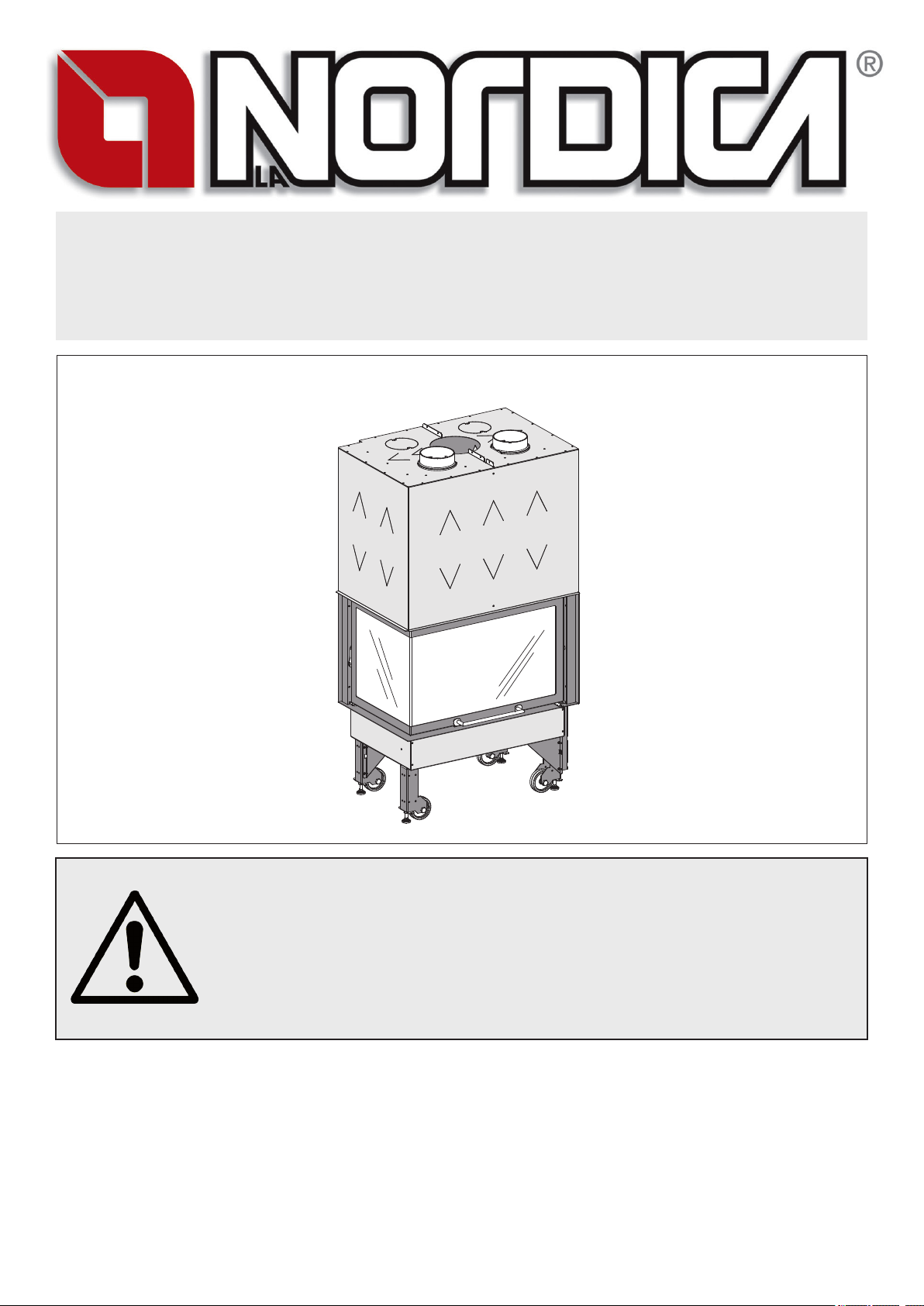
MONOBLOCCO 800 ANGOLO
Testata secondo / Tested according to / Geprüft nach / Certié selon / Probado según : EN13229
IT – PER EVITARE DANNI ALL’APPARECCHIO, RISPETTARE IL CARICO ORARIO DI COMBUSTIBILE INDICATO
NEL PRESENTE LIBRETTO.
EN – TO AVOID DAMAGES TO THE APPLIANCE, PLEASE RESPECT THE MAX. FUEL QUANTITY (KG/HR)
INDICATED IN THE USER’S MANUAL.
DE – UM SCHÄDEN AN DEM GERÄT ZU VERMEIDEN, BITTE BEACHTEN SIE DIE BRENNSTOFFMENGE (KG/H)
LT. BEDIENUNGSANLEITUNG.
FR – POUR EVITER DES DOMMAGES A L’APPAREIL RESPECTER LA QUANTITE’ MAX. DE COMBUSTIBLE (KG/H)
COMME INDIQUE DANS LA NOTICE D’UTILISATION
ES – PARA EVITAR QUE EL APARATO SE DAÑE, RESPETE EL HORARIO DE LA CARGA DE COMBUSTIBLE
INDICADA EN EL MANUAL.
NORME DI SICUREZZA SUGLI APPARECCHI - Per il rispetto delle norme di sicurezza è obbligatorio installare e utilizzare i nostri
prodotti seguendo scrupolosamente le indicazioni fornite nel presente manuale.
SAFETY REGULATIONS ON THE APPLIANCES- To meet safety regulations, it is compulsory to install and use our products
carefully following the instructions contained in this manual.
SICHERHEITSVORSCHRIFTEN BEI DEN AUSRÜSTUNGEN - Um die Sicherheitsvorschriften zu beachten, ist es notwendig,
unsere Produkte vorsichtig nach den in diesem Handbuch enthaltenen Anweisungen zu installieren und anzuwenden.
RÉGLÉS DE SÉCURITÉ SUR LES APPAREILS - Selon les normes de sécurité sur les appareils l’acheteur et le commerçant sont
contraints de s’informer sur le fonctionnement correct sur la base des instructions d’emploi.
NORMAS DE SEGURIDAD DE LOS APARATOS - Según las normas de seguridad de los aparatos, el comprador y el comerciante
tienen la obligación de informarse sobre el correcto funcionamiento según las instrucciones de uso.
Page 2
MONOBLOCCO 800 ANGOLO
ITALIANO ...................................................................................... 4
ENGLISH .................................................................................... 15
DEUTSCH ................................................................................... 26
FRANÇAIS .................................................................................. 37
ESPAÑOL ................................................................................... 48
2 6098401
Page 3
MONOBLOCCO 800 ANGOLO
1. INSTALLAZIONE
PRIMA DELL’INSTALLAZIONE ESEGUIRE LE SEGUENTI VERIFICHE.
BEFORE THE INSTALLATION PERFORM THE FOLLOWING CHECKS.
AVANT L’INSTALLATION IL FAUT RÉALISER LES SUIVANTES VÉRIFICATIONS
.ANTES DE LA INSTALACIÓN, REALIZAR LOS CONTROLES SIGUIENTES
1. INSTALLATION
VOR DER AUFSTELLUNG FOLGENDE PRÜFUNGEN AUSFÜHREN.
1. INSTALLATION
1. L’INSTALLATION
1. LA INSTALACIÓN
6098401 3
Page 4
MONOBLOCCO 800 ANGOLO
INFORMAZIONI ALL’UTENTE SULLO SMALTIMENTO DELLE APPARECCHIATURE DA PARTE DEI PRIVATI
NEL TERRITORIO DELL’UNIONE EUROPEA
Ai sensi dell’art.13 del decreto legislativo 25 luglio 2005, n.151 «attuazione delle direttive 2011/65/CE e 2003/1 08/CE, relative
sostanze alla riduzione dell’uso di sostanze pericolose nelle apparecchiature elettriche ed elettroniche, nonché allo smaltimento dei
riuti». il simbolo del cassonetto barrato riportato sull’apparecchiatura o sulla confezione indica che il prodotto alla ne della propria
vita utile deve essere raccolto separatamente dagli altri riuti. L’utente dovrà, pertanto, conferire l’apparecchiatura giunta a ne vita agli
idonei centri di raccolta differenziata dei riuti elettronici ed elettrotecnici, oppure riconsegnarla al rivenditore al momento dell’acquisto
di una nuova apparecchiatura di tipo equivalente, in ragione di uno a uno. L’adeguata raccolta differenziata per l’awio successivo
dell’apparecchiatura e dismessa al riciclaggio, al trattamento e allo smaltimento ambientalmente compatibile, contribuisce ad evitare
possibili effetti negativi sull’ambiente e sulla salute e favorisca il reimpiego e/o riciclo dei materiali di cui è composta l’apparecchiatura.
Lo smaltimento abusivo del prodotto da parte dell’utente comporta l’applicazione delle sanzioni amministrative previste dalla normativa
vigente, di cui al digs n. 22/1997 (articolo 50 e seguenti del digs n. 22/1997).
DICHIARAZIONE DI CONFORMITA’ DEL COSTRUTTORE
Oggetto: Assenza di amianto e cadmio
Si dichiara che tutti i nostri apparecchi vengono assemblati con materiali che non presentano parti di amianto o suoi
derivati e che nel materiale d’apporto utilizzato per le saldature non è presente/utilizzato in nessuna forma il cadmio, come
previsto dalla norma di riferimento.
Oggetto: Regolamento CE n. 1935/2004
Si dichiara che in tutti gli apparecchi da noi prodotti, i materiali destinati a venire a contatto con i cibi sono adatti all’uso
alimentari, in conformità al Regolamento CE in oggetto.
ITALIANO - INDICE
1. INSTALLAZIONE ............................................................................................................................................................................. 3
2. AVVERTENZE GENERALI ............................................................................................................................................................. 5
3. NORME PER L’INSTALLAZIONE ................................................................................................................................................... 5
4. SICUREZZA ANTINCENDIO ...........................................................................................................................................................5
4.1. PRONTO INTERVENTO .................................................................................................................................................................................6
4.2. PROTEZIONI DELLE TRAVI ..........................................................................................................................................................................6
5. DESCRIZIONE ................................................................................................................................................................................6
6. CANNA FUMARIA ...........................................................................................................................................................................7
6.1. COMIGNOLO ..................................................................................................................................................................................................7
6.2. COLLEGAMENTO ALLA CANNA FUMARIA ..................................................................................................................................................7
6.3. ARIA PER LA COMBUSTIONE ......................................................................................................................................................................8
6.4. PRESA D’ARIA ESTERNA ..............................................................................................................................................................................8
7. VENTILAZIONE CAPPA O LOCALE ADIACENTE ........................................................................................................................8
8. COLLEGAMENTO E MANUTENZIONE VENTILAZIONE (OPZIONALE) .....................................................................................9
9. COMBUSTIBILI AMMESSI / NON AMMESSI .................................................................................................................................9
10. ACCENSIONE ...............................................................................................................................................................................10
10.1. ACCENSIONE a BASSE EMISSIONI ...........................................................................................................................................................10
11. FUNZIONAMENTO NORMALE .................................................................................................................................................... 11
11.1. FUNZIONAMENTO NEI PERIODI DI TRANSIZIONE ..................................................................................................................................11
12. FERMO ESTIVO ............................................................................................................................................................................ 11
13. MANUTENZIONE E CURA ............................................................................................................................................................ 11
13.1. PULIZIA VETRO ...........................................................................................................................................................................................11
13.2. PULIZIA CASSETTO CENERE ....................................................................................................................................................................12
13.3. PULIZIA CANNA FUMARIA ..........................................................................................................................................................................12
13.4. MANUTENZIONE GUIDE ESTENSIBILI ......................................................................................................................................................12
14. DETERMINAZIONE DELLA POTENZA TERMICA ....................................................................................................................... 12
15. CONDIZIONI DI GARANZIA ..........................................................................................................................................................13
16. KIT VENTILAZIONE OPZIONALE ................................................................................................................................................66
17. SCHEDA TECNICA .......................................................................................................................................................................68
18. DIMENSIONI ..................................................................................................................................................................................70
4 6098401
Page 5

MONOBLOCCO 800 ANGOLO
2. AVVERTENZE GENERALI
La responsabilità de La NORDICA S.p.A. è limitata alla fornitura dell’apparecchio.
Il suo impianto va realizzato in modo conforme alla regola dell’arte, secondo le prescrizioni delle presenti istruzioni e le regole della
professione, da personale qualicato, che agisce a nome di imprese adatte ad assumere l’intera responsabilità dell’insieme dell’impianto.
La NORDICA S.p.A. non è responsabile del prodotto modicato senza autorizzazione e tanto meno per l’uso di ricambi non
originali.
Questo apparecchio non è adatto all’uso da parte di persone (inclusi bambini) con capacità siche, sensoriali e mentali ridotte, o inesperte,
a meno che non vengano supervisionate ed istruite nell’uso dell’apparecchio da una persona responsabile per la loro sicurezza. I bambini
devono essere controllati per assicurarsi che non giochino con l’apparecchio (EN 60335-2-102 / 7.12).
E’ OBBLIGATORIO rispettare norme nazionali ed europee, disposizioni locali o in materia edilizia, nonché regolamentazioni
antincendio.
NON SI POSSONO EFFETTUARE MODIFICHE ALL’APPARECCHIO. Non vi sarà responsabilità da parte de La NORDICA S.p.A. in
caso di mancato rispetto di tali precauzioni.
3. NORME PER L’INSTALLAZIONE
L’installazione del prodotto e degli equipaggiamenti ausiliari, relativi all’impianto di riscaldamento, deve essere conforme a tutte le Norme
e Regolamentazioni attuali ed a quanto previsto dalla Legge.
L’installazione, i relativi collegamenti dell’impianto, la messa in servizio e la verica del corretto funzionamento devono essere eseguiti
a regola d’arte da personale professionalmente preparato nel pieno rispetto delle norme vigenti, sia nazionali, regionali, provinciali e
comunali presenti nel paese in cui è stato installato l’apparecchio, nonché delle presenti istruzioni.
L’installazione deve essere eseguita da personale autorizzato, che dovrà rilasciare all’acquirente una dichiarazione di conformità
dell’impianto, il quale si assumerà l’intera responsabilità dell’installazione denitiva e del conseguente buon funzionamento del prodotto
installato.
Prima dell’installazione eseguire le seguenti veriche:
• Accertarsi che il pavimento possa sostenere il peso dell’apparecchio e provvedere ad un adeguato isolamento nel caso sia costruito
in materiale inammabile (DIMENSIONI SECONDO L’ORDINAMENTO REGIONALE).
• Assicurarsi che nella stanza dove sarà installato vi sia una ventilazione adeguata.
• Evitare l’installazione in locali con presenza di condotti di ventilazione collettivo, cappe con o senza estrattore, apparecchi a gas
di tipo B, pompe di calore o la presenza di apparecchi il cui funzionamento contemporaneo possa mettere in depressione il locale
(rif. Norma UNI 10683)
• Accertarsi che la canna fumaria e i tubi a cui verrà collegato l’apparecchio siano idonei, NON è consentito il collegamento di più
apparecchi allo stesso camino.
• Il diametro dell’apertura per il collegamento al camino deve corrispondere per lo meno al diametro del tubo fumo. L’apertura
dovrebbe essere dotata di una connessione a muro per l’inserimento del tubo di scarico e di un rosone.
• Lasciare sempre un minimo di vuoto d’aria tra il prodotto e le pareti, laterale e posteriore (vedi INFORMAZIONI MARCATURA CE).
• Stabilire il tipo di ventilazione (naturale o forzata) vedi capitolo VENTILAZIONE CAPPA O LOCALE ADIACENTE.
• Tramite i piedini regolabili e mediante l’impiego di una livella assicurarsi che l’apparecchio sia perfettamente in piano per permettere
un corretto scorrimento della porta.
Dopo un po’ di
procedere alla costruzione del rivestimento estetico.
AVVERTENZA: Nel costruire il rivestimento, bisogna tenere presente delle eventuali, e successive, manutenzioni agli organi elettrici
installati (p.e. ventilatori, sonda di temperatura, etc.) e dove presente l’impianto idraulico, ai dispositivi connessi al prodotto.
La NORDICA S.p.A. declina ogni responsabilità per danni a cose e/o persone provocati dall’impianto. Inoltre non è responsabile
del prodotto modicato senza autorizzazione e tanto meno per l’uso di ricambi non originali.
Il Vostro abituale spazzacamino di zona deve essere informato sull’installazione del prodotto, afnché possa vericarne il regolare
collegamento alla canna fumaria ed il grado di efcienza di quest’ultima.
giorni di funzionamento (il tempo necessario per stabilire che l’apparecchio funziona correttamente) si può
4. SICUREZZA ANTINCENDIO
Nell’installazione dell’apparecchio devono essere osservate le seguenti misure di sicurezza:
a) Al ne di assicurare un sufciente isolamento termico, rispettare la distanza minima di sicurezza dal retro e da entrambi i lati da
elementi costruttivi ed oggetti inammabili e sensibili al calore (vedi INFORMAZIONI MARCATURA CE - Figura 7 a pagina 62). Tutte
le distanze minime di sicurezza sono indicate sulla targhetta tecnica del prodotto e NON si deve scendere al di sotto dei
valori indicati;
b) Davanti alla porta del focolare, nell’area di radiazione della stessa, non deve esserci alcun oggetto o materiale di costruzione
inammabile e sensibile al calore a meno di 80 cm di distanza. Tale distanza può essere ridotta a 40 cm qualora venga installata
una protezione, retroventilata e resistente al calore, davanti all’intero componente da proteggere;
c) Qualora il prodotto sia installato su un pavimento di materiale inammabile, bisogna prevedere un sottofondo ignifugo. I pavimenti
in materiale inammabile, come moquette, parquet o sughero etc., devono essere coperti da uno strato di materiale non
inammabile (dimensioni secondo l’ordinamento regionale) vedi Figura 1 a pagina 59.
6098401 5
Page 6
MONOBLOCCO 800 ANGOLO
Il prodotto deve funzionare esclusivamente con il cassetto cenere inserito.
I residui solidi della combustione (ceneri) devono essere raccolti in un contenitore ermetico e resistente al fuoco. L’apparecchio non deve
mai essere acceso in presenza di emissioni gassose o vapori (per esempio colla per linoleum, benzina ecc.). Non depositate materiali
inammabili nelle vicinanze dell’apparecchio.
Durante la combustione viene sprigionata energia termica che comporta un marcato riscaldamento delle superci, della porta e del vetro
del focolare, delle maniglie delle porte o di comando, del tubo fumi ed eventualmente della parte anteriore dell’apparecchio. Evitate il
contatto con tali elementi senza un corrispondente abbigliamento protettivo o senza utensili accessori (guanti resistenti al calore,
dispositivi di comando).
Fate in modo che i bambini siano consapevoli di questi pericoli e teneteli lontani dal focolare durante il suo funzionamento.
Avvertire i bambini che l’apparecchio diventa molto caldo e che non deve essere toccato.
Quando si utilizza un combustibile errato o troppo umido si formano dei depositi (creosoto) nella canna fumaria con il rischio d’incendio.
4.1. PRONTO INTERVENTO
Se si manifesta un incendio nel camino o nella canna fumaria:
a) Chiudere la porta di caricamento.
b) Chiudere i registri dell’aria comburente
c) Spegnere tramite l’uso di estintori ad anidride carbonica (CO2 a polveri )
d) Richiedere l’immediato intervento dei VIGILI del FUOCO
NON SPEGNERE IL FUOCO CON L’USO DI GETTI D’ACQUA.
Quando la canna fumaria smette di bruciare, bisogna farla vericare da uno specialista per individuare eventuali crepe o punti permeabili.
4.2. PROTEZIONI DELLE TRAVI
Tenendo conto dell’irradiazione del focolare, dovete essere particolarmente attenti alla protezione delle travi nella progettazione del vostro
camino, tenete conto da una parte della prossimità della trave dalle facce esterne del focolare, e dall’altra dell’irradiazione della porta
in vetro che normalmente è molto vicina alle travi stesse. Sappiate che in qualsiasi caso, le facce interne o inferiori di questa trave in
materiale combustibile non devono essere in contatto con temperature superiori ai 65 °C.
In Figura 2 a pagina 59 sono riportati alcuni esempi di soluzione.
AVVERTENZA: Non potremo essere ritenuti responsabili per un cattivo funzionamento dell’impianto non conforme alle
prescrizioni delle presenti istruzioni o ancora dall’uso di prodotti complementari non adatti.
5. DESCRIZIONE
Denizione secondo la Norma EN13229 : questo è un apparecchio a combustione intermittente.
L’apparecchio è composto da lastre in lamiera d’acciaio verniciato, fusioni di ghisa e materiali refrattari.
Il focolare è rivestito da fusioni di ghisa e da lastre in refrattario, il portagriglia e la relativa griglia estraibile sono entrambi in ghisa. L’insieme
della camera di combustione è a tenuta ermetica mediante saldatura e rivestito con un carter in lamiera zincata.
Gli apparecchi 800 dispongono di un focolare con schiena a doppio spessore, composto da una piastra estraibile forata.
Attraverso questi fori arriva all’interno del focolare dell’ aria preriscaldata, si ottiene così una post-combustione con un aumento del
rendimento ed una riduzione di emissioni dei gas incombusti.
La porta panoramica è montata su guide estensibili a sfere le quali garantiscono un funzionamento robusto, silenzioso ed afdabile nel
tempo. Il contrappeso di sollevamento della porta è sostenuto da due robuste catene con relativi pignoni.
Il vetro ceramico (resistente no 700 C) della porta, consente un’affascinante vista sulle amme ardenti ed impedisce ogni fuoriuscita di
scintille e fumo.
Il riscaldamento dell’ambiente avviene:
• Per convezione: il passaggio dell’aria attraverso il mantello e la cappa di rivestimento rilascia calore nell’ambiente.
• Per radiazione: attraverso il vetro panoramico e il corpo in acciaio viene irraggiato calore nell’ambiente.
L’apparecchio è dotato di registri per l’aria primaria e secondaria, con i quali viene regolata la combustione.
1A- Registro aria PRIMARIA (Figura 8 a pagina 63)
Con il registro posto sotto la porta del focolare viene regolato il passaggio dell’aria attraverso il cassetto cenere e la griglia in direzione
del combustibile. L’aria primaria è necessaria per il processo di combustione.
• Nel modello 800 bisogna estrarre (tirare) totalmente la leva.
Il cassetto cenere deve essere svuotato regolarmente, in modo che la cenere non possa ostacolare l’entrata d’aria primaria per la
combustione. Attraverso l’aria primaria viene anche mantenuto vivo il fuoco.
Durante la combustione di legna, il registro d’aria primaria deve essere aperto solo un poco, poiché altrimenti la legna arde velocemente
e l’apparecchio si può surriscaldare (vedi paragrafo FUNZIONAMENTO).
2A - Registro aria SECONDARIA (Figura 8 a pagina 63)
L’aria secondaria, passando internamente ai due montanti laterali della facciata, si riscalda ed innesca la doppia combustione
mantenendo, nello stesso tempo, il vetro della porta pulito (registro totalmente a destra). Con la leva del registro posta centralmente,
l’apparecchio (mod. 800) funziona a regime ridotto, e cioè: l’aria primaria è chiusa e l’aria secondaria è dimezzata (vedi paragrafo
FUNZIONAMENTO).
6 6098401
Page 7

MONOBLOCCO 800 ANGOLO
La regolazione dei registri necessaria per l’ottenimento della resa calorica nominale è la seguente:
Combustibile Aria PRIMARIA Aria SECONDARIA Aria TERZIARIA
MONOBLOCCO 800 Legna APERTA APERTA PRETARATA
ACCESSORI GRASSO per alta
temperatura
MONOBLOCCO 800 DI SERIE DI SERIE DI SERIE
ATTIZZATOIO GUANTO
6. CANNA FUMARIA
Requisiti fondamentali per un corretto funzionamento dell’apparecchio:
• la sezione interna deve essere preferibilmente circolare;
• essere termicamente isolata ed impermeabile e costruita con materiali idonei a resistere al calore, ai prodotti della
combustione ed alle eventuali condense;
• essere priva di strozzature ed avere andamento verticale con deviazioni non superiori a 45°;
• se già usata deve essere pulita;
• rispettare i dati tecnici del manuale di istruzioni;
Qualora le canne fumarie fossero a sezione quadrata o rettangolare gli spigoli interni devono essere arrotondati con raggio non inferiore
a 20 mm. Per la sezione rettangolare il rapporto massimo tra i lati deve essere = 1,5.
Una sezione troppo piccola provoca una diminuzione del tiraggio. Si consiglia un’altezza minima di 4 m.
Sono vietate e pertanto pregiudicano il buon funzionamento dell’apparecchio: brocemento, acciaio zincato,superci interne ruvide e
porose. In Figura 3 a pagina 59 sono riportati alcuni esempi di soluzione.
La sezione minima deve essere di 4 dm2 (per esempio 20 x 20 cm) per gli apparecchi il cui diametro di condotto è inferiore a 200
mm, o 6,25 dm2 (per esempio 25 x 25 cm) per gli apparecchi con diametro superiore a 200 mm.
Il tiraggio creato dalla vostra canna fumaria deve essere sufciente ma non eccessivo.
Una sezione della canna fumaria troppo importante può presentare un volume troppo grande da riscaldare e dunque provocare delle
difcoltà di funzionamento dell’apparecchio; per evitare ciò provvedete ad intubare la stessa per tutta la sua altezza. Una sezione troppo
piccola provoca una diminuzione del tiraggio.
ATTENZIONE: per quanto riguarda la realizzazione del collegamento alla canna fumaria e i materiali inammabili attenersi a quanto
previsto dalla Norma UNI10683. La canna fumaria deve essere adeguatamente distanziata da materiali inammabili o combustibili
mediante un opportuno isolamento o un’intercapedine d’aria.
E’ VIETATO far transitare all’interno della stessa tubazioni di impianti o canali di adduzione d’aria. E’ proibito inoltre praticare aperture
mobili o sse ,sulla stessa, per il collegamento di ulteriori apparecchi diversi (Figura 4 a pagina 60).
6.1. COMIGNOLO
Il tiraggio della canna fumaria dipende anche dall’idoneità del comignolo.
È pertanto indispensabile che, se costruito artigianalmente, la sezione di uscita sia più di due volte la sezione interna della
canna fumaria. Dovendo sempre superare il colmo del tetto, il comignolo dovrà assicurare lo scarico anche in presenza di vento
(Figura 5 a pagina 60 - Figura 6 a pagina 61).
Il comignolo deve rispondere ai seguenti requisiti:
• avere sezione interna equivalente a quella del camino.
• avere sezione utile d’uscita doppia di quella interna della canna fumaria.
• essere costruito in modo da impedire la penetrazione nella canna fumaria di pioggia, neve e di qualsiasi corpo estraneo.
• essere facilmente ispezionabile, per eventuali operazioni di manutenzione e pulizia.
6.2. COLLEGAMENTO ALLA CANNA FUMARIA
Il collegamento al camino deve essere eseguito con tubi rigidi in acciaio conforme a tutte le Norme e Regolamentazioni attuali ed a quanto
previsto dalla Legge.
È VIETATO l’uso di tubi essibili metallici o in brocemento poiché pregiudicano la sicurezza del raccordo stesso in quanto sono
soggetti a strappi o rotture causando perdite di fumo.
Il tubo di scarico fumi deve essere ssato ermeticamente al camino e può avere un’inclinazione massima di 45°, questo per evitare depositi
eccessivi di condensa prodotta nelle fasi iniziali d’accensione e/o l’aggrappaggio eccessivo di fuliggine ed inoltre evita il rallentamento dei
fumi in uscita.
La non ermeticità del collegamento può causare il malfunzionamento dell’apparecchio.
Il diametro interno del tubo di collegamento deve corrispondere al diametro esterno del tronchetto di scarico fumi dell’apparecchio. Ciò
viene garantito dai tubi secondo DIN 1298.
Per un migliore funzionamento dell’apparecchio, viene consigliata una depressione al camino di 17-20 Pascal (=1.7-2 mm di
colonna d’acqua).
La misurazione deve essere fatta sempre ad apparecchio caldo (resa calorica nominale).
Quando la depressione supera 20 Pa (=2 mm di colonna d’acqua) è necessario ridurla con l’installazione di un regolatore di tiraggio
supplementare (valvola a farfalla) sul tubo di scarico o nel camino, come da normative vigenti.
IMPORTANTE: Con l’utilizzo di tubi metallici è indispensabile che questi siano isolati con materiali idonei (rivestimenti in bra
isolante resistente no a 600° C) al ne di evitare deterioramenti delle murature o della contro cappa.
6098401 7
Page 8
MONOBLOCCO 800 ANGOLO
6.3. ARIA PER LA COMBUSTIONE
E’ indispensabile che lo spazio compreso tra la parte superiore, i lati dell’apparecchio ed il deettore di materiale incombustibile della
cappa, sia costantemente ventilato.
Bisogna per questo motivo consentire un’entrata di aria dal basso (entrata di aria fresca) ed un’uscita alta (uscita d’aria calda). Gli
spazi previsti per la circolazione dell’aria indicati nelle gure ( Figura 7 a pagina 62 - Figura 14 a pagina 64) sono i requisiti minimi:
Sommità
: apertura minima: 1000 cm
Base: apertura minima: 750 cm
2
2
Si otterrà quindi:
• una maggiore sicurezza
• un aumento del calore creato dalla circolazione d’aria attorno all’apparecchio
• un migliore funzionamento dell’apparecchio
La griglia di sato calore (Figura 7 a pagina 62 pos. 6 ) va installata sulla parte superiore della cappa a circa 20 cm dal softto. Questa
deve sempre essere installata in quanto la sua funzione è quella di lasciare fuoriuscire nel locale il calore accumulato all’interno della
cappa (sovrapressione).
ATTENZIONE si consiglia la realizzazione della contro cappa in cartongesso ignifugo con telaio metallico autoportante, in maniera da non
far gravare il suo peso sul rivestimento estetico stesso (marmo). Si consiglia di predisporre una porta di ispezione sulla contro cappa
o dove ritenuto opportuno per una agevole accessibilità e visibilità dei dispositivi di sicurezza (manometri, valvole, circolatore,..).
6.4. PRESA D’ARIA ESTERNA
Per un buon funzionamento dell’apparecchio è OBBLIGATORIO che nel luogo d’installazione venga immessa sufciente aria per la
combustione e la riossigenazione dell’ambiente stesso. Ciò signica che, attraverso apposite aperture comunicanti con l’esterno, deve
poter circolare aria per la combustione anche a porte e nestre chiuse.
• La presa d’aria deve essere posizionata in modo da non poter essere ostruita;
• La presa d’aria deve essere comunicante con il locale d’installazione dell’apparecchio ed essere protetta con una griglia.
• Qualora l’afusso d’aria fosse ottenuto attraverso aperture comunicanti con locali adiacenti, sono da evitare (VIETATO) prese d’aria
in collegamento con garage, cucine, bagni, centrali termiche.
• Se nel locale di installazione dell’apparecchio fossero presenti delle cappe di aspirazione, queste NON devono essere fatte
funzionare contemporaneamente. Queste, infatti, possono provocare l’uscita di fumi nel locale, anche con la porta del focolare
chiusa.
Dimensioni minime (Figura 15 a pagina 65):
A – convenzione naturale
: 300 cm
2
B – convenzione forzata: 150 cm2 presa aria esterna per l’apparecchio, dove presente (*B1);
2
150 cm
150 cm
presa aria esterna per il ventilatore, dove presente (B2);
2
presa aria interna per il ventilatore, dove presente (C ).
* (Per un miglior benessere e relativa ossigenazione dell’ambiente, l’aria di combustione può essere prelevata direttamente dall’esterno
da un raccordo (B1) di collegamento ad un tubo essibile (NON fornito) per l’aria comburente esterna. Il tubo di collegamento deve essere
liscio con un diametro minimo di (B1 Figura 15 a pagina 65) , dovrà avere una lunghezza massima di 4 m e presentare non più di tre curve.
Qualora questo sia collegato direttamente con l’esterno deve essere dotato di un apposito frangivento).
IMPORTANTE: se non si adotta la soluzione 1, si è OBBLIGATI ad adottare la soluzione 2. In caso contrario, mancando l’apporto
di aria comburente, il prodotto non funziona!
7. VENTILAZIONE CAPPA O LOCALE ADIACENTE
Il prodotto può distribuire l’aria riscaldata tramite convenzione naturale o tramite convenzione forzata mediante l’uso di un ventilatore
centrifugo (vedi capitolo KIT di ventilazione OPZIONALE), pertanto in fase di installazione bisogna decidere il tipo di ventilazione o
convezione da adottare:
A ) CONVEZIONE NATURALE:
Per favorire la circolazione naturale dell’aria (movimento ascensionale dovuto al riscaldamento della stessa) bisogna togliere i semitranci
dall’involucro esterno del prodotto (Figura 11 a pagina 64).
Scegliendo questo sistema di convezione è sconsigliata la successiva installazione dell’elettroventilatore.
B ) CONVENZIONE FORZATA:
Tramite l’installazione di un ventilatore centrifugo è possibile distribuire l’aria calda nei locali adiacenti tramite canalizzazioni no a 4 metri
di lunghezza. In questo caso non rimuovere i semitranci dall’involucro esterno del prodotto (Figura 11 a pagina 64).
La copertura di ogni prodotto è dotata di 2 uscite con diametro di 150 mm (15 cm) per il collegamento di tubi resistenti al calore.
a) Eseguire la foratura sui muri o sulla cappa esistente per permettere il passaggio e l’applicazione dei tubi essibili (ignifughi) di
diametro 15 cm con le relative bocchette;
b) ssare i tubi tramite delle fascette ai relativi collari e bocchette; dopo aver tolto i tappi semitrancio;
c) ogni tubo non dovrà superare i 2 metri di lunghezza per la ventilazione naturale e i 4 metri per la ventilazione forzata, dovrà essere
coibentato con materiali isolanti per evitare rumorosità e dispersione di calore;
8 6098401
Page 9
MONOBLOCCO 800 ANGOLO
d) le bocchette vanno posizionate ad una altezza non inferiore ai 2 m dal pavimento per evitare che l’aria calda in uscita investa le
persone; rispettare la distanza delle aperture di convenzione secondo le normative costruttive locali;
e) le lunghezze dei tubi di canalizzazione dovranno essere di uguale lunghezza per evitare diverse quantità d’aria distribuita da ogni
uscita (Figura 12 a pagina 64).
8. COLLEGAMENTO E MANUTENZIONE VENTILAZIONE (OPZIONALE)
La centralina e l’impianto dovranno essere installate e collegate da personale abilitato secondo le norme vigenti (vedi capitolo
AVVERTENZE GENERALI).
ATTENZIONE: La centralina e il cavo di alimentazione NON deve essere a contatto con parti calde.
Sui nostri prodotti possono essere installati dei kit di ventilazione OPZIONALI adatti a migliorare la distribuzione del calore attraverso la
ventilazione del solo ambiente di installazione oppure del locale adiacente (vedi capitolo PRESA ARIA ESTERNA).
Per l’installazione del Kit di ventilazione forzata seguire le istruzioni indicate (vedi capitolo VENTILAZIONE CAPPA O LOCALE
ADIACENTE). Il Kit è
avviare il ventilatore quando l’apparecchio è adeguatamente riscaldato e lo arresta quando è parzialmente freddo.
L’accensione e la regolazione viene effettuata tramite l’apposita centralina in dotazione la quale dovrà essere installata lontana da fonti di
calore dirette.
COLLEGAMENTO (vedi capitolo KIT VENTILAZIONE OPTIONALE):
Collegare il cavo di alimentazione della centralina ad un interruttore bipolare con distanza tra i contatti di almeno 3 mm (Alimentazione
230V~ 50 Hz, indispensabile il corretto collegamento all’impianto di messa a terra).
AVVERTENZA: Il COMANDO deve essere alimentato in rete con a monte un interruttore generale differenziale di linea come dalle vigenti
normative. Il corretto funzionamento del comando è garantito solamente per l’apposito motore per il quale è stato costruito. L’uso improprio
solleva il costruttore da ogni responsabilità.
composto da
un ventilatore centrifugo, una centralina di accensione e regolazione e da un termostato (TM) che fa
9. COMBUSTIBILI AMMESSI / NON AMMESSI
I combustibili ammessi sono ceppi di legna. Si devono utilizzare esclusivamente ceppi di legna secca (contenuto d’acqua max. 20%).
Si dovrebbero caricare al massimo 2 o 3 ceppi di legna. I pezzi di legna dovrebbero avere una lunghezza di ca. 20-30 cm ed una
circonferenza di massimo 30-35 cm.
I tronchetti di legno pressati non resinati devono essere usati con cautela per evitare surriscaldamenti dannosi all’apparecchio,
in quanto questi hanno un potere calorico elevato.
La legna usata come combustibile deve avere un contenuto d’umidità inferiore al 20% e deve essere deposta in luogo asciutto. La
legna umida rende l’accensione più difcile, poiché è necessaria una maggiore quantità d’energia per far evaporare l’acqua presente.
Il contenuto umido ha inoltre lo svantaggio che, con l’abbassarsi della temperatura, l’acqua si condensa prima nel focolare e quindi nel
camino causando un notevole deposito di fuliggine con successivo possibile rischio d’incendio della stessa.
La legna fresca contiene circa il 60% di H2O, perciò non è adatta ad essere bruciata. Bisogna collocarla in luogo asciutto e ventilato (per
esempio sotto una tettoia) per almeno due anni prima di utilizzarla.
Tra gli altri NON possono essere bruciati: carbone, ritagli, cascami di corteccia e pannelli, legna umida o trattata con vernici,
materiali di plastica; in tal caso decade la garanzia sull’apparecchio.
Carta e cartone devono essere utilizzati solo per l’accensione.
La combustione di riuti è VIETATA e danneggerebbe inoltre l’apparecchio e la canna fumaria, provocando inoltre danni alla salute ed
in virtù del disturbo olfattivo a reclami da parte del vicinato .
La legna non è un combustibile a lunga durata e pertanto non è possibile un riscaldamento continuo durante la notte.
Specie kg/mc kWh/kg Umidità 20%
Faggio 750 4,0
Cerro 900 4,2
Olmo 640 4,1
Pioppo 470 4,1
Larice* 660 4,4
Abete rosso* 450 4,5
Pino silvestre* 550 4,4
* LEGNI RESINOSI POCO ADATTI
ATTENZIONE: L’uso continuo e prolungato di legna particolarmente ricca di oli aromatici (p.e. Eucalipto, Mirto, etc.) provoca il
deterioramento (sfaldamento) repentino dei componenti in ghisa presenti nel prodotto.
I dati tecnici dichiarati sono stati ottenuti utilizzando essenza di faggio di classe “A1” come da normativa UNI EN ISO 17225-5 e umidità
inferiore al 20%. L’utilizzo di altre essenze potrebbe comportare la necessità di regolazioni speciche e potrebbe far ottenere rese diverse
dal prodotto.
6098401 9
Page 10
MONOBLOCCO 800 ANGOLO
10. ACCENSIONE
Alla prima accensione è inevitabile che venga prodotto un odore sgradevole (dovuto dall’essiccamento dei collanti presenti nella cordicella
di guarnizione o dalle vernici protettive), il quale sparisce dopo un breve utilizzo del prodotto. Si deve comunque assicurare una buona
ventilazione dell’ambiente.
Per accendere il fuoco consigliamo di usare piccoli listelli di legno con carta oppure altri mezzi di accensione in commercio.
È VIETATO l’uso di tutte le sostanze liquide come per es. alcool, benzina, petrolio e simili.
Aprire totalmente l’aria primaria.
Quando la legna comincia ad ardere si può ricaricare aprendo lentamente la porta, in modo da evitare fuori uscite di fumo, si chiude il
registro dell’aria primaria e si controlla la combustione mediante l’aria secondaria secondo le indicazioni del CAP. DESCIZIONE TECNICA.
Durante questa fase, non lasciare mai il focolare senza supervisione.
Mai sovraccaricare l’apparecchio (consultare la tabella tecnica - quantità max. di combustibile caricabile / consumo orario.
Troppo combustibile e troppa aria per la combustione possono causare surriscaldamento e quindi danneggiare lo stesso.
Non accendere mai l’apparecchio quando ci sono gas combustibili nella stanza.
Per una corretta prima accensione dei prodotti trattati con vernici per alte temperature, occorre sapere quanto segue:
• i materiali di costruzione dei prodotti in questione non sono omogenei, infatti coesistono parti in ghisa e in acciaio.
• la temperatura alla quale il corpo del prodotto è sottoposto non è omogenea: da zona a zona si registrano temperature variabili dai
300 °C ai 500 °C;
• durante la sua vita, il prodotto è sottoposto a cicli alternati di accensioni e di spegnimento durante la stessa giornata e a cicli di
intenso utilizzo o di assoluto riposo al variare delle stagioni;
• prima di potersi denire rodato, il prodotto nuovo dovrà essere sottoposto a diversi cicli di avviamento per poter consentire a tutti i
materiali ed alla vernice di completare le varie sollecitazioni elastiche;
• in particolare inizialmente si potrà notare l’emissione di odori tipici dei metalli sottoposti a grande sollecitazione termica e di vernice
ancora fresca. Tale vernice, sebbene in fase di costruzione venga cotta a 250°C per qualche ora, dovrà superare più volte e per
una certa durata la temperatura di 350°C, prima di incorporarsi perfettamente con le superci metalliche
Diventa quindi importante seguire questi piccoli accorgimenti in fase di accensione:
1. Assicuratevi che sia garantito un forte ricambio d'aria nel luogo dove è installato l'apparecchio.
2. Nelle prime accensioni, non caricare eccessivamente la camera di combustione (circa metà della quantità indicata nel manuale
d'istruzioni) e tenere il prodotto acceso per almeno 6-10 ore di continuo, con i registri meno aperti di quanto indicato nel manuale
d'istruzioni.
3. Ripetere questa operazione per almeno 4-5 o più volte, secondo la Vostra disponibilità.
4. Successivamente caricare sempre più (seguendo comunque quanto descritto sul libretto di istruzione relativamente al massimo
carico) e tenere possibilmente lunghi i periodi di accensione evitando, almeno in questa fase iniziale, cicli di accensione-spegnimento
di breve durata.
5. Durante le prime accessioni nessun oggetto dovrebbe essere appoggiato sull’apparecchio ed in particolare sulle superci
laccate. Le superci laccate non devono essere toccate durante il riscaldamento.
6. Una volta superato il “rodaggio” si potrà utilizzare il Vostro prodotto come il motore di un’auto, evitando bruschi riscaldamenti con
eccessivi carichi.
Dopo un po’ di giorni di funzionamento (il tempo necessario per stabilire che l’apparecchio funziona correttamente) si può
procedere alla costruzione del rivestimento estetico.
ATTENZIONE: nel costruire il rivestimento, bisogna tenere presente delle eventuali, e successive, manutenzioni agli organi elettrici
installati (p.e. ventilatori, sonda di temperatura, etc.) e dove presente l’impianto idraulico, ai dispositivi connessi al termoprodotto.
10.1. ACCENSIONE a BASSE EMISSIONI
La combustione senza fumo è un metodo di accensione per ridurre in modo signicativo le emissioni di sostanze nocive. La legna brucia
gradualmente dall’alto verso il basso, così la combustione procede più lentamente ed in modo più controllato. I gas combusti, passando
attraverso le alte temperature della amma, bruciano quasi completamente.
Mettere i ciocchi di legna nel focolare ad una certa distanza uno dall’altro, come indicato in Figura 16 a pagina 65. Disporre in basso i più
grossi e in alto i più ni, o in verticale nel caso di camere di combustione strette e alte. Collocare il modulo di accensione sopra alla catasta,
disporre i primi ciocchi del modulo perpendicolarmente alla catasta di legna.
Modulo di accensione. Questo modulo di accensione sostituisce quello di carta o cartone.
Preparare 4 ciocchi con una sezione trasversale di 3cm x 3cm e una lunghezza di 20 cm Figura 16 a pagina 65. Mettere i quattro ciocchi
incrociati sopra la catasta di legna, trasversalmente ad essa, con nel mezzo del modulo l’accendi fuoco, che può essere per esempio lana
di legna impregnata di cera. Un ammifero è sufciente per accendere il fuoco. Volendo si possono utilizzare anche pezzi di legno più
sottili: in tal caso ne occorrerà una maggiore quantità.
Tenere aperte la valvola di scarico fumi e il registro per l’aria comburente (1A - 2A). Dopo avere acceso il fuoco, lasciare il registro che
regola l’aria per la combustione nella posizione indicata in Figura 16 a pagina 65.
IMPORTANTE:
• non aggiungere ulteriore legna tra una carica completa e l’altra;
• non soffocare il fuoco chiudendo le prese d’aria;
• la pulizia regolare da parte di uno spazzacamino riduce le emissioni di polveri sottili.
Queste indicazioni sono sostenute da ENERGIA Legno SVIZZERA www.energia-legno.ch
10 6098401
Page 11

MONOBLOCCO 800 ANGOLO
11. FUNZIONAMENTO NORMALE
Dopo aver posizionato i registri correttamente, inserire la carica di legna oraria indicata evitare sovraccarichi che provocano sollecitazioni
anomale e deformazioni. Bisogna sempre usare il prodotto con la porta chiusa per evitare danneggiamenti dovuti all’eccessivo
surriscaldamento (effetto forgia) in caso contrario, decade la garanzia.
Con i registri posti sulla facciata dell’apparecchio viene regolata l’emissione di calore dello stesso. Essi devono essere aperti secondo il
bisogno calorico. La migliore combustione (con emissioni minime) viene raggiunta quando, caricando legna, la maggior parte dell’aria per
la combustione passa attraverso il registro dell’aria secondaria.
Non si deve mai sovraccaricare l’apparecchio. Troppo combustibile e troppa aria per la combustione possono causare
surriscaldamento e quindi danneggiare il focolare. I danni causati da surriscaldamento non sono coperti da garanzia.
Bisogna pertanto usare il prodotto sempre con la porta chiusa per evitare danneggiamenti dovuti all’eccessivo surriscaldamento (effetto
forgia).
La regolazione dei registri necessaria per l’ottenimento della resa calorica nominale con una depressione al camino di 12 Pa (=1.2 mm
di colonna d’acqua) è la seguente: vedi capitolo DESCRIZIONE TECNICA. Questo è un apparecchio a combustione intermittente.
Oltre che dalla regolazione dell’aria per la combustione, l’intensità della combustione e quindi la resa calorica del vostro apparecchio è
inuenzata dal camino. Un buon tiraggio del camino richiede una regolazione più ridotta dell’aria per la combustione, mentre uno scarso
tiraggio necessita maggiormente di un’esatta regolazione dell’aria per la combustione.
Per vericare la buona combustione, controllate se il fumo che esce dal camino è trasparente. Se è bianco signica che l’apparecchio non
è regolato correttamente o la legna è troppo bagnata; se invece il fumo è grigio o nero è segno che la combustione non è completa (è
necessaria una maggior quantità di aria secondaria).
ATTENZIONE: Quando si aggiunge combustibile sopra alle braci in assenza di amma si potrebbe vericare un elevato sviluppo di fumi.
Se questo dovesse avvenire si potrebbe formare una miscela esplosiva di gas e aria e, in casi estremi vericare un’esplosione. Per
motivi di sicurezza si consiglia di eseguire una nuova procedura di accensione con utilizzo di piccoli listelli.
11.1. FUNZIONAMENTO NEI PERIODI DI TRANSIZIONE
Durante il periodo di transizione, ovvero quando le temperature esterne sono più elevate, in caso di improvviso aumento della temperatura
si possono avere dei disturbi alla canna fumaria che fanno si che i gas combusti non vengono aspirati completamente. I gas di scarico non
fuoriescono più completamente (odore intenso di gas).
In tal caso scuotete più frequentemente la griglia e aumentate l’aria per la combustione. Caricate in seguito una quantità ridotta di
combustibile facendo sì che questo bruci più rapidamente ( con sviluppo di amme ) e si stabilizzi così il tiraggio della canna fumaria.
Controllate quindi che tutte le aperture per la pulizia e i collegamenti al camino siano ermetici. In caso di incertezza rinunciate all’utilizzo
dell’apparecchio.
12. FERMO ESTIVO
Dopo aver effettuato la pulizia del focolare, del camino e della canna fumaria, provvedendo all’eliminazione totale della cenere ed altri
eventuali residui, è opportuno chiudere tutte le porte con i relativi registri focolare. Nel caso in cui l’apparecchio venga disconnesso dal
camino, è opportuno chiudere il foro di uscita.
E’ consigliabile effettuare l’operazione di pulizia della canna fumaria almeno una volta all’anno; vericando nel contempo l’effettivo stato
delle guarnizioni che se non risultassero perfettamente integre - cioè non più aderenti alla stufa - non garantirebbero il buon funzionamento
dell’apparecchio! Si renderebbe quindi necessaria la loro sostituzione.
In caso di umidità del locale dove è posto l’apparecchio, sistemare dei sali assorbenti all’interno del focolare.
Proteggere le parti in ghisa, se si vuole mantenere inalterato nel tempo l’aspetto estetico, con della vaselina neutra.
13. MANUTENZIONE E CURA
Controllare e pulire, almeno una volta all’anno, la presa d’aria esterna. Il camino deve essere regolarmente ramazzato dallo spazzacamino.
Fate controllare dal Vostro spazzacamino responsabile di zona la regolare installazione del prodotto, il collegamento al camino e l’aerazione.
IMPORTANTE: La manutenzione deve essere eseguita esclusivamente ad apparecchio freddo..Si possono usare esclusivamente
parti di ricambio espressamente autorizzate ed offerte da La NORDICA S.p.A.. In caso di bisogno Vi preghiamo di rivolgerVi al Vs
rivenditore specializzato. L’ APPARECCHIO NON PUÒ ESSERE MODIFICATO!
13.1. PULIZIA VETRO
Dopo aver vericato che la porta sia totalmente abbassata, sbloccare il chiavistello superiore (Figura 9 a pagina 63 pos.A) aprirla a ribalta,
pulire il vetro, chiudere la ribalta e bloccare il chiavistello prima di risollevare la porta.
Tramite uno specico ingresso dell’aria secondaria la formazione di deposito di sporco, sul vetro della porta, viene efcacemente rallentata.
Non può comunque mai essere evitata con l’utilizzo dei combustibili solidi (es. legna umida ) e questo non è da considerarsi come un
difetto dell’apparecchio .
IMPORTANTE: la pulizia del vetro panoramico deve essere eseguita solo ed esclusivamente a apparecchio freddo per evitarne
l’esplosione. Per la pulizia si possono usare dei prodotti specici oppure, con una palla di carta di giornale (quotidiano) inumidita e
passata nella cenere. Non usare comunque panni, o prodotti abrasivi o chimicamente aggressivi.
6098401 11
Page 12
MONOBLOCCO 800 ANGOLO
La corretta procedura di accensione, l’utilizzo di quantità e tipi di combustibili idonei, il corretto posizionamento del registro dell’aria
secondaria, il sufciente tiraggio del camino e la presenza dell’aria comburente sono indispensabili per il funzionamento ottimale
dell’apparecchio e per mantenere pulito il vetro.
ROTTURA DEI VETRI: i vetri essendo in vetroceramica resistenti no ad uno sbalzo termico di 750°C, non sono soggetti a
shock termici. La loro rottura può essere causata solo da shock meccanici (urti o chiusura violenta della porta ecc.). Pertanto la
sostituzione non è in garanzia.
13.2. PULIZIA CASSETTO CENERE
Tutti i prodotti hanno una griglia focolare ed un cassetto per la raccolta della ceneri. Vi consigliamo di svuotare periodicamente il cassetto
dalla cenere e di evitarne il riempimento totale, per non surriscaldare la griglia. Inoltre Vi consigliamo di lasciare sempre 3-4 cm di cenere
nel focolare.
ATTENZIONE: le ceneri tolte dal focolare vanno riposte in un recipiente di materiale ignifugo dotato di un coperchio stagno. Il
recipiente va posto su di un pavimento ignifugo, lontano da materiali inammabili no allo spegnimento e raffreddamento
completo delle ceneri.
13.3. PULIZIA CANNA FUMARIA
La corretta procedura di accensione, l’utilizzo di quantità e tipi di combustibili idonei, il corretto posizionamento del registro dell’aria
secondaria, il sufciente tiraggio del camino e la presenza d’aria comburente sono indispensabili per il funzionamento ottimale
dell’apparecchio e per mantenere pulito il vetro.
Almeno una volta all’anno è consigliabile eseguire una pulizia completa, o qualora sia necessario (problemi di mal funzionamento
con scarsa resa). Un eccessivo deposito di fuliggine (creosoto) può provocare problemi nello scarico dei fumi e l’incendio della canna
fumaria. La pulizia deve essere eseguita esclusivamente ad apparecchio freddo. Questa operazione, dovrebbe essere svolta da uno
spazzacamino che contemporaneamente può effettuare un’ispezione.
Durante la pulizia bisogna togliere dall’apparecchio il cassetto cenere, la griglia ed il deettore fumi per favorire la caduta della fuliggine.
I deettori sono facilmente estraibili dalle loro sedi in quanto non sono ssati con nessuna vite. A pulizia eseguita gli stessi vanno riposizionati
nelle loro sedi (Figura 10 a pagina 63).
ATTENZIONE: La mancanza del deettore fumi provoca una forte depressione, con una combustione troppo veloce, eccessivo
consumo di legna con relativo surriscaldamento dell’apparecchio.
13.4. MANUTENZIONE GUIDE ESTENSIBILI
Le porte per funzionare in maniera silenziosa, afdabile e robusta vengono ssate a delle guide estensibili a sfere. Usando continuamente
l’apparecchio, con il tempo, il lubricante delle guide stesse tende progressivamente ad esaurirsi rendendole quindi meno scorrevoli e più
rumorose. Per questo motivo in dotazione ad ogni apparecchio viene fornito del grasso per alta temperatura in maniera da rendere possibile
la lubricazione, da parte dell’utente, delle guide qualora questo si renda necessario (eccessiva rumorosità o riduzione di scorrevolezza).
Dopo aver totalmente sollevato la porta del camino fare uso di una siringa e applicare internamente sul binario nel punto visibile più alto
possibile, due palline di grasso (corrispondenti a 0.5 ml della scala graduata di una siringa). Fare attenzione ad non superare la quantità
consigliata. Ripetere la stessa operazione sull’altro binario ed sollevare ed abbassare più volte la porta in modo che il grasso si distribuisca
su tutte le sfere. ATTENZIONE: usare esclusivamente il grasso fornito da La NORDICA.
14. DETERMINAZIONE DELLA POTENZA TERMICA
Non esiste regola assoluta che permetta di calcolare la potenza corretta necessaria. Questa potenza è in funzione dello spazio da
riscaldare, ma dipende anche in grande misura dall’isolamento. In media, la potenza calorica necessaria per una stanza adeguatamente
isolata sarà 30 kcal/h al m3 (per una temperatura esterna di 0 °C).
Siccome 1 kW corrisponde a 860 kcal/h, possiamo adottare un valore di 38 W/m3.
Supponendo che desideriate riscaldare una stanza di 150 m3 (10 x 6 x 2,5 m) in un’abitazione isolata, vi occorreranno, 150 m3 x 38 W/m3
= 5700 W o 5,7 kW. Come riscaldamento principale un apparecchio di 8 kW sarà dunque sufciente.
Valore indicativo di combustione
Carburante Unità kcal/h kW
Legna secca (15% di umidità) kg 3600 4.2 1,00
Legna bagnata (50% di umidità) kg 1850 2.2 1,95
Bricchette di legna kg 4000 5.0 0,84
Bricchette di legnite kg 4800 5.6 0,75
Antracite normale kg 7700 8.9 0,47
Coke kg 6780 7.9 0,53
Gas naturale m
3
7800 9.1 0,46
Nafta L 8500 9.9 0,42
Elettricità kW/h 860 1.0 4,19
Quantità richiesta in rapporto a
1 kg di legna secca
12 6098401
Page 13

MONOBLOCCO 800 ANGOLO
15. CONDIZIONI DI GARANZIA
CONDIZIONI DI GARANZIA
1. I prodotti La Nordica S.p.A. sono garantiti, nell’ambito della comunità europea, per un periodo di 24 mesi dalla data di acquisto.
L’acquisto deve essere provato da un documento scalmente valido rilasciato dal rivenditore (scontrino scale, fattura o bolla di trasporto)
che identichi il prodotto acquistato e la data di acquisto e/o consegna dello stesso.
ATTENZIONE: La presente garanzia convenzionale non sostituisce la garanzia prevista dalle norme europee a tutela dei
Consumatori.
La garanzia convenzionale si deve intendere limitata al territorio Italiano ed a quei territori all’interno della Comunità Europea coperti dal
servizio di centri di assistenza tecnica autorizzati (vericare sul sito www.lanordica-extraame.com)
Deve inoltre intendersi delimitata territorialmente allo stato di residenza e/o domicilio del consumatore che deve essere lo stesso ove ha
la sede legale e/o d’affari il venditore del prodotto La Nordica S.p.A.
Le presenti norme non si applicano nei casi di acquisto del prodotto nell’ambito di attività commerciali, imprenditoriali o professionali. In
questi casi la garanzia del prodotto sarà limitata ad un periodo di 12 mesi dalla data di acquisto.
GARANZIA ITALIA
Cosa fare in caso di anomalia nel funzionamento del prodotto:
Consultare il libretto di istruzioni per accertarsi che l’anomalia non possa essere risolta con la corretta applicazione delle funzionalità del
prodotto stesso. Accertarsi che il difetto rientri nella tipologia di anomalie coperte da garanzia; in caso contrario il costo dell’intervento sarà
a completo carico del consumatore. Quando richiedete l’intervento del Servizio Assistenza al Centro di Assistenza Autorizzato indicate
sempre: - natura del difetto - modello del vostro apparecchio - indirizzo completo - numero di telefono
GARANZIA EUROPA
Cosa fare in caso di anomalia nel funzionamento del prodotto:
Consultare il libretto di istruzioni per accertarsi che l’anomalia non possa essere risolta con la corretta applicazione delle funzionalità del
prodotto stesso. Accertarsi che il difetto rientri nella tipologia di anomalie coperte da garanzia; in caso contrario il costo dell’intervento sarà
a completo carico del consumatore. Richiedete l’intervento del Servizio Assistenza o l’indirizzo del centro di assistenza tecnica autorizzato
al venditore indicando sempre: natura del difetto, modello del vostro apparecchio, indirizzo completo e numero di telefono
Per il difetto di conformità manifestatosi nei primi 6 mesi di vita del prodotto il consumatore ha diritto alla riparazione del difetto
senza alcuna spesa.
Dal settimo al ventiquattresimo mese, nel caso in cui sia stato accertato un vizio di conformità, il consumatore dovrà sostenere
il costo della chiamata mentre il venditore continuerà a farsi carico del costo della manodopera e di eventuali ricambi funzionali
utilizzati.
2. Qualora il difetto riscontrato sia riconducibile a condizioni e/o eventi esterni quali, a puro titolo esemplicativo e non esaustivo, portata
insufciente degli impianti; errata installazione e/o manutenzione operata da personale non in possesso dei requisiti previsti dalle leggi in
vigore nel paese di residenza del consumatore; negligenza; incapacità d’uso e cattiva manutenzione da parte del consumatore, rispetto
a quanto riportato e raccomandato nel libretto di istruzioni del prodotto, che costituisce parte integrante del contratto di vendita, decade la
presente garanzia.
Non sono altresì compresi nella presente garanzia i danni subiti dal prodotto in assenza di cause provate imputabili a vizi di fabbricazione.
Allo stesso modo sono esclusi dalla presente garanzia i vizi riconducibili al mancato corretto funzionamento della canna fumaria, ai sensi
della legislazione in vigore nel paese al momento dell’acquisto, così come tutti i difetti del prodotto dovuti ad incuria, rottura accidentale,
manomissione e/o danneggiamento nel trasporto (graf, ammaccature etc.), interventi eseguiti da personale non autorizzato ed ulteriori
danni causati da erronei interventi del consumatore nel tentativo di porre rimedio all’iniziale guasto.
Sono esclusi da garanzia i seguenti materiali di consumo: le guarnizioni, i vetri ceramici o temperati, i rivestimenti e griglie in ghisa,
materiali refrattari ( es. Nordiker o altro), i particolari verniciati, cromati o dorati, gli elementi in maiolica, le maniglie, il braciere ed i relativi
componenti. Nei prodotti Idro lo scambiatore di calore è escluso dalla garanzia nel caso in cui non venga realizzato un adeguato circuito
anticondensa che garantisca una temperatura di ritorno dell’apparecchio di almeno 55 gradi. In generale sono esclusi da garanzia tutti i
componenti esterni al prodotto sui quali il consumatore può intervenire direttamente durante l’uso e/o manutenzione o che possono essere
soggetti ad usura, e/o la formazione di ruggine, macchie su acciaio dovute all’utilizzo di detergenti aggressivi.
In caso di segnalazione di difetti non riscontrati poi in fase di verica da parte di un tecnico autorizzato, l’intervento sarà a completo carico
del consumatore.
3. Qualora il ripristino alla conformità non fosse possibile attraverso la riparazione del prodotto/componente, si provvederà alla sostituzione,
lasciando immutati la scadenza ed i termini di garanzia acquisiti al momento dell’acquisto del prodotto/componente da sostituire.
4. La Nordica S.p.A. declina ogni responsabilità per eventuali danni che possono, direttamente o indirettamente, derivare a persone,
animali e cose, in conseguenza alla mancata osservanza di tutte le prescrizioni indicate nell’apposito libretto istruzioni e concernenti le
avvertenze in tema di installazione, uso e manutenzione del prodotto, scaricabile anche dal sito internet.
5. Sono esclusi dalla garanzia gli interventi per la taratura e/o regolazione del prodotto in relazione al tipo di combustibile o altro.
6098401 13
Page 14

MONOBLOCCO 800 ANGOLO
6. Qualora il Prodotto venisse riparato presso uno dei Centri Assistenza Tecnica Autorizzati indicati dalla La Nordica S.p.A. e nel caso
di sostituzione del prodotto, il trasporto sarà gratuito. Nei casi in cui il tecnico fosse in grado di riparare il prodotto presso il domicilio
dell’utente, è lo stesso si riutasse, il trasporto in laboratorio e la riconsegna saranno invece a suo carico.
7. Trascorso il periodo di 24 mesi di garanzia ogni intervento di riparazione sarà a completo carico del consumatore.
8. In caso di controversie il foro giudiziario esclusivamente competente è il foro della sede legale di La Nordica S.p.A. - (Vicenza-Italia)
ULTERIORI AVVERTENZE
• Utilizzare esclusivamente il combustibile raccomandato dal produttore. Il prodotto non deve essere utilizzato come inceneritore.
• Non utilizzare il prodotto come scala o struttura di appoggio.
• Non mettere ad asciugare biancheria sul prodotto. Eventuali stendibiancheria o simili devono essere tenuti ad apposita distanza dal
prodotto. Pericolo di incendio e danneggiamento del rivestimento.
• Ogni responsabilità per un uso improprio del prodotto è totalmente a carico dell’utente e solleva il produttore da ogni responsabilità
civile e penale.
• Qualsiasi tipo di manomissione o di sostituzione non autorizzata di particolari non originali del prodotto può essere pericoloso per
l’incolumità dell’operatore e sollevano la ditta da ogni responsabilità civile e penale.
• Gran parte delle superci del prodotto sono molto calde (porta, maniglia, vetro, tubi uscita fumi, ecc.). Occorre quindi evitare di
entrare in contatto con queste parti senza adeguati indumenti di protezione o appositi mezzi, come ad esempio guanti a protezione
termica
• E’ vietato far funzionare il prodotto con la porta aperta o con il vetro rotto.
• Il prodotto deve essere connesso elettricamente ad un impianto munito di un efcace sistema di messa a terra.
• Spegnere il prodotto in caso di guasto o cattivo funzionamento.
• Non lavare il prodotto con acqua. L’acqua potrebbe penetrare all’interno dell’unità e guastare gli isolamenti elettrici, provocando
scosse elettriche.
• Le installazioni non rispondenti alle norme vigenti fanno decadere la garanzia del prodotto, così come l’uso improprio e la mancata
manutenzione come prevista dal costruttore.
14 6098401
Page 15

MONOBLOCCO 800 ANGOLO
This symbol appearing on a product or its packaging indicates that the product must not be considered os normal
household waste, but must be token to a special waste collection centre for recycling electric and electronic appliances.
Disposing of this product appropriately helps ovoid any potentially negative consequences which could arise from its
incorrect disposal. For more detailed information on recyding of this product, contact your local council, the local waste
disposal service or the shop where you bought the product.
DECLARATION OF CONFORMITY OF THE MANUFACTURER
Object: Absence of asbestos and cadmium
We declare that the materials used for the assembly of all our appliances are without asbestos parts or asbestos derivates
and that in the material used for welding, cadmium is not present, as prescribed in relevant norm.
Object: CE n. 1935/2004 regulation.
We declare that in all products we produce, the materials which will get in touch with food are suitable for alimentary use,
according to the a.m. CE regulation.
ENGLISH - CONTENTS
1. INSTALLATION ...............................................................................................................................................................................3
2. GENERAL PRECAUTIONS ..........................................................................................................................................................16
3. INSTALLATION REGULATIONS ..................................................................................................................................................16
4. FIRE-FIGHTING SAFETY MEASURES ........................................................................................................................................16
4.1. FIRST-AID MEASURES ................................................................................................................................................................................17
4.2. BEAM PROTECTIONS .................................................................................................................................................................................17
5. DESCRIPTION ...............................................................................................................................................................................17
6. FLUE .............................................................................................................................................................................................. 18
6.1. CHIMNEY CAP .............................................................................................................................................................................................18
6.2. CONNECTION TO THE FLUE ......................................................................................................................................................................18
6.3. AIR FOR COMBUSTION ..............................................................................................................................................................................18
6.4. EXTERNAL AIR INTAKE ...............................................................................................................................................................................19
7. VENTILATION HOOD OR ADJACENT LOCAL ...........................................................................................................................19
8. CONNECTION AND MAINTENANCE OF VENTILATION (OPTIONAL) ......................................................................................20
9. ALLOWED / NOT ALLOWED FUELS ........................................................................................................................................... 20
10. LIGHTING ......................................................................................................................................................................................21
10.1. LOW EMISSION re lighting .........................................................................................................................................................................21
11. NORMAL OPERATION .................................................................................................................................................................22
11.1. OPERATION DURING TRANSITION PERIODS ..........................................................................................................................................22
12. SUMMER STOP.............................................................................................................................................................................22
13. MAINTENANCE AND CARE ......................................................................................................................................................... 22
13.1. GLASS CLEANING .......................................................................................................................................................................................22
13.2. CLEANING OUT THE ASHES ......................................................................................................................................................................23
13.3. CLEANING THE FLUE .................................................................................................................................................................................23
13.4. MAINTENANCE OF THE EXTENSIBLE GUIDES ........................................................................................................................................23
14. CALCULATION OF THE THERMAL POWER ..............................................................................................................................23
15. GUARANTEE TERMS ...................................................................................................................................................................24
16. OPTIONAL VENTILATION KIT .....................................................................................................................................................66
17. TECHNICAL DATA SHEET ...........................................................................................................................................................68
18. DIMENSIONS SHEETS .................................................................................................................................................................70
6098401 15
Page 16

MONOBLOCCO 800 ANGOLO
2. GENERAL PRECAUTIONS
La NORDICA S.p.A. responsibility is limited to the supply of the appliance.
The installation must be carried out scrupulously according to the instructions provided in this manual and the rules of the profession.
Installation must only be carried out by a qualied technician who works on behalf of companies suitable to assume the entire responsibility
of the system as a whole.
La NORDICA S.p.A. declines any responsibility for the product that has been modied without written authorisation as well as
for the use of non-original spare parts.
This appliance is not suitable for the use of inexperienced people (included children) or with physical, sensorial and mental reduced
capacities. They have to be controlled and educated in the use of the appliance from a responsible person for their security. The children
have to be controlled to be sure that they would not play with the appliance. (EN 60335-2-102/7.12).
It is OBLIGATORY to respect the National and European rules, local regulations concerning building matter and also reproof
rules.
NO MODIFICATIONS CAN BE CARRIED OUT TO THE APPLIANCE. La NORDICA S.p.A. cannot be held responsible for lack of
respect for such precautions.
3. INSTALLATION REGULATIONS
Installation of the product and auxiliary equipment in relation to the heating system must comply with all current Standards and Regulations
and to those envisioned by the law.
The installation and the relating to the connections of the system, the commissioning and the check of the correct functioning must
be carried out in compliance with the regulations in force by authorised professional personnel with the requisites required by the law,
being national, regional, provincial or town council present in the country within which the appliance is installed, besides these present
instructions.
Installation must be carried out by authorised personnel who must provide the buyer with a system declaration of conformity and will
assume full responsibility for nal installation and as a consequence the correct functioning of the installed product.
Before installing the appliance, carry out the following checks:
• Make sure that the oor can support the weight of the appliance, and if it is made of ammable material, provide suitable insulation
(DIMENSIONS ACCORDING TO REGIONAL REGULATIONS).
• Make sure that there is adequate ventilation in the room where the appliance is to be installed.
• Do not install the appliance in rooms containing collective ventilation ducts, hoods with or without extractor, type B gas appliances,
heat pumps, or other appliances that, operating at the same time, can put the room in depression (ref. UNI 10683 standard)
• Make sure that the ue and the pipes to which the appliance will be connected are suitable for its operation. It is NOT allowed the
connection of various appliances to the same chimney.
• The diameter of the opening for connection to the chimney must at least correspond to the diameter of the ue gas pipe. The
opening must be equipped with a wall connection for the insertion of the exhaust pipe and a rosette.
• Always leave the recommended air pocket between the appliance and the walls, rear and side min. (see MARKING INFORMATION).
• Establish the type of ventilation (natural or forced) see chapter VENTILATION HOOD OR ADJACENT LOCAL.
• By means of the adjustable feet and using a level make sure that the device is perfectly levelled to allow a correct sliding of the door.
After testing the proper working of the appliance, some days from the installation, it is possible to proceed with the construction
of its aesthetic covering.
WARNING: During the surround building operations it must kept in mind possible and subsequent electrical installed parts maintenance
(Fans, temperature probe, etc) and with hydraulic systems all parts connected to the product.
La NORDICA S.p.A. declines all responsibility for damage to things and/or persons caused by the system. In addition, it is not
responsible for any product modied without authorisation and even less for the use of non original spare parts.
Your regular local chimney sweep must be informed about the installation of the appliance so that he can check the correct connection to
the chimney.
4. FIRE-FIGHTING SAFETY MEASURES
When installing the appliance, the following safety measures must be observed:
a) In order to ensure sufcient thermal insulation, respect the minimum safety distance from objects or furnishing components ammable
and sensitive to heat and from materials with ammable structure (see CE MARKING INFORMATION - Picture 7 at page 62). All the
minimum safety distances are shown on the product data plate and lower values must not be used.
b) in front of the furnace door, in the radiation area, there must be no ammable or heat-sensitive objects or material at a distance of
less than 80 cm. This distance can be reduced to 40 cm where a rear-ventilated, heat-resistant protection device is installed in front
of the whole component to protect;
c) If the product is installed on a no totally refractory oor, one must foresee a reproof background. The oors made of inammable
material, such as moquette, parquet or cork etc., must be covered by a layer of no-inammable material (size according to
regional law) see Picture 1 at page 59.
The ash drawer must always be inserted when the appliance is in operation.
16 6098401
Page 17
MONOBLOCCO 800 ANGOLO
The solid combustion residues (ashes) must be collected in a metal container that is hermetically sealed and re resistant. The appliance
must never be lit in the presence of gaseous emissions or vapours (for example: glue for linoleum, petrol, etc,). Do not place ammable
materials in the vicinity of the appliance.
During the combustion, thermal air is emitted by involving the heating of areas, door and glass hearth, of the door handles or controls,
of the smokes pipe and, in case, of the front part of appliance. Avoid to touch those parts without a protective clothing or without
accessory tools (gloves resistant to heat, control devices).
Ensure children are aware of these dangers and keep them away from the furnace when it is on.
Warn children that the device becomes very hot and that it must not be touched.
When using the wrong fuel or one which is too damp, due to deposits present in the ue, a ue re is possible.
4.1. FIRST-AID MEASURES
Should any re arise in the stack or in the ue:
a) Close the feeding door.
b) Close the registers of combustion air
c) Extinguish the re using carbon dioxide re-ghting means (CO2 dust).
d) Seek immediate intervention of FIRE BRIGADE.
DO NOT EXTINGUISH FIRE USING WATER JETS. When the ue does not burn any more please arrange an examination by a specialist
in order to nd possible cracks and permeable points.
4.2. BEAM PROTECTIONS
Considering the irradiation of the hearth, it is necessary to be particularly careful in protecting the beams while designing your stack.
Consider the proximity of beams to the external surfaces of the hearth, on one side, and the irradiation of the glass door, usually very close
to the beams, on the other side. In any case, it has to be considered that the internal or lower surfaces of this beam in ammable material
must not come in contact with temperatures higher than 65 °C. Picture 2 at page 59 gives some examples of execution.
WARNING: We cannot be made liable for a wrong operation of the plant, when it does not comply with the provisions of these
instructions or when it uses additional products not suitable for this device.
5. DESCRIPTION
Denition in according to EN 13229 : the appliance works as an intermittent operating appliance.
The device is made up of metal sheet plates in painted steel, castings of cast iron and refractory materials.
The hearth is coated by cast iron castings and refractory material plates, the grate holder and the related extractible grating are both made
of cast iron. The combustion chamber assembly is air-tight by welding and covered with a galvanized sheet metal carter.
The devices 800 are equipped with a hearth with double thickness rear part made up of a drilled extractible plate.
Through these holes, pre-heated air gets into the hearth; in this way, it is possible to achieve a post-combustion with an increase of the
yield and a reduction of emissions of unburnt gases.
The sight door is assembled on extensible ball guides, which assure a robust and silent operation reliable in time.
The door lifting counter-weight is supported by two sturdy chains with related pinions.
The ceramic glass (resistant up to 700 °C) of the door allows a charming view on burning ames and avoids any leak of sparks and smoke.
The heating of the room occurs:
a) by convection: the passage of air through the coating and the covering hood releases heat in the room.
b) by radiation: through the sight glass and the steel body, heat is radiated into the room.
The device is equipped with registers of primary and secondary air, with which it is possible to adjust the combustion air.
1A - PRIMARY air register (Picture 8 at page 63)
With the air register located under the door of the hearth, it is possible to adjust the air ow through the ash drawer and the grating in
direction of the fuel. The primary air is necessary for the combustion process.
• For the 800 model, the bar must be completely pulled out .
The ash drawer has to be emptied regularly, so that ash cannot hinder the intake of primary air for the combustion. Primary air is also
necessary to keep re live.
During the combustion of wood, the primary air register must be opened only a few, since otherwise the wood burns quickly and the
device can overheat (see chapter NORMAL OPERATION).
2A - SECONDARY air register (Picture 8 at page 63)
Secondary air, passing in the façade’s two side struts, heats up and triggers double combustion while also cleaning the glass door
(turn the regulator fully to the right). If you move the lever to the centre, the appliance (800 model) operates at a reduced rate:
primary air is closed and the ow of secondary air is halved (see chapter NORMAL OPERATION).
The adjustment of the registers necessary to reach the rated caloric yield is the following one:
Fuel PRIMARY air SECONDARY air TERTIARY AIR
MONOBLOCCO 800 Wood OPEN OPEN PRE-ADJUSTED
ACCESSORIES HIGH TEMPERATURE
GREASE
MONOBLOCCO 800 SERIES SERIES SERIES
6098401 17
POKER GLOVE
Page 18
MONOBLOCCO 800 ANGOLO
6. FLUE
Essential requirements for a correct operation of the device:
• the internal section must be preferably circular;
• be thermally insulated and water-proof and produced with materials suitable to resist to heat, combustion products and
possible condensates;
• not be throttled and show a vertical arrangement with deviations not greater than 45°;
• if already used, it must be clean;
• observe the technical data of the instructions manual;
Should the ues have a square or rectangular section, internal edges must be rounded with a radius not lower than 20 mm. For the
rectangular section, the maximum ratio between the sides must be = 1.5.
A too small section causes a decrease of the draught. It is suggested a minimum height of 4 m.
The following features are forbidden and therefore they endanger the good operation of the device: asbestos cement, galvanized steel,
rough and porous internal surfaces. In Picture 3 at page 59 gives some examples of execution.
The minimum section must be 4 dm2 (for example 20 x 20 cm) for devices whose duct diameter is lower than 200 mm or 6.25 dm
(for example 25 x 25 cm) for devices with diameter greater than 200 mm.
The draught created by the ue must be sufcient, but not excessive.
A too big ue section can feature a too big volume to be heated and consequently cause difculties in the operation of the device; to avoid
this, tube the ue along its whole height. A too small section causes a decrease of the draught.
ATTENTION: as far as concern the realisation of the ue connection and ammable materials please follow the requirements provided by
UNI 10683 standard. The ue must be properly spaced from any ammable materials or fuels through a proper insulation or an air cavity.
It is FORBIDDEN to let plant piping or air feeding channels pass in the same ue. Moreover, it is forbidden to create movable or xed
openings on the same for the connection of further other devices (Picture 4 at page 60 ).
6.1. CHIMNEY CAP
The draught of the ue depends also on the suitability of the chimney cap.
Therefore, if it is handicraft constructed, the output section must be more than twice as big as the internal section of the ue.
Should it be necessary to exceed the ridge of the roof, the chimney cap must assure the discharge also in case of windy weather
(Picture 5 at page 60 - Picture 6 at page 61).
The chimney cap must meet the following requirements:
• have internal section equivalent to that of the stack.
• have a useful output section twice as big as the ue internal one.
• be manufactured in such a way as to prevent the penetration of rain, snow, and any other foreign body in the ue.
• be easily checkable, for any possible maintenance and cleaning operation
2
6.2. CONNECTION TO THE FLUE
The connection to the stack must be performed with stiff pipes in steel comply with all current Standards and Regulations and to those
envisioned by the law.
It is FORBIDDEN to use metallic pipes or pipes in asbestos cement since they jeopardize the safety of the tting itself, considering
that they are subject to tears or breaks resulting in leaks of smoke.
The exhaust pipe must be air-tight fastened to the stack and can have a maximum inclination of 45°; this to avoid excessive deposits of
condensate produced in the initial start-up phases and/or the excessive gripping of soot and moreover it avoids the slowing down of the
smokes at output.
The failed tightness of the connection can cause the malfunction of the device.
The internal diameter of the connection pipe must be equal to the external diameter of the smokes stub pipe of the device. This is assured
by the pipes complying with DIN 1298.
For a better working of the appliance, it is suggested to have a ue draught of 17-20 Pascal (=1.7-2 mm of column of water).
The measurement has always to be carried out with hot device (rated thermal performance).
When the depression exceeds 20 Pa (=2 mm of column of water), it is necessary to reduce the same by installing an additional draught
regulator (buttery valve) on the exhaust pipe or in the chimney, according to the regulations in force.
IMPORTANT: When using metallic pipes, they must be insulated with proper materials (coatings in insulating bers resistant up
to 600°C) in order to avoid deterioration of walls or of the counter-hood.
6.3. AIR FOR COMBUSTION
It is necessary to ventilate continuously the space included between the upper part, the sides of the device and the deector of the reproong material of the hood.
For this reason, it is necessary to foresee an intake of air from the bottom (intake of fresh air) and a high output (output of hot air). The
spaces foreseen for the circulation of air indicated in Picture 7 at page 62 - Picture 14 at page 64 represent the minimum requirements:
Top: Minimum opening 1000 cm
Base: Minimum opening 750 cm
2
2
In this way, the following targets are achieved:
• a greater safety
18 6098401
Page 19
MONOBLOCCO 800 ANGOLO
• an increase of the heat created by air circulation around the device
• a better working of the appliance
The heat vent grating (Picture 7 at page 62 pos. 6) has to be installed on the upper part of the hood at about 20 cm from the roof. This must
always be installed since its function is that of letting the heat collected within the hood (overpressure) ow out into the room.
ATTENTION: We recommend making the counterplate in re-retardant plasterboard with self-supporting metal frame, so that its weight
does not bear on the aesthetic covering (marble). We recommend providing an inspection door on the counter plate or elsewhere as
suitable to provide easy accessibility and visibility of the safety devices (pressure gauges, valves,..).
6.4. EXTERNAL AIR INTAKE
There MANDATORY be sufcient quantity of air for combustion and re-oxygenation of the room to ensure the device will work properly.
There should therefore be vents letting air in from outside the building and enabling circulation of air for combustion even when the doors
and windows are closed.
• The air intake must be in a position where it cannot be obstructed.
• The air intake should communicate with the room in which the device is installed and be protected with a grille.
• Vents may communicate with adjacent rooms but NOT with garages, kitchens, bathrooms or boiler rooms (FORBIDDEN).
• Any extractor hoods in the room where the device is installed must NOT operate at the same time as this could cause smoke to
enter the room, even with the replace’s door closed.
Minimum dimensions (Picture 15 at page 65):
A – natural
convection: 300 cm
2
B – forced convection: 150 cm2 external air intake for the stack, if present (*B1);
150 cm2 external air intake for the fan, if present (B2);
2
150 cm
internal air intake for the fan, if present (C);
* (For a better comfort and corresponding oxygenation of environment, the combustion air can be directly withdrawn at the outside through
a junction (B1) which is to be connected with a exible pipe (not furnished)for the external air intake. The connection pipe must be at with
a minimum diameter of (B1 Picture 15 at page 65), a maximum length of 4 m and with no more than 3 bends. If there is a direct connection
with the outside it must be endowed with a special windbreak.)
MPORTANT: If you do not adopt the solution 1, you are obliged to adopt the solution 2. Otherwise, there is no supply of air
combustion, the product does not work!
7. VENTILATION HOOD OR ADJACENT LOCAL
The product can distribute heated air by natural convection or forced convection by means of a centrifugal fan; therefore, during installation,
it is necessary to establish the type of ventilation or convection to be adopted:
A) NATURAL CONVECTION:
To ease the natural circulation of air (upward movement due to the heating of the same) in the external enclosure of the stack, it is
necessary to remove the underlying semi-blanks (see Picture 11 at page 64).
By choosing this convection system, it is recommended not to install the electrical fan.
B ) FORCED CONVECTION:
By installing a centrifugal fan, it is possible to distribute hot air to adjacent rooms by means of ducts with a length up to 4 meters. In this
case, do not remove the underlying semi-blanks (see Picture 11 at page 64).
The covering of each product is equipped with 2 outputs with a diameter of 150 mm for the connection of pipes resistant to heat.
a) Perform the drilling on the walls or on the existing hood to allow the passage and the application of the (re-resistant) hoses with a
15 cm diameter equipped with related openings.
b) Fasten the pipes by means of clamps to the related collars and openings, after having removed the semi-blanks caps.
c) Each pipe must not exceed 2 m of length for natural ventilation and 4 m for forced ventilation, and has to be insulated with insulating
materials to avoid noise and dispersion of heat.
d) The openings have to be positioned at a height not lower than 2 m from the oor to avoid that hot air at output meets people. Please
respect the distance of the convection openings according to the local construction norms;
e) The lengths of the canalization pipes must have the same length to avoid the distribution of differing quantities of air from each
output (see Picture 12 at page 64).
6098401 19
Page 20
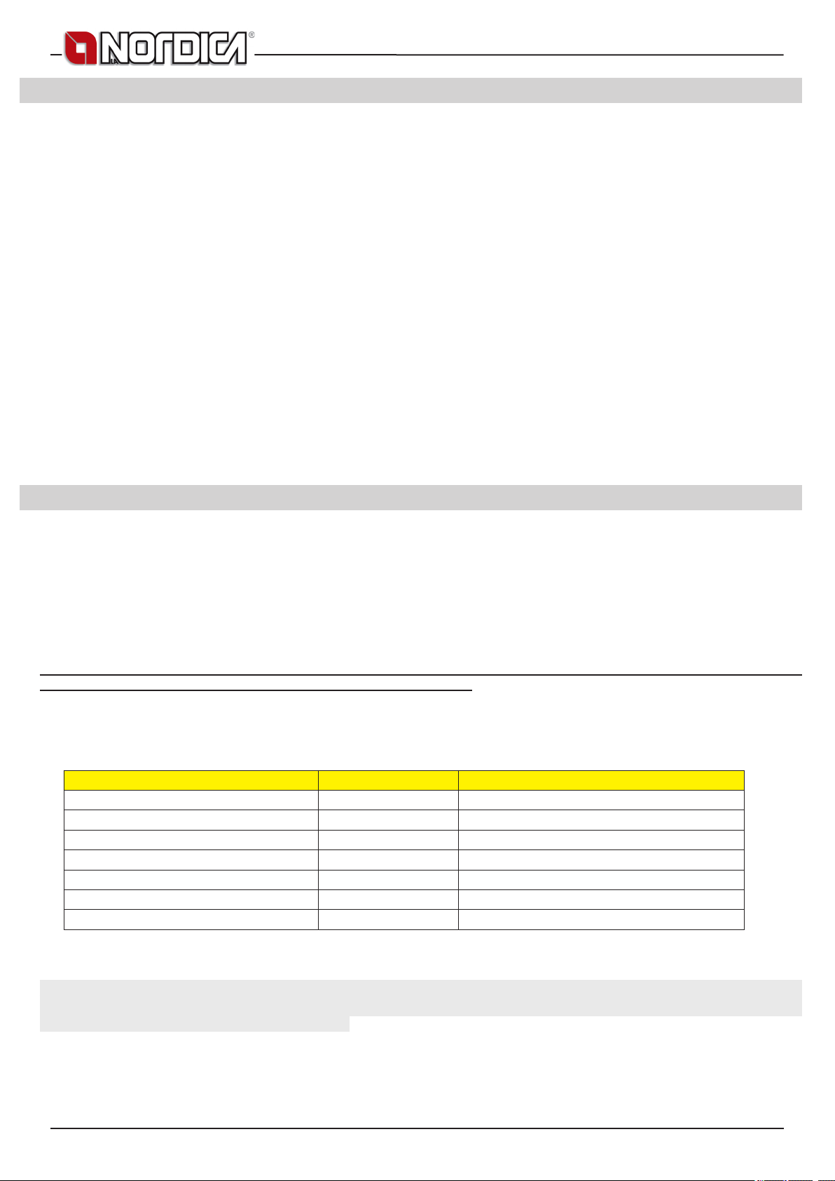
MONOBLOCCO 800 ANGOLO
8. CONNECTION AND MAINTENANCE OF VENTILATION (OPTIONAL)
The control unit and the plant must be installed and connected by authorized personnel according to the standards in force. (see
chapter GENERAL REMARKS).
ATTENTION: the control unit and the feeding cable must not be in contact with hot parts.
On our products, it is possible to install Optional ventilation kits suitable to improve the distribution of heat by ventilation only either of the
installation room or of the adjacent local (see chapter EXTERNAL AIR INTAKE).
For the installation of the Forced Ventilation Kit, follow the given instructions. (see chapter VENTILATION HOOD OR ADJACENT LOCAL).
The Kit is made up of a centrifugal fan, a lighting and adjustment control unit, and a (TM) thermostat that lets the fan start when the device
is properly heated and lets it stop when the fan is partially cold.
The lighting and the adjustment is carried out through the proper standard supplied control unit that has to be installed far from any direct
heat source.
CONNECTION (see chapter OPTIONAL VENTILATION KIT):
Connect the feeding cable of the switchboard with an electronic bipolar switch respecting at least a 3 mm distance between the contacts
(power supply 230V~ 50 Hz, it is necessary to provide for the correct connection to the grounding plant).
WARNING: The COMMAND must be connected to the mains with a differential line cut-off switch according to the regulations in force.
Correct operation of the command is assured only for the proper motor for which it has been manufactured. Improper use relieves the
manufacturer from each responsibility.
9. ALLOWED / NOT ALLOWED FUELS
Allowed fuels are logs. Use exclusively dry logs (max. content of water 20%). Maximum 3 logs should be loaded. The pieces of wood
should have a length of ca. 20-30 cm and a maximum circumference of 30-35 cm.
Compressed not worked-out wood briquettes must be used carefully to avoid overheating that may damage the device, since
these have a very high caloric value.
The wood used as fuel must have a humidity content lower than the 20% and must be stored in a dry place. Humid wood tends to burn
less easily, since it is necessary a greater quantity of energy to let the existing water evaporate. Moreover, humid content involves
the disadvantage that, when temperature decreases, the water condensates earlier in the hearth and therefore in the stack causing a
remarkable deposit of soot with following possible risk of re of the same.
Fresh wood contains about 60% of H2O, therefore it is not suitable to be burnt.
It is necessary to place this wood in a dry and ventilated place (for example under a roong) for at least two years before using it.
Besides others, it is not possible to burn: carbon, cuttings, waste of bark and panels, humid wood or wood treated with paints,
plastic materials; in this case, the warranty on the device becomes void.
Paper and cardboard must be used only to light the re.
The combustion of waste is FORBIDDEN and would even damage the appliance and the ue, causing health damages and claims by
the neighborhood owing to the bad smell.
The wood is not a fuel which allows a continuous operation of the appliance, as consequence the heating all over the night is not possible.
Variety kg/mc kWh/kg moistness 20%
Beech
Oak
Elm
Poplar
Larch*
Spruce*
Scots pine *
750 4,0
900 4,2
640 4,1
470 4,1
660 4,4
450 4,5
550 4,4
* RESINOUS WOOD NOT SUITABLE FOR THE BURNING
ATTENTION : the continuous and protracted use of aromatic wood (eucalyptus, myrtle etc.) quickly damages the cast iron parts
(cleavage) of the product.
The declared technical data have been achieved by burning beech wood class “A1” according to the requirement UNI EN ISO 17225-5
and wood moisture content less than 20%. By burning a different kind of wood the efciency of the product itself could change and some
specic adjustments on the appliance could be needed.
20 6098401
Page 21

MONOBLOCCO 800 ANGOLO
10. LIGHTING
After the rst ignition you can smell bad odours (owing to the drying of the glue used in the garnitures or of the paint) which disappear after
a brief using of the appliance. A good ventilation of the room should always be guaranteed.
T light the re, it is suggested to use small wood pieces together with paper or other traded lighting means.
It is FORBIDDEN to use any liquid substance as for ex. alcohol, gasoline, oil and similar.
Open the primary air completely.
When wood starts to burn, it is possible to feed it again by opening slowly the door, in order to avoid leaks of smoke, and close the
primary air register and control the combustion through the secondary air register according to the provisions of chapter TECHNICAL
DESCRIPTION. Please always be present during this phase.
Never overload the appliance (see the technical table - max. quantity of fuel that can be loaded / hourly consumption).
Too much fuel and too much air for combustion can cause overheating and therefore damage the same.
Never switch on the device when there are combustible gases in the room.
To perform a correct rst lighting of the products treated with paints for high temperature, it is necessary to know the following information:
• the construction materials of the involved products are not homogeneous, in fact there are simultaneously parts in cast iron, steel,
refractory material and majolica;
• the temperature to which the body of the product is subject is not homogeneous: from area to area, variable temperatures within
the range of 300°C - 500°C are detected;
• during its life, the product is subject to alternated lighting and extinguishing cycles in the same day, as well as to cycles of intense
use or of absolute standstill when season changes;
• the new appliance, before being considered seasoned has to be subject to many start cycles to allow all materials and paints to
complete the various elastic stresses;
• in detail, initially it is possible to remark the emission of smells typical of metals subject to great thermal stress, as well as of wet
paint. This paint, although during the manufacture it is backed at 250 °C for some hours, must exceed many times and for a given
period of time the temperature of 350 °C before becoming completely embedded in the metallic surfaces.
Therefore, it is extremely relevant to take these easy steps during the lighting:
1. Make sure that a strong air change is assured in the room where the appliance is installed.
2. During the rst starts, do not load excessively the combustion chamber (about half the quantity indicated in the instructions manual)
and keep the product continuously ON for at least 6-10 hours with the registers less open than the value indicated in the instructions
manual.
3. Repeat this operation for at least 4-5 or more times, according to your possibilities.
4. Then load more and more fuel (following in any case the provisions contained in the installation booklet concerning maximum load)
and, if possible, keep the lighting periods long avoiding, at least in this initial phase, short ON/OFF cycles.
5. During the rst starts, no object should be leaned on the appliance and in detail on enamelled surfaces. Enamelled surfaces must
not be touched during heating.
6. Once the «break-in» has been completed, it is possible to use the product as the motor of a car, avoiding abrupt heating with
excessive loads.
After testing the proper working of the appliance, some days from the installation, it is possible to proceed with the construction
of its aesthetic covering.
WARNING: During the surround building operations it must kept in mind possible and subsequent electrical installed parts maintenance
(Fans, temperature probe, etc) and with hydraulic systems all parts connected to the thermo-replace.
10.1. LOW EMISSION re lighting
Smokeless combustion is a way of lighting a re able to signicantly reduce the emission of harmful substances. The wood burns gradually
from the top downwards, so combustion is slower and more controlled. Burnt gases pass through the high temperatures of the ame and
therefore burn almost completely.
Place the logs in the hearth a certain distance apart as shown in the Picture 16 at page 65. Arrange the largest at the bottom and the
smallest at the top, or vertically in the case of tall narrow combustion chambers. Place the re starter module on top of the pile, arranging
the rst logs in the module at right angles to the pile of wood.
Fire STARTER MODULE
This re starter module replaces a paper or cardboard starter.
Prepare four logs, 20 cm long with a cross section of 3 cm by 3 cm Picture 16 at page 65. Cross the four logs and place them on top of the
pile of wood at right angles, with the re lighter (wax impregnated wood bre for example) in the middle. The re can be lit with a match.
If you want, you can use thinner pieces of wood. In this case, you will need a larger quantity.
Keep the ue gas exhaust valve and combustion air regulator open (1A - 2A). After lighting the re, leave the combustion air regulator
open in the position shown in the Picture 16 at page 65.
IMPORTANT:
• do not add further wood between one complete load and the next;
• do not suffocate the re by closing the air intakes;
• regular cleaning by a chimney sweep reduces ne particle emissions.
These instructions are backed by ENERGIA Legno SVIZZERA www.energia-legno.ch
6098401 21
Page 22

MONOBLOCCO 800 ANGOLO
11. NORMAL OPERATION
After having positioned the registers correctly, insert the indicated hourly wood load avoiding overloads that cause anomalous stresses
and deformations. You should always use the product with the door closed in order to avoid damages due to overheating (forge
effect). The inobservance of this rule makes the warranty expire.
With the registers located on the front of the device, it is possible to adjust the heat emission of the same. They have to be opened
according to the caloric need. The best combustion (with minimum emissions) is reached when, by loading the wood, most part of the air
for combustion ows through the secondary air register.
Never overload the appliance. Too much fuel and too much air for the combustion may cause overheating and then damage the
product.
You should always use the appliance with the door closed in order to avoid damages due to overheating (forge effect).
The adjustment of the registers necessary to reach the rated caloric yield with a depression at the stack of 12 Pa (=1.2 mm of column
of water) is the following one: see chap. TECHNICAL DESCRIPTION. The appliance works as an intermittent operating appliance.
Besides the adjustment of the air for the combustion, the intensity of the combustion and consequently the thermal performance of the
device is inuenced by the stack. A good draught of the stack requires a stricter adjustment of air for combustion, while a poor draught
requires a more precise adjustment of air for combustion.
To verify the good combustion, check whether the smoke coming out from the stack is transparent.
If it is white, it means that the device is not properly adjusted or the wood is too wet; if instead the smoke is gray or black, it signals that the
combustion is not complete (it is necessary a greater quantity of secondary air).
WARNING: When fuel is added onto the embers in the absence of a ame, a considerable amount of fumes may develop. Should this
happen, an explosive mixture of gas and air may form, and in extreme cases an explosion may occur. For safety reasons it is advisable
to perform a new lighting procedure with the use of small strips.
11.1. OPERATION DURING TRANSITION PERIODS
During transition periods when the external temperatures are higher, if there is a sudden increase of temperature it can happen that the
combustion gases inside the ue cannot be completely sucked up.
The exhaust gases do not come out completely (intense smell of gas). In this case, shake the grating more frequently and increase the air
for the combustion. Then, load a reduced quantity of fuel in order to permit a rapid burning (growing up of the ames) and the stabilization
of the draught.
Then, check that all openings for the cleaning and the connections to the stack are air-tight. In case of doubt, do not operate the product.
12. SUMMER STOP
After cleaning the hearth, chimney and hood, totally eliminating the ash and other eventual residues, close all the doors of the hearth
and the relevant registers; in case you disconnect the appliance from the chimney you must close its openings in order to let work others
possible appliances connected to the same ue.
We suggest performing the cleaning operation of the ue at least once per year; verifying in the meantime the actual status of the rope
seals, which cannot ensure the good operation of the equipment if they are not in good condition and are not making a good seal! In this
case the seals must be replaced.
In presence of dampness in the room where the stove has been placed, we advise you to put absorbent salts into the hearth.
If you want to keep for long the aesthetic look of the cooker it is important to protect its internal walls in row cast iron with neutral Vaseline.
13. MAINTENANCE AND CARE
Check the external air intake, by cleaning it, at least once a year. The stack must be regularly swept by the chimney sweeper.
Let your chimney sweeper in charge of your area check the regular installation of the device, the connection to the stack and the aeration.
IMPORTANT: The maintenance must be carried out only and exclusively with cold device .You should only use spare parts approved
and supplied by La NORDICA S.p.A. . Please contact your specialized retailer if you require spare parts. YOU MUST NOT MAKE
ANY CHANGES TO THE DEVICE!!!
13.1. GLASS CLEANING
After having checked that the door is completely shut (lowered), unlock the upper latch (Picture 9 at page 63 pos. A), open the ap and
clean the glass, then close the ap and lock the latch before lifting again the door.
Thanks to a specic inlet of secondary air, the accumulation of dirty sediments on the glass-door is reduced with efcacy. Nevertheless this
can never be avoided by using solid fuels ( particularly wet wood ) and it has not to be understood as a defect of the appliance.
IMPORTANT: The cleaning of the sight glass must be carried out only and exclusively with cold device to avoid the explosion of
the same. For the cleaning, it is possible to use specic products or a wet newspaper paper ball passed in the ash to rub it. Do not
use cloths, abrasive or chemically aggressive products by cleaning the hearth glass.
The correct lighting phase, the use of proper quantities and types of fuels, the correct position of the secondary air regulator, enough
draught of the chimney-ue and the presence of combustion air are the essential elements for the optimal functioning of the appliance and
for the cleaning of the glass.
BREAK OF GLASSES: Given that the glass-ceramic glasses resist up to a heat shock of 750°C, they are not subject to thermal
shocks. Their break can be caused only by mechanic shocks (bumps or violent closure of the door, etc.). Therefore, their
replacement is not included in the warranty.
22 6098401
Page 23
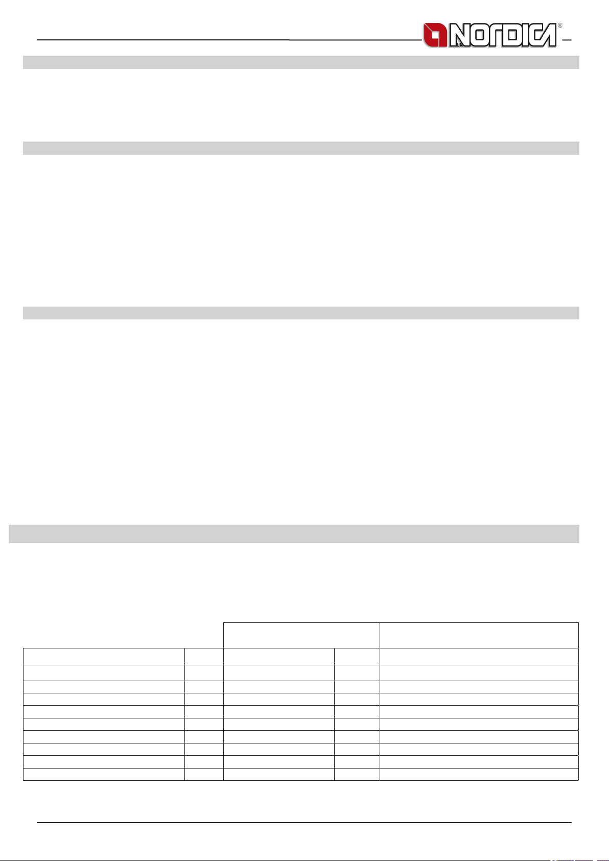
MONOBLOCCO 800 ANGOLO
13.2. CLEANING OUT THE ASHES
All the devices are equipped with a hearth grating and an ash drawer for the collection of the ashes.
It is suggested to empty periodically the ash drawer and to avoid it lls completely in order not to overheat the grating. Moreover, it is
suggested to leave always 3-4 cm of ash in the hearth.
CAUTION: The ashes removed from the hearth have to be stored in a container made of re-resistant material equipped with an
air-tight cover. The container has to be placed on a re-resistant oor, far from ammable materials up to the switching off
and complete cooling.
13.3. CLEANING THE FLUE
The correct lighting phase, the use of proper quantities and types of fuels, the correct position of the secondary air regulator, enough
draught of the chimney-ue and the presence of combustion air are the essential elements for the optimal functioning of the appliance.
The device should be completely cleaned at least once a year or every time it is a needed (in case of bad working and low yield). An
excessive deposit of soot can cause problems in the discharge of smokes and re in the ue.
The cleaning must be carried out exclusively with cold equipment. This operation should be carried out by a chimney sweeper who
can simultaneously perform an audit of the ue (checking of possible deposits).
During the cleaning, it is necessary to remove the ash drawer, the grating, and the smoke deectors from the device in order to ease the
fall of the soot. The deectors can be easily extracted from their seats since they are not fastened using screws. Once the clearing has
been carried out, place them back in their seats (Picture 10 at page 63).
CAUTION: The lack of the deectors causes a strong depression, with a too fast combustion, an excessive consumption of wood
with related overheating of the device.
13.4. MAINTENANCE OF THE EXTENSIBLE GUIDES
To work silently, as well as in a reliable and robust way, the doors are fastened to the extensible ball guides. By using the device continuously,
the lubricant of the guides tends to run out progressively in time making their sliding more difcult and noisy. For this reason, together
with each device a high temperature grease is supplied in order to make the lubrication of the guides possible for the user, in case it
becomes necessary (excessive noise or reduction of smoothness). After having completely lifted the door of the stack, using a syringe,
apply internally on the track on a visible point, as high as possible, two grease balls (corresponding to 0.5 ml of the graduated scale of the
syringe). Pay attention not to exceed the suggested quantity. Repeat the same operation on the other track and lift and lower the door many
times so that the grease distributes on all balls. CAUTION: use exclusively the grease supplied by La NORDICA.
14. CALCULATION OF THE THERMAL POWER
There is not an absolute rule for calculating the correct necessary power. This power is given according to the space to be heated, but it
depends also largely on the insulation. On an average, the caloric value necessary for a properly insulated room is 30 kcal/h per m3 (for
an external temperature of 0°C).
Given that 1 kW corresponds to 860 kcal/h, it is possible to adopt a value of 38 W/m3.
Let’s suppose one wishes to heat a room of 150 m3 (10 x 6 x 2.5 m) in an insulated apartment. In this case, it is necessary to have 150 m3
x 38 W/m3 = 5700 W or 5,7 kW. As main heating, a 8 kW device is therefore sufcient.
Approximate combustion value Required quantity in relation to 1 kg of dry
wood
Fuel Unit kcal/h kW
Dry wood (15% humidity) kg 3600 4.2 1,00
Wet wood (50% humidity) kg 1850 2.2 1,95
Wood briquettes kg 4000 5.0 0,84
Brown coal briquettes kg 4800 5.6 0,75
Normal anthracite kg 7700 8.9 0,47
Coke kg 6780 7.9 0,53
Natural gas m
Naphtha L 8500 9.9 0,42
Electricity kW/h 860 1.0 4,19
3
7800 9.1 0,46
6098401 23
Page 24

MONOBLOCCO 800 ANGOLO
15. GUARANTEE TERMS
GUARANTEE TERMS
1. La Nordica S.p.A. products are guaranteed, within the European community, for 24 months from the date of purchase.
Purchase has to be proved by means of a valid scal document issued by the seller (receipt, invoice or shipment document) identifying the
purchased product and its purchase and/or delivery date.
WARNING: This conventional guarantee does not replace the guarantee regulated by the European legislation on consumer
rights.
The conventional guarantee is only applicable to the Italian region and to those areas, within the European Community, where the
Authorised Technical Assistance Centres are active (see the www.lanordica-extraame.com website)
It is also limited to the state of residence of the consumer, which must coincide with the premises and/or registered ofce of the seller of
the La Nordica S.p.A. product
These regulations do not apply if the product is purchased within commercial, entrepreneurial, or professional circumstances. In these
cases the product guarantee will be limited to a period of 12 months from the date of purchase.
ITALIAN GUARANTEE
What must be done if there is a product malfunction:
Consult the instructions manual to make sure the malfunction cannot be solved by using the product correctly. Make sure the malfunction
is included in those covered by the guarantee; otherwise the cost of the intervention will be borne entirely by the consumer. When
requesting the intervention of the Assistance service at the Authorised Assistance Centre, always specify: - type of malfunction - model of
the appliance - complete address - phone number
EUROPEAN GUARANTEE
What must be done if there is a product malfunction:
Consult the instructions manual to make sure the malfunction cannot be solved by using the product correctly. Make sure the malfunction
is included in those covered by the guarantee; otherwise the cost of the intervention will be borne entirely by the consumer. Request the
intervention of the Assistance service or the address of the Authorised Technical Assistance Centre to the seller; always specify: type of
malfunction, model of the appliance, complete address and phone number
If the malfunction arises in the rst 6 months of the product’s life, the consumer has the right to have the product repaired with
no expense.
From the seventh to the twenty-fourth month, if a malfunction arises, the consumer will bear the cost of the call, while the seller
will pay for the manpower and for any spare parts used.
2. If the malfunction is linked to external events and/or conditions such as, including but not limited to, insufcient capacity of the systems;
wrong installation and/or maintenance by the personnel which hasn’t got the skills prescribed by the laws of the country of residence of
the consumer; negligence; inability to use the product and wrong maintenance by the consumer, with respect to what is reported and
recommended by the instructions manual of the product, which is part of the sales contract, this guarantee will be void.
Damage to the product that cannot be related to manufacturing defects are also not included in this guarantee. Similarly are excluded
defects related to incorrect operation of the ue, according to the legislation in force in the country at the moment of purchase. Other
exclusions include all product defects due to carelessness, accidental breakdown, tampering and/or damage during transport (scratches,
dents, etc.), interventions carried out by unauthorised personnel and further damage caused by incorrect interventions by the consumer
trying to arrange the initial malfunction.
The following consumables are excluded by the guarantee: gaskets, ceramic or tempered glasses, cast iron grilles or coatings, refractory
materials (e.g. Nordiker or others), painted, chrome-plated or golden parts, majolica ware, handles, the brazier and its related components.
For Idro products the heat exchanger is not covered by the guarantee if a suitable condensation-proof circuit is not set up to ensure a
return temperature of the device of at least 55°C. The guarantee excludes all the external components on which the consumer can directly
operate during use and/or maintenance or that can be subject to wear and/or rust and stains on steel due to aggressive detergents.
If malfunctions are signalled which are not later conrmed during check by an authorised technician, the cost of the intervention will be
borne entirely by the consumer.
3. If it is not possible to restore product conformity by repairing it, the product/component will be replaced, the guarantee expiration date
and conditions will remain the same established when the product/component to be replaced has been purchased.
4. La Nordica S.p.A. cannot be held liable for injury or damage which may - either directly or indirectly - be caused to persons, animals
and property ensuing from failure to observe all the instructions provided in the relevant instruction manual and the warnings regarding
installation, use and maintenance of the product, that can also be downloaded on the website.
5. Interventions for adjusting and/or regulating the product for the type of fuel or other reasons are excluded by the guarantee.
6. If the product is repaired in one of the Authorised Technical Assistance Centres indicated by La Nordica S.p.A. and if the product is
replaced, transport will be free of charge. If the technician can repair the product at the user’s place of residence and they refuse, transport
to the workshop and redelivery will be paid by the consumer.
24 6098401
Page 25

MONOBLOCCO 800 ANGOLO
7. After the 24 months of the guarantee have elapsed any repair intervention cost will be completely borne by the consumer.
8. In the case of disputes the only competent court is that of the La Nordica S.p.A. registered ofce - (Vicenza-Italy)
ADDITIONAL WARNINGS
• Only use the fuel recommended by the manufacturer. The product must not be used as an incinerator.
• Do not use the product as a ladder or supporting structure.
• Do not place laundry on the product to dry it. Any clothes-horse or similar objects must be kept at due distance from the product.
Danger of re or damage to the coating.
• The user is fully liable for any incorrect use of the product. The manufacturer bears no civil or criminal liability for incorrect use.
• Unauthorised tampering of any nature or replacement of spare parts of the product with non-original parts may endanger the
operator and the manufacturer bears no civil or criminal liability for this.
• Large parts of the surface of the product can get very hot (door, handle, glass, smoke outlet pipes, etc.). Please therefore avoid
coming into contact with these parts without wearing suitable protective clothing or using appropriate measures, such as heat
protective gloves.
• DO NOT use the product with the door open or if the glass is broken.
• The product must be electrically connected to a system equipped with an operational earthing system.
• Turn off the product in the event of a failure or malfunctioning.
• Do not wash the product with water. Water may penetrate into the unit and cause faults in the electrical insulation. This can cause
electric shocks.
• Installations not complying with the regulations in force, as well as incorrect use and failure to comply with the maintenance
scheduled by the manufacturer, will invalidate the guarantee.
6098401 25
Page 26

MONOBLOCCO 800 ANGOLO
DasaufdemProduktoderderVerpackungangebrachteSymbolbesagt,dassdasProduktnichtalsnormalerHausmull
anzusehen ist, sondern bei speziellen Sammelstellen für das Recycling von Elelktro- und Elektronik-Altgeraten
abzugebenist.DurchdieordnungsgemäßeEntsorgungdiesesProdukteswerdenmöglichenegativeFolgenvermieden,
die aus einer unsachgemäßen Entsorgung. des Produktes entstehen konnten. Ausführlichere Informationen zum
Recycling,diesesProdukteslieferndasGemeindeamt,derörtlicheMüllentsorgungsdienstoderderHändler,beidem
dasProduktgekauftwurde
KONFORMITÄTSERKLÄRUNG DES HERSTELLERS
Betreff:Fehlen von Asbest und Kadmium
Wirbestätigen,dassdieverwendetenMaterialenoderTeilenfürdieHerstellungderLaNordicaGeräteohneAsbestund
DerivatsindundauchdasLotfürdasSchweißenimmerohneKadmiumist.
Betreff:Ordnung CE n. 1935/2004.
WirerkläreninalleinigerVerantwortung,dassdieMaterialenderTeile,diefürdenKontaktmitLebensmittelnvorgesehen
sind,fürdieNahrungsbenutzunggeeignetsindundderRichtlinienCEn.1935/2004erfüllen.
DEUTSCH - INHALTSVERZEICHNIS
1. INSTALLATION ...............................................................................................................................................................................3
2. ALLGEMEINE HINWEISE ............................................................................................................................................................ 27
3. INSTALLATIONSVORSCHRIFTEN .............................................................................................................................................. 27
4. BRANDSCHUTZ ............................................................................................................................................................................27
4.1. NOTHILFEINTERVENTION..........................................................................................................................................................................28
4.2. TRÄGERSCHUTZ
5. BESCHREIBUNG ..........................................................................................................................................................................28
6. SCHORNSTEINROHR ..................................................................................................................................................................29
6.1. SCHORNSTEIN............................................................................................................................................................................................29
6.2. VERBINDUNGZUMSCHORNSTEINROHR................................................................................................................................................29
6.3. LUFTFÜRDIEVERBRENNUNG.................................................................................................................................................................29
6.4. LUFTEINLASS
7. LÜFTUNG HAUBE ODER ANLIEGENDEN RAUM ......................................................................................................................30
8. LÜFTUNGSVERBINDUNG UND – WARTUNG (OPTIONAL) ......................................................................................................31
9. ZULÄSSIGE / UNZULÄSSIGE BRENNSTOFFE .......................................................................................................................... 31
10. ANFEUERUNG ..............................................................................................................................................................................32
10.1. EMISSIONSARMESAnfeuern......................................................................................................................................................................32
11. NORMALER BETRIEB .................................................................................................................................................................. 33
11.1. BETRIEBINDENÜBERGANGSPERIODEN...............................................................................................................................................33
12. SOMMERPAUSE ........................................................................................................................................................................... 33
13. WARTUNG UND PFLEGE ............................................................................................................................................................33
13.1. REINIGUNGDESGLASES..........................................................................................................................................................................33
13.2. REINIGUNGDESASCHENKASTENS.........................................................................................................................................................34
13.3. REINIGUNGDESSCHORNSTEINROHRES...............................................................................................................................................34
13.4. WARTUNGDERTELESKOPFÜHRUNGEN................................................................................................................................................34
14. FESTSTELLUNG DER WÄRMELEISTUNG .................................................................................................................................34
15. GARANTIEBEDINGUNGEN .........................................................................................................................................................35
16. EXTRA KIT GEBLÄSE ..................................................................................................................................................................66
17. TECHNISCHE PROTOKOLLE ......................................................................................................................................................68
18. MAßE .............................................................................................................................................................................................70
.........................................................................................................................................................................................28
..............................................................................................................................................................................................30
26 6098401
Page 27

MONOBLOCCO 800 ANGOLO
2. ALLGEMEINE HINWEISE
La NORDICA S.p.A. Verantwortung ist auf die Lieferung des Gerätes begrenzt.
Ihre Anlage muss den anerkannten Regeln der Technik entsprechend verwirklicht werden, auf der Grundlage Vorschriften der vorliegenden
Anleitungen und den Regeln des Handwerks, von qualiziertem Personal, dass das im Namen von Firmen handelt, die in der Lage sind,
die volle Verantwortung für die Anlage zu übernehmen.
La NORDICA S.p.A. ist nicht für ein Produkt verantwortlich, an dem nicht genehmigte Veränderungen vorgenommen wurden und
ebenso wenig für den Gebrauch von Nicht-Original Ersatzteilen.
Dieses Gerät ist nicht für den Gebrauch von unerfahrenen Personen(einschließlich Kindern) mit physischen, sensorischen und geistigen
Fähigkeiten geeignet, außer wenn sie über den Gebrauch des Gerätes von einer für Ihre Sicherheit verantwortlichen Person kontrolliert
und unterrichtet werden sein. Man darf die Kindern kontrollieren, um sicher zu sein, dass sie nicht mit dem Gerät spielen werden.(EN
60335-2-102/7.12).
Nationale und europäische, örtliche und baurechtliche Vorschriften sowie feuerpolizeiliche Bestimmungen sind einzuhalten.
DAS GERÄT DARF NICHT ABGEÄNDERT WERDEN! Sollten diese Vorkehrungen nicht eingehalten werden, übernimmt die
Gesellschaft La NORDICA S.p.A. keinerlei Haftung.
3. INSTALLATIONSVORSCHRIFTEN
Die Installation des Produckt und der zur Heizungsherde gehörigen Zusatzausstattung muss sämtlichen geltenden und vom Gesetz
vorgesehenen Normen und Vorschriften entsprechen.
Die Installation, die entsprechenden Anschlüsse der Anlage, die Inbetriebnahme und die Überprüfung der korrekten Funktion müssen
von entsprechend geschultem, autorisierten Fachpersonal fachgerecht und unter Einhaltung der national, regional und lokal geltenden
Bestimmungen des Landes ausgeführt werden, in welchem das Gerät zum Einsatz kommt. Ferner sind diese Anleitungen einzuhalten.
Die Installation muss von einem autorisierten Fachmann ausgeführt werden, der dem Käufer eine Konformitätsbescheinigung der Anlage
ausstellen muss und die komplette Verantwortung für die denitive Installation und die daraus folgende reibungslose Funktion des
installierten Produktes übernimmt.
Vor der Installation folgende Prüfungen ausführen:
• Prüfen, dass der Boden das Gewicht des Gerätes tragen kann und für eine zweckmäßige Isolierung sorgen, wenn es sich um
einen Boden aus brennbarem Material handelt (AUSMASSE GEMÄSS DER REGIONALEN VERORDNUNGEN).
• Sicherstellen, dass es in dem Raum in dem dieser installiert wird, eine geeignete Lüftung vorhanden ist
• Die Installation in Räumen mit Sammellüftungsrohrleitungen, Hauben mit oder ohne Abzieher, Gasgeräten des Typ B, Wärmepumpen
oder bei Vorhandensein von Geräten, deren gleichzeitiger Betrieb den Raum zum Unterdruck (Norm UNI 10683 bringen kann, ist
zu vermeiden.
• Sicherstellen, dass das Schornsteinrohr und die Rohre, die mit dem Gerät verbunden werden, für den Betrieb mit dem Gerät
geeignet sind. Der Anschluss mehrerer Öfen an denselben Schornstein ist zulässig.
• Der Durchmesser der Öffnung für den Schornsteinanschluss muss mindestens dem Durchmesser des Rauchrohrs entsprechen.
Die Öffnung sollte mit einem Wandanschluss zum Einsetzen des Abzugsrohrs und einer Scheibe ausgestattet sein.
• Immer für jede Modell den vorgeschriebenen freien Raum zwischen den Thermokamin und die Wände lassen, (Siehe seite
AUSZEICHNUNGSINFORMATIONEN).
• Das Lüftungssystem entscheiden (natürlich oder erzwungen) Siehe LÜFTUNG HAUBE ODER ANLIEGENDEN RAUM.
• Dank der einstellbaren Füsse und dem Gebrauch einer Libelle sich versichern, dass die Ausrüstung vollkommen gerade ist, um die
korrekte Abgleitung der Tür zu ermöglichen.
Bitte erst nach einigen
WARNUNG: Bei der Konstruktion der Auskleidung, muss man eventuelle spätere Wartung der installierten elektrischen Komponenten
(z.B. Gebläse, Temperaturfühler,) und bei einem Hydraulischesystem, Vorrichtungen der Wasserführenden Geräte bedenken.
La NORDICA S.p.A. haftet nicht für Produkte, die ohne Genehmigung geändert wurden, und ebenso wenig, wenn keine
Originalersatzteile verwendet wurden.
Ihr gewohnter Bezirksschornsteinfeger ist von der Installation des Heizungsherds zu unterrichten, damit er seinen ordnungsgemäßen
Anschluss an den Rauchabzug und dessen Leistungsvermögen überprüfen kann.
Tagen mit dem Verkleidungseinbau weitergehen, wenn man sicher ist, dass das Gerät korrekt funktioniert.
4. BRANDSCHUTZ
Bei der Aufstellung der Ausrüstung müssen folgende Sicherheitsvorrichtungen beachtet werden:
a) Um eine ausreichende Wärmedämmung zu gewährleisten, muss die Mindestanforderungen für Sicherheitsabstand (siehe
AUSZEICHNUNGSINFORMATIONEN - Abbildung 7 at page 62) eingehalten werden. Alle Sicherheitsabstände sind auf der
Typenschild des Produktes gezeigt und dürfen nicht unter der angegebenen Werte liegen.
b) Vor der Tür des Feuerraumes sowie in ihrem Ausstrahlungsbereich dürfen sich in einer Entfernung von mindestens 80 cm kein
entammbarer oder hitzeempndlicher Gegenstand oder Baumaterial benden. Diese Entfernung kann auf 40 cm verringert werden,
wenn vor dem gesamten zu schützenden Bauteil eine beidseitig belüftete und hitzebeständige Schutzvorrichtung angebracht wird.
c) Wenn das Produkt auf einem leicht entzündlichen Boden installiert wird, muss ein feuerfester Unterbau vorgesehen werden.
Fußböden aus brennbaren Materialien wie Teppich, Parkett oder Kork, etc., müssen durch einen entsprechenden Belag aus
nicht brennbaren Baustoffen, zum Beispiel Keramik Stein, Glas oder Stahl, etc. geschützt werden (Abmessungen nach der
regionalen Ordnung) siehe Abbildung 1 auf Seite 59.
Der Produkt darf ausschließlich mit eingefügtem Aschenkasten in Betrieb genommen werden.
Die festen Verbrennungsreste (Asche) sind in einem dichten und feuerfesten Behälter zu sammeln. Das Produkt darf nicht eingeschaltet
6098401 27
Page 28

MONOBLOCCO 800 ANGOLO
werden, bei Vorhandensein von Gas- oder Dampfemissionen (zum Beispiel Linoleumkleber, Benzin, usw. ) Keine brennbaren Materialien
in die Nähe des Gerätes stellen.
Während der Verbrennung wird thermische Energie freigesetzt, die eine deutliche Erwärmung der Oberächen, der Türe, des Glases des
Feuerraums, der Griffe der Türen oder der Steuerungen, des Rauchabzugrohrs und eventueller Vorderteile des Produkts, zu Folge hat.
Den Kontakt mit diesen Elementen vermeiden, wenn man keine Schutzkleidung trägt oder über entsprechendes Zubehör verfügt
(Wärmeschutzhandschuhe, Steuervorrichtungen).
Benutzt man falsche oder feuchte Brennmittel, kann es zu Ablagerungen im Rauchabzug kommen (Kreosot) und es besteht die
Gefahr, dass der Rauchabzug Feuer fängt.
Wiesen Sie Kinder darauf hin, dass das Produkt sehr heiß wird und nicht berührt werden darf. Kinder müssen die Gefahren
dieses Gerätes kennen und während des Betriebs auf Abstand gehalten werden.
Wenn falscher oder zu feuchter Brennstoff verwendet wird, könnte aufgrund von Ablagerungen im Rauchabzug ein Kaminbrand entstehen.
4.1. NOTHILFEINTERVENTION
Sollte Brand im Schornstein oder im Schornsteinrohr auftreten:
a) Unverzüglich die Verbrennungslufteingänge schließen.
b) Die Einstellvorrichtungen für sauerstofftragende Luft schließen
c) Das Feuer durch die Anwendung von Kohlendioxidlöschern (CO2 Pulverlöscher) erlöschen
d) Den unverzüglichen Eingriff der FEUERWEHRMÄNNER erfordern
NIE DAS FEUER DURCH WASSERSTRAHLEN ERLÖSCHEN. Sobald der Schornstein aufgehört hat zu brennen, Prüfung durch einen
Spezialisten durchführen lassen, um allfällige Risse oder durchlässige Stellen aufnden zu können.
4.2. TRÄGERSCHUTZ
Mit Rücksicht auf die Abstrahlung der Feuerstelle, ist es beim Entwurf Ihres Schornsteines besonders auf den Trägerschutz zu achten.
Auf einer Seite ist die Nähe des Trägers zu den Außenseiten der Feuerstelle, und auf der anderen die Abstrahlung der Glastür wichtig,
die normalerweise sehr nahe an den Trägern selbst ist. Man soll sich daran erinnern, dass die inneren oder unteren Oberächen dieses
Trägers aus brennbarem Material in keinem Fall in Berührung mit Temperaturen über 65°C treten müssen. Abbildung 2 auf Seite 59 gibt
einige Lösungsbeispiele an.
WARNUNG: Wir werden nicht für eine nicht mit den Vorschriften dieser Anweisungen übereinstimmende Anlage oder im Falle
von Anwendung von nicht gebrauchsgeeigneten Ergänzungsprodukten haften.
5. BESCHREIBUNG
Denition: Gerät gemäß EN 13229, Zeitbrandfeuerstätte.
Die Ausrüstung besteht aus Platten in lackierten Stahlbleche, Gussteile in Gusseisen und aus feuerfesten Materialen.
Die Feuerstelle ist mit Gusstücke in Gusseisen und feuerfesten Platten verkleidet, der Gitterträger und die dazugehörige ausziehbare Gitter
sind beide aus Gusseisen .Der Satz der Kammer ist dicht durch Schweissen und ist mit einer Deckung aus verzinktem Blech verkleidet.
Die Ausrüstungen Modell 800 sind mit einer Feuerstelle mit Doppeldickerückseite, bestehend aus einer gelochten ausziehbaren
Platte.
Durch diese Löcher kommt geheizte Luft in die Feuerkammer und man erreicht eine Nachverbrennung mit einer Steigerung der
Wirkungsgrad und einen Verminderung der unverbrannten Gase.
Die panoramische Tür ist auf Teleskopführungen eingesetzt ,die einen kräftigen ,leisen und in der Zeit zuverlässigen Betrieb versichern.
Die Gegengewichte zur Abhebung der Tür sind durch eine kräftige Kette mit dazugehörigem Ritzel gestützt.
Das Keramikglas , das bis auf 700°C beständig ist, gestattet eine faszinierende Sicht auf die brennenden Flammen. Außerdem, ist es auf
diese Weise möglich, jeden etwaigen Austritt von Funken und Rauch zu vermeiden.
Die Raumheizung erfolgt:
a) Durch Konvektion: Der Luftdurchgang durch den Mantel und der Einsatzverkleidungshaube trägt die Wärme in den Raum über.
b) Durch Strahlung: durch das Panoramaglas und den Gusseisenkörper ist die Wärme in den Raum gestrahlt.
Die Ausrüstung ist mit Einstellvorrichtungen für Primär- und Sekundärluft versehen, durch welche die Verbrennungsluft eingestellt werden
kann.
1A - Primärlufteinstellvorrichtung (Abbildung 8 auf Seite 63)
Dank der unter der Feuerstellentür gestellten Lufteinstellvorrichtung wird den Luftdurchgang zwischen dem Aschenkasten und dem
Gitter in Brennstoffrichtung eingestellt. Die Primärluft ist für den Verbrennungsvorgang notwendig.
• Das Modell 800 hat einen einzigen Schieber sowohl für die Primär- als für die Sekundärluft.
Der Aschenkasten muss regelmäßig entleert werden, so dass die Asche den Primärluftseintritt für die Verbrennung nicht behindern
kann. Durch die Primärluft ist es sogar möglich, das Feuer lebhaft brennend zu halten.
Während der Holzverbrennung, muss die Primärlufteinstellvorrichtung nur ein wenig geöffnet werden, da das Holz anderenfalls schnell
verbrennt und die Ausrüstung sich überheizen kann (Siehe Abschnitt NORMALER BETRIEB).
2A - Sekundärlufteinstellvorrichtung (Abbildung 8 auf Seite 63).
Die Sekundärluft strömt innen durch die beiden Seitenträger der Vorderfront, erwärmt sich, löst die doppelte Verbrennung aus und hält
dabei gleichzeitig das Glas rein (Schieber nach rechts).
Wenn der Hebel in der Mitte gestellt wird, das Monoblock 800 auf verminderten Betrieb läuft (Primärluft geschlossen, Sekundärluft auf
die Hälfte herabgesetzt (Siehe Abschnitt NORMALER BETRIEB).
Die Regelung der Einstellvorrichtungen, welche für die Erzielung der Nennwärmeleistung notwendig ist, ist die folgende:
BRENNSTOFF PRIMÄRLUFT SEKUNDÄRLUFT TERTIARY AIR
MONOBLOCCO 800 Holz OFFEN OFFEN Voraustarierte
28 6098401
Page 29

MONOBLOCCO 800 ANGOLO
ZUBEHÖR HOCHTEMPERATURFET
MONOBLOCCO 800 SCHON DABEI SCHON DABEI SCHON DABEI
SCHÜRHAKEN HANDSCHUH
6. SCHORNSTEINROHR
Grundsätzliche Anforderungen für den richtigen Betrieb der Ausrüstung:
• Das Innenteil soll vorzugsweise rund sein;
• Das Schornsteinrohr muss thermisch isoliert, wasserdicht, und mit Materialen aufgebaut sein, welche die Wärme, die
Verbrennungsprodukte und etwaige Kondensaten bestehen;
• Es muss keine Querschnittreduzierung aufweisen und muss einen senkrechten Lauf mit Biegungen nicht hoher al 45° haben;
• Wenn es schon angewandt worden ist, muss es sauber sein;
• Die technischen Angaben des Gebrauchshandbuches beachten;
Sollten die Schornsteinrohre einen viereckigen oder rechteckigen Querschnitt aufweisen, müssen die Innenkanten mit einem Radius nicht
kleiner als 20 mm abgerundet sein. Was den rechteckigen Querschnitt betrifft, muss das Verhältnis zwischen den Seiten = 1,5.
Ein zu kleiner Querschnitt verursacht eine Verminderung des Zuges. Eine Mindesthöhe von 4 m wird empfohlen.
Folgende Materialen sind verboten und gefährden demzufolge den richtigen Betrieb der Ausrüstung: Asbestfaserstoff, verzinkter Stahl,
innerliche rohe und porige Oberächen. Abbildung 3 auf Seite 59 gibt einige Losungsbeispiele an.
Der Mindestquerschnitt muss 4dm2 (zum Beispiel 20x20cm) für die Ausrüstungen mit Rohrquerschnitt kleiner als 200mm sein,
oder 6,25 dm2 (Zum Beispiel 25x25cm) für die Ausrüstungen mit Rohrquerschnitt großer als 200mm betragen.
Der von Ihrem Schornsteinrohr erzeugte Zug muss ausreichend aber nicht übertrieben sein.
Ein Schornsteinrohr mit einem zu weiten Querschnitt kann ein Volumen aufweisen, das zu groß zu heizen ist und das demzufolge
Betriebsstörungen bei der Ausrüstung verursachen kann. Um das zu vermeiden, ist das Schornsteinrohr seine ganze Höhe lang in einem
anderen Rohr einzuführen. Ein zu kleiner Querschnitt verursacht eine Zugverminderung.
ACHTUNG: im Hinblick auf den Anschluss an den Schornstein und brennbare Materialien muss man die Bestimmungen der Regel
UNI10683 einhalten. Der Schornsteinrohr muss von entzündlichen und wärmeempndlichen Materialen durch eine passende Isolierung
oder ein Luftzwischenraum entfernt sein.
Es ist VERBOTEN, innerhalb des Schornsteinrohrs Anlagerohre oder Luftanleitungen durchgehen zu lassen Abbildung 4 auf Seite 60.
6.1. SCHORNSTEIN
Der Zug des Schornsteinrohres hängt von der Tauglichkeit des Schornsteines an. Wenn der Schornstein handwerklich gebaut ist, muss
der Ausgangsquerschnitt zwangsmäßig zwei Male größer als der Innenquerschnitt des Schornsteinrohrs sein. Da er den Firstträger
immer überschreiten muss, muss der Schornstein das Abblasen auch dann sichern, wenn es Wind gibt (Abbildung 5 auf Seite 60 -
Abbildung 6 auf Seite 61).
Der Schornstein muss mit folgenden Anforderungen übereinstimmen:
• Er muss einen zum Kaminquerschnitt äquivalenten Innenquerschnitt haben.
• Er muss einen anwendbaren Ausgangsquerschnitt haben, der doppelt so groß wie der Innenquerschnitt des Schornsteinrohrs ist.
• Er muss derart aufgebaut sein, dass Regen, Schnee und allerlei Fremdkörper ins Schornsteinrohr nicht durchdringen können.
• Er muss einfach zu prüfen sein, im Rahmen von etwaigen Wartungs - und Reinigungsvorgängen.
6.2. VERBINDUNG ZUM SCHORNSTEINROHR
Die Verbindung zum Schornsteinrohr ist mit festen Rohren muss sämtlichen geltenden und vom Gesetz vorgesehenen Normen und
Vorschriften entsprechen.
Die Anwendung von Schläuchen aus Metall oder Asbestfaserstoff ist VERBOTEN, da sie die Sicherheit der Verbindung selbst
gefährden, da sie dazu neigen, Reißen oder Zerbrechen aufzuweisen, welche Abgasverluste verursachen.
Das Abgasabzugrohr ist dicht am Schornsteinrohr zu befestigen und kann eine Maximalneigung von 45° haben, um übertriebene
Ablagerungen von während der Anfangsanfeuerungsphasen erzeugtem Kondensat und/oder übertriebene Grifgkeitsfähigkeit von Ruß
zu vermeiden. Außerdem vermeidet es die Abbremsung der ausströmenden Abgase. Die Nichtdichtheit der Verbindung kann Störungen
bei der Ausrüstung verursachen.
Der Innendurchmesser des Verbindungsrohrs muss mit dem Außendurchmesser des Abgasabzugverbindungsstückes der
Ausrüstung übereinstimmen. Das wird von den Rohren mit Ausführung laut DIN 1298 gewährleistet.
Für einen optimalen Betrieb, wird es einen Unterdruck im Schornstein von 17-20 Pascal empfohlen (=1.7-2 mm Wassersäule). Die
Messung muss immer bei warmer Ausrüstung stattnden (Nennwärmeleistung).
Wenn der Unterdruck 20 Pa (=2 mm Wassersäule) überschreitet, ist es notwendig, ihn durch die Installation eines zusätzlichen Zugreglers
zu verringern (Drosselklappe) am Abzugsrohr oder im Schornstein verringert werden, laut den geltenden Vorschriften.
WICHTIG: Bei Anwendung von Metallrohre ist es zwangsmäßig, dass die Rohre mit zweckmäßigen Materialen isoliert sind
(Verkleidungen aus isolierender Faser bis 600° C Wärmebeständing), um Beschädigungen der Mauern oder der Gegenhaube
zu vermeiden.
6.3. LUFT FÜR DIE VERBRENNUNG
Es ist notwendig, dass der Raum zwischen dem oberen Teil, der Seiten der Ausrüstung und dem Haubenablenkblech aus feuerfestem
Material (das den Sockel des Schornsteinrohres verriegelt) ständig belüftet wird. Aus diesem Grund ist es notwendig, einen Lufteinlass
vom unten (Einlass von frischer Luft) und einen hohen Luftaustritt (Austritt von warmer Luft) zu sichern. Die Vorgesehenen Räume, die
in den unteren Abbildungen angegeben sind, sind die mindeste Abbildung 7 auf Seite 62 - Abbildung 14 auf Seite 64.
6098401 29
Page 30

MONOBLOCCO 800 ANGOLO
Erfordernisse : Spitze: mindeste Öffnung 1000 cm
Fuss : mindeste Öffnung 750 cm
2
2
Demzufolge wird man folgende Ziele erreichen:
• eine größere Sicherheit
• Zuwachs der vom Luftumlauf um die Ausrüstung erzeugte Wärme
• einen optimalen Betrieb
Das Wärmeentlüftungsgitter (Abbildung 7 auf Seite 62 Pos. 6) wird auf den Oberteil des Haubenablenkblech angelegt (20 cm von der
Zimmerdecke entfernt) Dieses Gitter muss immer angelegt werden, damit die gehäufte Wärme im Haubenablenkblechs (Überdruck) in
das Raum austreten kann.
ACHTUNG es wird die Herstellung einer Gegenhaube aus unbrennbarer Gipspappe mit selbsttragendem Gestell empfohlen, um mit
dem Gewicht nicht die ästhetische Verkleidung zu belasten (Marmor). Es wird empfohlen, eine Inspektionstüre auf der Gegenhaube
vorzubereiten, oder dort wo man es als gegeben ansieht, um leicht an die Sicherheitsvorrichtungen zu gelangen (Manometer, Ventile,
Zirkulator,..).
6.4. LUFTEINLASS
Um den guten Betrieb der Ausrüstung zu gewährleisten, ist es VERBINDLICH, dass es in den Aufstellungsraum ausreichende Luft für die
Verbrennung und die Wiedersauerstoffanreicherung des Raumes selbst zugeführt wird. Das bedeutet, dass es möglich sein muss, dass
die Luft für die Verbrennung durch zweckmäßige mit dem Außen kommunizierende Öffnungen auch bei geschlossenen Fenstern und
Türen umlaufen kann.
• Der Lufteinlass muss derart gestellt sein, dass er nicht verstopft werden kann.
• Der Lufteinlass muss mit dem Ausrüstungsaufstellungsraum in Verbindung sein, und muss von einem Gitter geschützt sein.
• Sollte die Luftzufuhr durch mit dem Außen in Verbindung stehende Öffnungen erfolgen, die sich in naheliegenden Räumen benden,
sind Lufteinlässe in Verbindung mit Garagen, Küchen, Badezimmern, thermischen Stationen zu vermeiden.(VERBOTEN).
• Die Abzugshauben, die im selben Raum wo das Gerät installiert ist, können die Funktion des Gerätes negativ beeinussen (bis hin
zum Rauchaustritt in die Wohnraume trotzt geschlossener Feuerraumtuer). Daher dürfen keinen Umstände gleichzeitig mit dem
Gerät betrieben werden.
Mindeste Abmessungen (Abbildung 15 auf Seite 65):
A - natürliche
Konvektion: 300 cm
B - erzwungene Konvektion: (*B1) Aussenlufteinlass für den Kamin, wenn anwesend 150 cm
(B2) Aussenlufteinlass für den Lüfter, wenn anwesend 150 cm
(C ) Innenlufteinlass für den Lüfter, wenn anwesend 150 cm
2
2
2
2
* (Um eine bessere Raumsauerstoffanreicherung zu haben, kann die Verbrennungsluft durch die Verbindung an die aeussere Abluft direkt
von außen entnommen werden durch einem Verbindungsstück (B1) zum Schlauch für die äußere Verbrennungsluft ausgestattet. Das
Verbindungsrohr muss glatt sein und einen Durchmesser von (B1 Abbildung 15 auf Seite 65 haben. Es darf eine Länge von höchstens
4 m haben und nicht mehr als 3 Krümmungen aufweisen. Wenn das Rohr direkt nach außen angeschlossen wird, muss es über einen
entsprechenden Windschutz verfügen.)
WICHTIG: Wenn Sie nicht die Lösung 1 anwenden, ist man verpichtet, die Lösung 2 anzuwenden. Ansonsten gibt es keine
Lieferung von Verbrennungsluft, das Produkt funktioniert nicht!
7. LÜFTUNG HAUBE ODER ANLIEGENDEN RAUM
Der Produckt kann die geheizte Luft durch natürliche oder erzwungene Konvektion dank der Benutzung von einem zentrifugalem Lüfter
verteilen, darum soll man während der Aufstellungsphase das Lüftungssystem oder das Konvektionssystem entscheiden, das zum
Benutzen ist (siehe Kap. OPTIONAL Gebläse Sätze).
A ) NATÜRLICHE LÜFTUNG:
Man muss die unterliegende Halbschnitteile von dem Kamin wegnehmen, damit der natürliche Luftumlauf (Aufstiegsbewegung verursacht
von der Erwärmung derselben Luft ) in dem Außenkörper des Kamins verbessert wird (Siehe Abbildung 11 auf Seite 64).
Wenn man dieses Konvektionssystem wählt, ist die spätere Aufstellung der Elektrolüfter abgeraten.
B ) ERZWUNGENE KONVEKTION:
Dank der Aufstellung von einem zentrifugalen Lüfter ist es möglich, die warme Luft in naheliegenden Räume durch Kanälen zu verteilen,
die bis 4 mt lang sein können. In diesem Fall, die unterliegende Halbschnittteile nicht entfernen (Siehe Abbildung 11 auf Seite 64).
Die Verkleidung jedes Produckt ist mit 2 Auslassen von 150 mm Durchmesser ausgestattet. Diese Auslassen ermöglichen die Verbindung
zu feuerfesten Röhren
a) Die Wände oder die vorhandene Haube bohren, um den Durchgang und die Aufstellung der (feuerfesten) Schläuche mit 15 cm
Durchmesser als auch der dazugehörenden Mündstücken zu gewährleisten.
b) Die Schläuche durch Schellen an den dazugehörenden Ringen und Mundstücken befestigen, nachdem man die Halbschnittstopfen
entfernt hat.
30 6098401
Page 31

MONOBLOCCO 800 ANGOLO
c) Jeder Schlauch muss nicht länger als 2 m für die natürliche Konvektion und 4m für die erzwungene Konvektion sein und muss mit
isolierenden Materialen verkleidet werden, um jede Geräuschentwicklung und Wärmestreuung zu vermeiden.
d) Die Mundstücke sind an einer Höhe von mindestens 2 m vom Boden aufzustellen, um zu vermeiden, dass die warme austretende
Luft gegen die Leuten stößt. Es ist darauf zu achten, dass nach den jeweiligen Landesbauordnungen der Abstand zu
Konvektionsluftöffnungen eingehalten werden muss;
e) Die Länge der Kanalröhre sollen die gleiche Länge haben, um zu vermeiden, dass die verteilte Luftmenge aus jedem Auslasse
verschieden ist (Siehe Abbildung 12 auf Seite 64)
8. LÜFTUNGSVERBINDUNG UND – WARTUNG (OPTIONAL)
Die Steuereinheit und die Anlage müssen von nach den geltenden Vorschriften zugelassenem Personal aufgestellt und verbunden
werden. (Siehe KAP. ALLGEMEINE ANWEISUNGEN)
ACHTUNG: die Steuereinheit und die Stromzuführung darf nicht in Kontakt mit warmen Teilen werden sein.
Unsere Produkts können mit OPTIONAL Gebläse Sätze versehen werden, die dafür geeignet sind, die Wärmeverteilung durch die Lüftung
des einzelnen Aufstellungsraumes oder des naheliegenden Raumes zu verbessern (siehe Kap. LUFTEINLASS).
Für die Aufstellung vom Bausatz der Zwangskonvektion bitte die Vorschriften befolgen, die auf dem Bausatz angegeben sind. Der Bausatz
besteht aus einem zentrifugalen (siehe Kap. ELÜFTUNG HAUBE ODER ANLIEGENDEN RAUM) Lüfter, eine Zündvorrichtung, eine
Steuereinheit und aus einem Thermostat. Der Thermostat (TM) schaltet den Lüfter an, wenn die Ausrüstungen angemessen geheizt ist
und er schaltet den Lüfter aus, wenn die Ausrüstung teilweise kalt ist.
Die Anfeuerung und die Einstellung werden durch eine standardgelieferte zweckmäßige Steuereinheit ausgeführt, die weit von direkten
Wärmequellen aufzustellen ist.
VERBINDUNG (siehe Kap. EXTRA KIT GEBLÄSE):
Verbinden Sie den Zuführungskabel des Steuergehäuses mit einem bipolaren Schalter beim Beachten einen 3 mm Mindestabstand
zwischen den Kontakten (Stromversorgung 230V WS 50 Hz - Die richtige Verbindung zur Beerdigungsanlage ist unentbehrlich).
WARNUNG: Die STEUERUNG muss durch das Netz gespeist werden und muss ein Leitungsdifferentialnetzschalter stromabwärts laut
den geltenden Vorschriften haben. Der richtige Betrieb der Steuerung ist ausschließlich für den zweckmäßigen Motor gesichert, für den
sie hergestellt worden ist. Der Missbrauch befreit den Hersteller von jeder Verantwortung.
9. ZULÄSSIGE / UNZULÄSSIGE BRENNSTOFFE
Der zulässige Brennstoff ist Scheitholz. Es sind ausschließlich Klötze von trockenem Holz anzuwenden (Wassergehalt max. 20%). Man
sollte maximal 2 oder 3 Scheitholz laden. Die Holzstücke sollten eine Länge von etwa 20-30 cm und einen Kreis von maximal 3035 cm haben. Das nichtgeharzte gepresste Scheitholz muss vorsichtig gebraucht werden, um für die Ausrüstung schädlichen
Überheizungen zu vermeiden, da sie einen hohen Heizwert haben.
Das als Brennstoff angewandte Holz muss einen Feuchtigkeitsgehalt unter 20% aufweisen und muss in einem trockenen Raum gelagert
werden. Das feuchte Holz macht die Anfeuerung schwieriger, denn eine größere Menge von Energie notwendig ist, um das vorhandene
Wasser verdampfen zu lassen. Der Feuchtigkeitsgehalt weist zudem den Nachteil auf, dass das Wasser bei der Temperatursenkung
sich früher in der Feuerstelle, und demzufolge im Schornstein, kondensiert, was bedeutende Russablagerungen verursacht. Demzufolge
besteht das mögliche Brandrisiko vom Ruß. Das frische Holz enthält etwa 60% von H2O, demzufolge ist sie dafür nicht geeignet, verbrennt
zu werden. Solches Holz ist in einem trockenen und belüfteten Raum (zum Beispiel unter einem Schutzdach) für mindestens zwei Jahren
vor der Anwendung zu lagern.
Unter anderen können folgende Stoffen nicht verbrannt werden: Kohle, Holzabschnitte, gefallene Stücke von Rinde und Tafeln,
feuchtes Holz oder mit Lack behandeltes Holz, Kunststoffmaterialen; in diesem Fall verfällt die Garantie über die Ausrüstung.
Papier und Pappe dürfen ausschließlich für die Anfeuerung gebraucht werden.
Die Verbrennung von Abfällen ist VERBOTEN; außerdem würde dabei der Gerät und das Schornsteinrohr beschädigt werden, man
würde die Gesundheit gefährden und die Nachbarn mit Geruchsbelästigung belasten.
Holz ist kein langandauerndes Brennmittel, aus diesem Grund ist ein kontinuierliches Heizen während der Nacht, nicht möglich.
Typ kg/mc kWh/kg Feuchtigkeit 20%
Buchen 750 4,0
Zerreichen 900 4,2
Ulme 640 4,1
Pappel 470 4,1
Laerche * 660 4,4
Rottanne * 450 4,5
Waldkiefer * 550 4,4
* HARZIGE HOLZ NICHT GEEIGNET FÜR EINEN OFEN
WICHTIG: Die ständige und dauernde Verwendung von Aromatischölreichen Holz (Eukalyptus, Myrte etc.), wird eine schnelle
Beschädigung (Abspaltung) der Gussteilen des Gerätes verursachen.
Die angegebenen technischen Daten wurden unter Verwendung von Klasse „A1“ Buchenholz nach UNI EN ISO 17225-5 und Luftfeuchtigkeit
unter 20% erhalten. Die Verwendung von anderen Holzarten könnte spezische Anpassungen erfordern und könnte das Erreichen von
verschiedenen Leistungen führen.
6098401 31
Page 32

MONOBLOCCO 800 ANGOLO
10. ANFEUERUNG
Es ist unvermeidlich, dass beim ersten Anfeuern (wegen der Nachtrockung des Klebstoffs in der Dichtschnur oder den Schutzlacken)
ein unangenehmer Geruch entsteht, der nach kurzer Betriebsdauer verschwindet. Es muss in jedem Fall eine gute Belüftung des
Raums gesichert sein. Um das Feuer anzuzünden, wird es empfohlen, kleinen Holzleisten oder andere vermarktete Anfeuerungsmittel
anzuwenden.
Die Anwendung aller üssigen Stoffe, wie zum Beispiel Alkohol, Benzin, Erdöl und ähnliche, ist VERBOTEN.
Die Primärluft vollkommen öffnen.
Wenn es zu brennen anfängt, kann man die Ausrüstung wieder laden, indem man langsam die Tür öffnet, so dass Rauchausströmungen
vermieden werden. Man schließt die Primärluftschieber und man prüft die Verbrennung durch die Sekundärluft nach den Anweisungen von
KAP. BESCHREIBUNG einstellen. Während dieser Arbeitsphase überwachten Sie das Gerät.
Nie die Ausrüstung überladen (siehe technische Tafel - max. Menge von ladbarem Brennstoff / Stundenverbrauch).
Zuviel Brennstoff und zuviel Luft für die Verbrennung können Überhitzung verursachen und demzufolge die Ausrüstung
beschädigen.
Nie die Ausrüstung einschalten, wenn es Brenngase im Raum gibt.
Um eine richtige erste Anfeuerung der mit Lacken für hohe Temperaturen behandelten Produkte auszuführen, muss man Folgendes
wissen:
• Die Baustoffe der betroffenen Produkte sind nicht homogen, da sie aus Teilen aus Gusseisen, Stahl, Feuerfeststein und Majolika
bestehen.
• Der Körper des Produktes ist einer nicht homogenen Temperatur unterworfen: vom Gebiet zum Gebiet sind änderbare Temperaturen
von 300 °C bis auf 500 °C zu bemessen;
• Während seiner Lebensdauer wird das Produkt an alternierenden Zyklen von Anfeuerungen und Löschungen, als auch an Perioden
von intensivem Gebrauch und von vollkommenen Stillstands beim Saisonsänderung unterworfen.
• Bevor die neue Ausrüstung als gealtert bezeichnet werden kann, muss sie verschiedene Anfeuerungszyklen ausführen, um allen
Baustoffen und dem Lack es zu gestatten, die verschiedenen elastischen Beanspruchungen zu beenden.
• In Detail, wird man anfangs die Emission von Gerüchen bemerken, die typisch für den einer bedeutenden Wärmebeanspruchung
unterworfenen Metallen und für noch frischen Lack sind. Selbst wenn dieser Lack
• während des Aufbaus um 250 °C für einigen Stunden gekocht wird, muss er mehrmals und für eine bestimmte Zeitdauer eine
Temperatur von 350 °C überschreiten, bevor er sich mit den Metalloberächen vollkommen vermengt.
Daher ist es wichtig während der Anfeuerung folgende Tricks zu beachten:
1. Prüfen, dass eine große Lüfterneuerung im Aufstellraum der Ausrüstung gewährleistet ist;
2. Bei den ersten Anfeuerungen, den Feuerraum nicht übertrieben laden (etwa die Hälfte der im Handbuch angegebenen Menge) und
das Produkt dauernd für mindestens 6-10 Stunden arbeiten lassen. Dabei müssen die Einstellvorrichtungen weniger geschlossen
sein, als das, was in den Gebrauchsanweisungen angegeben ist.
3. Diesen Vorgang mindestens 4-5 Male oder mehr wiederholen - nach Ihrer Disponibilität;
4. Danach die Ausrüstung immer mehr laden (dabei auf jedem Fall die Anweisungen des Gebrauchshandbuches über das Höchstladen
betrachten) und möglicherweise lange Anfeuerungszeiten ausführen. Es ist zu vermeiden, mindestens in dieser Anfangsphase,
kürze Anfeuerungs-/Löschungszyklen auszuführen.
5. Währen die ersten Anfeuerungen sollte kein Gegenstand am Ofen und vor allem an den lackierten Flächen gelehnt werden.
Die lackierten Flächen müssen während der Produkt nicht berührt werden.
6. Wenn das “Einfahren” überschritten ist, können Sie Ihr Produkt als der Motor eines Wagens anwenden - scharfe Hitzungen bei
übertriebenen Laden sind zu vermeiden.
Bitte erst nach einigen Tagen mit dem Verkleidungseinbau weitergehen, wenn man sicher ist, dass das Gerät korrekt funktioniert.
WARNUNG: Bei der Konstruktion der Auskleidung, muss man eventuelle spätere Wartung der installierten elektrischen Komponenten
(z.B. Gebläse, Temperaturfühler,) und bei einem Hydraulischesystem, Vorrichtungen der Wasserführenden Geräte bedenken.
10.1. EMISSIONSARMES Anfeuern
Die rauchlose Verbrennung ist eine Anfeuermethode, womit die Schadstoffemissionen erheblich gesenkt werden. Das Holz brennt dabei
schrittweise von oben nach unten ab, auf diese Weise läuft der Verbrennungsprozess langsamer ab und kann besser kontrolliert werden.
Die entstehenden Gase strömen durch die heiße Flamme und verbrennen fast vollständig.
Legen Sie die Holzscheite in ausreichendem Abstand voneinander wie abgebildet in den Feuerraum, wie in der
Abbildung 16 auf Seite 65 abgebildet. Ordnen Sie die dickeren Holzscheite unten und die dünneren oben, bzw. in schmalen und hohen
Brennkammern stehend an. Platzieren Sie das Anfeuermodul oben auf den Brennholzstapel, die ersten Scheite des Moduls im rechten
Winkel zum Stapel.
Anfeuermodul. Dieses Anfeuermodul ersetzt Papier oder Karton.
Sie brauchen vier 20 cm lange Holzscheite mit einem Querschnitt von 3 x 3 cm Abbildung 16 auf Seite 65. Setzen Sie die vier
Anfeuerscheite kreuzweise und quer zum Brennholzstapel auf denselben. In die Mitte des Moduls legen Sie die Anzündhilfe, wie zum
Beispiel wachsgetränkte Holzwolle. Ein Streichholz genügt, um das Feuer anzufachen.
Es kann auch dünneres Anfeuerholz verwendet werden: in diesem Fall sind mehr Scheite erforderlich.
Lassen Sie die Abgasklappe und den Verbrennungsluftregler offen (1A - 2A). Lassen Sie den Verbrennungsluftregler nach dem Anfeuern
in der auf der Abbildung 16 auf Seite 65 dargestellten Position.
WICHTIG:
• Legen Sie zwischen zwei vollständigen Füllungen kein Holz nach.
• Drosseln Sie das Feuer nicht durch Schließen der Luftklappen.
• Durch die regelmäßige Reinigung durch einen Schornsteinfeger wird die Feinstaubemission reduziert.
Diese Angaben stammen von HOLZENERGIE SCHWEIZ www.energia-legno.ch
32 6098401
Page 33

MONOBLOCCO 800 ANGOLO
11. NORMALER BETRIEB
Nachdem man die Einstellvorrichtung des Abgasventils richtig gestellt hat (vorzugsweise geschlossen), die angegebene stündliche
Holzladung laden, und dabei Überladungen vermeiden, welche anomale Beanspruchungen und Verformungen verursachen.
Man darf immer den Ausrüstung mit geschlossener Tür benutzen, um die Überhitzungsschaden zu vermeiden (Schmiedeeffekt). Die
Missachtung dieser Regel verursacht den Verfall der Garantie.
Mit den auf der Vorderseite der Ausrüstung gestellten Einstellvorrichtungen wird die Wärmeabgabe der Ausrüstung selbst eingestellt.
Die Einstellvorrichtungen müssen nach dem Heizgrad geöffnet werden. Die beste Verbrennung (mit minimalen Emissionen) wird erzielt,
wenn bei der Holzladung, das Großteil der Luft für die Verbrennung durch die Sekundärlufteinstellvorrichtung durchläuft.
Der Ofen darf nie überladen werden. Zu viel Brennstoff und zu viel Verbrennungsluft können zur Überhitzung führen und daher
den Ofen beschädigen. Durch Überhitzen verursachte Schäden sind nicht durch die Garantie gedeckt.
Der Ofen muss daher immer bei geschlossener (heruntergeschobener) Tür betrieben werden, um Funkenug zu vermeiden. Die Regelung
der Einstellvorrichtungen, welche für die Erzielung der Nennwärmeleistung mit einem Unterdruck am Schornstein von 12 Pa (=1.2
mm Wassersäule) notwendig ist, ist die folgende: siehe Kap. TECHNISCHE BESCHREIBUNG. Denition: Gerät gemäß EN 13229,
Zeitbrandfeuerstätte.
Neben der Einstellung der Luft für die Verbrennung, die Verbrennungsintensität und demzufolge die Wärmeleistung Ihrer Ausrüstung ist
vom Schornstein beeinusst. Ein guter Schornsteinzug erfordert eine verringere Einstellung der Luft für die Verbrennung, während ein
dürftiger Zug erfordert mehr eine präzise Einstellung der Luft für die Verbrennung.
Um die gute Verbrennung zu prüfen, kontrollieren, ob der vom Schornstein herausströmende Rauch durchsichtig ist.
Wenn der Rauch weiß ist, bedeutet das, dass die Ausrüstung falsch eingestellt ist, oder dass das Holz zu nass ist; Wenn dagegen
der Rauch grau oder schwarz ist, bedeutet das, dass die Verbrennung nicht vollkommen ist (eine größere Menge von Sekundärluft ist
notwendig).
ACHTUNG: Wird Brennstoff auf die Glut gelegt, wenn keine Flamme vorhanden ist, könnte dies zu einer verstärkten Rauchentwicklung
führen. Sollte dies passieren, könnte sich ein explosives Gas-Luft-Gemisch bilden und im Extremfall könnte dies eine Explosion nach
sich ziehen. Aus Gründen der Sicherheit empehlt es sich, eine erneute Zündung durchzuführen und dazu kleine Holzleisten zu
verwenden.
11.1. BETRIEB IN DEN ÜBERGANGSPERIODEN.
Während der Übergangszeit, d. h. bei höheren Außentemperaturen, kann es bei plötzlichem Temperaturanstieg zu Störungen des
Schornsteineinzugs kommen, sodass die Abgase nicht vollständig abgezogen werden. Die Abgase treten nicht mehr vollständig aus
(intensiver Gasgeruch). In diesem Fall, das Gitter öfter schütteln und die Luft für die Verbrennung erhöhen. Legen Sie dann eine geringere
Brennstoff menge nach und sorgen Sie dafür, dass diese schneller (mit Flammentwicklung) abbrennt und dadurch der Schornsteinzug
stabilisiert wird. Kontrollieren Sie schließlich, ob alle Reinigungsöffnungen und die Kaminanschlüsse dicht sind. Im Zweifelsfall verzichten
Sie auf den Betrieb des Kaminofens.
12. SOMMERPAUSE
Nachdem die Feuerstelle, der Kamin und der Schornstein gereinigt und dabei alle Aschenreste und sonstigen Rückstände entfernt worden
sind, alle Feuerraumtüren und Luftschieber schließen. Falls das Gerät vom Schornstein getrennt wird, muß die Öffnung im Schornstein
geschlossen werden, damit andere am gleichen Schornstein angeschlossene Feuerstätte weiter funktionieren können.
Der Schornstein sollte mindestens einmal jährlich gereinigt werden; dabei ist stets auch der Zustand der Dichtungen zu überprüfen. Nur
wenn die Dichtungen unversehrt sind, können sie eine einwandfreie Funktion des Geräts gewährleisten!
Die Dichtungen sollten daher ersetzt werden, sobald sie nicht mehr einwandfrei sind, d.h. nicht mehr dicht am Ofen anliegen.
Sollte der Raum, in dem der Ofen aufgestellt ist, feucht sein, so sind entsprechende feuchtigkeitsabsorbierende Salze in den Feuerraum
zu geben.
Die Gusseisenteile im Ofen sollten mit neutraler Vaseline geschützt werden, wenn deren Aussehen über lange Zeit in unveränderter
Schönheit erhalten bleiben soll.
13. WARTUNG UND PFLEGE
Der Außenlufteinlass mindestens einmal im Jahr prüfen, und ihn reinigen. Der Schornstein muss regelmäßig vom Schornsteinfeger gekehrt
werden. Lassen sie von Ihrem gewöhnlichen Schornsteinfeger die ordnungsgemäße Installation des Geräts und die Verbindung mit dem
Schornstein und der Belüftung überprüfen.
WICHTIG : Die WARTUNG UND PFLEGE muss ausschließlich bei kalter Ausrüstung ausgeführt werden. Es dürfen ausschließlich
Ersatzteile benutzt werden, die ausdrücklich von der La NORDICA S.p.A. genehmigt wurden. Falls nötig, wenden Sie sich an einen
unserer spezialisierten Händler. AN DEM GERÄT DÜRFEN KEINE VERÄNDERUNGEN VORGENOMMEN WERDEN!
13.1. REINIGUNG DES GLASES
Nachdem Sie geprüft haben, dass die Tür vollständig heruntergeschoben wurde, die obere Entriegelung lösen (Abbildung 9 auf Seite 63 pos.A),
die Tür aufklappen, das Glas reinigen und die Tür schließen, bevor sie wieder hochgeschoben wird.
Über einen spezischen Sekundärlufteingang wird der Verschmutzen der Scheibe sehr verzögert, kann aber bei Festbrennstoffen
(überhaupt mit feuchtem Holz) nie ausgeschlossen werden und stellt keinen Mangel dar!
Richtiges Anzünden, geeignete Brennstoffe/Brennstoffmengen und richtige Sekundär- Schiebereinstellung sowie ausreichender
Schornsteinzug/Verbrennungsluftversorgung sind für die optimale Funktion des Ofens maßgeblich und für die Glassauberkeit unerlässlich.
WICHTIG: Die Glasreinigung ist nur und ausschließlich bei kühler Ausrüstung auszuführen, um die Explosion des Glases
6098401 33
Page 34

MONOBLOCCO 800 ANGOLO
selbst zu vermeiden. Für die Reinigung können spezische Produkte verbraucht werden, oder mit einem befeuchteten in der Asche
eingetauchten Zeitungspapierball das Glas reinigen. Keine Tücher und scheuernde oder chemisch aggressive Mittel verwenden.
Das richtige Anfeuern, die Verwendung der geeigneten Art und Menge an Brennstoff, die korrekte Einstellung des Sekundärluftreglers, der
ausreichende Kaminzug und das Vorhandensein von Verbrennungsluft sind für eine optimale Funktionsweise des Produkte und für die
Glassauberkeit unerlässlich.
BRECHEN VON GLÄSER: Die Gläser sind aus Keramikglas und deswegen bis 750°C wärmebeständig Sie sind nicht für
Thermischenschock anfällig. Das Brechen kann nur von Mechanischenschock verursacht werden (Stöße, starke Schließung
der Tür etc.). Das Ersatzteil ist daher nicht auf Garantie.
13.2. REINIGUNG DES ASCHENKASTENS
Alle Ausrüstungen haben ein Feuerstellegitter und einen Aschenkasten für die Aschensammlung.
Es wird empfohlen, periodisch den Aschenkasten zu entleeren, als auch zu vermeiden, dass er vollkommen voll wird, um das Gitter nicht
überzuheizen. Außerdem wird es empfohlen, immer 3-4 cm von Asche in der Feuerstelle zu lassen.
VORSICHT: Die von der Feuerstelle entfernten Aschen sind in einem Behälter aus feuerfestem Material mit einem dichten Deckel
aufzubewahren. Der Behälter ist auf einem feuerfesten Boden weit von brennbaren Stoffen bis zur vollkommenen Löschung
der Aschen zu stellen.
13.3. REINIGUNG DES SCHORNSTEINROHRES
Das richtige Anfeuern, die Verwendung der geeigneten Art und Menge an Brennstoff, die korrekte Einstellung des Sekundärluftreglers, der
ausreichende Kaminzug und das Vorhandensein von Verbrennungsluft sind für eine optimale Funktionsweise des Produkte und für die
Glassauberkeit unerlässlich.
Die Ausrüstung sollte mindestens einmal im Jahr oder jedes Mal, dass es notwendig ist (z.B. wenn das Gerät nicht gut und leistungsschwach
funktioniert), vollkommen gereinigt werden. Eine übertriebene Ablagerung von Ruß kann Störungen bei Abgasabzug und Brand im
Schornsteinrohr verursachen. Die Reinigung muss ausschließlich bei kalter Ausrüstung ausgeführt werden.
Dieser Vorgang sollte von einem Schornsteinfeger ausgeführt werden, der gleichzeitig eine Durchsicht ausführen kann.
Während der Reinigung sind von der Ausrüstung der Aschenkasten, das Gitter, die bewegliche Rückseite und das Abgasablenkblech zu
entfernen, um den Russfall zu vereinfachen.
Um das Ablenkblech herauszuziehen, reicht es aus, es von hinten zu heben und von vorne herauszuziehen.
Nach der Reinigung ist das Ablenkblech in seinem Sitz wiederzustellen (Abbildung 10 auf Seite 63).
VORSICHT: Der Mangel an Ablenkblech verursacht eine große Unterdruck, und demzufolge eine zu schnelle Verbrennung, einen
übertriebenen Holzverbrauch mit dazugehörender Überhitzung der Ausrüstung.
13.4. WARTUNG DER TELESKOPFÜHRUNGEN
Die Türen der Produkt, um in einer geräuschlosen, zuverlässigen und kräftige Weise zu funktionieren, sind zu Teleskopführungen befestigt.
Durch die Verwendung der Ausrüstung, mit der Zeit, neigt das Schmierfett der Teleskopführungen sich zu erschöpfen und daher werden
die Teleskopführungen weniger verschiebbar und lauter.
Aus diesem Grund ist jede Ausrüstung mit Hochtemperaturfett ausgestattet, um die Schmierung der Teleskopführungen von dem
Verbraucher zu ermöglichen, wenn das notwendig ist (Im Fall von übermäßigen Geräusch oder Verminderung der Fliessfähigkeit)
Nachdem man die Tür komplett nach oben aufgehoben hat, mit zwei Kugeln Fett (entsprechend zu 0,5 ml der Gradskala einer
Handschmierpresse) Innen auf dem Gleis in dem höchsten Punkt, der sichtbar ist, anbringen. Bitte Beachten, die empfohlene Menge nicht
zu überschritten. Die selbe Operation auf dem anderen Gleis wiederholen, die Tür aufheben und unterlassen, sodass das Schmierfett sich
auf alle Kugeln verteilt. ACHTUNG : bitte nur das von La NORDICA geliefertem Fett verwenden.
14. FESTSTELLUNG DER WÄRMELEISTUNG
Es gibt keine absolute Regel, welche die Berechnung der richtigen notwendigen Heizleistung gestattet. Diese Leistung hängt vom Raum
an, der zu heizen ist, aber sie wird stark von der Isolierung beeinusst. Durchschnittlich beträgt die für ein zweckmäßig isoliertes Zimmer
notwendige Heizleistung 30 kcal/h per m3 (mit einer Außentemperatur von 0 °C).
Da 1 kW 860 kcal/h entspricht, können wir einen Wert von 38 W/m3 annehmen.
Nehmen wir an, dass man einen Raum von 150 m3 (10 x 6 x 2,5 m) in einer isolierten Wohnung heizen will, so sind 150 m3 x 38 W/m3 =
5700 W oder 5,7 kW notwendig. Als Hauptheizung reicht demzufolge einen Ofen von 8 kW aus.
Verbrennungsidentikation
Krafstoff Einheit kcal/h kW
Trockenes Holz (15 % Feuchtigkeit) kg 3600 4.2 1,00
Nasses Holz (50 % Feuchtigkeit) kg 1850 2.2 1,95
Briketts aus Holz kg 4000 5.0 0,84
Briketts aus Holz kg 4800 5.6 0,75
Normaler Anthrazit kg 7700 8.9 0,47
Koks kg 6780 7.9 0,53
Naturalgas m
3
7800 9.1 0,46
Naphtha L 8500 9.9 0,42
Elektrizität kW/h 860 1.0 4,19
Erforderte Menge imVerhältnis zu 1 kg
von trockenem Holz
34 6098401
Page 35

MONOBLOCCO 800 ANGOLO
15. GARANTIEBEDINGUNGEN
GARANTIEBEDINGUNGEN
1. Für alle Produkte gewährleistet die Firma La Nordica S.p.A. innerhalb der Europäischen Gemeinschaft eine Garantie von 24 Monaten
ab Kaufdatum.
Das Kaufdatum muss durch ein steuerrechtlich gültiges Dokument des Verkäufers (Quittung, Rechnung oder Transportschein) belegt
werden, aus dem das gekaufte Produkt, das Kaufdatum und die Lieferung ersichtlich sind.
ACHTUNG: Diese Herstellergarantie ist kein Ersatz für die von den europäischen Normen zum Schutz der Endabnehmer
vorgeschriebenen Garantien.
Die Herstellergarantie beschränkt sich auf Italien und auf alle Gebiete der Europäischen Gemeinschaft, die vom technischen
Kundendienstnetz des Herstellers gedeckt sind (nähere Informationen erhalten Sie über die Webseite www.lanordica-extraame.com)
Sie beschränkt sich außerdem auf das Land, indem der Verbraucher wohnhaft bzw. ansässig ist, unter der Bedingung, dass es sich um
das gleiche Land handelt, in dem der Verkäufer des Produkts der Firma La Nordica S.p.A. seinen Rechts- bzw. Geschäftssitz hat.
Diese Bedingungen gelten nicht für den Fall, dass das Produkt zu gewerblichen, wirtschaftlichen oder Unternehmenszwecken benutzt
wird. In diesen Fällen gilt die Garantie nur 12 Monate nach dem Verkaufsdatum.
GARANTIE FÜR ITALIEN
Im Falle eines Fehlbetriebs des Produkts zu treffende Maßnahmen:
In der Betriebsanleitung prüfen, ob der Fehlbetrieb auf eine falsche Anwendung der Produktfunktionen zurückzuführen ist. Sicherstellen,
dass der Defekt zu den Fehlern gehört, auf die sich die Garantie erstreckt. Andernfalls gehen die Reparaturkosten voll zu Lasten des
Endabnehmers. Bei allen Anfragen an den technischen Kundendienst immer folgende Informationen mitteilen: - Fehlerbeschreibung Gerätemodell - Genaue Adresse - Telefonnummer
GARANTIE FÜR EUROPA
Im Falle eines Fehlbetriebs des Produkts zu treffende Maßnahmen:
In der Betriebsanleitung prüfen, ob der Fehlbetrieb auf eine falsche Anwendung der Produktfunktionen zurückzuführen ist. Sicherstellen,
dass der Defekt zu den Fehlern gehört, auf die sich die Garantie erstreckt. Andernfalls gehen die Reparaturkosten voll zu Lasten
des Endabnehmers. Beantragen Sie einen Eingriff des technischen Kundendienst oder bitten Sie um die Anlage der technischen
Kundendienststelle Ihres Händlers. Teilen Sie bei allen Anfragen folgende Informationen mit: Fehlerbeschreibung, Gerätemodell, genaue
Adresse und Telefonnummer.
Für während der ersten 6 Monaten nach dem Verkauf des Produkts auftretende Konformitätsmängel hat der Endabnehmer Recht
auf eine kostenlose Reparatur.
Vom 7. bis zum 24. Monat wird bei Feststellung eines Konformitätsmangels dem Endabnehmer nur die Anfahrtsgebühr in
Rechnung gestellt. Die Arbeitskosten und die Kosten für eventuelle Ersatzteile übernimmt weiterhin der Händler.
2. Sollte der beanstandete Defekt auf externe Bedingungen bzw. Ereignisse zurückzuführen sein, die wir hier anhand einiger nicht
erschöpfenden Beispiele auisten, kann keine Garantie übernommen werden: ungenügende Leistung der Anlage; falsche Installierung
bzw. Wartung durch Personal, das nicht über die im Land des Wohnsitzes des Endabnehmers geltenden gesetzlichen Eigenschaften
besitzt; Fahrlässigkeit; nicht vorschriftsmäßige Nutzung und mangelnde Pege bzw. Nichtbeachtung von Bedienungsanleitung des
Produkts, die Bestandteil des Verkaufsvertrags ist.
Ebenso kann keine Garantie übernommen werden, wenn die Mängel am Produkt nicht auf bestimmte Ursachen aufgrund von
Produktionsfehlern zurückzuführen sind. Der Garantieanspruch erlischt, wenn die Fehler auf einen unwirksamen Rauchabzug im Sinne des
im Land des Händlers geltenden Gesetzes zurückzuführen sind, wenn das Produkt nicht mit der notwendigen Sorgfalt behandelt wurde,
bei versehentlichen Schäden, Transportschäden (Kratzer, Beulen usw), wenn Reparaturen oder Eingriffe von Personen vorgenommen
werden, die nicht ermächtigt sind oder wenn der Endabnehmer selber versucht, Reparaturen vorzunehmen.
Für folgendes Verbrauchsmaterial wird keine Garantie gewährt: Dichtungen, keramische oder gehärtete Scheiben, Gusseisenverkleidungen
und -gitter, feuerfeste Materialien (z.B. Nordiker o. Ä.), lackierte Teile, verchromte oder vergoldete Teile, Majolika, Griffe, Kohlenbecken
und entsprechende Bestandteile. Bei den Hydro-Produkten wird der Wärmeaustauscher nicht von der Garantie gedeckt, wenn nicht ein
angemessener Kondensschutz-Kreislauf eingeplant wird, der eine Mindesttemperatur des Rücklaufs des Geräts von 55°C gewährleistet.
Aus der Garantie ausgeschlossen sind ganz allgemein alle äußeren Komponenten des Produkts, auf die der Endabnehmer während des
Einsatzes oder der Wartung direkt eingreifen kann, die einer Abnutzung bzw. Rostbildung ausgesetzt sind oder durch den Einsatz von
aggressiven Reinigungsmitteln Flecken an den Stahlteilen aufweisen könnten.
Im Falle von fehlerhaften Angaben über Defekte, die bei der Prüfung durch einen autorisierten Fachmann festgestellt werden, wird der
Eingriff voll zu Lasten des Endabnehmers gehen.
3. Sollte es nicht möglich sein, die Konformität durch die Reparatur des Produkts bzw. der Komponente wieder herzustellen, ist ein Ersatz
erforderlich. Dies beeinusst aber keinesfalls die Dauer der Garantie, deren Termin weiterhin ab Kaufdatum des ersetzten Produkts bzw.
Teils gilt.
4. Die Firma La Nordica S.p.A. lehnt jede Verantwortung für etwaige Schäden ab, die, direkt oder indirekt, Personen, Tieren oder
Gegenständen widerfahren könnten, welche auf die Nichtbeachtung aller in dieser Anleitung angeführten Anweisungen zurückzuführen
sind und vor allem Hinweise in Sachen Installation, Gebrauch und Wartung des Geräts betreffen, die auch von unserer Webseite herunter
geladen werden können.
6098401 35
Page 36

MONOBLOCCO 800 ANGOLO
5. Nicht von der Garantie gedeckt sind Eingriffe für die Eichung bzw. Einstellung des Produkts in Bezug auf die Art des Brennstoffs o. ä.
6. Wird das Produkt in einer der von der Firma La Nordica S.p.A. autorisierten Kundendienststellen repariert und im Falle eines Ersatzes des
Produkts, ist der Transport für den Endabnehmer kostenlos. Sollte der Fachmann imstande sein, das Produkt beim Sitz des Endabnehmers
reparieren zu können, und sollte letzterer dies nicht zulassen, so gehend die Kosten für den Transport bis zur Reparaturwerkstatt und die
Wiederzusendung zu seinen Lasten.
7. Nach Ablauf der 24-monatigen Garantie gehen alle Reparatureingriffe voll zu Lasten des Endabnehmers.
8. Für eventuelle Streitfragen ist ausschließlich das Gericht am Rechtssitz der Firma La Nordica S.p.A. (Vicenza - Italien) zuständig.
WEITERE ANMERKUNGEN
• Nur vom Hersteller empfohlene Brennstoffe benutzen. Das Produkt darf nicht als Müllverbrennungsanlage missbraucht werden.
• Das Produkt nicht als Treppe oder Abstelläche verwenden.
• Keine Wäsche zum Trocknen auf das Produkt legen. Wäscheständer oder ähnliche Gegenstände vom Produkt entfernt halten.
Gefahr eines Brandausfalls und einer Beschädigung der Verkleidung.
• Der Endabnehmer trägt die ausschließliche Verantwortung für den unsachgemäßen Gebrauch des Produkts und entbindet somit
den Hersteller jeglicher zivil- und strafrechtlichen Haftung.
• Jede Art des unsachgemäßen Eingriffs oder des nicht ermächtigten Austauschs durch nicht originale Bauteile des Produkts
kann für die Unversehrtheit des Endabnehmers gefährlich sein und enthebt den Hersteller von jeder zivil- und strafrechtlichen
Verantwortung.
• Der Großteil der Flächen des Produkts wird beim Betrieb sehr heiß (Tür, Handgriff, Glasscheibe, Rauchabgangsrohr usw.). Trägt
man keine sachgemäße Schutzkleidung oder verfügt man nicht über entsprechende Schutzmittel, wie zum Beispiel hitzebeständige
Handschuhe, muss der Kontakt mit diesen Flächen unbedingt vermieden werden.
• Der Betrieb des Produkts mit geöffneter Tür oder gebrochener Glasscheibe ist verboten.
• Der elektrische Anschluss des Produkts muss an eine Elektroanlage mit funktionstüchtigem Erdleiter erfolgen.
• Das Produkt bei Störungen oder schlechtem Betrieb abstellen.
• Das Produkt nicht mit Wasser waschen. Das Wasser könnte in das Gerät eindringen, hierbei die elektrischen Isolierungen schädigen
und dadurch Stromschläge verursachen.
• Nicht vorschriftsmäßig erfolgte Installierungen bewirken einen Verfall der Produktgarantie. Gleiches gilt für nicht sachgemäßen
Einsatz oder Wartung entsprechend der Vorgaben des Herstellers.
36 6098401
Page 37

MONOBLOCCO 800 ANGOLO
Le symbole en question appliqué sur le produit ou sur l’emballage indique que le produit ne doit pas être considéré
comme un déchet domestique normal, mais doit être déposé dans un point de collecte différenciée approprié au recyclage
d’appareils électriques et électroniques.
Le respect de cette norme permet d’éviter toute conséquence négative qui pourrait dériver d’une élimination du produit
de manière non adéquate. Pour des informations plus détaillées sur le recyclage de ce produit, contacter le service de la
mairie compétent, le service local d‘élimination des déchets ou le magasin auprès duquel le produit a été acheté.
DÉCLARATION DE CONFORMITÉ DU CONSTRUCTEUR
Objet: Absence d’amiante et de cadmium
Nous déclarons que tous nos appareils sont assemblés avec des matériaux ne comportant pas de parties en amiante ou
ses dérivés et que dans le matériau d’apport utilisé pour les soudures le cadmium n’est pas présent ni utilisé sous aucune
forme que ce soit, comme il est prévu par la norme de référence.
Objet: Règlement CE n. 1935/2004
Nous déclarons que tous nos produits, les matériaux destinés à entrer en contact avec les aliments sont indiqués pour
l’usage des aliments, conformément au Règlement CE cité à l’objet.
FRANÇAIS - TABLE DES MATIÈRES
1. L’INSTALLATION ............................................................................................................................................................................3
2. AVERTISSEMENTS GENERAUX ................................................................................................................................................. 38
3. REGLES POUR LA MISE EN PLACE ..........................................................................................................................................38
4. SÉCURITÉ CONTRE LES INCENDIES ........................................................................................................................................38
4.1. INTERVENTION RAPIDE .............................................................................................................................................................................39
4.2. PROTECTION DES POUTRES ....................................................................................................................................................................39
5. DESCRIPTION ...............................................................................................................................................................................39
6. TUYAU D’EVACUATION ...............................................................................................................................................................40
6.1. TÉTÉ DE CHEMINEE ...................................................................................................................................................................................40
6.2. CONNEXION au TUYAU D’ÉVACUATION ...................................................................................................................................................40
6.3. AIR POUR LA COMBUSTION ......................................................................................................................................................................41
6.4. PRISE D’AIR EXTERNE ...............................................................................................................................................................................41
8. CONNEXION ET ENTRETIEN (OPTIONNEL) ..............................................................................................................................42
9. COMBUSTIBLES ADMIS / NON ADMIS ......................................................................................................................................42
10. ALLUMAGE ...................................................................................................................................................................................43
10.1. Allumage à BASSES ÉMISSIONS ................................................................................................................................................................43
11. FONCTIONNEMENT NORMAL ....................................................................................................................................................44
11.1. FONCTIONNEMENT PENDANT LES PÉRIODES DE TRANSITION .........................................................................................................44
12. ARRÊT PENDANT L’ÉTÉ .............................................................................................................................................................44
13. ENTRETIEN ET SOIN ...................................................................................................................................................................44
13.1. NETTOYAGE DE LA VITRE .........................................................................................................................................................................44
13.2. NETTOYAGE TIROIR DES CENDRES ........................................................................................................................................................45
13.3. NETTOYAGE DU TUYAU D’ÉVACUATION DE LA FUMÉE .........................................................................................................................45
13.4. ENTRETIEN GUIDES EXTENSIBLES .........................................................................................................................................................45
14. DÉTERMINATION DE LA PUISSANCE THERMIQUE ................................................................................................................ 45
15. CONDITIONS DE GARANTIE .......................................................................................................................................................46
16. KIT VENTILATION EN OPTION .................................................................................................................................................... 66
17. FICHE TECHNIQUE ......................................................................................................................................................................68
18. DIMENSIONS ................................................................................................................................................................................70
6098401 37
Page 38

MONOBLOCCO 800 ANGOLO
2. AVERTISSEMENTS GENERAUX
La responsabilité de La société La NORDICA S.p.A. se limite à la fourniture de l’appareil.
Son installation doit être réalisée dans les règles de l’art, selon les présentes instructions et les règles de la profession, par du personnel
qualié, qui agit au nom de sociétés aptes à assumer l’entière responsabilité de l’ensemble de l’installation.
La société La NORDICA S.p.A. n’est pas responsable du produit modié sans autorisation et de l’utilisation de pièces de rechange
non originales.
Cet appareil n’est pas approprié pour l’utilisation par personne manquant d’expérience (enfants compris) ou avec capacités physiques,
sensoriales et mentales réduites, sans la supervision et l’instruction d’une personne responsable de leur sécurité. Les enfants doivent être
contrôlés an qu’ils ne puissent pas jouer avec l’appareil. (EN 60335-2-102 / 7.12)
Il est obligatoire de respecter les normes nationales et européennes, les dispositions locales ou en matière de législations dans
le secteur de la construction ainsi que les réglementations anti-incendies.
L’APPAREIL NE PEUT PAS ÊTRE MODIFIE. La société La NORDICA S.p.A. n’assume aucune responsabilité en cas de non
respect de ces précautions.
3. REGLES POUR LA MISE EN PLACE
L’installation de l’appareil et des éléments auxiliaires relatifs à l’installation du chauffage, doit être conforme à toutes les Normes et aux
Réglementations actuelles prévues par la Loi.
L’installation, les relatifs branchements de l’installation, la mise en service ainsi que le contrôle du correct fonctionnement doivent être
scrupuleusement effectués par un personnel autorisé en respectant les instructions suivantes ainsi que les normes en vigueur (nationales,
régionales, provinciales et municipales) présentes dans le pays où est installé l’appareil.
L’installation doit être effectuée par un personnel autorisé, qui remettra à l’acheteur une déclaration de conformité de l’installation, et qui
assumera l’entière responsabilité de l’installation dénitive et par conséquent du bon fonctionnement du produit installé.
On conseille de faire vérier par votre habituel ramoneur de zone soit la connexion à la cheminée, soit le sufsant ux d’air pour la
combustion dans le lieu d’installation.
Avant l’installation, effectuer les vérications suivantes:
• S’assurer que le sol puisse supporter le poids de l’appareil et procéder à son isolation dans le cas où il serait construit en matériel
inammable (DIMENSIONS SELON LA LÉGISLATION RÉGIONALE).
• S’assurer que la pièce où sera installé l’appareil soit sufsamment ventilée
• Éviter d’installer l’appareil dans des locaux où se trouvent des conduits de ventilation collective, des hottes avec ou sans extracteur,
des appareils à gaz type B, des pompes de chaleur ou des appareils dont le fonctionnement simultané pourrait provoquer la
dépression du local (réf. Norme UNI 10683)
• S’assurer que le tuyau d’évacuation de la fumée et les conduits auxquels sera raccordé l’appareil soient adéquats pour le
fonctionnement de cet appareil. Il n’est pas permis de raccorder plusieurs appareils à la même cheminée.
• Le diamètre d’ouverture pour la connexion à la cheminée doit correspondre au moins avec le diamètre du tuyau de la fumée.
L’ouverture devrait être dotée d’une connexion murale pour introduire le tuyau d’échappement et d’une rosace.
• Laisser toujours le minimum de vide d’air indiqué entre l’insert et les parois, selon les différent models (voir page INFORMATIONS
MARQUAGE CE)
• Établir le type de ventilation (naturelle ou forcée) voir chapitre VENTILATION HOTTE OU LOCAL ADJACENT.
• A travers les pieds réglables et l’emploi d’un niveau, il faut s’assurer que l’appareil soit parfaitement à plat pour un correct glissement
de la porte.
Seulement après quelques jours de fonctionnement, quand on est sure que l’appareil fonctionne correctement, on peut procéder
avec la construction du revêtement esthétique.
AVERTISSEMENT: Pour la construction du sol, il faut considérer éventuelles et successives entretiens des parties électriques installées
(par ex. ventilateurs, sondes de température, etc.) et des dispositifs branchés au produit, là où il existe une installation hydraulique.
La société La NORDICA S.p.A. décline toute responsabilité pour les dommages aux choses et/ou personnes provoqués par
la mise en place. En outre elle n’est pas responsable du produit modié sans son autorisation et même pas de l’utilisation de
pièces de rechange non originales.
Le ramoneur habituel de votre zone doit être informé de la mise en place de la cuisinière thermique pour qu’il puisse en contrôler la juste
connexion au conduit de fumée et le degré d’efcacité de ce dernier.
4. SÉCURITÉ CONTRE LES INCENDIES
En installant le produit, il faut respecter les mesures de sécurité suivantes:
a) Pour assurer une isolation thermique sufsent, respecter la distance minimale de sécurité entre l’appareil et les éléments de
construction et objets inammables et sensibles à la chaleur (voir INFORMATIONS MARQUAGE CE - Figure 7 page 62). Toutes les
distances minimales de sécurité sont indiquées sur l’étiquette du produit et il NE FAUT PAS aller au-dessous des valeurs
indiquées.
b) Devant la porte du foyer, dans la zone de radiation de cette dernière, il ne doit y avoir aucun objet ou matériau de construction
inammable et sensible à la chaleur à moins de 80 cm de distance. Cette distance peut être réduite à 40 cm si l’on installe une
protection, rétro ventilée et résistante à la chaleur devant toute la composante à protéger.
c) Si le produit est installée sur un sol de matériau inammable, il faut pourvoir une base ignifuge. Les sols composés par matériaux
inammables, comme moquette, parquet ou liège etc., doivent être recouverts par une couche de matériel non inammable
(dimensions selon les règlements régionales) voir Figure 1 page 59.
38 6098401
Page 39

MONOBLOCCO 800 ANGOLO
L’appareil doit fonctionner exclusivement avec le tiroir pour cendres inséré. Les résidus solides de la combustion (cendres) doivent être
ramassés dans un conteneur hermétique et résistant au feu. L’appareil ne doit jamais être allumé en présence d’émissions de gaz ou de
vapeurs (par exemple colle pour linoléum, essence, etc.) Ne pas déposer de matériaux inammables dans les proximités de l’appareil.
La combustion libère de l’énergie thermique qui provoque un échauffement considérable des supercies, de la porte et de la vitre du foyer,
des poignées des portes ou de commande, du conduit de fumée et éventuellement de la partie avant de l’appareil. Evitez de toucher ces
éléments sans un habillement de protection adéquat ou sans accessoires (gants de protection contre la chaleur, dispositifs de commande).
Faites prendre conscience de ces dangers aux enfants et tenez-les éloignés du foyer pendant son fonctionnement.
L’utilisation d’un combustible incorrect ou trop humide pourrait provoquer la formation de dépôts (créosote) dans le tuyau d’évacuation de
la fumée avec risque d’incendie du dit tuyau.
Avertir les enfants que l’appareil devient très chaud et qu’ils ne doivent pas le toucher.
4.1. INTERVENTION RAPIDE
En cas d’incendie dans la connexion ou dans le conduit de fumée:
a) Fermer la porte de remplissage et du tiroir à cendres.
b) Fermer les clapets de l’air comburant.
c) Éteindre à l’aide d’extincteurs à anhydride carbonique ( CO2 poussières).
d) Demander l’intervention immédiate des Sapeurs Pompiers.
NE PAS ÉTEINDRE LE FEU AVEC DES JETS D’EAU.
Quand le conduit de fumée cesse de brûler, le faire contrôler par un spécialiste pour localiser d’éventuelles ssures ou points perméables.
4.2. PROTECTION DES POUTRES
Compte tenant du rayonnement du foyer, vous devez faire spécialement attention à la protection des poutres dans le projet de votre
cheminée, tenez compte d’un côté de la proximité de la poutre depuis les façades externes du foyer, et de l’autre du rayonnement de la
porte en vitre qui normalement est très proche aux poutres mêmes. Il faut savoir qu’en tout cas, les façades internes ou inférieures de cette
poutre en matériau combustible ne doivent pas être en contact avec températures supérieures aux 65 °C.
Dans la Figure 2 page 59 on indique quelques exemples de solution.
AVERTISSEMENT: On ne sera pas responsables pour un mauvais fonctionnement de l’installation non conforme aux prescriptions
des présentes instructions ou de l’emploi de produits complémentaires non appropriés.
5. DESCRIPTION
Dénition selon EN 13229 : l’appareil est un appareil à alimentation intermittente.
L’appareil se compose de planches en tôle d’acier vernis, fusions de fonte et matériaux réfractaires.
Le foyer est revêtu par fusions en fonte et planches en réfractaire, le porte-grille et la relative grille amovible sont les deux en fonte.
L’ensemble de la chambre de combustion est à tenue hermétique à travers soudage et revêtu avec un carter en tôle galvanisée.
L’appareils modèle 800 disposent d’un foyer avec dos de double épaisseur, composé par une planche amovible perforée.
A’ travers ces trous arrive à l’intérieur du foyer de l’air pré chauffé en obtenant ainsi une après-combustion avec une augmentation du
rendement et une réduction des émissions des gaz non brûlés.
La porte panoramique est montée sur des guides extensibles à billes qui garantissent un fonctionnement robuste, silencieux et able dans
le temps.
Les contrepoids de levage de la porte sont soutenus par une robuste chaîne avec relatif pignon. La vitre céramique (résistante jusqu’à
700°C) permet une fascinante vue sur les ammes ardentes et empêche toute possible sortie d’étincelles et de fumée.
Le chauffage de l’environnement se fait:
a) Par convection: le passage de l’air à travers le manteau et la hotte de revêtement émet de la chaleur dans l’environnement.
b) Par rayonnement:: à travers la vitre panoramique et le corps en acier on rayonne la chaleur dans l’environnement.
L’appareil est fourni avec des registres d’air primaire et secondaire, avec lesquels on règle l’air de combustion.
1A- Registre air PRIMAIRE (Figure 8 page 63)
Avec le registre d’air placé sous la porte du foyer on règle le passage d’air à travers le tiroir de cendre et la grille en direction du
combustible. L’air primaire est nécessaire pour le processus de combustion.
• Sur le modèle 800, il faut extraire (tirer) complètement le levier.
Le tiroir cendre doit être vidé régulièrement, de façon que la cendre ne puisse pas obstruer l’entrée d’air primaire pour la combustion. A’
travers l’air primaire on maintient vif le feu aussi.
Le registre d’air primaire doit être ouvert seulement un peu pendant la combustion de bois, car autrement le bois brûle rapidement et
l’appareil peut surchauffer (voir chapitre FONCTIONNEMENT NORMAL).
2A- Registre air SECONDAIRE (Figure 8 page 63)
L’air secondaire, en passant à l’intérieur des deux montants latéraux de la face avant, se réchauffe et déclenche la double
combustion tout en maintenant la vitre de la porte propre (régulateur totalement à droite). Si la manette du régulateur est
placée en position centrale, l’appareil (mod. 800) fonctionne en régime réduit, c’est-à-dire: l’aire primaire est fermé et
l’air secondaire est réduit de moitié; (voir chapitre FONCTIONNEMENT NORMAL).
6098401 39
Page 40

MONOBLOCCO 800 ANGOLO
Le réglage des registres, nécessaire pour obtenir la performance calorique nominale est le suivant:
Combustible Air PRIMAIRE Aire SECONDAIRE Air TERTIAIRE
MONOBLOCCO 800 Bois OUVERTE OUVERTE PRÉ CALIBRE
ACCESSOIRES GRAS POUR HAUTE
TEMPÉRATURE
MONOBLOCCO 800 SÉRIES SÉRIES SÉRIES
TISONNIER GANT
6. TUYAU D’EVACUATION
Conditions fondamentales pour un correct fonctionnement de l’appareil:
• la section interne doit être préférablement circulaire;
• être thermiquement isolé et imperméable et construit avec matériaux appropriés pour résister à la chaleur, aux produits
de la combustion et aux éventuelles condenses;
• être sans étranglements et avoir un parcours vertical avec déviations non supérieures à 45°;
• si déjà usé, il doit être propre;
• respecter les données techniques du manuel d’instructions;
Si les tuyaux d’évacuation sont à section carrée ou rectangulaire les arêtes internes doivent être arrondies avec rayon non inférieur à 20
mm. Pour la section rectangulaire le rapport maximum entre les côtés doit être = 1,5.
Une section trop petite provoque une diminution du tirage.
On conseille une hauteur minimale de 4 m.
On interdit car ils affectent le bon fonctionnement de l’appareil: brociment, acier galvanisé, surfaces internes rugueuses et poreuses. en
Figure 3 page 59 on indique quelques exemples de solution
La section minimale doit être de 4 dm2 (par exemple 20 x 20 cm) pour les appareils dont le diamètre de conduit est inférieur à 200
mm, ou 6,25 dm2 (par exemple 25 x 25 cm) pour les appareils avec diamètre supérieur à 200 mm.
Le tirage créé par votre tuyau d’évacuation doit être sufsant mais pas excessif.
Une section du tuyau d’évacuation trop importante peut présenter un volume trop grand à chauffer et donc provoquer des difcultés de
fonctionnement de l’appareil; pour éviter cela il faut incuber le même au long de toute son hauteur. Une section trop petite provoque une
diminution du tirage.
ATTENTION: en ce qui concerne la réalisation du branchement au conduit des fumées et les matériaux inammables il faut se conformer
à la Norme UNI10683. Le conduit de fumée doit être distancé des matérielles inammables ou combustibles à travers une appropriée
isolation or une interstice d’air.
Il est INTERDIT de faire passer intérieurement au conduit de fumée tuyaux d’ installation ou canaux pour l’adduction d’air. Il est aussi
interdit de créer des ouvertures, mobiles ou xes pour la connexion d’ autres appareils (Figure 4 page 60).
6.1. TÉTÉ DE CHEMINEE
Le tirage du conduit de fumée dépend aussi d’une tête de cheminée appropriée.
Il est donc indispensable que, si construite artisanalement, la section de sortie soit plus de deux fois la section interne du conduit de fumée.
Puisqu’on doit toujours récupérer la ligne de faîte du toit, la tête de cheminée devra assurer le déchargement même en présence de vent
(Figure 5 page 60 - Figure 6 page 61).
La tête de cheminée doit répondre aux suivantes conditions:
• avoir section interne équivalent à celle de la cheminée.
• avoir section utile de sortie double par rapport à celle interne du conduit de fumée.
• être construite de façon à empêcher la pénétration dans le conduit de fumée de pluie, neige ou de tout corps étrange.
• être facilement inspectionnable, pour éventuelles opérations d’entretien et nettoyage.
6.2. CONNEXION au TUYAU D’ÉVACUATION
La connexion à la cheminée doit être réalisée avec tuyaux rigides en acier conforme à toutes les Normes et aux Réglementations actuelles
prévues par la Loi.
Il est INTERDIT d’utiliser des tubes métalliques exibles ou en brociment puisqu’ils ne garantissent pas la sécurité du raccord
pouvant être objets de déchirures ou ruptures, ce qui provoquerait des échappements de fumée.
Le conduit de décharge fumée doit être xé hermétiquement à la cheminée et ne peut avoir qu’une inclinaison maximum de 45°, ceci pour
éviter des dépôts excessifs de condensation produite au cours des phases initiales d’allumage et/ou la xation excessive de suie ainsi
que le ralentissement des fumées en sortie. Un raccordement non hermétique peut provoquer un mauvais fonctionnement de l’appareil.
Le diamètre interne du tuyau de raccordement doit correspondre au diamètre externe du tronc de décharge fumée de l’appareil. Les
tuyaux selon DIN 1298 remplissent cette condition.
Pour améliorer le fonctionnement de l’appareil, on conseille une dépression au conduit des fumées de 17-20 Pascal (=1.7-2 mm
de colonne d’eau). Le mesure doit être fait toujours avec appareil chaud (rendement calorique nominal). Quand la dépression dépasse
20 Pa (=2 mm de colonne d’eau) il faut réduire la même avec l’installation d’un régulateur de tirage supplémentaire (vanne papillon) sur le
tuyau d’échappement ou dans la cheminée selon les normatives en vigueur.
IMPORTANT: Avec l’emploi de tuyaux métalliques il est indispensable qu’ils soient isolés avec matériaux appropriés (revêtements
en bre isolante résistants jusqu’à 600°C) dans le but d’éviter détériorations des maçonneries ou de la contre-hotte.
40 6098401
Page 41

MONOBLOCCO 800 ANGOLO
6.3. AIR POUR LA COMBUSTION
Il est indispensable que l’espace compris entre la partie supérieure, les côtés de l’appareil et le déecteur de matériaux incombustible de
la hotte (qui obture la base du tuyau d’évacuation), soit constamment ventilé.
Il faut permettre pour cela une entrée d’air d’en bas (entrée d’air frais) et une sortie haute (sortie d’air chaud).
Les espaces prévus pour la circulation de l’air indiqués dans la (Figure 7 page 62 - Figure 14 page 64) sont les conditions minimales:
Sommet: ouverture minimale 1000 cm
Base: ouverture minimale 750 cm
2
2
On obtient donc:
• une plus grande sécurité
• une augmentation de la chaleur créée par la circulation d’air autour de l’appareil
• améliorer le fonctionnement de l’appareil
La grille évacuation chaleur (Figure 7 page 62 pos. 6 ) se trouve sur la parte supérieure du manteau à 20 cm du plafond. Cette grille doit
être toujours installée car sa fonction est de permettre la sortie de la chaleur accumulée dans l’ambiance (surpression).
ATTENTION : Nous conseillons de réaliser la contre-chape en carton-plâtre ignifugé avec châssis métallique autoportant, de façon à ce
que son poids ne repose pas sur le revêtement esthétique (marbre). On conseille de prévoir une porte d’inspection sur la contre-chape
ou là où il est plus convenable pour y accéder facilement et pour une bonne visibilité des dispositifs de sécurité (manomètres, vannes,
calculateur, ..).
6.4. PRISE D’AIR EXTERNE
Pour un bon fonctionnement de l’appareil il est OBLIGATOIRE que dans le lieu d’installation on introduit de l’air sufsant pour la combustion
et la ré-oxygénation de l’environnement même. Cela signie que, à travers des ouvertures appropriées en communication avec l’extérieur,
l’air pour la combustion doit pouvoir circuler même avec les portes et les fenêtres fermées.
• La prise d’air doit être positionnée de façon à ne pas pouvoir être obstruée;
• Être en communication avec le local d’installation de l’appareil et être protégée avec une grille.
• Si l’afux d’air est obtenu à travers des ouvertures en communication avec l’extérieur des locaux adjacents, il faut éviter prises d’air
en connexion avec garages, cuisines, salles de bains, centrales thermiques.(SONT INTERDITES).
• Si dans la pièce où l’appareil est installé il y a des hottes d’aspiration, celles-ci NE DOIVENT PAS fonctionner au même temps que
l’appareil. Il pourrait se vérier une sortie de fumée dans la pièce, même avec porte fermée de l’appareil.
Dimensions minimales ( Figure 12 page 64):
A – par convection naturelle
: 300 cm
2
B – convection forcée: 150 cm2 prise air externe pour la cheminée, là où présent (*B1);
150 cm2 prise air externe pour le ventilateur, là où présent (B2);
150 cm2 prise air interne pour le ventilateur, là où présent (C );
* (Pour un meilleur bien-être et une meilleure oxygénation de l’ambiante, l’air de combustion peut être prise directement de l’extérieur avec
un raccord (B1) de connexion à un tuyau exible (qui n’est PAS fourni) pour l’air de combustion externe. Le tuyau de connexion doit être
poli, avec un diam. min. de (B1 Figure 15 page 65 et longuer max. 4m et avec pas plus de trois courbes. Dans le cas où il soit branché
directement avec l’extérieur il faut prévoir un brisevent.)
IMPORTANT: si Vous ne choisissez pas la solution 1, Vous êtes OBLIGES de suivre la solution 2. En cas contraire, sans l’arrive
d’air pour la combustion, le produit ne marche pas!
7. VENTILATION HOTTE OU LOCAL ADJACENT
L’appareil peut distribuer l’air chauffé à travers convection naturelle ou bien par convection forcée, par l’emploi d’un ventilateur centrifuge,
donc en phase d’installation il faut décider le type de ventilation ou convection à adopter:;
A ) PAR CONVECTION NATURELLE:
Pour favoriser la circulation naturelle de l’air (mouvement ascensionnel dû au chauffage de la même) dans l’involucre externe de l’appareil,
il faut enlever les semitranches au dessous du même
En choisissant ce système de convection on déconseille la suivante installation de l’électroventilateur (v. Figure 11 page 64).
B ) CONVECTION FORCEE:
A’ travers l’installation d’un ventilateur centrifuge on peut distribuer l’air chaud dans les locaux adjacents à travers canalisations jusqu’à 4
mt. de longueur. Dans ce cas, ne pas enlever les semitranches au dessous (v. Figure 11 page 64).
La couverture de chaque appareil est équipée avec 2 sorties avec un diamètre de 150 mm pour la connexion de tuyaux résistants à la
chaleur.
a) réaliser la perforation sur les murs ou sur la hotte existante pour permettre le passage et l’application des tuyaux exibles (ignifuges)
de diamètre 15 cm avec les relatives bouches, après avoir enlevé les bouchons semi-tranche.
b) xer les tuyaux à travers des colliers de serrage aux relatifs colliers et bouches,
c) chaque tuyau ne doit pas dépasser 2 m de longueur pour la ventilation naturelle et 4 m pour la ventilation forcée devra être isolé
avec matériaux isolants pour éviter bruit et dispersion de chaleur.
6098401 41
Page 42

MONOBLOCCO 800 ANGOLO
d) les bouches doivent être positionnées à un hauteur non inférieure à 2 m du sol pour éviter que l’air chaud en sortie affecte les
personnes; Il faut respecter la distance des ouvertures de convection selon les normes de construction locales;
e) les longueurs des tuyaux de canalisation doivent être d’égale longueur pour éviter différentes quantités d’air distribué par chaque
sortie. (v. Figure 12 page 64)
8. CONNEXION ET ENTRETIEN (OPTIONNEL)
La centrale et l’installation devront être installées et connectées par personnel habilité selon les normes en vigueur (voir chapitre
AVERTISSEMENT GÉNÉRAL).
ATTENTION: la centrale et le câble d’alimentation ne doit pas entrer en contact avec des parts chaudes.
Nos produits sont préparés pour un kit de ventilation OPTIONNEL, approprié pour améliorer la distribution de la chaleur à travers la
ventilation du seul environnement d’installation (voir chapitre PRISE D’AIR EXTERNE).
Pour l’installation du Kit de ventilation forcée il faut suivre les instructions indiquées. (voir chapitre VENTILATION HOTTE OU LOCAL
ADJACENT). Le kit se compose d’un ventilateur centrifuge, une centrale d’allumage et réglage et par un thermostat (TM) qui fait démarrer
le ventilateur lorsque l’appareil est bien chauffé et l’arrête quand il est partiellement froid.
L’allumage et le réglage est effectué à travers la centrale appropriée en dotation qui doit être installée loin de sources de chaleur directes.
CONNEXION (voir chapitre KIT VENTILATION EN OPTION):
Connecter le câble d’alimentation du tableau de distribution à une interrupteur bipolaire et respecter une distance minimale de 3 mm
(Alimentation 230V~ 50 Hz, indispensable la correcte connexion à l’installation de mise à terre).
AVERTISSEMENT: La COMMANDE doit être alimentée en réseau avec en amont un interrupteur général différentiel de ligne selon les
normatives en vigueur. Le correct fonctionnement de la commande est garantie seulement pour le moteur approprié pour lequel elle a été
construite. L’emploi non approprié libère le constructeur de toute responsabilité.
9. COMBUSTIBLES ADMIS / NON ADMIS
Les combustibles admis sont souches de bois. On doit utiliser exclusivement souches de bois sec (contenu d’eau max. 20%). On devrait
charger au maximum 2 ou 3 souches de bois. Les pièces de bois devraient avoir une longueur d’environ 20-30 cm et une circonférence
de maximum 30-35 cm. Les petits troncs de bois pressés non résines doivent être usés avec attention pour éviter surchauffages
dangereux pour l’appareil, car ils ont un pouvoir calorique très haut.
Le bois utilisé comme combustible doit avoir un contenu d’humidité inférieur au 20% et doit être déposé dans un lieu sec. Le bois humide
rende l’allumage plus difcile, car il faut une plus grande quantité d’énergie pour faire évaporer l’eau présente. Le contenu humide a en
outre le désavantage que, avec la réduction de la température, l’eau se condense d’abord dans le foyer et donc dans le cheminée, causant
ainsi un remarquable dépôt de suie avec suivant possible risque d’incendie de la même.
Le bois frais contient environ 60% d’humidité (H2O), donc il n’est pas convenable pour être brûlé. Il faut placer ce bois dans un lieu sec et
ventilé (par exemple sous un abri) pour au moins deux ans avant son emploi.
Parmi les autres, on ne peut pas brûler: charbon, découpes, déchets d’écorce et panneaux, bois humide ou traité avec vernis,
matériaux en plastique; dans ce cas échoit la garantie sur l’appareil. Papier et carton doivent être utilisés seulement pour l’allumage.
La combustion de déchets est INTERDITE et endommagerait en outre l’appareil et le tuyau d’évacuation de la fumée, nuisant également
à la santé et pouvant donner lieu à des réclamations de la part des voisins à cause des mauvaises odeurs.
Le bois n’est pas un combustible de longue durée et par conséquent un chauffage continu du poêle pendant la nuit n’est pas possible.
Type kg/mc kWh/kg Humidité 20%
Hêtre 750 4,0
Chêne 900 4,2
Orme 640 4,1
Peuplier 470 4,1
Mélèze* 660 4,4
Sapin rouge* 450 4,5
Pin Silvestre* 550 4,4
* BOIS RÉSINEUX PEU ADAPTES POUR UN POÊLÉ
IMPORTANT: En utilisant de façon continue et prolongée du bois aromatisé (eucalyptol, myrte, etc.), on cause rapidement des
dégâts (clivage) au niveau des éléments en fonte du produit.
Les données techniques déclarées ont été obtenues en utilisant l’essence d’hêtre en classe “A1” selon la norme UNI EN ISO 17225-5 et
humidité au dessous de 20%. Utiliser d’autre essence pourrait exiger des régulations spéciques et procurer des rendements du produit
différents.
42 6098401
Page 43

MONOBLOCCO 800 ANGOLO
10. ALLUMAGE
Il est inévitable qu’au premier allumage, se produise une odeur désagréable (due au séchage des collants d’étanchéité ou des vernis de
protection), qui disparaît après une brève utilisation. Il faut cependant assurer une bonne ventilation du milieu ambiant.
Pour allumer le feu, nous conseillons d’utiliser du petit bois et du papier ou bien d’autres moyens vendus dans le commerce.
Il est INTERDIT d’utiliser toute substance liquide comme par ex. alcool, essence, pétrole et similaires.
Ouvrir complètement l’air primaire.
Quand le bois commence à brûler on peut recharger en ouvrant lentement la porte, de façon à éviter sorties de fumée, et régler l’air pour
la combustion selon les indications du CHAP. DESCRIPTION TECHNIQUE.
Pendant cette phase, ne jamais laisser le foyer sans supervision. Jamais surcharger l’appareil (confrontez la table technique quantité max. de combustible à charger/consommation horaire).
Trop de combustible et trop d’air pour la combustion peuvent causer surchauffage et donc endommager le même.
Ne jamais allumer l’appareil en présence de gaz carburant dans la pièce.
Pour effectuer un premier allumage correct des produits traités avec des vernis pour hautes températures, il faut savoir ce qui suit:
• les matériaux de construction des produits en question ne sont pas homogènes, en effet des éléments en fonte et en acier
coexistent;
• la température à laquelle est soumis le corps du produit n’est pas homogène: selon les zones, les températures peuvent varier de
300ºC à 500ºC ;
• le long de sa vie, le produit est soumis à des cycles alternés d’allumage et d’arrêt au cours de la même journée et à des cycles
d’utilisation intense ou de repos absolu selon les saisons ;
• l’appareil neuf, avant de pouvoir être considéré comme rodé, devra être soumis à différents cycles de mise en service pour
permettre à tous les matériaux et au vernis de compléter les diverses sollicitations élastiques;
• en particulier, initialement, il est probable qu’on notera l’émission d’odeurs typiques de métaux soumis à une grande sollicitation
thermique et de vernis encore frais. Bien que pendant la phase de fabrication, ce vernis soit cuit à 250ºC pendant quelques heures,
il devra dépasser plusieurs fois et pendant un certain temps la température de 350ºC avant de s’incorporer parfaitement aux
supercies métalliques.
Il est donc important de suivre ces quelques instructions au moment de l’allumage:
1. Assurez-vous que soit garanti un renouvellement important de l’air dans le lieu où est installé l’appareil.
2. Pendant les premiers allumages, ne pas charger excessivement la chambre de combustion (environ la moitié de la quantité
indiquée dans le manuel d’instructions) et maintenir le produit allumé pendant au moins 6-10 heures de suite, avec les régulateurs
moins ouverts que ce qui est indiqué dans le manuel d’instruction.
3. Répéter cette opération au moins 4-5 fois ou plus, selon votre disponibilité.
4. Par la suite augmenter progressivement la charge (en respectant cependant toujours les indications du manuel d’instruction au
sujet de la charge maximum) et si possible, observer de longues périodes d’allumage en évitant, au moins au cours de la phase
initiale, des cycles d’allumage-arrêt de courte durée.
5. Au cours des premiers allumages, aucun objet ne devrait être appuyé sur l’appareil et en particulier sur les supercies
laquées. Il ne faut pas toucher les supercies laquées pendant le chauffage.
6. Une fois le «rodage» terminé, l’appareil pourra être utilisé comme le moteur d’une auto, en évitant de brusques échauffements
causés par des chargements excessifs.
Seulement après quelques jours de fonctionnement, quand on est sure que l’appareil fonctionne correctement, on peut procéder
avec la construction du revêtement esthétique.
AVERTISSEMENT: Pour la construction du sol, il faut considérer éventuelles et successives entretiens des parties électriques installées
(par ex. ventilateurs, sondes de température, etc.) et des dispositifs branchés au thermo-produit, là où il existe une installation
hydraulique.
10.1. Allumage à BASSES ÉMISSIONS
La combustion sans fumée est une méthode d’allumage qui permet de réduire notablement les émissions de substances nocives. Le bois
brûle progressivement du haut vers le bas, ainsi la combustion et plus lente et mieux contrôlée. Les gaz brûlés, en passant à travers les
ammes, brûlent presque entièrement.
Mettre les bûches dans le foyer à une certaine distance l’une de l’autre, comme indiqué dans la Figure 16 page 65. Disposer les plus
grosses en bas et les plus minces en haut, ou à la verticale en cas de foyer étroit et haut. Placer l’allume-feu sur le montage, disposer des
bûches sur l’allume-feu perpendiculairement au tas de bois.
Mode d’allumage. Ce mode d’allumage remplace le papier ou le carton.
Préparer 4 bûches ayant une section transversale de 3cm x 3cm et une longueur de 20 cm Figure 16 page 65. Mettre les quatre bûches
croisées au-dessus du tas de bois, transversalement à celui-ci, avec au milieu l’allume-feu qui peut être par exemple de la bre de bois
enduite de cire. Une allumette suft pour allumer le feu. Il est également possible d’utiliser des morceaux de bois plus petits: dans ce cas
il en faudra un plus grand nombre.
Ouvrir la vanne d’évacuation des fumées et le clapet pour l’air comburant (1A - 2A). Après avoir allumé le feu laisser le clapet qui régule
l’air pour la combustion dans la position indiquée dans la Figure 16 page 65.
IMPORTANT:
• ne pas ajouter de l’autre bois entre une charge et l’autre;
• ne pas étouffer le feu en fermant les prises d’air;
• un ramonage régulier réduit les émissions de poussières nes.
Ces indications sont soutenues par ENERGIA Legno SUISSE www.energia-legno.ch
6098401 43
Page 44

MONOBLOCCO 800 ANGOLO
11. FONCTIONNEMENT NORMAL
Après avoir positionné le clapet de la soupape fumées correctement (possiblement fermé), introduire le charge de bois horaire indiqué
évitant des surcharges qui provoquent des efforts anormaux et déformations. Vous devez utiliser l’appareil toujours avec la porte
fermée, pour éviter des problèmes dû au surchauffage (forge effet).
La non observance de cette règle fait échoir la garantie.
Avec les clapets placés sur la façade de l’appareil on règle son émission de chaleur.
Ils doivent être ouverts selon le besoin calorique. La meilleure combustion (avec émissions minimales) est rejointe lorsque quand, en
chargeant le bois, la plu part de l’air pour la combustion passe à travers le clapet d’air secondaire.
Jamais surcharger l’appareil. Trop combustible et trop sari pour la combustion peuvent causer une surchauffe et par conséquence
endommager le poêle. Les dommages causés par surchauffe ne sont pas couverts par garantie. Il faut donc toujours utiliser
l’appareil avec la porte fermée (abaissée) pour éviter l’effet forge.
Le réglage des clapets nécessaire pour obtenir le rendement calorique nominal avec une dépression à la cheminée de 12 Pa (=1.2 mm
de colonne d’eau) est le suivant:: voir chap. DESCRIPTION TECHNIQUE. Le appareil est un appareil à alimentation intermittente.
Outre au réglage de l’air pour la combustion, l’intensité de la combustion et donc le rendement calorique de votre appareil est affecté par
la cheminée. Un bon tirage de la cheminée demande un réglage plus réduit de l’air pour la combustion, tandis qu’un tirage réduit nécessite
davantage d’un exact réglage de l’air pour la combustion.
Pour vérier la bonne combustion, contrôler si la fumée qui sort de la cheminée est transparente. De la fumée blanche signie que
l’appareil n’est pas réglé correctement ou que le bois est trop mouillé; par contre, de la fumée grise ou noire indique que la combustion
n’est pas complète (une plus grande quantité d’air secondaire est nécessaire).
ATTENTION : Lorsque l’on rajoute le combustible sur les braises en l’absence de amme, un développement important de fumées pourrait
être constaté. Dans ce cas, un mélange explosif de gaz et d’air pourrait se former et, dans les cas extrêmes, une explosion. Pour des
motifs de sécurité, il est conseillé d’effectuer une nouvelle procédure d’allumage en utilisant des petites baguettes en bois.
11.1. FONCTIONNEMENT PENDANT LES PÉRIODES DE TRANSITION
Pendant la période de transition, c’est-à-dire quand les températures externes sont plus élevées, en cas d’augmentation imprévue de la
température, il peut se produire certaines difcultés avec le tuyau d’évacuation de la fumée qui font que les gaz de combustion ne sont
pas complètement aspirés. Les gaz de décharge ne sortent plus complètement (forte odeur de gaz).
Dans de tels cas, secouez plus fréquemment la grille et augmenter l’air pour la combustion. Ensuite chargez une quantité réduite de
combustible en faisant en sorte que celui-ci brûle plus rapidement (avec plus de ammes) et le tirage du tuyau d’évacuation de la fumée
se stabilise. Contrôlez également que toutes les ouvertures pour le nettoyage et les raccordements à la cheminée soient hermétiques. En
cas d’incertitudes, renoncer à utiliser ’appareil.
12. ARRÊT PENDANT L’ÉTÉ
Après avoir réalisé le nettoyage du foyer, de la cheminée et du conduit de la fumée, en réalisant l’élimination totale de la cendre et d’autres
éventuels résidus, il faut fermer toutes les portes du foyer et les relatifs clapets. Si l’appareil est retiré de la cheminée, il faut fermer son
orice de sortie. On conseille de réaliser l’opération de nettoyage du conduit de fumée au moins une fois par an. Il faut vérier entre temps
l’effectif état des garnitures lesquelles, si elles ne sont pas parfaitement intègres, ne garantissent pas le bon fonctionnement de l’appareil!
Dans ce cas il est nécessaire le remplacement des mêmes. En cas d’humidité de la salle ou se trouve l’appareil, il faut préparer des sels
absorbants à l’intérieur du foyer. Protéger les parties en fonte, si l’on veut maintenir inaltéré dans le temps l’aspect esthétique, avec de la
vaseline neutre.
13. ENTRETIEN ET SOIN
Contrôler, en le nettoyant, au moins une fois par an, la prise d’air externe.
La cheminée doit être régulièrement ramonée par le ramoneur.
Faites contrôler par votre ramoneur de zone l’installation de la cheminée, le raccordement et l’aération.
IMPORTANT:
expressément autorisées et offertes par La NORDICA S.p.A. . En cas de besoin, nous vous prions de vous adresser à votre revendeur
spécialisé.
L’APPAREIL NE PEUT PAS ÊTRE MODIFIE!
13.1. NETTOYAGE DE LA VITRE
Après avoir vérié que la porte est complètement baissée, débloquer le verrou et ouvrir la porte (Figure 9 page 63 pos.A), nettoyer la vitre
et refermer la porte avant de la soulever de nouveau.
Grâce à une entrée spécique de l’air secondaire, la formation de dépôts de saleté sur la vitre de la porte est efcacement ralentie.
Cependant il est impossible de l’éviter complètement avec l’utilisation des combustibles solides (en particulier le bois humide) mais ceci
ne doit pas être considéré comme un défaut de l’appareil.
IMPORTANT: Il ne faut nettoyer la vitre panoramique que quand l’appareil est froid pour en éviter l’explosion. Le nettoyage peut
entretien et soin qui ne peut avoir lieu qu’avec l’appareil froid. Utiliser exclusivement des pièces de rechange
44 6098401
Page 45

MONOBLOCCO 800 ANGOLO
être effectué avec des produits spéciques ou bien en frottant la vitre avec une boule de papier journal (quotidien) humidié et passé
dans la cendre. Ne pas utiliser cependant de chiffons, produits abrasifs ou chimiquement agressifs.
La procédure correcte d’allumage, l’utilisation de la quantité et du type de combustibles adéquats, la position correcte du régulateur de l’air
secondaire, le tirage sufsant de la cheminée et la présence d’air comburant sont les conditions indispensables pour le fonctionnement
optimal de l’appareil et garantissant le nettoyage de la vitre.
RUPTURE DES VITRES: Les vitres sont en vitrocéramique résistante à des poussées thermiques allant jusqu’à 750° C et ne sont
donc pas sujettes à des chocs thermiques. Elles ne peuvent se rompre que par chocs mécaniques (coups ou fermeture violente
de la porte, etc.) Par conséquent, le remplacement de la vitre n’est pas sous garantie.
13.2. NETTOYAGE TIROIR DES CENDRES
Tous les appareils ont une grille foyer et un tiroir cendre pour la récolte des cendres.
Nous vous conseillons de vider périodiquement le tiroir cendre et d’éviter son remplissage total, pour ne pas surchauffer la grille. En outre,
nous vous conseillons de laisser toujours 3-4 cm de cendre dans le foyer.
ATTENTION: Les cendres enlevées du foyer doivent être placées dans un récipient de matériau ignifuge équipé d’un couvercle
étanché. Le récipient doit être placé sur un sol ignifuge, loin de matériaux inammables jusqu’à l’extinction et refroidissement
complet.
13.3. NETTOYAGE DU TUYAU D’ÉVACUATION DE LA FUMÉE
La procédure correcte d’allumage, l’utilisation de quantités et types de combustibles appropriés, le juste positionnement du registre de
l’air Secondaire, le tirage sufsant de la cheminée et la présence d’air comburant sont indispensables pour le fonctionnement optimal de
l’appareil et garantissant le nettoyage de la vitre.
Nous recommandons d’effectuer un nettoyage complet de l’appareil au moins une fois par an ou chaque fois que nécessaire (problèmes
de mauvais fonctionnement avec faible rendement). Un dépôt excessif de suie peut provoquer des problèmes de décharge des fumées et
l’incendie du tuyau d’évacuation lui-même. Cette opération, qui ne peut avoir lieu qu’avec l’appareil froid, devrait être effectuée par
un ramoneur qui en même temps, peut faire une inspection du tuyau d’évacuation de la fumée (vérier la présence d’éventuels dépôts).
Pendant le nettoyage, il faut retirer de l’appareil le tiroir cendrier, la grille et le déecteur fumées pour favoriser la chute de la suie.
Les déecteurs sont facilement amovibles depuis leurs sièges car elles ne sont pas xés avec aucune vis. Une fois le nettoyage réalisé,
les mêmes doivent être repositionnés dans leurs sièges (Figure 10 page 63).
ATTENTION: L’absence de déecteur provoque une forte dépression, une combustion trop rapide et une consommation
excessive de bois ayant pour conséquence une surchauffe de l’appareil.
13.4. ENTRETIEN GUIDES EXTENSIBLES
Les portes pour fonctionner en manière silencieuse, able et robuste sont xée à des guides extensibles à billes. En utilisant en continuation
l’appareil, dans le temps, le lubriant des guides mêmes tend progressivement à s’achever en les rendant donc moins glissantes et avec
plus de bruit. Pour cette raison en dotation avec chaque appareil on fournit de gras pour haute température de manière à rendre possible
la lubrication, de la part de l’usager, des guides si cela est nécessaire (excessif bruit ou réduction de glissement).
Après avoir totalement soulevé la porte de la cheminée, usant une syringe, appliquer internement sur le rail dans le point visible le plus
haut possible, deux boules de gras (correspondantes à 0.5 ml de l’échelle graduée de la syringe). Faire attention à ne pas excéder la
quantité conseillée.
Répéter la même opération sur l’autre rail et soulever plusieurs fois la porte de façon que le gras se distribue sur toutes les billes.
ATTENTION: utiliser exclusivement le gras fournit par La NORDICA.
14. DÉTERMINATION DE LA PUISSANCE THERMIQUE
Il n’existe pas de règle absolue qui permette de calculer la puissance correcte nécessaire. Cette puissance dépend de l’espace à chauffer
mais aussi en grande mesure de l’isolation. En moyenne, la puissance calorique nécessaire pour une pièce adéquatement isolée sera
de 30 kcal/h par m3 (pour une température extérieure de 0 °C).
Etant donné que 1 kW correspond à 860 kcal/h, nous pouvons adopter une valeur de 38 W/m3.
Supposons que vous souhaitez chauffer une pièce de 150 m3 (10 x 6 x 2,5 m) d’un appartement isolé, vous aurez besoin de 150 m3 x 38
W/m3 = 5700 W ou 5,7 kW. Par conséquent, comme chauffage principal, un appareil de 8 kW sera sufsant.
Valeur indicative de combustion
Carburant Unità kcal/h kW
Bois sec (15% d’humidité) kg 3600 4.2 1,00
Bois mouillé (50% d’humidité) kg 1850 2.2 1,95
Briquettes de bois kg 4000 5.0 0,84
Briquettes de lignite kg 4800 5.6 0,75
Anthracite normal kg 7700 8.9 0,47
Coke kg 6780 7.9 0,53
Gaz naturel m
3
7800 9.1 0,46
Mazout L 8500 9.9 0,42
Electricité kW/h 860 1.0 4,19
Quantité demandée par rapport à 1 kg de
bois sec
6098401 45
Page 46

MONOBLOCCO 800 ANGOLO
15. CONDITIONS DE GARANTIE
CONDITIONS DE GARANTIE
1. Les produits La Nordica S.p.A. sont garantis, conformément aux directives de la communauté européenne, pour une période de 24 mois
à compter de la date d'achat.
Un document scal valide qui prouve l'achat, délivré par le vendeur (ticket de caisse, facture ou bon de transport), identiant le produit
acheté et la date d'achat et/ou de livraison de ce dernier est ncessaire.
ATTENTION : la présente garantie conventionnelle ne remplace pas la garantie prévue par les normes européennes pour la
protection des Consommateurs.
La garantie conventionnelle est limitée au territoire italien et aux territoires compris dans la Communauté européenne couverts par le
Service des Centres d'Assistance Technique Agréés (vérier sur le site www.lanordica-extraame.com)
Elle est également limitée au pays de résidence et/ou du domicile du consommateur qui doit être le même que celui du siège légal et/ou
commercial du vendeur du produit La Nordica S.p.A.
Les présentes normes ne s'appliquent pas aux produits achetés dans le cadre d'activités commerciales, d'entreprise ou professionnelles.
Dans ces cas, la garantie du produit sera limitée à une période de 12 mois à compter de la date d'achat.
GARANTIE ITALIE
Que faire en cas d'anomalie dans le fonctionnement du produit :
Consulter le manuel d'utilisation pour s'assurer que l'anomalie ne peut pas être résolue avec une application correcte des fonctionnalités
du produit. S'assurer que le défaut rentre dans le type d'anomalies couvertes par la garantie ; si ce n'est pas le cas, le coût de l'intervention
sera entièrement à la charge du consommateur. Lors de la demande d'intervention du Service d'Assistance au Centre d'Assistance Agréé,
toujours indiquer la nature du défaut, le modèle de l'appareil, une adresse complète et un numéro de téléphone.
GARANTIE EUROPE
Que faire en cas d'anomalie dans le fonctionnement du produit :
Consulter le manuel d'utilisation pour s'assurer que l'anomalie ne peut pas être résolue avec une application correcte des fonctionnalités
du produit. S'assurer que le défaut rentre dans le type d'anomalies couvertes par la garantie ; si ce n'est pas le cas, le coût de l'intervention
sera entièrement à la charge du consommateur. Demander l'intervention du Service d'Assistance ou l'adresse du Centre d'Assistance
Technique Agréé au vendeur en indiquant toujours la nature du défaut, le modèle de l'appareil, une adresse complète et un numéro de
téléphone.
Pour les défauts de conformité apparus dans les 6 premiers mois de vie du produit, la réparation du défaut est couverte par la
garantie sans frais pour le consommateur.
En cas de vice de conformité relevé entre le septième et le vingt-quatrième mois, le coût de l'appel sera à la charge du
consommateur tandis que les frais de la main-d'œuvre et des éventuelles pièces de rechange fonctionnelles utilisées seront à
la charge du vendeur.
2. La garantie est exclue si le défaut détecté est dû à des conditions et/ou évènements externes tels que, à titre d'exemple non exhaustif,
une capacité insufsante des systèmes ; une installation erronée et/ou un entretien effectué par un personnel non qualié selon la
législation en vigueur dans le pays de résidence du consommateur ; une négligence ; une incapacité d'utilisation et un mauvais entretien
par le consommateur, ne correspondant pas à ce qui est indiqué dans le manuel d'utilisation du produit, lequel fait partie intégrante du
contrat de vente.
La présente garantie ne couvre pas non plus les dommages subis par le produit en l'absence de causes avérées imputables à des vices
de fabrication. De la même manière sont exclus de la présente garantie tout vice dû au dysfonctionnement du conduit de cheminée, aux
termes de la législation en vigueur dans le pays au moment de l'achat, ainsi que tous les défauts du produit dus à une incurie, rupture
accidentelle, altération et/ou dommage dans le transport (rayures, bossellements, etc.), interventions effectuées par un personnel non
autorisé et autres dommages causés par des interventions erronées du consommateur en essayant de remédier à la panne initiale.
La garantie ne couvre pas les matériaux de consommation suivants : les joints, les verres céramiques ou trempés, les revêtements et
grilles en fonte, les matériaux réfractaires (ex. Nordiker ou autre), les pièces peintes, chromées ou dorées, les éléments en faïence, les
poignées, le brasier et les composants correspondants. Pour les produits Idro, l'échangeur de chaleur est exclu de la garantie si un circuit
adapté anti-condensation n'est pas réalisé, qui garantit une température de retour à l'appareil d'au moins 55 degrés. En général la garantie
ne couvre pas tous les composants extérieurs au produit sur lesquels le consommateur peut intervenir directement lors de l'utilisation et/
ou l'entretien ou qui peuvent être sujets à l'usure et/ou la formation de rouille et de taches sur l'acier dues à une utilisation de détergents
agressifs.
En cas de réclamation pour un défaut non avéré en phase de vérication par un technicien autorisé, l'intervention sera entièrement à la
charge du consommateur.
3. S'il s'avère impossible de rétablir la conformité par une réparation du produit/composant, il sera remplacé, sans modication de
l'échéance et des termes de garantie acquis au moment de l'achat du produit/composant à remplacer.
4. La Nordica S.p.A. décline toute responsabilité en ce qui concerne d'éventuels dommages qui peuvent, directement ou indirectement,
être causés à des personnes, animaux et biens personnels en raison de la non-observation de toutes les indications fournies dans le
manuel d'utilisation prévu et qui concernent les avertissements au sujet de l'installation, l'utilisation et l'entretien du produit, téléchargeable
également sur le site internet.
46 6098401
Page 47

MONOBLOCCO 800 ANGOLO
5. Les interventions d’étalonnage et/ou de réglage du produit en relation au type de combustible ou autre sont exclues de la garantie.
6. Si le produit est réparé auprès d’un des Centres d’Assistance Technique Agréés indiqués par La Nordica S.p.A. et en cas de remplacement
du produit, le transport sera gratuit. Si le technicien est en mesure de réparer le produit au domicile de l’utilisateur et que celui-ci refuse,
le transport au laboratoire et la livraison de retour seront à sa charge.
7. Au terme des 24 mois de garantie, toute intervention de réparation sera entièrement à la charge du consommateur.
8. En cas de litiges, seul le Tribunal du siège légal de La Nordica S.p.A. - (Vicence-Italie) sera compétent.
AVERTISSEMENTS SUPPLÉMENTAIRES
• Utiliser exclusivement le combustible recommandé par le fabricant. Le produit ne doit pas être utilisé comme incinérateur.
• Ne pas utiliser le produit pour monter dessus ou y poser des objets.
• Ne pas mettre de linge à sécher sur le produit. Les étendoirs ou autres doivent être tenus à une distance appropriée du produit.
Risque d’incendie et de dommage au revêtement.
• Tout usage inapproprié du produit engage entièrement la responsabilité de l’utilisateur et décharge le fabricant de toute responsabilité
civile et pénale.
• Toute altération ou remplacement non autorisés de pièces non originales du produit de quelque type que ce soit peut conduire à un
risque compromettant la sécurité de l’utilisateur et déchargent l’entreprise de toute responsabilité civile et pénale.
• La plupart des surfaces du produit sont très chaudes (porte, poignée, vitre, tuyaux de sortie des fumées, etc.). Il faut donc éviter
de toucher ces parties sans porter des vêtements de protection appropriés ou sans utiliser des moyens adaptés, comme des gants
de protection thermique.
• Il est interdit de faire fonctionner le produit quand sa porte est ouverte ou lorsque sa vitre est cassée.
• Le produit doit être connecté électriquement à un dispositif équipé d’un système de mise à la terre efcace.
• Éteindre le produit en cas de panne ou de dysfonctionnement.
• Ne pas laver le produit avec de l’eau. L’eau pourrait pénétrer à l’intérieur de l’unité et endommager les isolations électriques, au
risque de provoquer des décharges électriques.
• Les installations non conformes aux normes en vigueur de même qu’une utilisation incorrecte et l’absence d’entretien comme le
prévoit le fabricant, entraînent la déchéance de la garantie du produit.
6098401 47
Page 48

MONOBLOCCO 800 ANGOLO
El símbolo del contenedor tachado, aplicado en el embalaje o en el producto, indica que éste no debe desecharse junto
a los residuos domésticos sino depositarse en un punto de recogido especíco para aparatos eléctricos y electrónicos.
El reciclaje y. La eliminación eco compatible del producto contribuyen a proteger el medio ambiente y la salud de la
población. Por a más información sobre el reciclaje de este producto, consulte con el Ayuntamiento de su ciudad, con
el servicio local de eliminación de residuos o con el comercIo donde te, ha adquirido.
DECLARACIÓN DE CONFORMIDAD DEL FABRICANTE
Asunto: ausencia de amianto y cadmio
Se declara que todos nuestros aparatos se ensamblan con materiales que no presentan partes de amianto o sus derivados
y que en el material utilizado para las soldaduras no se encuentra presente y no ha sido utilizado de ninguna forma el
cadmio, según lo establecido por la norma de referencia.
Asunto: Reglamento CE n.º 1935/2004
Se declara que en todos los aparatos fabricados por nosotros, los materiales destinados a estar en contacto con comidas
son adecuados para uso alimentario, y están en conformidad con el Reglamento CE en cuestión.
ESPAÑOL - ÍNDICE
1. LA INSTALACIÓN ...........................................................................................................................................................................3
2. ADVERTENCIAS GENERALES ..................................................................................................................................................49
3. NORMAS PARA LA INSTALACIÓN .............................................................................................................................................49
4. SEGURIDAD ANTIINCENDIOS ....................................................................................................................................................49
4.1. PRIMERAS INTERVENCIONES ..................................................................................................................................................................50
4.2. PROTECCIONES DE LAS VIGA ..................................................................................................................................................................50
5. DESCRIPCIÓN TÉCNICA .............................................................................................................................................................50
6. CONDUCTO DE SALIDA DE HUMOS ..........................................................................................................................................51
6.1. SOMBRERETE .............................................................................................................................................................................................51
6.2. CONEXIÓN AL CONDUCTO DE SALIDA DE HUMOS ................................................................................................................................51
6.3. AIRE PARA LA COMBUSTIÓN .....................................................................................................................................................................52
6.4. TOMA DE AIRE EXTERIOR ........................................................................................................................................................................52
7. VENTILACIÓN DE LA CAMPANA O DEL AMBIENTE ADYACENTE ..........................................................................................52
8. CONEXIÓN Y MANTENIMIENTO VENTILACIÓN (OPCIONAL) ................................................................................................. 53
9. COMBUSTIBLES ADMITIDOS / NO ADMITIDOS ........................................................................................................................ 53
10. ENCENDIDO .................................................................................................................................................................................. 54
10.1. Encendido de BAJAS EMISIONES ...............................................................................................................................................................54
11. FUNCIONAMIENTO NORMAL ......................................................................................................................................................55
11.1. FUNCIONAMIENTO EN LOS PERÍODOS DE TRANSICIÓN ......................................................................................................................55
12. PARADA DE VERANO ..................................................................................................................................................................55
13. MANTENIMIENTO Y CUIDADO .................................................................................................................................................... 55
13.1. LIMPIEZA DEL CRISTAL ..............................................................................................................................................................................55
13.2. LIMPIEZA DEL CENICERO ..........................................................................................................................................................................56
13.3. LIMPIEZA DEL CONDUCTO DE SALIDA DE HUMOS ................................................................................................................................56
13.4. MANTENIMIENTO DE LAS GUÍAS EXTENSIBLES ....................................................................................................................................56
14. DETERMINACIÓN DE LA POTENCIA TÉRMICA ........................................................................................................................56
15. CONDICIONES DE GARANTÍA ....................................................................................................................................................57
16. KIT DE VENTILACIÓN OPCIONAL ..............................................................................................................................................66
17. FICHA TÉCNICA ...........................................................................................................................................................................68
18. DIMENSIONES ..............................................................................................................................................................................70
48 6098401
Page 49

MONOBLOCCO 800 ANGOLO
2. ADVERTENCIAS GENERALES
La responsabilidad de La NORDICA S.p.A. se limita al suministro del aparato.
Su instalación debe ser efectuada en conformidad con las prescripciones de estas instrucciones y las reglas de la profesión, por personal
cualicado, que representa las empresas que pueden asumirse la responsabilidad total de la instalación.
La NORDICA S.p.A. no se responsabiliza de modicaciones del producto efectuadas sin autorización, así como del uso de
repuestos no originales.
Este aparato no es adecuado para ser utilizado por parte de personas (incluidos los niños) con capacidades físicas, sensoriales y
mentales reducidas o inexpertas, excepto si vienen supervisadas e instruidas a utilizar el aparato por una persona responsable para sus
seguridad. Los niños tienen que ser cuidados para asegurarse que no jueguen con el aparato (EN60335-2-102 / 7.12).
Es obligatorio respetar las normas nacionales y europeas, las disposiciones locales o en materia de construcción, así como las
reglamentaciones antiincendio.
NO DEBEN APORTARSE MODIFICACIONES AL APARATO. La NORDICA S.p.A. no se responsabilizará en caso de incumplimiento
de estas precauciones.
3. NORMAS PARA LA INSTALACIÓN
La instalación del producto y de los equipos auxiliares, correspondientes a la instalación de calefacción, debe cumplir con las normas y
reglamentos vigentes y con todas las disposiciones establecidas por la ley.
La instalación, las respectivas conexiones de la instalación, la puesta en servicio y el control del funcionamiento correcto deben ser
llevados a cabo a la perfección por personal profesionalmente autorizado, conforme a las normas vigentes, ya sean nacionales, regionales,
provinciales y locales, del país en el que se ha instalado el equipo, así como a estas instrucciones.
La instalación debe ser realizada por personal autorizado, que debe entregar una declaración de conformidad de la instalación al comprador,
el cual asumirá toda la responsabilidad de la instalación denitiva y del consiguiente buen funcionamiento del producto instalado.
Antes de la instalación, realizar los controles siguientes:
• Asegurarse de que el suelo pueda sostener el peso del aparato y realizar un aislamiento adecuado caso de estar fabricado en
material inamable (DIMENSIONES SEGÚN CADA NORMA LOCAL).
• Asegurarse de que en el ambiente donde se instale haya una ventilación adecuada (presencia de toma de aire), es por tanto
fundamental prestar atención a ventanas y puertas estancas (juntas estancas).
• Evitar la instalación en ambientes con presencia de conductos de ventilación colectiva, campanas con o sin extractor, aparatos de
gas de tipo B, bombas de calor o la presencia de aparatos cuyo funcionamiento simultáneo pueda poner en depresión el ambiente
(ref. Norma UNI 10683).
• Asegurarse de que el humero y los tubos a los que se conecte el aparato sean idóneos, NO está permitida la conexión de más de
un equipo a la misma chimenea.
• El diámetro de la apertura para la conexión al conducto de salida de humos debe corresponder por lo menos al diámetro del conducto
de humos. La apertura debería estar provista de una conexión de pared para introducir el tubo de descarga y una aro.
• Dejar siempre mínimo de vacío de aire entre el monobloque y las paredes (véase INFORMACIÓN DE LA MARCA CE).
• Elegir el tipo de ventilación (natural o forzada) véase parágrafo VENTILACIÓN DE LA CAMPANA O DEL AMBIENTE ADYACENTE.
• Mediante los pies regulables y el uso de un nivel, asegurarse que el aparato esté perfectamente en plano, para permitir el correcto
deslizamiento de la puerta.
Después de unos días de funcionamiento (el tiempo necesario para establecer que el equipo funciona correctamente) se puede
realizar el revestimiento estético.
ADVERTENCIA : Cuando se realiza el revestimiento hay que considerar los eventuales y sucesivos mantenimientos de los órganos
eléctricos instalados (por ej. ventiladores, sonda de temperatura, etc.) y si está presente la instalación hidráulica, los dispositivos
conectados al producto.
A empresa La NORDICA S.p.A. declina quaisquer responsabilidades por danos a bens e/ou pessoas causados pela instalação.
Além disso não é responsável por um produto alterado sem prévia autorização e tampouco pela utilização de peças sobressalentes
não originais.
O seu limpa-chaminés de conança deve ser informado sobre a instalação da estufa, para que possa vericar a correcta ligação e o nível
de eciência da conduta de evacuação dos fumos.
4. SEGURIDAD ANTIINCENDIOS
Durante la instalación del aparato se deben cumplir las siguientes medidas de seguridad:
a) Para asegurar un aislamiento térmico adecuado, debe respetarse la distancia mínima de seguridad desde la parte trasera y desde ambos
lados de construcciones y objetos inamables y sensibles al calor (Véase INFORMACIÓN DE LA MARCA CE - Figura 7 a pagina 62).
Todas las distancias mínimas de seguridad se muestran en la placa técnica del producto y NO deben ser empleadas medidas
inferiores a estas.
b) Delante del aparato no debe haber ningún objeto o material de construcción inamable y sensible al calor a menos de 80 cm de
distancia. Dicha distancia puede reducirse a 40 cm si se instala una protección, ventilada en el respaldo y resistente al calor, que cubra
por completo el objeto entero que se ha de proteger.
c) En caso el producto sea instalado sobre un piso de material inamable, deberá ser aplicada una subcapa ignífuga. Pisos echos
en material inamable, como moquette, parquet o corcho etc, deberán ser cubiertos por una capa de material no inamable
(dimensiones según cada norma local) Véase Figura 1 a pagina 59.
6098401 49
Page 50

MONOBLOCCO 800 ANGOLO
El producto debe funcionar siempre con el cenicero introducido. Los residuos sólidos de la combustión (cenizas) deben recogerse en un
recipiente hermético y resistente al fuego. Nunca encienda la estufa si hay emisiones de gas o vapores (como cola para linóleo, gasolina
etc.). No deposite materiales inamables cerca de ella.
Durante la combustión se desarrolla una energía térmica que implica un marcado calentamiento de las supercies, de la puerta y del
cristal del hogar, así como de las manillas de las puertas o de los mandos, del tubo de humos y de la parte anterior del aparato. Evite el
contacto con dichos elementos sin el adecuado vestuario o accesorios de protección (guantes resistentes al calor, dispositivos de
mando).
Haga de modo que los niños sean conscientes de estos peligros y manténgalos lejos del hogar durante su funcionamiento.
Informe a los niños acerca de estos peligros y manténgalos lejos del hogar mientras esté funcionando.
Si se utiliza un combustible equivocado o demasiado húmedo, pueden formarse sedimentos (creosota) en el conducto de salida de
humos, y por consiguiente el posible incendio del conducto mismo.
4.1. PRIMERAS INTERVENCIONES
Si se produce un incendio en la chimenea o en el conducto de salida de humos:
a) Cerrar la puerta de carga.
b) Cerrar los reguladores del aire comburente.
c) Apagar por medio de extintores de anhídrido carbónico (CO2 en polvos).
d) Pedir la intervención inmediata de los Bomberos.
NO APAGAR EL FUEGO UTILIZANDO CHORROS DE AGUA.
Cuando el conducto de humos termina de quemar, hacerlo controlar por un especialista para detectar posibles grietas o puntos permeables.
4.2. PROTECCIONES DE LAS VIGA
Teniendo en cuenta la irradiación del hogar, prestar atención especial a la protección de las vigas durante la fase de diseño de la
chimenea, en particular tener en cuenta por un lado la cercanía de la viga a las caras externas del hogar, y por el otro la irradiación de la
puerta de cristal que habitualmente se encuentra muy cerca de las vigas mismas. Las caras interiores o inferiores de la viga de material
combustible, no deben estar en ningún caso, en contacto con temperaturas superiores a los 65 °C.
En Figura 2 a pagina 59 se muestran algunos ejemplos de solución.
ADVERTENCIA: No nos responsabilizamos por el funcionamiento incorrecto de una instalación que no está en conformidad con
las prescripciones de estas instrucciones, así como del utilizo de productos complementarios no adecuados.
5. DESCRIPCIÓN TÉCNICA
El aparato consta de tres bandejas de chapa de acero pintado, fundiciones brutas y materiales refractarios.
El hogar está revestido en hierro fundido y placas de refractario, el portarrejilla y la correspondiente rejilla extraíble son ambos de hierro
fundido. El conjunto de la cámara de combustión se mantiene sellado mediante soldadura y, además, está revestido con un cárter de
chapa galvanizada.
Los aparatos
A través de estos oricios llega aire precalentado al interior del hogar, obteniendo así una postcombusión con un aumento del rendimiento
y una reducción de emisión de gases incombustos.
La puerta panorámica está instalada sobre guías extensibles de bolas, que garantizan un funcionamiento robusto, silencioso y able en
el tiempo. Una robusta cadena, con el piñón correspondiente, sostiene los contrapesos de elevación de la puerta.
El cristal cerámico (resistente hasta 700°C) de la puerta permite una sugestiva vista de las llamas ardiendo e impide toda salida de chispas
y humo.
El calentamiento del ambiente se produce:
a) Por convección: el paso del aire a través del forro y la campana de revestimiento desprende calor en el ambiente.
b) Por radiación: a través del cristal panorámico y el cuerpo de acero se irradia calor al ambiente.
El aparato está provisto de ajustes de aire primario y secundario, con los que se regula el aire de combustión.
1A - Ajuste aire PRIMARIO (Figura 8 a pagina 63)
Con el ajuste de aire situado debajo de la puerta del hogar se regula el paso del aire a través del cajón de la ceniza y la rejilla en
dirección al combustible. El aire primario es necesario para el proceso de combustión.
modelo 800 disponen de un hogar con panel trasero de doble espesor, compuesto de una placa extraíble perforada.
• En el modelo 800 hay que extraer (tirar) totalmente la palanca.
El cajón de la ceniza se tiene que vaciar con regularidad, para que la ceniza no pueda dicultar la entrada de aire primario para la
combustión. A través del aire primario, también se mantiene vivo el fuego.
Durante la combustión de leña, el ajuste de aire primario debe abrirse apenas puesto que, de lo contrario, la leña arde rápidamente y
el aparato puede sobrecalentarse (véase CAP. FUNCIONAMIENTO NORMAL).
2A - Ajuste de aire SECUNDARIO (Figura 8 a pagina 63)
El aire secundario, al pasar por el interior de los dos montantes laterales de la parte delantera, se caliente y produce la doble
combustión manteniendo al mismo tiempo, el cristal de la puerta limpio (regulador totalmente hacia la derecha). Cuando la palanca
del regulador se encuentra en la posición central, el aparato (mod. 800) funciona con régimen reducido, es decir: el aire primario
está cerrado y el aire secundario está demediado (véase CAP. FUNCIONAMIENTO NORMAL).
50 6098401
Page 51

MONOBLOCCO 800 ANGOLO
La regulación de los reguladores necesaria para obtener un rendimiento caloríco nominal es la siguiente:
Combustible Aire PRIMARIO Aire SECUNDARIO Aire TERZIARIO
MONOBLOCCO 800 Leña ABIERTO ABIERTO PRERREGULADO
ACCESORIOS GRASA PARA ALTA
TEMPERATURA
ATIZADOR GUANTE
ROMANTICA 3,5 DE SERIE DE SERIE DE SERIE
6. CONDUCTO DE SALIDA DE HUMOS
Requisitos fundamentales para un correcto funcionamiento del aparato:
• La sección interior debe ser preferiblemente circular;
• La sección interior debe estar aislada térmicamente, ser impermeable y estar fabricada con materiales adecuados para
resistir al calor, a los productos de la combustión y a las posibles condensaciones;
• La sección interior no tener estrangulamientos y debe recorrer tramos verticales con desviaciones no superiores a 45°;
• Si la sección interior ya ha sido utilizada debe estar limpia;
• Hay que respetar los datos técnicos del manual de instrucciones;
Si los conductos de salida de humos tuvieran una sección cuadrada o rectangular, las aristas internas deben ser redondeadas con un
radio no inferior a 20 mm. Para la sección rectangular, la relación máxima entre los lados debe ser = 1,5.
Una sección demasiado pequeña provoca una disminución del tiro. Se aconseja una altura mínima de 4 m.
Están prohibidas y por tanto perjudican el correcto funcionamiento del aparato: brocemento, acero galvanizado, supercies internas
ásperas y porosas. En Figura 3 a pagina 59 se muestran algunos ejemplos de solución.
La sección mínima debe ser de 4 dm
o 6,25 dm
2
(por ejemplo 25 x 25 cm) para los equipos con diámetro superior a 200 mm.
El tiro que produce el conducto de salida de humos debe ser suciente pero no excesivo.
Una sección del conducto de salida de humos demasiado grande puede resultar demasiado voluminosa para calentar y por tanto causar
problemas al funcionamiento del aparato; para evitar esto es necesario entubar la misma por toda su altura. Una sección demasiado
pequeña produce una disminución del tiro.
ATENCIÓN: para realizar la conexión al tubo de humo y los materiales inamables cumplir con la Norma UNI10683. El conducto de salida
de humos se debe colocar a una distancia adecuada de materiales inamables o combustibles mediante un adecuado aislamiento o una
cámara de aire.
Está PROHIBIDO introducir en el interior del conducto tuberías de instalaciones o conductos de aducción de aire. Está prohibido efectuar
aperturas móviles o jas en el mismo, para la conexión de diferentes aparatos (Figura 4 a pagina 60).
6.1. SOMBRERETE
El tiro del conducto de salida de humos depende también de la idoneidad del sombrerete.
Por lo tanto es indispensable que, si ha sido fabricado de manera artesanal, la sección de salida sea dos veces más grande de la sección
interior del conducto de salida de humos. Como el sombrerete tiene que superar la cumbrera del techo, deberá garantizar la evacuación
también si hay viento (Figura 5 a pagina 60 - Figura 6 a pagina 61).
El sombrerete debe cumplir con los siguientes requisitos:
• Tener una sección interior equivalente a la de la chimenea.
• Tener una sección útil de salida doble respecto a la interior del conducto de salida de humos.
• Estar construido de manera tal que no entre lluvia, nieve o cualquier cuerpo extraño en el conducto de salida de humos.
• Pueda ser inspeccionado fácilmente en caso de operaciones de mantenimiento y limpieza.
2
(por ejemplo 20 x 20 cm) para los equipos cuyo diámetro de conducto es inferior a 200 mm
6.2. CONEXIÓN AL CONDUCTO DE SALIDA DE HUMOS
La conexión (canal de humo o racor) al conducto de salida de humos se debe realizar mediante tubos rígidos de acero e debe cumplir con
las normas y reglamentos vigentes y con todas las disposiciones establecidas por la ley.
Está PROHIBIDO el uso de tubos exibles metálicos o de brocemento, los cuales siendo sujetos a desgarres o roturas que
causan pérdidas de humo, perjudican la seguridad del mismo racor.
El diámetro de la apertura para la conexión a la chimenea debe corresponder por lo menos al diámetro del conducto de humos. La
apertura debería estar provista de una conexión de pared para introducir el tubo de descarga y una anilla.
El tubo de descarga de humos se debe jar herméticamente a la chimenea y puede tener una inclinación máxima de 45°, esto para evitar
excesivos sedimentos de condensación que se produce en las fases iniciales de encendido y/o el sedimento excesivo de hollín, y además
para no ralentizar los humos en salida.
Una conexión no hermética puede causar el funcionamiento incorrecto del aparato.
El diámetro interior del tubo de conexión debe corresponder al diámetro exterior del tronco de evacuación de humos del aparato. Esto está
garantizado por los tubos en conformidad con DIN 1298.
Para un mejor funcionamiento del aparato, se aconseja una depresion en la chimenea de 17-20 Pascal (=1.7-2 mm de columna de
agua).
La medida se debe realizar siempre con el aparato caliente (rendimiento caloríco nominal).
Cuando la depresión supera los 20 Pa (=2 mm de columna de agua), es necesario reducir la misma instalando un regulador de tiro
suplementario (válvula de palomilla) posicionado en el tubo de descarga o en la chimenea, según las normativas vigentes.
6098401 51
Page 52

MONOBLOCCO 800 ANGOLO
IMPORTANTE: Si se utilizan tubos metálicos, es indispensable que sean aislados con materiales adecuados (revestimientos de
bra aislante resistentes hasta 600 °C) para evitar el desgaste de las construcciones o de la contra-campana.
6.3. AIRE PARA LA COMBUSTIÓN
Es indispensable que el espacio entre la parte superior, los lados del aparato y el deector de material incombustible de la campana, se
encuentre constantemente ventilado.
Por esta razón, es necesario preparar una entrada de aire desde abajo (entrada de aire fresco) y una salida alta (salida de aire
caliente). Los espacios previstos para la circulación del aire indicados en la Figura 7 a pagina 62 - Figura 14 a pagina 64 son los requisitos
mínimos:
Cumbre
: apertura mínima : 1000 cm
Base: apertura mínima : 750 cm
2
2
Por lo tanto se obtiene:
• mayor seguridad
• un aumento del calor producido por la circulación de aire alrededor del aparato
• un mejor funcionamiento del aparato
La rejilla de purga del calor (Figura 7 a pagina 62 pos. 6 ) debe ser instalada en la parte superior de la campana a 20 cm aproximadamente
desde el techo. Esta debe ser siempre instalada porque su función consiste en dejar que el calor, que se ha acumulado en la campana
(sobrepresión), se disperse en el local).
ATENCIÓN es recomendable realizar una contra-campana de cartón-yeso ignífugo con un bastidor metálico autoportante, para que su
peso no descanse sobre el revestimiento estético (mármol). Se recomienda montar una puerta de inspección en la contra-campana
o donde se considere necesario, para facilitar el acceso y la visibilidad de los dispositivos de seguridad (manómetros, válvulas,
circulador).
6.4. TOMA DE AIRE EXTERIOR
Para el funcionamiento correcto del aparato es OBLIGATORIO introducir en el lugar de instalación suciente aire para la combustión y la
reoxigenación del ambiente.
Esto quiere decir que, a través de correspondientes aperturas comunicantes con el exterior, debe poder circular aire para la combustión
también con las puertas y las ventanas cerradas.
• La toma de aire se debe colocar de manera que no se pueda obstruir;
• La toma de aire debe comunicar con el local de instalación del aparato y estar protegida con una rejilla.
• Si el aujo de aire fuera obtenido mediante aperturas comunicantes con locales adyacentes, EVITAR la instalación de tomas de
aire que comuniquen con garajes, cocinas, baños, centrales térmicas.
• Si en el local en el que ha sido instalado el aparato, están presentes capas de aspiración, éstas NO deben funcionar simultáneamente.
De hecho estas pueden causar la salida de humos en los locales, aunque la puerta del hogar esté cerrada.
Dimensiones mínimas (Figura 15 a pagina 65):
A – convección natural
: 300 cm
2
B – convección forzada: 150 cm2 toma de aire exterior para la chimenea, donde está presente (*B1);
150 cm2 toma de aire exterior para el ventilador, donde está presente (B2);
150 cm2 toma de aire interior para el ventilador, donde está presente (C )
* (Para un mejor bienestar y para la relativa oxigenación del ambiente, el aire de combustión se puede extraer directamente desde el
exterior mediante un racor (B1) de conexión a un tubo exible (NO suministrado) para el aire comburente exterior. El tubo de conexión
debe ser liso y tener un diámetro mínimo de (B1 Figura 15 a pagina 65) una longitud máxima de 4 m y no tener más de tres curvas. Si se
conecta directamente con el exterior, el tubo debe poseer un cortaviento.
IMPORTANTE: si no se adopta la solución 1, se está OBLIGADO a adoptar la solución 2. De lo contrario, ante la falta de aire
comburente, ¡el producto no funciona! (Ver Capítulo AIRE PARA LA COMBUSTIÓN).
7. VENTILACIÓN DE LA CAMPANA O DEL AMBIENTE ADYACENTE
El producto puede distribuir el aire calentado por convección natural o por convección forzada mediante el uso de un ventilador centrífugo
(Ver Capítulo KIT DE VENTILACIÓN OPCIONAL), por lo tanto, en fase de instalación, hay que decidir qué tipo de ventilación o convección
adoptar:
A ) CONVECCIÓN NATURAL:
Para favorecer la circulación natural del aire (movimiento ascensional debido al calentamiento de la misma) en la cubierta exterior de el
producto, es necesario quitar los semitrozos situados debajo de la misma (véase. Figura 11 a pagina 64).
Si se escoge este sistema de convección, se desaconseja la posterior instalación del electroventilador.
B ) CONVECCIÓN FORZADA:
Mediante la instalación de un ventilador centrífugo, se puede distribuir el aire caliente a los ambientes adyacentes mediante canalizaciones
de hasta 4 m de longitud. En este caso, no quitar los semitrozos situados debajo. (véase. Figura 11 a pagina 64)
La cobertura de cada producto está provista de 2 salidas con diámetro de 150mm para la conexión de tubos resistentes al calor.
a) realizar la perforación en las paredes o en la campana existente, para que puedan pasar y aplicarse los tubos exibles (ignífugos)
de diámetro 15cm, con sus bocas correspondientes.
52 6098401
Page 53

MONOBLOCCO 800 ANGOLO
b) jar los tubos mediante abrazaderas a los collares y las bocas correspondientes, tras sacar los tapones semitrozo.
c) cada tubo no deberá superar los 2 metros de longitud para la ventilación natural, y los 4 metros para la ventilación forzada; deberá
aislarse con materiales aislantes para evitar ruido y dispersión de calor.
d) las bocas se tienen que posicionar a una altura no inferior a los 2 metros sobre el suelo para evitar que el aire caliente, al salir,
embista a las personas. Se debe repectar la distancia de las aberturas de convecciòn segùn las normativas locales de
construcciòn;
e) las longitudes de los tubos de canalización deberán ser las mismas, para evitar diferentes cantidades de aire distribuido por cada
salida (Figura 12 a pagina 64).
8. CONEXIÓN Y MANTENIMIENTO VENTILACIÓN (OPCIONAL)
La centralita y la instalación deben ser instaladas y conectadas por personal cualicado según las normas vigentes ( Ver Capítulo
ADVERTENCIAS GENERALES).
ATENCIÓN la centralita y el cable de alimentación NO debe entrar en contacto con partes calientes.
En nuestros productos se pueden ser instalar kits de ventilación OPCIONAL adecuados para mejorar la distribución del calor ventilando
solamente el ambiente de instalación o el local adyacente (Ver Capítulo TOMA DE AIRE EXTERIOR).
Para la instalación del Kit de ventilación forzada, seguir las instrucciones indicadas (Véase Capítulo VENTILACIÓN DE LA CAMPANA O
DEL AMBIENTE ADYACENTE).
El kit incluye un ventilador centrífugo, una centralita de encendido y regulación, y un termostato (TM) que activa el ventilador cuando el
aparato se encuentra calentado oportunamente y lo detiene cuando está parcialmente frío.
El encendido y la regulación se efectúan a través de la centralita que viene con el producto, que deberá instalarse lejos de fuentes de
calor directas.
CONEXIÓN (Ver INSTRUCCIONES KITS DE VENTILACIÓN OPCIONAL).
Conecte el cable de alimentación de la centralita a un interruptor bipolar con distancia entre los contactos de al menos 3 mm (Alimentación
230 V~ 50 Hz, es indispensable la correcta conexión a tierra de la instalación).
ADVERTENCIA: El MANDO debe ser alimentado en red con un interruptor general diferencial de línea, en la parte anterior, según las
normativas vigentes. El correcto funcionamiento del mando se garantiza únicamente para el motor para el cual ha sido fabricado. El uso
impropio exime al fabricante de toda responsabilidad.
9. COMBUSTIBLES ADMITIDOS / NO ADMITIDOS
Los combustibles admitidos son cepas de leña. Debe ser utilizada exclusivamente leña seca (contenido de agua máx. 20%).
Deberían ser cargados como máximo 2 o 3 cepos de leña por vez. Los troncos de leña deben poseer una longitud de unos 20 – 30 cm y
una circunferencia de 30 – 35 cm máx.
Los pequeños troncos de madera prensados no resinados, deben utilizarse con cautela para evitar sobrecalentamientos
perjudiciales para el aparato, puesto que tienen un poder caloríco elevado.
La leña utilizada como combustible debe tener un contenido de humedad inferior al 20%, que se obtiene ubicándola en un lugar seco y
ventilado (por ejemplo debajo de un tinglado), con un tiempo de secado de al menos un año (leña tierna) o de dos años (leña dura).
La leña húmeda diculta la combustión, porque se necesita una mayor cantidad de energía para hacer evaporar el agua presente. El
contenido húmedo tiene además la desventaja, al disminuir la temperatura, de hacer condensar el agua primero en el hogar y luego en la
chimenea. La madera fresca contiene alrededor del 60% de H2O, por lo tanto no es adecuada para ser quemada.
Hay que guardar dicha leña en un lugar seco y ventilado (por ejemplo, debajo de un tinglado) durante por lo menos dos años antes de
su utilización. No se pueden quemar: residuos de carbón, recortes, residuos de corteza y paneles, madera húmeda o tratada con
pinturas, materiales de plástico; en este caso no tiene validez la garantía del aparato. Carta y cartón deben ser utilizados solo para
el encendido. Está PROHIBIDA la combustión de los residuos ya que podría dañar el producto y el conducto de salida de humos,
causando daños a la salud y reclamaciones por parte de la vecindad debido al olor que produce.
La leña no es un combustible de larga duración y por tanto no es posible un calentamiento continuo del producto durante la noche.
Especie kg/mc kWh/kg Humedad 20%
Haya 750 4,0
Rebollo 900 4,2
Olmo 640 4,1
Álamo 470 4,1
Alerce europeo* 660 4,4
Abeto rojo* 450 4,5
Pino albar* 550 4,4
* MADERAS RESINOSAS POCO ADECUADAS PARA EL PRODUCTO
ATENCIÓN: El uso continuo y prolongado de madera muy rica de aceites aromáticos (p.ej. Eucalipto, Mirto, etc.) causa el
deterioro (exfoliación) rápido de los componentes de fundición del producto.
Los datos técnicos declarados se obtuvieron utilizando madera de haya de categoría “A1” de acuerdo a la norma UNI EN ISO 17225-5
y a la humedad inferior del 20%. El uso de otras especies podría requerir de ajustes especícos y podría causar diferentes rendimientos
del producto.
6098401 53
Page 54

MONOBLOCCO 800 ANGOLO
10. ENCENDIDO
Durante el primer encendido es inevitable que se produzca un olor desagradable (debido al secado de las colas presentes en la junta o a
las pinturas de protección), que desaparece tras una breve utilización. De todas maneras debe garantizarse una ventilación del ambiente
adecuada.
Para encender el fuego aconsejamos el uso de pequeños listones de madera con papel o otros productos de encendido en comercio,
EXCLUYENDO todas las sustancias líquidas como por ejemplo alcohol, gasolina, petróleo y productos similares.
Abrir totalmente el aire primario. Cuando la leña comienza a arder, se puede volver a cargar abriendo (levantando) lentamente la puerta
de manera tal que se eviten escapes de humo, y regular el aire para la combustión (regulador) según las indicaciones del capítulo
DESCRIPCIÓN TÉCNICA. Durante esta fase, no deje nunca el hogar desatendido.
Nunca sobrecargar el equipo (consultar la tabla técnica - cantidad máx. de combustible que se puede cargar/ consumo horario.
Demasiado combustible y demasiado aire para la combustión pueden causa un sobrecalentamiento y por tanto dañarlo.
No encender nunca el aparato si en el local hay gases combustibles.
Para efectuar un correcto primer encendido de los productos tratados con pinturas para elevadas temperaturas, es necesario saber lo
siguiente:
• Los materiales de fabricación de los productos utilizados no son homogéneos, pues tienen partes de fundición, de acero, de
refractario y de mayólica.
• la temperatura a la cual está sujeto el cuerpo del producto no es homogénea: de una zona a la otra se detectan temperaturas
variables desde los 300 °C hasta los 500 °C;
• Durante su vida útil, el producto se somete a ciclos alternos de encendido y de apagado durante el mismo día y a ciclos de uso
intenso o de reposo total con el cambio de estación.
• El aparato nuevo, antes de poder considerarlo listo para el uso, se debe someter a diferentes ciclos de encendido para permitir que
todos los materiales y la pintura completen los diferentes esfuerzos elásticos.
• especialmente al principio podrán olerse olores típicos de los metales sometidos a grande esfuerzo térmico y de pintura todavía
fresca. Dicha pintura, aunque en fase de construcción sea cocida a 250 °C por algunas horas, deberá superar más veces y por un
cierta duración la temperatura de 350 °C, antes de ser incorporada perfectamente a las supercies metálicas.
Por lo tanto es muy importante tomar las siguientes medidas en la fase de encendido:
1. Comprobar que se garantice un fuerte recambio de aire en el lugar donde está instalado el aparato.
2. En los primeros encendidos, no cargue excesivamente la cámara de combustión (mitad de la cantidad indicada en el manual de
instrucciones) y mantenga el producto encendido durante al menos 6-10 horas seguidas con los reguladores abiertos menos de
como se indica en el manual de instrucciones.
3. Repita esta operación por lo menos 4, 5 o más veces, según su disponibilidad.
4. Luego cargue cada vez más (siguiendo de todos modos lo que se muestra en el manual de instrucciones en relación con la carga
máxima) y mantenga encendido, si es posible, durante períodos prolongados evitando, por lo menos en esta fase inicial, ciclos de
encendido-apagado de breve duración.
5. No apoye, durante los primeros encendidos, ningún objeto encima del aparato y especialmente sobre las supercies esmaltadas.
No toque las supercies esmaltadas durante la calefacción.
6. Una vez superado el «rodaje», el producto podrá ser utilizado como el motor de un vehículo, evitando bruscos calentamientos con
cargas excesivas.
IMPORTANTE: SÓLO después de unos días de funcionamiento (el tiempo necesario para establecer que el equipo funciona
correctamente) se puede realizar el revestimiento estético. Se recomienda montar una puerta de inspección en la contra-campana o
donde se considere necesario, para facilitar el acceso y la visibilidad de los dispositivos de seguridad (manómetros, válvulas, circulador).
10.1. Encendido de BAJAS EMISIONES
La combustión sin humo es un método de encendido para reducir de modo signicativo las emisiones de sustancias nocivas. La leña
quema gradualmente de arriba hacia abajo, así la combustión se realiza más lentamente y de modo más controlado. Los gases producidos
por la combustión se queman casi completamente al atravesar las elevadas temperaturas de la llama.
Ponga los troncos de leña en el hogar a una cierta distancia el uno del otro, como puede verse en la Figura 16 a pagina 65. Coloque los
más gruesos en la parte inferior y los más delgados en la parte superior, o en posición vertical si se trata de cámaras de combustión
estrechas y altas. Coloque el módulo de encendido encima de la pila, ponga los primeros troncos del módulo perpendicularmente a la
pila de leña.
MÓDULO DE ENCENDIDO. Este módulo de encendido sustituye al de papel o cartón.
Prepare 4 troncos con una sección transversal de 3 cm x 3 cm y una longitud de 20 cm Figura 16 a pagina 65. Póngalos cruzados encima
de la pila de leña, transversalmente a la misma, y en el centro del módulo coloque la tea, que puede ser lana de madera impregnada de
cera. Basta un fósforo para encender el fuego. Si lo desea puede usar piezas de madera más pequeñas: en dicho caso se necesitará una
mayor cantidad.
Tenga abierta la válvula de evacuación de humos y el registro para el aire comburente (1A - 2A). Después de haber encendido el fuego,
deje el registro que regula el aire para la combustión en la posición que se indica en la Figura 16 a pagina 65.
IMPORTANTE:
• no añada leña entre dos cargas completas;
• no apague el fuego cerrando las tomas de aire;
• la limpieza regular realizada por un deshollinador reduce las emisiones de polvos nos.
Estas indicaciones proceden de ENERGIA Legno SVIZZERA (Energia madera Suiza) www.energia-legno.ch
54 6098401
Page 55

MONOBLOCCO 800 ANGOLO
11. FUNCIONAMIENTO NORMAL
Después de colocar correctamente el regulador de aire, introducir la carga de leña horaria indicada evitando sobrecargas que provocan
desgastes anómalos y deformaciones. O aparelho deve trabalhar sempre com a porta fechada para evitar danos devidos ao
sobreaquecimento (efeito fundição). Os danos causados pelo sobreaquecimento não são cobertos pela garantia .
Los reguladores en la parte delantera del aparato regulan la emisión de calor del hogar. Deben abrirse según la necesidad caloríca.
La mejor combustión (emisiones mínimas) se obtiene cuando, al cargar la leña, la mayor parte del aire para la combustión pasa a través
del regulador de aire secundario.
Nunca sobrecargue el termoproducto. Demasiado combustible y demasiado aire para la combustión pueden causar un
sobrecalentamiento y por tanto dañar el termoproducto. Se excluyen de la garantía los daños debidos al sobrecalentamiento.
Por lo tanto, hay que utilizar siempre el producto con la puerta cerrada para evitar el efecto forja.
El regulador ubicado en la parte delantera del aparato regula la emisión de calor del mismo. Este se debe abrir según la necesidad de
calor. El ajuste del regulador necesario para obtener un rendimiento caloríco nominal con una depresión en la chimenea de 12 Pa (=1.2
mm de columna de agua) es el siguiente: ver capitulo DESCRIPCIÓN TÉCNICA. El aparato es un aparato de combustión de forma
intermitente.
El buen tiro de la chimenea requiere una regulación más reducida de aire para la combustión, mientras un tiro escaso requiere una
regulación más precisa de aire para la combustión.
Para comprobar que la combustión se efectúe correctamente, controlar que el humo que sale de la chimenea sea transparente.
Si es blanco quiere decir que el aparato no ha sido regulado correctamente o la leña está demasiado mojada; si en cambio el humo es
gris o negro, quiere decir que la combustión no ha terminado (es necesario una mayor cantidad de aire secundario).
ATENCIÓN: Cuando se agrega combustible a la brasa, en ausencia de llamas, se podría vericar una elevada producción de humo.
Si esto sucediera, se podría formar una mezcla explosiva de gas y aire y, en casos extremos, se podría vericar una explosión. Por
motivos de seguridad, se aconseja efectuar un nuevo proceso de encendido, a través de la utilización de pequeños listones.
11.1. FUNCIONAMIENTO EN LOS PERÍODOS DE TRANSICIÓN
Durante el período de transición, cuando las temperaturas externas son más elevadas, en caso de un aumento repentino de la temperatura,
se pueden producir problemas en el conducto de salida de humos que implican la incompleta aspiración de los gases de combustión. Los
gases de descarga no salen totalmente (olor fuerte a gas).
En este caso, sacudir con frecuencia mayor la rejilla y aumentar el aire para la combustión. Luego introduzca una cantidad reducida de
combustible haciendo que queme más rápido (con desarrollo de llamas), de esta manera el tiro del conducto de salida de humos se
mantiene estable. Después controlar que todas las aperturas para la limpieza y las conexiones a la chimenea se encuentren herméticas..
En el caso en que tengan dudas, renuncien al funcionamiento de la estufa.
12. PARADA DE VERANO
Después de haber efectuado la limpieza del hogar, de la chimenea y del conducto de salida de humos, eliminar totalmente la ceniza
y otros posibles residuos, cerrar todas las puertas del hogar y los reguladores correspondientes. En el caso en que el aparato sea
desconectado de la chimenea, hay que cerrar el hueco de la salida de modo que otras chimeneas conectadas al mismo humero puedan
funcionar igualmente.
¡Aconsejamos efectuar la operación de limpieza del conducto de salida de humos al menos una vez al año; controlar las condiciones
efectivas de las juntas, porque si no están perfectamente íntegras, no garantizan el funcionamiento correcto del aparato!
En este caso es necesario sustituirlas.
En caso de humedad en el ambiente donde está instalado el aparato, colocar sales absorbentes en el interior del hogar.
Proteger las partes de fundición con vaselina neutral, para mantener invariado en el tiempo el aspecto estético.
13. MANTENIMIENTO Y CUIDADO
Controlar, realizando su limpieza, por lo menos una vez al año, la toma de aire exterior.
Hacer controlar a su deshollinador responsable de la zona, la correcta instalación del producto, la conexión a la chimenea y la ventilación.
IMPORTANTE: El
exclusivamente piezas de repuesto autorizadas y entregadas por La NORDICA S.p.A. . En caso de necesidad diríjase a su revendedor
especializado.
¡EL APARATO NO SE DEBE MODIFICAR!
13.1. LIMPIEZA DEL CRISTAL
Luego haber averiguado que la puerta está totalmente en posición baja, desbloquee el cerrojo (Figura 9 a pagina 63 pos.A), ábralo, limpie
el cristal, cierre la puerta y bloquee el cerrojo antes de volver a levantar la puerta.
Una especíca entrada de aire secundario reduce la formación de sedimento de suciedad en el cristal de la puerta. En todo caso dicha
formación no puede ser evitada dado el uso de combustibles sólidos (sobre todo de leña húmeda), lo que no debe ser considerado como
un defecto del aparato.
IMPORTANTE: La limpieza del cristal panorámico se tiene que realizar única y exclusivamente con el aparato frío, para evitar
la explosión del mismo. Para la limpieza se pueden utilizar productos especícos, o bien una bola de papel de periódico (diario)
humedecida, pasada en la ceniza, fregando el cristal. No utilizar paños, productos abrasivos o químicamente agresivos.
mantenimiento y cuidado debe ser efectuada exclusivamente con el aparato frío. Se pueden utilizar
6098401 55
Page 56

MONOBLOCCO 800 ANGOLO
El procedimiento correcto de encendido, el uso de cantidades y tipos de combustibles adecuados, la correcta colocación del regulador de
aire secundario, el suciente tiro de la chimenea y la presencia de aire comburente son indispensables para el óptimo funcionamiento del
aparato y para mantener el cristal limpio.
ROTURA DE CRISTALES : Los cristales, al ser de vitrocerámica, resistentes hasta un salto térmico de 750°C, no están sujetos a
choques térmicos. Su rotura, sólo la pueden causar los choques mecánicos (choques o cierre violento de la puerta, etc.). Por lo
tanto, su sustitución no está incluida en la garantía.
13.2. LIMPIEZA DEL CENICERO
Todos los aparatos tienen una rejilla de hogar y un cenicero para la recogida de la ceniza.
Le aconsejamos vaciar periódicamente el cenicero y evitar el llenado total del mismo para no sobrecalentar la rejilla. Además le aconsejamos
dejar siempre 3-4 cm de ceniza en el hogar.
ATENCIÓN: recoger la ceniza del hogar en un recipiente de material ignífugo provisto de una tapa hermética. El recipiente debe
ser colocado sobre un pavimento ignífugo, lejos de materiales inamables hasta que la ceniza no se haya apagado y enfriado
totalmente.
13.3. LIMPIEZA DEL CONDUCTO DE SALIDA DE HUMOS
El procedimiento correcto de encendido, el uso de cantidades y tipos de combustibles adecuados, la correcta colocación del regulador de
aire secundario, el suciente tiro de la chimenea y la presencia de aire comburente son indispensables para el óptimo funcionamiento del
aparato y para mantener el cristal limpio.
Durante el uso normal, la chimenea no se daña de ninguna manera.
El equipo se debería limpiar completamente al menos una vez al año o cada vez que sea necesario (en el caso de mal funcionamiento
y bajo rendimiento). Un sedimento de hollín (creosota) excesivo puede causar problemas en la descarga de humos y el incendio del
conducto de salida de humos. La limpieza debe ser efectuada exclusivamente con el aparato frío. Esta operación la debe realizar un
deshollinador, que pueda inspeccionar al mismo tiempo.
Durante la limpieza, es necesario quitar del aparato el cajón de la ceniza, la rejilla y los deectores de humos, para favorecer la caída del
hollín. Los deectores se pueden sacar fácilmente de sus alojamientos, puesto que no están jados con tornillos. Una vez realizada la
limpieza, se tienen que volver a colocar en sus alojamientos (Figura 10 a pagina 63).
ATENCIÓN: La ausencia del deector causa una fuerte depresión, con una combustión demasiado rápida, excesivo consumo de
leña y consecuente sobrecalentamiento del aparato.
13.4. MANTENIMIENTO DE LAS GUÍAS EXTENSIBLES
Las puertas del aparato, para funcionar de forma silenciosa, able y robusta, se jan a unas guías extensibles de bolas. Utilizando
continuamente el aparato, con el tiempo, el lubricante de las propias guías va agotándose paulatinamente, así que se vuelven menos
correderas y más ruidosas.
Por este motivo, junto a cada aparato, se suministra grasa para alta temperatura, para que el usuario pueda realizar la lubricación de las
guías cuando sea necesario (ruido excesivo o carrera dicultosa).
Tras levantar totalmente la puerta de la chimenea, utilizando la grasa suministrada, aplicar en la guía, en el punto más visible y más alto
posible, dos bolitas de grasa (correspondientes a 0,5 ml). Prestar atención a no superar la cantidad recomendada.
Repetir la misma operación en la otra guía y levantar y bajar más veces la puerta, para que la grasa se distribuya en todas las bolas.
ATENCIÓN: utilizar exclusivamente la grasa suministrada por La NORDICA
14. DETERMINACIÓN DE LA POTENCIA TÉRMICA
No existe una regla absoluta que permita calcular la potencia correcta necesaria. Esta potencia varía en función del espacio a calentar,
pero también depende en gran parte del aislamiento. De promedio, la potencia caloríca necesaria para un ambiente adecuadamente
aislado, será 30 kcal/h por m3 (con una temperatura exterior de 0°C).
Puesto que 1kW corresponde a 860 kcal/h, podemos adoptar un valor de 38 W/m3.
Suponiendo que ustedes quieran calentar un ambiente de 150 m3 (10 x 6 x 2,5 m.) en una vivienda aislada, necesitarán 150 m3 x 38W/m3
= 5700 W o 5,7 kW. Por lo tanto, como calefacción principal, un aparato de 8 kW será suciente.
Valor indicativo de
combustión
Combustible Unidad kcal/h kW
Leña seca (15% de humedad)
Leña mojada (50% de humedad)
Briquetas de leña
Briquetas de lignito
Antracita normal
Coke
Gas natural m
kg 3600 4.2 1,00
kg 1850 2.2 1,95
kg 4000 5.0 0,84
kg 4800 5.6 0,75
kg 7700 8.9 0,47
kg 6780 7.9 0,53
3
7800 9.1 0,46
Nafta L 8500 9.9 0,42
Electricidad kW/h 860 1.0 4,19
Cantidad necesaria en relación a 1 kg de
leña seca
56 6098401
Page 57

MONOBLOCCO 800 ANGOLO
15. CONDICIONES DE GARANTÍA
CONDICIONES DE GARANTÍA
1. Los productos La Nordica S.p.A. están garantizados, en el marco de la Comunidad Europea, durante un periodo de 24 meses desde
la fecha de compra.
La compra debe acreditarse mediante un documento scalmente válido emitido por el distribuidor (recibo, factura o albarán de transporte)
que identique el producto adquirido y la fecha de compra o entrega del mismo.
ATENCIÓN: esta garantía convencional no sustituye la garantía prevista por las normas europeas de protección de los
consumidores.
La garantía convencional se entiende limitada al territorio italiano y a esos territorios de la Comunidad Europea cubiertos por el servicio
de los centros de asistencia técnica autorizados (consulte la página web www.lanordica-extraame.com).
También debe entenderse delimitada territorialmente al país de residencia o domicilio del consumidor, que debe ser el mismo donde el
vendedor del producto La Nordica S.p.A. tenga su sede legal o tenga domiciliada su actividad.
Estas normas no se aplican en caso de compra del producto en el ámbito de actividades comerciales, empresariales o profesionales. En
estos casos, la garantía del producto estará limitada a un periodo de 12 meses a partir de la fecha de compra.
GARANTÍA EN ITALIA
Qué hacer en caso de funcionamiento anómalo del producto:
Consulte el manual de instrucciones para ver si la anomalía puede ser resuelta mediante la aplicación correcta de las funciones del
producto en cuestión. Asegúrese de que el defecto se incluye en el tipo de anomalías cubiertas por la garantía; de lo contrario, el coste de
la intervención correrá en su totalidad a cargo del consumidor. Cuando solicite la intervención del Servicio de Asistencia, indique siempre
al Centro de Asistencia Autorizado: - la naturaleza del defecto - el modelo de su aparato - la dirección completa - el número de teléfono.
GARANTÍA EN EUROPA
Qué hacer en caso de funcionamiento anómalo del producto:
Consulte el manual de instrucciones para ver si la anomalía puede ser resuelta mediante la aplicación correcta de las funciones del
producto en cuestión. Asegúrese de que el defecto se incluye en el tipo de anomalías cubiertas por la garantía; de lo contrario, el coste de
la intervención correrá en su totalidad a cargo del consumidor. Solicite la intervención del Servicio de Asistencia o la dirección del Centro
de Asistencia Técnica Autorizado al vendedor, indicando siempre: la naturaleza del defecto, el modelo de su aparato, la dirección completa
y el número de teléfono.
En caso de falta de conformidad que se manieste en los 6 primeros meses de vida del producto, el consumidor tiene derecho
a la reparación del defecto de forma gratuita.
Del séptimo al vigésimo cuarto mes, en caso de que se compruebe una falta de conformidad, el consumidor tendrá que asumir el
coste de la llamada, mientras que el vendedor seguirá haciéndose cargo del coste de la mano de obra y de posibles recambios
funcionales utilizados.
2. Si el defecto observado es atribuible a condiciones o eventos externos, tales como, a modo de ejemplo y sin ser exhaustivos, la
insuciente capacidad de las instalaciones; la instalación o mantenimiento erróneo llevado a cabo por personal que no cumple los
requisitos establecidos por la legislación vigente en el país de residencia del consumidor; la negligencia; la imposibilidad de uso y el
mantenimiento incorrecto por parte del consumidor respecto a lo indicado y recomendado en el manual de instrucciones del producto, que
forma parte del contrato de venta, se anula la presente garantía.
Tampoco se incluyen en esta garantía los daños sufridos por el producto en ausencia de causas comprobadas imputables a defectos de
fabricación. Del mismo modo, quedan excluidos de la presente garantía los defectos atribuidos al funcionamiento incorrecto del conducto
de humos, en virtud de la legislación vigente en el país en el momento de la compra, así como todos los defectos del producto debidos a
desidia, rotura accidental, manipulación o daños en el transporte (arañazos, abolladuras, etc.), intervenciones realizadas por personal no
autorizado y otros daños causados por intervenciones erróneas del consumidor en un intento de remediar la avería inicial.
Se excluyen de la garantía los siguientes consumibles: juntas, cristales cerámicos o templados, revestimientos y rejillas de hierro fundido,
materiales refractarios (p. ej., Nordiker u otros), componentes pintados, cromados o dorados, elementos de mayólica, manillas, brasero
y componentes relacionados. En los productos Idro, el intercambiador de calor está excluido de la garantía si no se realiza un circuito
anticondensación adecuado que garantice una temperatura de retorno del aparato de al menos 55 grados. Por lo general, se excluyen
de la garantía todos los componentes externos al producto en los que el consumidor puede intervenir directamente durante el uso o
mantenimiento, o que pueden estar sujetos a desgaste, o la formación de óxido y manchas en el acero debido al uso de productos de
limpieza agresivos.
En caso de indicar defectos no observados después en la fase de comprobación por parte de un técnico autorizado, la intervención
correrá en su totalidad por cuenta del consumidor.
3. Si no fuera posible restablecer la conformidad mediante la reparación del producto/componente, se procederá a su sustitución, sin
alterar el periodo de vencimiento y los términos de garantía adquiridos en el momento de la compra del producto/componente a sustituir.
4. La Nordica S.p.A. declina toda responsabilidad por posibles daños que puedan sufrir, directa o indirectamente, personas, animales y
objetos como consecuencia del incumplimiento de todas las prescripciones indicadas en el correspondiente manual de instrucciones y
relativas advertencias en cuestión de instalación, uso y mantenimiento del producto, que también puede descargarse de la página web.
6098401 57
Page 58

MONOBLOCCO 800 ANGOLO
5. Se excluyen de la garantía las intervenciones para el calibrado o regulación del producto en relación con el tipo de combustible u otro.
6. Si el producto fuese reparado en uno de los Centros de Asistencia Técnica Autorizados indicados por La Nordica S.p.A. y en caso de
sustitución del producto, el transporte será gratuito. En los casos en los que el técnico fuera capaz de reparar el producto en el domicilio
del usuario y este último se negara a ello, el transporte al laboratorio y la devolución estarán a su cargo.
7. Tras el periodo de 24 meses de garantía, cualquier intervención de reparación será abonada en su totalidad por el consumidor.
8. En caso de litigio, el órgano judicial de competencia será exclusivamente el foro de la sede legal de La Nordica S.p.A. (Vicenza-Italia).
ADVERTENCIAS ADICIONALES
• Utilice sólo el combustible recomendado por el fabricante. El producto no debe ser utilizado como incinerador.
• No utilice el producto como escalera o estructura de apoyo.
• No ponga a secar lencería sobre el producto. Posibles tendederos o similares deben mantenerse a una distancia adecuada del
producto. Peligro de incendio y daños al revestimiento.
• Cualquier responsabilidad por un uso inadecuado del producto recae en su totalidad en el usuario, declinando el fabricante
cualquier responsabilidad civil y penal.
• Cualquier tipo de manipulación o sustitución no autorizada de piezas no originales del producto puede resultar peligrosa para la
integridad del operario, declinando la empresa toda responsabilidad civil y penal.
• Gran parte de las supercies del producto están muy calientes (puerta, manilla, cristal, tubos de salida de humos, etc.). Así pues,
debe evitarse entrar en contacto con estas partes sin indumentaria de protección o medios adecuados, como por ejemplo guantes
de protección térmica.
• Queda prohibido poner en funcionamiento el producto con la puerta abierta o el cristal roto.
• El producto debe conectarse eléctricamente a una instalación provista de un sistema de tierra ecaz.
• Apague el producto en caso de avería o mal funcionamiento.
• No lave el producto con agua. El agua podría penetrar en el interior del aparato y dañar el aislamiento eléctrico, provocando
descargas eléctricas.
• Las instalaciones que no cumplen las normas vigentes anularán la garantía del producto, así como el uso inadecuado y la falta de
mantenimiento según lo previsto por el fabricante.
58 6098401
Page 59

MONOBLOCCO 800 ANGOLO
A
H
B
A+1/2A
A
Max.
1
2
3 4
Figura 1
Picture 1
Abbildung 1
1
Figure 1
Pисунок 1
A = H+20 cm = > 40 cm
B = H+30 cm = > 60 cm
A = Limite laterale della zona protetta / Side limit of the
3
1
2
protected area / Seitengrenze des Geschützteiles /
Limite latérale de la zone protégée / Límite lateral de la
zona protegida
Protezione del pavimento con materiale incombustibile
Protection of the oor with incombustible material
Schutzfußboden aus feuerhemmendem Material
1*
Protection du sol à l’aide de matériel ignifuge
Protección del suelo con material incombustible
Pavimentazione materiale combustibile
Flooring in combustible material
Fußboden aus entzündbarem Material
2
Sol avec matière inammable
Suelo de material combustible
Altezza da terra del piano del focolare
Height of the hearth surface from the ground
Höhe über Boden der Feuerraumebene
3
Hauteur du foyer depuis le sol
Altura del plano del hogar respecto al suelo
* COME DA DISPOSIZIONI REGIONALI ESISTENTI - ACCORDING TO
THE REGIONAL REGULATIONS - NACH DER REGIONALEN REGELUNGEN - SELON L’ORDONNANCE RÉGIONALE - CONFORME
CON LA NORMATIVA LOCAL
B = Limite frontale della zona protetta / Front limit of the
protected area / Vordergrenze des Geschützteiles /
Limite frontale de la zone protégée / Límite frontal de la
zona protegida
(1)
(1) (3) 10 mm
(3) 10÷50 mm
(4)
(2)
(2)
2
Figura 2
Picture 2
Abbildung 2
Figure 2
* COME DA DISPOSIZIONI REGIONALI ESISTENTI - ACCORDING TO THE REGIONAL REGULATIONS - NACH DER REGIONALEN REGELUNGEN - SELON
L’ORDONNANCE RÉGIONALE - CONFORME CON LA NORMATIVA LOCAL
(3) 10 mm
(2)
Pисунок 2
(2)
(1)
(1) (3) 10 mm
(3) 10 mm
(2)
(3) 10 mm
(2)
(1)
(1)
Trave / Beam / Träger / Poutre / Viga
1
Isolante materiale refrattario /
Refractory insulating / Feuerfestes
2*
isolierende / Isolant matériau réfractaire
/ Aislante material refractario
Vuoto d’aria / Air pocket / Luftloch
3
Vide D’air / Vacío de aire
Protezione metallica / Metallic
protection / Metallische
4
Schutzvorrichtung / Protection
(4)
métallique / Protección metálica
3
Figura 3
Picture 3
Abbildung 3
1*
Figure 3
2*
3*
4
*
Pисунок 3
Canna fumaria in acciaio con doppia camera isolata con materiale resistente a 400°C. Efcienza 100% ottima.
Steel ue with double chamber insulated with material resistant to 400°C. Efciency 100% excellent.
Schornsteinrohr aus Stahl mit doppelter mit 400°C beständigem Material verkleideter Kammer. Wirkungsgrad 100 % ausgezeichnet.
Conduit de fumée en acier avec double chambre isolée avec matériau résistant à 400°C. Efcience 100% excellente.
Conducto de salida de humos de acero con doble cámara aislada con material resistente a 400 °C. Eciencia 100% óptima.
Canna fumaria in refrattario con doppia camera isolata e rivestimento esterno in calcestruzzo alleggerito. Efcienza 100% ottima.
Refractory ue with double insulated chamber and external coating in lightweight concrete. Efciency 100% excellent.
Schornsteinrohr aus feuerfestem Material mit doppelter isolierter Kammer und Außenverkleidung aus Halbdichtbeton. Wirkungsgrad 100 %
ausgezeichnet.
Conduit de fumée en réfractaire avec double chambre isolée et revêtement externe en béton allégé. Efcience 100% excellente.
Conducto de salida de humos de refractario con doble cámara aislada y revestimiento exterior de hormigón alivianado. Eciencia 100% óptima.
Canna fumaria tradizionale in argilla sezione quadrata con intercapedini. Efcienza 80%ottima.
Traditional clay ue square section with cavities. Efciency 80% excellent.
Traditionelles Schornsteinrohr aus Ton - viereckiger Querschnitt mit Spalten. Wirkungsgrad 80 % ausgezeichnet.
Conduit de fumée traditionnel en argile section carrée avec séparations. Efcience 80% excellente.
Conducto de salida de humos tradicional de arcilla de sección cuadrada con crujías. Eciencia 80% óptima.
Evitare canne fumarie con sezione rettangolare interna il cui rapporto sia diverso dal disegno. Efcienza 40% mediocre.
Avoid ues with rectangular internal section whose ratio differs from the drawing. Efciency 40% poor.
Schornsteinrohre mit rechteckigem Innenquerschnitt sind zu vermeiden, dessen Verhältnis von der Zeichnung abweicht. Wirkungsgrad 40 %
Éviter conduits de cheminée avec section rectangulaire interne dont le rapport soit différent du dessin. Efcience 40% médiocre.
No utilizar conductos de salida de humos con sección rectangular interior cuya relación sea diferente de la del dibujo. Eciencia 40% mediocre.
- Materiale conforme alle Norme e Regolamentazioni attuali ed a quanto previsto dalla Legge.
- Material comply with all current Standards and Regulations and to those envisioned by the Law.
- Material sämtlichen geltenden und vom Gesetz vorgesehenen Normen und Vorschriften entsprechen.
- Matériau conforme à toutes les Normes et aux Réglementations actuelles prévues par la Loi.
- Material cumplir con las normas y reglamentos vigentes y con todas las disposiciones establecidas por la ley.
6098401 59
Page 60

Pисунок 4
A+1/2A
A
Max.
50 cm
1
2
3 4
1
2
3
4
A
1
Figura 4
Picture 4
Abbildung 4
Figure 4
B
MONOBLOCCO 800 ANGOLO
Rappresentazione di canna fumaria corretta con
sportello a tenuta per la raccolta e lo scarico dei
materiali solidi incombusti.
Representation of a correct ue with air-tight door for
the collection and discharge of solid unburnt materials.
Darstellung eines richtigen Schornsteinrohres mit
dichter Tür für die Sammlung und Entleerung von
A
ungebrannten Festmaterialen.
Représentation de conduit de fumée correcte avec
porte étanche pour la récolte et déchargement des
matériaux solides non brûlés.
Representación del correcto conducto de salida de
humos con portezuela estanca para la recogida y la
descarga de los materiales sólidos incombustos.
Sconsigliato il collegamento alla canna fumaria di
più apparecchi. Ciascuno deve poter usufruire di una
propria canna fumaria.
The connection of more than one device to the ue is
not recommended. Each device must have its own ue.
DE - (Ja - ist zulässig)
Déconseillée la connexion au conduit de fumée de
B
plusieurs appareils. Chacun doit pouvoir se servir de
son propre conduit de fumée.
Desaconsejamos la conexión de más de un aparato al
mismo conducto de salida de humos. Cada uno debe
estar conectado a un conducto de salida de humos
propio.
Sportello per la pulizia / Door for cleaning /
Reinigungstür / Porte pour nettoyage / Puerta de
1
limpieza
Pисунок 5
5
Figura 5
Picture 5
Abbildung 5
Figure 5
4
Comignolo industriale ad elementi prefabbricati, consente un ottimo smaltimento dei fumi.
Industrial chimney cap with pre-fabricated elements – it allows an excellent discharge of the smokes.
Industrialschornstein mit Fertigteilelemente - er gestattet eine ausgezeichnete Abgasentsorgung.
1
Tête de cheminée industrielle à éléments préfabriqués, elle permet une excellente évacuation des fumées.
Sombrerete industrial de elementos prefabricados, permite una óptima eliminación de los humos.
Comignolo artigianale. La giusta sezione di uscita deve essere minimo 2 volte la sezione interna della canna fumaria, ideale 2,5 volte.
Handicraft chimney cap. The right output section must be at least twice as big as the internal section of the ue (ideal value: 2.5 times).
Handwerklicher Schornstein. Der richtige Ausgangsquerschnitt muss mindestens 2 Male des Innenquerschnittes des Schornsteinrohrs betragen,
ideal wäre: 2,5 Male.
2
Tête de cheminée artisanale. La juste section de sortie doit être minimum 2 fois la section interne du conduit de fumée, idéal 2,5 fois.
Sombrerete artesanal. La sección correcta de salida debe ser como mínimo 2 veces la sección interior del conducto de salida de humos, ideal
2,5 veces.
Comignolo per canna fumaria in acciaio con cono interno deettore dei fumi.
Chimney cap for steel ue with internal cone deector of smokes.
Schornstein für Schornsteinrohr aus Stahl mit einer Kegelförmigen Rauchumlenkplatte.
3
Tête de cheminée pour conduit de fumée en acier avec cône interne déecteur des fumées.
Sombrerete para conducto de salida de humos de acero con cono interior deector de humos.
In caso di canne fumarie afancate un comignolo dovrà sovrastare l’altro d’almeno 50 cm al ne d’evitare trasferimenti di pressione tra le canne
stesse.
In case of ues side by side, a chimney cap must be higher than the other one of at least 50 cm in order to avoid pressure transfers between
the ues themselves.
Im Falle von naheliegenden Schornsteinrohren muss ein Schornstein den anderen um mindestens 50cm überragen, um Druckübertragungen
4
unter den Schornsteinrohren selbst zu vermeiden.
En cas de conduits de cheminée à côté, une tête de cheminée devra surmonter l’autre d’au moins 50 cm dans le but d’éviter transferts de
pression parmi les conduits mêmes.
Em caso de condutas de evacuação de fumos paralelas, um dos cones de chaminé deve ser instalado em uma posição mais elevada (50 cm,
pelo menos,) para impedir a transferência de pressão entre as próprias condutas.
60 6098401
Page 61

MONOBLOCCO 800 ANGOLO
1300 mm
500 mm
90°
1300 mm
500 mm
90°
a
a
A+1/2A
A
Max.
50 cm
2 m
10 m
>
_
A >A
0,5 m
H min.
α
1
2
3 4
1
2
3
4
(1)
(2)
6
Figura 6
Picture 6
Abbildung 6
Figure 6
Pисунок 6
m
1
5
Il comignolo non deve avere ostacoli entro i 10 m da muri, falde ed alberi. In caso contrario innalzarlo almeno di 1 m sopra l’ostacolo. Il
comignolo deve oltrepassare il colmo del tetto almeno di 1 m.
The chimney cap must not show hindrances within 10 m from walls, pitches and trees. Otherwise raise it of at least 1 m over the hindrance. The
chimney cap must exceed the ridge of the roof of at least 1 m.
Der Schornstein muss keine Hindernisse innerhalb 10m von Mauern, Schichten und Bäumen. Anderenfalls der Schornstein mindestens 1m
5
über das Hindernis stellen. Der Schornstein muss den Firstträger um mindestens 1m überschreiten.
La tête de cheminée ne doit pas avoir d’obstacles dans les 10 m depuis les murs, nappes et arbres. Au cas contraire il faut soulever la tête de
cheminée d’au moins 1 m au dessus de l’obstacle. La tête de cheminée doit surmonter la ligne de faîte du toit d’au moins 1 m.
El sombrerete no debe encontrar obstáculos en un radio de 10 m de muros, faldones y árboles. De lo contrario elévelo por lo menos de 1 metro
por encima del obstáculo. El sombrerete debe superar la cumbrera del techo de por lo menos 1 m.
COMIGNOLI DISTANZE E POSIZIONAMENTO UNI 10683
Inclinazione del tetto
Inclination of the roof
Dachneigung
Inclinaison du toit
Inclinación del techo
CHIMNEY CAPS - DISTANCES AND POSITIONING UNI 10683
SCHORNSTEINE ABSTÄNDE UND STELLUNG UNI 10683
TETES DE CHEMINEE ET POSITIONNEMENT UNI 10683
SOMBRERETES DISTANCIAS Y UBICACIÓN UNI 10683
a >10°
6098401 61
Page 62

MONOBLOCCO 800 ANGOLO
7
Figura 7
Picture 7
Abbildung 7
Pисунок 7
Figure 7
1
2
6
3
7
8
9
4
5
* COME DA DISPOSIZIONI REGIONALI ESISTENTI - ACCORDING TO THE
REGIONAL REGULATIONS - NACH DER REGIONALEN REGELUNGEN SELON L’ORDONNANCE RÉGIONALE - CONFORME CON LA NORMATIVA
LOCAL
10
1*
2
3
4
5
6
7
8
9*
10
Isolante / Insulating material / Isolator / Isolante / Aislamiento
Sigillare / Seal / Versiegeln / Sceller / Sellar
Rivestimento isolante provvisto di foglio di alluminio esterno
/ Insulating coating with external aluminum sheet / Isolierverkleidung mit Außenaluminiumblatt / Revêtement isolant avec feuille
d’aluminium externe / Revestimiento aislante provisto de hoja de
aluminio exterior
Sportello per pulizia / Door for cleaning / Reinigungstür / Porte
pour nettoyage / Puerta para limpieza
Presa aria esterna / External air intake / Außenlufteinlass
Prise air extérieure / Toma de aire exterior
Griglia sato calore / Heat drain grating / Wärmeentlüftungsgitter
/ Grille évacuation chaleur / Rejilla venteo calor
Controcappa ignifuga / Fire-retardant counter-hood / Feuerfester
Estrichunterbau / Contre-hotte ignifuge / Revestimiento interior de
la campana ignífugo
Inclinazione massima 45° / Maximum inclination 45° / Maximalneigung 45° / Inclinaison maximale 45° / Inclinación máxima 45°
Schermare le parti in legno con materiale isolante / Shield
wooden parts with insulating material / Die Holzteile mit Isoliermaterial abschirmen / Protéger les parties en bois avec matériau
isolant / Proteger las partes de madera
con material aislante
Tutte le distanze minime di sicurezza (cm) sono indicate sulla
targhetta tecnica del prodotto e NON si deve scendere al di sotto
dei valori indicati (Vedi DICHIARAZIONE DI PRESTAZIONE -
INFORMAZIONI MARCATURA CE) / All the minimum safety
distances (cm) are shown on the product data plate and lower values
must not be used (See DECLARATION OF PERFORMANCE - CE
MARKING INFORMATION) / Alle Sicherheitsabstände (cm) sind
auf der Typenschild des Produktes gezeigt und dürfen nicht unter
der angegebenen Werte liegen (siehe LEISTUNGSERKLÄRUNG
- CE AUSZEICHNUNGSINFORMATIONEN) / Toutes les distances
minimales de (cm) sécurité sont indiquées dans l’étiquette du produit
et on il NE FAUT PAS descendre au-dessous des valeurs indiqués
(voir DÉCLARATION DE PERFORMANCE - INFORMATIONS
MARQUAGE CE) / Todas las distancias mínimas de seguridad
(cm) se muestran en la placa técnica del producto y NO deben ser
empleadas medidas inferiores a estas (véase DECLARACIÓN DE
PRESTACIÓN - INFORMACIÓN DE LA MARCA CE).
62 6098401
Page 63

MONOBLOCCO 800 ANGOLO
Figura 8
8
Picture 8
Abbildung 8
Figure 8
Figura 9
9
Picture 9
Abbildung 9
Figure 9
1A off
2A on
1A off
2A ½ on
1A on
2A off
Sx
Dx
Monoblocco 800 ANGOLO
A
Monoblocco 800
10
Figura 10
Picture 10
Abbildung 10
Figure 10
Monoblocco 800 ANGOLO
POSIZIONE DEFLETTORE FUMI
POSITION OF THE SMOKE DEFLECTOR
STELLUNG DER RAUCHUMLENKPLATTE
POSITION DEFLECTEUR FUMEES
DEFLETCTORES DE HUMO
6098401 63
Page 64

MONOBLOCCO 800 ANGOLO
Figura 11
Picture 11
11
Abbildung 11
Figure 11
Figura 13
Picture 13
Abbildung 13
Figure 13
Semitranci
- Semiblanks
- Halbschnitteile
- Semi tranches
- Semitroquelados
OBBLIGATORIO: cavo non visibile!
- MANDATORY: cable out of seeing!
- VERBINDLICH: außer Sicht Kabel!
- OBLIGATOIRE: câble hors de vue !
- OBLIGATORIO: ¡cable no visible!
Figura 12
12
Picture 12
Abbildung 12
Figure 12
Figura 14
14 13
Picture 14
Abbildung 14
Figure 14
ALIMENTAZIONE
POWER SUPPLY
STROMVERSORGUNG
ALIMENTATION
ALIMENTACIÓN
DIMENSIONI
DIMENSIONS
ABMESSUNGEN
DIMENSIONS
DIMENSIONES
CONTENITORE
CONTAINER
BEHÄLTER
RECIPIENT
CONTENEDOR
230 V~ +15 – 10% 50/60 Hz
120 x 74 x 51 mm
ABS autoestinguente IP40 V0
Self-extinguishing ABS IP40 V0
ABS selbstlöschend IP40 V0
ABS autoéteignant IP40 V0
ABS autoextinguible IP40 V0
1000 cm
750 cm
Distanze posteriori e laterali INFORMAZIONI MARCATURA CE
Gaps at back and sides CE MARKING INFORMATION
Mindestabstand seitlich und hinten CE
AUSZEICHNUNGSINFORMATIONEN
Distance postérieure et latérales INFORMATIONS MARQUAGE CE
Distancias traseras y laterales INFORMACIÓN DE LA MARCA CE
2
2
64 6098401
Page 65

MONOBLOCCO 800 ANGOLO
Figura 15
15
Picture 15
Abbildung 15
Figure 15
B2
A
16
Figura 16
Picture 16
Abbildung 16
A
C
B1
Monoblocco 800 ANGOLO
B1
Dx
Figure 16
MODULO DI ACCENSIONE
FIRE STARTER MODULE
ANFEUERMODUL
MODE D’ALLUMAGE
MÓDULO DE ENCENDIDO
1A Off
2A ON
6098401 65
Page 66

MONOBLOCCO 800 ANGOLO
125
80
45
20mm
1
Blu - Alimentazione
Blue - Power supply
Blau - Stromversorgung
Bleu - Alimentation
Azul - Alimentación
2
Marrone - Alimentazione
Brown - Power supply
Braun - Stromversorgung
Brown - Alimentation
Marrón - Alimentación
3
Blu - Motore
Blue - Motor
Blau - Motorkabel
Bleu - Moteur
Azul - Motor
4
Marrone - Motore
Brown -Motor
Braun - Motorkabel
Brown -Moteur
Marrón - Motor
5
Giallo/verde - Motore
Yellow/green - Motor
Gelb /Grün - Motorkabel
Jaune/vert - Moteur
Amarillo/verde - Motor
6
Giallo/verde - Alimentazione
Yellow/green - Power supply
Gelb /Grün - Stromversorgung
Jaune/vert - Alimentation
Amarillo/verde - Alimentación
7
Blu - Termostato
Blue - Thermostat
Blau - Thermostatkabel
Bleu - Thermostat
Azul - Termostato
8
Marrone - Termostato
Brown - Thermostat
Braun - Thermostatkabel
Brown - Thermostat
Marrón - Termostato
16. KIT VENTILATION EN OPTION
16. OPTIONAL VENTILATION KIT16. KIT VENTILAZIONE OPZIONALE
16. EXTRA KIT GEBLÄSE
16. KIT DE VENTILACIÓN OPCIONAL
6012024
0020800
0020800 0020803
66 6098401
0060507
7
8
0020802
TM
6
230 V~ 50Hz
1 253
INTERRUTTORE BIPOLARE
BIPOLAR SWITCH
ZWEIPOLIGER SCHALTER
INTERRUPTEUR BIPOLAIRE
INTERRUPTOR BIPOLAR
4
0020007
MON 800
BLACKSILVER
3
4
5
3
4
5
Page 67

MONOBLOCCO 800 ANGOLO
MONOBLOCCO 800
1
2
3
TM
4
5 6
NON FORNITO
NOT SUPPLIED
NICHT IM LIEFERUMFANG
PAS FOURNIS
7
6098401 67
NO SUMINISTRADO
ATTENZIONE: collegare ermeticamente.
ATTENTION : hermetic connect.
ACHTUNG : hermetisch verbinden.
ATTENTION : Joindre hermétiquement.
ATENCIÓN: conectar herméticamente.
Page 68

MONOBLOCCO 800 ANGOLO
17. FICHA TÉCNICA
Potenza termica nominale (kW)
Rated thermal power (kW)
Nennwärmeleistung (kW)
Puissance thermique nominale (kW)
Potencia térmica nominal (kW)
Consumo orario (kg/h)
Hourly consumption (kg/h)
Verbrauch pro Stunde (kg/h)
Consommation horaire (kg/h)
Consumo horario (kg/h)
Rendimento (%)
Yield (%)
Wirkungsgrad (%)
Rendement (%)
Rendimiento (%)
Ventilazione (regolabile)
Ventilation (adjustable)
Lüftung (einstellbar)
Ventilation (réglable)
Ventilación (regulable)
Depressione al camino Pa (mmH
Depression at the stack Pa (mmH
Unterdruck am Schornstein Pa (mmH
Dépression de la cheminée Pa (mmH
Depresión en la chimenea (mmH2O)
Piedini regolabili
Adjustable feet
Einstellbare Füße
Pieds réglables
Pies regulables
Uscita fumi Ø (cm)
Smoke output Ø (cm)
Abgasaustritt Ø (cm)
Sortie fumées Ø (cm)
Salida de humos Ø (cm)
Canna fumaria: Altezza ≥ (m)
Flue: Height ; Schornsteinrohr: Höhe ;
Conduit de fumée: Hauteur; Humero: Altura
Dimensioni / Dimensions / Abmessungen min. (cm)
Porta panoramica in vetro ceramico
Sight door in ceramic glass
Panoramatür aus Keramikglas
Porte panoramique en vitrocéramique
Puerta panorámica de cristal cerámico
Cassetto cenere estraibile
Extractible ash drawer
Ausziehbarer Aschenkasten
Tiroir pour cendres amovible
Cajón de la ceniza extraible
Aria PRIMARIA regolabile
Adjustable PRIMARY air
Einstellbare PRIMÄRLUFT
Air primaire RÉGLABLE
Aire PRIMARIO regulable
Aria SECONDARIA regolabile
Adjustable SECONDARY air
Einstellbare SEKUNDÄRLUFT
Air SECONDAIRE réglable
Aire SECUNDARIO regulable
O)
2
O)
2
O)
2
O)
2
17. TECHNISCHE PROTOKOLLE17. TECHNICAL DATA SHEET17. SCHEDA TECNICA
17. FICHE TECHNIQUE
MONOBLOCCO 800
10
2,9
80,9
OPZIONALE
OPTIONAL
EXTRA
OPTIONNEL
OPCIONAL
Nominale - Rated
- Nenn - Nominal
12 (1,2)
SI
YES
JA
OUI
SIM
20
≥ 4
25x25֯25
≥ 6
20x20֯20
SI
YES
JA
OUI
SIM
SI
YES
JA
OUI
SIM
SI
YES
JA
OUI
SIM
SI
YES
JA
OUI
SIM
68 6098401
Page 69

MONOBLOCCO 800 ANGOLO
MONOBLOCCO 800
Aria TERZIARIA regolabile
Adjustable TERTIARY Air
Einstellbare TERTIÄRLUFT
Air TERTIAIRE réglable
Aire terciario regulable
Certicazione
Certication
Zertizierung
Certication
Certicación
Peso approssimativo (kg)
Approximate weight
Annährendes Gewicht
Poids approximatif
Peso aproximado
Misure esterne (mm):
External measures ; Außenabmessungen ;
Mesures externes ; Medidas exteriores;
L= larghezza; W = width; L= Breite; L = largeur; L=ancho
H= altezza; H = height; H= Höhe; H = hauteur; H= alto
P= profondità; D = depth; P= Tiefe; P = profondeur; P= profundidad
Presa aria esterna Ø mm (Sezione minima cm
External air intake Ø mm (Minimum surface cm2 EN10683)
Außenlufteinlass Ø mm (Mindestoberäche cm2 EN10683)
Prise air externe Ø mm (Section minimum cm2 EN10683)
Toma de aire exterior Ø mm (Sezione minima cm2 EN10683)
2
EN10683)
Dimensioni bocca fuoco in mm (L x H)
Hearth opening size in mm (W x H)
Größe der Feuerraumöffnung in mm (B x H)
Dimensions d’ouverture du foyer mm (L x H)
Dimensiones de la apertura del fogón en mm (L x P)
Dimensioni focolare in mm (L x H x P)
Hearth size in mm (W x H x D)
Größe des Feuerraum in mm (B x H x T)
Dimensions du foyer en mm (L x H x P)
Dimensiones del plano fogón en mm (L x H x P)
Focolare
Feuerraum
Hearth
Foyer
Fogón
PRETARATA
PRE-CALIBRATED
VORGEEICHTE
PRE-TARÉE
PRECALIBRADA
RRF-29 10 2309
271
879
1570 - 1605
612
2
Ø 200 (20 cm
)
698 x 250
620 x 676 x 373
Ghisa / Nordiker
Cast-Iron / Nordiker
Gusseisen / Nordiker
Fonte / Nordiker
Hierro fundido / Nordiker
(#) Diametro 200 mm utilizzabile con canna fumaria non inferiore a 6 m.
(#) 200 mm diameter can be used with ue of no less than 6 m.
(#) Durchmesser 200 mm nutzbar mit Rauchabzug nicht unter 6 m.
(#) Diamètre de 200 mm utilisable avec conduit de fumée non inférieur à 6 m
(#) Diámetro 200 mm utilizable con conducto de salida de humos no inferior 6 m.
6098401 69
Page 70

MONOBLOCCO 800 ANGOLO
18. DIMENSIONI
18. DIMENSIONS SHEETS
18. MAßE
18. DIMENSIONS
18. DIMENSIONES
MONOBLOCCO 800 Angolo DX
MONOBLOCCO 800 Angolo SX
70 6098401
Page 71

Page 72

Page 73

Page 74

La NORDICA S.p.A. Via Summano,104 – 36030 MONTECCHIO PRECALCINO (VICENZA) – Tel. 0445 804000 – Fax 0445 804040 Capitale Sociale Euro 8.000.000 I.v. – R.E.A. n.
104860/VI – Codice Fiscale e Partita IVA e Registro Imprese 0182840249 M. VI 007364
http://www.lanordica-extraame.com – e-mail:info@lanordica.com
|
RRF 1625
DOP
nr. 105
INFORMAZIONI MARCATURA CE - CE MARKING INFORMATION
CE AUSZEICHNUNGSINFORMATIONEN - INFORMATIONS MARQUAGE CE
INFORMACIÓN DE LA MARCA CE
Ente noticato - Notied body - Benanntes Labor
Laboratoire notié - Laboratorio noticado
10
MONOBLOCCO 800 ANGOLO DX - MONOBLOCCO 800 ANGOLO SX
Distanza minima da materiali inammabili
Distance to adjacent combustible materials
Mindestabstand zu brennbaren Materialen
Distance minimum par rapport aux matériaux inammables
Distancia mínima a material inamable
Emissione di CO (13 % O2 )
Emission of CO (13 % O2 )
CO-Ausstoss bez.auf (13 % O2 )
Émission de CO (13 % O2 )
Emisión de CO (13 % O2 )
Emissioni polveri (13 % O
Dust emissions (13 % O2)
Staubemissionen (13 % O2)
Émission de poudres (13 % O2)
Emisión de polvos (13 % O2)
Massima pressione idrica di esercizio ammessa
Maximum operating pressure
Maximale Betriebsdruck
Pression hydrique de service maximum autorisée
Máxima presión hídrica de funcionamiento admitida
Temperatura gas di scarico
Flue gas temperature
Abgastemperatur
Température gaz d’échappement
Temperatura del gas de escape
Potenza termica nominale
Thermal output
Nennheizleistung
Puissance thermique nominale
Potencia térmica nominal
Rendimento
Energy efciency
Wirkungsgrad
Rendement
Rendimiento
Tipi di combustibile
Fuel types
Brennstoffarten
Types de combustible
Tipos de combustible
)
2
EN 13229
Retro / back / Rückseite / Arrière / Revés
Lato / Side / Seite / Côté / Lado
Fronte / Front / Vorderseite / Avant / Frente
Softto / Bottom / Unterseite / Fond / Fondo
Suolo / Ground / Boden / Sol / Suelo
0,1 % - 1250 mg/Nm
26 mg/Nm
3
- bar
291 °C
10 kW
80,9 %
LEGNA – WOOD – HOLZ – BOIS – MADERA
3
IT-UK-DE-FR -ES
50 mm
50 mm
800 mm
- mm
- mm
VKF - AEAI Nr.
SINTEF Nr.
15a B-VG Nr.
Nr.22048
RRF-AU 10 2309
Page 75

Page 76

Dati e modelli non sono impegnativi:
la ditta si riserva di apportare
modiche e migliorie senza alcun preavviso.
Data and models are not binding: the company
reserves the right to perform modications
and improvements without notice.
Daten und Modelle sind nicht bindend.
Die Firma behält sich vor, ohne Vorankündigung
Änderungen und Verbesserungen vorzunehmen.
La Maison constructrice n’est pas tenue à respecter ces données
et ces modèles: elle se réserve le droit d’apporter des modications
et des améliorations sans préavis.
Los datos y los modelos no suponen un compromiso para el fabricante:
la empresa se reserva el derecho de aportar modicaciones y mejoras
sin previo aviso.
La NORDICA S.p.A.
Via Summano, 104 – 36030 Montecchio Precalcino – VICENZA – ITALIA
Tel: +39 0445 804000 – Fax: +39 0445 804040
email: info@lanordica.com - http: www.lanordica-extraflame.com
6098401
- Rev.18
 Loading...