

La Nordica SOUVENIR, ILENIA, ANNABELLA, GRAZIOSA PLUS, IRMA PLUS User manual
...
MADE IN ITALY
PELLET STOVES USER MANUAL
design & production
004276517 - REV 003
LCD
ENGLISH/INGLESE

ENGLISH2
ATTENTION
SURFACES CAN BECOME VERY HOT!
During combustion, thermal energy is released that signicantly increases the heat of surfaces, doors, handles, controls, glass, exhaust
pipes, and even the front of the appliance. Avoid contact with those elements if not wearing protective clothing (protective gloves
included). Make sure children are aware of the danger and keep them away from the stove during operation.
ENGLISH .....................................................................................................................................................................................................................................4
WARNINGS ........................................................................................................................................................................................................ 4
SAFETY .............................................................................................................................................................................................................. 4
ROUTINE MAINTENANCE ................................................................................................................................................................................ 5
INSTALLATION .................................................................................................................................................................................................. 6
GENERAL ........................................................................................................................................................................................................................................................6
PELLETS AND FEEDING ................................................................................................................................................................................... 8
SOUVENIR AND ILENIA - ANNABELLA SPACERS ......................................................................................................................................... 9
HOT AIR DUCTING ............................................................................................................................................................................................ 9
SOUVENIR - ILENIA - ANNABELLA ...................................................................................................................................................................................................... 9
GRAZIOSA PLUS, IRMA PLUS, NOVELLA PLUS & SIBILLA PLUS .............................................................................................................................................10
EMMA PLUS & TOSCA PLUS .................................................................................................................................................................................................................10
ADDITIONAL THERMOSTAT FOR DUCTING MOTOR CONTROL .............................................................................................................................................11
REARMS ........................................................................................................................................................................................................... 11
CONTROL PANEL ............................................................................................................................................................................................12
DISPLAY ICONS KEY .................................................................................................................................................................................................................................12
GENERAL MENU ............................................................................................................................................................................................. 13
BASIC INSTRUCTIONS ............................................................................................................................................................................................................................13
THE REMOTE CONTROL .................................................................................................................................................................................14
DELAYED SWITCH-OFF ENABLING ....................................................................................................................................................................................................14
TYPE AND REPLACEMENT OF BATTERIES .......................................................................................................................................................................................14
COMMISSIONING SETTINGS ......................................................................................................................................................................... 14
MAINS FREQUENCY 50/ 60HZ .............................................................................................................................................................................................................15
ADJUSTING TIME, DAY, MONTH AND YEAR ...................................................................................................................................................................................15
ADJUSTING LANGUAGE.........................................................................................................................................................................................................................15
OPERATION AND LOGIC ................................................................................................................................................................................ 16
ADDITIONAL THERMOSTAT (OPTIONAL) .................................................................................................................................................... 17
USER MENU..................................................................................................................................................................................................... 17
DISPLAY ........................................................................................................................................................................................................................................................17
PELLET FEED
V1- AIR...........................................................................................................................................................................................................................................................18
STAND BY .....................................................................................................................................................................................................................................................18
"KEYS LOCKED" ..........................................................................................................................................................................................................................................19
V2 - AIR..........................................................................................................................................................................................................................................................20
RESET .............................................................................................................................................................................................................................................................20
ENABLE CHRONO ........................................................................................................................................................................................... 20
CHRONO .......................................................................................................................................................................................................... 20
PROGRAMMING EXAMPLE ...................................................................................................................................................................................................................21
CLEANING AND MAINTENANCE ................................................................................................................................................................... 22
MAINTENANCE ............................................................................................................................................................................................... 22
CLEANING AND MAINTENANCE BY THE USER .............................................................................................................................................................................22
ROUTINE MAINTENANCE CARRIED OUT BY AUTHORISED TECHNICIANS ............................................................................................. 26
PUTTING THE EQUIPMENT OUT OF SERVICE (END OF THE SEASON) .................................................................................................................................26
DISPLAYS ........................................................................................................................................................................................................ 29
ALARMS .......................................................................................................................................................................................................... 30
GUARANTEE TERMS ...................................................................................................................................................................................... 31
ADJUSTMENT .................................................................................................................................................................................................................17
ALWAYS USE PROTECTIVE GLOVES!
ENGLISH
3

We thank you for having chosen our company; our product is a great heating solution developed from the
most advanced technology with top quality machining and modern design, aimed at making you enjoy
the fantastic sensation that the heat of a ame gives, in complete safety.
WARNINGS
This instructions manual is an integral part of the product: make sure that it always accompanies the
appliance, even if transferred to another owner or user, or if transferred to another place. If it is damaged
or lost, request another copy from the area technician. This product is intended for the use for which it has
been expressly designed. The manufacturer is exempt from any liability, contractual and extracontractual,
for injury/damage caused to persons/animals and objects, due to installation, adjustment and maintenance
errors and improper use.
Installation must be performed by qualied sta, which assumes complete responsibility for the
denitive installation and consequent good functioning of the product installed. One must also bear
in mind all laws and national, regional, provincial and town council Standards present in the country in
which the appliance has been installed, as well as the instructions contained in this manual.
The Manufacturer cannot be held responsible for the failure to comply with such precautions.
After removing the packaging, ensure that the content is intact and complete. Otherwise, contact the
dealer where the appliance was purchased.
All electric components that make up the product must be replaced with original spare parts exclusively
by an authorised after-sales centre, thus guaranteeing correct functioning.
SAFETY
THE APPLIANCE MAY BE USED BY CHILDREN 8 YEARS OF AGE OR OLDER AND INDIVIDUALS
WITH REDUCED PHYSICAL, SENSORY, OR MENTAL CAPACITIES OR WITHOUT EXPERIENCE OR
THE NECESSARY KNOWLEDGE, PROVIDED THAT THEY ARE SUPERVISED OR HAVE RECEIVED
INSTRUCTIONS ON SAFE USE OF THE APPLIANCE AND THAT THEY UNDERSTAND THE INHERENT
DANGERS.
THE GENERATOR MUST NOT BE USED BY PERSONS (INCLUDING CHILDREN) WITH REDUCED
PHYSICAL, SENSORY AND MENTAL CAPACITIES OR WHO ARE UNSKILLED PERSONS, UNLESS THEY
ARE SUPERVISED AND TRAINED REGARDING USE OF THE APPLIANCE BY A PERSON RESPONSIBLE
FOR THEIR SAFETY.
THE CLEANING AND MAINTENANCE REQUIRED BY THE USER MUST NOT BE PERFORMED BY
CHILDREN WITHOUT SUPERVISION.
CHILDREN MUST BE CHECKED TO ENSURE THAT THEY DO NOT PLAY WITH THE APPLIANCE.
DO NOT TOUCH THE GENERATOR WHEN YOU ARE BAREFOOT OR WHEN PARTS OF THE BODY
ARE WET OR DAMP.
THE SAFETY AND ADJUSTMENT DEVICES MUST NOT BE MODIFIED WITHOUT THE AUTHORISATION
OR INDICATIONS OF THE MANUFACTURER.
DO NOT PULL, DISCONNECT, TWIST ELECTRIC CABLES LEAVING THE STOVE, EVEN IF
DISCONNECTED FROM THE ELECTRIC POWER SUPPLY MAINS.
IT IS ADVISED TO POSITION THE POWER SUPPLY CABLE SO THAT IT DOES NOT COME INTO
CONTACT WITH HOT PARTS OF THE APPLIANCE.
THE POWER SUPPLY PLUG MUST BE ACCESSIBLE AFTER INSTALLATION.
DO NOT CLOSE OR REDUCE THE DIMENSIONS OF THE AIRING VENTS IN THE PLACE OF
INSTALLATION. THE AIRING VENTS ARE ESSENTIAL FOR CORRECT COMBUSTION.
4
ENGLISH

DO NOT LEAVE THE PACKAGING ELEMENTS WITHIN REACH OF CHILDREN OR UNASSISTED
DISABLED PERSONS.
THE HEARTH DOOR MUST ALWAYS BE CLOSED DURING NORMAL FUNCTIONING OF THE
PRODUCT.
WHEN THE APPLIANCE IS FUNCTIONING AND HOT TO THE TOUCH, ESPECIALLY ALL EXTERNAL
SURFACES, ATTENTION MUST BE PAID
CHECK FOR THE PRESENCE OF ANY OBSTRUCTIONS BEFORE SWITCHING THE APPLIANCE ON
FOLLOWING A PROLONGED PERIOD OF INACTIVITY.
THE GENERATOR HAS BEEN DESIGNED TO FUNCTION IN ANY CLIMATIC CONDITION. IN
PARTICULARLY ADVERSE CONDITIONS (STRONG WIND, FREEZING) SAFETY SYSTEMS MAY
INTERVENE THAT SWITCH THE GENERATOR OFF. IF THIS OCCURS, CONTACT THE TECHNICAL AFTERSALES SERVICE AND ALWAYS DISABLE THE SAFETY SYSTEMS.
IN THE EVENT THE FLUE CATCHES FIRE, USE SUITABLE SYSTEMS FOR SUFFOCATING THE FLAMES
OR REQUEST HELP FROM THE FIRE BRIGADE.
THIS APPLIANCE MUST NOT BE USED TO BURN WASTE
DO NOT USE ANY FLAMMABLE LIQUIDS FOR IGNITION
DURING THE FILLING PHASE DO NOT PUT THE BAG OF PELLETS TO INTO CONTACT WITH THE
PRODUCT
THE MAJOLICAS ARE TOP QUALITY ARTISAN PRODUCTS AND AS SUCH CAN HAVE MICRO-DOTS,
CRACKLES AND CHROMATIC IMPERFECTIONS. THESE FEATURES HIGHLIGHT THEIR VALUABLE
NATURE. DUE TO THEIR DIFFERENT DIL
ATION COEFFICIENT, THEY PRODUCE CRACKLING, WHICH
DEMONSTRATE THEIR EFFECTIVE AUTHENTICITY. TO CLEAN THE MAJOLICAS, IT IS RECOMMENDED
TO USE A SOFT, DRY CLOTH. IF A DETERGENT OR LIQUID IS USED, THE LATTER COULD PENETRATE
INSIDE THE CRACKLES, HIGHLIGHTING THEM.
ROUTINE MAINTENANCE
Based on Decree 22 January 2008 n°37 art.2, routine maintenance means interventions aimed at reducing
degradation due to normal use, as well as dealing with accidental events entailing the need of rst
interventions, which however do not modify the structure of the system upon which one is intervening or
its intended use according to the requirements laid down by the technical standards in force and by the
manufacturer's use and maintenance manual.
ENGLISH
5
INSTALLATION
GENERAL
The ue gas exhaust and hydraulic connections must be carried out by qualied personnel who must issue installation conformity
documentation compliant with national standards.
The installer must provide the owner or person acting for him, according to the legislation in force, with the declaration of conformity,
supplied with:
1) the use and maintenance manual of the appliance and of the system components (such as for example, the smoke ducts, chimney, etc.);
2) photocopy or photograph of the chimney plaque;
3) system booklet (where applicable).
The installer must ask to be issued with a receipt stating that the documentation has been provided, and must keep it with a copy of the technical
documentation relating to the installation.
For installation in a condominium, prior approval from the condominium's administrator must be requested.
Where required, check the exhaust gas emissions after installation. Should a sampling point be installed, it must be airtight.
COMPATIBILITY
Installation in premises with re hazards is forbidden. Installation in residential premises (except for sealed operation appliances) is also forbidden:
in which there are liquid fuel-operated appliances with continuous or intermittent operation, which draw the combustion air in the
room in which they are installed, or
in which there are type B gas appliances intended for room heating, with or without production of domestic hot water and in adjacent
and adjoining premises, or
in which, in any case, the depression measured during installation between the internal and external environment is greater than 4 Pa
INSTALLATIONS IN BATHROOMS, BEDROOMS AND STUDIO F LATS
Installation in bathrooms, bedrooms and studio ats is only allowed for sealed or closed hearth appliances with ducted combustion air taken
from the outside.
POSITIONING AND SAFETY DISTANCES
The support surfaces and/or points must have a suitable capacity to bear the overall weight
of the appliance, accessories and coverings.
we recommending using a non-combustible material to protect the front part from any
burnt material which might fall during routine cleaning operations.
The generator must be level to function properly.
The adjacent, side and rear walls and the supporting surface must be made of noncombustible material. Installation adjacent to combustible or heat sensitive materials is
allowed as long as there is a suitable safety distance in between, which for pellet stoves is:
REFERENCES INFLAMMABLE OBJECTS NON-INFLAMMABLE OBJECTS
A 200 mm 100 mm
B 1500 mm 750 mm
C 200 mm 100 mm
INSTALLING INSERTS
When installing inserts, access must be prevented to the internal parts of the appliance and it must not be possible to access live parts during
extraction operations.
Any wiring, for example the power cable or room probe, must be positioned so as not to be damaged during movement of the insert and
must not come into contact with hot parts.
If the oor is made of a combustible material,
A
B
C
Air inlet
oor protection
VENTILATION AND AERATION OF THE INSTALLATION PREMISES
Ventilation is deemed sucient when the room is equipped with air inlets according to the table:
Percentage of the
Appliance categories Reference standard
Pellet stoves UNI EN 14785 - 80 cm²
Boilers UNI EN 303-5 50% 100 cm²
In any case ventilation is deemed sucient when the pressure dierence between the external and internal environment is equal to or less
than 4 Pa.
6
net opening section with respect to
the appliance fumes outlet section
ENGLISH
Minimum net opening value of
the ventilation duct
In the presence of type B gas appliances with intermittent operation not intended for heating, they must have their own aeration and/or
ventilation opening.
The air inlets must meet the following requirements:
they must be protected with grids, metal mesh, etc., but without reducing the net useful section;
they must be made so as to make the maintenance operations possible;
positioned so that they cannot be obstructed;
The clean and non-contaminated air ow can also be obtained from a room adjacent to that of installation (indirect aeration and
ventilation), as long as the ow takes place freely through permanent openings communicating with the outside.
The adjacent room cannot be used as a garage, or to store combustible material or for any other activity with a re hazard, bathroom,
bedroom or common room of the building.
FLUE GAS EXHAUST
The heat generator works in depression and is equipped with an outlet fan for ue gas extraction. There must be a single exhaust system for
the generator. Using a ue that is shared with other devices is not allowed.
The components of the ue gas exhaust system must be chosen in relation to the type of appliance to be installed in compliance with:
UNI/ TS 11278 in the event of metal chimneys, with particular attention to that stated in the specication;
UNI EN 13063-1 and UNI EN 13063-2, UNI EN 1457, UNI EN 1806 in the event of non-metallic chimneys.
The length of the horizontal section must be minimal and, in any case, no longer than 3 metres, with a minimum upward slope of 3%
There must not be more than 4 direction changes including the one due to the use of the "T" element.
A “T” tting with a condensation collection cap must be provided at the base of the vertical section.
If the exhaust is not inserted in an existing ue, a vertical section with a windproof end piece is required (UNI 10683).
The vertical duct can be inside or outside the building. If the smoke duct is inserted in an existing ue, it must be certied for solid fuel.
If the smoke duct is outside the building, it must always be insulated.
The smoke ducts must have at least one airtight inlet for ue gas sampling.
All the sections of the ue gas duct must be accessible to inspection.
Inspection openings must be provided for cleaning.
If the generator has a fume temperature lower than 160°C+ ambient temperature caused by the high yield (contact technicians) it
MUST be resistant to humidity.
CHIMNEY CAP
The chimney caps must meet the following requirements:
they must have a useful outlet section no less than double that of the chimney/ducted system on which it is installed;
they must be adapted in order to prevent the penetration of rain and snow in the chimney/ducted system;
they must be built so that, in the event of winds coming from all directions and from any angle, the expulsion of combustion products
is in any case ensured;
EXAMPLES OF CORRECT CONNECTION TO THE CHIMNEY
Protection from rain and wind
Protection from rain
and wind
Insulated ue
Max 3 mt
Insulated "T" tting
with inspection
plug
Condensation-proof
"T" tting with
inspection plug
3 - 5%
"T" tting
with
inspection
plug
CONNECTION TO THE MAINS ELECTRIC SUPPLY
The generator is supplied with an electric power cable to be plugged into a 230V 50 Hz socket, possibly with a circuit breaker switch. The
socket must be easily accessible.
The electrical system must be compliant with standards. The eciency of the earthing circuit must be checked. Unsuitable earthing of the
system can cause malfunctioning for which the manufacturer will not be held liable.
Power supply variations beyond 10% can cause faulty operation of the product.
ENGLISH
7
PELLETS AND FEEDING
Pellets are made by applying high pressure to sawdust, or wood waste products (not containing paint) from sawmills, carpentry and other
activities related to processing and working with wood. Given that it does not use any glue to hold it together this type of fuel is completely
environmentally friendly. In fact the compactness of the pellets over time is guaranteed by a natural substance found in the wood itself: wood
coal. In addition to being an environmentally friendly fuel in that it pushes wood residues to the limits pellets also have technical advantages.
While wood has a caloric value of 4.4kWh/kg. (with 15% humidity after around 18 months of seasoning) the caloric value of pellets is 5 kWh/
kg. Pellet density is 650kg/m3 and the water content is equal to 8% of its weight. For this reason they do not require seasoning in order to
arrive at a suciently adequate degree of heat yield.
The pellets used must comply with the characteristics described by the
following standards:
EN PLUS - UNI EN 14961 - 2 (UNI EN ISO 17225-2) class A1
- A2
The manufacturer always recommended using pellets with a diameter
of 6 mm with its products.
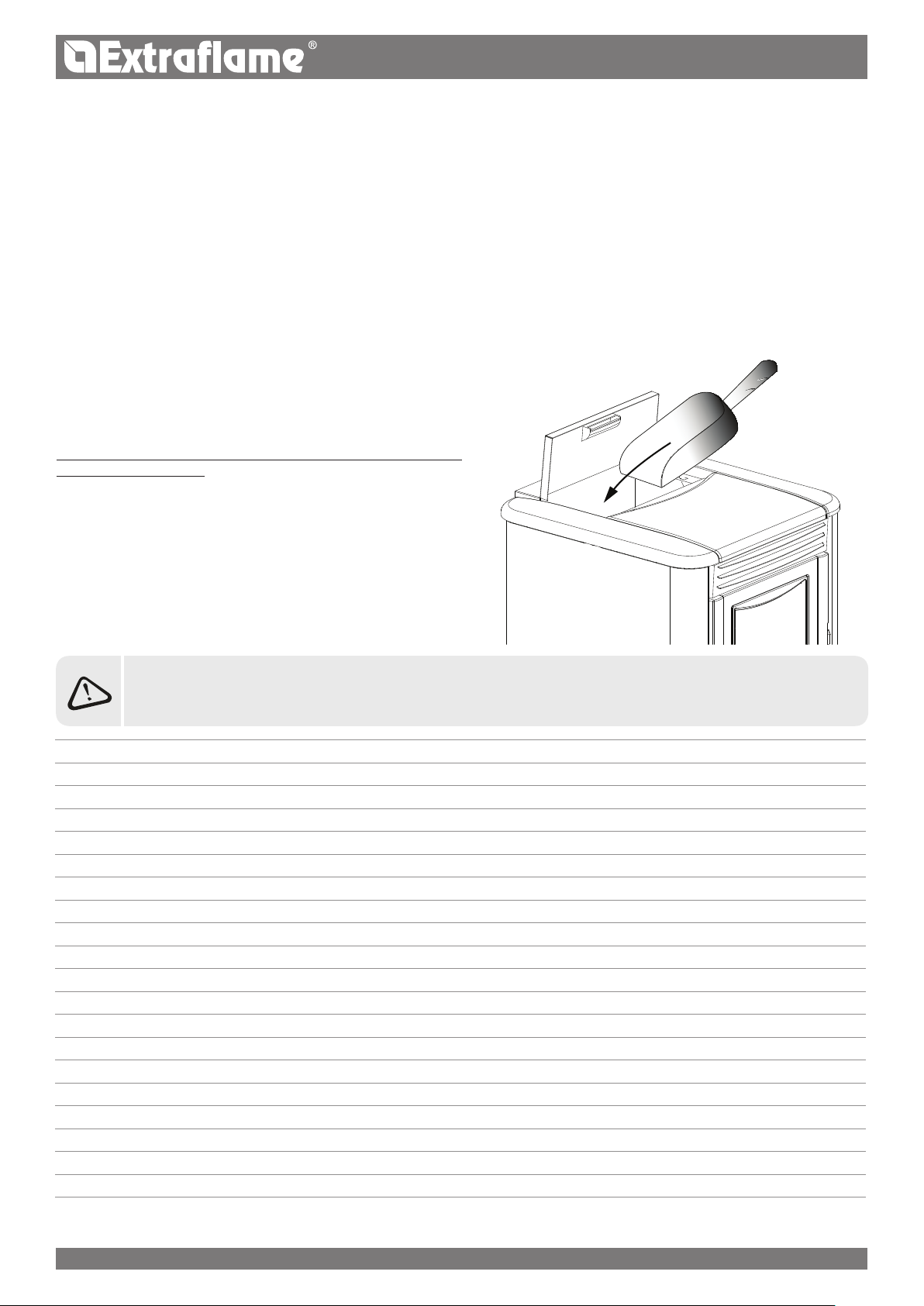
PELLET STORAGE
In order to ensure problem-free combustion pellets must be stored in
a dry place.
Open the tank lid and load the pellets using a scoop.
THE USE OF EXPIRED PELLETS OR ANY OTHER MATE RIAL WILL AFFECT THE FUNCTIONALITY OF YOUR
GENERATOR AND MAY LEAD TO THE TERMINATION OF THE WARRANTY AND CESSATION OF ANY ACCOMPANYING
RESPONSIBILITY ON THE PART OF THE MANUFACTURER
8
ENGLISH
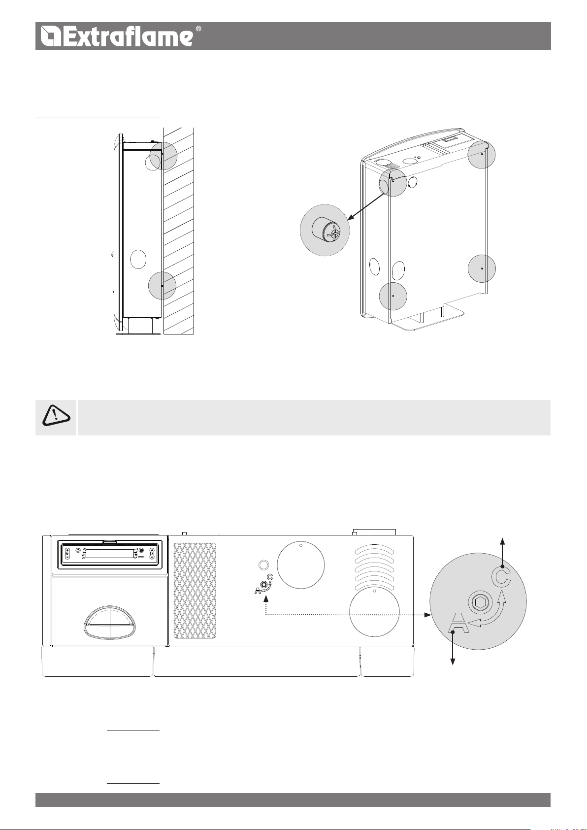
SOUVENIR AND ILENIA - ANNABELLA SPACERS
Models “ SOUVENIR” and "ILENIA - ANNABELLA" feature 4 spacers at the back which delimit the minimum distance to be maintained from any
rear support.
The spacers must not be removed.
HOT AIR DUCTING
The pipe used for ducting the hot air must have an internal diameter of 80 mm, be insulated and protected against heat loss.
INSTA LLATION OF THE RELEVANT PIPES USED FOR DUCTING THE HOT AIR MUST BE PERFORMED BY QUALIFIED
STAFF AND/OR THE MANUFACTURER'S TECHNICAL AFTER-SALES ASSISTANCE
SOUVENIR - ILENIA - ANNABELLA
Models “ SOUVENIR” and "ILENIA - ANNABELLA" can be ducted at the back (1), to the side (2) or at the top (3), for further details relating to
installation refer to the instruction sheet included in the machine.
There is the possibility to decide when to use the ducting by manually diverting the hot air ow, using a key, supplied, which can be inserted
in the relevant housing located on the upper part of the stove.
DUCTING INTO THE
ROOM
- SOUVENIR
By turning it counterclockwise (position "C") part of the air is conveyed into the ducting, by turning it clockwise
(position "A") the ducting is conveyed into the room.
It is possible to use single ducting as required.
- ILENIA - ANNABELLA
By turning it counterclockwise (position "C") the air is conveyed into the ducting, by turning it clockwise
(position "A") the air is conveyed into the room.
It is possible to use single ducting as required.
ENGLISH
9
Features:
ducting outlet diameter: 80 mm
maximum recommended ducting length 6m
it is not possible to thermostat the ducting
possibility to adjust the fan speed in percentage.
POSITION "C"
POSITION "A"
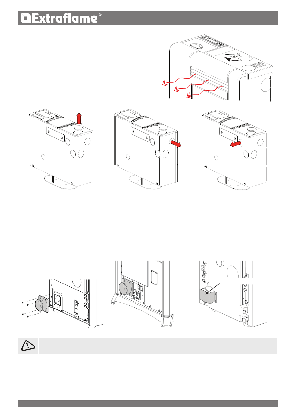
GRAZIOSA PLUS, IRMA PLUS, NOVELLA PLUS & SIBILLA PLUS
For GRAZIOSA PLUS, IRMA PLUS, NOVELLA PLUS & SIBILLA PLUS model it is mandatory to duct the hot air.
Features:
ducting outlet diameter: 80 mm
maximum recommended ducting length 6m GRAZIOSA PLUS, IRMA PLUS & SIBILLA PLUS
maximum recommended ducting length 8m NOVELLA PLUS
possibility to thermostat the ducting via an additional thermostat
possibility to adjust the fan speed in percentage.
The ducting extension is found in the accessory
pack inside the stove. It is mounted by means of
the 4 supplied screws.
NOVELLA PLUS
FOR THIS PRODUCT IT IS MANDATORY TO DUCT THE HOT AIR. IT IS NOT POSSIBLE TO DISABLE THE DUCTING MOTOR.
DO NOT COVER OR CLOSE THE DUCTING!
IRMA PLUS GRAZIOSA PLUS - SIBILLA PLUS
Remove the cover!
EMMA PLUS & TOSCA PLUS
The EMMA PLUS & TOSCA pLUS model oer the possibility to decide where to aim the hot air ow thanks to 2 gate valves moved by 2 levers
positioned inside the pellet tank, which must be activated via the poker supplied
(see gures below).
One can use both outlets on the back of the appliance
10
ENGLISH
Features:
ducting outlet diameter: 2x80 mm
maximum recommended ducting length 2m
it is not possible to thermostat the ducting
possibility to adjust the fan speed in percentage
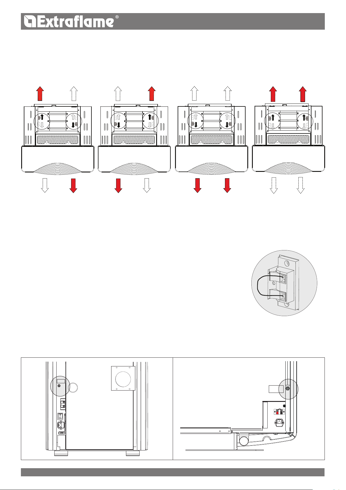
ADDITIONAL THERMOSTAT FOR DUCTING MOTOR CONTROL
For models with ducting motor there is also the possibility of thermostatting the motor itself. The connection of an external thermostat will
allow to control the ducting motor independently from stove functioning.
At this point just set the desired temperature on the thermostat; the thermostat will control the functioning of the second motor:
with temperature to be reached (closed contact) the second motor will follow the trend of
the stove.
when the temperature has been reached (open contact), it takes the ducting motor to 1st
speed and will be displayed by the ashing LED relating to the ducting motor.
The ducting thermostat clamp is tted with a jumper as standard.
See the example drawing to the side.
REARMS
The gures below illustrate the positions of the tank (85°C) rearms. Contact the qualied technician if one of the rearms should be triggered,
so as to verify the cause.
85C°
85C°
ENGLISH
11
 Loading...