

Page 1

en
FORCED VENTILATION PELLETS FIREPLACE INSERT
installation, use and maintenance manual
nl
OPEN HAARD PELLETS
handleiding voor installatie, gebruik en onderhoud
eolo - comfort 80
©2015 CADEL srl | All rights reserved – tutti i diritti riservati
Page 2

EN
Summary
1 MANUAL SIMBOLOGY ......................................... 3
2 DEAR CUSTOMER ................................................. 3
3 CAUTIONS ............................................................ 3
4 SAFETY REQUIREMENTS ..................................... 4
5 WARRANTY CONDITIONS .................................... 5
6 SPARE PARTS ......................................................... 6
7 WARNINGS FOR THE CORRECT DISPOSAL OF THE
PRODUCT ..................................................................... 6
8 PACKAGING AND HANDLING ........................... 6
8.1 PACKAGING ....................................................6
8.2 STOVE HANDLING ............................................ 6
9 CHIMNEY FLUE ..................................................... 6
9.1 INTRODUCTION ................................................ 6
9.2 CHIMNEY FLUE ..................................................7
9.3 TECHNICAL FEATURES ...................................... 7
9.4 HEIGHT-DEPRESSION ........................................ 8
9.5 MAINTENANCE ................................................. 8
9.6 CHIMNEY POT ...................................................9
9.7 CHIMNEY COMPONENTS ................................ 9
9.8 EXTERNAL AIR INLET ........................................10
9.9 CHIMNEY FLUE CONNECTION ...................... 10
9.10 EXAMPLES OF CORRECT INSTALLATION ...... 11
10 FUEL ................................................................... 12
10.1 FUEL ................................................................ 12
11 INSTALLATION ................................................... 13
11.1 INTRODUCTION .............................................13
11.2 OVERALL DIMENSIONS .................................13
11.3 GENERAL INSTALLATION ............................... 14
11.4 INSERT REMOVAL ..........................................15
11.5 INSERT FITTING ...............................................16
11.6 INSTALLATION WITH EXTERNAL COVER ....... 17
11.7 INSTALLATION ON EXISTING FIREPLACE ...... 19
11.8 ELECTRIC CONNECTION ..............................20
11.9
CONNECTION TO THE EXTERNAL THERMOSTAT ....
12 USE ..................................................................... 21
12.1 INTRODUCTION .............................................21
12.2 CONTROL PANEL ..........................................21
12.3 USER MENU .................................................... 22
12.4 IGNITION ........................................................ 23
12.5 STOVE ADJUSTMENT .....................................23
12.6 FAILED IGNITION............................................23
12.7 POWER FAILURE ............................................24
12.8 TEMPERATURE SETTING .................................24
12.9 FUME TEMPERATURE ......................................24
12.10 SWITCHING OFF ........................................... 24
12.11 CLOCK SETTING ........................................... 24
12.12 DAILY PROGRAMMING ..............................24
12.13 WEEK-END PROGRAMMING ..................... 24
12.14 WEEKLY PROGRAMMING ........................... 25
12.15 PELLET SUPPLY .............................................. 25
12.16 PELLET SENSOR ............................................. 25
12.17 REMOTE CONTROL ..................................... 25
21
13 SAFETY SYSTEM ................................................. 26
13.1 INTRODUCTION .............................................26
13.2 "BLACK OUT" ALARM ....................................26
13.3 "FUME PROBE" ALARM .................................. 26
13.4 "HOT FUME" ALARM ......................................26
13.5 "FAN FAILURE" ALARM ..................................26
13.6 "NO IGNITION" ALARM .................................27
13.7 "NO PELLET" ALARM ......................................27
13.8 "THERMAL SAFETY" ALARM ...........................27
13.9 "FAILURE DEPRESS" ALARM ........................... 27
13.10 "OPEN DOOR" ALARM ................................ 27
14 MAINTEINANCE ................................................. 27
14.1 INTRODUCTION .............................................27
14.2
BURNING POT AND ASH TRAY CLEANING ....
14.3 COMBUSTION CHAMBER CLEANING .......... 28
14.4 HOPPER AND AUGER CLEANING ................ 29
14.5 FUME CHAMBER CLEANING ........................ 29
14.6 FUME PIPE CLEANING ................................... 29
14.7 EXHAUST FAN CLEANING ........................... 30
14.8 FUME PASSAGES ANNUAL CLEANING ........ 30
14.9 FUME PIPES ANNUAL CLEANING .................31
14.10 GENERAL CLEANING ................................31
14.11 CLEANING OF PAINTED METAL PANELS .... 31
14.12 GASKET REPLACEMENT ............................... 31
14.13 GLASS CLEANING ........................................31
14.14 GLASS REPLACEMENT ................................. 31
15 IN CASE OF ANOMALY ...................................... 32
15.1 ALARMS .........................................................32
15.2 PROBLEM SOLVING ......................................34
16 TECHNICAL DATAS ............................................. 36
16.1 REPAIR INFORMATION ..................................36
16.2 FEATURES .......................................................38
27
2
EOLO - COMFORT 80
Page 3

EN
1
• The icons with the stylized gures indicates whom the subject dealt in the paragraph is addressed to (between
• WARNING symbols indicates an important note.
MANUAL SIMBOLOGY
the User and/or the Authorized Technician and/or the Specialized Stove-repairer).
USER
AUTHORISED TECHNICIAN
(ONLY to interpret or the Stove-manufacturer or the Authorized
Technician of Technical Assistance Service approved by the Stove-
manufacturer)
SPECIALIZED STOVE-REPAIRER
CAUTION:
READ CAREFULLY THE NOTE
CAUTION:
DANGER OR IRREVERSIBLE DAMAGE POSSIBILITY
2
• Our products are designed and manufactured in compliance with standards EN 13240 for wood stoves,
• Read carefully the instruction contained in this manual to obtain the best efciency.
• This instruction manual is an integral part of the product: make sure it is delivered with the appliance also in
• According to (EU) No. 305/2011 regulation, the " Declaration of Performance" is available online at the web
3
• All the pictures carried in this manual are only for indicative and explanatory purpose and could therefore
• The referring appliance is those you purchased.
• In case of doubts or difculties in the comprehension or for problems not described in this manual, please
DEAR CUSTOMER
EN 14785 for pellet stoves, EN 13229 for re places, EN 12815 for wood cooker stoves, C.P.R. 305/2011 for
manufacturing products, Re n.1935/2004 for materials and objects which are in contact with foods, Dir.
2006/95/CEE for low tension, Dir.2004/108/EC for Electromagnetic compatibility.
case of sold to others. In case of loss please ask a copy to your local Technical Assistance Service.
In Italy biomass system installation below 35 kW must comply with MD 37/08. Every qualied
installer who own these requirements, has to issue the certicate of conformity for the
installed system ("system" means: stove + chimney + air inlet).
sites www.cadelsrl.com / www.free-point.it.
CAUTIONS
slightly differ from your appliance.
promptly contact your distributor or installer.
EOLO - COMFORT 80
3
Page 4

EN
4
SAFETY REQUIREMENTS
• Installation, electrical connection, functional verication and maintenance must
only be performed by qualied or authorised personnel.
• Live electrical parts: disconnect the product from the 230V power supply before
performing any maintenance operation. Only power the product after completing
assembly.
• Special maintenance must only be performed by authorised and qualied
personnel.
• All local regulations, including those referring to national European standards, must
be respected during appliance installation.
• The manufacturer declines any responsibility in case of installation which are not
in compliance with current regulations, in case of a wrong room ventilation system,
in case of an electric connection which is not in compliance with regulations and in
case of a wrong use of the appliance.
• It is forbidden to install the stove in bedrooms, bathrooms and in rooms used for
storing combustible materials and in one-room ats.
• The installation in one-room ats is allowed if they are in sealed chamber.
• In any case the stove must not be installed in rooms where it can get in touch with
water or water splashes because this can cause burn hazards and short-circuit.
• Please check that the oor has an adequate load capacity. If the existing one does
not satisfy this requirement, appropriate measure should be provided (for example a
plate for distributing the load).
• For safety re regulations the distances from ammable or sensible to heat objects
(sofas, pieces of furniture, wooden covering, etc...) must be respected.
• If there are highly ammable objects (curtains, tted carpet, etc...), all these
distances must be further increased with 1 meter.
• The electrical cable must not get in touch with the fume exhaust pipe and nor with
every other part of the stove.
• The user, or whoever is operating the product, must read and fully understand the
contents of this installation and use guide before performing any operation. Errors or
incorrect settings can cause hazardous conditions and/or poor operation.
• The type of fuel to use is only the pellets.
• Do not use the appliance as waste inceneretor.
• Do not place laundry on the product to dry. Any clothes horses or similar objects
must be kept at a safe distance from the product. Fire hazard.
• It is forbidden to operate the product with the door open or the glass broken.
• It is forbidden to modify the appliance without authorization.
• Do not use ammable liquids during the ignition (alcool, petrol, oil, etc...).
• After a failed ignition the burning pot must be empty from the amassed pellets,
before starting the stove up again.
• The pellet hopper must always be closed with its own lid.
• Before of every intervention leave the re completely extinguish till the cooling and
always disconnect the plug from the electric socket.
• This appliance can be used by children aged from 8 years and above and persons
with reduced physical, sensory or mental capabilities or lack of experience and
knowledge if they have been given supervision or instruction concerning use of the
appliance in a safe way and understand the hazards involved. Children shall not play
with the appliance. Cleaning and user maintenance shall not be made by children
without supervision.
• Packaging are not toys and could cause suffocation or strangulation and other
health hazards! People (childreen included) with reduced mobility, psycological
deseases or without experience and knowledge must be kept away from packaging.
The stove is not a toy.
• Childreen must be constantly overseen in order to assure that they do not play
with the appliance.
4
EOLO - COMFORT 80
Page 5

EN
• During its running, the stove reaches high temperatures: keep away childreen and
animals and for your safety please use appropriate reproof devices, such as heatprotecting gloves.
• If the auger is blocked by a foreign object (for example: nails), and if it needs to
be cleaned, do not remove the hand rejector and do not touch the auger. Please
contact the Technical Assistance service.
• The hand rejector can be removed exclusively by an authorized technician.
• The chimney ue must be cleaned, since the soot and unburnt oil deposits reduce
its section so blocking the draught. In great quantities they can are up.
• If the pellets are of bad quality (if contains sizing agents, oils, varnishes, plastic
remains or if it is mealy), deposits will form along pellets drop pipe during the running.
When the stove is switched off, these remains could form little hot coals that rising
along the pipe could reach the pellets on the hopper burning them and creating a
thick and harmful smoke inside the room. Please always keep the hopper closed with
its own lid. If the pipe is sooty, please clean it.
• In case it would be necessary to extinguish the re emitted by the stove or by the
chimney ue, use a re-extinguisher or contact the remen. Do not use water to
extinguish the re inside the burning pot.
5
The company guarantees the product, with the exception of elements subject to normal wear listed below, for
a period of 2 (two) years from the date of purchase attested by:
• a document to serve as proof of purchase (invoice and/or receipt) that shows the name of the vendor and
• forwarding of the completed certicate of guarantee within 8 days of purchase.
Furthermore, the product must be installed and started by specialised personnel who must, where provided,
issue a declaration of conformity of the plant and of the proper functioning of the product, for the warranty to
be valid and effective.
We recommend testing the product before completion with the relative nishes (claddings, painting of walls,
etc.).
Installations not meeting the current standards, improper use and lack of maintenance as expected by the
manufacturer, void the product warranty.
The guarantee is valid on the condition that the instructions and warnings contained in the use and maintenance
manual are observed, and therefore the product is used correctly.
The replacement of the entire system or the repair of one of its components does not extend the guarantee
period, and the original expiry date remains unchanged.
The guarantee covers the replacement or free repair of parts recognised as being faulty at source due to
manufacturing defects.
To benet from the guarantee, in the event of a fault, the customer must have the guarantee certicate and
present it with the proof of purchase document to the Technical Assistance Ofce.
The guarantee does not cover malfunctions and/or damage to the appliance that arise due to the following
causes:
• Damage caused during transportation or relocation.
• All parts that develop faults due to negligence or improper use, incorrect maintenance, installation that does
• Incorrect dimensioning with regards to the use or faults in the installation or failure to adopt the necessary
• Improper overheating of the equipment, use of fuels not conforming to the types and quantities indicated in
• Further damage caused by incorrect user interventions in an attempt to x the initial fault.
• Worsening of the damage due to the continued use of the equipment by the user, once the defect has been
• In the presence of a boiler, any corrosions, incrustations or breaks caused by water ow, condensation,
• Inefciency of chimneys, ues or parts of the plant affecting the equipment.
• Damage caused by tampering with the appliance, atmospheric agents, natural disasters, vandalism,
• Failure to have the stove cleaned on an annual basis by an authorised technician or qualied personnel will
WARRANTY CONDITIONS
the date on which the purchase was made;
not comply with the manufacturer's instructions (always refer to the installation and use manual provided with
the appliance).
devices to guarantee proper execution.
the instructions provided.
noticed.
hardness or acidity of the water, improperly performed descaling treatments, lack of water, mud or limescale
deposits.
electrical discharges, res, faults in the electric and/or hydraulic system.
result in the loss of the warranty.
Also excluded from this guarantee are:
• Parts subject to normal wear such as gaskets, glass, claddings and cast iron grids, painted, chrome-plated or
gilded parts, handles and electric cables, bulbs, indicator lights, knobs, all parts which can be removed from
the hearth.
EOLO - COMFORT 80
5
Page 6

EN
• Variations in colour of the painted or ceramic/serpentine parts and craquelure ceramics as they are natural
characteristics of the material and product use.
• Masonry work.
• Plant parts (if present) not supplied by the manufacturer.
Any technical interventions on the product to eliminate the above-said defects and consequent damages must
be agreed upon with the Technical Assistance Centre, who reserves the right to accept the relative appointment
or not. However, said interventions will not be carried out under warranty but as technical assistance to be
granted at part of any eventual and specic agreed conditions and in accordance with the fee in force for the
work to be carried out.
The user will also be charged for any costs incurred to remedy the incorrect technical interventions, tampering
or damage to the appliance, not attributable to original faults.
Save for the legal or regulatory limits, the guarantee does not cover the containment of atmospheric and
acoustic pollution.
The company declines all liability for any damage which may be caused, directly or indirectly, to persons,
animals or objects as a consequence of non compliance with any prescription specied in the manual, especially
warnings regarding installation, use and maintenance of the appliance.
6
For each repair or adjustment which should be necessary, please contact the dealer where you purchased your
stove or your nearest Technical Assistance Service, specifying:
• Appliance model
• Serial number
• Type of problem
Use only original spare parts which you can nd at our Technical Assistance Services.
7
The owner is the sole party responsible for demolishing and disposing of the product. This must be performed in
compliance with laws related to safety and environmental protection in force in his/her country.
At the end of its working life, the product must not be disposed of as urban waste.
It must be taken to a special differentiated waste collection centre set up by the local authorities or to a retailer
that provides this service.
Separating and recycling prevents potential negative effects on the environment and health (often caused by
inappropriately disposing of product parts). It also allows materials to be recovered in order to obtain signicant
savings in energy and resources.
8
SPARE PARTS
WARNINGS FOR THE CORRECT DISPOSAL OF THE PRODUCT
PACKAGING AND HANDLING
8.1 PACKAGING
• The packaging is made up of recyclable cardboard boxes according to RESY standards, recyclable
expanded polystyrene inserts and wooden pallets.
• All packaging materials can be re-used for a similar use or eventually discharged as waste assimilable to the
municipal solid ones, in accordance with current regulations.
• After having removed the packaging please assure you about the integrity of the product.
8.2 STOVE HANDLING
Both whether the stove is packed or not it is necessary to observe the following instructions for handling and
transporting the stove from its sale point to its installation point and for any future movements:
• The stove must be handled with idoneous means paying attention to the existing safety regulations;
• do not turn the stove upside down and/or upset it on one side, but keep it in vertical position or as accorded
with the constructor instructions;
• if the stove is made up of ceramic, stone, glass or any particularly fragile material components, all must be
moved with the utmost care.
9
CHIMNEY FLUE
9.1 INTRODUCTION
This chapter about the Chimney Flue has been drawn up in cooperation with Assocosma (www.assocosma.org)
and is based on European Standards (EN 15287 - EN 13384 - EN 1856 - EN 1443 - UNI 10683:2012).
It provides instructions for a good and correct execution of the chimney ue but it does not absolutely replace
the current standards which the qualied manufacturer/installer should comply with.
6
EOLO - COMFORT 80
Page 7

EN
Please check with your local authorities if exists any restrictive regulation which regards the
combustible air inlet, the fumes exhaust system, the chimney ue and the chimney pot.
The company declines any responsibility regarding the bad running of the stove if it is due to the use of a no
correctly dimensioned chimney ue which does not respect current regulations.
9.2 CHIMNEY FLUE
Fig. 1 - Chimney Flues
LEGEND Fig. 1 page 7
1 Chimney ue with insulated stainless-steel pipes
2 Chimney ue on the existing chimney
3 Inspection plug
4 Inspection door
5 ≥ 3,5 mt
• The chimney ue or chimney is of great importance for the correct running of the heating appliance.
• It is fundamental that the chimney ue is perfectly built and always maintained with a perfect efciency.
• The chimney ue must be sole (see Fig. 1 page 7) with insulated stainless-steel pipes (1) or installed on the
existing chimney ue (2).
• Both this solutions must be endowed with an inspection plug (3) and/or an inspection door (4).
9.3 TECHNICAL FEATURES
EOLO - COMFORT 80
Fig. 2 - Inclined roof
7
Page 8

EN
LEGEND Fig. 2 page 7
1 Height over the ridge of the roof = 0,5 mt
2 Roof inclination ≥ 10°
3 90°
4 Measured distance at 90° from the roof surface = 1,3 mt
• The chimney ue must be sealed from fumes.
• It must have a vertical run without narrowing. It must be realized with fume and condensation resistant
materials with thermal insulation and able to last against usual mechanical stresses.
It must be insulated to avoid condensation and to reduce fume cooling effects.
• The stove must be spaced out from fuels or ammable materials with an air gap or with insulating materials.
Check the distance with the chimney manufacturer.
• The chimney entrance must be placed in the same room where the appliance is installed or otherwise in
the adjacent room and it must be provided with a solid and condensation collection chamber under the
entrance, accessible through the sealed metal gate.
• Auxiliary exhaust fans cannot be installed neither along the chimney nor on the chimney pot.
• The inner section of the chimney ue can be round (the best one) or square and the jointed sides must have
a minimum radius of 20 mm.
• The section dimension must be:
• minimun Ø100 mm (for stoves up to 8.5 kw)
• minimun Ø120 mm (for stoves to 9 kw up)
• Made the efciency of the chimney ue overhauled by an expert stove-repairer and if necessary cover the
chimney ue with materials in compliance with current regulations.
• The ue system must be placed on the roof.
• The chimney ue must be provided CE in accordance with EN 1443 regulation. Please nd attached an
example of label:
Fig. 3 - Example of label
9.4 HEIGHT-DEPRESSION
The depression (draught) of a chimney ue depends also on its height. Check the depression with the values
provided at FEATURES page 38. Minimum height 3,5 meters.
9.5 MAINTENANCE
• The fumes extraction pipes (fumes conduit + chimney ue + chimney pot) must always be cleaned, scrubbed
and checked by an expert stove-repairer, in compliance with current regulations, with the instructions of the
stove-manufacturer and the directives of your insurance company.
• In case of doubts, please follow the most restrictive regulations.
• Have your chimney ue and chimney pot checked and cleaned by an expert chimney sweep at least once
a week. The chimney sweep has to release a written declaration about the security of the system.
• Not cleaning compromise safety.
8
EOLO - COMFORT 80
Page 9

EN
9.6 CHIMNEY POT
Fig. 4 - Anti-wind chimney pots
The chimney pot is important for the correct running of the heating appliance:
• We recommend using an anti-wind chimney pot, see Fig. 4 page 9.
• The hole width for fumes exhaust must be the double of the chimney ue width and tted in a way that the
fume exhaust is assured also in case of wind.
• It should prevent the inltration of rain, snow and animals.
• The outlet height in the atmosphere must be away from the reux area caused by the roof structure or by
obstacles laying nearby (see Fig. 2 page 7).
9.7 CHIMNEY COMPONENTS
EOLO - COMFORT 80
Fig. 5 - Chimney components
LEGEND Fig. 5 page 9
1 Chimney pot
2 Fume outlet
3 Chimney ue
4 Termal insulation
5 External wall
6 Chimney union
7 Fume pipe
8 Heat generator
9 Inspection door
10 T-union with inspection plug
9
Page 10

EN
9.8 EXTERNAL AIR INLET
Fig. 6 - Direct air inow Fig. 7 - Indirect air inow
LEGEND Fig. 6 page 10 - Fig. 7 page 10
1 Room to ventilate
2 Adjacent room
3 External air inlet
4 Cleft under the door
• The room must be endowed with an external air recycling for a good climate in your ambient.
• The air inow from outside to the inner occurs directly, through an opening on the external wall of the room
(see Fig. 6 page 10); otherwise it occurs indirectly by air suction from rooms adjacent to the one to ventilate
(see Fig. 7 page 10).
• Bedrooms, garages, and store of ammable materials are excluded.
• The air inlet should have a total net surface of 80 sqcm2: the aforesaid surface is to widen if inside the room
there are other activated appliances (for example: electric ventilators for foul air suction, cooker hoods, other
stoves, etc...) which depress the environment.
• At switched on appliance it is necessary to check that the pressure fall between the room and the outside
does not exceed 4,0 Pa value: if necessary widen the air inlet (EN 13384).
• The air inlet must be realized at a height close to the oor with an external grid against birds. In such a way it
cannot be obstructed by any object.
• In case of installation with sealed-chamber the air inlet is not necessary.
9.9 CHIMNEY FLUE CONNECTION
Your pellet stove works through a fume draught forced by a fan. It is obligatory to check that all pipes are
realized in compliance with the following regulation on material selection: EN 1856-1, EN 1856-2 e UNI/TS 11278.
All must be effected by specialized personnel or companies as provided by UNI 10683:2012.
• The connection between the appliance and the chimney ue should be short in order to favor the draught
and to avoid condensation in the pipes.
• The fume conduit should be equivalent or longer than the outlet joint ones (Ø 80 mm).
• Some stove models are endowed with a lateral and/or back exhaust. Check that the unused exhaust is
sealed with the plug given with standard equipment.
SYSTEM TYPE Ø80 mm PIPE Ø100 mm PIPE
Minimum vertical length 1,5 mt 2 mt
Maximum length (with 1 union) 6,5 mt 10 mt
Maximum length (with 3 unions) 4,5 mt 8 mt
Maximum number of unions 3 3
Level section (minimum inclination 3%) 2 mt 2 mt
Installation at a height above 1200 m a.s.l. NO Obligatory
• Use a plate pipe for stoves of Ø80 mm or Ø100 mm depending on the type of system and with silicone gaskets.
• It is forbidden to use metal, bre cement or aluminium exible pipes.
• For change of direction it is obligatory always to use a union (with angle > 90°) with inspection plug which
enables an easy periodic cleaning of the pipes.
• Please assure you that after the cleaning the inspection plugs are sealed with its efcient gasket.
• It is forbidden to connect more appliances to the same fume conduit.
• It is forbidden to convey in the same fume conduit exhausts from overhanging cooker hoods.
• It is forbidden to exhaust ue gases directly from the wall towards the outside and closed spaces also at open
10
EOLO - COMFORT 80
Page 11

EN
top.
• It is forbidden to connect any other appliance (wood stoves, cooker hoods, boilers, etc...).
• The fume conduit must be placed at a distance of minimum 500 mm from ammable or heat-susceptible
components.
9.10 EXAMPLES OF CORRECT INSTALLATION
Fig. 8 - Example 1
LEGEND Fig. 8 page 11
1 Insulating material
2 Reduction from Ø100 to Ø80 mm
3 Inspection plug
4 Minimum safety distance = 0,5 mt
• Chimney ue installation Ø100/120 mm with an enlarged drilling for pipe transit.
Fig. 9 - Example 2
LEGEND Fig. 9 page 11
1 Insulating material
2 Inspection plug
3 Chimney inspection entrance
4 Minimum safety distance = 0,5 mt
5 Inclination ≥ 3°
6 Level section ≤ 1 mt
• Old chimney ue with an inserted pipe of minimum Ø100/120 mm and with an external door which enables
the chimney cleaning.
EOLO - COMFORT 80
11
Page 12

EN
Fig. 10 - Example 3
LEGEND Fig. 10 page 12
1 Insulating material
2 Inspection plug
3 Minimum safety distance = 0,5 mt
• External chimney ue entirely made up of insulated stainless steel pipes, i.e. with double wall of minimum
Ø100/120 mm: all must be rmly attached to the wall. For chimney against wind effects please (see Fig. 4
page 9).
• Ducting system through T-unions which enables an easy cleaning without disassembling the pipes.
We recommend to check with your chimney ue manufacturer the safety distances which
must be respected and the type of insulating material. The aforesaid regulations are valid
also for holes made on the wall (EN 13501 - EN 13063 - EN 1856 - EN 1806 - EN 15827).
10
FUEL
10.1 FUEL
• Use top-quality pellets because they have inuence in the caloric value and in ash remains.
• Pellets features are: dimension Ø6-7mm (D06 Class), maximum lenght 40 mm, caloric value 5kWh/kg, humidity
≤ 10%, ash remains ≤ 0,7%, they must be correctly pressed and not much mealy, without sizing agents, resins
and other additives (it is advisable to use pellets in compliance with the regulation EN14961-2 type ENplus-A1).
• Not adequate pellets cause a bad combustion, a frequent burning pot obstruction and exhaust conduits
obstruction. Further it decreases the caloric value, soils the glass and increases consumptions and ash and
unburnt granules quantity.
Humid pellets cause a bad combustion and running, so please assure you that they are
stored in dry places and far at least one meter from the stove and/or any other source of
heat.
• It is advisable to try different type of pellets available on the market and to choose that which gives the best
performance.
• The use of bad quality pellets can damage the stove so that the warranty and manufacturer liability fall.
• On all our product are used high-quality materials such as stainless-steel, steel, cast iron, etc... These materials,
before being sold on the market, are tested in laboratory, but despite this on the components which enable
the pellets ow (auger) there could exist minimum differences in the material used, in roughness and porosity,
which could generate usual variations in fuel transportation (pellets), causing a ame raising or drapping with
a possible switching off at lower powers.
• Depending on the type of pellets it could be necessary a parameters adjustment, please contact an
Authorized Assistance Service.
12
EOLO - COMFORT 80
Page 13

EN
11
INSTALLATION
11.1 INTRODUCTION
• The assembly position must be chosen depending on environment, outlet, chimney ue.
• Check with local authorities if there are any restrictive regulations which regard the combustible air inlet,
room ventilation, fume exhaust system together with chimney ue and chimney pot.
• Check if there is the combustible air inlet.
• Check the probable presence of other stoves or appliances which could depress the room (see EXTERNAL
AIR INLET page 10).
• Check at switched on stove if there is the presence of CO in the room.
• Check if the chimney has the necessary draught.
• Check if during the fume passage all has been executed in safety (probable fume losses and distances from
ammable materials, etc.…).
• The installation of the appliance must enable an easy access for appliance, fume exhaust pipes and chimney
ue cleaning.
• The installation must enable en easy access to the electric connection plug.
• To install more appliances, the external air inlet must be correctly dimensioned (see EXTERNAL AIR INLET page
10).
11.2 OVERALL DIMENSIONS
EOLO - COMFORT 80
Fig. 11 - General dimensions
13
Page 14
EN
LEGEND Fig. 11 page 13
1 Door for loading pellet
2 Extractable pellet insert
3 Adjustable legs
4 Insert supporting frame
5 Fume exhaust Ø 80 mm
6 Adjustable height of the legs (min-max)
7 Hot air outlet (upper and lateral)
8 Combustible air inlet and cooling
9 Wall cutting dimension (plasterboard/bricks)
11.3 GENERAL INSTALLATION
Fig. 12 - General installation
LEGEND Fig. 12 page 14
1 Fireplace insert
2 Minimum lateral distance = 240 mm
3 Minimum rear distance = 190 mm
4 Minimum front distance = 1000 mm
5 Minimum thickness of insulating material = 40 mm
• Please check that the oor has an adequate load capacity. If the existing one does not satisfy this requirement,
appropriate measure should be provided (for example a plate for distributing the load).
• It is obligatory to install the stove away from walls and/or pieces of furniture, with a minimum air ow of 240
mm on the sides and 190 mm on the back, to enable an ecient appliance cooling and a good distribution
of heat in the room (see Fig. 12 page 14).
• For safety re regulations the distances from ammable or sensible to heat objects (sofas, pieces of furniture,
wooden covering, etc...) must be respected, has described in Fig. 12 page 14.
The probable insulating material to use must have the following technical features:
CARATTERISTICHE VALORI
Material thickness 40 mm
Screening temperature 1000 °C
Density 245 Kg/m3
Shrinkage at referring temperature (12h) 1,3 % /1000 °C
Cold crushing strenght 1,4 MPa
Bending strenght 0,5 MPa
Thermal expansion coefcient 5,4x10⁻⁶ m/mK
Specic heat 1,03 Kj/kgK
14
EOLO - COMFORT 80
Page 15
CARATTERISTICHE VALORI
200 °C 0,07 W/mK
EN
Thermal conductivity at medium temperature
400 °C 0,10 W/mK
600 °C 0,14 W/mK
800 °C 0,17 W/mK
• If there are highly ammable objects (curtains, tted carpet, etc...), all these distances must be further
increased with 1 meter.
• If the oor is made up of ammable material two solutions are possible:
• build a protection (steel plate, refractory, marble...) made up of no ammable material;
• otherwise the insert must be raised at a minimum height of 200mm from the oor (adjusting legs' lenght).
• If the walls are made up of ammable materials, check the safety distances (see Fig. 12 page 14).
• At maximum power check that the wall temperature does not ever exceed 80°C. If it would be necessary
please install a re resistant plate on the concerned walls.
• In some countries also masonring load-bearing walls are considered ammable.
11.4 INSERT REMOVAL
In case of settled on guides insert removal there is the risk of overturning!
Disassembly operations must always be executed with the aid of 2 people!
Fig. 13 - Retainers
• Unhook the 2 yellow retainers (see Fig. 13 page 15) and extract half of the insert from its frame.
Fig. 14 - Insert xing front screw Fig. 15 - Insert xing rear screw
• Unscrew the 2 xing screw on both insert sides, as shown in Fig. 14 page 15 and Fig. 15 page 15.
EOLO - COMFORT 80
15
Page 16

EN
Fig. 16 - Hand grips
• Through the 2 hand grips (see Fig. 16 page 16) extract the whole insert and, after having slightly lifted it,
remove it from its guides.
• Lean the insert body on a rm plane (such as the oor).
11.5 INSERT FITTING
In case of insert tting on the guides there is the risk of overturning!
Assembly operations must always be executed with the aid of 2 people!
Fig. 17 - Guides extraction
• Extract the 2 guides completely from the frame (as shown in Fig. 17 page 16).
16
Fig. 18 - Hand grips Fig. 19 - Insert on guides tting
EOLO - COMFORT 80
Page 17
EN
• With the aid of the hand grips (see Fig. 18 page 16) lift the insert and set it on the frame guides Fig. 19 page
16.
Fig. 20 - Insert xing rear screw Fig. 21 - Insert xing front screw
• Screw the 2 xing screws on both insert sides, as shown in Fig. 20 page 17 and Fig. 21 page 17.
• Push the insert inside the frame.
11.6 INSTALLATION WITH EXTERNAL COVER
• It is possible to cover the insert with your liking cover respecting the correct execution as described in GENERAL
INSTALLATION page 14 and following the under mentioned instructions.
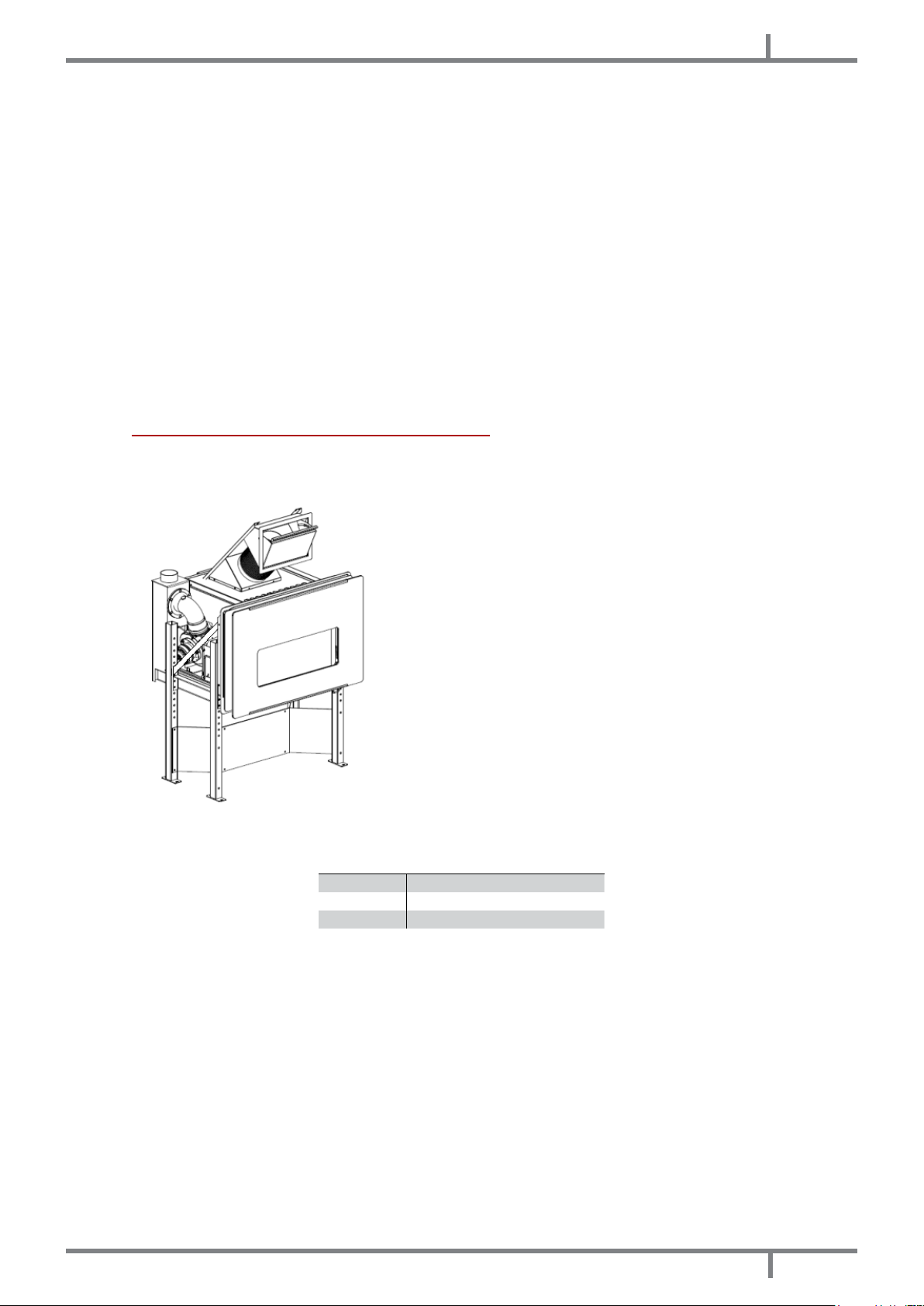
Fig. 22 - Complete structure Fig. 23 - Divided structure
LEGEND Fig. 23 page 17
1 Supporting legs
2 Fire place insert frame
3 Fire place insert
• Remove the insert as decribed in INSERT REMOVAL page 15.
EOLO - COMFORT 80
17
Page 18

EN
Fig. 24 - Fixing positions
• Fix the legs to the oor and lift the insert frame till the desired height by adjusting the legs (H 55÷660 mm) and
then block it with screws on the tting guides (see picture Fig. 24 page 18).
• It is obligatory to x the supporting frame legs at the base with metal plugs able to bear a weight of 50 kg for
leg.
In case of insert extraction xed on guides there is the risk of overturning!
Check if the insert frame is xed to the oor.
18
Fig. 25 - Installation with cover
EOLO - COMFORT 80
Page 19

LEGEND Fig. 25 page 18
1 Ceiling to protect
2 Ceiling plaster to protect from heat
3 Ventilation grid with a minimum entrance of 400 cm
4 Self-supporting metal frame
5 Combustible air outlet
6 Pellet load entrance
7 Lower air grid with a minimum entrance of 400 cm
8 Floor protecting plate
9 Outlet clutch Ø80 mm
10 Fume pipe Ø80 mm with a minimum vertical lenght of 1 mt
11 Chimney ue of minimum Ø120 mm
12 Sealed chimney ue's inspection door
13 Wall
14 Floor
15 Ceiling with wooden beam
16 Fireplace insert
17 Insulating between wall and fume pipe of minimum 200 mm on the whole diameter
18 Combustible air inlet
19 Minimum distance between the wooden beams and the fume pipe = 0,5 mt
2
for natural hot convective air outlet
2
for natural cool convective air inlet
• Build a metal frame for supporting cover panels (4).
• Do not discharge the metal structure weight on the insert frame.
• Cover the metal frame with panels made up of no ammable materials.
EN
Made a cleft of min. 400 cm2 on the lower (7) and upper (3) parts of the panels for the inner
air recycling.
• The pellet loading can occur by extracting the insert at switched off appliance, otherwise through the
installation of a loading trap door (6).
• The loading trap door can be frontally or laterally installed, extending the exible pipe Ø160 mm according
to your needs.
11.7 INSTALLATION ON EXISTING FIREPLACE
• It is possible to build the insert into an existing replace respecting the distances and the correct execution as
described by GENERAL INSTALLATION page 14 and following the below mentioned instructions.
• Remove the replace insert as described in INSERT REMOVAL page 15.
• Fix the legs at the lowest height (H 55 mm) and block them with screws on its tting guides.
• It is obligatory to x the leg of the supporting frame at the base with metal plugs able to bear a weight of 50
kg for leg.
In case of xed on guides insert extraction there is the risk of overturning!
Check if the insert frame is correctly xed to the base.
Check if the upper hot air outlet is not choked, see Fig. 26 page 20.
Make a cleft of 400 cm2 on the lower and upper part of the replace for the inner air
recycling.
• The pellet loading can occur by extracting the insert at switched off appliance, otherwise through the
installation of a loading trap door (6).
• The loading trap door can be frontally or laterally installed, extending the exible pipe Ø160 mm according
to your needs.
EOLO - COMFORT 80
19
Page 20

EN
Fig. 26 - Installation on the existing replace
LEGEND Fig. 26 page 20
1 Ceiling to protect
2 Ceiling plaster to protect from heat
3 Ventilation upper grid minimum entrance 400 cm
4 Hot air deector
5 Combustible air inlet
6 Fireplace's re plate
7 Lower air grid with minimum entrance 400 cm
8 Ventilation cleft of 400 cm2 for convective cool air recycling
9 Outlet clutch Ø80 mm
10 Fume pipe Ø80 mm with minimum vertical lenght of 1 mt
11 Chimney ue > Ø120 mm
12 Fume pipe Ø100 mm
13 Wall
14 Floor
15 Ceiling with wooden beams with a minimum distance from the fume pipe = 0,5 mt
16 Fire place insert
17 Pellet loading entrance
18 Locking ring
2
for natural hot convective air outlet
2
for natural cool convective air inlet
11.8 ELECTRIC CONNECTION
Warning: the appliance must be installed by an authorized technician!
• The electric connection occurs through a cable with plug put in an electric socket which is able to support
charge and tension specic of every model, as described in the technical datas table (see FEATURES page
38).
20
EOLO - COMFORT 80
Page 21

EN
• The plug must be easily accessible when the appliance is installed.
• Please further assure you that your network is endowed with an efcient earth connection: if it does not exist
or if it is not efcient, please endow you with one in compliance with the law.
• Connect the supply cable rst on the back of the stove and then at a wall electric socket.
• Do not use extension cables.
• If the feeder cable is damaged, it must be replaced by an authorized technician.
• When the stove is not going to be used for a long period of time, it advisable to remove the plug from the
socket on the wall.
11.9 CONNECTION TO THE EXTERNAL THERMOSTAT
The stove works through a thermostat probe placed in its inner. If you desire, the stove can be connected to an
external room thermostat. This operation must be executed by an authorized technician.
• External thermostat: "SET TEMP ROOM" a temperature which is round 7°C.
• External chronothermostat: "SET TEMP ROOM" a temperature which is round 7°C and desable the chrono
functions from the menu 03-01 "CHRONO ENABLE" ("OFF").
12
USE
12.1 INTRODUCTION
To have the best performance with the lowest consumption please follow the here descripted instructions.
• The lightning of the pellets occurs very easily if the installation is correct and if the chimney ue is efcient.
• Switch on the stove at Power 1 for at least 2 hours in order to enable the materials which make up the boiler
and the replace to adjust the inner springing stress.
• Oily plant waste and lacquers can cause smells and smoke during the rst working hours: it is advisable to
ventilate the room because they could be noxious to people and animals.
• By using the stove the varnish inside the combustion chamber could be subjected to alterations. This
occurrence can be attributed to different reasons: an excessive stove overheating, the presence of chemical
agents in bad quality pellets, bad chimney draught, etc. Therefore varnish endurance in the combustion
chamber cannot be guarantee.
Set values from 1 to 5 are dened by the manufacturer and they can be changed only by
an authorized technician.
12.2 CONTROL PANEL
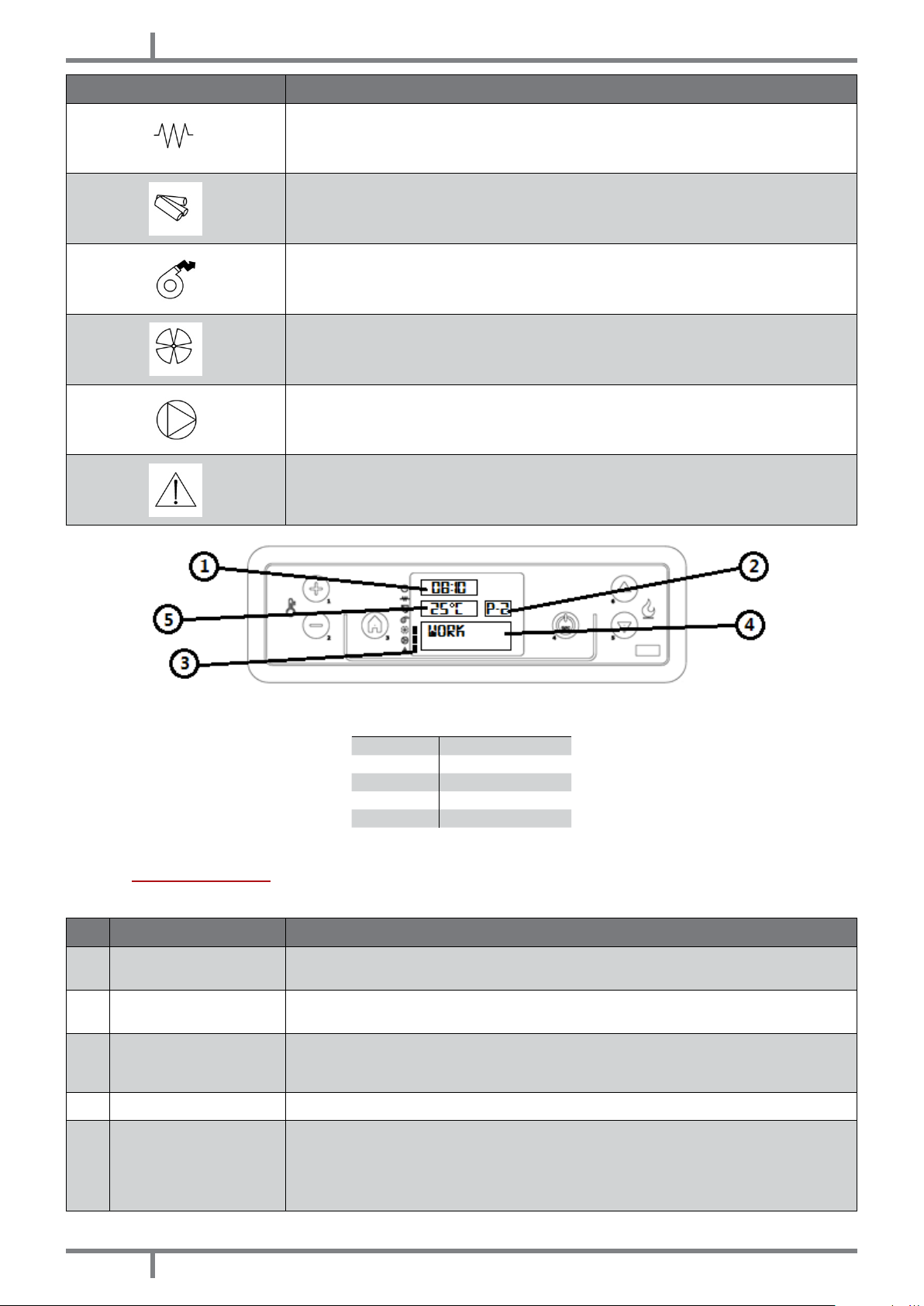
PANEL ELEMENT DESCRIZIONE
P1 e P2: when you are in set temperature mode the thermostat values increase
or decrease from min. 6°C to max. 40°C. Keeping pressed P2 you check the fume
temperature at outlet. Both have programming functions.
EOLO - COMFORT 80
P3: enables the access to temperature set and to User and Technician parameters
menu.
P4: ignition and shut down, unblocking from probable alarms and exit from programming.
P5 e P6: increase and decrease the caloric power from 1 to 5.
Crono: activated time schedule.
21
Page 22
EN
PANEL ELEMENT DESCRIZIONE
Sparking plug: activated ingnition.
Auger: activated.
Fume extractor: activated.
Exchanger fan: activated.
-
Alarm: activated.
Fig. 27 - LCD control display
LEGEND Fig. 27 page 22
1 Time
2 Power
3 Condition
4 Message
5 Temperature
12.3 USER MENU
Pressing P3 you have access to user parameters running. To slide them press P5 and P6 keys. It will appear:
POS. REFERENCE DESCRIZIONE
FAN ADJUST
1
(supplemetary)
2 SET CLOCK
3 SET CHRONO
4 SELECT LANGUAGE Press P3 key and with P1 and P2 keys select the desired language.
5 STAND-BY MODE
Module not supported from this type of stove.
Set date and time. The board is endowed with a lithium battery which enables 3/5 years
range. See |CLOCK SETTING page 24.
Press P3 key: it appears “CHRONO ENABLE”. Press P3 again and with P1 and P2 keys put
in "OFF" or "ON". For daily, weekend or weekly setting, see |DAILY PROGRAMMING page
24. ATTENTION: do not activate if STAND-BY mode is active!
If the settled room temperature has exceeded for more than 10 minutes, this mode
activates a function for shut down mode. If the room temperature has decrease of more
than 2°C, the stove switches on automatically, starting from |IGNITION page 23 . Press
P3 key and with P1 and P2 keys put in "OFF" or "ON" mode. ATTENTION: do not activate if
CHRONO function is active!
22
EOLO - COMFORT 80
Page 23

POS. REFERENCE DESCRIZIONE
EN
BUZZER MODE (acoustic
6
alarm)
7 INITIAL LOAD
8 STOVE STATE
9 TECHNICA SETTING Only for Autorized Technician
10 FLAME SETTING Enables to adjust the ame depending on chimney ue draught.
Press P3 key and with P1 and P2 keys put in "OFF" or "ON".
At the rst ignition of the stove, the auger is completely emty. If necessary have a
preloading pressing P3 key, then P1 for start-up and P4 to stop.
Displays all parameters connected to stove state: this is the menu for Autorized
Technician.
12.4 IGNITION
We remind you that the rst ignition must be executed by authorized and skilled technical personnel who checks
that all is installed in compliance with current regulations and veries stove's efciency.
• If inside the combustion chamber there are booklets, manuals, etc.… please remove them.
• Check if there are pellets in the hopper.
• Check that the door is correctly closed.
• Check that the plug is correctly put into the electric socket.
• Before starting up the stove, please assure you that the burning pot is clean.
• To start up the stove, keep pressed P4 key for little while till it appears “START” and then “PREHEATI WAIT"
which starts the preheating of the ignition resistance. After 2 minutes, the display shows “PELLET LOAD, FIRE
WAIT” when the auger load the pellet and the heating of the resistance goes on. When the temperature is
sufciently high (after about 7-10 minutes), the ignition has occured and the display shows “FLAME PRESENT”.
• When “FLAME PRESENT” stage has nished, the control unit enters on "WORK” mode and displays the selected
caloric power and room temperature. It is in this stage that P5 and P6 keys adjust the power from 1 to 5. If
room temperature exceeds the limit established during the setting, the caloric power falls at the minimum
displaying “WORK, MODULAT”. When the room temperature returns below the selected temperature, the
stove returns to the set power.
12.5 STOVE ADJUSTMENT
The stove is set in compliance with chimney ue and used pellets data, according to technical characteristics
(see FEATURES page 38). If the data do not correspond, the technician can set the stove.
• If the pellets is small in size and with a greater caloric power, (for example because of encrusted re pot)
decrease the pellet drop through the menu "FLAME SETTING", press P3 key "PELLET TYPE", press again P3 "PELLET
LOAD" and with P2 key decrease the pellet quantity from -1 (i.e. -2%) to -9 (i.e. -18%).
• If the chimney ue has a lower draught (for example because of a weak ame or sooty glass) increase the
fume motor revolutions through the menu "FLAME SETTING", press P5 key "CHIMNEY TYPE", press P3 key "FUMEEXT, CHIMNEY" and with P1 key increase the exhaust fan from +1 (i.e. +5%) to +9 (i.e. +30%).
• If the chimney ue has a greater draught (for example because of pellet fall from the burning pot) decrease
the exhaust fan revolutions from -1 to -9.
Pay attention to positive and negative values.
12.6 FAILED IGNITION
If the pellets do not burn, the failed ignition will be indicated by the alarm "NO IGNITION"
• If the room temperature is lower than 10°C, the plug is not able to bear the ignition stage. To support it please
insert some pellets in the burning pot and a piece of burning relighter igniter material on the pellets (for
example relighters cubes).
After a failed ignition the burning pot must be empty from the amassed pellets, before
starting up again the stove.
• Too much pellets in the burning pot, or humid pellets, or sooty burning pot make ignition difcult and create
dense white smoke which is harmful to health and can cause explosions on the combustion chamber. It is
therefore necessary not to stand in front of the stove during ignition stage if dense white smoke is present.
EOLO - COMFORT 80
23
Page 24

EN
If after some months the ame appears weak and/or orange colored or the glass tends to
blackens and the burning pot to become encrusted, clean the stove, clean the fume pipe
and the chimney ue.
12.7 POWER FAILURE
• After a black-out off less than 5 seconds, the stove returns to the set power.
• After a black-out of more than 5 seconds, the stove enters the stage “COOLING WAIT". At the end of cooling
stage, it starts automatically up with the different stages (see IGNITION page 23)
12.8 TEMPERATURE SETTING
• To modify the room temperature, it is sufcient to press P1 and P2 keys according to the desired temperature
when the display shows "SET TEMP ROOM".
• To display the set temperature, press P1 key.
12.9 FUME TEMPERATURE
To check fume temperature at the exhaust outlet, it is sufcient to keep pressed P2 key.
12.10 SWITCHING OFF
To switch off the stove keep pressed P4 key: the display shows “FINAL CLEANING”. After 10 minutes also the fume
extractor switches off (this occurs always, whether the stove is hot or cold). Then the display shows "OFF".
If the pellets are of bad quality (if contain sizing agents, oils, varnishes, plastic remains or if
it is mealy), during the running deposits will form along pellets drop pipe. When the stove is
switched off, these remains could form little hot coals that rising along the pipe could reach
the pellets on the hopper burning them and creating a thick and harmful smoke inside tho
room. Please always keep the hopper closed with its own lid. If the pipe is sooty, please
clean it (see INTRODUCTION page 27).
12.11 CLOCK SETTING
• Press P3 and then P5 key till the display shows the menu (02) SET CLOCK.
• Press P3 key (DAY) and with P1 and P2 keys select the day of the week (Monday, Tuesday, Wednesday,
Thursday, Friday, Saturday, Sunday).
• Press P3 key again (TIME) and with P1 and P2 keys select the time.
• Press P3 key again (MINUTES) and with P1 and P2 key select the minutes.
• Press P3 key again (DAY) and with P1 and P2 key select the day of the month (1, 2, 3 …29, 30, 31).
• Press P3 key again (MONTH) and with P1 and P2 keys select the month.
• Press P3 key again (YEAR) and with P1 and P2 keys select the year.
• To exit press twice P4.
12.12 DAILY PROGRAMMING
It is useful to enable, disable and set daily chronothermostat functions. Press P3 key and then P5 key till the display
shows (03) "SET CHRONO". Press P3 key and with P5 and P6 key select "PROGRAM DAY". Press P3, the display
shows "CHRONO DAY". With P1 and P2 keys put in "OFF" or "ON".
It is possible to set two running period limited by the selected times.
After "CHRONO DAY”:
• Press P5: the display shows "START 1", with P1 and P2 keys enter the ignition time or put in "OFF".
• Press P5: The display shows "STOP 1", with P1 and P2 keys enter the switching off time or put in "OFF".
• Press P5: the display shows "START 2", with P1 and P2 keys enter the ignition time or put in "OFF".
• Press P5: the display shows "STOP 2", with P1 and P2 keys enter the switching off time or put in "OFF".
• To exit press three times P4 key.
12.13 WEEK-END PROGRAMMING
It is useful to enable, disable and set the chronothermostat functions during the weekend. Press P3 key and then
P5 key till it appears (03) “SET CHRONO” menu. Press P3 key and with P5 and P6 keys select “PROGRAM WEEKEND”. Press P3 till the display shows “CHRONO WEEK-END” and, with P1 and P2 keys put in "OFF" or "ON".
It is possible to set two running periods limited by the selected times which activate only saturday and sunday.
After “CHRONO WEEK-END”:
• Press P5: the display shows “START 1 WEEK-END” and with P1 and P2 keys enter the ignition time or put in "OFF".
• Press P5: the display shows “STOP 1 WEEK-END” and with P1 and P2 enter the switching off time or put in "OFF".
• Press P5: the display shows “START 2 WEEK-END” and with P1 and P2 keys enter the ignition time or put in "OFF".
• Press P5: the display shows “STOP 2 WEEK-END” and with P1 and P2 enter the switching off time or put in "OFF".
• To exit press three times P4 key.
24
EOLO - COMFORT 80
Page 25

EN
12.14 WEEKLY PROGRAMMING
It is useful to enable, disable and set weekly chronothermostat functions (saturday and sunday included).
Press P3 key and then P5 till the menu (03) "SET CHRONO" appears. Press P3 key and with P5 and P6 keys select
"PROGRAM WEEK". Press P3 and the display shows "weekly chrono" and with P1 and P2 keys put in "OFF" or "ON".
It is possible to set 4 running times limited by the selected times.
After "WEEKLY CHRONO":
press P5: the display shows "START PROG-1" and with P1 and P2 enter the ignition time or put in "OFF".
Press P5: the display shows "STOP PROG-1" and with P1 and P2 keys enter the switching off time or put in "OFF".
• Press P5: the display shows “MONDAY PROG-1” and with P1 and P2 keys put in "OFF" or “ON”.
• Press P5: the display shows “TUESDAY PROG-1” and with P1 and P2 keys put in "OFF" or “ON”.
• Press P5: the display shows “WEDNESD PROG-1” and with P1 and P2 keys put in "OFF" or “ON”.
• Press P5: the display shows “THURSDAY PROG-1” and with P1 and P2 keys put in "OFF" or “ON”.
• Press P5: the display shows “FRIDAY PROG-1” and with P1 and P2 keys put in "OFF" or “ON”.
• Press P5: the display shows “SATURDAY PROG-1” and with P1 and P2 key put in "OFF" or “ON”.
• Press P5: the display shows “SUNDAY PROG-1” and with P1 and P2 keys put in “OFF” o “ON”.
Now press P5 and repeat all the previous instructions for Prog-2, Prog-3, Prog-4.
• To exit press three times P4.
12.15 PELLET SUPPLY
Fig. 28 - Wrong opening of the pellets bag Fig. 29 - Right opening of the pellets bag
It is necessary to avoid to ll the hopper with the pellet when the stove is running.
• Do not get the bag of pellet in contact with hot stove surfaces.
• Do not empty the hopper with remaining fuels (unburnt pellet) from the burning pot coming from ignition
waster.
12.16 PELLET SENSOR
The appliance is endowed with a sensor which activates when the pellets is nishing.
• Message on the display "PELLET RESERVE", the appliance enters in energy saving and at power P1.
• When the reserve is used up (after 10 minutes more or less) the message "PELLET OVER" appears on the display
and the appliance proceeds with the general cleaning and switches off.
12.17 REMOTE CONTROL
• The stove can be operated through a remote control.
• Operation requires 1 CR 2025 Lithium battery.
Used batteries contain metals which are harmful for the environment; they must therefore be
disposed of separately in the special containers.
EOLO - COMFORT 80
25
Page 26

EN
Fig. 30 - Remote control
LEGEND Fig. 30 page 26
Button 1 Increase the desired temperature
Button 2 Decrease the desired temperature
Button 3 On / off
Button 4 Menu
Button 5 Decrease the power level from 5 to 1
Button 6 Increase the power level from 1 to 5
13
SAFETY SYSTEM
13.1 INTRODUCTION
Safety devices are used to prevent and avoid the risk of damages to people, animales and objects.
It is forbidden to execute repearing by no authorized personnel otherwise the warranty and the manufacturer
liability fall.
13.2 "BLACK OUT" ALARM
"ACTIVE ALARM" "AL 1 - BLACK OUT": power black-out during ignition.
• Reset the error with P4 key. The stove carries out the "FINAL CLEANING" step and "OFF" appears.
• Clean the burning pot and start the stove up again pressing P4 key.
13.3 "FUME PROBE" ALARM
To the exhaust pipe is connected a probe which costantly controls the temperature during the running.
"ACTIVE ALARM" "AL 2 - FUME PROBE": the probe is damaged or disconnected.
• Reset the error with P4 key. The stove carries out a "FINAL CLEANING" step and then "OFF" appears.
• Check the type of error as shown on ALARMS page 32.
• Clean the burning pot and start the stove up again pressing P4 key.
13.4 "HOT FUME" ALARM
If the fume probe detects a temperature to the exhaust higher than 180°C, the display shows "HOT FUME". Now
the pellet fuel drop at step 1 is decreased.
This function brings the data back to the set data. If for many reasons the temperature does not decrease but
increase, at 215°C the display shows "ACTIVE ALARM" "AL 3 - HOT FUME"
• Reset the error with P4 key. The stove carries out a "FINAL CLEANING" step and then "OFF" appears.
• Check the type of failure as shown on ALARMS page 32.
• Clean the re pot and start the stove up pressing P4 key.
13.5 "FAN FAILURE" ALARM
"ACTIVE ALARM" "AL 4 - FAN FAILURE": exhaust fan device is broken.
• Reset the error with P4 key. The stove carries out a "FINAL CLEANING" step and then "OFF" appears.
• Check the type of failure as shown on ALARMS page 32.
• Clean the burning pot and start the stove up again pressing P4 key.
26
EOLO - COMFORT 80
Page 27

EN
13.6 "NO IGNITION" ALARM
"ACTIVE ALARM" "AL 5 - NO IGNITION": if the temperature is not sufcient for ignition.
• Reset the error with P4 key. The stove carries out a "FINAL CLEANING" step and then "OFF" appears.
• Check the type of failure as shown on ALARMS page 32.
• Clean the burning pot and start the stove up again pressing P4 key.
13.7 "NO PELLET" ALARM
If the fume probe detects a temperature at the exhaust which is lower than the minimum threshold, the display
shows "ACTIVE ALARM" "AL 6 - NO PELLET"
• Reset the error with P4. The stove carries out a "FINAL CLEANING" step and then "OFF" appears.
• Full the hopper.
• Clean the re pot and start the stove up again pressing P4 key.
13.8 "THERMAL SAFETY" ALARM
In the hopper is installed a manual reset thermostat which activates if the range of temperature in the tank
exceeds the allowed limits. This avoids that the pellet inside the hopper can burn because of overheating.
"ACTIVE ALARM" "AL 7 - THERMAL SAFETY": the thermostat disconnect power supply to the auger.
• Reset the error with P4 key. The stove carries out a "FINAL CLEANING" step and then "OFF" appears.
• Check the type of failure as shown on ALARMS page 32.
• Unscrew the black lid, press the button and screw again the protection lid.
• After having cleaned the burning pot, start the stove up again pressing P4 key.
13.9 "FAILURE DEPRESS" ALARM
To the boiler is connected a pressostat which checks the depression.
"ACTIVE ALARM" "AL 8 - FAILURE DEPRESS": the pressostat stops the power supply to the auger.
• Reset the error with P4 key. The stove carries out a "FINAL CLEANING" step and then "OFF" appears.
• Check the type of failure as shown on ALARMS page 32.
• Clean the burning pot and start the stove up again pressing P4 key.
13.10 "OPEN DOOR" ALARM
On the lower part of the re door is installed a microswitch which detects the opening.
"ACTIVE ALARM" "AL 9 - OPEN DOOR": it means that the re door is not correctly closed.
• Reset the error pressing P4 key. The stove carries out a "FINAL CLEANING" and "OFF" appears.
• Check the type of failure as shown on ALARMS page 32.
• Clean the burning pot and start the stove up again pressing P4 key.
14
MAINTEINANCE
14.1 INTRODUCTION
For a long working life of the stove, have a periodic cleaning of the stove as described in the following paragrafs.
• Fume outlet pipes (fume conduit + chimney ue + chimney pot) must always be cleaned, scrubbed and
checked by an authorized technician in compliance with local regulations, with the instructions of the
manufacturer and those of your insurance company.
• If there are no local regulations and no instruction from your insurance company, it is necessary to have your
fume pipe, chimney ue and chimney pot cleaned at least once a year.
• It is also necessary to have the combustion chamber, motors and fans cleaned and to have the gaskets and
the electronical elements checked at least once a year.
All these operations must be planned in time with your Autorized Technical Assistance
Service.
• After a long ineffective time, before turning on the stove check if there are obstructions in the fume exhaust.
• If the stove had been using continuously and intensely, the whole system (chimney included), must be
cleaned and checked more frequently.
• In case of replacement of damaged pieces please ask for the original spare part at the Autorized Retailer.
14.2 BURNING POT AND ASH TRAY CLEANING
Every 2 days the burning pot and the ash tray must be cleaned.
• Open the door.
EOLO - COMFORT 80
27
Page 28

EN
Fig. 31 - Burning pot removal Fig. 32 - Burning pot cleaning Fig. 33 - Burning pot glass positioning
• Remove the burning pot (see Fig. 31 page 28) from its housing by lifting it as shown in the picture and empty
it from ash.
• If necessary clean the obstructed holes from encrustations with a pointed object (see Fig. 32 page 28).
• Clean the glass and replace it in the burning pot on its tting bearing cleft (see Fig. 33 page 28).
Fig. 34 - Ash tray Fig. 35 - Clening with a brush
• Removing the ash tray (see Fig. 34 page 28) from its housing by lifting it and empty it from ash.
• Clean also the hole for pellet dropping with a brush (see Fig. 35 page 28).
• The ash must be put in a metal container with a sealed lid. The same container must not ever get in touch
with ammable materials (for example leant on a wooden oor), because the inner ash keeps burning for a
long time.
• Only when the ash has extinguished it can be wasted in the organic waste.
• Pay attention if the are colours with red shades, if it is faint or if emits black smoke: in this case the burning pot
is encrusted and needs to be cleaned (see Fig. 32 page 28). If it is worn out it must be replaced.
14.3 COMBUSTION CHAMBER CLEANING
Every week combustion chamber and ash tray cleaning must be executed.
Fig. 36 - Fire pot room cleaning Fig. 37 - Ash tray room cleaning Fig. 38 - Upper part cleaning
• Open the door.
• Remove and clean the burning pot and the ash tray.
• Clean through ash suction which has amassed inside the combustion chamber (see Fig. 36 page 28) and
inside the ash tray room (see Fig. 37 page 28).
• Extract also ash in the upper part of the tubes which lye on the combustiona chamber (see Fig. 38 page
28).
28
EOLO - COMFORT 80
Page 29

EN
14.4 HOPPER AND AUGER CLEANING
Per each pellets supply, check the probable presence of meal, sawdust and other remanins on the hopper
bottom. If present, they must be removed with the aid of a vacuum cleaner (see Fig. 39 page 29).
Fig. 39 - Hopper and auger cleaning
The hand rejector grid must not ever be removed fron its housing. Clean the hopper bottom
and the visible part of the auger exclusively as shown in the picture (see Fig. 39 page 29).
14.5 FUME CHAMBER CLEANING
Every 4/8 weeks the fume chamber must be cleaned.
Fig. 40 - Fume chamber
• Unfasten the 2 yellow locks (see Fig. 13 page 15) and extract half of the insert from its frame.
• Unscrew the 2 xing screw of the zincate panel for sealing the fume chamber which lays under the insert (see
Fig. 40 page 29).
• Clean with a suction cleaner the ash which has amassed in the inner.
• After the cleaning repeate the opposite operation checking the integrity and eciency of the gasket: if
necessary have it replaced by an Autorized Technician.
14.6 FUME PIPE CLEANING
Every month the exhaust system must be cleaned.
EOLO - COMFORT 80
29
Page 30

EN
Fig. 41 - Fume pipe cleaning
• Unfasten the 2 yellow locks (see Fig. 13 page 15) and extract half of the insert from its frame.
• Clean the exhaust as shown in Fig. 41 page 30.
14.7 EXHAUST FAN CLEANING
The fume extractor must be cleaned once a year from ash or powder which cause a blades unbalance and a
higher noisiness.
Fig. 42 - Exhaust fan cleaning: stage1 Fig. 43 - Stage 2 Fig. 44 - Stage 3
• Follow the procedure as described in Fig. 42 page 30, Fig. 43 page 30 and Fig. 44 page 30.
14.8 FUME PASSAGES ANNUAL CLEANING
Clean the fume passages every year.
Fig. 45 - 1° panel removal Fig. 46 - 2° panel removal
• Unscrew the zincated panel which stands at one side of the insert (see Fig. 45 page 30).
• Unscrew the other zincated panel (see Fig. 46 page 30) and clean its inner properly.
30
EOLO - COMFORT 80
Page 31

EN
14.9 FUME PIPES ANNUAL CLEANING
Clean once a week from soot with brushes.
The cleaning operation must be executed by a specialized stove-repairer who will provide for the cleaning of
fume pipe, chimney ue and chimney pot. He will also check their eciency and will release a written declaration
of the safety of the appliance. This operation must be executed at least once a year.
14.10 GENERAL CLEANING
For cleaning external and inner parts of the stove do not use steel wools, muriatic acid or other corrosive and
abrasive materials.
14.11 CLEANING OF PAINTED METAL PANELS
To clean painted metal panels use a soft cloth. Do not use degreasant agents like alcool, diluents, acetone,
gasoline because these could irremediably damage the varnish.
14.12 GASKET REPLACEMENT
In case of deterioration of re door, hopper or fume chamber gaskets, it is necessary to replace them by an
autorized technician in order to guarantee the good running of the stove.
Use exclusively original spare parts.
14.13 GLASS CLEANING
The glass-ceramic of the re door is able to stand till 700°C but not to thermal shocks.
The probable cleaning with usual sale product for glass cleaning must be effected at cool glass in order to avoid
explosions.
You should clean the re door glass every day!
14.14 GLASS REPLACEMENT
In case of break it is essential to replace it before using the stove.
For glass replacement please proceed as follows:
Fig. 47 - Screw removal Fig. 48 - Door proles removal
EOLO - COMFORT 80
31
Page 32
EN
• Remove the screws from glassweight proles (see Fig. 47 page 31).
• Remove upper and lower proles (see Fig. 48 page 31).
• Take out the damaged glass and replace it only with an original spare part. Please check that the gasket is
not damaged and if necessary, have it replaced.
• Reassemble the proles and screws.
15
IN CASE OF ANOMALY
15.1 ALARMS
Before of every testing and/or intervention by the Authorized Technician, the Authorized
Technician must check that the parameters of the mother board correspond to those of
the table you own.
In case of doubts regarding the stove running, please allways contact the Authorized
Technician in order to avoid irreparable damages.
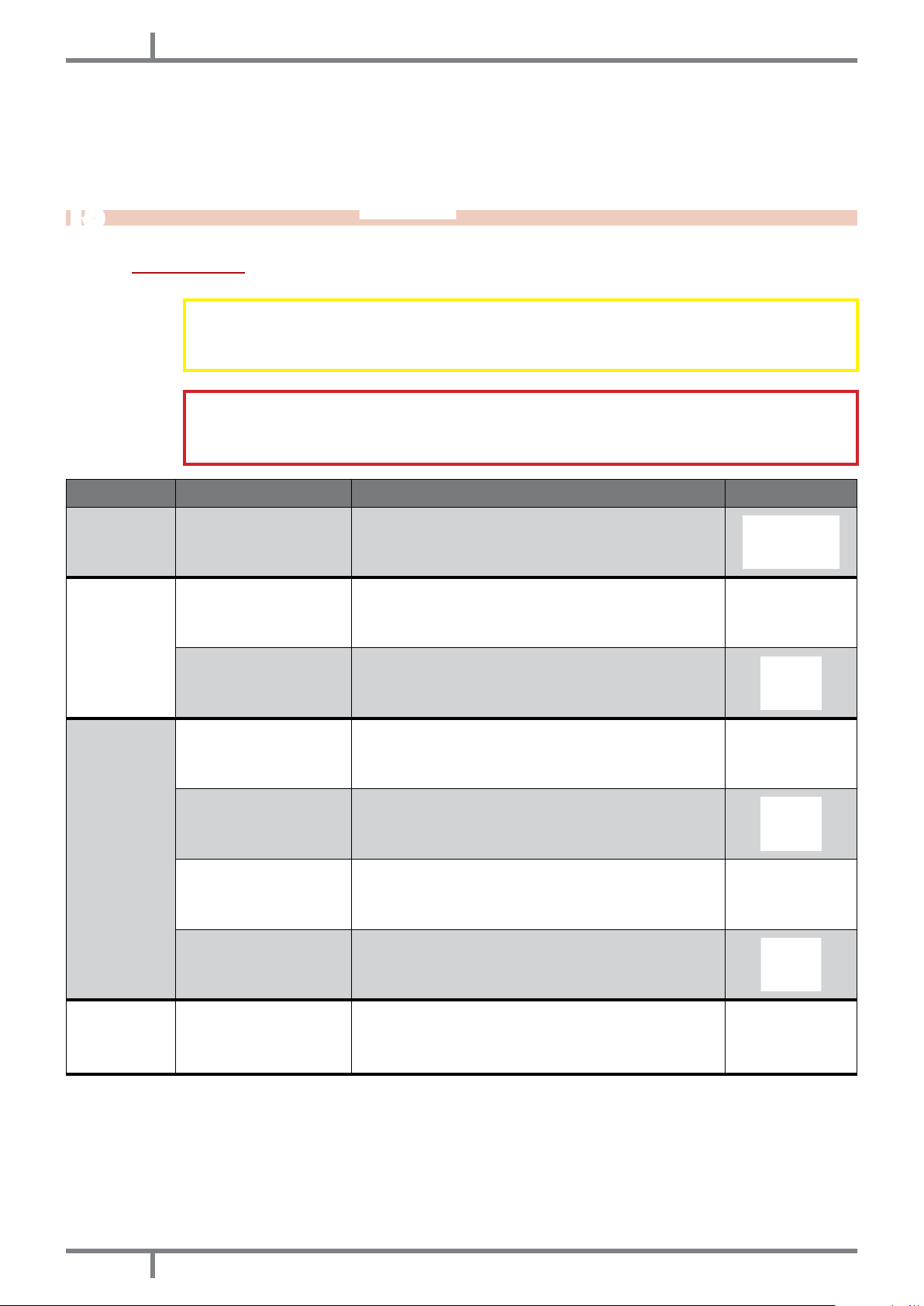
ALARM CAUSE SOLUTION INTERVENTION
AL 1 - BLACK
OUT
AL 2 - EXHAUST
PROBE
Black out during ignition
step
Disconnected fume
probe
Faulty fume temperature
probe
Clean the re pot and start the stove up again.
Have the stove checked.
Replace the fume probe.
AL 3 - HOT
EXHAUST
AL 4 - FAN
FAILURE
Faulty fume probe Replace the fume probe.
Faulty mother board Replace the mother board.
The ambient exchanger
fan does not work
Pellet loading value too
high "stage 5"
Fume extractor out of
order
Replace the ambient fan.
Adjust pellet loading
The pellet can burn also thank to chimney ue depression
without the aid of the extractor. Have the fume extractor
immediately replaced. It can be harmful to health to run
the stove without extractor.
32
EOLO - COMFORT 80
Page 33
EN
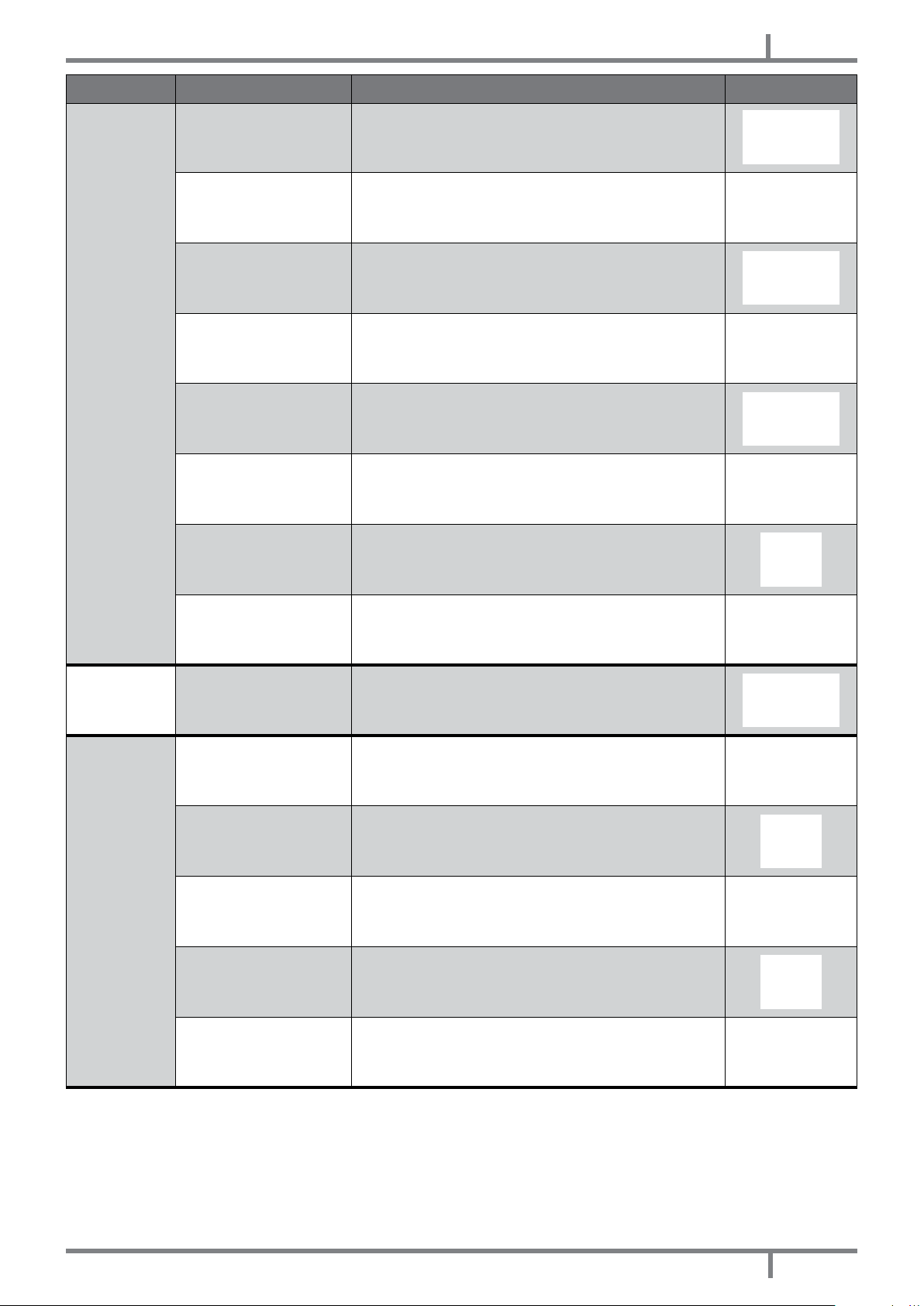
ALARM CAUSE SOLUTION INTERVENTION
Empty hopper Full the hopper.
AL 5 - NO
IGNITION
The burning pot has not
been cleaned
It has not reached the
ignition threshold to the
probe
Faulty ignition plug Replace the igniter resistance.
Too severe external
temperature
Humid pellet Assure you that the pellets are stored in a dry place.
Blocked thermal probe Replace the thermal probe.
Faulty mother board Replace the mother board.
Clean the burning pot.
Clean the burning pot and start the stove up again.
(If the problem persists please contact an Authorized
Technician).
Start the stove up again,
AL 6 - NO
PELLET
AL 7 - THERMAL
SAFETY
Empty hopper Fill the hopper.
Boiler overtemperature
The ambient exchanger
fan does not work
Temporary blackout
Faulty manual reset
thermostat
Faulty mother board Replace the mother board.
Let the stove cooling. (If the problem persists please
contact an Authorized Technician).
Replace the ambient fan.
The lack of tension during running implies boiler
overheating and manuel reset thermostat intervention.
Leave it cooling, reset and start the stove up again.
Replace the manual reset thermostat.
EOLO - COMFORT 80
33
Page 34
EN
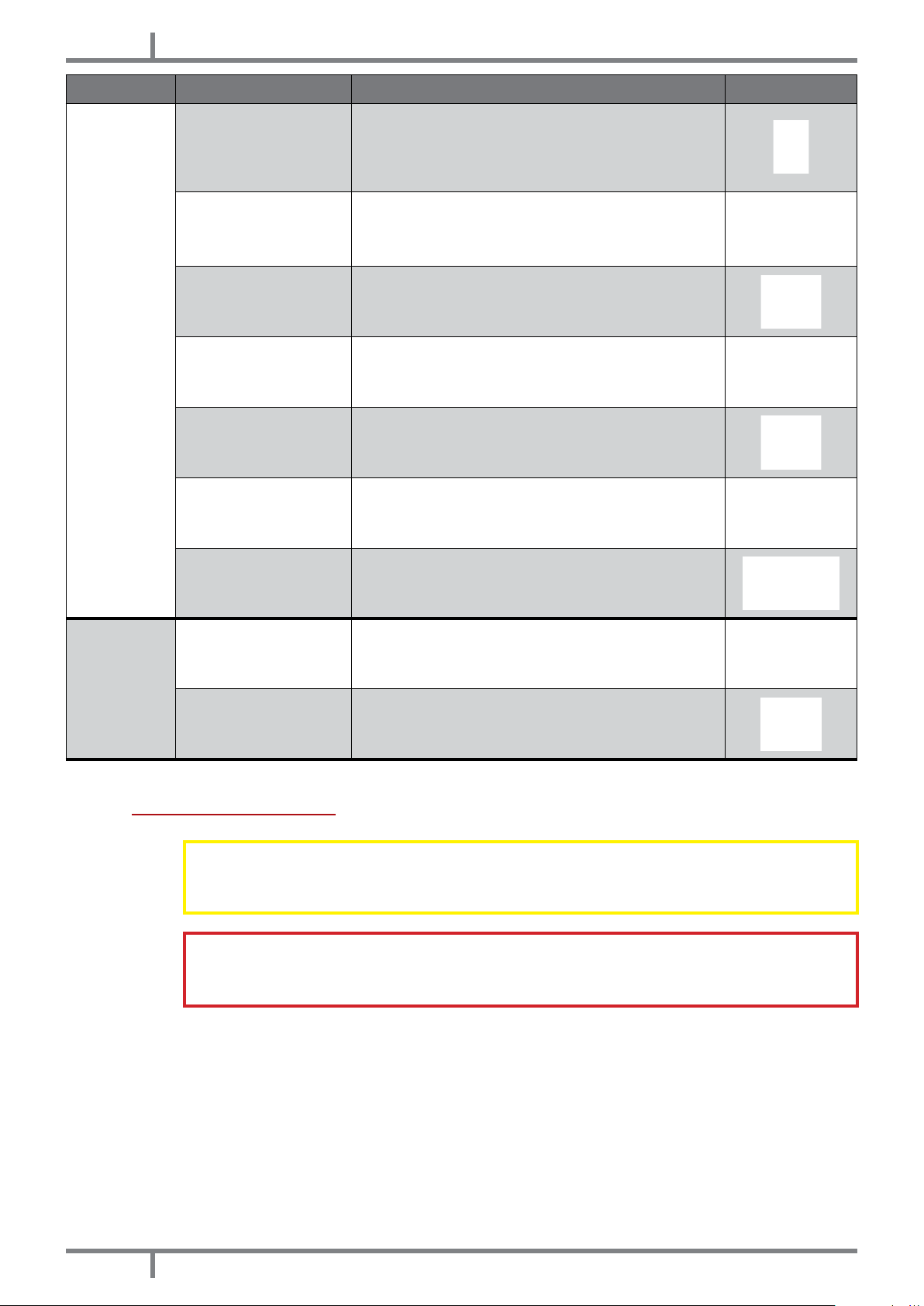
ALARM CAUSE SOLUTION INTERVENTION
The exhaust chimney is partially or tatally obstructed.
Obstructed exhaust
Faulty exhaust fan
Please contact a Specialized Stove-repairer who checks
the stove exhaust up to the chimney pot. Please have it
immediately cleaned. It can be harmful to health to run
the stove with the obstructed chimney.
The pellets can burn also thank to chimney ue depression
without the aid of the exhaust fan. Have the exhaust fan
immediately replaced. It can be harmful to health to run
the stove without exhaust fan.
AL 8 - FAILURE
DEPRESS
AL 9 - DOOR
OPEN
Obstructed outlet
connector
Faulty pressostat Clean the pressostat.
Faulty mother board Replace the mother board.
Extreme chimney lenght
Adverse weather
conditions
The re door is not
correctly closed
Fire door microswitch
faulty or out of order
Clean the outlet connector.
Contact a Specialized Stove-repairer and check that the
exhaust chimney is in accordance with the regulations:
see CHIMNEY FLUE page 6.
In case of strong wind there can be a negative pressure
to the chimney. Check it and start the stove up again.
Close the re door correctly and check if the gaskets
are damaged. (In this case have it replaced by an
Authorized Technician).
Replace the re door microswitch.
15.2 PROBLEM SOLVING
Before of every testing and/or intervention of the Authorized Technician, the Autorized
Technician personally has the duty to verify that the parameters of the electronic board
meet those of the reference table you own.
In case of doubts regarding the running of the stove please contact ONLY the Autorized
Technician in order to avoid irreparable damages!
34
EOLO - COMFORT 80
Page 35
EN
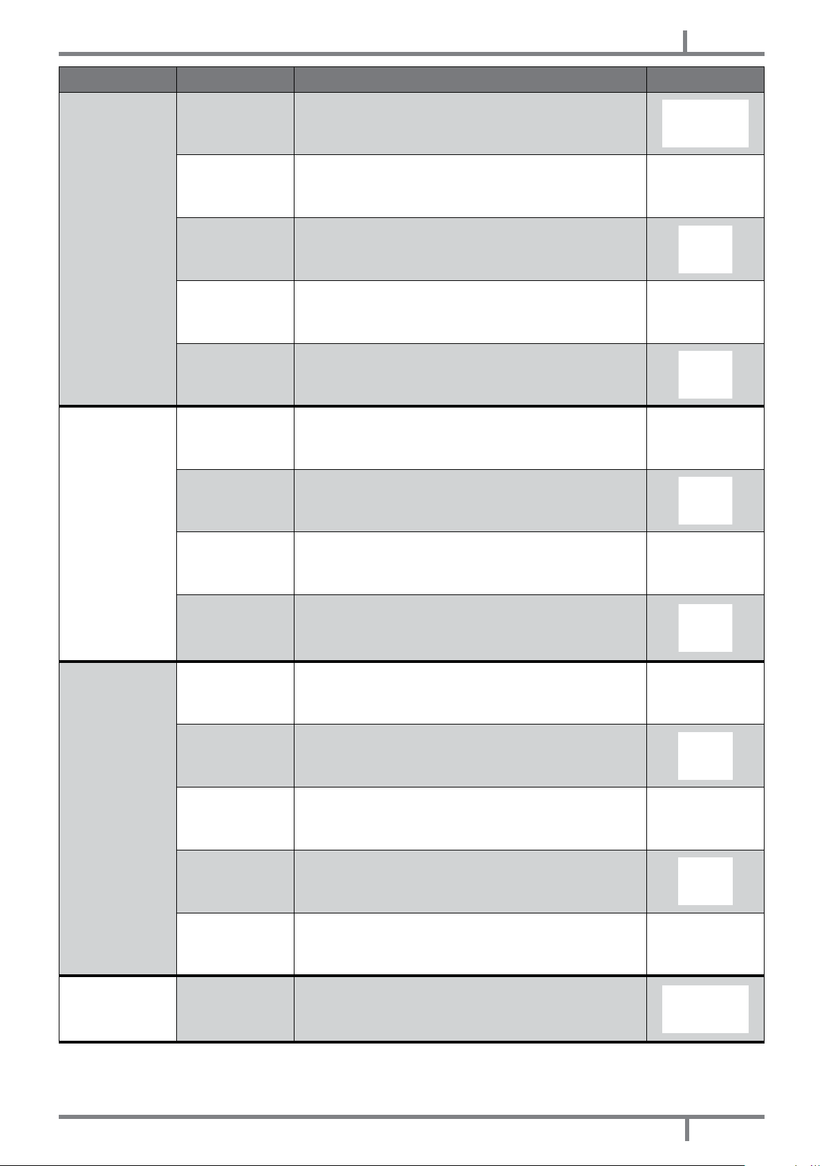
PROBLEM CAUSE SOLUTION INTERVENTION
Control display
does not ignite
Pellet does
not reach the
combustion
chamber
Stove without
power supply
Burned board
protection fuse
Faulty control
display
Faulty at cable Replace tha at cable.
Faulty mother
board
Empty hopper Fill the hopper.
Auger blocked by
a foreign object
(for example nails)
Auger
motorreducer out
of order
Check if the plug is put in the socket.
Replace the board protection fuse (4A-250V).
Replace the control display.
Replace the mother board.
Clean the auger.
Replace the motorreducer.
Fire extinguishes
and stove stalls
Running stove
and display
showing "FIRE POT
CLEANING"
Check on the
display if there is
an active alarm
"ACTIVE ALARM"
Empty hopper Fill the hopper.
Auger blocked by
a foreign object
(for example nails)
Poor quality pellet Try with other pellet types.
Pellet loading
value too law
"phase 1"
Check if there is
an active alarm
"ACTIVE ALARM"
Automatic
burning pot
cleaning
Have the stove overhauled.
Clean the auger.
Adjust pellet load.
Have the stove overhauled.
At idling stove and at maximum fume suction NO PROBLEM!
EOLO - COMFORT 80
35
Page 36

EN
PROBLEM CAUSE SOLUTION INTERVENTION
Flames are weak
and orange,
pellet does not
burn properly and
the glass blackens
Heat exchanger
fan keeps turning
even when the
stove has cooled
Ash nearby the
stove
Insufcient
combustion air
Obstructed
exhaust
Obstructed stove Clean the stove inner.
Exhaust fan out of
order
Faulty fume
temperature
probe
Faulty mother
board
Faulty or broken
door gaskets
Fume pipes not
sealed
Check the following inscription: probable obstructions
for combustion air inlet from the stove back or bottom;
obstructed holes of the burning pot grid and/or burning pot
with too ash. Have the fun blades and its screw cleaned.
The exhaust chimney is partly or fully obstructed. Contact
an expert stove-repairer to check the exhaust up to the
chimney pot. Please clean it immediately.
Pellet can burn also thank to chimney ue depression without
exhaust fan. Have the exhaust fan replaced immediately.
It can be harmful to health to run the stove without fume
exhaust fan.
Replace the fume probe.
Replace the mother board.
Replace the gaskets.
Contact an Autorized Stove-repairer who will seal the
gaskets with silicone at high temperature and/or will replace
the pipes with others in compliance with current regulations.
A not sealed fume outlet can cause damages to health.
Stove running and
display showing
"WORK MODULATI"
Stove running and
display showing
"HOT FUME"
16
TECHNICAL DATAS
Room
temperature
reached
Fume outlet limit
temperature
reached
Stove idling. NO PROBLEM!
Stove idling. NO PROBLEM!
16.1 REPAIR INFORMATION
Now we give some instructions for the Authorized Technician to take into consideration to have access to stove
mechanical components.
36
Fig. 49 - Retainers Fig. 50 - Insert extraction
EOLO - COMFORT 80
Page 37

EN
• Keeping pressed the yellow hooks downwards (see Fig. 49 page 36) extract the insert rolling it on its rails
(see Fig. 50 page 36).
Fig. 51 - Unnscrew casing screws Fig. 52 - Casing removal
• Unscrew the protection casing (see Fig. 51 page 37) and pull out the casing upwards (see Fig. 52 page
37).
Fig. 53 - Fan blocking screws Fig. 54 - Fan removal
• Unscrew the 2 fan blocking screws (see Fig. 53 page 37) and extract the fan following the arrow way (see
Fig. 54 page 37).
• After the preceeding operations it is possible to have access to siliconic pressostat tube, motor reducer and
ignition plug.
• For replacement and/or loading auger cleaning it is necessary to unscrew the three bolts of the motor
reducer and extract it, then unscrew the two screws which nd under the auger motor reducer and at the
end unscrew also the two inner auger bolts.
Fig. 55 - Fuse removal into the electric socket Fig. 56 - Fuse replacement
• For electric socket fuse replacement which stands under the insert, push with the aid of a screwdriver into the
shutter (see Fig. 55 page 37) and extract the shutter and the fuse to replace (see Fig. 56 page 37).
EOLO - COMFORT 80
37
Page 38

EN
16.2 FEATURES
DESCRIPTION EOLO COMFORT 80
WIDTH 79,6 cm 79,6 cm
DEPTH 60,1 cm 60,1 cm
HEIGHT 55,5 cm 55,5 cm
WEIGHT with PEDESTAL 144 kg 144 kg
INTRODUCED THERMIC POWER (Min/Max) 5,1 - 8,9 kW 5,1 - 8,9 kW
NOMINAL THERMIC POWER (Min/Max) 4,6 - 8 kW 4,6 - 8 kW
EFICIENCY (Min/Max) 87,5 - 88 % 87,5 - 88 %
FUME TEMPERATURE (Min/Max) 109 - 157°C 109 - 157°C
FUME MAXIMUM LOADING CAPACITY (Min/Max) 6,8 - 7,6 g/s 6,8 - 7,6 g/s
CO EMISSIONS (13% O
CO EMISSIONS
2
Medium CO CONTENTS at 13% O
Medium POWDER CONTENTS at 13% O
) (Min/Max) 0,042 - 0,011 % 0,042 - 0,011 %
2
(Min/Max) 5,4 - 9,1 % 5,4 - 9,1 %
(Min/Max) 530 - 139 mg/Nm3 530 - 139 mg/Nm3
2
(Max) 20 mg/Nm
2
3
20 mg/Nm
3
CHIMNEY DEPRESSION (Max) 12 Pa 12 Pa
MINIMUM SAFETY DISTANCE from ammable materials 20 cm 20 cm
ON SHARED CHIMNEY FLUE NO NO
FUME OUTLET DIAMETER Ø80 mm Ø80 mm
COMBUSTIBLE Pellet Ø6-7 mm Pellet Ø6-7 mm
PELLETS HEATING VALUE 5 kWh/Kg 5 kWh/Kg
PELLETS HUMIDITY ≤ 10% ≤ 10%
HEATING VOLUME 18/20°C Coeff. 0,045 kW (Min/Max) 110 -192 m
3
110 -192 m
3
HOURLY CONSUMPTION (Min/Max) 1,1 - 2,1 kg/h 1,1 - 2,1 kg/h
HOPPER CAPACITY 8 kg 8 kg
HOPPER CAPACITY + FILL OPENING (Min) 12 kg 12 kg
RANGE (Min/Max) 7,3 - 3,8 h 7,3 - 3,8 h
SUPPLY 230V - 50Hz 230V - 50Hz
POWER INPUT (Max) 340 W 340 W
INGNITER RESISTANCE POWER INPUT 300 W 300 W
MINIMUM EXTERNAL AIR INLET (last effective area) 80 cm
2
80 cm
STOVE WITH SEALED CHAMBER NO NO
EXTERNAL AIR INLET FOR SEALED CHAMBER - -
38
EOLO - COMFORT 80
2
Page 39

NL
Overzicht
1 IN DE HANDLEIDING GEBRUIKTE SYMBOLEN .... 40
2 BESTE KLANT ....................................................... 40
3 WAARSCHUWINGEN .......................................... 40
4 VEILIGHEIDSVOORSCHRIFTEN .......................... 41
5 GARANTIEVOORWAARDEN ............................... 42
6 RESERVEONDERDELEN ....................................... 43
7 AANWIJZINGEN VOOR EEN CORRECTE
VERWIJDERING VAN HET PRODUCT ......................... 43
8 VERPAKKING EN VERPLAATSING ...................... 43
8.1 VERPAKKING ..................................................43
8.2 VERPLAATSING VAN DE KACHEL .................. 44
9 ROOKKANAAL ................................................. 44
9.1 INLEIDING .......................................................44
9.2 ROOKKANAAL ................................................44
9.3 TECHNISCHE KENMERKEN .............................45
9.4 HOOGTE-ONDERDRUK .................................. 46
9.5 ONDERHOUD .................................................46
9.6 SCHOORSTEENPOT ........................................46
9.7 ONDERDELEN VAN DE SCHOORSTEEN ........ 46
9.8 BUITENLUCHTINLAAT ......................................47
9.9 AANSLUITING OP HET ROOKKANAAL...........47
9.10
VOORBEELDEN VAN CORRECTE INSTALLATIE
10 BRANDSTOF ........................................................ 50
10.1 BRANDSTOF ...................................................50
11 INSTALLATIE ........................................................ 50
11.1 INLEIDING ......................................................50
11.2 RUIMTEBESLAG ..............................................51
11.3 ALGEMENE INSTALLATIE ................................52
11.4
VERWIJDERING VAN HET INBOUWELEMENT
11.5 PLAATSING VAN HET INBOUWELEMENT ...... 54
11.6 INSTALLATIE MET EXTERNE BEKLEDING ......... 55
11.7 INSTALLATIE IN EEN BESTAANDE HAARD ..... 57
11.8 ELEKTRISCHE AANSLUITING ..........................58
11.9 AANSLUITING EXTERNE THERMOSTAAT ....... 59
12 GEBRUIK .............................................................. 59
12.1 INLEIDING .....................................................59
12.2 BEDIENINGSPANEEL ...................................... 59
12.3 GEBRUIKERSMENU ......................................... 60
12.4 STARTEN .........................................................61
12.5 INSTELLING KACHEL .................................... 61
12.6 GEEN ONTSTEKING ........................................62
12.7 GEEN ENERGIE ..............................................62
12.8 SET TEMPERATUUR .........................................62
12.9 TEMPERATUUR ROOKGASSEN ...................... 62
12.10 UITSCHAKELING ...........................................62
12.11 INSTELLINGEN KLOK ..................................... 62
12.12 DAGPROGRAMMERING ............................. 62
12.13 WEEKENDPROGRAMMERING ..................... 63
12.14 WEEKPROGRAMMERING ............................ 63
12.15 PELLETS BIJVULLEN ....................................... 63
12.16 SENSOR PELLETS ........................................... 64
12.17 AFSTANDSBEDIENING .................................. 64
... 48
.... 53
13 VEILIGHEIDSVOORZIENINGEN ......................... 64
13.1 INLEIDING ......................................................64
13.2 ALARM "BLACK OUT" ....................................64
13.3 ALARM "FUME PROBE" .................................. 65
13.4 ALARM "HOT FUME" ......................................65
13.5 ALARM "FAN FAILURE" ..................................65
13.6 ALARM "FAILED IGNITION" ............................ 65
13.7 ALARM "NO PELLET" ......................................65
13.8 ALARM "THERMAL SAFETY" ...........................65
13.9 ALARM "FAILURE DEPRESS" ........................... 65
13.10 ALARM "OPEN DOOR" ................................ 65
14 ONDERHOUD ...................................................... 66
14.1 INLEIDING ......................................................66
14.2 REINIGING VUURPOT EN ASLADE ................ 66
14.3
REINIGING VAN DE VERBRANDINGSKAMER ....
14.4 REINIGING VOORRAADBAK EN
TRANSPORTSCHROEF ............................................ 67
14.5 REINIGING ROOKGASSENKAMER ................ 67
14.6 REINIGING ROOKLEIDING ............................ 68
14.7
REINIGING VAN DE ROOKGASSENAFZUIGER....
14.8 REINIGING ROOKGASSENDOORGANG ..... 69
14.9 JAARLIJKSE REINIGING VAN DE
ROOKGASSENLEIDINGEN .....................................69
14.10 ALGEMENE REINIGING ................................ 69
14.11 REINIGING VAN GELAKTE METALEN
ONDERDELEN .........................................................69
14.12 VERVANGING VAN DE PAKKINGEN .......... 69
14.13 REINIGING VAN HET GLAS .......................... 69
14.14 REINIGING VAN HET GLAS .......................... 70
15 IN GEVAL VAN ONGEMAKKEN ......................... 70
15.1 ALARMEN .......................................................70
15.2 OPLOSSING VAN DE PROBLEMEN ............... 73
16 TECHNISCHE GEGEVENS ................................. 75
16.1 INFORMATIE VOOR DE REPARATIE .............. 75
16.2 KENMERKEN ................................................... 77
67
68
EOLO - COMFORT 80
39
Page 40

NL
1
• De iconen met de mannetjes geven aan tot wie het in de paragraaf behandelde onderwerp gericht is
• De AANDACHTS-symbolen duiden op een belangrijke opmerking.
IN DE HANDLEIDING GEBRUIKTE SYMBOLEN
(gebruiker en/of geautoriseerde technicus en/of kachel- en schoorsteenspecialist).
GEBRUIKER
GEAUTORISEERDE TECHNICUS
(moet UITSLUITEND opgevat worden als: of de fabrikant van de kachel,
of de geautoriseerde technicus van de technische assistentiedienst die
door fabrikant van de kachel erkend is)
GESPECIALISEERDE INSTALLATEUR
LET OP:
LEES DE OPMERKING MET AANDACHT
LET OP:
MOGELIJKHEID VAN GEVAAR OF ONHERSTELBARE SCHADE
2
• onze producten zijn ontworpen en geconstrueerd met inachtneming van de normen EN13240 voor
• Lees de instructies die in deze handleiding staan met aandacht om de beste prestaties te verkrijgen.
• Deze handleiding met instructies maakt integraal deel uit van het product: controleer of de handleiding zich
• Volgens de Verordening (EU) nr. 305/2011, de "Prestatieverklaring" is online beschikbaar aan de internetsite
3
• Alle afbeeldingen die in de handleiding staan, zijn van louter verhelderende en indicatieve aard en kunnen
• Het apparaat waarnaar verwezen wordt, is het apparaat dat u gekocht heeft.
• In geval van twijfel, als u iets niet begrijpt, of wanneer zich problemen voordoen die niet door deze handleiding
BESTE KLANT
houtkachels, EN 14785 voor pelletkachels, EN 13229 voor haarden, EN12815 voor houtgestookte fornuizen,
C.P.R. 305/2011 voor te construeren producten, EG-verordening1935/2004 voor materialen en voorwerpen
die in aanraking met levensmiddelen komen, Richtlijn 2006/95/EEG voor laagspanning, Richtlijn 2004/108/EG
voor elektromagnetische compatibiliteit.
altijd bij het apparaat bevindt, ook als dit van eigenaar verandert. Bent u de handleiding kwijtgeraakt, vraag
dan een kopie aan bij de technische assistentiedienst bij u in de buurt.
In Italië wordt voor de installatie van systemen met een biomassa van minder dan 35 kW
naar Ministerieel Besluit D.M. 37/08 verwezen en iedere gekwaliceerde installateur die aan
de daarvoor gestelde eisen voldoet moet de conformiteitsverklaring van het geïnstalleerde
systeem afgeven (met "systeem" wordt bedoeld: kachel + schoorsteen + luchtinlaat).
www.cadelsrl.com / www.free-point.it.
WAARSCHUWINGEN
dus enigszins afwijken van het apparaat dat u in bezit heeft.
behandeld worden, verzoeken wij u zo snel mogelijk contact op te nemen met uw distributeur of installateur.
40
EOLO - COMFORT 80
Page 41

NL
4
VEILIGHEIDSVOORSCHRIFTEN
• De installatie, de elektrische aansluiting, de controle van de werking en het onderhoud
mogen uitsluitend door gekwaliceerd en bevoegd personeel uitgevoerd worden.
• Elektrische onderdelen onder spanning: U moet het product van de 230V voeding
loskoppelen vooraleer onderhoudswerkzaamheden uit te voeren. U mag het product
pas voeden nadat de assemblage is voltooid.
• Het buitengewone onderhoud mag uitsluitend uitgevoerd worden door
gekwaliceerd en geautoriseerd personeel.
• Alle plaatselijke reglementen, met inbegrip van de reglementen die naar nationale,
Europese normen verwijzen, moeten op het moment van installatie van het apparaat
in acht genomen worden.
• De fabrikant stelt zich op generlei wijze aansprakelijk voor een installatie die niet
conform de van kracht zijnde wetten is, voor een onjuiste luchtverversing in de
vertrekken, voor een elektische aansluiting die niet conform de voorschriften is en
voor een oneigenlijk gebruik van het apparaat.
• Het is verboden de kachel te installeren in slaapkamers, badkamers en
douches, in ruimtes die als magazijn van verbrandingsmateriaal dienst doen en in
eenkamerwoningen.
• Het is toegestaan de kachel in eenkamerwoningen te installeren als de kachel
een hermetisch gesloten kamer heeft.
• De kachel mag in geen geval geïnstalleerd worden in ruimtes die hem blootstellen
aan contact met water, en helemaal niet aan waterspetters, omdat dit het risico op
brandwonden en korsluiting kan veroorzaken.
• Controleer of de vloer een adequate capaciteit heeft om de last te dragen. Als
de bestaande constructie niet aan deze eis voldoet, moeten passende maatregelen
getroffen worden (bijvoorbeeld een plaat voor de verdeling van het gewicht).
• Voor de veiligheidsvoorschriften op het gebied van de brandpreventie moeten
de afstanden ten opzichte van ontvlambare of hittegevoelige objecten in acht
genomen worden (banken, meubels, houten bekleding, enz....).
• Bij zeer ontvlambare objecten (gordijnen, vloerbedekking, enz...) moeten al deze
afstanden bijkomend met 1 meter verlengd worden.
• De elektrische kabel mag nooit in aanraking met de rookgassenafvoerpijp komen
en ook niet met ongeacht welk ander deel van de kachel.
• Voordat ongeacht welke handeling uitgevoerd wordt, moet de gebruiker of een
ieder die met het product gaat werken de volledige inhoud van deze handleiding
voor installatie en gebruik gelezen en begrepen hebben. Fouten of slechte instellingen
kunnen gevaarlijke situaties en/of een onregelmatige werking veroorzaken.
• Het type brandstof dat gebruikt moet worden is enkel en alleen pellets.
• Gebruik het apparaat niet als afvalverbrander.
• Laat geen wasgoed op het product drogen. Eventuele droogrekken of dergelijke
moeten op voldoende afstand van het product geplaatst worden. Brandgevaar.
• Het is verboden om het product in werking te stellen als de deur open staat of het
glas stuk is.
• Het is verboden niet geautoriseerde wijzigingen op het apparaat aan te brengen.
• Gebruik tijdens de inschakeling geen ontvlambare vloeistoffen (alcohol, benzine,
petroleum, enz...).
• Na een mislukte ontsteking moeten de opeengehoopte pellets uit de vuurpot
gehaald worden alvorens de kachel opnieuw te starten.
• De voorraadbak van de pellets moet altijd met het deksel afgesloten zijn.
• Alvorens ongeacht welke ingreep uit te voeren, dient men het vuur in de
verbrandingskamer volledig uit te laten gaan, tot de kamer volledig koel is, en moet
de stekker altijd uit het stopcontact getrokken worden.
• Het toestel mag gebruikt worden door kinderen vanaf 8 jaar en door mensen met
beperkte lichamelijke, zintuiglijke of mentale capaciteiten, of zonder ervaring of de
nodige kennis, mits zij onder toezicht staan of nadat ze instructies hebben gekregen
EOLO - COMFORT 80
41
Page 42

NL
betreffende het veilige gebruik van het toestel en het begrip van de gevaren die
inherent aan het toestel zijn. Kinderen mogen niet met het toestel spelen. De reiniging
en het onderhoud dat door de gebruiker moet worden uitgevoerd, mag niet door
kinderen zonder toezicht worden uitgevoerd.
• De verpakkingen zijn geen speelgoed, ze kunnen het risico op verstikking of wurging
en andere gevaren voor de gezondheid veroorzaken! Mensen (met inbegrip van
kinderen) met verminderde geestelijke of motorische bekwaamheden, of zonder
ervaring en kennis, dienen ver van de verpakkingen gehouden te worden. De kachel
is geen speelgoed.
• Kinderen moeten constant onder toezicht staan om er zeker van te zijn dat ze niet
met het apparaat spelen.
• Tijdens de werking kan de kachel hoge temperaturen bereiken: houd kinderen en
dieren op afstand en gebruik geschikte, vuurvaste, persoonlijke beschermingsmiddelen,
zoals hittebestendige handschoenen.
• Als de transportschroef door een onbekend voorwerp geblokkeerd wordt (zoals
bijvoorbeeld spijkers), moet hij gereinigd worden. Verwijder de handenbescherming
niet en raak de transportschroef niet aan). Neem contact met de technische
assistentiedienst.
• De handenbescherming mag uitsluitend door een geautoriseerde technicus
weggenomen worden.
• Het rookkanaal moet altijd schoon zijn omdat de aanslag van roet of onverbrande
olie de doorsnede verkleint en de trek blokkeert. In grote hoeveelheden kan deze
aanslag in brand raken.
• Als de pellets van slechte kwaliteit zijn (ze bevatten lijm, olie, lak, residu van
plastic of zijn kruimig), kan tijdens de werking een residu langs de pelletafvoerleiding
gevormd worden. Is de kachel eenmaal uitgeschakeld dan kan dit residu hele kleine
gloeiende kooltjes vormen die opwaarts langs de leiding de pellets in de voorraadbak
kunnen bereiken, deze kunnen doen verkolen en zo een dichte, schadelijke rook in
het vertrek kunnen veroorzaken. Houd de voorraadbak altijd afgesloten met diens
deksel. Mocht de buis vuil blijken te zijn, reinig deze dan.
• Mocht het nodig zijn het vuur te moeten doven dat zich buiten de kachel of het
rookkanaal verspreidt, gebruik dan een blusser of bel de brandweer. Gebruik nooit
water om het vuur in de vuurpot te doven.
5
Het bedrijf geeft garantie op het product, met uitzondering van de elementen onderhevig aan normale slijtage
zoals hierna vermeld, gedurende 2 (twee) jaar vanaf de datum van aankoop, wat wordt aangetoond door:
• een bewijsdocument (factuur en/of scaal bewijs) dat de naam van de verkoper en de datum vermeldt
• de verzending van het garantiecerticaat, ingevuld binnen 8 dagen na de aankoop.
Opdat de garantie verder zou geldig worden en effectief zijn, mag de installatie volgens de regels van de kunst
en de inwerkingstelling van het toestel uitsluitend door gekwaliceerd personeel worden uitgevoerd, dat in de
voorziene gevallen aan de gebruiker een gelijkvormigheidsattest van de installatie en verklaring van goede
werking van het toestel moet overhandigen.
Wij raden aan om de werkingstest van het toestel uit te voeren vooraleer de voltooiing met de desbetreffende
afwerkingen (bekledingen, kleurafwerking van de wanden, enz.) te doen.
Installaties die niet overeenkomen met de geldende normen doen de garantie van het product vervallen,
evenals oneigenlijk gebruik en het niet uitvoeren van het onderhoud zoals door de fabrikant voorzien.
De garantie is van kracht op voorwaarde dat de aanwijzingen en waarschuwingen worden nageleefd in de
handleiding voor gebruik en onderhoud dat bij het toestel zit, zodat een zo correct mogelijk gebruik mogelijk is.
De vervanging van het hele toestel of de reparatie van een van zijn onderdelen zorgen niet voor verlenging van
de garantie, die ongewijzigd blijft.
Met garantie wordt de gratis vervanging of reparatie bedoeld van delen die als defect worden erkend als
gevolg van fabricatiefouten.
Om zich op de garantie te kunnen beroepen wanneer er zich een defect voordoet, moet de eigenaar het
garantiecerticaat bewaren en dit samen met het aankoopbewijs aan de technische dienst voor assistentie
voorleggen.
Alle slechte werkingen en/of schade aan het toestel die aan de volgende oorzaken te wijten zijn, zijn van deze
garantie uitgesloten:
• Schade veroorzaakt door transport en/of verplaatsing.
• Alle delen die defect blijken door verwaarlozing of onachtzaamheid tijdens het gebruik, door foutief
GARANTIEVOORWAARDEN
waarop de verkoop plaatsvond;
onderhoud, door een installatie die niet conform is met wat door de fabrikant is aangegeven (raadpleeg
42
EOLO - COMFORT 80
Page 43

NL
altijd de handleiding voor installatie en gebruik die bij het toestel zit).
• Foutieve dimensionering in verhouding tot het gebruik of defecten tijdens de installatie of het niet toepassen
van de nodige maatregelen om een uitvoering volgens de regels van de kunst te verzekeren.
• Onjuiste oververhitting van het toestel, namelijk door gebruik van brandstoffen die niet conform zijn met het
type en met de hoeveelheden aangegeven in de meegeleverde instructies.
• Andere schade veroorzaakt door foutieve interventies van de gebruiker wanneer die probeert om het
oorspronkelijke defect zelf op te lossen.
• Verergering van de schade veroorzaakt door het toestel verder te gebruiken nadat het defect zich voordeed.
• Eventuele corrosie, aanslag of breuken veroorzaakt door zwerfstroom, condens, agressiviteit of zuurheid
van het water, onjuist uitgevoerde aanslagwerende behandelingen, watertekort, bezinksel van modder of
kalkaanslag.
• Inefciëntie van de schoorstenen, rookgaskanalen of delen van de installatie waarvan het toestel afhangt.
• Schade toegebracht door het openbreken van het toestel, weersinvloeden, natuurrampen, vandalisme,
elektrische schokken, brand, defecten aan de elektrische en/of hydraulische installatie.
• Wanneer de jaarlijkse reiniging van de kachel door een erkende technicus of door gekwaliceerd personeel
niet wordt uitgevoerd, verliest u de garantie.
Bovendien is het volgende van deze garantie uitgesloten:
• Onderdelen onderhevig aan normale slijtage, zoals pakkingen, ruiten, bekledingen en roosters in gietijzer,
gelakten verchroomde of vergulde onderdelen, de handgrepen en elektrische kabels, lampen, verlichte
controlelampjes, draaiknoppen en alle delen van de vuurhaard die weggenomen kunnen worden.
• De kleurwijzigingen van de gelakte delen en de delen van keramiek/serpentijn, alsook barstjes in de keramiek,
omdat dit natuurlijke kenmerken van het materiaal en van het gebruik van het product zijn.
• Metselwerk.
• Onderdelen van de installatie (indien aanwezig) die niet door de fabrikant zijn geleverd.
Eventuele technische interventies op het toestel om voornoemde defecten en daaruit voortvloeiende schade
weg te nemen, moeten bijgevolg met de technische dienst voor assistentie worden overeengekomen. Deze
dienst behoudt zich het recht voor om de betreffende opdracht al of niet te aanvaarden en de opdracht wordt
in ieder geval niet in garantie uitgevoerd, maar wel als technische assistentie geleverd onder eventuele speciek
overeengekomen voorwaarden en volgens de tarieven die van kracht zijn voor de uit te voeren werken.
Bovendien worden de kosten nodig om foutieve technische interventies uitgevoerd door de gebruiker te
corrigeren, om forceringen te herstellen of alle andere schadelijke factoren die niet te herleiden zijn tot
oorspronkelijke defecten, ten laste van de gebruiker zijn.
Met uitzondering van de beperkingen die door de wetten of reglementeringen worden opgelegd, blijft verder
iedere garantie uitgesloten voor atmosferische en akoestische vervuiling.
Het bedrijf kan niet aansprakelijk gesteld worden voor eventuele schade die, rechtstreeks of onrechtstreeks,
te wijten is aan personen, dieren of voorwerpen als gevolg van het niet respecteren van alle voorschriften
die aangeduid worden in deze handleiding, en vooral diegene betreffende de installatie, het gebruik en het
onderhoud van het toestel.
6
Voor iedere reparatie of jnafstelling die nodig mochten zijn, dient u zich te wenden tot de concessionaris die de
verkoop verricht heeft, of tot de technische assistentiedienst bij u in de buurt, onder vermelding van:
• Model van het apparaat
• Serienummer
• Type ongemak
Gebruik alleen originele reserveonderdelen die u altijd bij onze assistentiecentra vindt.
7
De afbraak en het verwijderen van het product is uitsluitend ten laste van en op verantwoordelijkheid van de
eigenaar, die moet handelen in naleving van de geldende wetten in zijn land inzake veiligheid en milieubehoud.
Aan het einde van de nuttige levensduur mag het product niet samen met het gewone huishoudafval worden
verwerkt.
Het moet naar een speciaal centrum voor gescheiden afvalinzameling van de gemeente worden gebracht, of
naar een verkooppunt dat deze service verschaft.
Het gedifferentieerd verwijderen van het product voorkomt mogelijke negatieve gevolgen voor het milieu en
de gezondheid die door een ongeschikte verwijdering ontstaan en zorgt ervoor dat de materialen waaruit
het apparaat bestaat teruggewonnen kunnen worden om een aanmerkelijke besparing van energie en
grondstoffen te verkrijgen.
RESERVEONDERDELEN
AANWIJZINGEN VOOR EEN CORRECTE VERWIJDERING VAN HET PRODUCT
8
VERPAKKING EN VERPLAATSING
8.1 VERPAKKING
• De verpakking bestaat uit een recyclebare kartonnen doos volgens de RESY-normen, recyclebare inzetstukken
van geëxpandeerd EPS en houten pallets.
• Alle verpakkingsmaterialen kunnen voor een gelijkaardig gebruik hergebruikt worden of eventueel als
stadsafval, met inachtneming van de van kracht zijnde normen, weggegooid worden.
EOLO - COMFORT 80
43
Page 44

NL
• Controleer de intacte staat van het product na de verpakking te hebben weggenomen.
8.2 VERPLAATSING VAN DE KACHEL
Zowel voor de verpakte als voor de uitgepakte kachel is het noodzakelijk de volgende instructies voor de
verplaatsing en het transport van de kachel zelf in acht te nemen, vanaf het moment van aankoop tot het
bereiken van het punt van gebruik en voor iedere andere toekomstige verplaatsing:
• verplaats de kachel met geschikte werktuigen en let op de normen die van kracht zijn op het gebied van
de veiligheid;
• leg de kachel niet op één zijde en/of kantel hem niet maar houd hem verticaal of hoe dan ook overeenkomstig
de aanwijzingen van de fabrikant;
• als de kachel onderdelen van majolica, steen, glas, of hoe dan ook van bijzonder delicate materialen bevat,
verplaats het geheel dan zeer voorzichtig.
9
ROOKKANAAL
9.1 INLEIDING
Dit hoofdstuk Rookkanaal is opgesteld in samenwerking met Assocosma (www.assocosma.org) en is gebaseerd
op de Europese normen (EN 15287 - EN 13384 - EN 1856 - EN 1443 - UNI 10683:2012).
Het hoofdstuk verstrekt aanwijzingen over de goede en correcte totstandkoming van het rookkanaal maar
dient in geen geval als vervanging van de van kracht zijnde normen te gelden, die in het bezit van de fabrikant/
gekwaliceerde installateur moeten zijn.
Controleer bij de plaatselijke overheid of er beperkende normen zijn die betrekking hebben
op de inlaat van de verbrandingslucht, de rookafvoerinstallatie, het rookkanaal of de
schoorsteenpot.
De rma stelt zich op generlei wijze aansprakelijk voor de slechte werking van de kachel als die te wijten is aan
het gebruik van een rookkanaal met verkeerde afmetingen dat niet aan de van kracht zijnde normen voldoet.
9.2 ROOKKANAAL
Fig. 1 - Rookkanalen
LEGENDA Fig. 1 op pag. 44
1 Rookkanaal met geïsoleerde inox-buizen
2 Rookkanaal op bestaande schoorsteen
3 Inspectiedop
4 Inspectieluikje
5 ≥ 3,5 m.
• Het rookkanaal of de schoorsteen zijn zeer belangrijk voor de goede werking van een verwarmingsapparaat.
44
EOLO - COMFORT 80
Page 45

NL
• Het is van essentieel belang dat het rookkanaal volgens de regels van het vak geconstrueerd is en altijd
perfect efciënt gehouden wordt.
• Het rookkanaal moet enkelvoudig zijn (zie Fig. 1 op pag. 44 met geïsoleerde inox-buizen (1) of op een
bestaand rookkanaal (2).
• Beide oplossingen moeten een inspectiedop (3) en/of een inspectieluikje (4) bezitten.
9.3 TECHNISCHE KENMERKEN
Fig. 2 - Schuin dak
LEGENDA Fig. 2 op pag. 45
1 Hoogte boven de nok van het dak = 0,5 m
2 Helling dak ≥ 10°
3 90°
4 Gemeten afstand op 90° van het oppervlak van het dak = 1,3 m.
• Het rookkanaal moet rookdicht zijn.
• Het moet een verticaal verloop hebben, zonder knikken, en moet van materialen gemaakt zijn die
ondoordringbaar zijn voor rook en condens, die thermisch geïsoleerd zijn en geschikt zijn om door de tijd
heen bestand te zijn tegen normale mechanische belastingen.
Het rookkanaal moet extern geïsoleerd zijn ter vermijding van condensvorming en moet het
effect van koeling van de rookgassen verlagen.
• Het moet zich door middel van een luchtbuffer of isolatiemateriaal op afstand van brandbare of gemakkelijk
ontvlambare materialen bevinden. Controleer deze afstand bij de producent van de schoorsteen.
• De opening van de schoorsteen moet zich in dezelfde ruimte bevinden waarin het apparaat geïstalleerd is,
of op zijn minst in de aangrenzende ruimte. Onder de opening moet een opvangruimte voor vast materiaal
en condens aanwezig zijn, die via het metalen, hermetisch gesloten deurtje toegankelijk is.
• Extra afzuigsystemen mogen noch langs de schoorsteen noch op de schoorsteenpot geïnstalleerd zijn.
• De binnendoorsnede van het rookkanaal kan rond zijn (het best), of vierkant, waarbij de op elkaar aangesloten
zijden een minimumstraal van 20 mm hebben.
• De grootte van de doorsnede is:
• minimaal Ø100 mm (voor kachels tot 8,5 kw)
• minimaal Ø120 mm (voor kachels van 9 kW en hoger)
• Laat de efciëntie van het rookkanaal door een ervaren kachel- en schoorsteenspecialist nakijken en bedek
het rookkanaal zo nodig met materiaal dat aan de van kracht zijnde normen voldoet.
• De afvoer van de verbrandingsproducten moet plaatsvinden op het dak.
• Het rookkanaal moet het CE-plaatje bezitten volgens de norm EN 1443. Hieronder een voorbeeldplaatje:
EOLO - COMFORT 80
Fig. 3 - Voorbeeld van een plaatje
45
Page 46

NL
9.4 HOOGTE-ONDERDRUK
De onderdruk (trek) van een rookkanaal is ook afhankelijk van diens hoogte. Controleer de onderdruk met de
waarden die vermeld worden bij KENMERKEN op KENMERKEN op pag. 77. Minimum hoogte 3,5 meter.
9.5 ONDERHOUD
• De rookafvoerleidingen (rookleiding + rookkanaal + schoorsteenpot) moeten altijd door een ervaren
schoorsteenveger gereinigd, geveegd en gecontroleerd worden in overeenstemming met de plaatselijke
regelgeving, met aanduiding van de producent van de schoorsteen en met de richtlijnen van uw
verzekeringsmaatschappij.
• Pas in geval van twijfel altijd de strengste regels toe.
• Laat het rookkanaal en de schoorsteenpot minstens één keer per jaar door een ervaren schoorsteenveger
controleren en reinigen. De schoorsteenveger moet een schriftelijke verklaring afgeven waarin staat dat het
systeem veilig is.
• Het niet reinigen compromitteert de veiligheid.
9.6 SCHOORSTEENPOT
Fig. 4 - Windbestendige schoorsteenpotten
De schoorsteenpot heeft een belangrijke functie voor de goede werking van de verwarmingsapparatuur:
• Er wordt geadviseerd een windbestendige schoorsteenpot te gebruiken, zie Fig. 4 op pag. 46.
• De zone van de gaten voor de afvoer van de rookgassen moet twee keer zo groot zijn als de zone van het
rookkanaal en zo gevormd zijn dat de afvoer van de rook ook in geval van wind verzekerd wordt.
• Deze zone moet voorkomen dat regen, sneeuw en eventueel dieren de schoorsteen binnendringen.
• De hoogte waarop de rookgassen in de atmosfeer uitgestoten worden, moet buiten de zone van terugstroming
liggen. Deze terugstroming wordt veroorzaakt door de vorm van het dak of door obstakels die zich in de
nabijheid bevinden (zie Fig. 2 op pag. 45).
9.7 ONDERDELEN VAN DE SCHOORSTEEN
46
Fig. 5 - Onderdelen van de schoorsteen
EOLO - COMFORT 80
Page 47

LEGENDA Fig. 5 op pag. 46
9.8 BUITENLUCHTINLAAT
NL
1 Schoorsteenpot
2 Uitstroomweg
3 Rookkanaal
4 Thermische isolatie
5 Buitenmuur
6 Aansluiting van de schoorsteen
7 Rookleiding
8 Warmtegenerator
9 Inspectieluikje
10 T-aansluiting met inspectiedop
Fig. 6 - Directe luchttoevoer Fig. 7 - Indirecte luchttoevoer
LEGENDA Fig. 6 op pag. 47 - Fig. 7 op pag. 47
1 Te ventileren vertrek
2 Aangrenzend vertrek
3 Buitenluchtinlaat
4 Opening onder de deur voor toename
• Het is verplicht om voor buitenluchtrecirculatie te zorgen ten behoeve van een goed welzijn in het vertrek.
• De luchttoevoer tussen de buitenlucht en het vertrek kan zowel direct plaatsvinden, via een opening in de
buitenmuur van het vertrek (zie Fig. 6 op pag. 47), danwel indirect, via opname van de lucht uit vertrekken
die aan het te ventileren vertrek grenzen (zie Fig. 7 op pag. 47).
• Vertrekken als slaapkamers, berghokken, garages, magazijnen voor brandbaar materiaal mogen hiervoor
niet in aanmerking komen.
• De luchtinlaatopening moet in zijn totaal een minimum netto oppervlak van 80 cm2 hebben genoemd
oppervlak moet vergroot worden als er andere actieve generatoren in het vertrek aanwezig zijn (bijvoorbeeld:
een elektroventilator voor de extractie van verzadigde lucht, een keukenafzuigkap, andere kachels, enz,,,).
die het vertrek in onderdruk brengen.
• Het is noodzakelijk te laten nakijken - wanneer alle apparatuur ingeschakeld is - of de drukval tussen het vertrek
en de buitenlucht niet groter is dan 4,0 Pa: vergroot de opening van de luchtinlaat zo nodig (EN 13384).
• De luchtinlaat moet tot stand gebracht worden op een hoogte vlakbij de vloer, met een extern rooster dat
bescherming tegen vogels biedt, en op een wijze dat het door geen enkel object belemmerd wordt.
• De luchtinlaat is niet nodig in het geval van een hermetisch gesloten installatie.
9.9 AANSLUITING OP HET ROOKKANAAL
De pelletkachel werkt door de trek van rook die gestuwd wordt door een ventilator. Het is verplicht te controleren
of alle leidingen volgens de regels van het vak tot stand gekomen zijn, volgens de normen EN 1856-1, EN 1856-2
en UNI/TS 11278 inzake de keuze van de materialen. Het geheel moet in ieder geval gerealiseerd worden door
gespecialiseerde bedrijven of personeel volgens UNI 10683:2012.
• De aansluiting tussen het apparaat en het rookkanaal moet kort zijn om de trek te bevorderen en
condensvorming in de leidingen te voorkomen.
• Het rookkanaal moet groter of gelijk zijn aan de afvoerpijp (Ø 80 mm).
• Enkele modellen kachels hebben de afvoer aan de zijkant en/of de achterkant. Controleer of de ongebruikte
afvoer gesloten wordt met de bijgeleverde dop.
EOLO - COMFORT 80
47
Page 48

NL
TYPE SYSTEEM BUIS Ø80 mm BUIS Ø100 mm
Minimum verticale lengte 1,5 m. 2 m.
Maximum lengte (met 1 aansluiting) 6,5 m. 10 m.
Maximum lengte (met 3 aansluitingen) 4,5 m. 8 m.
Maximum aantal aansluitingen 3 3
Horizontale delen (minimum helling 3%) 2 m. 2 m.
Installatie op een hoogte van meer dan 1200 meter n.a.p. NEE Verplicht
• Gebruik specieke buizen van plaatstaal voor rookkanalen met Ø80 mm of Ø100 mm, afhankelijk van het
type systeem, met siliconen pakkingen.
• Het is verboden buigzame metalen buizen van vezelcement of aluminium te gebruiken.
• Om van richting te veranderen is het verplicht altijd van aansluitingen gebruik te maken (met hoek > 90°),
met inspectiedop, zodat het gemakkelijk is om een periodieke reiniging van de leidingen uit te voeren.
• Controleer na de reiniging altijd of de inspectiedoppen opnieuw hermetisch en met de eigen efciënte
pakking gesloten worden.
• Het is verboden meer apparaten op hetzelfde rookkanaal aan te sluiiten.
• Het is verboden om de rookafvoer van zich erboven bevindende afzuigkappen in hetzelfde rookkanaal te
voeren.
• Het is verboden de verbrandingsproducten rechtstreeks via de muur naar buiten af te voeren, of naar
gesloten ruimtes, ook wanneer deze onoverdekt zijn.
• Het is verboden om andere apparaten van ongeacht welk type aan te sluiten (houtkachels, afzuigkappen,
ketels, enz...).
• Het rookkanaal moet zich op een afstand van minstens 500 mm van ontvlambare constructie-elementen of
hittegevoelige elementen bevinden.
9.10 VOORBEELDEN VAN CORRECTE INSTALLATIE
Fig. 8 - Voorbeeld 1
LEGENDA Fig. 8 op pag. 48
1 Isolatie
2 Verkleining van Ø100 tot Ø80 mm
3 Inspectiedop
4 Minimum veiligheidsafstand = 0,5 m.
• Installatie rookkanaal Ø100/120 mm met boring voor de passage van de grotere buis.
48
EOLO - COMFORT 80
Page 49

Fig. 9 - Voorbeeld 2
LEGENDA Fig. 9 op pag. 49
1 Isolatie
2 Inspectiedop
3 Inspectieluikje schoorsteen
4 Minimum veiligheidsafstand = 0,5 m.
5 Helling ≥ 3°
6 Horizontaal deel ≤ 1 m.
NL
• Oud rookkanaal, minimaal Ø100/120 mm buisinbreng, met de tot standkoming van een extern luikje voor de
reiniging van de schoorsteen.
Fig. 10 - Voorbeeld 3
LEGENDA Fig. 10 op pag. 49
1 Isolatie
2 Inspectiedop
3 Minimum veiligheidsafstand = 0,5 m.
• Extern rookkanaal dat tot stand gebracht is met uitsluitend geïsoleerde inox-buizen, dus met dubbele wand
minimaal Ø100/120 mm: Het geheel is goed aan de muur verankerd. Met windbestendige schoorsteenpot
(zie Fig. 4 op pag. 46).
• Kanaliseringssysteem via T-aansluitingen die een gemakkelijke reiniging zonder demontage van de buizen
mogelijk maken.
EOLO - COMFORT 80
49
Page 50

NL
Er wordt geadviseerd de in acht te nemen veiligheidsafstanden en het type isolatiemateriaal
samen met de producent van het rookkanaal te controleren. De vorige regels gelden ook
voor gaten die in de muur gemaakt worden (EN 13501 - EN 13063 - EN 1856 - EN 1806 - EN
15827).
10
BRANDSTOF
10.1 BRANDSTOF
• Gebruik pellets van kwaliteit omdat dit aanzienlijk van invloed is op het warmtevermogen en op het asresidu.
• De kenmerken van de pellets zijn: afmetingen Ø6-7mm (Klasse D06), maximum lengte 40 mm, warmtevermogen
5kWh/kg, vochtgehalte ≤ 10%, asresidu ≤ 0,7%, de pellet moet goed geperst en weinig kruimig zijn en moet
geen resten van lijm, hars en diverse additieven bevatten (er wordt geadviseerd pellets te gebruiken volgens
de norm EN14961-2 type ENplus-A1 ).
• Het gebruik van ongeschikte pellets veroorzaakt een slechte verbranding, veelvuldige verstoppingen
van de vuurpot, verstoppingen van de afvoerpijp, een verhoging van het verbruik, een verlaging van de
warmteopbrengst, bevuiling van het glas en een verhoging van de hoeveelheid as en onverbrande korrels.
Vochtige pellets van ongeacht welk type veroorzaken een slechte verbranding en een
slechte werking. Controleer daarom of de pellets bewaard worden in een droge ruimte, op
minstens één meter afstand van de kachel en/of van iedere andere warmtebron.
• Er wordt geadviseerd verschillende soorten pellets te proberen die in de markt verkrijgbaar zijn en om de
pellets te kiezen die de beste prestaties leveren.
• Het gebruik van slechte pellets kan de kachel schade berokkenen en de garantie en de aansprakelijkheid
van de fabrikant doen vervallen.
• Voor al onze producten worden materialen van de hoogsgte kwaliteit gebruikt, zoals roestvast staal,
gietijzer, enz... Deze materialen worden in het laboratorium getest voordat ze in omloop gebracht worden.
Desondanks kunnen op de onderdelen die de pelletstroom regelen (transportschroef) kleine verschillen in
het gebruikte materiaal aanwezig zijn, zoals ruwheid en porositeit, die natuurlijke afwijkingen van de toevoer
van de brandstof (pellets) tot gevolg kunnen hebben en daardoor een verhoging van de vlam kunnen
veroorzaken, dan wel een verlaging, met een mogelijke uitschakeling op de lagere vermogens als gevolg.
• Afhankelijk van het type pellets kan het mogelijk zijn de parameters te moeten ijken. Wend u dan tot een
erkend assistentiecentrum.
11
INSTALLATIE
11.1 INLEIDING
• De positie van de montage moet gekozen worden op grond van de omgeving, de afvoer en het rookkanaal.
• Controleer bij de plaatselijke overheid of er beperkende normen zijn die betrekking hebben op de inlaat van
de verbrandingslucht, de inlaat voor de ventilatie van het vertrek, de rookafvoerinstallatie, het rookkanaal
en de schoorsteenpot.
• Controleer of de inlaat voor verbrandingslucht aanwezig is.
• Controleer de eventuele aanwezigheid van andere kachels of apparaten die de kamer in onderdruk kunnen
brengen (zie BUITENLUCHTINLAAT op pag. 47).
• Controleer met ingeschakelde kachel of er geen CO in het vertrek aanwezig is.
• Controleer of de schoorsteen de benodigde trek heeft.
• Controleer of tijdens de trek van de rook alles in veilige staat verkeert (eventuele rooklekken en afstanden ten
opzichte van ontvlambaar materiaal, enz...).
• De installatie van het apparaat moet een gemakkelijke toegang voor de reiniging van het apparaat, de
rookafvoerleidingen en het rookkanaal garanderen.
• De installatie moet een gemakkelijke toegang tot de elektrische voedingsstekker garanderen.
• Om meer apparaten te kunnen installeren, moet de buitenluchtinlaat de daarvoor geschikte afmetingen
krijgen (zie BUITENLUCHTINLAAT op pag. 47).
50
EOLO - COMFORT 80
Page 51

11.2 RUIMTEBESLAG
NL
Fig. 11 - Algemene afmetingen
LEGENDE Fig. 11 op pag. 51
1 Klep om pellets te laden
2 Uittrekbaar inbouwelement op pellets
3 Verstelbare poten
4 Steunframe van het inbouwelement
5 Rookgassenafvoer Ø 80 mm
6 Verstelbare hoogte van de poten (min-max)
7 Uitlaat voor warme lucht (aan de bovenkant en aan de zijkant)
8 Luchtinlaat voor verbranding en koeling
9 Snijmaten wand (gipsplaat/bakstenen)
EOLO - COMFORT 80
51
Page 52
NL
11.3 ALGEMENE INSTALLATIE
LEGENDE Fig. 12 op pag. 52
1 Inzetelement
2 Minimum zij-afstand = 240 mm
3 Minimum achterafstand = 190 mm
4 Minimum voorafstand = 1000 mm
5 Minimum dikte isolatiemateriaal = 40 mm
Fig. 12 - Algemene installatie
• Controleer of de vloer een adequate capaciteit heeft om de last te dragen. Als de bestaande constructie
niet aan deze eis voldoet, moeten passende maatregelen getroffen worden (bijvoorbeeld een plaat voor
de verdeling van het gewicht).
• Het is verplicht de kachel los van eventuele muren en/of meubels te installeren, met een minimale
luchtdoorgang van 240 mm rondom de zijkanten en van 190 mm aan de achterkant, om een doeltreffende
koeling van het apparaat mogelijk te maken, alsmede een goede verspreiding van de warmte in het vertrek
(zie Fig. 12 op pag. 52).
• Voor de veiligheidsvoorschriften op het gebied van de brandpreventie moeten de afstanden ten opzichte
van ontvlambare of hittegevoelige objecten in acht genomen worden (banken, meubels, houten bekleding,
enz....), zoals vermeld wordt Fig. 12 op pag. 52.
Het eventueel te gebruiken isolatiemateriaal moet de volgende technische kenmerken
bezitten:
KENMERKEN WAARDEN
Dikte materiaal 40 mm
Classicatietemperatuur 1000 °C
Densiteit 245 Kg/m3
Terug naar referentietemperatuur (12h) 1,3 % /1000 °C
Koudedrukvastheid 1,4 MPa
Buigweerstand 0,5 MPa
Thermische expansiecoëfciënt 5,4x10⁻⁶ m/mK
Soortelijke warmte 1,03 Kj/kgK
200 °C 0,07 W/mK
Thermische geleidbaarheid bij gemiddelde temperatuur
400 °C 0,10 W/mK
600 °C 0,14 W/mK
800 °C 0,17 W/mK
• Bij zeer ontvlambare objecten (gordijnen, vloerbedekking, enz...) moeten al deze afstanden bijkomend met
1 meter verlengd worden.
• Indien de vloer uit brandbaar materiaal bestaat, kunt u voor twee oplossingen opteren:
52
EOLO - COMFORT 80
Page 53

NL
• een bescherming in onbrandbaar materiaal (staalplaat, vuurvast materiaal, marmer...) uitvoeren
• ofwel moet het inbouwelementr op een minimum 200 mm hoogte boven de vloer worden gebracht (door
de hoogte van de poten bij te regelen).
• Als de wanden van ontvlambaar materiaal zijn, controleer dan de veiligheidsafstanden (zie Fig. 12 op pag.
52).
• Controleer op het maximum vermogen of de temperatuur van de muren nooit hoger is dan 80°C. Installeer
zo nodig een vuurvaste plaat op de muren in kwestie.
• In enkele landen worden de gemetselde draagmuren ook als ontvlambare muren beschouwd.
11.4 VERWIJDERING VAN HET INBOUWELEMENT
Wanneer het inbouwelement gemonteerd op de geleiders wordt uitgetrokken, bestaat er
gevaar voor omkantelen!
Het demonteren dient altijd door 2 personen uitgevoerd te worden!
Fig. 13 - Gele stops
• Maak de 2 gele stops los (zie Fig. 13 op pag. 53) en trek het inbouwelement tot halverwege uit zijn frame.
Fig. 14 - Schroef vooraan om het inbouwelement te bevestigen Fig. 15 - Schroef achteraan om het inbouwelement te bevesti-
gen
• Draai de 2 bevestigingsschroeven aan beide zijden van het inbouwelement los, zoals aangegeven in Fig. 14
op pag. 53 en Fig. 15 op pag. 53.
EOLO - COMFORT 80
53
Page 54

NL
Fig. 16 - Handgrepen
• Trek het inbouwelement via de 2 handgrepen helemaal uit (zie Fig. 16 op pag. 54) en til het lichtjes omhoog
om uit zijn geleiders te halen.
• Plaats de romp van het inbouwelement op een stevig vlak (bijvoorbeeld op de vloer).
11.5 PLAATSING VAN HET INBOUWELEMENT
Wanneer het inbouwelement gemonteerd op de geleiders wordt geplaatst, bestaat er
gevaar voor omkantelen!
Het monteren dient altijd door 2 personen uitgevoerd te worden!
Fig. 17 - Geleider uittrekken
• Trek de geleiders volledig uit het frame (zoals aangegeven in Fig. 17 op pag. 54).
54
Fig. 18 - Handgrepen Fig. 19 - Montage onbouwelement op geleiders
EOLO - COMFORT 80
Page 55
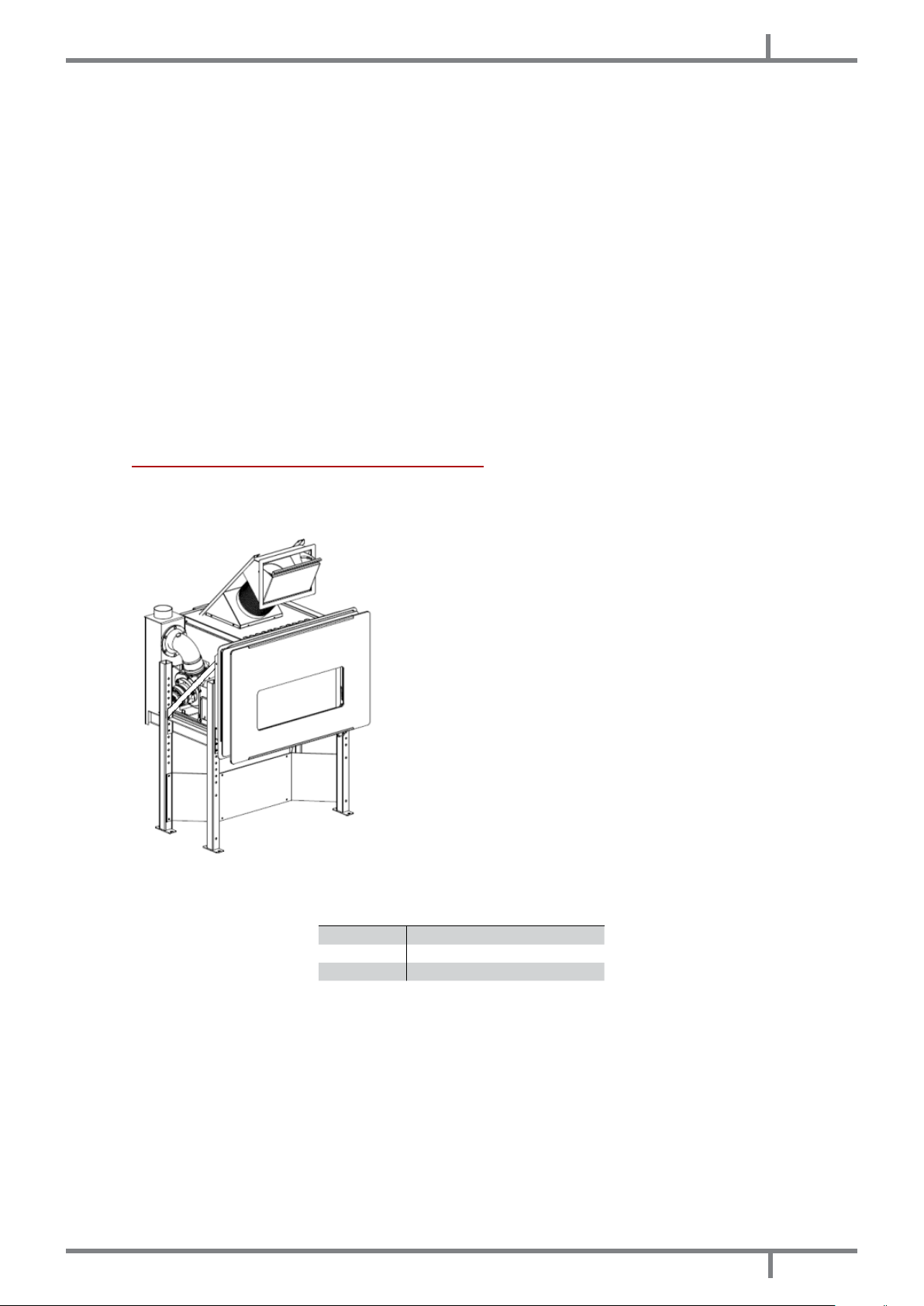
NL
• Til het inbouwelement met behulp van de handgrepen p (zie Fig. 18 op pag. 54) ên plaats het in de
geleiders van het frame Fig. 19 op pag. 54.
Fig. 20 - Schroef achteraan om het inbouwelement te bevesti-
gen
Fig. 21 - Schroef vooraan om het inbouwelement te bevestigen
• Draai de 2 bevestigingsschroeven aan beide zijden van het inbouwelement aan, zoals aangegeven in Fig.
20 op pag. 55 en Fig. 21 op pag. 55.
• Duw het inbouwelement in het frame.
11.6 INSTALLATIE MET EXTERNE BEKLEDING
• Het is mogelijk om naar believen met vormen te bekleden, mits de correcte uitvoering wordt nageleefd zoals
aangegeven in ALGEMENE INSTALLATIE op pag. 52 en in de instructies hierna.
Fig. 22 - Volledige structuur Fig. 23 - Opgedeelde structuur
LEGENDE Fig. 23 op pag. 55
1 Steunpoten
2 Frame van het inbouwelement
3 Inbouwelement
• Verwijder het inbouwelement zoals beschreven in VERWIJDERING VAN HET INBOUWELEMENT op pag. 53.
EOLO - COMFORT 80
55
Page 56

NL
Fig. 24 - Posities voor de bevestiging
• Bevestig de poten op de vloer en breng het frame van het inbouwelement op de gewenste hoogte door de
poten bij te regelen (H 55÷660 mm); blokkeer daarna met de schroeven in de voorziene geleiders (zie foto
Fig. 24 op pag. 56).
• Het is verplicht om de poten van het draagframe op het onderstel te bevestigen met metalen pluggen die
een gewicht van 50 kg per poot kunnen dragen.
Wanneer het inbouwelement gemonteerd op de geleiders wordt uitgetrokken, bestaat er
gevaar voor omkantelen!
Controleer of het frame van het inbouwelement op de vloer is bevestigd.
56
Fig. 25 - Installatie met bekleding
EOLO - COMFORT 80
Page 57

LEGENDE Fig. 25 op pag. 56
1 Valse plafond beschermen
2 Pleisterwerk van het plafond tegen hitte beschermen
3 Verluchtingsrooster bovenaan met minimale opening 400 cm
4 Zelfdragend metalen frame
5 Inlaat voor de verbrandingslucht
6 Opening om pellets te laden
7 Verluchtingsrooster onderaan met minimale opening 400 cm
8 Plaat ter bescherming van de vloer
9 Afvoerpijp Ø80 mm
10 Rookkanaal Ø80 mm met minimaal 1 m. lengte verticaal
11 Rookkanaal minimum Ø120 mm
12 Inspectiedeurtje rookkanaal met hermetische dichting
13 Metselwerk
14 Vloer
15 Plafond met houten balken
16 Inzetelement
17 Isolatie tussen muur en rookkanaal minimum 200 mm op de volledige diameter
18 Inlaat voor verbrandingslucht
19 Minimale afstand tussen de houten balken en het rookkanaal = 0,5 m.
2
voor uitlaat van de natuurlijke convectieve warme lucht
2
voor inlaat van de natuurlijke convectieve koude lucht
• Bouw een metalen frame ter ondersteuning van de bekledingspanelen (4).
• Het gewicht van de metalen structuur niet op het frame van het inbouwelement overdragen.
• Bekleed het metalen frame met panelen in niet-brandbaar materiaal.
NL
Maak een opening van min. 400 cm2 aan de onderkant (7) en bovenkant (3) van de
panelen voor de interne luchtcirculatie.
• Het laden van pellets kan plaatsvinden door het inbouwelement uit te trekken wanneer de machine uit staat
of door de installatie te voorzien van de laadklep (6).
• De klep om pellets te laden kan aan de voorkant of aan de zijkant geïnstalleerd worden, door de exibele
buis Ø160 mm afhankelijk van de noodwendigheden te verlengen.
11.7 INSTALLATIE IN EEN BESTAANDE HAARD
• Het inbouwelement kan in een bestaande haard worden ingebouwd mits de afstanden en de correcte
uitvoering zoals aangegeven in ALGEMENE INSTALLATIE op pag. 52 en de instructies hierna worden
nageleefd.
• Verwijder het inbouwelement zoals beschreven in VERWIJDERING VAN HET INBOUWELEMENT op pag. 53.
• Zet de poten vast op de laagste hoogte (H 55 mm) en blokkeer ze met de schroeven in de voorziene geleiders.
• Het is verplicht om de poten van het draagframe op het onderstel te bevestigen met metalen pluggen die
een gewicht van 50 kg per poot kunnen dragen.
Wanneer het inbouwelement gemonteerd op de geleiders wordt uitgetrokken, bestaat er
gevaar voor omkantelen!
Controleer of het frame van het inbouwelement correct op het onderstel is bevestigd.
Controleer of de uitlaat van de warme lucht bovenaan niet afgesnoerd wordt, zie Fig. 26
op pag. 58.
Maak een opening van 400 cm2 aan de onderkant en bovenkant van de haard voor de
interne luchtcirculatie.
• Het laden van pellets kan plaatsvinden door het inbouwelement uit te trekken wanneer de machine uit staat
of door de installatie te voorzien van de laadklep.
• De klep om pellets te laden kan aan de voorkant of aan de zijkant geïnstalleerd worden, door de exibele
buis Ø160 mm afhankelijk van de noodwendigheden te verlengen.
EOLO - COMFORT 80
57
Page 58

NL
Fig. 26 - Installatie in een bestaande haard
LEGENDE Fig. 26 op pag. 58
1 Valse plafond beschermen
2 Pleisterwerk van het plafond tegen hitte beschermen
3 Verluchtingsrooster bovenaan met minimale opening 400 cm
4 Deector warme lucht (minimale ruimte 30 cm)
5 Inlaat voor de verbrandingslucht
6 Vuurplaat van de haard
7 Verluchtingsrooster onderaan met minimale opening 400 cm
8 Verluchtingsopening van 400 cm2 voor circulatie van natuurlijk geconvecteerde koude lucht
9 Afvoerpijp Ø80 mm
10 Rookkanaal Ø80 mm met minimaal 1 m. lengte verticaal
11 Rookkanaal = Ø120 mm
12 Rookkanaal Ø100 mm
13 Metselwerk
14 Vloer
15 Plafond met houten balken minimale afstand tot het rookkanaal = 0,5 m.
16 Inzetelement
17 Opening om pellets te laden
18 Blokkeerring
2
voor uitlaat van de natuurlijke convectieve warme lucht
2
voor inlaat van de natuurlijke convectieve koude lucht
11.8 ELEKTRISCHE AANSLUITING
Belangrijk: het apparaat moet door een geautoriseerd technicus geïnstalleerd worden!
• De elektrische aansluiting vindt plaats met een kabel met stekker op een elektrisch stopcontact dat geschikt
is om de lading en de specieke spanning van ieder afzonderlijk model te verdragen, zoals aangeduid wordt
in de tabel met technische gegevens (zie KENMERKEN op pag. 77).
58
EOLO - COMFORT 80
Page 59

NL
• De stekker moet gemakkelijk toegankelijk zijn wanneer het apparaat geïnstalleerd is.
• Controleer bovendien of het elektriciteitsnet over een doeltreffende aardverbinding beschikt: als die niet
aanwezig of niet efciënt is, zorg dan voor een aardverbinding in overeenstemming met de wettelijke
voorschriften.
• Sluit de voedingskabel eerst op de achterkant van de kachel aan (zie ) en daarna op een elektrisch
wandstopcontact.
• De O/I-hoofdschakelaar (zie ) mag alleen geactiveerd worden om de kachel in te schakelen. Het is raadzaam
de hoofdschakelaar in alle andere gevallen uitgeschakeld te laten.
• Gebruik geen verlengsnoer.
• Als de voedingskabel beschadigd is, moet deze door een geautoriseerd technicus vervangen worden.
• Wanneer de kachel gedurende lange tijd niet gebruikt zal worden, is het raadzaam de stekker uit het
elektrische wandstopcontact te halen.
11.9 AANSLUITING EXTERNE THERMOSTAAT
De kachel is reeds werkzaam via een thermostaatsonde die zich binnenin de kachel zelf bevindt. Als u dat wenst
kan de kachel op een externe omgevingsthermostaat aangesloten worden. Deze handeling moet door een
geautoriseerd technicus uitgevoerd worden.
• Externe thermostaat: stel een "SET TEMP RUIMTE" van 7°C op de kachel in.
• Externe chronothermostaat: stel een "SET TEMP RUIMTE" van 7°C op de kachel in en schakel in menu 03-01 de
chronofuncties uit "ACTIVEER CHRONO" ("OFF").
12
GEBRUIK
12.1 INLEIDING
Voor het beste rendement met het laagste verbruik moeten onderstaande aanwijzingen opgevolgd worden.
• De inschakeling van de pellets vindt heel gemakkelijk plaats als de installatie correct is en het rookkanaal
efciënt werkt.
• Schakel de kachel gedurende minstens 2 uur in op Vermogen 1 om het materiaal waaruit de ketel en de
vuurhaard bestaat in staat te stellen zich aan te passen aan de interne elastische krachten die uitgeoefend
worden.
• De vetresten van de fabricage en de lakken kunnen tijdens de eerste uren werking geuren en rook verspreiden:
er wordt geadviseerd het vertrek te luchten omdat deze geuren en rook schadelijk voor mens en dier kunnen
zijn.
• Door gebruik van de kachel kan de lak vanbinnen in de verbrandingskamer veranderingen ondergaan.
Dit fenomeen kan aan verschillende oorzaken worden toegeschreven: overmatige oververhitting van de
kachel, chemische stoffen die in minderwaardige pellets aanwezig zijn, slechte trek van de schoorsteen, enz.
Bijgevolg kan de hechting van de lak in de verbrandingskamer niet worden gegarandeerd.
De programmeringswaarden van 1 tot 5 zijn van tevoren door de fabrikant ingesteld en
kunnen alleen door een geautoriseerd technicus veranderd worden.
12.2 BEDIENINGSPANEEL
ELEMENT VAN HET PANEEL BESCHRIJVING
EOLO - COMFORT 80
P1 en P2: wanneer men zich in de werkwijze set temperatuur bevindt, verhogen of
verlagen ze de waarde van de thermostaat van min. 6°C tot max. 41°C. Houd P1
ingedrukt om de temperatuur van de rookgassen in de afvoerpijp te zien. Beide hebben
programmeringsfuncties.
P3: om naar set temperatuur en naar het menu van de parameters van gebruiker en
technicus te gaan.
P4: inschakeling en uitschakeling, deblokkering van eventuele alarmen en verlaten van
de programmering.
59
Page 60
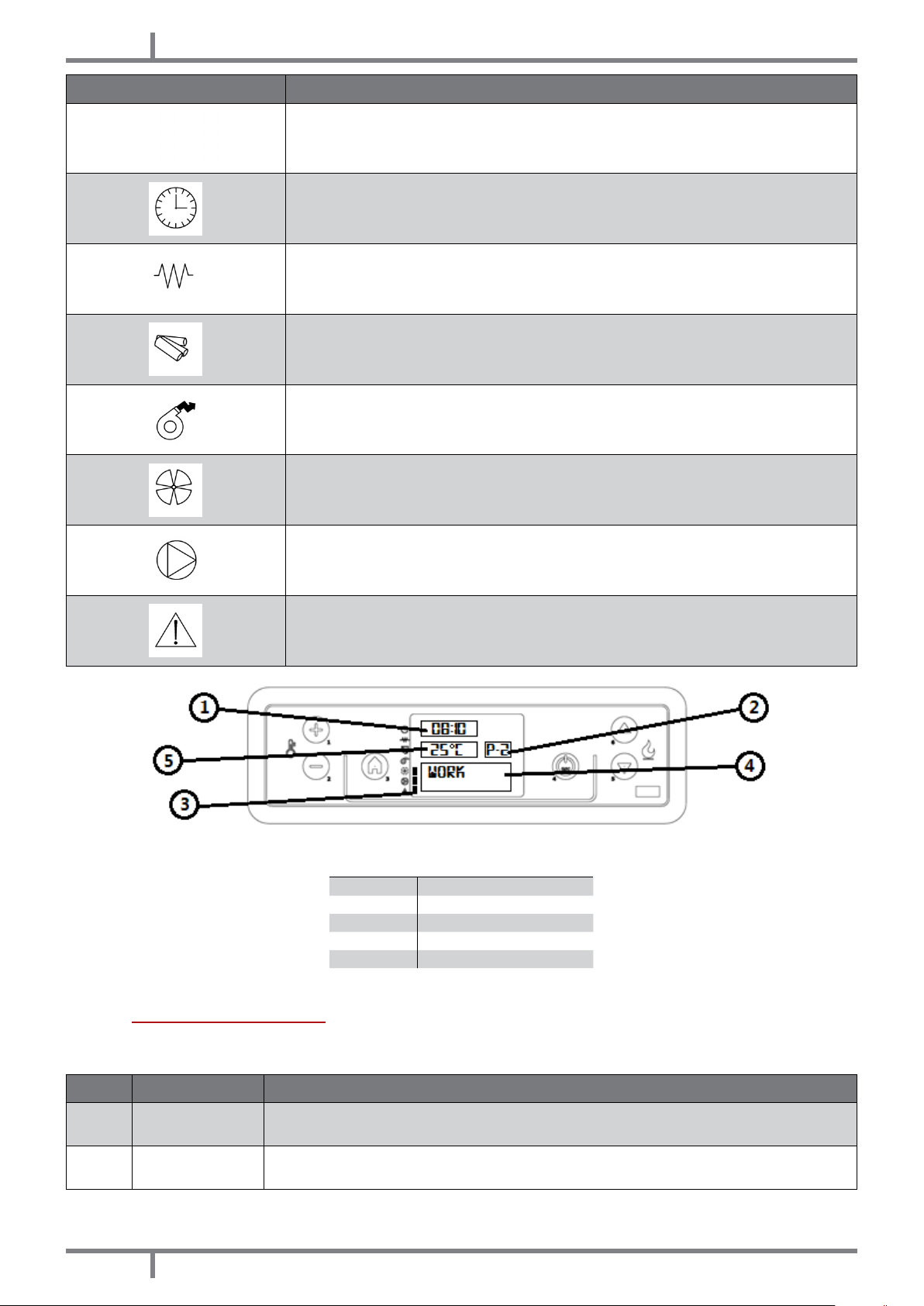
NL
ELEMENT VAN HET PANEEL BESCHRIJVING
P5 en P6: verhogen en verlagen het warmtevermogen van 1 tot 5.
Tijdprogrammering: actief.
Rookgassenafzuiger: actief
Transportschroef: actief.
Ontvangst gegevens van afstandsbediening
Ventilator warmtewisselaar: actief
-
Alarm: actief
LEGENDA Fig. 27 op pag. 60
Fig. 27 - Controledisplays LCD
1 Uuwerk
2 Mogendheid
3 Uitbreiding
4 Bericht
5 Temperatuur
12.3 GEBRUIKERSMENU
Door slechts één keer op toets P3 te drukken, wordt toegang verkregen tot het beheer van de gebruikersparameters.
Druk op de toetsen P5 en P6 om deze langs te lopen. We hebben:
POS. VERWIJST NAAR BESCHRIJVING
1
2 SET CLOCK
FAN ADJUST
(supplementary)
60
Niet gebruikt.
Stelt de datum en de tijd in. De kaart is uitgerust met een lithiumbatterij die de klok een
autonomie van 3/5 jaar verschaft. Zie INSTELLINGEN KLOK op pag. 62.
EOLO - COMFORT 80
Page 61

POS. VERWIJST NAAR BESCHRIJVING
Druk één keer op toets P3: de tekst "CHRONO ENABLE" verschijnt. Druk nog een keer op P3
3 SET CHRONO
en gebruik de toetsen P1 en P2 om "OFF" of "ON" in te stellen. Zie voor de programmering
van de dag, het weekend of de week DAGPROGRAMMERING op pag. 62. LET OP: niet
activeren als de STANDBY-functie actief is!
NL
4
5 STAND-BY MODE
6
7 INITIAL LOAD
8 STOVE STATE
9 TECHNICA SETTING Alleen voor de geautoriseerde technicus
10 FLAME SETTING Maakt het mogelijk de vlam in te stellen op grond van de trek van het rookkanaal.
SELECT
LANGUAGE
BUZZER MODE
(audio alarm)
Druk één keer op toets P3 en kies de gewenste taal met de toetsen P1 en P2.
Activeert een functie die de fase van uitschakeling start als de ingestelde
omgevingstemperatuur langer dan 10 minuten overschreden is. Als de omgevingstemperatuur
met meer dan 2°C gedaald is, wordt de kachel opnieuw automatisch ingeschakeld,
vertrekkende van STARTEN op pag. 61. Druk één keer op toets P3 en stel "OFF" of "ON" in
met de toetsen P1 en P2. LET OP: niet activeren als de CHRONO-functie actief is!
Druk één keer op toets P3 en stel "OFF" of "ON" in met de toetsen P1 en P2.
Wanneer de kachel voor het eerst ingeschakeld moet worden, is de transportschroef
geheel leeg. Voer zo nodig een voorlading uit door op toets P3 te drukken. Druk vervolgens
op P1 om te starten en op P4 om dit te onderbreken.
Geeft alle parameters weer die verband houden met de status waarin de kachel zich
bevindt: het is een menu voor de geautoriseerde technicus.
12.4 STARTEN
Wij herinneren u eraan dat de eerste inschakeling door gekwaliceerd en geautoriseerd technisch personeel
uitgevoerd moet worden, dat controleert of alles volgens de van kracht zijnde normen geïnstalleerd is en dat
de werking controleert.
• Als in de verbrandingskamer boekjes, handleidingen enz..... aanwezig zijn, verwijder deze dan.
• Controleer of de deur goed gesloten is.
• Controleer of de stekker in het elektrische stopcontact gestoken is.
• Controleer voordat u de kachel inschakelt of de vuurpot schoon is.
• Om de kachel te starten, houdt u toets P4 enkele ogenblikken ingedrukt tot "START" en dan "PREHEATI WAIT"
getoond wordt: nu begint de voorverwarming van de inschakelweerstand. Na circa 2 minuten wordt "PELLET
LOAD, FIRE WAIT" getoond, begint de transportschroef de pellets te laden en wordt de verwarming van de
weerstand voortgezet. Wanneer de temperatuur voldoende hoog is (na circa 7-10 minuten), kan men de
inschakeling als voltooid beschouwen en verschijnt "FLAME PRESENT" op het display.
• Na beëindiging van de fase "FLAME PRESENT" neemt de regeleenheid de modaliteit "WORK" aan en toont het
geselecteerde warmtevermogen en de omgevingstemperatuur. Het is in deze fase dat de toetsen P5 en P6
het vermogen van de kachel van 1 tot 5 regelen.
• Als de waarde van de omgevingstemperatuur de limiet overschrijdt die met het toetsenbord bij set
temperatuur ingesteld is, wordt het warmtevermogen op het minimum gezet en wordt de tekst "WORK,
MODULA" getoond. Als de omgevingstemperatuur onder de ingestelde temperatuur daalt, keert de kachel
terug naar het ingestelde vermogen.
12.5 INSTELLING KACHEL
De kachel is ingesteld op grond van de gegevens van het rookkanaal en van de gebruikte pellets, volgens
de technische kenmerken (zie KENMERKEN op pag. 77). Als de gegevens niet overeenstemmen kan de
geautoriseerde technicus de kachel in stellen.
• Als de pellets klein zijn en het warmtevermogen groter is (bijvoorbeeld: door vuurpot met aanslag), verlaag
dan de val van de pellets in het menu "FLAME SETTING", druk op P3 " PELLET TYPE", druk nog een keer op P3
"PELLETS LOAD" en verlaag met toets P2 de hoeveelheid pellets van -1 (gelijk aan -2%) tot -9 (gelijk aan -18%).
• Als het rookkanaal een lagere trek heeft (bijvoorbeeld: door zwakke vlam, vuil glas), verhoog dan de toeren
van de rookgassenmotor in het menu ""FLAME SETTING", druk op P5 "CHIMNEY TYPE", druk op P3 "FUME-EXT,
CHIMNEY " en verhoog met toets P1 de toeren van de rookgassenaanzuiger van +1 (gelijk aan 5%) tot +9
(gelijk aan +30%).
• Als het rookkanaal een grotere trek heeft (bijvoorbeeld: omdat pellets uit de vuurpot gehaald zijn), verlaag
de toeren van de rookgassenaanzuiger dan van -1 tot -9.
Let op of de waarde positief of negatief is.
EOLO - COMFORT 80
61
Page 62

NL
12.6 GEEN ONTSTEKING
Als de pellets niet ontstoken worden, wordt dit gesignaleerd door het alarm "NO IGNITION".
• Als de omgevingstemperatuur lager is dan 10°C is de bougie niet in staat de ontstekingsfase te activeren.
Om de bougie in deze fase te helpen, moet u nog wat pellets in de vuurpot doen en een stukje brandend
ontstekingsmateriaal op de pellets leggen (zoals bijvoorbeeld het Italiaanse product Diavolina).
Na een mislukte ontsteking moeten de opeengehoopte pellets uit de vuurpot gehaald
worden alvorens de kachel opnieuw te starten.
• Teveel pellets in de vuurpot, of vochtige pellets, of een vuile vuurpot, maken het ontsteken moeilijk, veroorzaken
witte, dichte rook die schadelijk voor de gezondheid is en kunnen explosies in de verbrandingskamer tot
gevolg hebben. Men dient daarom tijdens de ontstekingsfase niet voor de kachel te blijven staan als witte,
dichte rook waargenomen wordt.
Als de vlam na enkele maanden zwak is en/of oranje van kleur, of als het glas de neiging
vertoont steeds erg zwart te worden, of de vuurpot de neiging vertoont een aanslag te
vormen, reinig dan de kachel, reinig de rookleiding en reinig het rookkanaal.
12.7 GEEN ENERGIE
• Na een black-out van de elektrische energie van minder dan 5 seconden, keert de kachel terug naar het
vermogen waarop hij ingesteld was.
• Na een black-out van de elektrische energie van meer dan 5 seconden, treedt de kachel de fase "COOLING
WAIT" binnen. Na aoop van de koelfase gaat de kachel automatisch opnieuw van start met de diverse
fasen (zie STARTEN op pag. 61).
12.8 SET TEMPERATUUR
• Om de omgevingstemperatuur te wijzigen, volstaat het op de toetsen P1 en P2 te drukken, al naargelang de
gewenste temperatuur, en "SET TEMP ROOM" weer te geven.
• Druk één enkele keer op toets P1 om de ingestelde temperatuur te laten weergeven.
12.9 TEMPERATUUR ROOKGASSEN
Om de temperatuur van de rookgassen bij de uitgang van de afvoerpijp te controleren, volstaat het toets P2
ingedrukt te houden.
12.10 UITSCHAKELING
Om de kachel uit te schakelen, houdt u toets P4 ingedrukt: op display A verschijnt de tekst "FINAL CLEANING".
Na circa 15-20 minunten gaat ook de rookgassenafzuiger uit (dit gebeurt altijd, onafhankelijk van het feit of de
kachel warm of koud is). Op het beeldscherm "OFF".
Als de pellets van slechte kwaliteit zijn (ze bevatten lijm, olie, lak, residu van plastic of zijn
kruimig), kan tijdens de werking een residu langs de pelletafvoerleiding gevormd worden. Is
de kachel eenmaal uitgeschakeld dan kan dit residu hele kleine gloeiende kooltjes vormen
die opwaarts langs de leiding de pellets in de voorraadbak kunnen bereiken, deze kunnen
doen verkolen en zo een dichte, schadelijke rook in het vertrek kunnen veroorzaken. Houd
de voorraadbak altijd afgesloten met diens deksel. Mocht de buis vuil blijken te zijn, reinig
deze dan (zie INLEIDING op pag. 66).
12.11 INSTELLINGEN KLOK
• Druk op toets P3 en vervolgens op toets P5 tot het menu (02) "SET CLOCK" geaccentueerd wordt.
• Druk één keer op P3 (DAY) en selecteer met toetsen P1 en P2 de dag van de week (maandag, dinsdag,
woensdag, donderdag, vrijdag, zaterdag en zondag).
• Druk een tweede keer op toets P3 (HOURS) en stel het uur in met toetsen P1 en P2.
• Druk een derde keer op toets P3 (MINUTES) en stel de minuten in met toetsen P1 en P2.
• Druk een vierde keer op toets P3 (DAY) en stel de dag van de maand in (1, 2, 3 ...29, 30, 31) met toetsen P1
en P2.
• Druk een vijfde keer op toets P3 (MONTH) en stel de maand in met toetsen P1 en P2.
• Druk een zesde keer op de toets P3 (YEAR) en stel het jaar in met toetsen P1 en P2.
• Druk twee keer op P4 om de programmering te verlaten.
12.12 DAGPROGRAMMERING
Maakt het mogelijk de functies van de dag-chronothermostaat in te schakelen, uit te schakelen en in te stellen.
Druk op toets P3 en vervolgens op toets P5 tot het menu (03) "SET CHRONO" weergegeven wordt. Druk één keer
62
EOLO - COMFORT 80
Page 63

NL
op toets P3 en selecteer met toetsen P5 en P6 "PROGRAM DAY". Druk één keer op P3 waarna "CHRONO DAY"
verschijnt. Stel met toetsen P1 en P2 "OFF" of "ON" in.
Het is mogelijk twee tijdzones voor de werking in te stellen die door de ingestelde tijden afgebakend worden.
Na "CHRONO DAY":
• Druk op P5: nu verschijnt de tekst "START 1". Voer met toetsen P1 en P2 de waarde van het tijdstip van
inschakeling in, of "OFF".
• Druk op P5: nu verschijnt de tekst "STOP 1". Voer met toetsen P1 en P2 de waarde van het tijdstip van
inschakeling in, of "OFF".
• Druk op P5: nu verschijnt de tekst "START 2". Voer met toetsen P1 en P2 de waarde van het tijdstip van
inschakeling in, of "OFF".
• Druk op P5: nu verschijnt de tekst "STOP 2". Voer met toetsen P1 en P2 de waarde van het tijdstip van
inschakeling in, of "OFF".
• Druk drie keer op toets P4 om het menu te verlaten.
12.13 WEEKENDPROGRAMMERING
Maakt het mogelijk de functies van de dag-chronothermostaat in te schakelen, uit te schakelen en in te stellen.
Druk op toets P3 en vervolgens op toets P5 tot het menu (03) "SET CHRONO" weergegeven wordt. Druk één keer
op toets P3 en selecteer met toetsen P5 en P6 "PROGRAM WEEK-END".
Druk één keer op P3 waarna "CHRONO WEEK-END" verschijnt. Stel met toetsen P1 en P2 "OFF" of "ON" in.
Het is mogelijk twee tijdzones voor de werking in te stellen die door de ingestelde tijden afgebakend worden en
alleen voor de zaterdag en de zondag geldig zijn.
Na "CHRONO WEEK-END":
• Druk op P5: nu verschijnt de tekst "START 1 WEEK-END". Voer met toetsen P1 en P2 de waarde van het tijdstip
van inschakeling in, of "OFF".
• Druk op P5: nu verschijnt de tekst "STOP 1 WEEK-END". Voer met toetsen P1 en P2 de waarde van het tijdstip
van inschakeling in, of "OFF".
• Druk op P5: nu verschijnt de tekst "START 2 WEEK-END". Voer met toetsen P1 en P2 de waarde van het tijdstip
van inschakeling in, of "OFF".
• Druk op P5: nu verschijnt de tekst "STOP 2 WEEK-END". Voer met toetsen P1 en P2 de waarde van het tijdstip
van inschakeling in, of "OFF".
• Druk drie keer op toets P4 om het menu te verlaten.
12.14 WEEKPROGRAMMERING
Maakt het mogelijk de functies van de dag-chronothermostaat in te schakelen, uit te schakelen en in te stellen.
Druk op toets P3 en vervolgens op toets P5 tot het menu (03) "SET CHRONO" weergegeven wordt. Druk één
keer op toets P3 en selecteer met toetsen P5 en P6 "PROGRAM WEEK". Druk één keer op P3 waarna "WEEKLY
CHRONO" verschijnt. Stel met toetsen P1 en P2 "OFF" of "ON" in.
Het is mogelijk twee tijdzones voor de werking in te stellen die door de ingestelde tijden afgebakend worden.
Na "WEEKLY CHRONO":
Druk op P5: nu verschijnt de tekst "START PROG-1". Voer met toetsen P1 en P2 de waarde van het tijdstip van
inschakeling in, of "OFF".
Druk op P5: nu verschijnt de tekst "STOP PROG-1". Voer met toetsen P1 en P2 de waarde van het tijdstip van
uitschakeling in, of "OFF".
• Druk op P5: nu verschijnt de tekst "MONDAY PROG-1". Stel met toetsen P1 en P2 "OFF" of "ON" in.
• Druk op P5: nu verschijnt de tekst "TUESADY PROG-1". Stel met toetsen P1 en P2 "OFF" of "ON" in.
• Druk op P5: nu verschijnt de tekst "WEDNESDA PROG-1". Stel met toetsen P1 en P2 "OFF" of "ON" in.
• Druk op P5: nu verschijnt de tekst "THURSDAY PROG-1". Stel met toetsen P1 en P2 "OFF" of "ON" in.
• Druk op P5: nu verschijnt de tekst "FRIDAY PROG-1". Stel met toetsen P1 en P2 "OFF" of "ON" in.
• Druk op P5: nu verschijnt de tekst "SATURDAY PROG-1". Stel met toetsen P1 en P2 "OFF" of "ON" in.
• Druk op P5: nu verschijnt de tekst "SUNDAY PROG-1". Stel met toetsen P1 en P2 "OFF" of "ON" in.
Ga nu verder door op toets P5 te drukken en alle vorige handelingen te herhalen voor Prog-2, Prog-3, Prog-4.
• Druk drie keer op toets P4 om het menu te verlaten.
12.15 PELLETS BIJVULLEN
Fig. 28 - Slechte opening de pelletszak Fig. 29 - Correct opening de pelletszak
EOLO - COMFORT 80
63
Page 64

NL
Vermijd het om de verzamelbak met pellets te vullen als de kachel in werking is.
• Breng de zak met brandstof niet in aanraking met de warme delen van de kachel.
• Giet geen brandstofresten (onverbrande kool) - het afval van inschakelingen in de vuurpot - in de voorraadbak.
12.16 SENSOR PELLETS
Het toestel is uitgerust met een sensor die waarschuwt wanneer de pellets bijna op zijn.
• Bericht op het display "PELLET RESERVE", het toestel gaat over naar energiebesparing en stelt zich op vermogen
P1.
• Wanneer de reserve op is (na circa 10 minuten), geeft het display het bericht "PELLET OVER" weer; het toestel
gaat verder met de eindschoonmaak en schakelt uit.
12.17 AFSTANDSBEDIENING
• De kachel kan bediend worden met de afstandsbediening.
• Voor de werking heeft men 1 batterij van het type Lithium battery CR 2025 nodig.
De gebruikte batterijen bevatten - voor de omgeving - schadelijke metalen en moeten dus in
speciale batterijbakken geëlimineerd worden.
Fig. 30 - Afstandsbediening
LEGENDA Fig. 30 op pag. 64
Toets 1 Verhoogt de gewenste temperatuur
Toets 2 Verlaagt de gewenste temperatuur
Toets 3 On / off
Toets 4 Menu
Toets 5 Verlaagt het vermogensniveau van 5 tot 1
Toets 6 Verhoogt het vermogensniveau van 1 tot 5
13
VEILIGHEIDSVOORZIENINGEN
13.1 INLEIDING
De veiligheidsvoorzieningen hebben tot taak de risico's op persoonlijk letsel, dierlijk letsel of materiële schade
weg te nemen.
Het is verboden deze voorzieningen onklaar te maken en de ingreep voor een eventuele reparatie door niet
geautoriseerd personeel doet de garantie en de aansprakelijkheid van de fabrikant vervallen.
13.2 ALARM "BLACK OUT"
"ALARM ACTIVE" "AL 1 - BLACK OUT": onderbreking van de voeding tijdens de ontsteking.
• Verricht een reset van de fout met toets P4. De kachel voert een fase "FINAL CLEANING" en "OFF" uit.
• Reinig de vuurpot en herstart de kachel met toets P4.
64
EOLO - COMFORT 80
Page 65

NL
13.3 ALARM "FUME PROBE"
Er is een sonde op de rookgassenafvoerpijp aangesloten die de bedrijfstemperatuur continu bewaakt.
"ALARM ACTIVE" "AL 2 - FUME PROBE": de sonde is beschadigd of afgesloten
• Verricht een reset van de fout met toets P4. De kachel voert een fase "FINAL CLEANING" en "OFF" uit.
• Controleer het type fout aan de hand van ALARMEN op pag. 70.
• Reinig de vuurpot en herstart de kachel met toets P4.
13.4 ALARM "HOT FUME"
Als de rookgassensonde een temperatuur van meer dan 180°C meet op de afvoer, verschijnt de tekst "RIS" op
het display. Op dit punt wordt het brandstofdebiet (pellets) verlaagd tot fase 1.
Deze functie heeft tot doel de waarden binnen de van tevoren ingestelde gegevens terug te brengen. Als de
temperatuur om diverse redenen niet verlaagd maar verhoogd wordt, wordt bij 210°C de tekst "ALAR HOT TEMP"
"AL 3 - HOT TEMP" weergegeven en start de kachel de fase van uitschakeling.
• Verricht een reset van de fout met toets P4. De kachel voert een fase "FINAL CLEANING" en "OFF" uit.
• Controleer het type fout aan de hand van ALARMEN op pag. 70.
• Reinig de vuurpot en herstart de kachel met toets P4.
13.5 ALARM "FAN FAILURE"
"ALARM ACTIVE" AL 4 - FAN FAILURE": de rookgassenafzuiger is kapot.
• Verricht een reset van de fout met toets P4. De kachel voert een fase "FINAL CLEANING" en "OFF" uit.
• Controleer het type fout aan de hand van ALARMEN op pag. 70.
• Reinig de vuurpot en herstart de kachel met toets P4.
13.6 ALARM "FAILED IGNITION"
"ALARM ACTIVE" "AL 5 - FAILED IGNITION": de temperatuur is onvoldoende voor de ontsteking.
• Verricht een reset van de fout met toets P4. De kachel voert een fase "FINAL CLEANING" en "OFF" uit.
• Controleer het type fout aan de hand van ALARMEN op pag. 70.
• Reinig de vuurpot en herstart de kachel met toets P4.
13.7 ALARM "NO PELLET"
Als de rookgassensensor bij de afvoer een temperatuur detecteert die lager is dan de minimumdrempel, dan
wordt de tekst "ALARM ACTIVE" "AL 6 - NO PELLETS" getoond.
• Verricht een reset van de fout met toets P4. De kachel voert een fase "FINAL CLEANING" en "OFF" uit.
• Controleer het type fout aan de hand van ALARMEN op pag. 70.
• Reinig de vuurpot en herstart de kachel met toets P4.
13.8 ALARM "THERMAL SAFETY"
In de voorraadbak is een thermostaat met handmatige terugstelling geïnstalleerd die in werking treed als de
temperatuurgang van de voorraadbak de toegestane limieten overschrijdt zodat de mogelijkheid uitgesloten
wordt dat de pellets binnenin de voorraadbak door oververhitting in brand kunnen raken.
"ALARM ACTIVE" "AL 7 - THERMAL SAFETY": dee thermostaat onderbreken de elektrische voeding naar de
transportschroef.
• Verricht een reset van de fout met toets P4. De kachel voert een fase "FINAL CLEANING" en "OFF" uit.
• Controleer het type fout aan de hand van ALARMEN op pag. 70.
• Schroef het zwarte kapje los, druk op het knopje en schroef het beschermkapje weer vast
• Reinig de vuurpot en herstart de kachel met toets P4.
13.9 ALARM "FAILURE DEPRESS"
Er is een drukschakelaar op de ketel aangesloten die de onderdruk controleert. In enkele modellen kachels is
een microschakelaar in de vuurdeur geïnstalleerd die de opening ervan detecteert.
"ALARM ACTIVE" "AL 8 - FAILURE DEPRESS": dee thermostaat onderbreken de elektrische voeding naar de
transportschroef.
• Verricht een reset van de fout met toets P4. De kachel voert een fase "FINAL CLEANING" en "OFF" uit.
• Controleer het type fout aan de hand van ALARMEN op pag. 70.
• Reinig de vuurpot en herstart de kachel met toets P4.
13.10 ALARM "OPEN DOOR"
"ALARM ACTIVE "AL 9 - OPEN DOOR": de drukschakelaar en/of de vuurdeur, die niet correct gesloten is,
onderbreken de elektrische voeding naar de transportschroef.
• Verricht een reset van de fout met toets P4. De kachel voert een fase "FINAL CLEANING" en "OFF" uit.
• Controleer het type fout aan de hand van ALARMEN op pag. 70.
• Reinig de vuurpot en herstart de kachel met toets P4.
EOLO - COMFORT 80
65
Page 66

NL
14
ONDERHOUD
14.1 INLEIDING
Voor een lange levensduur van de kachel moet regelmatig een algehele reiniging uitgevoerd worden zoals
vermeld wordt in onderstaande paragrafen.
• De rookafvoerleidingen (rookleiding + rookkanaal + schoorsteenpot) moeten altijd door een geautoriseerde
specialist gereinigd, geveegd en gecontroleerd worden in overeenstemming met de plaatselijke regelgeving,
met aanduiding van de fabrikant en met de richtlijnen van uw verzekeringsmaatschappij.
• Bij afwezigheid van plaatselijke voorschriften en richtlijnen van uw verzekeringsmaatschappij is het nodig
de reiniging van de rookleiding, het rookkanaal en de schoorsteenpot minstens één keer per jaar te laten
uitvoeren.
• Het is bovendien nodig om de verbrandingskamer minstens één keer per jaar te laten reinigen en de
pakkingen na te laten kijken, de motoren en de ventilatoren te laten reinigen en het elektrische gedeelte te
laten controleren.
Al deze werkzaamheden moeten tijdig geprogrammeerd worden in overleg met de
geautoriseerde technische assistentiedienst.
• Na een lange periode van onbruik dient men te controleren of de rookgassenafvoerpijp geen obstructies
bevat, alvorens de kachel in te schakelen.
• Als de kachel op continue en intense wijze gebruikt wordt, moet het gehele systeem (met inbegrip van de
schoorsteen) vaker gereinigd en gecontroleerd worden.
• Voor de eventuele vervanging van beschadigde delen dient u de geautoriseerde verkoper om originele
vervangingsonderdelen te vragen.
14.2 REINIGING VUURPOT EN ASLADE
De vuurpot en de aslade moeten om de 2 dagen gereinigd worden.
• Open de deur.
Fig. 31 - Verwijdering vuurpot Fig. 32 - Reiniging vuurpot Fig. 33 - Positionering ruit vuurpot
• Verwijder de vuurpot (zie Fig. 31 op pag. 66) uit diens zitting en leeg hem door de as weg te gooien.
• Reinig zo nodig met een puntig voorwerp de gaten die door afzettingen verstopt geraakt zijn (zie Fig. 32 op
pag. 66).
• Maak de ruit schoon en plaats die in de vuurpot terug in de voorziene openingen ter ondersteuning (zie Fig.
33 op pag. 66).
Fig. 34 - Verwijdering aslade Fig. 35 - Reiniging met essenwisser
• Verwijder de aslade (zie Fig. 34 op pag. 66) uit diens zitting en leeg hem door de as weg te gooien.
66
EOLO - COMFORT 80
Page 67

NL
• Reinig ook het valgat van de pellets met een essenwisser (zie Fig. 35 op pag. 66).
• De as moet in een metalen bak met hermetisch gesloten deksel gedaan worden en deze bak mag nooit in
aanraking met brandbaar materiaal komen (als hij bijvoorbeeld op een houten vloer gezet wordt) omdat de
as in de bak de kool nog heel lang brandend houdt).
• Pas wanneer de as gedoofd is kan ze weggegooid worden bij het organische afval.
• Let op de vlam, als deze rood wordt, zwak is of zwarte rook afgeeft: in dat geval is de vuurpot door afzettingen
verstopt en moet gereinigd worden (zie Fig. 32 op pag. 66). Indien versleten moet hij vervangen worden.
14.3 REINIGING VAN DE VERBRANDINGSKAMER
De verbrandingskamer en de kamer waarin de aslade zit moeten iedere week worden schoongemaakt.
Fig. 36 - Reiniging ruimte vuurpot Fig. 37 - Reiniging ruimte aslade Fig. 38 - Schoonmaak bovenste deel
• Open de deur.
• Neem de vuurpot en de aslade weg en maak ze schoon.
• Maak schoon door de as weg te zuigen die zich in de verbrandingskamer (zie Fig. 36 op pag. 67) en in de
kamer van de aslade (zie Fig. 37 op pag. 67) heeft opgestapeld.
• Zuig ook de as weg die zich in het bovenste deel heeft opgestapeld van de leidingen die in de
verbrandingskamer aanwezig zijn (zie Fig. 38 op pag. 67).
14.4 REINIGING VOORRAADBAK EN TRANSPORTSCHROEF
Bij iedere bijvulling met pellets moet de eventuele aanwezigheid van poeder/zaagsel of ander afval op de
bodem van de voorraadbak gecontroleerd worden. Is dergelijk afval aanwezig, dan moet het verwijderd
worden met behulp van een alleszuiger (zie Fig. 39 op pag. 67).
Fig. 39 - Reiniging van de voorraadbak en transportschroef
Het rooster dat de handen bescherming biedt, mag nooit uit zijn zitting verwijderd worden.
Reinig de bodem van de voorraadbak en het zichtbare deel van de transportschroef
grondig en uitsluitend zoals op de foto getoond wordt (zie Fig. 39 op pag. 67).
14.5 REINIGING ROOKGASSENKAMER
Reinig de rookgassenkamer om de 4/8 weken.
EOLO - COMFORT 80
67
Page 68

NL
Fig. 40 - Rookgassenkamer
• Maak de 2 gele stops los (zie Fig. 13 op pag. 53) en trek het inbouwelement tot halverwege uit zijn frame.
• Draai de 2 schroeven los van het verzinkte paneel dat de kamer van de rookgassen afsluit, dit paneel bevindt
zich onder het inbouwelement (zie Fig. 40 op pag. 68).
• Reinig met een alleszuiger en zuig de as af die zich in de kamer opeengehoopt heeft.
• Voer na de reiniging de werkzaamheden in omgekeerde volgorde uit en controleer de intacte staat en de
efciëntie van de pakking: laat de pakking indien nodig door een geautoriseerde technicus vervangen.
14.6 REINIGING ROOKLEIDING
Reinig het afvoersysteem iedere maand.
Fig. 41 - Reiniging rookleiding
• Maak de 2 gele stops los (zie Fig. 13 op pag. 53) en trek het inbouwelement tot halverwege uit zijn frame.
• Zuig de afvoer van de rookgassen uit zoals aangegeven in Fig. 41 op pag. 68.
14.7 REINIGING VAN DE ROOKGASSENAFZUIGER
Reinig jaarlijks de rookgassenafzuiger en ontdoe deze van de as of de stof die tot gevolg hebben dat de
schoepen in onbalans raken en meer geluid maken.
Fig. 42 - Reiniging rookgassenafzuiger:
fase1
Fig. 43 - Fase 2 Fig. 44 - Fase 3
• Volg de procedure die aangeduid wordt in Fig. 42 op pag. 68, Fig. 43 op pag. 68 en Fig. 44 op pag. 68.
68
EOLO - COMFORT 80
Page 69

NL
14.8 REINIGING ROOKGASSENDOORGANG
Reinig jaarlijks de rookgassendoorgangen.
Fig. 45 - Verwijdering 1e paneel Fig. 46 - Verwijdering 2e paneel
• Draai de schroeven los van het verzinkte paneel, dat zich aan de kant van het inbouwelement bevindt Fig.
45 op pag. 69).
• Schroef het andere verzinkte paneel los (zie Fig. 46 op pag. 69) en zuig de binnenkant goed schoon.
14.9 JAARLIJKSE REINIGING VAN DE ROOKGASSENLEIDINGEN
Reinig deze jaarlijks en verwijder het roet met gebruik van borstels.
De reiniging moet door een kachel- en schoorsteenspecialist uitgevoerd worden die de rookleiding, het
rookkanaal en de schoorsteenpot reinigt, de efciëntie ervan nakijkt en een schriftelijike verklaring afgeeft waarin
vermeld wordt dat het systeem veilig is. Deze werkzaamheden moeten minstens één keer per jaar uitgevoerd
worden.
14.10 ALGEMENE REINIGING
Voor de reiniging van de externe en interne delen van de kachel dient u geen gebruik te maken van staalsponsjes,
zoutzuur of andere corroderende en schurende producten.
14.11 REINIGING VAN GELAKTE METALEN ONDERDELEN
Voor de reiniging van de gelakte metalen onderdelen dient u een zachte doek te gebruiken. Gebruik nooit
ontvettende substanties zoals alcohol, verdunners, aceton of benzine omdat deze de lak op onherstelbare wijze
beschadigen.
14.12 VERVANGING VAN DE PAKKINGEN
Mochten de pakkingen van de vuurdeur, de voorraadbak of de rookgassenkamer versleten raken, dan moeten
ze vervangen worden door een gautoriseerde technicus om de goede werking van de kachel te garanderen.
Gebruik uitsluitend originele reserveonderdelen.
14.13 REINIGING VAN HET GLAS
Het keramische glas van de vuurdeur is bestand tegen 700°C maar niet tegen temperatuurschommelingen.
De eventuele reiniging met in de handel verkrijgbare producten voor glas moet plaatsvinden wanneer het glas
EOLO - COMFORT 80
69
Page 70

NL
koud is om te voorkomen dat het kan exploderen.
Er wordt geadviseert de glas van de vuurdeur alle dagen te reinigen!
14.14 REINIGING VAN HET GLAS
Bij breuk moet die absoluut worden vervangen vooraleer de kachel opnieuw te gebruiken.
Ga als volgt te werk om te vervangen:
Fig. 47 - Verwijder de schroeven Fig. 48 - Verwijder de deurproelen
• Draai de schroeven los uit de proelen die de ruit op hun plaats houden (zie Fig. 47 op pag. 70).
• Verwijder de proelen bovenaan en onderaan (zie Fig. 48 op pag. 70).
• Verwijder de beschadigde ruit en vervang alleen met een oorspronkelijk reserveonderdeel. Controleer of de
pakking niet aangetast is; indien nodig laten vervangen.
• Hermonteer de proelen en draai de schroeven opnieuw aan.
15
IN GEVAL VAN ONGEMAKKEN
15.1 ALARMEN
Vóór iedere test en/of ingreep van de geautoriseerde technicus heeft deze technicus zelf
de plicht te controleren of de parameters van de elektronische kaart overeenkomen met
de referentietabel die hij in bezit heeft.
In geval van twijfel omtrent het gebruik van de kachel dient u ALTIJD de geautoriseerde
technicus te contacteren om onherstelbare schade te voorkomen.
ALARM OORZAAK OPLOSSING INGREEP
AL 1 - BLACK
OUT
AL 2 - EXHAUST
PROBE
70
Onderbreking elektrische
energie tijdens de fase
van inschakeling
De temperatuursonde
van de rookgassen is
afgesloten
De temperatuursonde
van de rookgassen is
defect
Reinig de vuurpot en schakel opnieuw in.
Voer een revisie van de kachel uit.
Vervang de rookgassensonde.
EOLO - COMFORT 80
Page 71
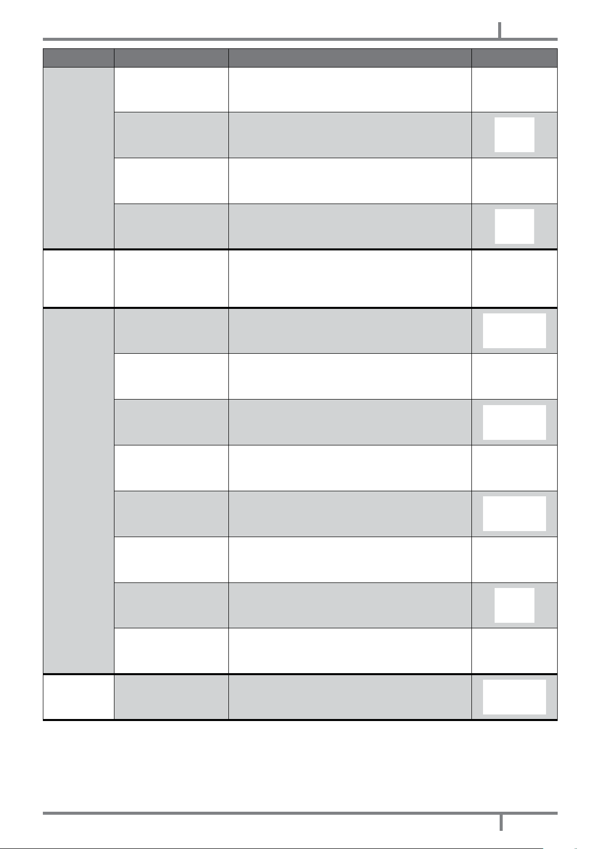
ALARM OORZAAK OPLOSSING INGREEP
NL
AL 3 - HOT
EXHAUST
AL 4 - FAN
FAILURE
De rookgassensonde is
defect
De elektronische kaart is
defect
De warmtewisselaarventilator voor de
omgeving werkt niet
De waarde van de
lading van de pellets is te
hoog "fase 5"
De rookgassenafzuiger is
defect
De voorraadbak is leeg Vul de voorraadbak.
De vuurpot is niet
gereinigd
Vervang de rookgassensonde.
Vervang de elektronische kaart.
Vervang de omgevingsventilator.
Regel de lading van de pellets.
De pellets kunnen ook branden dankzij de onderdruk
van het rookkanaal, zonder behulp van de afzuiger. Laat
de rookgassenafzuiger onmiddellijk vervangen. Het kan
schadelijk voor de gezondheid zijn om de kachel zonder
afzuiger te laten werken.
Reinig de vuurpot.
AL 5 - NO
IGNITION
AL 6 - NO
PELLET
De ontstekingsdrempel
is niet bereikt door de
sonde
De inschakelbougie is
defect
De buitentemperatuur is
te laag
Vochtige pellets
De thermische sonde is
geblokkeerd
De elektronische kaart is
defect
De voorraadbak is leeg Vul de voorraadbak.
Reinig de vuurpot en schakel opnieuw in. (Bel een
geautoriseerde technicus als het probleem aanhoudt).
Vervang de inschakelweerstand.
Herstart de kachel.
De pellets moeten in een droge plaats bewaard worden.
Controleer dit.
Vervang de thermische sonde.
Vervang de elektronische kaart.
EOLO - COMFORT 80
71
Page 72
NL
ALARM OORZAAK OPLOSSING INGREEP
AL 7 - THERMAL
SAFETY
De ketel heeft een te
hoge temperatuur
De warmtewisselaarventilator voor de
omgeving werkt niet
Tijdelijke onderbreking
van de elektrische
energie
De thermostaat is defect Vervang de thermostaat.
De elektronische kaart is
defect
De afvoer is verstopt
Laat de kachel afkoelen: de thermostaat zal
opnieuw automatisch geactiveerd worden. (Bel een
geautoriseerde technicus als het probleem aanhoudt).
Vervang de omgevingsventilator.
werking veroorzaakt een oververhitting van de ketel en
de inwerkingtreding van de thermostaat. Laat de kachel
afkoelen en herstart de kachel.
Vervang de elektronische kaart.
De afvoerschoorsteen is gedeeltelijk of geheel verstopt.
Bel een kachel- en schoorsteenspecialist die een
controle van de kachelafvoer op de schoorsteenpot
uitvoert. Zorg dat onmiddellijk een reiniging plaatsvindt.
Het kan schadelijk voor de gezondheid zijn om de kachel
met verstopte schoorsteen te laten werken.
AL 8 - FAILURE
DEPRESS
De rookgassenafzuiger is
defect
De zitting voor het rubber
is verstopt
De drukschakelaar is
defect
De elektronische kaart is
defect
De schoorsteen is te lang
De
weersomstandigheden
zijn ongunstig
De pellets kunnen ook branden dankzij de onderdruk
van het rookkanaal, zonder behulp van de afzuiger. Laat
de rookgassenafzuiger onmiddellijk vervangen. Het kan
schadelijk voor de gezondheid zijn om de kachel zonder
afzuiger te laten werken.
Reinig het gat voor het rubber.
Vervang de drukschakelaar.
Vervang de elektronische kaart.
Raadpleeg een kachel- en schoorsteenspecialist en
controleer of de afvoerschoorsteen aan de voorschriften
voldoet: zie ROOKKANAAL op pag. 44.
Bij sterke wind kan er negatieve druk op de schoorsteen
staan. Controleer dit en schakel de kachel opnieuw in.
AL 9 - OPEN
DOOR
72
De vuurdeur is niet
correct gesloten
Microschakelaar
vuurdeur kapot of defect
Sluit de vuurdeur correct en controleer of de pakkingen
niet verslechterd zijn.
Vervang de microschakelaar van de vuurdeur.
EOLO - COMFORT 80
Page 73
15.2 OPLOSSING VAN DE PROBLEMEN
Vóór iedere test en/of ingreep van de geautoriseerde technicus heeft deze technicus zelf
de plicht te controleren of de parameters van de elektronische kaart overeenkomen met
de referentietabel die hij in bezit heeft.
In geval van twijfel omtrent het gebruik van de kachel dient u ALTIJD de geautoriseerde
technicus te contacteren om onherstelbare schade te voorkomen.
PROBLEEM OORZAAK OPLOSSING INGREEP
NL
Het
controledisplay
wordt niet
ingeschakeld
Er komen geen
pellets de
verbrandingska
mer binnen
De kachel is
zonder voeding
De veiligheidszekering
van de kaart is
doorgebrand
Het
controledisplay is
defect
De at-kabel is
defect.
De elektronische
kaart is defect
De voorraadbak
is leeg
De
transportschroef is
geblokkeerd door
een onbekend
object (zoals
spijkers)
-
De reductiemotor
van de
transportschroef is
kapot
Controleer of de stekker in het net gestoken is.
Vervang de veiligheidszekering in de kaart (4A-250V).
Vervang het controledisplay.
Vervang de at-kabel.
Vervang de elektronische kaart.
Vul de voorraadbak.
Reinig de transportschroef.
Vervang de reductiemotor.
EOLO - COMFORT 80
Controleer of het
display niet een
actief alarm toont
"ACTIVE ALARM"
Voer een revisie van de kachel uit.
73
Page 74
NL
PROBLEEM OORZAAK OPLOSSING INGREEP
Het vuur dooft en
de kachel stopt
De kachel werkt
op snelheid en het
display toont "FIRE
POT CLEANING"
De voorraadbak
is leeg
De
transportschroef is
geblokkeerd door
een onbekend
object (zoals
spijkers)
Slechte pellets Probeer andere soorten pellets uit.
De waarde van
de lading van de
pellets is te laag
"fase 1"
Controleer of het
display niet een
actief alarm toont
"ACTIVE ALARM"
Automatische
reiniging vuurpot
Vul de voorraadbak.
Reinig de transportschroef.
Regel de lading van de pellets.
Voer een revisie van de kachel uit.
De kachel gaat op het minimum staan en de
rookgassenafzuiger op het maximum. GEEN ENKEL
PROBLEEM!
De vlammen zijn
zwak en oranje
van kleur, de
pellets branden
niet correct en
het glas wordt vuil
zwart
De ventilatorwarmtewisselaar
blijft draaien, ook
al is de kachel
afgekoeld
Er is onvoldoende
verbrandingslucht
De afvoer is
verstopt
De kachel is
verstopt
De rookgassenafzuiger is kapot
De tempera
tuursonde van
de rookgassen is
defect
De elektronische
kaart is defect
-
Controleer de volgende punten: eventuele obstructies
voor de inlaat van de verbrandingslucht via de achter- of
onderkant van de kachel; regel of verwijder de eventuele
PVC-dop met register in de luchtinlaatbuis; verstopte
gaten van het rooster van de vuurpot en/of de ruimte
van de vuurpot met overmatige hoeveelheden as; laat
de schoepen van de afzuiger en het slakkenhuis daarvan
reinigen.
De afvoerschoorsteen is gedeeltelijk of geheel verstopt.
Bel een ervaren kachel- en schoorsteenspecialist die een
controle van de kachelafvoer tot en met de schoorsteenpot
uitvoert. Zorg dat onmiddellijk een reiniging plaatsvindt.
Zorg voor een interne reiniging van de kachel.
De pellets kunnen ook branden dankzij de onderdruk
van het rookkanaal, zonder behulp van de afzuiger. Laat
de rookgassenafzuiger onmiddellijk vervangen. Het kan
schadelijk voor de gezondheid zijn om de kachel zonder
afzuiger te laten werken.
Vervang de rookgassensonde.
Vervang de elektronische kaart.
74
EOLO - COMFORT 80
Page 75

PROBLEEM OORZAAK OPLOSSING INGREEP
De deurpakkingen
zijn defect of
kapot
Vervang de pakkingen.
NL
Er bevindt zich as
rondom de kachel
De kachel werkt
op snelheid en
het display toont
"WORK MODULATI"
De kachel werkt
op snelheid en het
display toont "HOT
FUME"
16
TECHNISCHE GEGEVENS
De buizen van de
rookleiding zijn
niet hermetisch
gesloten
De omgeving
stemperatuur is
bereikt
De
limiettemperatuur
voor de
uitlaat van de
rookgassen is
bereikt
Raadpleeg een kachel- en schoorsteenspecialist die
de aansluitingen onmiddellijk met siliconenkit voor hoge
temperaturen zal verzegelen en/of de buizen zelf zal
vervangen door buizen die aan de van kracht zijnde normen
voldoen. De kanalisering van de rookgassen is niet hermetisch
gesloten en kan de gezondheid schade berokkenen.
-
De kachel gaat op het minimum staan. GEEN ENKEL
PROBLEEM!
De kachel gaat op het minimum staan. GEEN ENKEL
PROBLEEM!
16.1 INFORMATIE VOOR DE REPARATIE
Wij verstrekken hier enige aanwijzingen voor de geautoriseerde technicus die hij dient op te volgen om toegang
tot de mechanische delen van de kachel te krijgen.
Fig. 49 - Stops Fig. 50 - Inbouwelement uittrekken
• Houd de gele haken naar beneden gedrukt (zie Fig. 49 op pag. 75) en trek het inbouwelement uit door die
over zijn geleiders te laten lopen (zie Fig. 50 op pag. 75).
Fig. 51 - Draai de bevestigingsschroeven van de carter los Fig. 52 - Carter verwijderen
• Draai de blokkerschroeven van de beschermcarter los (zie Fig. 51 op pag. 75) en neem de carter naar
EOLO - COMFORT 80
75
Page 76

NL
boven tie weg (zie Fig. 52 op pag. 75).
Fig. 53 - Blokkeerschroeven ventilator Fig. 54 - De ventilator verwijderen
• Draai de 2 blokkeerschroeven van de ventilator los (zie Fig. 53 op pag. 76) en neem de ventilator weg in
de richting aangegeven door de pijlen (zie Fig. 54 op pag. 76).
• Daarna heeft u toegang tot de koppeling van de silicone buis van de drukregelaar, tot de reductiemotor en
tot de ontstekingsbougie.
• Om de laadtransportschroef te vervangen en/of schoon te maken, moet u de drie bouten van de reductiemotor
losschroeven en de reductiemotor wegnemen, draai de twee schroeven onder de reductiemotor van de
transportschroef los en schroef ten slotte de twee interne bouten van de transportschroef los.
Fig. 55 - De zekering in de elektrische aansluiting verwijderen Fig. 56 - Vervanging van de zekering
• Om de zekering te vervangen van de elektrische aansluiting die zich achter het inbouwelement bevindt,
moet u een platte schroevendraaier in het deurtje steken en die eruit wippen Fig. 55 op pag. 76) om het
deurtje te verwijderen, daarna kunt u de zekering vervangen (zie Fig. 56 op pag. 76).
76
EOLO - COMFORT 80
Page 77

16.2 KENMERKEN
BESCHRIJVING EOLO COMFORT 80
BREEDTE 79,6 cm 79,6 cm
DIEPTE 60,1 cm 60,1 cm
HOOGTE 55,5 cm 55,5 cm
GEWICHT met voet 144 kg 144 kg
INGEVOERD THERMISCH VERMOGEN (Min/Max) 5,1 - 8,9 kW 5,1 - 8,9 kW
NOMINAAL THERMISCH VERMOGEN (Min/Max) 4,6 - 8 kW 4,6 - 8 kW
EFFICIËNTIE (Min/Max) 87,5 - 88 % 87,5 - 88 %
TEMPERATUUR ROOKGASSEN 109 - 157°C 109 - 157°C
MAXIMUM DEBIET VAN DE ROOKGASSEN (Min/Max) 6,8 - 7,6 g/s 6,8 - 7,6 g/s
NL
CO-EMISSIES (13% O
CO-EMISSIES
(Min/Max) 5,4 - 9,1 % 5,4 - 9,1 %
2
Gemiddeld CO-GEHALTE bij 13% O
Gemiddeld DEELTJESGEHALTE bij 13% O
) (Min/Max) 0,042 - 0,011 % 0,042 - 0,011 %
2
(Min/Max) 530 - 139 mg/Nm3 530 - 139 mg/Nm3
2
(Max) 20 mg/Nm
2
3
20 mg/Nm
3
ONDERDRUK SCHOORSTEEN (Min/Max) 12 Pa 12 Pa
MINIMUM VEILIGHEIDSAFSTAND van ontvlambaar materiaal 20 cm 20 cm
OP GEDEELD ROOKKANAAL NEE NEE
DIAMETER AFVOERPIJP ROOKGASSEN Ø80 mm Ø80 mm
BRANDSTOF Pellet Ø6-7 mm Pellet Ø6-7 mm
WARMTEVERMOGEN PELLETS 5 kWh/Kg 5 kWh/Kg
VOCHTGEHALTE PELLETS ≤ 10% ≤ 10%
VERWARMBAAR VOLUME 18/20°C Coëff. 0,045 kW (Min/Max) 110 -192 m
3
110 -192 m
3
UURVERBRUIK (Min/Max) 1,1 - 2,1 kg/h 1,1 - 2,1 kg/h
CAPACITEIT VOORRAADBAK 8 kg 8 kg
CAPACITEIT RESERVOIR + LAADOPENING (Min) 12 kg 12 kg
AUTONIMOE (Min/Max) 7,3 - 3,8 h 7,3 - 3,8 h
VOEDING 230V - 50Hz 230V - 50Hz
GEABSORBEERD VERMOGEN (Max) 340 W 340 W
GEABSORBEERD VERMOGEN INSCHAKELWEERSTAND 300 W 300 W
MINIMUM BUITENLUCHTINLAAT (laatste nuttige doorsnede) 80 cm
2
80 cm
KACHEL MET HERMETISCH GESLOTEN KAMER NEE NEE
BUITENLUCHTINLAAT VOOR - -
EOLO - COMFORT 80
2
77
Page 78

NOTE
Page 79

NOTE
Page 80

pellet stoves· wood stoves· wood cooking stoves
thermostoves· pellet fireplace inserts
pelletkachels· houtkachels· houtkeukens
thermokachel· open haard pellets
CADEL srl
FREEPOINT by Cadel
Via Foresto Sud, 7
31025 Santa Lucia di Piave (TV) - ITALY
tel. +39.0438.738669
fax +39.0438.73343
www.cadelsrl.com
Partner of:
Rev.01 - 2014
 Loading...