


FW-7890 Series
19” 2U Intel Dual Xeron Rackmount
Network Security Platform
User’s Manual

Copyright and Disclaimers
© Copyright 2004 - Lanner Electronics Inc.
All Rights Reserved
The contents in this publication have been thoroughly checked and considered accurate. The
publisher and manufacturer of this product, Lanner Electronics, is not responsible for any
violation of patents or other rights of third parties resulting from its use. Neither does Lanner
Electronics assume any responsibility for any inaccuracies contained in this manual, nor make
any commitment to keep the information in this document up-to-date.
Lanner reserves the right to make improvements to this document and/or this product at any
given time without notice.
No part of this document may be reproduced, stored in a retrieval system, or transmitted in any
form or by any means (electronic, mechanical, photocopying, recording, or otherwise, without
the formal consent from Lanner.
Trademark Acknowledgments
All products and/or brand names stated in this publication are the trademarks of their rightful
and associated companies.
Radio Frequency Emissions Notice
This equipment has been tested and found to comply with the digital device limits pursuant to
Part 15 of the FCC Rules. These limits are designed to provide reasonable protection against
harmful interference when operate in a commercial environment. This equipment generates,
uses, and can radiate radio frequency energy and, if not installed and used in accordance with
the instruction manual, may cause harmful interference to radio communications. Operation of
this equipment in a residential area may cause harmful interference, in which case the user will
be required to correct the interference at his expense.
ii

Federal Communications Commission (FCC) Statement
This Equipment has been tested and found to comply with the limits for a Class A
digital device, pursuant to Part 15 of the FCC rules. These limits are designed to
provide reasonable protection against harmful interference when the equipment is
operated in a commercial environment. This equipment generates, uses and can
radiate radio frequency energy and, if not installed and used in accordance with the
instructions, may cause harmful interference to radio communications. Operation of
this equipment in a residential area is likely to cause harmful interference in which
case the user will be required to correct the interference at his own expense.
iii

Safety Instructions
The following information relates to the safety of installation and maintenance personnel. Read
all instructions before attempting to unpack, install or operate this equipment, especially before
connecting the power adapter.
Please keep the following in mind as you unpack and install this equipment:
Always follow basic safety precautions to reduce the risk of fire, electrical shock and
injury to persons.
Do not apply power into FW-7890 before installation or when disconnecting this
product from its original system setup.
To prevent fire or shock hazard, do not expose the unit to rain, moisture or install this
product near water.
Locate a safe and dry location to place this product. Keep it away from wet
surfaces/surroundings.
Never push an object of any kind into this product through openings or empty slots, as
you may damage parts.
Do not attach the power supply cabling to building surfaces. Do not allow anything to
rest on the power cabling or allow it to be abused by persons walking on it.
Distance your working area from moist floors, ungrounded power extension cables, and
unavailable safety grounds.
Avoid installation of this product during a lighting storm.
Damages caused by electrostatic discharge may result in total or intermittent system
failures. To minimize the possibility of ESD damage, an anti-static strap is highly
recommended.
When cleaning or servicing this unit, avoid using highly toxic or aerosol cleaners. Use a
clean damp cloth when wiping its surfaces.
Do not place this device in a tight and sealed location. Place the unit where it can access
sufficient airflow to its vent holes (openings along its sides). Never block or cover these
openings.
Do not disassemble this product on your own.
iv

Getting Technical Assistance
Should you encounter questions or problems with your FW-7890, Lanner Electronics is ready
to assist you within the guidelines of our product support programs. First, check the electronic
product documentation for assistance. If you still cannot find the solution to your problem,
contact Lanner sales team with the following information handy:
FW-7890 model name
Part number
Local network configuration details
The abnormal behavior and/or error messages reported by your network system
Your questions, or a description of the problem you are experiencing
Call, fax, or e-mail Lanner Electronics for technical support.
Phone: 886-2-8692-6060
Fax: 886-2-8692-6101
E-mail: sales@lannerinc.com
About this Manual
This target audience of this manual includes users, administrators and technicians. This
publication is a useful reference when installing, configuring, operating and managing the
FW-7890. This breakdown and short descriptions of this manual’s contents are as follows:
Chapter 1 – Introduction provides an overview of the FW-7890 19” 2U
Rackmount network security appliance, including its related features,
application usage and technical specifications list. The chapter also
guides users through the pre and post installation process by listing safety
tips plus an overall detailed description of the control board and system
and their vital components.
Chapter 2 – Introduce Hardware Installation
Chapter 3 – Award BIOS Setup
Appendix A –summarizes the specification of the power supply
Appendix B –Watchdog Timer Introduction
Appendix C –Console Redirection
Appendix D– LCD Module and Key Pad
Appendix E –LAN Bypass Function
v

Table of Contents
Copyright and Disclaimers....................................................................................................ii
Trademark Acknowledgments...............................................................................................ii
Radio Frequency Emissions Notice..................................................................... ii
Safety Instructions............................................................................................... iv
Getting Technical Assistance.............................................................................. v
About this Manual................................................................................................ v
Table of Contents................................................................................................ vi
C h a p t e r 1.........................................................................................................................1
Getting Started 1
1.1 Introduction.................................................................................................. 1
1.1.1 Features...............................................................................................................................1
1.2 Technical Specifications.............................................................................. 2
1.3 Packing Contents........................................................................................ 3
1.4 MB-X77 System Board................................................................................4
1.4.1 Board Layout...............................................................................................................4
1.4.2 Jumper Settings and I/O Connector.....................................................................................5
1.4.3 Connector Pin Assignments.................................................................................................5
1.5 FW-7890 19” 2U Rackmount Firewall Mechanisms.................................... 20
1.5.1 Face Panel...........................................................................................................................20
1.5.3 Rear View.............................................................................................................................21
C h a p t e r 2.......................................................................................................................22
FW-7890 Hardware Installation Guide..............................................................................22
2.1 Hardware Installation Guide........................................................................ 22
Chapter 3..............................................................................................................................24
Award BIOS Setup..............................................................................................................24
3.1 BIOS Setup ................................................................................................. 24
3.2 Main Menu.................................................................................................... 25
3.3 Standard CMOS Features........................................................................... 27
3.4 Advanced BIOS Features............................................................................ 29
3.5 Advanced Chipset Features........................................................................ 31
3.6 Integrated Peripherals................................................................................. 32
3.7 Power Management Setup.......................................................................... 35
3.8 PnP/PCI Configuration ................................................................................ 37
3.9 PC Health Status......................................................................................... 38
3.10 Load Optimized Defaults........................................................................... 39
3.11 Supervisor/User Password Setting............................................................ 39
3.12 Save and Exit Setup.................................................................................. 40
3.13 Exit Without Saving .................................................................................... 40
Appendix A...........................................................................................................................41
Power Supply 41
Appendix B ..........................................................................................................................42
W atchdog Timer 42
A p p e n d i x C...................................................................................................................43
Console Redirection ............................................................................................................43
A p p e n d i x D ..................................................................................................................44
vi

LCD Module and Key Pad For FW-7890...........................................................................44
A p p e n d i x E...................................................................................................................44
LAN Bypass Function.........................................................................................................44
Warranty Policy 47
RMA Service 47
vii
1.1 Introduction
C h a p t e r 1
Getting Started
The FW-7890 is a 2U rackmount network security solution targeting the Enterprise market.
The FW-7890 supports dual socket 604 for Intel Xeon processor with 800MHz FSB. It is
designed with an Intel E7520 as its northbridge and Intel 6300ESB as its southbridge.; All
Gigabit ports to be connected from the northbridge with six PCI-E x4, ensuring maximum
throughput and performance. For extra flexibility and scalability, the FW-7890 has a Mini PCI
slot and two PCI-X slot, users can expand their specifications and performance by simply
adding add-on cards to the slot. FW-7890 has four built-in DDRII SDRAM DIMM sockets
onboard, enough for even the most intensive network security applications. The FW-7890 is a
powerful and flexible unit that can meet the vast and various hardware requirement and
performance needs of System Integrators, OEM customers and software developers.
1.1.1 Features
Listed below are the key features of FW-7890.
Supports 2 * SATA removable3.5” HDD
Supports Dual Socket 604 for Intel Xeon processor.Up to 3.6GHz at FSB 800MHz
Supports four DDR II DIMM socket (240-pin) up to 8GB DDR SDRAM.
Supports 12 Gigabit Ethernet ports, with six Marvell 88E8062 chipset. It supports 12
RJ-45 connectors
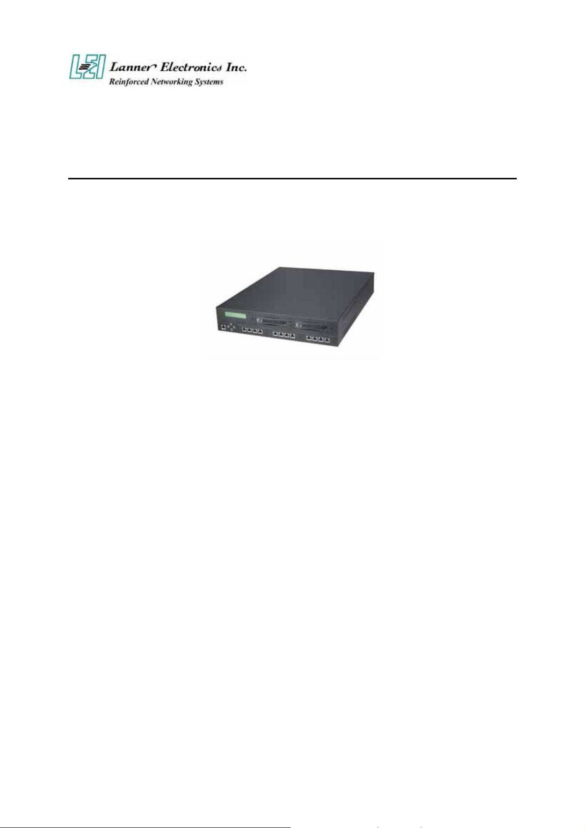
Figure 1 – FW-7890 Outlook
Supports Compact Flash, Console port(RJ-45), USB ports , 2* PCI-X Slot and Mini PCI.
19” 2U Rackmount network security appliance
Suitable Network applications; Virtual Private Network(VPN), Firewall, IDS,
Multi-Homing, Residential Gateway, Router and many more…
1
b
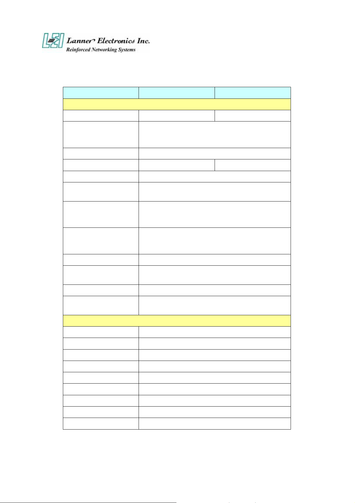
1.2 Technical Specifications
Model Name FW-7890A FW-7890B
SBC
SBC
CPU
Chipset
Security Processor
BIOS
Memory
Network interface
Storage
I/O Interface
Expansion Slot
MB-X77A MB-X77B
Dual Intel ® Xeon Processor, up to 3.6G with 1M L2,
800 FSB, and Hyper-Threading Technology with 64-
Extended Memory
Intel E7520 / Intel 6300ESB / Winbond W83627HF
Cavium CN1010 N/A
Award BIOS
Four 240-pin DDR-II DIMM socket, up to 8GB at
400 MHz (ECC, Registered Required)
Marvell 88E8062 PCI-E X 4 dual Gigabit controller
via six PCI-E X 4 interface up to 12 * gigabit RJ-45
Connector
Two CompactFlash TypeII Socket and Two
removable 3.5” Hard Driver Bay via Serial ATA
Interface
One RJ-45 Console port and One USB 2.0 Port
Two PCI-X Slots (Low Profile Only, 90mm width
maximum)
it
RTC
Power
Form Factor
Operating Temperature
Storage Temperature
Humidity
Chassis Material
Dimension
Net Weight
Certification
Software support
Internal RTC with LI battery
2U Redundant Power Supply with input Voltage :
100VAC-240VAC and Frequency :47Hz-63Hz
Mechanical/ Environmental
19” 2U Rackmount
o
0
C – 40 oC
o
-20
C – 70 oC
5% - 95% RH, non-condersing
SPGC
550x431x88 mm
22.2 KGS
CE, FCC CLASS A
Linux 6.5 and above, Windows 2000/2003/ XP
2

1.3 Packing Contents
Carefully unpack your package and make sure that you have the following items.
FW-7890 Network security Platform x 1 pcs
Console cable(RJ-45) x 1 pcs
1.8 meters long cross-over Ethernet cable x 1 pcs
1.8 meters long straight-through Ethernet cable x 1 pcs
Face panel name plate label x 1 pcs
Power cable x 2 pcs
Drivers and User’s Manual CD x 1 pcs
Screw Set
CPU Cooler x 2 pcs
Slid & Bracket Set
If you find anything missing or damaged, promptly contact your dealer for assistance.
3
1.4 MB-X77 System Board
MB-X77 is the system board bundled with the FW-7890 Network security platform. The
succeeding sections list all MB-X77 related jumper settings and connector pin assignments.
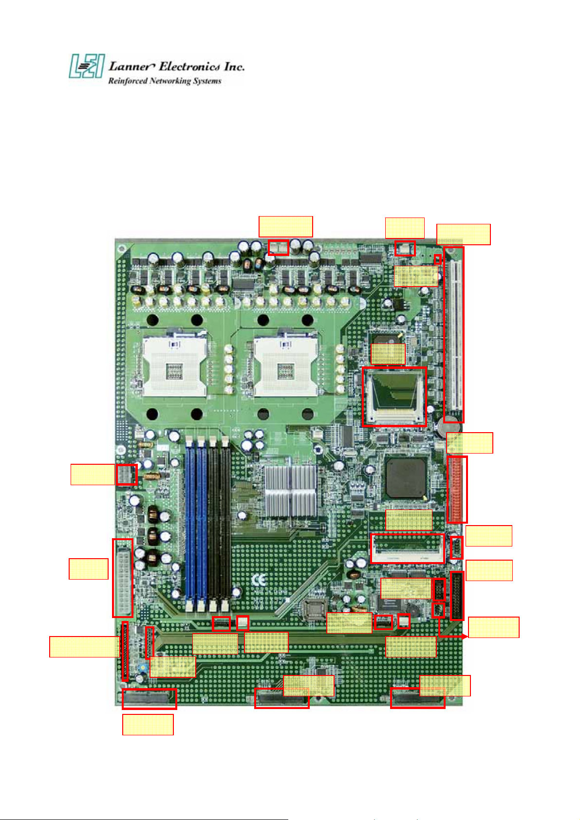
1.4.1 Board Layout
F AN1,2
CF1
F AN3
PME1
PCIXA1
PSBP1
PSC1
LUSBCOM1
PCIEA1
PLRS1
SATA2
SATA1
Figure 3 – MB-X77 Jumpers and Connectors
PS4S1
PCIEA2 PCIEA3
IDEB1
PCIB1
USBF1
LPTA1
COMB1
PKMB1
PS4S2`
4

1.4.2 Jumper Settings and I/O Connector
The onboard jumper settings and I/O connector of MB-X77 are custom-tailored to fit the
FW-7890 functionality. Changing the jumper settings may result in system malfunction or
unforeseen damages.
Jumper Settings and I/O Connector Summary for MB-X77
JUMPER FUNCTION
PLRS1 Power LED,HD LED,Reset,Speaker Connector(11 Pin 2.54mm)
PKMB1 PS/2 Keyboard & Mouse Connector (2x4 Header 2.54 mm)
CMOS1 Clear CMOS Data
IDEB1 IDE Interface Connector (40 Pin 2.54mm Pitch Header)
FAN 1 -3 3 Pin FAN Connector
FAN 4- 6 3 Pin FAN Connector
CF1 Compact Flash Connector
COMB1 Serial Port #2 Connector (Header)
LPTA1 Parallel Connector (26 Pin 2.00mm Pitch Header)
PSC1 24 Pin ATX Power Connector
PCIB1 124 Pin Mini PCI Socket
PCIXA1 184 Pin 3V PCIX Socket
PS4S1 - 2 4 Pin Power Connector
PS8P1 8 Pin Power Connector
SATAB1 180 SATA Connector
VR1 Control Sound
PME1 One PME1 Connector supports Wake-on-LAN
LUSBCOM1 BOX_HEADER_2X20_2.00_DIP
PCIEA1 -3 PCI EXPRESS CONNECTOR
USBF1 USB Port#1 & #2 Connector 2x5 Pin 2.54mm
PSWB1 ATX Power As AT Power Use Power Button
REDP1 2 Pin header for Redundant Power detect signal
1.4.3 Connector Pin Assignments
5
D
N
D
D
PLRS1:Power LED,HD LED,Reset,Speaker Connector(11 Pin 2.54mm)
PIN NO. DESCRIPTION
1 Power LED +
2 Power LED +
3 GND
4 HDD LED +
5 HDD LED 6 RESET SW +
7 RESET SW – (GND )
8 External Speaker 9 Internal Buzzer -
10 NC
11 External Speaker +
Default : 8-9 (ON) Internal Buzzer
PKMB1:PS/2 Keyboard & Mouse Connector (2x4 Header 2.54mm )
PIN NO.
DESCRIPTION
1 VCC 2 MSCLK
3 MSDATA 4 KEY
5 KBDATA 6 KEY
7
GND
PIN NO.
DESCRIPTION
8
KBCLK
1
3
5
7
2
4
6
8
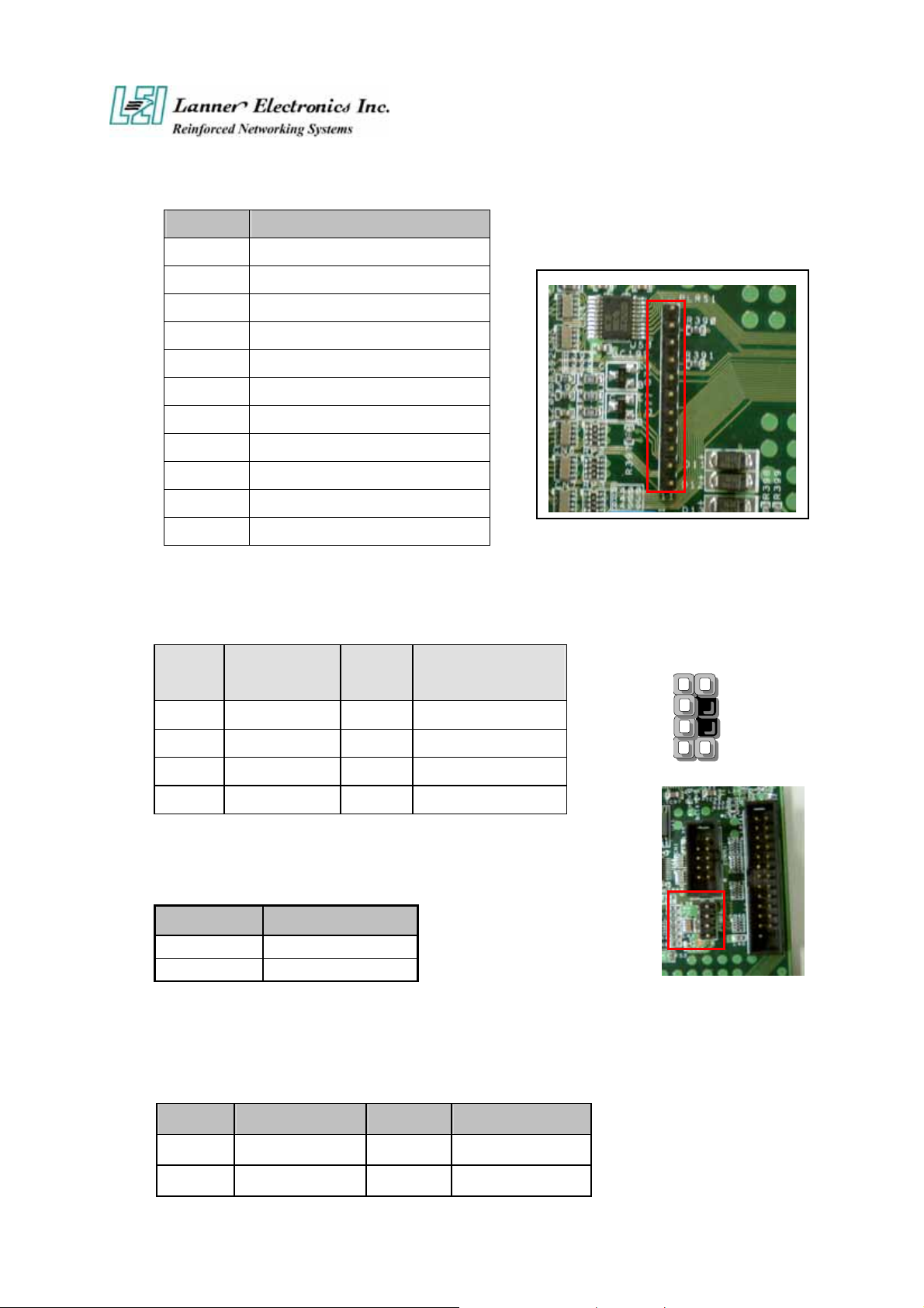
CMOS1:Clear CMOS Data
CMOS1 Description
1-2 Normal (Default)
2-3 Clear CMOS
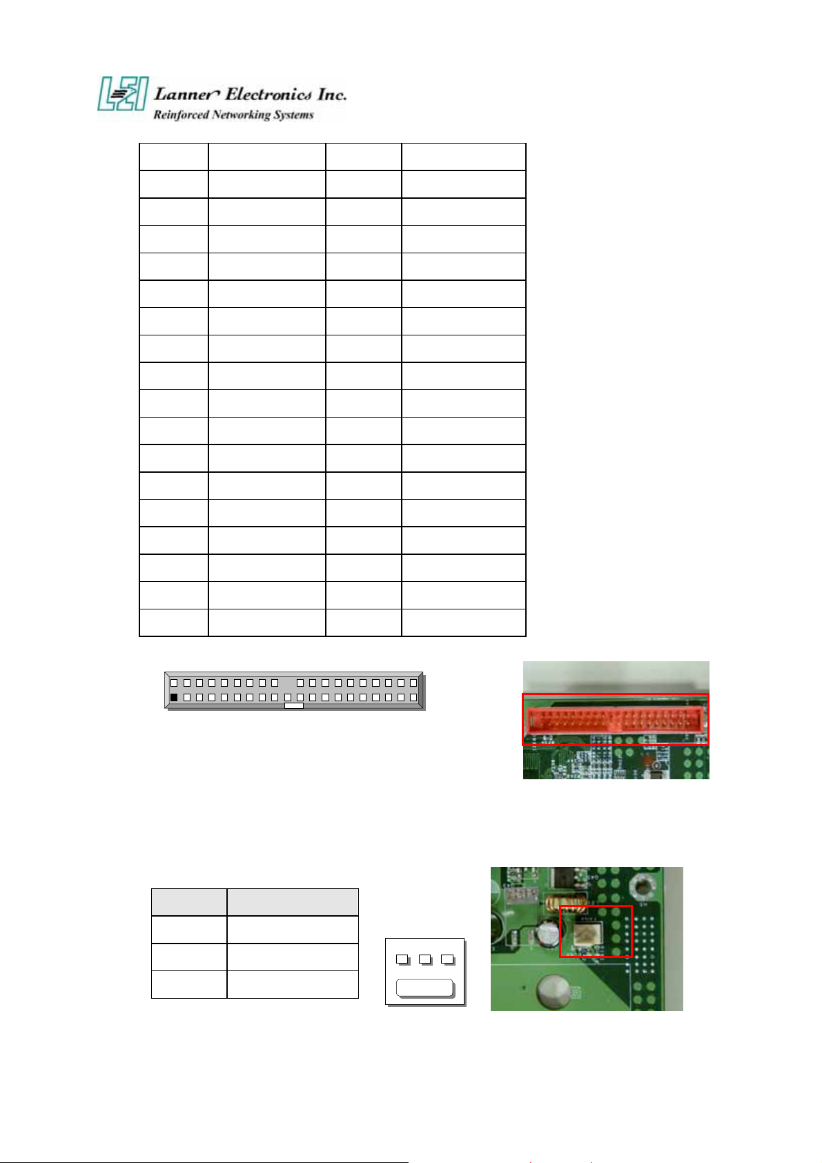
IDEB1 : IDE Interface Connector ( 40Pin 2.54mm Pitch Header )
PIN NO. DESCRIPTION PIN NO.
1 Reset # 2 Ground
3
ata 7 4
ESCRIPTIO
ata 8
6
D
D
D
D
D
D
D
D
D
D
D
D
D
D
K
D
D
C
S
S
S
H
H
H
F
AN
3
5
7
9
11
13
15
17
19 Ground 20
21
23 IOW # 24 Ground
25 IOR # 26 Ground
27 IOCHRDY 28 Ground
29
31 Interrupt 32 N
33
ata 6 6
ata 5 8
ata 4 10
ata 3 12
ata 2 14
ata 1 16
ata 0 18
MA REQ# 22 Ground
MA ACK # 30 Ground
A1 34 PD80P / SD80P
ata 9
ata 10
ata 11
ata 12
ata 13
ata 14
ata 15
EY
35
37
39
A0 36
DC CS0 # 38
DD Active LED # 40 Ground
A2
DC CS1 #
2
40
1
IDEB1
39
FAN1~3 : 3 Pin FAN Connector
Pin No. Description
1 Ground
2 +12V
1 2
3 NC
1
7
C
FAN4~6 : 3 Pin FAN Connector
Pin No. Description
1 Ground
2 +12V
3 FAN Status
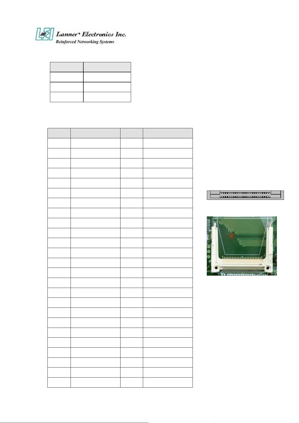
CF1:Compact Flash Connector
PIN DESCRIPTION PIN DESCRIPTION
1 GND 26 CD12 DATA3 27 DATA11
3 DATA4 28 DATA12
4 DATA5 29 DATA13
5 DATA6 30 DATA14
6 DATA7 31 DATA15
7 CE1# 32 CE2#
8 A10 33 VS1#
9 OE# 34 IOR#
10 A9 35 IOW#
11 A8 36 WE#
12 A7 37 READY#
13 CFVCC3 38 CFVCC3
14 A6 39 CSEL
15 A5 40 VS2#
16 A4 41 RESET
17 A3 42 WAIT#
18 A2 43 INPACK#
19 A1 44 REG#
50 26
25 1
F1
20 A0 45 DASP#
21 DATA0 46 DIAG#
22 DATA1 47 DATA8
23 DATA2 48 DATA9
24 WP 49 DATA10
25 CD2- 50 GND
8
)
)
(
)
)
(
)
(
)
)
)
6
5
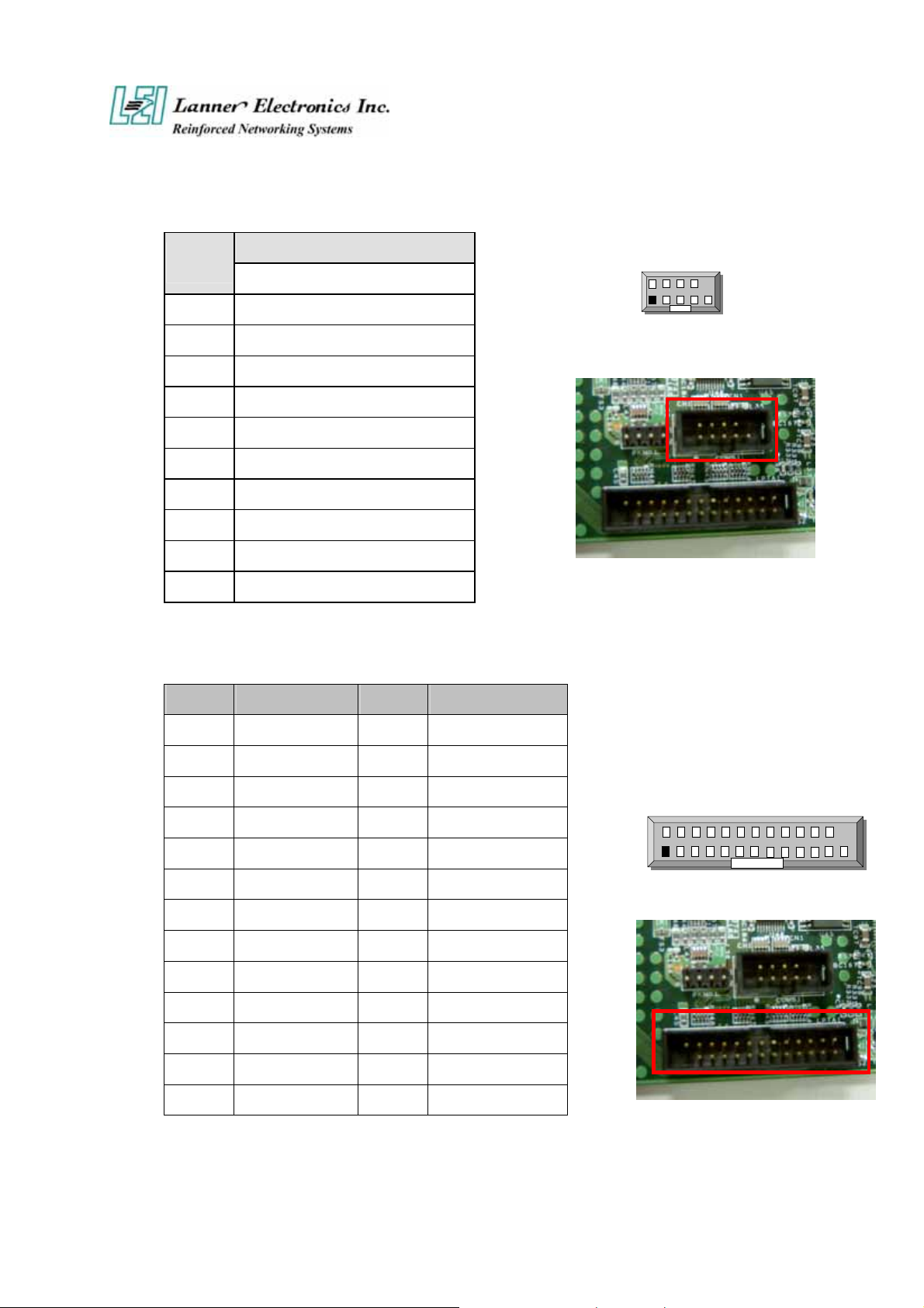
COMB1: Serial Port #2 Connector ( Header )
PIN NO
1 Data Carrier Detect (DCDB #
2 Data Set Ready (DSRB #
3 Receive Data
4 Request To Send (RTSB #
5 Transmit Data
6 Clear To Send
7 Data Terminal Ready (DTRB #
8 Ring Indicator (RIB #
9 Ground
10 KEY
DESCRIPTION
RS-232
RXDB
TXDB
CTSB #
2
1
COMB1
10
9
LPTA1:Parallel Connector (26 Pin 2.00mm Pitch Header )
PIN NO. DESCRIPTION PIN NO. DESCRIPTION
1 Strobe # 2 Auto Form Feed
3 Data0 4 Error #
5 Data1 6 Initialize #
7 Data2 8 Printer Select IN #
9 Data3 10 Ground
11 Data4 12 Ground
13 Data5 14 Ground
15 Data6 16 Ground
17 Data7 18 Ground
19 Acknowledge # 20 Ground
21 Busy 22 Ground
23 Paper Empty 24 Ground
25 Printer Select 26 KEY
2 2
LPTA11
2
PSC1:24 Pin ATX Power Connector
9
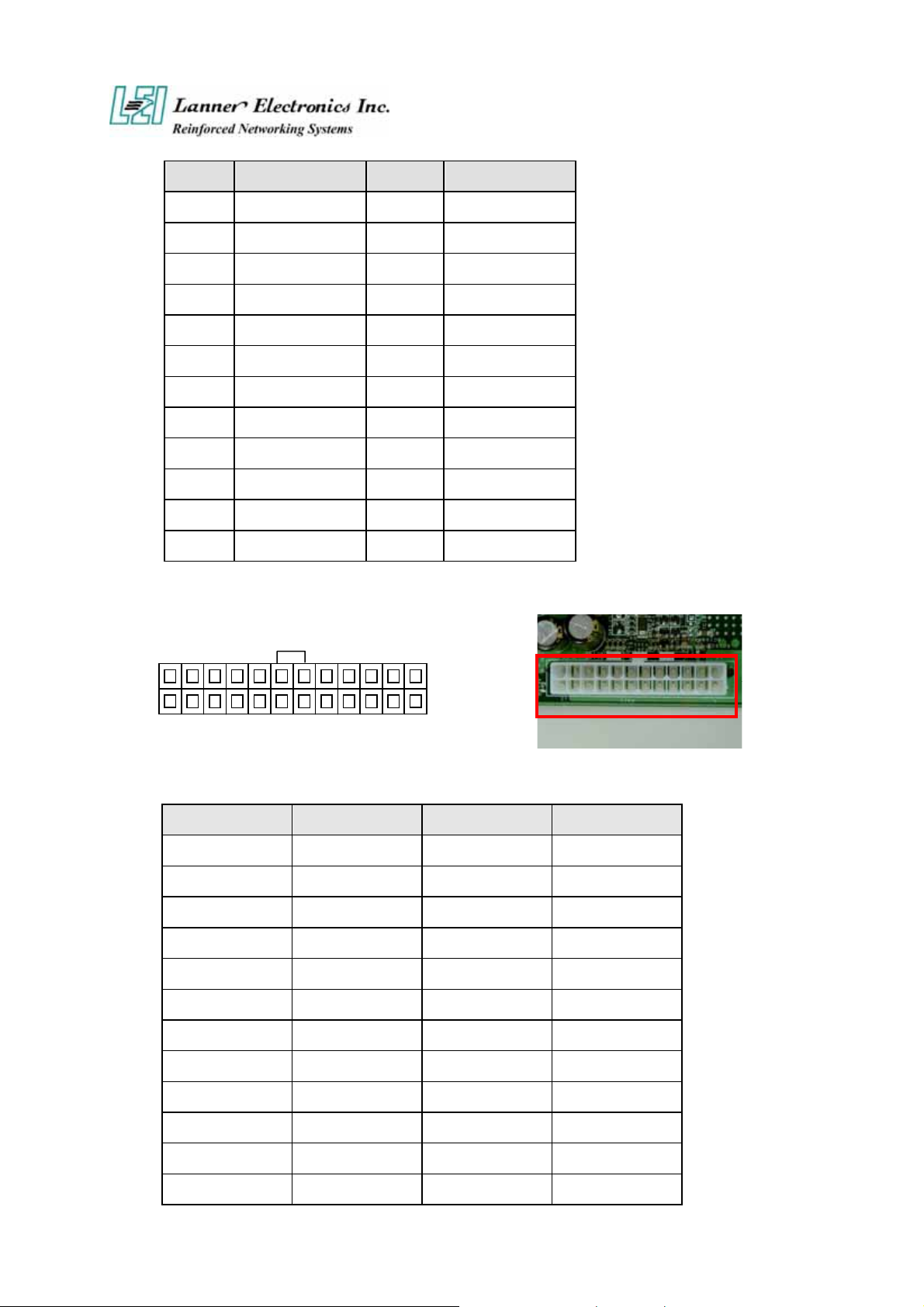
PIN NO. DESCRIPTION PIN NO. DESCRIPTION
1 +3.3V 13 +3.3V
2 +3.3V 14 -12V
3 Ground 15 Ground
4 +5V 16 PSON-
5 Ground 17 Ground
6 +5V 18 Ground
7 Ground 19 Ground
8 Power Good 20 NC
9 Stand-By 5V 21 +5V
10 +12V 22 +5V
11 +12V 23 +5V
12 +3.3V 24 Ground
PSC1
PCIB1:124 Pin Mini PCI Socket
Pin No. Description Pin No. Description
1 TIP 2 RING
3 8PMJ-3 4 8PMJ-1
5 8PMJ-6 6 8PMJ-2
7 8PMJ-7 8 8PMJ-4
9 8PMJ-8 10 8PMJ-5
11 LED1_GRNP 12 LED2_YELP
13 LED1_GRNN 14 LED2_YELP
15 CHSGND 16 RESERVED
17 INT-B 18 +5V
19 +3.3V 20 INT-A
21 RESERVED 22 RESERVED
23 GROUND 24 3.3VAUX
10
 Loading...