

Lanner electronic FW-6420 User Manual

FW-6420 Series
Mini Desktop VIA Eden low-power
Network Security Appliance
User’s Manual

Copyright and Disclaimers
© Copyright 2004 - Lanner Electronics Inc.
All Rights Reserved
The contents in this publication have been thoroughly checked and considered accurate. The
publisher and manufacturer of this product, Lanner Electronics, is not responsible for any
violation of patents or other rights of third parties resulting from its use. Neither does Lanner
Electronics assume any responsibility for any inaccuracies contained in this manual, nor make
any commitment to keep the information in this document up-to-date.
Lanner reserves the right to make improvements to this document and/or this product at any
given time without notice.
No part of this document may be reproduced, stored in a retrieval system, or transmitted in any
form or by any means (electronic, mechanical, photocopying, recording, or otherwise, without
the formal consent from Lanner.
Trademark Acknowledgments
All products and/or brand names stated in this publication are the trademarks of their rightful
and associated companies.
Radio Frequency Emissions Notice
This equipment has been tested and found to comply with the digital device limits pursuant to
Part 15 of the FCC Rules. These limits are designed to provide reasonable protection against
harmful interference when operate in a commercial environment. This equipment generates,
uses, and can radiate radio frequency energy and, if not installed and used in accordance with
the instruction manual, may cause harmful interference to radio communications. Operation of
this equipment in a residential area may cause harmful interference, in which case the user will
be required to correct the interference at his expense.
ii

Safety Instructions
The following information relates to the safety of installation and maintenance personnel. Read
all instructions before attempting to unpack, install or operate this equipment, especially before
connecting the power adapter.
Please keep the following in mind as you unpack and install this equipment:
Always follow basic safety precautions to reduce the risk of fire, electrical shock and
injury to persons.
Do not apply power into FW-6420 before installation or when disconnecting this
product from its original system setup.
Use only the specified power adapter (output voltage: 12VDC/5A) and make sure the
power adaptor’s plug matches your electrical wall outlet.
To prevent fire or shock hazard, do not expose the unit to rain, moisture or install this
product near water.
Locate a safe and dry location to place this product. Keep it away from wet
surfaces/surroundings.
Never push an object of any kind into this product through openings or empty slots, as
you may damage parts.
Do not attach the power supply cabling to building surfaces. Do not allow anything to
rest on the power cabling or allow it to be abused by persons walking on it.
Distance your working area from moist floors, ungrounded power extension cables, and
unavailable safety grounds.
Avoid installation of this product during a lighting storm.
Damages caused by electrostatic discharge may result in total or intermittent system
failures. To minimize the possibility of ESD damage, an anti-static strap is highly
recommended.
When cleaning or servicing this unit, avoid using highly toxic or aerosol cleaners. Use a
clean damp cloth when wiping its surfaces.
Do not place this device in a tight and sealed location. Place the unit where it can access
sufficient airflow to its vent holes (openings along its sides). Never block or cover these
openings.
Do not disassemble this product on your own.
iii

Getting Technical Assistance
Should you encounter questions or problems with your FW-6420, Lanner Electronics is ready
to assist you within the guidelines of our product support programs. First, check the electronic
product documentation for assistance. If you still cannot find the solution to your problem,
contact Lanner sales team with the following information handy:
FW-6420 model name
Part number
Local network configuration details
The abnormal behavior and/or error messages reported by your network system
Your questions, or a description of the problem you are experiencing
Call, fax, or e-mail Lanner Electronics for technical support.
Phone: 886-2-8692-6060
Fax: 886-2-8692-6101
E-mail: sales@lannerinc.com
About this Manual
This target audience of this manual includes users, administrators and technicians. This
publication is a useful reference when installing, configuring, operating and managing the
FW-6420. This breakdown and short descriptions of this manual’s contents are as follows:
Chapter 1 – Introduction provides an overview of the FW-6420 mini
desktop network security appliance, including its related features,
application usage and technical specifications list. The chapter also
guides users through the pre and post installation process by listing safety
tips plus an overall detailed description of the control board and system
and their vital components.
Chapter 2 – Introduce Hardware Installation
Chapter 3 – Award BIOS Setup
Appendix A –summarizes the specification of the power adapter
iv

Table of Contents
Copyright and Disclaimers....................................................................................................ii
Trademark Acknowledgments...............................................................................................ii
Radio Frequency Emissions Notice..................................................................... ii
Safety Instructions............................................................................................... iii
Getting Technical Assistance.............................................................................. iv
About this Manual................................................................................................ iv
Table of Contents................................................................................................ v
C h a p t e r 1.........................................................................................................................1
Getting Started 1
1.1 Introduction.................................................................................................. 1
1.1.1 Features...............................................................................................................................1
1.2 Technical Specifications.............................................................................. 2
1.3 Packing Contents........................................................................................ 3
1.4 EM-661 System Board................................................................................ 4
1.4.1 Mechanical Dimensions.......................................................................................................4
1.4.2 Board Layout........................................................................................................................5
1.4.3 Jumper Settings and I/O Connector.....................................................................................6
1.4.4 Connector Pin Assignments.................................................................................................6
CMOS1:Clear CMOS Data ............................................................................... 6
PLRS1:Power LED,HD LED, Reset, Speaker Connector(11 Pin 2.54mm) ...... 6
FAN1 : 3 Pin FAN Connector........................................................................... 7
LANA1~4: Type 1 ( RJ-45 ).............................................................................. 7
PRJK1 : 3 Pin Power Input Jack........................................................................ 7
COMA1: RS-232 Serial Port #1 Connector (D-Sub) ....................................... 7
VGB1 : External VGA Connector (2X6 Header 2.54mm )............................... 7
PKMB1: PS/2 Keyboard & Mouse Connector (2x4 Header 2.54mm )............. 8
USBB1: Dual Connector ................................................................................... 8
IDEA1 : IDE Interface Connector ( 44Pin 2.0mm Pitch Header ) .................... 9
CF1: Compact Flash Connector ...................................................................... 10
LPTA1: Parallel Connector (26 Pin 2.00mm Pitch Header).............................11
PCIB1:124-pin Mini PCI Sockets ................................................................... 12
RSW1: 4-pin Software Reset Switch............................................................... 13
1.5 FW-6420 Mini Desktop Firewall Mechanisms............................................. 14
1.5.1 Mechanical Dimensions.......................................................................................................14
1.5.2 Face Panel...........................................................................................................................14
1.5.3 Rear View.............................................................................................................................16
C h a p t e r 2.......................................................................................................................17
FW-6420 Hardware Installation Guide..............................................................................17
2.1 Hardware Installation Guide........................................................................ 17
Chapter 3..............................................................................................................................20
Award BIOS Setup..............................................................................................................20
3.1 Running AWARD BIOS................................................................................. 20
3.2 CMOS Setup Utility ....................................................................................... 21
3.3 Standard CMOS Setup.................................................................................. 23
3.4 Advanced BIOS Features Setup ................................................................... 26
3.5 Advanced Chipset Setup............................................................................... 27
3.6 Integrated Peripherals Setup......................................................................... 29
3.7 Power Management Setup........................................................................... 30
v

3.8 PCI Plug and Play Setup............................................................................... 32
3.9 PC Health Status........................................................................................... 34
3.10 Load Optimal Defaults................................................................................. 35
3.11 Supervisor / User Password........................................................................ 36
3.12 Save & Exit Setup ....................................................................................... 37
3.13 Exit Without Saving ..................................................................................... 37
Appendix A...........................................................................................................................38
A p p e n d i x B...................................................................................................................39
Console Redirection ............................................................................................................39
Terms and Conditions........................................................................................................................ 40
Warranty Policy 40
RMA Service 40
vi
1.1 Introduction
C h a p t e r 1
Getting Started
Figure 1 – FW-6420 Outlook
Designed for the Small and Medium-sized Businesses(SMB) in mind, the FW-6420 is a
powerful, yet flexible mini-desktop solution for the SMB network security market. The
FW-6420 is embedded with a VIA Eden low power CPU, running at 400MHz or 1GHz. It is
also equipped with four Ethernet ports each with its own Realtek RTL8139C+ and supports
Compact Flash Type II, PCI and Mini PCI. The FW-6420 is the ideal solution for developers,
who require a speedy Time-to-Market network security product for the fast growing network
security market. With this network security device you can provide a number of networking
security functions that werer previously only available for the larger Enterprises, such as
Virtual Private Network (VPN), Firewall, Multi-Homing and many more.
1.1.1 Features
Listed below are the key features of FW-6420.
Supports 2.5” HDD
Supports VIA Eden ESP 400MHz or 1GHz processor
Supports one DDR DIMM socket (184-pin);up to 1 GB
Supports four 10/100Mbps Ethernet ports, each with an independent Realtek
RTL8139C+ chipset
Supports Compact Flash, Serial(RS-232), PCI and Mini PCI.
One software reset Button
Mini desktop network security solution
Suitable Network applications; Virtual Private Network(VPN), Firewall, IDS,
Multi-Homing, Residential Gateway, Router and many more…
1
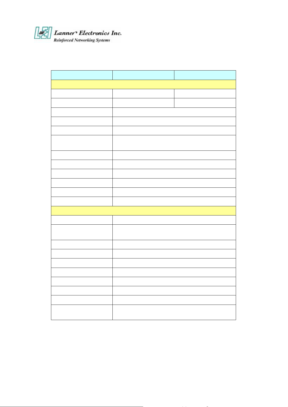
1.2 Technical Specifications
Model Name FW-6420B FW-6420E
SBC
SBC
CPU
Chipset
BIOS
Memory
Network interface
SSD
I/O Interface
Expansion Slot
Reset
RTC
Power
Form Factor
LED Indicator
Operating Temperature
Storage Temperature
EM-661B EM-661E
VIA Eden 400 MHz VIA Eden 1GHz
VIA CLE266 VT8623/VT8235
Award BIOS
One 184 pin DDR DIMM, up to 1GB
Four Realtek RTL8139C+, support 10/100Mbps
Ethernet with four external RJ-45 Connectors
One CompactFlash TypeII Socket
One DB-9 RS-232 connector
One PCI and One Mini-PCI slot
One reset button for software reset
Internal RTC with LI battery
One power jack 12V, 5A, 2.5mm
Mechanical/ Environmental
Slim destop
1*Power, 1*Status, 4*LAN speed 10/100Mbps,
4*LAN link/Active
o
0
C – 40 oC
o
-20
C – 70 oC
Humidity
Chassis Material
Dimension(H x W x D)
Net Weight
Certification
Software support
5% - 95% RH, non-condersing
Steel
50 x 330 x 161.7 mm
2 KGS
CE, FCC CLASS B
Linux 6.5 and above, Windows
95/98/2000/2003/ME/XP
2

1.3 Packing Contents
Carefully unpack your package and make sure that you have the following items.
FW-6420 Network security Platform
Console cable
1.8 meters long cross-over Ethernet cable
1.8 meters long straight-through Ethernet cable
Face panel name plate label
Power adapter
Power cable
Drivers and User’s Manual CD
If you find anything missing or damaged, promptly contact your dealer for assistance.
3
1.4 EM-661 System Board
EM-661 is the system board bundled with the FW-6420 Network security platform. The
succeeding sections list all EM-661 related jumper settings and connector pin assignments.
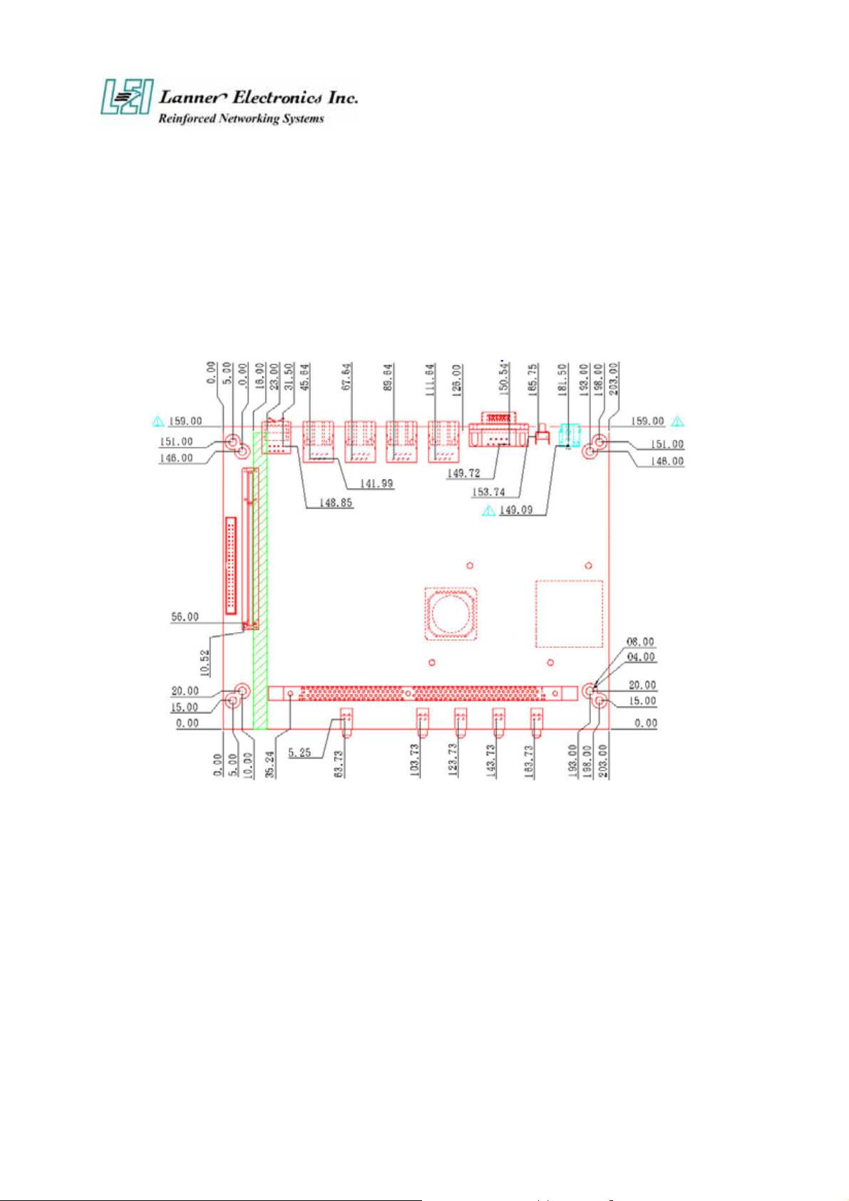
1.4.1 Mechanical Dimensions
Figure 2 – EM-661 Control Board Dimensions (units in mm)
4

1.4.2 Board Layout
Figure 3 – EM-661 Jumpers and Connectors
5
1.4.3 Jumper Settings and I/O Connector
The onboard jumper settings and I/O connector of EM-661 are custom-tailored to fit the
FW-6420 functionality. Changing the jumper settings may result in system malfunction or
unforeseen damages.
Jumper Settings and I/O Connector Summary for EM-661
JUMPER FUNCTION
CMOS1 Clear CMOS Data
PLRS1 Power LED,HD LED, Reset, Speaker Connector(11 Pin 2.54mm)
FAN1 3 Pin Fan Connector
LAN1-4 LAN Connector
PRJK1 3 Pin Power Input Jack
COMA1 RS-232 Serial Port #1 Connector ( D-Sub )
PKMB1 PS/2 Keyboard & Mouse Connector
VGAB1 External VGA Connector ( Header )
LPTA1 Parallel Connector
USBB1 Dual USB Connector
CF1 Compact Flash Connector
IDEB1 IDE Interface Connector
PCIB1 124 Pin Mini PCI Socket
1.4.4 Connector Pin Assignments
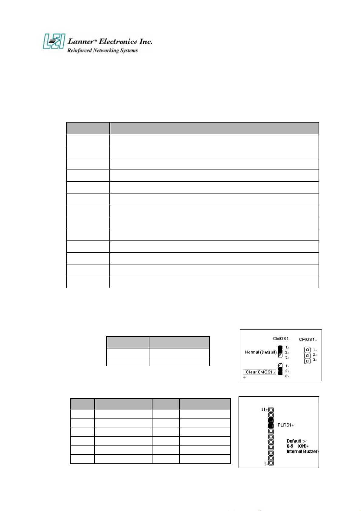
CMOS1:Clear CMOS Data
COM1 Description
1-2 Normal (Default)
2-3 Clear CMOS
PLRS1:Power LED,HD LED, Reset, Speaker Connector(11 Pin 2.54mm)
Pin No. Description Pin No. Description
1 Power LED + 2 Power LED -
3 Ground 4 HDD LED +
5 HDD LED - 6 RESET SW +
7 RESET SW – (GND) 8 External Speaker -
9 Internal Buzzer - 10 NC
11 External Speaker +
6
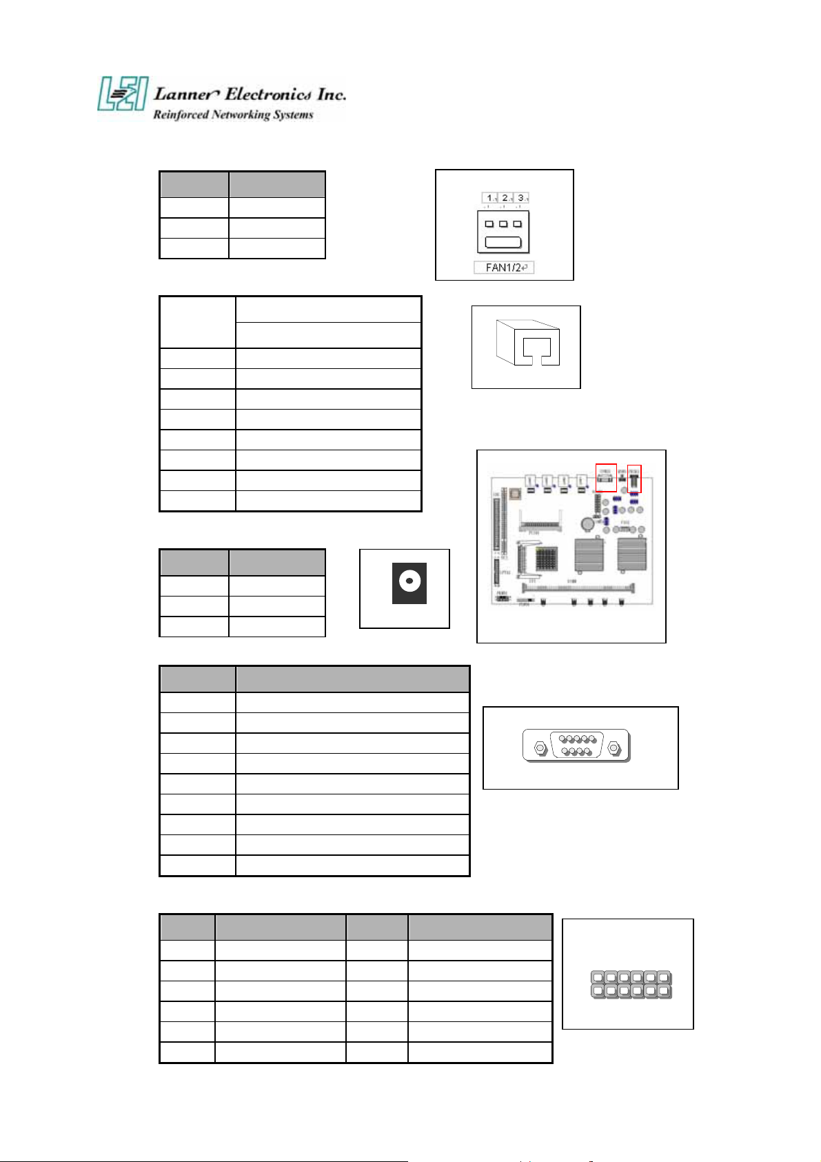
FAN1 : 3 Pin FAN Connector
Pin No. Description
1 Ground
2 +12V
3 FA N Status
LANA1~4: Type 1 ( RJ-45 )
Pin No.
1 TX+
2 TX-
3 RX+
4 T45
5 T45
6 RX-
7 T78
8 T78
Description
Fast E-Net
PRJK1 : 3 Pin Power Input Jack
Pin No. Description
1 Ground
2 Ground
3 +12V
PRJK1
COMA1: RS-232 Serial Port #1 Connector (D-Sub)
Pin No. Description
1 Data Carrier Detect (DCDA #)
2 Receive Data (RXDA)
3 Transmit Data (TXDA)
4 Data Terminal Ready (DTRA #)
5 Ground (GND)
6 Data Set Ready (DSRA #)
7 Request To Send (RTSA #)
8 Clear To Send (CTSA #)
9 Ring Indicator (RIA #)
LANA1
15
COMA1
9 6
VGB1 : External VGA Connector (2X6 Header 2.54mm )
Pin No. Description Pin No. Description
1 R 2 Ground
3 G 4 Ground
5 B 6 Ground
7 H-SYNC 8 Ground
9 V-SYNC 10 Ground
11 Detect-display Data 12 Detect-display CLOCK
7
1
VGB1
12 2
11
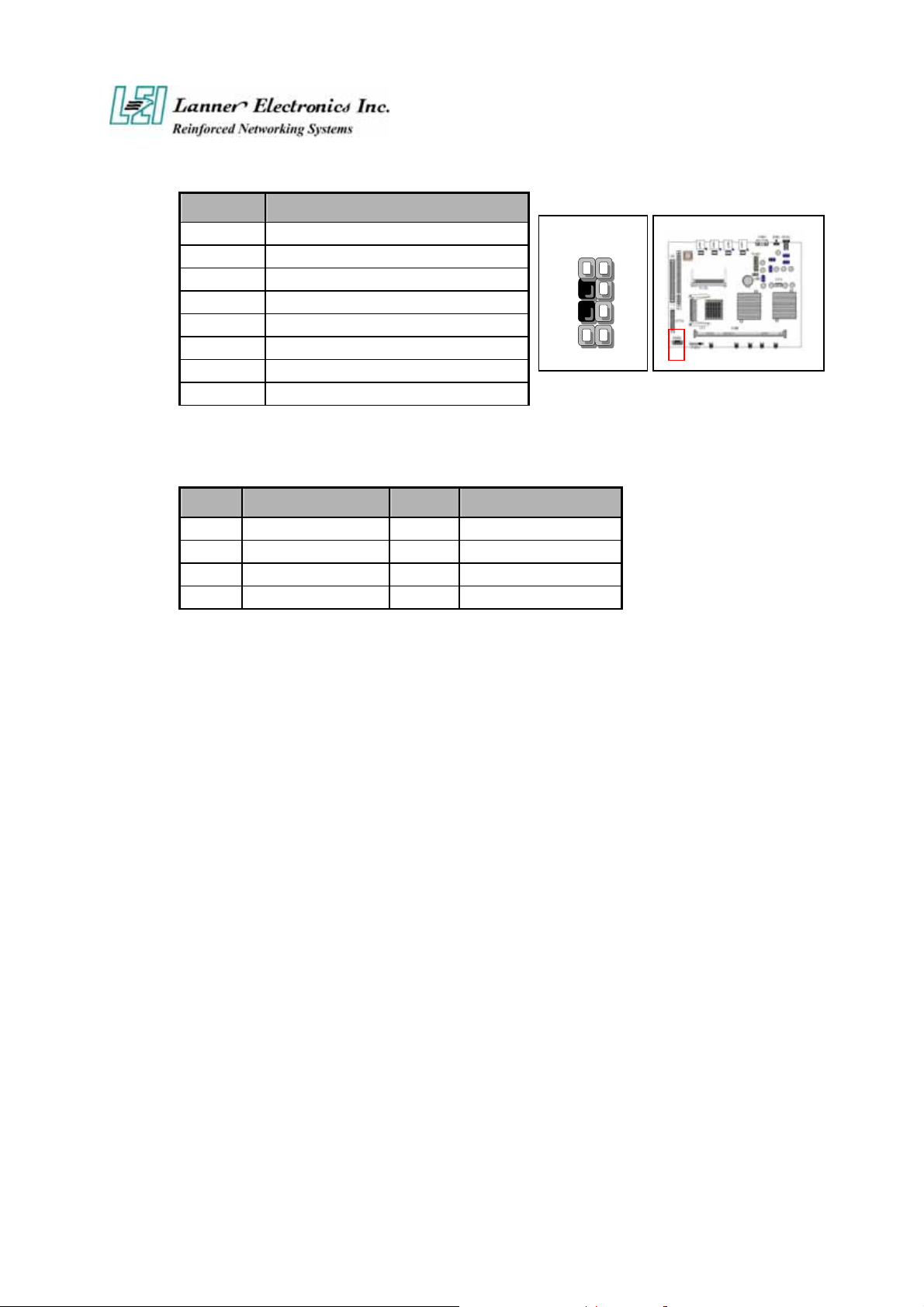
PKMB1: PS/2 Keyboard & Mouse Connector (2x4 Header 2.54mm )
Pin No. Description
1 KBCLK)
2 Ground
3 NC
4 KBDATA
5 NC
6 MSDATA
7 MSCLK
8 VCC
USBB1: Dual Connector
Pin No. Description Pin No. Description
1 USB_VCC 2 USBD0-
3 USBD0+ 4 Ground
5 USB_VCC 6 USBD1-
7 USBD1+ 8 Ground
1
3
5
7
2
4
6
8
8
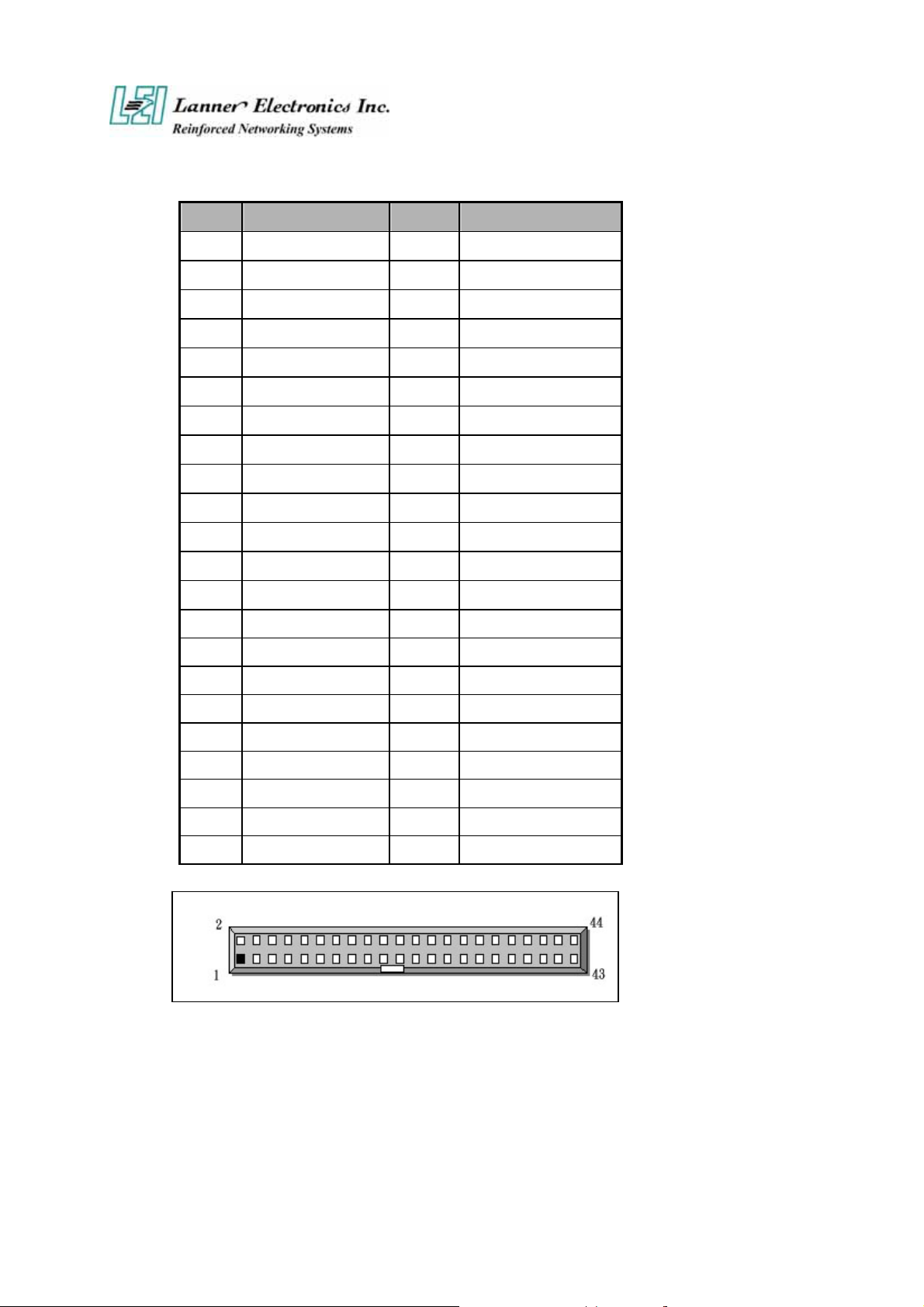
IDEA1 : IDE Interface Connector ( 44Pin 2.0mm Pitch Header )
Pin No. Description Pin No. Description
1
3
5
7
9
11
13
15
17
19
21
23
25
27
29
31
33
35
37
39
41
43
Reset #
Data 7
Data 6
Data 5
Data 4
Data 3
Data 2
Data 1
Data 0
Ground
DMA REQ#
IOW #
IOR #
IOCHRDY
DMA ACK #
Interrupt
SA 1
SA 0
HDC CS 0#
HDD Active
VCC
Ground
2
4
6
8
10
12
14
16
18
20
22
24
26
28
30
32
34
36
38
40
42
44
Ground
Data 8
Data 9
Data 10
Data 11
Data 12
Data 13
Data 14
Data 15
NC
Ground
Ground
Ground
Ground
Ground
NC
NC
SA 2
HDC CS 1#
Ground
VCC
NC
9
 Loading...