

Page 1

V6S
User Manual
Version: 1.0
Date of Release: 2019-10-08
Vehicle Computing
1
Page 2
V6S User Manual
Resources
URL
Lanner
http://www.lannerinc.com
Product Resource
http://www.lannerinc.com/download-center
RMA
http://eRMA.lannerinc.com
The icons are used in the manual to serve as an indication of interest topics or important messages. Below
is a description of these icons:
Note: This mark indicates that there is a note of interest and is something that you should pay
special attention to while using the product.
Warning: This mark indicates that there is a caution or warning and it is something that could
damage your property or product.
The listed websites are links to the on-line product information and technical support.
This document is copyrighted © 2019. All rights are reserved. The original manufacturer reserves the right
to make improvements to the products described in this manual at any time without notice.
No part of this manual may be reproduced, copied, translated or transmitted in any form or by any means
without the prior written permission of the original manufacturer. Information provided in this manual is
intended to be accurate and reliable. However, the original manufacturer assumes no responsibility for its
use, nor for any infringements upon the rights of third parties that may result from such use.
Intel® , Intel® Core™ are trademarks or registered trademarks of Intel Corporation or its subsidiaries in the
U.S. and/or other countries.
Microsoft Windows and MS-DOS are registered trademarks of Microsoft Corp.
All other product names or trademarks are properties of their respective owners.
2
Page 3
This product has passed the CE test for environmental specifications. Test conditions for passing included
the equipment being operated within an industrial enclosure. In order to protect the product from being
damaged by ESD (Electrostatic Discharge) and EMI leakage, we strongly recommend the use of
CE-compliant industrial enclosure products.
This equipment has been tested and found to comply with the limits for a Class A digital device, pursuant to
Part 15 of the FCC Rules. These limits are designed to provide reasonable protection against harmful
interference when the equipment is operated in a commercial environment. This equipment generates,
uses and can radiate radio frequency energy and, if not installed and used in accordance with the
instruction manual, may cause harmful interference to radio communications. The operation of this
equipment in a residential area is likely to cause harmful interference in which case the user will be required
to correct the interference at his own expense.
This equipment has been tested and found to comply with the limits for a Class A digital device, pursuant to
Part 15 of the FCC Rules. These limits are designed to provide reasonable protection against harmful
interference when the equipment is operated in a commercial environment. This equipment generates,
uses, and can radiate radio frequency energy and, if not installed and used in accordance with the
instruction manual, may cause harmful interference to radio communications. The operation of this
equipment in a residential area is likely to cause harmful interference in which case users will be required to
correct the interference at their own expense.
Follow these guidelines to ensure general safety:
Keep the chassis area clear and dust-free during and after installation.
Do not wear loose clothing or jewelry that could get caught in the chassis. Fasten your tie or scarf and
roll up your sleeves.
Wear safety glasses if you are working under any conditions that might be hazardous to your eyes.
Do not perform any action that creates a potential hazard to people or makes the equipment unsafe.
Disconnect all power by turning off the power and unplugging the power cord before installing or
removing a chassis or working near power supplies
Do not work alone if potentially hazardous conditions exist.
Never assume that power is disconnected from a circuit; always check the circuit.
3
Page 4
V6S User Manual
Suivez ces consignes pour assurer la sécurité générale :
Laissez la zone du châssis propre et sans poussière pendant et après l’installation.
Ne portez pas de vêtements amples ou de bijoux qui pourraient être pris dans le châssis. Attachez votre
cravate ou écharpe et remontez vos manches.
Portez des lunettes de sécurité pour protéger vos yeux.
N’effectuez aucune action qui pourrait créer un danger pour d’autres ou rendre l’équipement
dangereux.
Coupez complètement l’alimentation en éteignant l’alimentation et en débranchant le cordon
d’alimentation avant d’installer ou de retirer un châssis ou de travailler à proximité de sources
d’alimentation.
Ne travaillez pas seul si des conditions dangereuses sont présentes.
Ne considérez jamais que l’alimentation est coupée d’un circuit, vérifiez toujours le circuit. Cet appareil
génère, utilise et émet une énergie radiofréquence et, s’il n’est pas installé et utilisé conformément aux
instructions des fournisseurs de composants sans fil, il risque de provoquer des interférences dans les
communications radio.
There is risk of Explosion if Battery is replaced by an incorrect type.
Dispose of used batteries according to the instructions.
Installation only by a skilled person who knows all Installation and Device Specifications which are to be
applied.
Do not carry the handle of power supplies when moving to another place.
Please conform to your local laws and regulations regarding safe disposal of lithium BATTERY.
Disposal of a battery into fire or a hot oven, or mechanically crushing or cutting of a battery can result in
an explosion.
Leaving a battery in an extremely high temperature surrounding environment can result in an explosion
or the leakage of flammable liquid or gas.
A battery subjected to extremely low air pressure that may result in an explosion or the leakage of
flammable liquid or gas.
Risque d’explosion si la pile est remplacée par une autre d’un mauvais type.
Jetez les piles usagées conformément aux instructions.
L’installation doit être effectuée par un électricien formé ou une personne formée à l’électricité
connaissant toutes les spécifications d’installation et d’appareil du produit.
Ne transportez pas l’unité en la tenant par le câble d’alimentation lorsque vous déplacez l’appareil.
4
Page 5

Electrical equipment generates heat. Ambient air temperature may not be adequate to cool equipment
to acceptable operating temperatures without adequate circulation. Be sure that the room in which you
choose to operate your system has adequate air circulation.
Ensure that the chassis cover is secure. The chassis design allows cooling air to circulate effectively. An
open chassis permits air leaks, which may interrupt and redirect the flow of cooling air from internal
components.
Electrostatic discharge (ESD) can damage equipment and impair electrical circuitry. ESD damage occurs
when electronic components are improperly handled and can result in complete or intermittent failures.
Be sure to follow ESD-prevention procedures when removing and replacing components to avoid these
problems.
Wear an ESD-preventive wrist strap, ensuring that it makes good skin contact. If no wrist strap is
available, ground yourself by touching the metal part of the chassis.
Periodically check the resistance value of the antistatic strap, which should be between 1 and 10
megohms (Mohms).
L’équipement électrique génère de la chaleur. La température ambiante peut ne pas être adéquate pour
refroidir l’équipement à une température de fonctionnement acceptable sans circulation adaptée.
Vérifiez que votre site propose une circulation d’air adéquate.
Vérifiez que le couvercle du châssis est bien fixé. La conception du châssis permet à l’air de
refroidissement de bien circuler. Un châssis ouvert laisse l’air s’échapper, ce qui peut interrompre et
rediriger le flux d’air frais destiné aux composants internes.
Les décharges électrostatiques (ESD) peuvent endommager l’équipement et gêner les circuits
électriques. Des dégâts d’ESD surviennent lorsque des composants électroniques sont mal manipulés et
peuvent causer des pannes totales ou intermittentes. Suivez les procédures de prévention d’ESD lors du
retrait et du remplacement de composants.
Portez un bracelet anti-ESD et veillez à ce qu’il soit bien au contact de la peau. Si aucun bracelet n’est
disponible, reliez votre corps à la terre en touchant la partie métallique du châssis.
Vérifiez régulièrement la valeur de résistance du bracelet antistatique, qui doit être comprise entre 1 et
10 mégohms (Mohms).
Mounting Installation Precaution
Environment:
Do not install and/or operate this unit in any place that flammable objects are stored or used in.
If installed in a closed or multi-unit rack assembly, the operating ambient temperature of the rack
environment may be greater than room ambient. Therefore, consideration should be given to installing
the equipment in an environment compatible with the maximum ambient temperature (Tma) specified
5
Page 6

V6S User Manual
by the manufacturer.
Installation of the equipment (especially in a rack) should consider the ventilation of the system’s intake
(for taking chilled air) and exhaust (for emitting hot air) openings so that the amount of airflow required
for safe operation of the equipment is not compromised.
To avoid a hazardous load condition, be sure the mechanical loading is even when mounting.
Consideration should be given to the connection of the equipment to the supply circuit and the effect
that overloading of the circuits might have on over-current protection and supply wiring. Appropriate
consideration of equipment nameplate ratings should be used when addressing this concern.
Reliable earthing should be maintained. Particular attention should be given to supply connections
other than direct connections to the branch circuit (e.g., use of power strips).
Installation & Operation:
The installation of this product must be performed by trained specialists; otherwise, a non-specialist
might create the risk of the system’s falling to the ground or other damages.
Lanner Electronics Inc. shall not be held liable for any losses resulting from insufficient strength for
supporting the system or use of inappropriate installation components.
Before turning on the device, ground the grounding cable of the equipment. Proper grounding
(grounding) is very important to protect the equipment against the harmful effects of external noise and to
reduce the risk of electrocution in the event of a lightning strike. To uninstall the equipment, disconnect
the ground wire after turning off the power. A ground wire is required and the part connecting the
conductor must be greater than 4 mm2 or 10 AWG.
Avant d’allumer l’appareil, reliez le câble de mise à la terre de l’équipement à la terre.
Une bonne mise à la terre (connexion à la terre) est très importante pour protéger l’équipement contre
les effets néfastes du bruit externe et réduire les risques d’électrocution en cas de foudre.
Pour désinstaller l’équipement, débranchez le câble de mise à la terre après avoir éteint l’appareil.
Un câble de mise à la terre est requis et la zone reliant les sections du conducteur doit faire plus de 4
mm2 ou 10 AWG.
6
Page 7
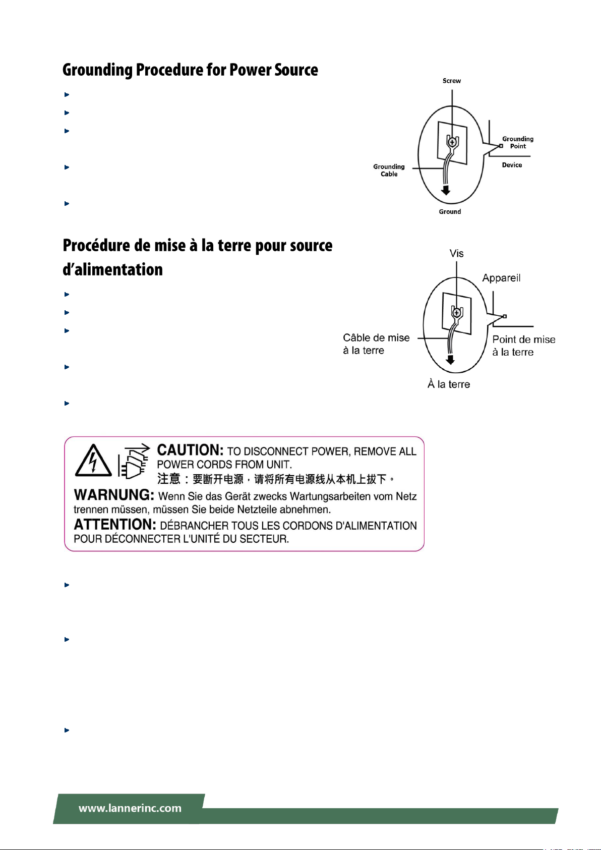
Loosen the screw of the earthing point.
Connect the grounding cable to the ground.
The protection device for the power source must provide 30 A
current.
This protection device must be connected to the power source
before power.
The cable hould 16 AWG
Desserrez la vis du terminal de mise à la terre.
Branchez le câble de mise à la terre à la terre.
L’appareil de protection pour la source d’alimentation
doit fournir 30 A de courant.
Cet appareil de protection doit être branché à la source
d’alimentation avant l’alimentation.
Le câble doit 16 AWG
This equipment must be grounded.
Cet équipement doit être mis à la terre.
Suitable for installation in Information Technology Rooms in accordance with Article 645 of the National
Electrical Code and NFPA 75.
Peut être installé dans des salles de matériel de traitement de l'information conformément à l'article 645
du National Electrical Code et à la NFPA 75.
The machine can only be used in a restricted access location and has installation instructions by a skilled
person.
Les matériels sont destinés à être installés dans des EMPLACEMENTS À ACCÈS RESTREINT.
7
Page 8

V6S User Manual
Package Content ......................................................................................................................... 10
Ordering Information ................................................................................................................. 11
System Specifications ................................................................................................................. 11
Front Panel ................................................................................................................................. 13
Rear Panel ................................................................................................................................. 14
Block Diagram ............................................................................................................................. 15
Internal Jumpers & Connectors .................................................................................................. 17
Installing the Disk Drive .............................................................................................................. 22
Installing 4G Module .................................................................................................................. 24
Installing SIM Cards .................................................................................................................... 25
Enter BIOS Setup ........................................................................................................................ 26
Main ............................................................................................................................................ 27
Advanced .................................................................................................................................... 28
Chipset ........................................................................................................................................ 55
Security ....................................................................................................................................... 70
Boot ............................................................................................................................................ 73
Save and Exit ............................................................................................................................... 74
8
Page 9

Connecting the Devices .............................................................................................................. 76
Power States Cycle ..................................................................................................................... 77
Using the Ignition System Manager (ISM) .................................................................................. 78
Warranty Policy .......................................................................................................................... 79
RMA Service ................................................................................................................................ 79
RMA Service Request Form ........................................................................................................ 80
9
Page 10
V6S User Manual
V6S is the next-generation rugged, fanless vehicle surveillance NVR. It is designed for public transit video
surveillance, recording and analytics. V6S, being the robust vehicle surveillance NVR, can operate under
wide temperature range (-20~60°C), indicating its excellent reliability in a harsh environment.
V6S is powered by the 7th Generation 14 nm Intel® Core™ i7-7600U SoC (formerly Kaby Lake), offering
power-efficient performance and accelerated graphics performance for vehicle computing needs.
Designed for mobile surveillance, the new V6S series offers 1 x GbE RJ45 ports plus 10 x RJ-45 PoE ports for
IP camera connection, and two removable 2.5” HDD/SSD drive bays for the storage of recorded footages.
For wireless connectivity, V6S is internally built with 1 x full-sized Mini-PCIe with dual SIM card reader for
LTE/ WiFi, and 1x external M.2 3042 with dual SIM card readers, which allows 4G/LTE module to be
removable externally.
Intel® Core™ i7-7600U Dual Cores Processor
CE/FCC and E-mark certified, MIL-STD-810G anti-vibration & shock qualified. and E-mark certified
10x PoE and 1x GbE RJ45 ports
2x External Removable 2.5” HDD/SDD drive bays
1 x full-sized Mini-PCIe with dual SIM card reader for LTE/ WiFi, and 1x external M.2 3042 with dual SIM
card readers
2x COM, 2x USB 3.0, 2xUSB 2.0, 6x DI/DO, optional CAN bus, Audio, DVI, VGA
Wallmount kit
Fanless rugged design
Your package contains the following items:
1x V6S Vehicle Computer
1x Pack of Screws
1x DC to DC Adapter
Note: If you should find any components missing or damaged, please contact your dealer
immediately for assistance.
10
Page 11
Chapter 1: Product Overview
SKU No.
Description
V6S-A
Intel® Core i7-7600U in-vehicle Mobile NVR with 10x Intel GbE PoE and External 180w
DC power adapter for+9V~36Vdc input with Ignition
Processor System
CPU
Intel® Core™ i7-7600U 2.8GHz CPU onboard
Frequency
Up to 2.8 GHz
Core Number
Dual-core
Chipset
SoC
Fanless
Yes
Memory
Technology
2x DDR4 2133 SO-DIMM Socket
Max. Capacity
Up to 32 GB
Socket
2x 260-pin SODIMM
Graphic
Graphic Processor
Intel integrated HD Graphics 620
Audio
Codec
Realtek ALC886-GR HD codec
Interface
1x DB9 for MIC-in and Line-out
Ethernet
Controller
11x RJ45 with LED including: 1x Intel i210IT+ 1x Marvell
88E6390 POE Switch + 2x Intel i210IT POE port
Speed
10/100/1000 Mbps
PoE
10x IEEE 802.3af POE ports
Interface
RJ45
Storage
Type
SATA
Installation
2x Removable 2.5” drive bays (HDD/SSD is not included)
Type
mSATA
Installation
1x mSATA socket
I/O
Display
1x DVI-D, 1xVGA
LAN
1x RJ45 for GbE port, by Intel i210IT
CAN bus
1x 2x5 pin header for output connection to DB-9male external
connector; 1x Onboard connector to support optional CAN
Module
COM
2x RS-232/422/485 with RI/5V
1x for internal Ignition microcontroller programming
USB
2x USB 3.0 Type A, 2x USB 2.0 type A
Digital I/O
6x DI 5V or 12V TTL selectable
6x DO 12V TTL, Max. 100mA
2x IGN-DI of ignition control to MCU
1x 12V Output
SIM
2x SIM card sockets for internal mini-PCIe
GPS
1x Ublox NEO-M8N GPS module
G-Sensor
1x 3-axis accelerometer
Antenna
7x SMA antenna holes (includes GPS)
Expansion Interface
PCIe
1x removable M.2 socket (USB 3.0) interface for LTE with dual
SIM card readers
1 x full-sized Mini-PCIe (USB 3.0+ PCIe) with dual SIM card
reader (on edge) for LTE/ WiFi
Cooling
Processor
Passive CPU heatsink
System
Fanless design with corrugated aluminum
Power
Connector
3-pin terminal block (+,-,ignition)
Input
DC 9~36V (+ , - , ignition) supports ATX mode
support ignition delay on/ off control
11
Page 12

V6S User Manual
Environment
Operating Temperature
-20~60°C / -4~140°F (without battery backup)
Storage Temperature
20~70°C / -4~158°F
Relative Humidity
5%~95% @ 40°C / 104°F (Storage Level)
Mechanical
Dimension (W x H x D)
273.8 x 219 x 92.2 mm (without mounting)
308 x 219 x 120.8 mm (with mounting)
223 x 143.8 x 43.5 mm (LVP-936BAT01)
Weight
5.5 kg
Mounting
Wallmount kit
Driver Support
Microsoft Windows
Win10 IoT Enterprise
Linux
Redhat Enterprise 5, Fedora 14. Linux Kernel 2.6.18 or later
Certification
EMC
FCC/CE Class A, RoHS
Safety
E-13 include ISO-7637-2
Miscellaneous
Hardware
Fintek F81866AD-I integrated watchdog timer
Monitoring
1~255 level
Internal RTC with Li Battery
Yes
12
Page 13
Chapter 1: Product Overview
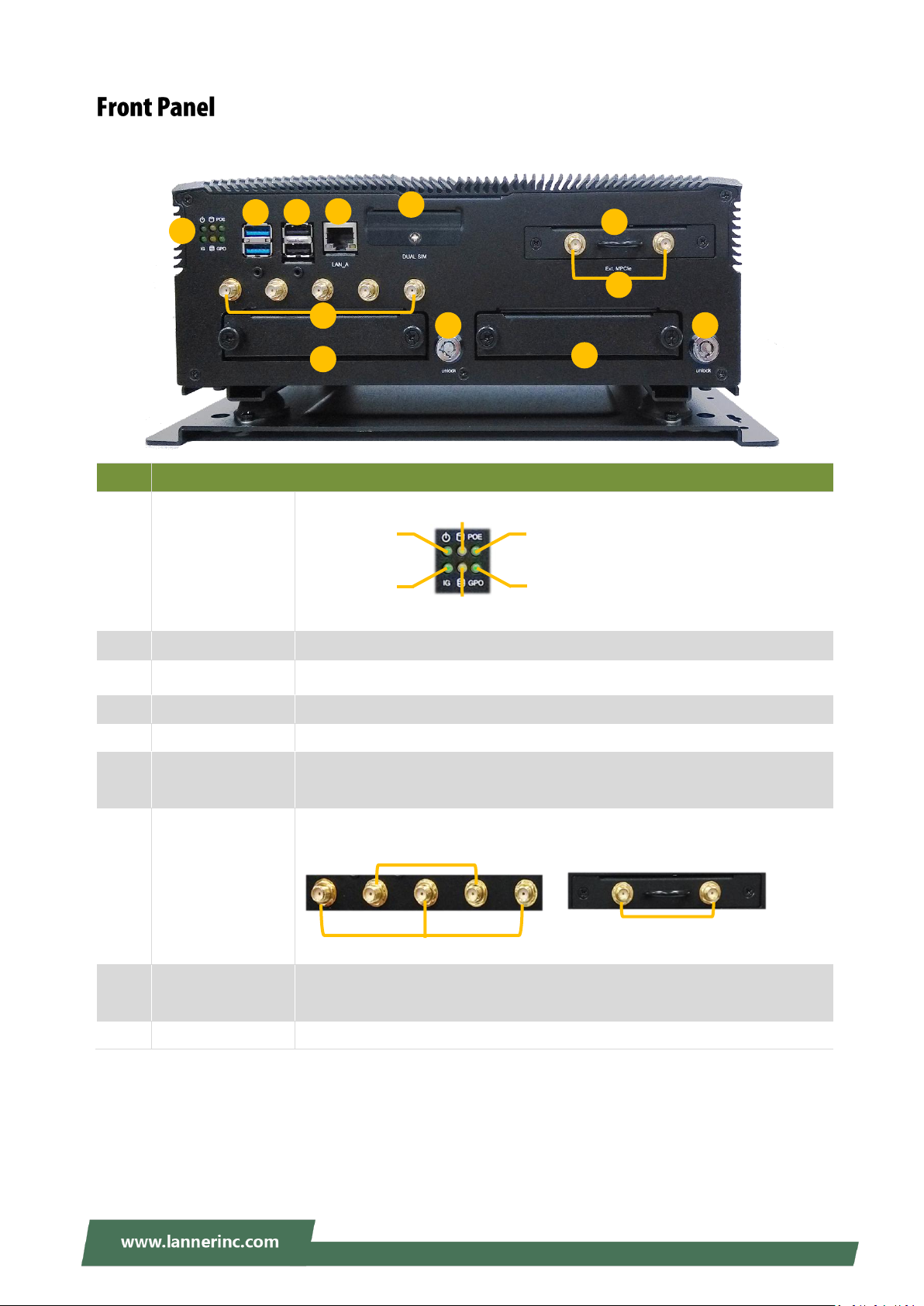
No.
Description
F1
System Status LED
Indicator
F2
USB 3.0 Port
2x USB 3.0 Type A
F3
USB 2.0 Port
2x USB 2.0 Type A
F4
GbE Port
1x RJ45 port with LED indicators
F5
Dual SIM Socket
For 2x SIM card
F6
External M.2 Slot
Removable M.2 Slot supporting Dual SIM and 2x Antenna Hole with dust
cover
F7
Antenna Port
7x Antenna Port
F8
Hard Disk Bay
2x SATA interface hard disk bays to support removable 2.5” HDD/SSD drives
with lock for each bay
F9
Key Lock
2x key locks for extra protection of the data on the hard disk
F9
F1
F3
F7
F4
F8
F9
F8
F2
F6
F5
F7
HDD 1
HDD 2
LTE Antenna
WiFi Antenna
LTE Antenna
HDD1 Status
HDD2 Status
PoE Status
GPO Status
System Power
Ignition Status
13
Page 14
V6S User Manual
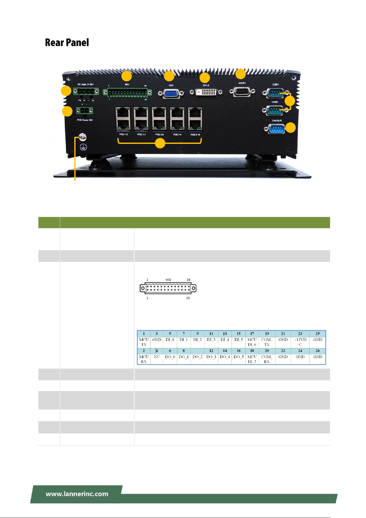
No.
Description
R1
DC Input
1x 3-pin terminal block for DC 9~36V external power source, GND and
Ignition
R2
PoE Power Input
1x 2-pin terminal block for +56VDC input for POE power.
R3
Multi-IO
1x 26-pin terminal block connector for GPIO and +12VDC output
6x DI ( 5V or 12V TTL selectable)
6x DO (12V TTL, Max. 100Ma)
2x DI to Ignition MCU as remote control ( 5V TTL)
1x 12V Output @Max. 1A
R4
VGA Port
1x VGA DB15 Connector
R5
DVI-D Port
1x DVI-D Connector
R6
Audio Port
1x Realtek ALC886-GR, supports external Audio I/O for
Line-in/Line-out with L/R-channels via 9-pin female connector
R7
COM Port
2x DB9 Male Connector for RS232/422/485
R8
CAN Bus Port
1x DB9 Male connector for CAN Bus
R9
PoE Port
10x PoE Port with LED indicators
R3
R6
R4
R1
R5
R8
R2
R9
R7
Grounding Point:
For safety measures to help prevent people from
accidentally coming in contact with electrical hazards.
PoE1
PoE2
PoE3
PoE4
PoE5
PoE6
PoE7
PoE8
PoE9
PoE10
14
Page 15
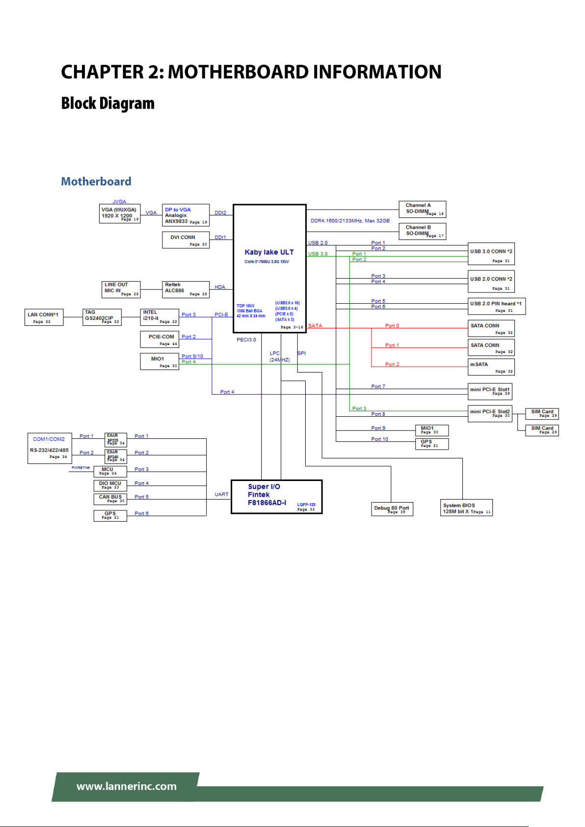
Chapter 2: Motherboard Information
The block diagram indicates how data flows among components on the motherboard. Please refer to the
following figure for your motherboard’s layout design.
15
Page 16
V6S User Manual
16
Page 17

Chapter 2: Motherboard Information
Pin No
Description
Pin No
Description
1
N.C
2
+3.3V3 N.C
4
GND 5 N.C
6
+1.5V7 N.C8 N.C9 GND
10
N.C
11
N.C
12
N.C
13
N.C
14
N.C
15
GND
16
N.C
KEY
17
N.C
18
GND
19
N.C
20
N.C
21
GND
22
N.C
23
SATA_RXp
24
+3.3V
25
SATA_RXn
26
GND
27
GND
28
+1.5V
29
GND
30
N.C
31
SATA_TXn
32
N.C
33
SATA_TXp
34
GND
35
GND
36
N.C
37
GND
38
N.C
39
+3.3V
40
GND
41
+3.3V
42
N.C
43
N.C
44
N.C
45
N.C
46
N.C
47
N.C
48
+1.5V
49
N.C
50
GND
51
N.C
52
+3.3V
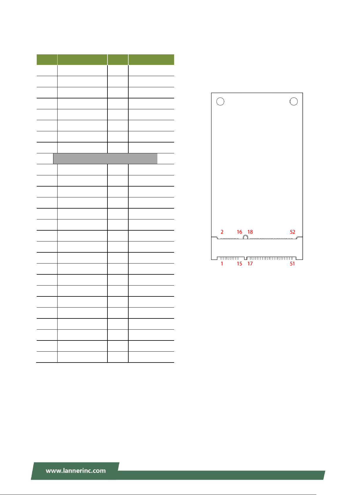
MSATA1
mSATA:
17
Page 18

V6S User Manual
Pin No
Description
Pin No
Description
1
N.C
2
+3.3V3 N.C
4
GND 5 N.C
6
+1.5V
7
CLKREQ#
8
N.C9 GND
10
N.C
11
REFCLK-
12
N.C
13
REFCLK+
14
N.C
15
GND
16
N.C
KEY
17
N.C
18
GND
19
N.C
20
N.C
21
GND
22
PERST#
23
PERn0
24
+3.3V
25
PERp0
26
GND
27
GND
28
+1.5V
29
GND
30
N.C
31
PETn0
32
N.C
33
PETp0
34
GND
35
GND
36
USB_D-
37
GND
38
USB_D+
39
+3.3V
40
GND
41
+3.3V
42
LED_WWAN#
43
GND
44
LED_WLAN#
45
N.C
46
N.C
47
N.C
48
+1.5V
49
N.C
50
GND
51
N.C
52
+3.3V
MPCIE1
mPCIE1 for wifi:
Supports Wi-Fi PCIe interface adapter
18
Page 19
Chapter 2: Motherboard Information
Pin No
Description
Pin No
Description
1
N.C
2
+3.3V3 N.C
4
GND 5 N.C
6
+1.5V
7
CLKREQ#
8
UIM_PWR
9
GND
10
UIM_DATA
11
N.C
12
UIM_CLK
13
N.C
14
UIM_RESET
15
GND
16
UIM_VPP
KEY
17
N.C
18
GND
19
N.C
20
N.C
21
GND
22
PERST#
23
USB3_RX-
24
+3.3V
25
USB3_RX+
26
GND
27
GND
28
+1.5V
29
GND
30
N.C
31
USB3_TX-
32
N.C
33
USB3_TX+
34
GND
35
GND
36
USB_D-
37
GND
38
USB_D+
39
+3.3V
40
GND
41
+3.3V
42
LED_WWAN#
43
GND
44
LED_WLAN#
45
N.C
46
N.C
47
N.C
48
+1.5V
49
N.C
50
GND
51
N.C
52
+3.3V
mPCIE2
mPCIE2 for 4G/LTE
Supports both 3G/4G and USB interface adapter
19
Page 20
V6S User Manual
Pin No
Description
Pin No
Description
1
SPI_HOLD
2
N.C
3
SPI_CS#
4
SPI_VCC
5
SPI_MISO
6
N.C7 N.C
8
SPI_CLK
9
GND
10
SPI_MOSI
Pin No
Description
Pin No
Description
1
LPC_CLK
2
LAD1
3
PLTRST
4
LAD0
5
LFRAME#
6
3.3V
7
LAD3
8
N.C9 LAD2
10
GND
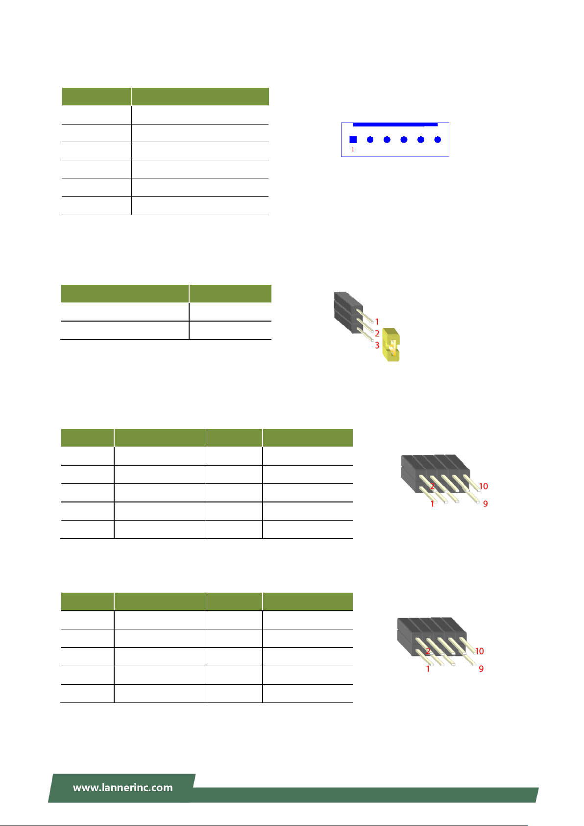
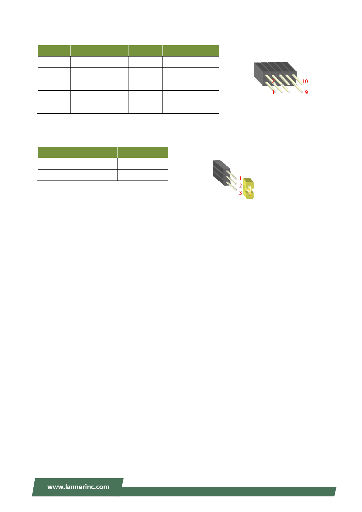
Pin No
Description
1
12V
2
GND
3
GND 4 5V
5
HDD_LED1
6
HDD_LED2
Description
JCMOS1
Normal (Default)
1-2
Clear CMOS
2-3
SATAPWR1
COMS1: Clear CMOS Use the jumper setting to clear CMOS
JSPI1:SPI Interface(debug only)
JLPC1:LPC Interface(debug only)
20
Page 21
Chapter 2: Motherboard Information
Pin No
Description
Pin No
Description
1
5V 2 5V
3
USB5-
4
USB6-
5
USB5+
6
USB6+
7
GND
8
GND
9
GND
10
GND
Description
J11
Normal (Default)
1-2
Program
2-3
JUSB1:USB2.0 Interface
J11:MCU State(Program Only)
21
Page 22
V6S User Manual
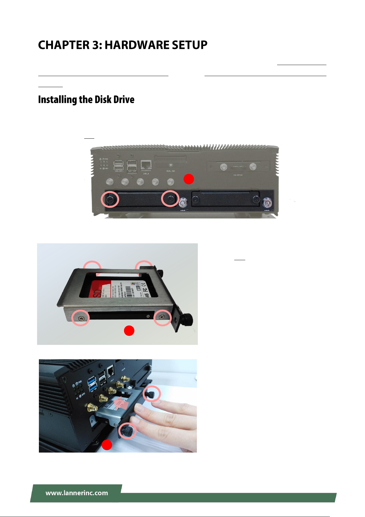
2. Install the disk onto the tray and secure
it with four provided disk screws. Make
sure the SATA connector faces outwards
as shown in the picture.
3. Insert the tray into the bay and fasten
the two screws that fix the tray on the
system.
HDD1
HDD2
1
SATA
Contacts
2
3
To reduce the risk of personal injury, electric shock, or damage to the unit, please remove all power
connections to completely shut down the device. Also, please wear ESD protection gloves when conducting
the steps in this chapter.
This system is built with two 2.5” HDD/SSD drive bays. The following will discuss disk drive installation
procedures based on their designs.
1. Unscrew the two screws that fix the tray on the system.
22
Page 23

Chapter 3: Hardware Setup
4. Lock the tray with the provided tray lock
key.
Lock
4
23
Page 24
V6S User Manual
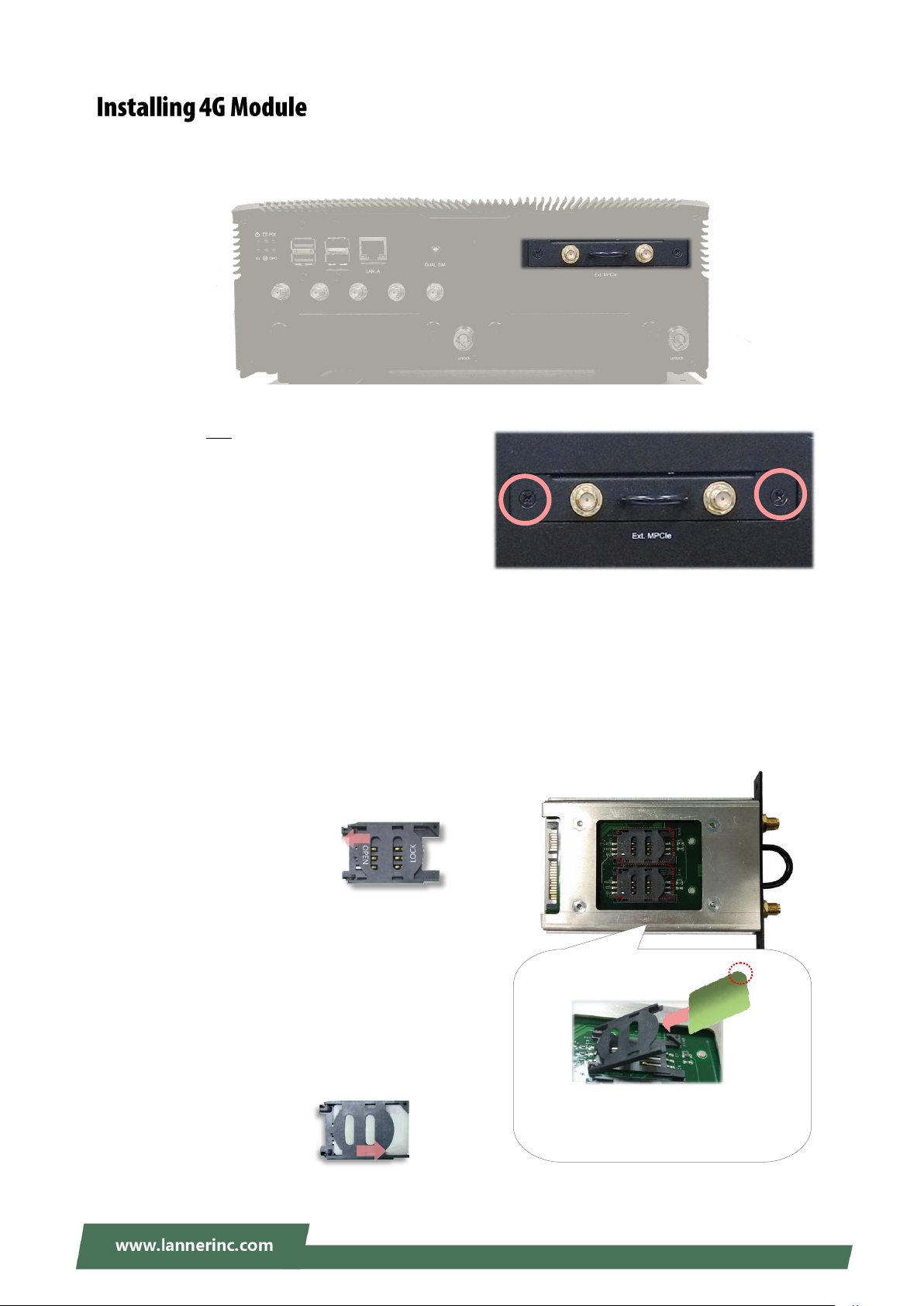
1. Loosen the two screws that secure the tray and
draw out the tray by its grip.
To Install the 4G module:
2. Locate the M.2 slot on the top side of this tray. Align the notch of the module with the socket key in the
slot, and insert it at 30 degrees into the socket until it is fully seated in the connector.
3. Push down on the module and secure it with the screw that comes with it.
4. Attach both inner antenna cables to this module.
To install the SIM cards:
5. Slide open the socket cover and lift the cover on its
hinges.
6. Insert the SIM card into the slot in the cover with
the gold contacts facing down.
7. Push down the cover to close, and the SIM card will
come in contact with the metal contacts in the
socket. Finally, Slide the socket cover to the Lock
position.
The angled corner of the card is
positioned as shown in this
picture.
LOCK
OPEN
This system comes with an external M.2 slot, supporting dual SIM design. The following will discuss the
installation of 4G module and SIM cards.
24
Page 25

Chapter 3: Hardware Setup
1. Loosen the screw that secures the cover onto the
system.
2. Push the SIM cards into the socket. Make sure the
angled corner of the card is positioned correctly as
shown in this picture.
To remove the card, simply push it to have it
bounce out automatically.
1
2
The externally accessible SIM card readers on edge allow you to easily install or remove SIM cards with its
push-in-bounce-out feature.
25
Page 26

V6S User Manual
Control Keys
Description
select a setup screen, for instance, [Main], [IntelRCSetup], [Security], [Boot], and
[Save & Exit]
select an item/option on a setup screen
<Enter>
select an item/option or enter a sub-menu
+/-
to adjust values for the selected setup item/option
F1
to display the General Help screen
F2
to retrieve previous values, such as the parameters configured the last time you
had entered BIOS.
F3
to load optimized default values
F4
to save configurations and exit BIOS
<Esc>
exit the current screen
To enter the BIOS setup utility, simply follow the steps below:
1. Boot up the system.
2. Pressing the <Tab> or <Del> key immediately allows you to enter the Setup utility, then you will be
directed to the BIOS main screen.
3. Instructions of BIOS navigations:
26
Page 27

Chapter 4: BIOS Setup
Item
Description
BIOS Information
BIOS Vendor: American Megatrends
Core Version: AMI Kernel version, CRB code base, X64
Compliancy: UEFI version, PI version
Project Version: BIOS release version
Build Date and Time: MM/DD/YYYY
Access Level: Administrator / User
System Date
To set the Date, use <Tab> to switch between Date elements.
Default Range of Year: 2005-2099
Default Range of Month: 1-12
Days: dependent on Month
System Time
To set the Date, use <Tab> to switch between Date elements.
Setup main page displays a description of BIOS information and project version information. You can also
set up the System Time and System Date here.
(The screenshots presented in the section are for reference only)
27
Page 28

V6S User Manual
Select the Advanced menu item from the BIOS setup screen to enter the “Advanced” setup screen. Users can select any of the items in the left frame of the screen.
28
Page 29

Chapter 4: BIOS Setup
29
Page 30

V6S User Manual
Feature
Options
Description
SW Guard
Extensions (SGX)
Software
Enabled
Disabled
Enable/Disable Software Guard Extensions (SGX).
CPU Flex Ratio
Override
Disabled
Enabled
Enable/Disable CPU Flex Ratio Programming.
CPU Flex Ratio
Settings
29
This value must be between Max Efficiency Ratio (LFM)
and Maximum non-turbo ratio set by Hardware (HFM).
Hardware
Prefetcher
Disabled
Enabled
To turn on/off the MLC streamer prefetcher.
Adjacent Cache
Line Prefetch
Disabled
Enabled
To turn on/off prefetching of adjacent cache lines.
Intel (VMX)
Virtualization
Technology
Disabled
Enabled
When enabled, a VMM can utilize the additional
hardware capabilities provided by Vanderpool
Technology.
Active Processor
Cores
All
1
Number of cores to enable in each processor package.
Hyper-Threading
Disabled
Enabled
Enabled for Windows XP and Linux (OS optimized for
Hyper-Threading Technology) and Disabled for other OS
(OS not optimized for Hyper-Threading Technology).
30
Page 31

Chapter 4: BIOS Setup
BIST
Disabled
Enabled
Enable/Disable BIST (Built-In Self Test) on reset.
AP threads Idle
Manner
HALT Loop
MWAIT Loop
RUN Loop
AP threads Idle Manner for waiting for the signal to run.
AP threads
Handoff Manner
HALT Loop
MWAIT Loop
AP threads Handoff to OS Manner from the end of POST.
AES
Disabled
Enabled
Enable/Disable AES (Advanced Encryption Standard).
MachineCheck
Disabled
Enabled
Enable/Disable Machine Check.
MonitorMWait
Disabled
Enabled
Enable/Disable MonitorMWait.
Intel Trusted
Execution
Technology
Disabled
Enabled
Enables utilization of additional hardware capabilities
provided by Intel (R) Trusted Execution
Technology.\n\nChanges require a full power cycle to
take effect.
Alias Check
Request
Disabled
Enabled
Enables Txt Alias Checking capability\n\nChanges to
require full Txt capability before it will take effect.\n\n It
is a one time only change, next reboot will be reset.
DPR Memory Size
(MB)
4
Reserve DPR memory size (0-255) MB
Reset AUX
Content
Yes
No
Reset TPM Aux content. Txt may not functional after AUX
content gets reset.
31
Page 32

V6S User Manual
32
Page 33

Chapter 4: BIOS Setup
Feature
Options
Description
Boot performance
mode
Max
Non-Turbo
Performance
Max Battery
Turbo
Performance
Select the performance state that the BIOS will set
starting from reset vector.
Intel(R)
SpeedStep(tm)
Disabled
Enabled
Allows more than two frequency ranges to be supported.
Race To Halt (RTH)
Disabled
Enabled
Enable/Disable Race To Halt feature. RTH will dynamically
increase CPU frequency in order to enter pkg C-State
faster to reduce overall power. (RTH is controlled
through MSR 1FC bit 20).
Intel(R) Speed
Shift Technology
Enabled
Disabled
Enable/Disable Intel(R) Speed Shift Technology support.
Enabling will expose the CPPC v2 interface to allow for
hardware controlled P-states.
C states
Enabled
Disabled
Enable/Disable CPU Power Management. Allows CPU to
go to C states when it's not 100% utilized.
CPU – Power Management Control
33
Page 34

V6S User Manual
34
Page 35

Chapter 4: BIOS Setup
Feature
Options
Description
Me FW Image
Re-Flash
Disabled
Enabled
Enable/Disable Me FW Image Re-Flash function.
Firmware Update Configuration
35
Page 36

V6S User Manual
36
Page 37

Chapter 4: BIOS Setup
Feature
Options
Description
Serial Port
Disabled
Enabled
Enable or Disable Serial Port (COM).
Device Settings
NA
IO=3F8h; IRQ = 4;
COM1 MODE
RS232
RS485
RS422
COM RS-422/485 Support.
COM1
Termination
Disabled
Enabled
COM RS-422/485 Receiver Termination.
Serial Port 1 Configuration
37
Page 38

V6S User Manual
Feature
Options
Description
Serial Port
Disabled
Enabled
Enable or Disable Serial Port (COM).
Device Settings
NA
IO=2F8h; IRQ = 3;
COM2 MODE
RS232
RS485
RS422
COM RS-422/485 Support.
COM2
Termination
Disabled
Enabled
COM RS-422/485 Receiver Termination.
Serial Port 2 Configuration
38
Page 39

Chapter 4: BIOS Setup
Feature
Options
Description
Serial Port
Disabled
Enabled
Enable or Disable Serial Port (COM).
Device Settings
NA
IO=3E8h; IRQ = 5;
Serial Port 3 Configuration
39
Page 40

V6S User Manual
Feature
Options
Description
Serial Port
Disabled
Enabled
Enable or Disable Serial Port (COM).
Device Settings
NA
IO=2E8h; IRQ = 11;
Serial Port 4 Configuration
40
Page 41

Chapter 4: BIOS Setup
Feature
Options
Description
Serial Port
Disabled
Enabled
Enable or Disable Serial Port (COM).
Device Settings
NA
IO=2F0h; IRQ = 7;
Serial Port 5 Configuration
41
Page 42

V6S User Manual
Feature
Options
Description
Serial Port
Disabled
Enabled
Enable or Disable Serial Port (COM).
Device Settings
NA
IO=2E0h; IRQ =10 ;
Serial Port 6 Configuration
42
Page 43

Chapter 4: BIOS Setup
43
Page 44

V6S User Manual
Feature
Options
Description
SIM Selector1
SIM-2
SIM-1
Select Which SIM card would use.
SIM Selector2
SIM-3
SIM-4
Select Which SIM card would use.
44
Page 45

Chapter 4: BIOS Setup
Feature
Options
Description
COM1
Console
Redirection
Disabled
Enabled
Console Redirection Enable or Disable.
45
Page 46

V6S User Manual
Feature
Options
Description
Terminal Type
VT100
VT100+
VT-UTF8
ANSI
VT100: ASCII char set
VT100+:Extends VT100 to support color, function keys,
etc.
VT-UTF8:Uses UTF8 encoding to map Unicode chars
onto 1 or more bytes
ANSI: Extended ASCII char set
Bits per second
9600
19200
38400
57600
115200
Selects serial port transmission speed. The speed must
be matched on the other side. Long or noisy lines may
require lower speeds.
Data Bits
7
8
Data Bits
Parity
None
Even
Odd
Mark
Space
A parity bit can be sent with the data bits to detect some
transmission errors.
Stop Bits
1
2
Indicates the end of a serial data packet.
Flow Control
None
Flow Control can prevent data loss from buffer overflow.
Console Redirection Settings
46
Page 47

Chapter 4: BIOS Setup
Hardware
RTS/CTS
VT-UTF8 Combo
Key Support
Disabled
Enabled
Enables VT-UTF8 Combination Key Support for
ANSI/VT100 terminals
Recorder Mode
Disabled
Enabled
With this mode enabled, only text will be sent. This is to
capture Terminal data.
Resolution 100x31
Disabled
Enabled
Enables or disables extended terminal resolution
Putty KeyPad
VT100
LINUX
XTERM86
SCO
ESCN
VT400
Selects FunctionKey and KeyPad on Putty.
47
Page 48

V6S User Manual
Feature
Options
Description
Redirection COM
Port
COM1
Select a COM port to display redirection of Legacy OS
and Legacy OPROM Messages.
Resolution
80x24
80x25
On Legacy OS, the Number of Rows and Columns
supported redirection.
Redirection
After BIOS POST
Always
Enable
BootLoader
When Bootloader is selected, Legacy Console
Redirection is disabled before booting to legacy OS.
When Always Enable is selected, then Legacy
Console Redirection is enabled for legacy OS. The
default setting for this option is set to Always
Enable.
Legacy Console Redirection Settings
48
Page 49

Chapter 4: BIOS Setup
49
Page 50

V6S User Manual
Feature
Options
Description
Above 4G
Decoding
Disabled
Enabled
Globally Enables or Disables 64bit capable Devices to be
Decoded in Above 4G Address Space (Only if System
Supports 64 bit PCI Decoding).
50
Page 51

Chapter 4: BIOS Setup
Feature
Options
Description
Network Stack
Disabled
Enabled
Enables or disables UEFI Network Stack
51
Page 52

V6S User Manual
Feature
Options
Description
CSM Support
Disabled
Enabled
Enables or disables CSM Support
Network
Do Not Launch
UEFI
Legacy
Controls the execution of UEFI and Legacy PXE OpROM
Storage
Do Not Launch
UEFI
Legacy
Controls the execution of UEFI and Legacy Storage
OpROM
Video
Do Not Launch
UEFI
Legacy
Controls the execution of UEFI and Legacy Video OpROM
Other PCI device
Do Not Launch
UEFI
Legacy
Determines OpROM execution policy for devices other
than Network, Storage, or Video
52
Page 53

Chapter 4: BIOS Setup
53
Page 54

V6S User Manual
Feature
Options
Description
Legacy USB
Support
Enabled
Disabled
Auto
Enables Legacy USB support.
Auto option disables legacy support if no USB devices
are connected;
Disabled option will keep USB devices available only for
EFI applications.
USB Mass Storage
Driver Support
Disabled
Enabled
Enables or disables USB Mass Storage Driver Support.
54
Page 55

Chapter 4: BIOS Setup
Select the Chipset menu item from the BIOS setup screen to enter the Platform Setup screen. Users can
select any of the items in the left frame of the screen.
55
Page 56

V6S User Manual
Feature
Options
Description
VT-d
Disabled
Enabled
VT-d capability
Above 4GB MMIO
BIOS assignment
Enabled
Disabled
Enable/Disable above 4GB Memory Mapped IO BIOS
assignment. This is enabled automatically when Aperture
Size is set to 2048MB.
X2APIC Opt Out
Enabled
Disabled
Enable/Disable X2APIC_OPT_OUT bit
56
Page 57

Chapter 4: BIOS Setup
Memory Configuration
57
Page 58

V6S User Manual
Feature
Options
Description
Maximum
Memory
Frequency
Auto
1067
~
3733
Maximum Memory Frequency Selections in Mhz.
Max TOLUD
Dynamic
1 GB
~
3.5GB
Maximum Value of TOLUD. The dynamic assignment
would adjust TOLUD automatically based on largest
MMIO length of installed graphic controller
58
Page 59

Chapter 4: BIOS Setup
Feature
Options
Description
Serial IRQ Mode
Quiet
Continuous
Configure Serial IRQ Mode.
59
Page 60

V6S User Manual
PCI Express Configuration
60
Page 61

Chapter 4: BIOS Setup
Feature
Options
Description
PCI Express Root
Port 1
Disabled
Enabled
Control the PCI Express Root Port.
ASPM
Auto
L0sL1
L1
L0s
Disabled
Set the ASPM Level: Force L0s - Force all links to L0s State
AUTO - BIOS auto configure DISABLE - Disables ASPM
Advanced Error
Reporting
Disabled
Enabled
Advanced Error Reporting Enable/Disable.
PCIe Speed
Auto
Gen1
Gen2
Gen3
Configure PCIe Speed
Detect Timeout
0
The number of milliseconds reference code will wait for
the link to exit Detect state for enabled ports before
assuming there is no device and potentially disabling the
port.
PCI Express Root Port 1
61
Page 62

V6S User Manual
Feature
Options
Description
PCI Express Root
Port 2
Disabled
Enabled
Control the PCI Express Root Port.
ASPM
Auto
L0sL1
L1
L0s
Disabled
Set the ASPM Level: Force L0s - Force all links to L0s State
AUTO - BIOS auto configure DISABLE - Disables ASPM
Advanced Error
Reporting
Disabled
Enabled
Advanced Error Reporting Enable/Disable.
PCIe Speed
Auto
Gen1
Gen2
Gen3
Configure PCIe Speed
Detect Timeout
0
The number of milliseconds reference code will wait for
link to exit Detect state for enabled ports before
assuming there is no device and potentially disabling the
port.
PCI Express Root Port 2
62
Page 63

Chapter 4: BIOS Setup
Feature
Options
Description
PCI Express Root
Port 3
Disabled
Enabled
Control the PCI Express Root Port.
ASPM
Auto
L0sL1
L1
L0s
Disabled
Set the ASPM Level: Force L0s - Force all links to L0s State
AUTO - BIOS auto configure DISABLE - Disables ASPM
Advanced Error
Reporting
Disabled
Enabled
Advanced Error Reporting Enable/Disable.
PCIe Speed
Auto
Gen1
Gen2
Gen3
Configure PCIe Speed
Detect Timeout
0
The number of milliseconds reference code will wait for
link to exit Detect state for enabled ports before
assuming there is no device and potentially disabling the
port.
PCI Express Root Port 3
63
Page 64

V6S User Manual
Feature
Options
Description
PCI Express Root
Port 4
Disabled
Enabled
Control the PCI Express Root Port.
ASPM
Auto
L0sL1
L1
L0s
Disabled
Set the ASPM Level: Force L0s - Force all links to L0s State
AUTO - BIOS auto configure DISABLE - Disables ASPM
Advanced Error
Reporting
Disabled
Enabled
Advanced Error Reporting Enable/Disable.
PCIe Speed
Auto
Gen1
Gen2
Gen3
Configure PCIe Speed
Detect Timeout
0
The number of milliseconds reference code will wait for
link to exit Detect state for enabled ports before
assuming there is no device and potentially disabling the
port.
PCI Express Root Port 4
64
Page 65

Chapter 4: BIOS Setup
Feature
Options
Description
PCI Express Root
Port 9
Disabled
Enabled
Control the PCI Express Root Port.
ASPM
Auto
L0sL1
L1
L0s
Disabled
Set the ASPM Level: Force L0s - Force all links to L0s State
AUTO - BIOS auto configure DISABLE - Disables ASPM
Advanced Error
Reporting
Disabled
Enabled
Advanced Error Reporting Enable/Disable.
PCIe Speed
Auto
Gen1
Gen2
Gen3
Configure PCIe Speed
Detect Timeout
0
The number of milliseconds reference code will wait for
link to exit Detect state for enabled ports before
assuming there is no device and potentially disabling the
port.
PCI Express Root Port 9
65
Page 66

V6S User Manual
Feature
Options
Description
PCI Express Root
Port 10
Disabled
Enabled
Control the PCI Express Root Port.
ASPM
Auto
L0sL1
L1
L0s
Disabled
Set the ASPM Level: Force L0s - Force all links to L0s State
AUTO - BIOS auto configure DISABLE - Disables ASPM
Advanced Error
Reporting
Disabled
Enabled
Advanced Error Reporting Enable/Disable.
PCIe Speed
Auto
Gen1
Gen2
Gen3
Configure PCIe Speed
Detect Timeout
0
The number of milliseconds reference code will wait for
link to exit Detect state for enabled ports before
assuming there is no device and potentially disabling the
port.
PCI Express Root Port 10
66
Page 67

Chapter 4: BIOS Setup
SATA And RST Configuration
67
Page 68

V6S User Manual
Feature
Options
Description
SATA Controller(s)
Enabled
Disabled
Enable/Disable SATA Device.
SATA Mode
Selection
AHCI
Intel RST
Determines how SATA controller(s) operate.
Port 0/1/2
Disabled
Enabled
Enable or Disable SATA Port
Hot Plug
Disabled
Enabled
Designates this port as Hot Pluggable.
Spin Up Device
Disabled
Enabled
If enabled for any of ports Staggered Spin Up will be
performed and only the drives which have this
option enabled will spin up at boot. Otherwise, all
drives spin up at boot.
SATA Device Type
Hard Disk Drive
Solid State Drive
Identify the SATA port is connected to Solid State
Drive or Hard Disk Drive
68
Page 69

Chapter 4: BIOS Setup
Feature
Options
Description
RTC Lock
Disabled
Enabled
Enable will lock bytes 38h-3Fh in the lower/upper
128-byte bank of RTC RAM
BIOS Lock
Disabled
Enabled
Enable/Disable the PCH BIOS Lock Enable feature.
Required to be enabled to ensure SMM protection
of flash.
Security Configuration
69
Page 70

V6S User Manual
Feature
Description
Administrator Password
If ONLY the Administrator's password is set, it only limits
access to Setup and is only asked for when entering Setup.
User Password
If ONLY the User's password is set, it serves as a power-on
password and must be entered to boot or enter Setup. In
Setup, the User will have Administrator rights.
Select the Security menu item from the BIOS setup screen to enter the Security Setup screen. Users can
select any of the items in the left frame of the screen.
70
Page 71

Chapter 4: BIOS Setup
Feature
Option
Description
Secure Boot
Disabled
Enabled
Secure Boot is activated when Platform Key(PK) is
enrolled, System mode is User/Deployed, and CSM
function is disabled.
Secure Boot
Customization
Standard
Custom
Customizable Secure Boot mode: In Custom mode,
Secure Boot Policy variables can be configured by a
physically present user without full authentication.
71
Page 72

V6S User Manual
Feature
Options
Description
Factory Key
Provision
Disabled
Enabled
Provision factory default keys on next re-boot only
when System in Setup Mode.
Restore Factory
keys
None
Force System to User Mode. Configure NVRAM to
contain OEM-defined factory default Secure Boot
keys.
Enroll Efi Image
None
Allows the image to run in Secure Boot mode. Enroll
SHA256 hash of the binary into Authorized
Signature Database (db)
Restore DB
defaults
None
Restore DB variable to factory defaults
Key Management
72
Page 73

Chapter 4: BIOS Setup
Feature
Options
Description
Setup Prompt Timeout
5
The number of seconds to wait for the setup
activation key. 65535 means indefinite waiting.
Bootup NumLock State
On
Off
Select the keyboard NumLock state
Quiet Boot
Disabled
Enabled
Enables or disables Quiet Boot option.
Boot mode select
LEGACY
UEFI
DUAL
Select boot mode for LEGACY or UEFI.
Select the Boot menu item from the BIOS setup screen to enter the Boot Setup screen. Users can select any of the
items in the left frame of the screen.
Choose boot priority from boot option group.
Choose specifies boot device priority sequence from available Group device.
73
Page 74

V6S User Manual
Select the Save and Exit menu item from the BIOS setup screen to enter the Save and Exit Setup screen.
Users can select any of the items in the left frame of the screen.
■ Discard Changes and Exit
Select this option to quit Setup without saving any modifications to the
system configuration. The following window will appear after the “Discard
Changes and Exit” option is selected. Select “Yes” to Discard changes and
Exit Setup.
■ Save Changes and Reset
When Users have completed the system configuration changes,
select this option to save the changes and reset from BIOS Setup
in order for the new system configuration parameters to take
effect. The following window will appear after selecting the “Save
Changes and Reset” option is selected. Select “Yes” to Save
Changes and reset.
■ Restore Defaults
Restore default values for all setup options. Select “Yes” to load Optimized
defaults.
74
Page 75

Appendix A: LED Indicator Explanations
Solid Green
The system is powered on
Off
The system is powered off
Solid Green
The system is powered on Ignition control
Off
Ignition control is disabled
Blinking Amber
Data access activity
Off
No data access activity
Off
PoE is disabled
Solid Green
PoE is enabled
Off
definable
Solid Green
definable
The status explanations of LED indicators on the Front Panel are as follows:
System Power
Ignition Status
HDD1 /HDD2 Status
PoE Status
GPO Status
75
Page 76

V6S User Manual
PG
N/A + VCC
-
Ground
IG
Ignition
DC Input 9-36V
(Power supply for system)
PPoossiittiivvee
NNeeggaattiivvee
IIggnniittiioonn iinn
BATTERY
CChhaassssiiss
GGrroouunndd
PoE Power 48V Input
(Power supply for PoE)
+
Positive
-
Negative
DC to DC
Adapter
DC to DC
Adapter
DC Input 9-36V
(DC Input on Adapter)
IG
Ignition
-
Ground
+
VCC - Ground
+
VCC + VCC - Ground
+
VCC - Ground
IG
Ignition
DC Out 48V | 19V
(DC Output on Adapter)
CChhaassssiiss
GGrroouunndd
48V
19V
The system comes with a controller to ensure that the device is well-shielded against premature failure at
the boot or shutdown phase. When installing:
1. Make sure both your vehicle and the system are turned off.
2. Follow the wiring definition and illustration below to connect the vehicle battery and ignition (ACC) to
the in-vehicle system through the 4-pin terminal block connector marked as “DC Input 9-36V”, and
another DC power source to the 2-pin terminal block connector marked as “POE Power 48V.”
In a typical in-vehicle computing solution, this system usually acts as a PSE (Power Sourcing Equipment) to
power up connected PoE devices, for which you should ensure a minimum of 48V DC power supply to the
system with the use of a DC to DC Adapter.
76
Page 77

Appendix B: Ignition Control Setup
System OS Running
Ignition board supplies
power to the main board
(by ISM tool)
(by ISM tool)
The diagram below describes the cycle of the system’s power states controlled by the Ignition System
Manager (ISM) when the appropriate timer control parameters are set.
Note: When the system’s shutdown timer starts counting down 180sec, using ignition or External PWR_BTN
to start the system again during the shutdown process will not work until the countdown finishes.
77
Page 78

V6S User Manual
The Ignition System Manager (ISM) is a software tool that can monitor the system’s voltage level and
configure the vehicle’s Power Ignition related features.
To start,
1. Make sure both your vehicle and the system are turned off.
2. Execute the ISM.exe to launch the ISM tool.
3. Configure the following settings and then click on “Apply.”
Power Input System: Select either 12V or 24V for vehicular power input.
Startup Voltage (V): If the DC-in voltage is not higher than this value, the system will not be able to
start up.
Shutdown Voltage (V): If the DC-in voltage is lower than the shutdown voltage, the system will start
the shutdown process automatically.
Power-on Delay (min/sec): Select power-on delay value to indicate the time to delay powering on the
system.
Power-off Delay (hr/min/sec): Select power-off delay value to indicate the time to delay powering off
the system.
Serial Port: Select the serial communication port for the ISM. Choose COM3.
78
Page 79

Appendix C: Terms and Conditions
1. All products are under warranty against defects in materials and workmanship for a period of one year
from the date of purchase.
2. The buyer will bear the return freight charges for goods returned for repair within the warranty period;
whereas the manufacturer will bear the after service freight charges for goods returned to the user.
3. The buyer will pay for the repair (for replaced components plus service time) and transportation charges
(both ways) for items after the expiration of the warranty period.
4. If the RMA Service Request Form does not meet the stated requirement as listed on “RMA Service,“ RMA
goods will be returned at customer’s expense.
5. The following conditions are excluded from this warranty:
Improper or inadequate maintenance by the customer
Unauthorized modification, misuse, or reversed engineering of the product
Operation outside of the environmental specifications for the product.
1. To obtain an RMA number, simply fill out and fax the “RMA Request Form“ to your supplier.
2. The customer is required to fill out the problem code as listed. If your problem is not among the codes
listed, please write the symptom description in the remarks box.
3. Ship the defective unit(s) on freight prepaid terms. Use the original packing materials when possible.
4. Mark the RMA# clearly on the box.
Note: Customer is responsible for shipping damage(s) resulting from inadequate/loose packing
of the defective unit(s). All RMA# are valid for 30 days only; RMA goods received after the
effective RMA# period will be rejected.
79
Page 80

V6S User Manual
When requesting RMA service, please fill out the following form. Without this form enclosed, your RMA
cannot be processed.
80
 Loading...