

Page 1

RS12-38800
Manual
1
Page 2

RS12-38800
Manual
Copyright 2009, Lanner Electronics, Inc. All rights reserved. This document
contains proprietary information that is protected by copyright. No part of
this document may be reproduced, transmitted, transcribed, stored in a
retrieval system, or translated into any language in any form by any means
without the written express of Lanner Electronics, Inc.
The author and Lanner Electronics, Inc. have used their best efforts in
preparing this manual. However, the author and Lanner Electronics, Inc.
make no warranties of any kind, expressed or implied, with regard to the
informational content, documentation, or files contained in this manual, and
shall not be liable for technical or editorial errors or omissions contained
herein. In no event shall the author or publisher be responsible or liable for
any incidental or consequential damages resulting from the furnishing,
performance, or use of this material.
TRADEMARKS Internet Explorer, Windows Explorer, and Windows are
trademarks or registered trademarks of Microsoft Corporation. Other
products mentioned herein may be trademarks/or registered trademarks of
their respective owners.
2
Page 3

Safety Guidelines
Follow these guidelines to ensure general safety:
Keep the chassis area clear and dust-free during and after installation.
Do not wear loose clothing or jewelry that could get caught in the chassis.
Fasten your tie or scarf and roll up your sleeves.
Wear safety glasses if you are working under any conditions that might
be hazardous to your eyes.
Do not perform any action that creates a potential hazard to people or
makes the equipment unsafe.
Disconnect all power by turning off the power and unplugging the power
cord before installing or removing a chassis or working near power
supplies
Do not work alone if potentially hazardous conditions exist.
Never assume that power is disconnected from a circuit; always check
the circuit.
LITHIUN BATTERY CAUTION :
Risk of Explosion if Battery is replaced by an incorrect type. Dispose of
used batteries according to the instruction
Operating Safety
Electrical equipment generates heat. Ambient air temperature may not
be adequate to cool equipment to acceptable operating temperatures
without adequate circulation. Be sure that the room in which you choose
to operate your system has adequate air circulation.
Ensure that the chassis cover is secure. The chassis design allows
cooling air to circulate effectively. An open chassis permits air leaks,
which may interrupt and redirect the flow of cooling air from internal
components.
Electrostatic discharge (ESD) can damage equipment and impair electrical
circuitry. ESD damage occurs when electronic components are improperly
handled and can result in complete or intermittent failures. Be sure to follow
ESD-prevention procedures when removing and replacing components to
avoid these problems.
Wear an ESD-preventive wrist strap, ensuring that it makes good skin
contact. If no wrist strap is available, ground yourself by touching the
metal part of the chassis.
Periodically check the resistance value of the antistatic strap, which
should be between 1 and 10 mega ohms (Mohms).
3
Page 4

EMC Notice
This equipment has been tested and found to comply with the limits for a
Class A digital device, pursuant to Part 15 of the FCC Rules. These limits are
designed to provide reasonable protection against harmful interference when
the equipment is operated in a commercial environment. This equipment
generates, uses, and can radiate radio frequency energy and, if not installed
and used in accordance with the instruction manual, may cause harmful
interference to radio communications. Operation of this equipment in a
residential area is likely to cause harmful interference in which case users will
be required to correct the interference at their own expense.
Class A Notice for FCC
Modifying the equipment without the authorization of Lanner Electronics, Inc.
may result in the equipment no longer complying with FCC requirements for
Class A digital devices. In that event, your right to use the equipment may be
limited by FCC regulations, and you may be required to correct any
interference to radio or television communications at your own expense.
This equipment is in compliance with the essential requirements and other
relevant provisions of Directive 1999/5/EC.
4
Page 5

Contents
Safety Guidelines ....................................................................... 3
EMC Notice ................................................................................. 4
Contents..................................................................................... 5
1. Product overview--................................................................. 6
1.1 Product Introduction ...................................................... 6
1.2 Features and Benefits ..................................................... 6
1.3 Specifications: RS12-38800-........................................... 7
1.4 Specifications: MB-8675B ............................................... 8
1.5 Package Content ............................................................. 9
1.6 Technical Assistance....................................................... 9
2. System components ............................................................. 10
2.1 MB-8675 System Board................................................. 11
2.2 Mechnical Overview ...................................................... 33
3. Hardware Installation Guide ................................................ 35
3.1 CPU Installation............................................................ 35
3.2 System Memory ............................................................ 35
3.3 Installation Compact Flash Card ................................... 35
3.4 Rack Mounting Installation ........................................... 36
4. Bios Setup ............................................................................ 39
A. Appendix A: Power Supply ................................................... 53
B. Appendix B: Watchdog Timer ............................................... 54
C. Appendix C: Console Redirection .......................................... 55
D. Appendix D: LCM Module and Keypad for FW-8650 .............. 56
E. Appendix E: LAN Bypass Function ........................................ 57
F. Appendix F: Hot-Swap Hard Disk .......................................... 58
Terms and Conditions............................................................... 59
Warranty Policy ................................................................. 59
RMA Service
..................................................................................
60
5
Page 6

1. Product Overview
1.1 Product Introduction
Figure 1 – RS12-38800 Outlook
The RS12-38800, 3U Rack mount storage platform designed for networking
storage demands of high-end markets, the RS12-38800 is equipped with
Intel Xeon 5100 series CPU support, eight PCI Express interfaces, redundant
power supply and an optional Ethernet module. It is designed with an Intel
Blackford 5000P as its Northbridge and Intel ESB2 (6321) as its Southbridge.
1.2 Features and Benefits
Listed below are the key features of RS12-38800:
Supports 12 hot-swappable 3.5” hard drives
Supports Intel Dual-Core Xeon 5100 Processor
Supports 8 x Fully Buffer DIMM, up to 32GB
Supports up twelve Gigabit Ethernet ports Marvell 88E8062 chipset
Equipped with Compact Flash port, Console port (RJ-45), USB Ports x 2,
LCM module x 1
N+1 Redundant Switch Power Supply ensure a higher level of system
reliability and stability
Optional Cavium CN1010 delivers high-speed encryption and packet
throughput
Customization of the front panel and chassis colors tailored solutions for
OEM and ODM customers
格格格格式化
式化:::: 項目符號及編號
式化式化
6
Page 7
Feature
Description
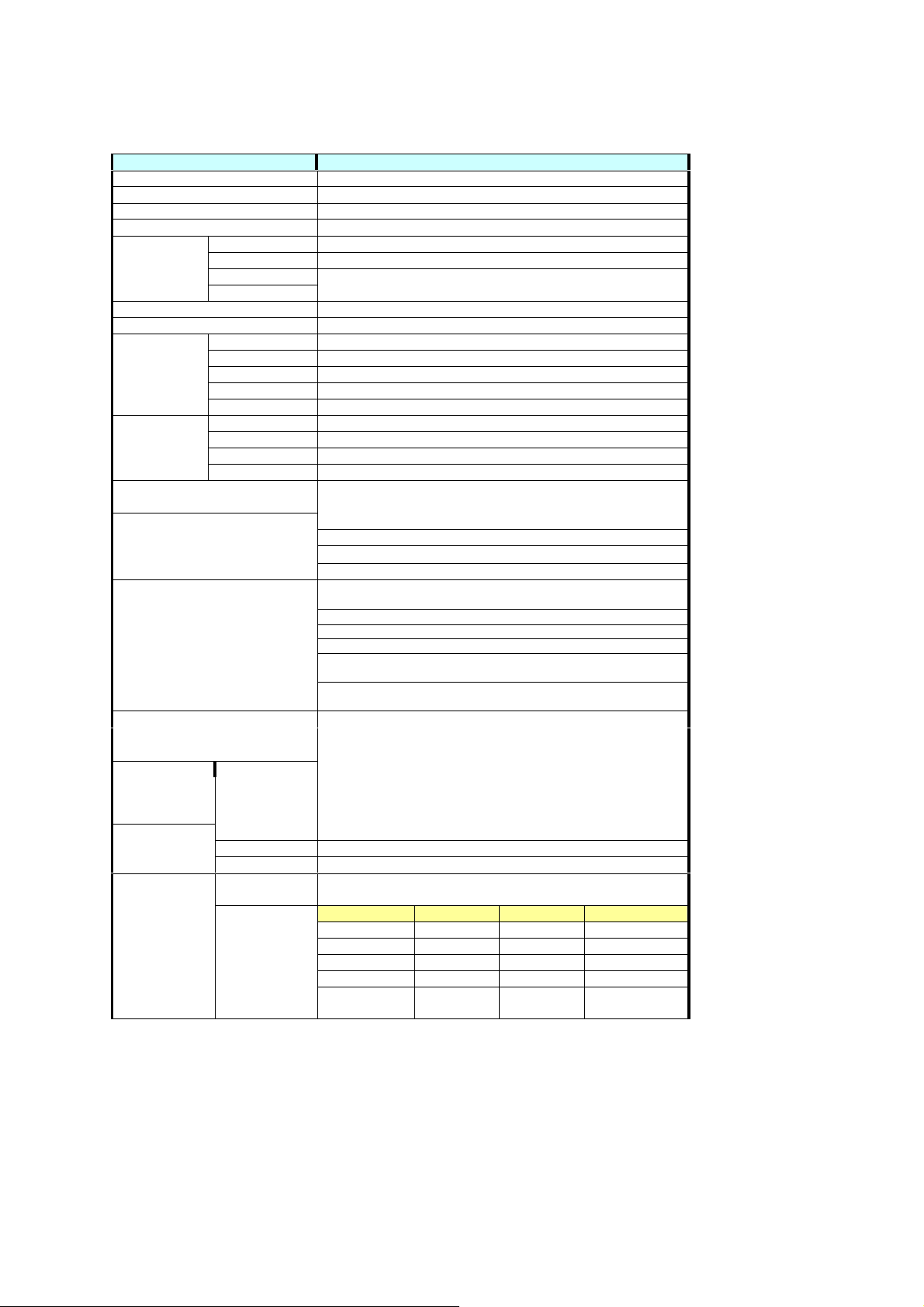
1.3 Specifications: RS12-38800 (19
Platform + EM
Platform + EM----8675B)
Platform + EMPlatform + EM
Form Factor 3U 19” Rack mount
Color Black U
Temperature 0 – 40 Degree Celsius
Humidity 5% -95%RH, Non-Condensing
Dimensions
Material SGCC
Compartment Orientation NIC module on bottom of HDD bay
HDD Bay
System Fan
Cooling
Exposure I/O
Expansion Slot 1 x PCI-E Slot or 2 x PCI-X Slot
Network Interface
Temperature
Humidity 5 ~ 95%, non condensing
Miscellaneous
Certification
Power supply
8675B)
8675B)8675B)
Height 130mm, 5.12 in
Width 442mm, 17.4 in
Depth 610mm, 24 in
Weight 30kg
Number 12
HDD Form-factor 3.5”
HDD Orientation Based on Lanner standard design
LED Indicators 2 x LED per Tray, Reference: NSB-38800 “Disk LED Activity”
Dimensions 198.2mm x 107.2 mm x27mm
Number
Fan Speed Sensing
Fan Speed Control
Others Easy to replace
LCD Module
Watchdog
Internal RTC
with Li Battery
Safety CE, FCC Class A,
EMC FCC Part 15 Class A,
ROHS EU, China
Model 1 x Zippy M3W-6950P 950W N+1 Redundant Switch Power Supply
Output
Characteristics
3 x 4700rpm (80x80x25mm)
Yes
Yes
2U CPU active heat-sink
Smart Fan x 2(Swappable)
1 x RJ45 Console Port (Front)
2 x USB Port (Front)
1 x RJ-45 for IPMI Netwrok Control(Front)
NCM-IG407A:4 Port sRJ-45 Gbe
(2 Pair By-Pass supported)
NCM-IG407B:4 Ports RJ-45 Gbe
NCM-IG411A:4 Ports SFP Gbe
NCM-IG411B : 2 Ports SFP Gbe
NCM-IG208A : 2 Ports SFP
1000Base-SX
NCM-IG208B : 2 Ports SFP
1000Base-LX (with By-Pass supported)
Operating 0℃ ~ 40℃
Ambient Storage 0℃ ~ 70℃
2 x 20 Character
Yes
Yes
Detail spec. see M3W-6950P.pdf
Connector Length Unit Mapping
24 Pin 150mm 1 MB
8 Pin 250mm 1 MB
20 Pin 150mm 1 BP
4 Pin 150mm 1 BP
2 Pin (TTL
Signal)
(with By-Pass supported)
19”””” 3U Rack
1919
150mm 1 MB
3U Rack----Mount Network Storage
3U Rack 3U Rack
Mount Network Storage
Mount Network Storage Mount Network Storage
7
Page 8

Features
Description
1.4 Specifications: EM-8675B (LGA 771 for Intel Dual
and Quad
and Quad----Core
and Quadand Quad
Processor
(2 x LGA771)
BIOS
Chipset
Memory
VGA
SSD
Security processor
On Board I/O Connector
Expansion Slot
IPMI 1 x OPMA Connector
Network interface Depends on LAN Modules
Manageability
System fan
Watch Dog Timer Super IO, 1~255
RTC Internal RTC w/ Li Battery
Temperature
Humidity
Certification
Dimension
Core (
(Clovertown
Clovertown)
CoreCore
( (
ClovertownClovertown
) XEON)
XEON)
) )
XEON)XEON)
Northbridge
Southbridge
I/O Controller
Safety
EMC
ROHS
Dual Intel LGA 771 for Dual-Core a nd Quad-Core XEON,Up to 3.0G
8M EEPROM,AMI Plug & Play BIOS (with Console Re-Direction)
Intel Blackford 5000P
Intel ESB2 (6321)
ITE8712F-S/KX-L
8 x Fully Buffer DIMM , up to 32GB
ATI ES1000
1 x Compact Flash Type II (DMA support)
Cavium CN1010 (Optional)
2 x USB Port(Front)
1 x RJ-45 Console Port(Front)
1 x RJ-45 for IPMI Netwrok Control(Front;Optional)
1 x Serial Console Port Pin Header on Board
1 x KeyBoard/Mouse Pin Header(2x4 Pin)
1 x LCM & KeyPad Pin Header(2x7 Pin)
1 x Reset Button Pin Header(2 Pin)
PCI-E Slot(Rear)
PCI-X Slot(Rear)
Temperature and Fan Speed Sensing
3 x Fan connector by IAC-FAN02A
Operating 0℃ ~ 40℃
Ambient Storage 0℃ ~ 70℃
5 ~ 95%, non condensing
CE, FCC Class A
FCC Part 15 Class A
EU, China
12” x 14”(304.8mm x 355.6mm)
LGA 771 for Intel Dual----Core
LGA 771 for Intel DualLGA 771 for Intel Dual
Core((((Woodcrest
Woodcrest))))
CoreCore
WoodcrestWoodcrest
8
Page 9

1.5 Package Contents
Carefully unpack your package and make sure that you have the following
items.
RS12-38800 Network Storage Platform x 1
Console cable (RJ-45) x 1
1.8 meters cross-over Ethernet cable x 1
1.8 meters straight-through Ethernet cable x 2
Power cable x 3
Screw Set
Slide & Bracket Set
Note: If you should find any components missing or damaged, please contact your dealer immediately
for assistance.
格格格格式化
式化:::: 項目符號及編號
式化式化
1.6 Technical Assistance
Should you have any questions or problems with your product, please
contact the Lanner sales team.
Phone: 886-2-8692-6060
Fax: 886-2-8692-6101
E-mail: sales@lannerinc.com
Prior to contacting us, we ask that you first check the electronic product
documentation for assistance. Should you still have questions, we
recommend you have the following information on hand in order to expedite
the process:
1. RS12-38800 model name
2. Part number
3. Abnormal behavior and/or error messages reported by your network
storage system
4. Your questions or a description of the problem you are experiencing
格格格格式化
式化:::: 項目符號及編號
式化式化
9
Page 10
2. System Components
2.1
EM-8675 system Board
EM-8675 is the system board bundled with the RS12-38800 Network security
platform. The succeeding sections list all EM-8572 related jumper settings
and connector pin assignments.
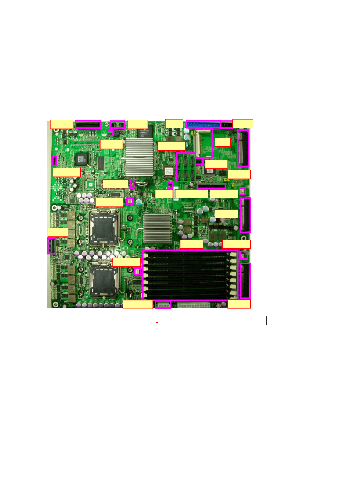
2.1.1
Board
PCIE6
VGACON1
Layo
CPUFAN1
ut
IPMI1
CCMOS2
CON3
IDE1
SATA1~6
WP1 LUSBCOM1 AUXFAN3
CN1
PKMB1
CON1
J1~J8
AUXFAN1
ATXPWR1
Figure 2 – EM-8675 Key Features
PCIE4
FPIO1
PCIE5
AUXFAN2
PCIE3
10
Page 11
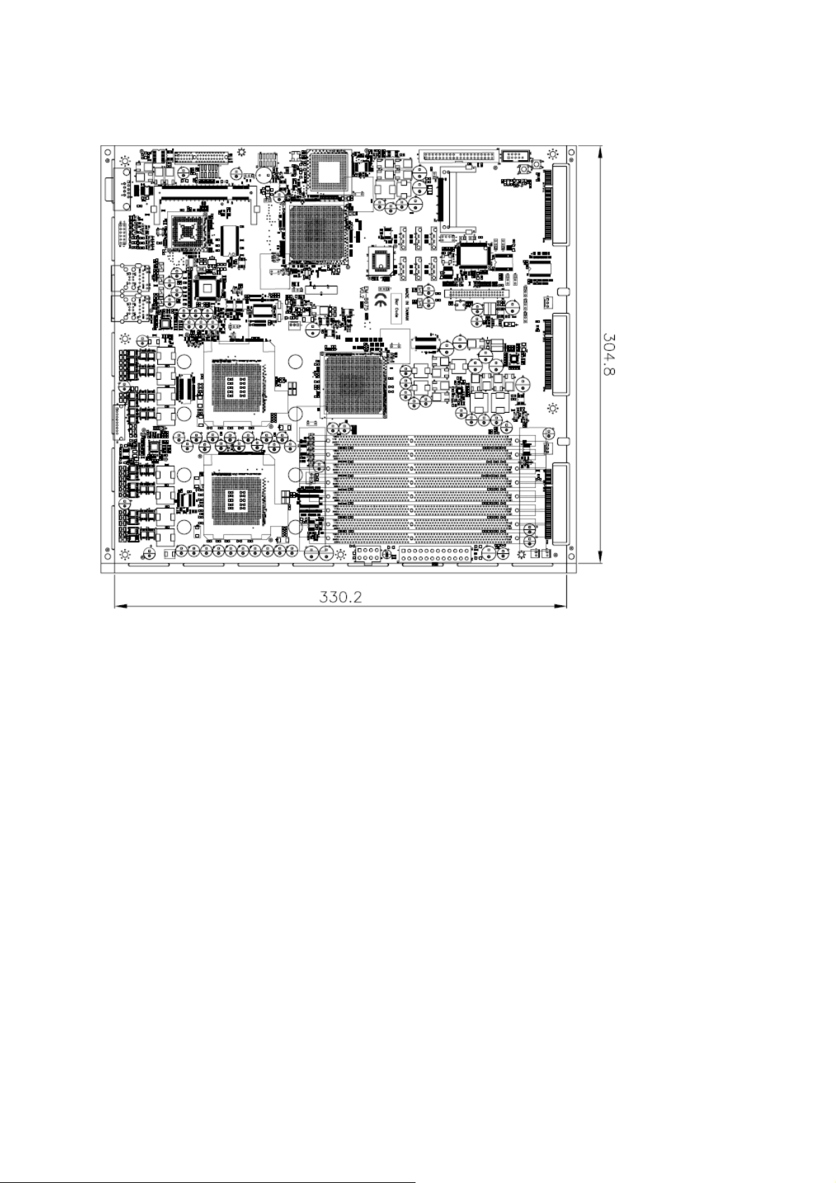
2.1.2
Dimensions (mm)
11
Figure 3 – Dimensions
Page 12

2.1.3
Jumper Settings and I/O Conne
ctors
The jumper settings and I/O connectors of the EM-8675 board
to the FW-8890. Changing these setting
damage to yo
ur
system
.
s
may
re
sult in malfunction
Jumper Settings and I/O Connector Summary for EM-8675
JUMPER
PKMB1 2x4 Header PS/2 Keyboard & Mouse Connector (2.54mm)
CCMOS2 Clear CMOS Data
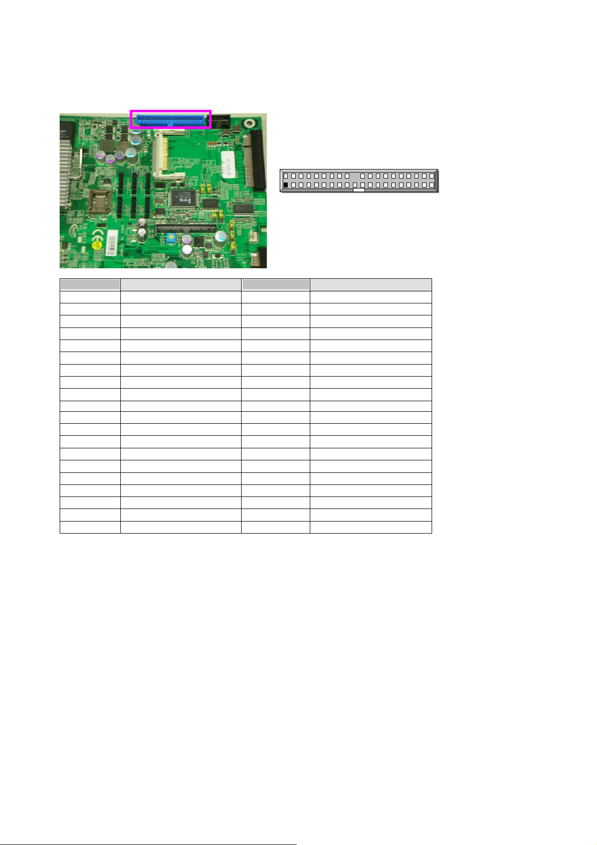
IDE1 40 Pin IDE Interface Connector (2.54mm)
CN1 Compact Flash Connector
FPIO1 9 Pin Front Panel Connector (2.54mm)
CPUFAN1/AUXFAN1
AUXFAN2 ~ AUXFAN3 3 Pin FAN Header
3 Pin Smart FAN Header
FUNCTION
are
specifi
s or
:
c
ATXPWR1 8 Pin Power Connector
LUSBCOM1 2X20 Pin BOX Connector (2.00mm)
VGACON1 12 Pin External VGA Header (2.54mm)
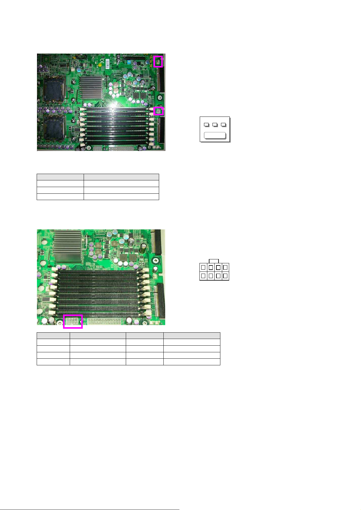
JP1 1x2 Pin Compact Flash Mode (2.54mm)
JP2 4 Pin TACT Power Button
JP3 4 Pin TACT Reset Button
JP8 ~ JP11 1x3 Pin Select KEYPAD or USB_RJ1 Lan LED (2.54mm)
JP12 2 Pin For TTL1 detect
JP13 2 Pin For TTL2 detect
JP14 1x2 Pin For SIO GPIO Pin (2.54mm)
JP15 1x2 Pin For SIO GPIO Pin (2.54mm)
JP16~JP18 1x3 Pin Select Bypass Function (2.54mm)
JP19 1x2 Pin For I2C BUS Pin (2.54mm)
CON1 10 Pin Smart FAN Connector
CON3 10 Pin SMD OPMA_LAN Connector (2.54mm)
WP1 1x3 Pin U41 Flash Rom Write Protect (2.54mm)
IPMI1 1x3 Pin Header (2.54mm)
SATA1~SATA6 180º SATA Connector
PCIEC6 PCI Express x4 Standard Connector
PCIEC3 ~ PCIEC5 Splint PCI Express x8 Standard Connector
12
Page 13

J1~J8 240Pin FB-DIMM Connector
13
Page 14
2.1.4
PKMB1:2x4
PIN NO. DESCRIPTION PIN NO. DESCRIPTION
1
3
5
7
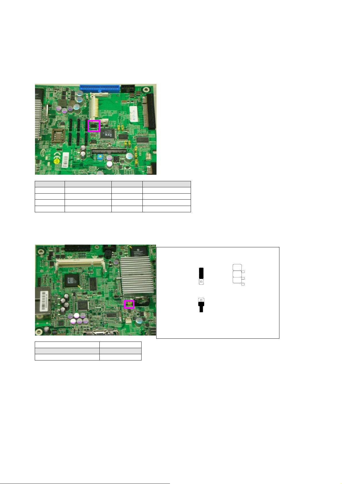
CCMOS2: Clear CMOS Data
DESCRIPTION CMOS
Normal (Default)
Clear CMOS
Conne
Header PS/2
VCC
MSDATA
KBDATA
GND
ctors Pin
2
4
6
8
1-2
2-3
Assignment
Keyboard & Mouse Connector
MSCLK
KEY
KEY
KBCLK
Clear CMOS1
CCMOS2
1
2
3
1
2
3
CCMOS2
1
2
3
14
Page 15
15
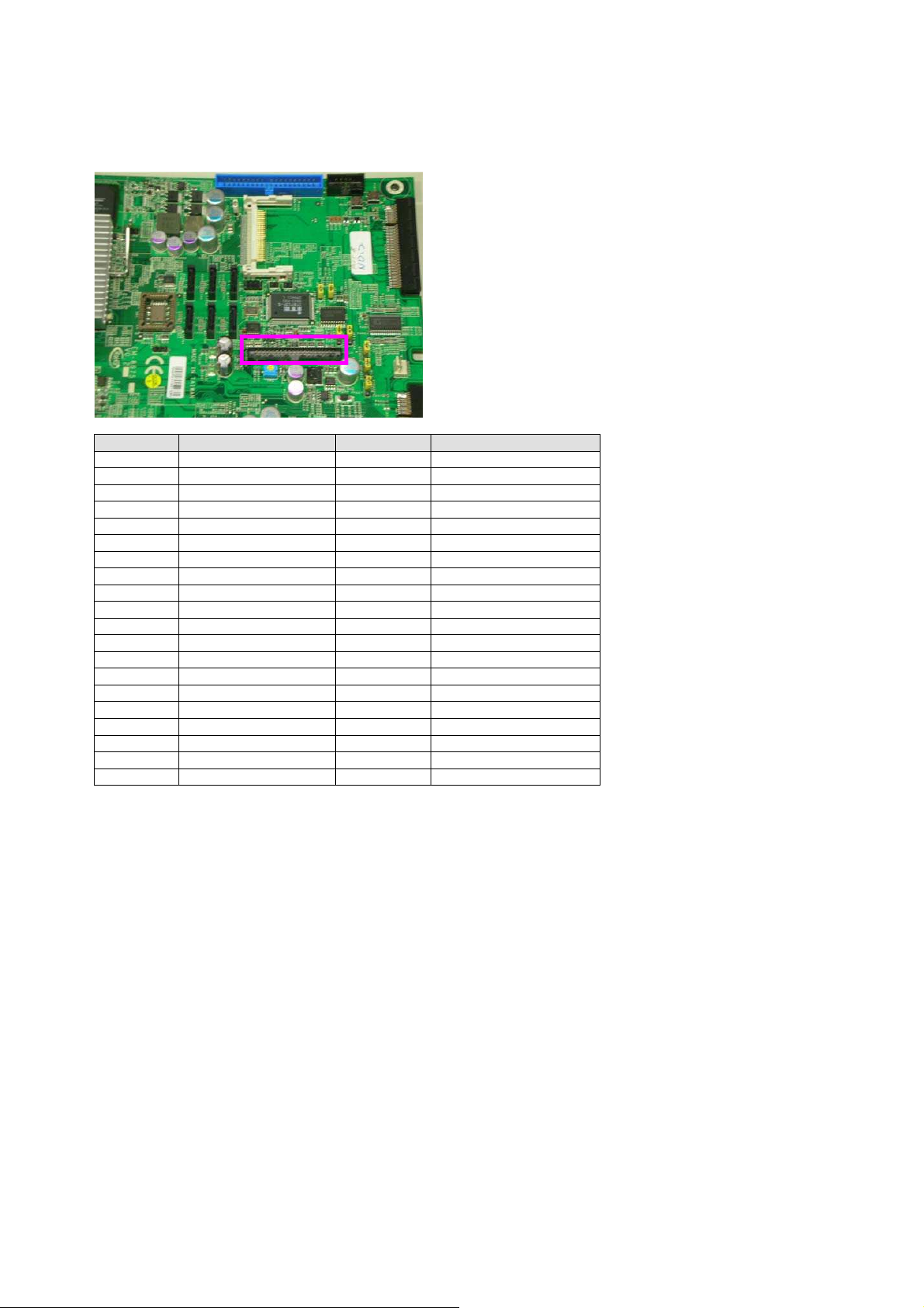
IDE1:40Pin
PIN NO. DESCRIPTION PIN NO.
1
3
5
7
9
11
13
15
17
19
21
23
25
27
29
31
33
35
37
39
IDE Interface
Reset #
Data 7
Data 6
Data 5
Data 4
Data 3
Data 2
Data 1
Data 0
Ground
DMA REQ#
IOW #
IOR #
IOCHRDY
DMA ACK #
Interrupt
SA1
SA0
HDC CS0 #
HDD Active LED #
Connect
2
4
6
8
10
12
14
16
18
20
22
24
26
28
30
32
34
36
38
40
or (2
2
1
.54mm)
IDE1
DESCRIPTION
Ground
Data 8
Data 9
Data 10
Data 11
Data 12
Data 13
Data 14
Data 15
KEY
Ground
Ground
Ground
Ground
Ground
NC
PD80P / SD80P
SA2
HDC CS1 #
Ground
40
Page 16
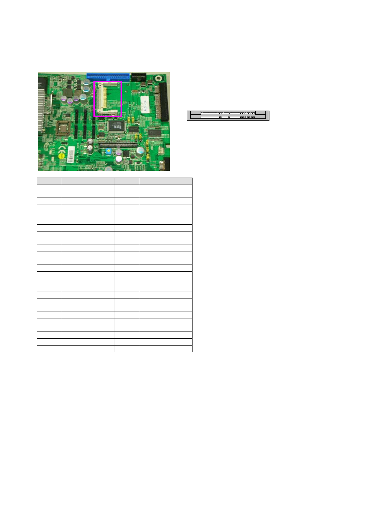
CN1:Compact
Flash Connector
PIN NO DESCRIPTION PIN NO DESCRIPTION
1
2
3
4
5
6
7
8
9
10
11
12
13
14
15
16
17
18
19
20
21
22
23
24
25
GND
DATA3
DATA4
DATA5
DATA6
DATA7
CE1#
NC
GND
NC
NC
NC
CFVCC3
NC
NC
NC
NC
A2
A1
A0
DATA0
DATA1
DATA2
WP
CD2-
26
27
28
29
30
31
32
33
34
35
36
37
38
39
40
41
42
43
44
45
46
47
48
49
50
CD1-
DATA11
DATA12
DATA13
DATA14
DATA15
CE2#
NC
IOR#
IOW#
WE#
READY#
CFVCC3
CSEL
NC
RESET
WAIT#
INPACK#
REG#
DASP#
DIAG#
DATA8
DATA9
DATA10
GND
CN1
16
Page 17
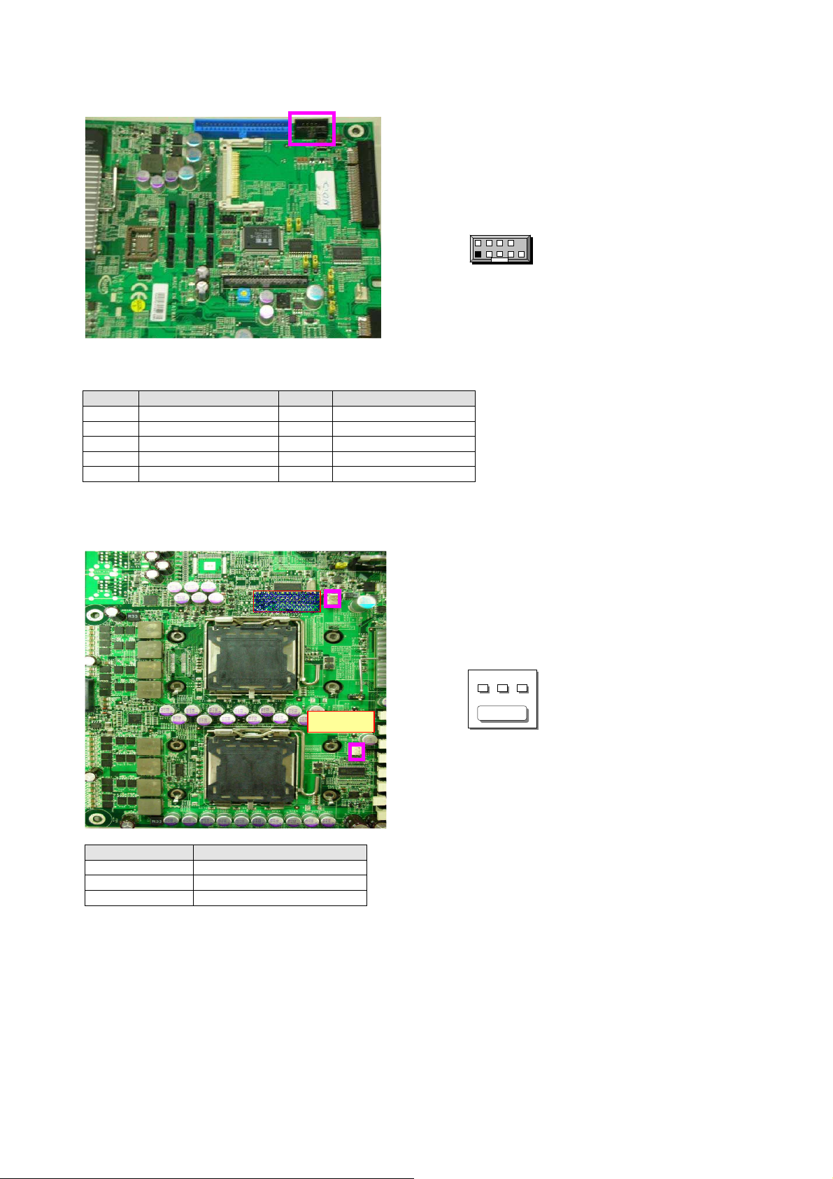
FPIO1:9Pin
PIN NO DESCRIPTION PIN NO DESCRIPTION
1
3
5
7
9
HDD_LEDH
HDD_LEDL
Ground
FP_RST#_N
NMI_N
CPUFAN1/AUXFAN1:3Pin Smart
PIN NO DESCRIPTION
1
2
3
Front Pa
Ground
VFAN1~2
FAN Speed
nel Connector (2.54mm)
2
4
6
8
10
SP_LEDH
SP_LEDL
Ground
PS_ON#
KEY
FAN
CPUFAN1
AUXFAN1
Header
2 10
1 9
FPIO1
1 2 3
17
Page 18
AUXFAN2 ~ AUXFAN3:3
PIN NO DESCRIPTION
1
2
3
ATXPWR1:
PIN NO. DESCRIPTION PIN NO. DESCRIPTION
1
2
3
4
Ground
VFAN1~2
FAN Speed
8Pin Power C
Ground
Ground
Ground
Ground
Pin
FAN
AUXFAN3
AUXFAN2
onnector
5
6
7
8
Header
P12V_A
P12V_A
P12V_B
P12V_B
8 5
4 1
1 2 3
18
Page 19
LUSBCOM1:2 x 20
PIN NO. DESCRIPTION PIN NO. DESCRIPTION
1
3
5
7
9
11
13
15
17
19
21
23
25
27
29
31
33
35
37
39
NDCDB#
NSINB
NSOUTB
NDTRB#
Ground
+5V
CTR_GRN
P5V_USB4
USB_4N_C
USB_4P_C
LPT17
LPT14
LPT3
LPT5
LPT7
LPT9
LCD-
KPA1_JP
KPA3_JP
FP_RST#_N
Pin BOX Conne
2
4
6
8
10
12
14
16
18
20
22
24
26
28
30
32
34
36
38
40
ctor
(2.00mm)
NDSRB#
NRTSB#
NCTSB#
NRIB#
Ground
+5V
HDD_LED#
CTR_RED
P5V_USB5
USB_5P_C
USB_5N_C
Ground
VEE(LCD)
LPT16
LPT2
LPT4
LPT6
LPT8
KPA2_JP
KPA4_JP
19
Page 20
VGA1: External VGA Conne
ctor
(12 Pin Header)
2 12
PIN NO. DESCRIPTION PIN NO. DESCRIPTION
1
3
5
7
9
11
R
G
B
H-SYNC
V-SYNC
Detect-display Data
2
4
6
8
10
12
Ground
Ground
Ground
Ground
Ground
Deteck-display CLOCK
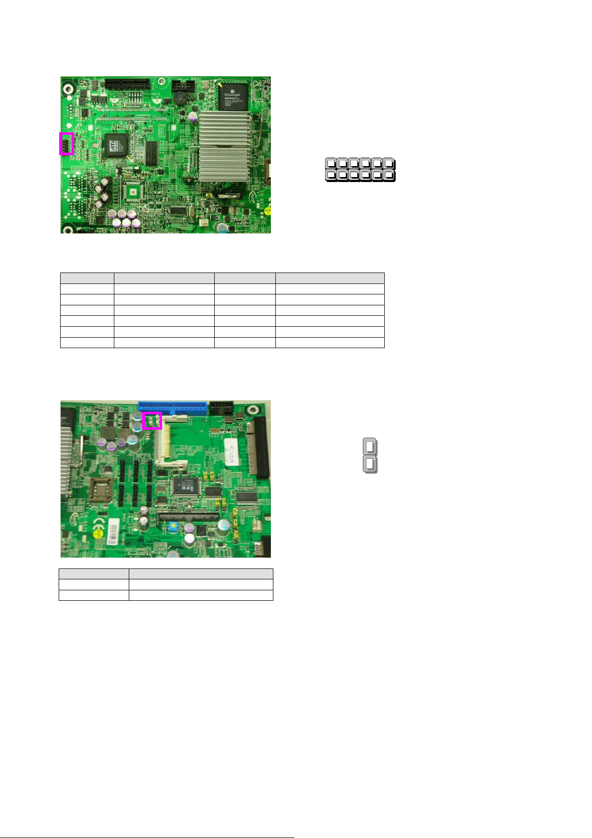
JP1:1x2
Pin Compact
Flash
Mode (2.54mm)
PIN NO. DESCRIPTION
OPEN
SHORT
Slave
Master
Default JP1 (1-2)
1 11
1
JP1
2
20
Page 21

JP2:4
Pin TACT Power
PIN NO. DESCRIPTION
1
2
3
4
Ground
Ground
PS_ON#
PS_ON#
JP3:4
Pin TACT Reset Button
PIN NO. DESCRIPTION
1
2
3
4
Ground
Ground
PS_ON#
PS_ON#
Bu
tton
2 1
○
_○ ○
4 3
2 1
○
_○ ○
4 3
21
Page 22

JP8~JP11:1x3
Pin Select KEYPAD
PIN NO. DESCRIPTION
1
2
3
Default (1-2),(2-3) for ODM
JP12:2Pin
PIN NO. DESCRIPTION
1
2
KPAx
KPAx_JP
Lan_LEDx
For TTL1
Ground
TTL1(IT8712F GP30)
detect
or
USB_RJ1
JP8/JP10
JP9/JP11
Lan
LED
3
1
JP12
1
2
22
Page 23

JP13:2Pin
For TTL2
PIN NO. DESCRIPTION
1
2
JP14:1x2
PIN NO. DESCRIPTION
1
2
Ground
TTL1(IT8712F GP31)
Pin
For SIO
Ground
IT8712F GP16
detect
GPIO Pin
1
2
1
2
(2.54
mm)
JP13
23
Page 24

JP15:1x2
Pin
For SIO
PIN NO. DESCRIPTION
1
2
JP16~JP18:1x3
Ground
IT8712F GP17
Pin Select Bypass Function (2.54mm)
PIN NO. DESCRIPTION
1
2
3
IT8712F(GP32~34)
PCIEC3~5 Pin B12
Ground
Default (1-2,Bypa
ss
Enable)
GPIO Pin
(2.54
JP16
JP17
JP18
mm)
1
2
3
1
24
Page 25

JP19:1x2
Pin
For I2C BUS
PIN NO. DESCRIPTION
1
2
CON1:
PIN NO. DESCRIPTION
1
2
3
4
5
6
7
8
9
25
I2C_CHIPSET_SCL
I2C_CHIPSET_SCA
10
Pin Smart
Ground
FAN3 speed
VFAN3
Ground
FAN4 speed
VFAN4
Ground
FAN5 speed
VFAN5
FAN
Pin (2.54mm)
Conne
ctor
1
2
Page 26

10
Ground
26
Page 27

CON3:
PIN NO. DESCRIPTION PIN NO. DESCRIPTION
1
3
5
7
9
WP1:1x3
PIN NO. DESCRIPTION
1
2
3
10
Pin SMD OPMA_LAN C
MCARD_TX_H
MCARD_TX_L
POE_GND
POE_PWR
LAN_BUSY_LED_L
Pin U
FWP#
Ground
NC
41
Fla
sh Rom Wr
2
4
6
8
10
onnector
MCARD_RX_H
MCARD_RX_L
POE_GND
POE_PWR
LAN_LINK_LED_L
(2.54mm)
ite Protect (2.54mm)
3
1
27
Page 28

IPMI1:1x3
Pin Header (2.54mm)
PIN NO. DESCRIPTION
1
2
3
IPMB_SDA
GND
IPMB_SCL
SATA1~SATA6:180º
SATA
CONNECTOR
SATA1/SATA2/SATA3
SATA4/SATA5/SATA6
PIN NO. DESCRIPTION PIN NO. DESCRIPTION
1
3
5
7
9
GND
SATA_TXN
SATA_RXN
GND
GND
2
4
6
8
SATA_TXP
GND
SATA_RXP
GND
3
1
28
Page 29

PCIEC6:PCI Ex
press x4
Standard Conne
PCIEC3~PCIEC5:Splint PCI Express
ctor
x8
Standard Connector
PCIE 5
PCIE 4
PCIE 3
29
Page 30

PIN NO. DESCRIPTION PIN NO. DESCRIPTION
B1
B2
B3
B4
B5
B6
B7
B8
B9
B10
B11
B12
B13
B14
B15
B16
B17
B18
B19
B20
B21
B22
B23
B24
B25
B26
B27
B28
B29
B30
B31
B32
B33
B34
B35
B36
B37
B38
B39
+12V
+12V
+12V
GND
SMCLK
SMDAT
GND
+3.3V
JTAG1
3.3VAUX
WAKE#
BYPASS Mode
GND
PETP0
PETN0
GND
PRSNT#2
GND
PETP1
PETN1
GND
GND
PETP2
PETN2
GND
GND
PETP3
PETN3
GND
REFCLKB+
REFCLKB-
GND
PETP4
PETH4
GND
GND
PETP5
PETN5
GND
B1
B2
B3
B4
B5
B6
B7
B8
B9
B10
B11
B12
B13
B14
B15
B16
B17
B18
B19
B20
B21
B22
B23
B24
B25
B26
B27
B28
B29
B30
B31
B32
B33
B34
B35
B36
B37
B38
B39
PRSNT1#
+12V
+12V
GND
JTAG2
JTAG3
JTAG4
JTAG5
+3.3V
+3.3V
PERST#
GND
REFCLKA+
REFCLKA-
GND
PERP0
PERN0
GND
RSVD
GND
PERP1
PERN1
GND
GND
PERP2
PERN2
GND
GND
PERP3
PERN3
GND
RSVD
RSVD
GND
PERP4
PERN4
GND
GND
PERP5
30
Page 31

B40
B41
GND
PETP6
B40
B41
PERN5
GND
31
Page 32

B42
B43
B44
B45
B46
B47
B48
B49
PETN6
GND
GND
PETP7
PETN7
GND
PRSNT2#
GND
J1~J8:240Pin
or
GND
PERP6
PERN6
GND
GND
PERP7
PERN7
GND
J1
J2
J3
J4
J5
J6
J7
J8
B42
B43
B44
B45
B46
B47
B48
B49
FB
-DIMM Connect
32
Page 33

RS12-38800
33
Ethernet Ports
2.2 Mechanical Overview
This section of the manual describes the mechanical and device
nomenclature of the RS12-38800.
2.2.1 Face Panel LED Status and Behavior
Figure 5 – RS12-38800 Front Panel
The following table provides a description of each LED on the RS12-38800
front panel:
Console Port: The console port cable connects RS12-38800 to
the host PC via. The Default baud rate is 115200
• LAN Connector: Require an Ethernet RJ-45 cable
• LCM & Keypad: Please reference the Appendix B
LED Color Status
PWR
HDD
Link/ACT
Status Lanner Provide the Sample Codes(Please
Green
N/A Off No power connected
Yellow
N/A Off No Data is being accessed
Green On LAN is connected
Orange Flash Data is being accessed
On Indicates when RS12-38800 power is
switched ON
On Hard disk is being accessed
reference the Driver/ Manual CD, under
“LED Status” for more information)
Description
Page 34

34
2.2.2 Rear View
:
<sp>
RS12-38800
Figure 6 – RS12-38800 Rear View
Warning: Faulty or improper use of the power adaptor may cause permanent damage to
the power supply and the RS12-38800. Plug the adaptor to an electrical wall outlet that
matches its specifications.
刪除
刪除
刪除刪除
Page 35

RS12-38800
35
Step1
Step2
Step3
Step4
3. Hardware Installation Guide
3.1 CPU Installation
Step 1: Open Socket by pushing lever down and away from socket.
Step 2: Open load plate.(Don’t Touch Socket Contacts)
Step 3: Align notches with socket
Step 4: Close load plate.
刪除
刪除: Removing the Top
刪除刪除
Cover
Step 1 : Unscrew
screws from the system.
Step 2 : Pull up the top
cover
<sp><sp>
3.2 System Memory
Position the Fully Buffer DIMM memory module to the DIMM socket properly,
so the notch on the memory module fits the socket. Push the memory card
into the socket.
Note: The Fully Buffer DIMM memory module requires the proper orientation in order to fit
into the socket properly.
Warning: Please note that the DIMM socket must be used in sequence.
格格格格式化
式化:::: 項目符號及編號
式化式化
Page 36

RS12-38800
36
Installing Hard Disk
3.3 Installing Compact Flash Card
刪除
刪除:
刪除刪除
Drive
Step 1: screws the bracket.
Step 2: Moving the hard
disk bracket.
Step 3:
Step 4:
<sp><sp><sp><sp>
<sp>
Carefully insert the Compact Flash card into the slot as shown in the
illustration above.
3.4 Install the Rail slider
Page 37

RS12-38800
37
Page 38

RS12-38800
38
Page 39

RS12-38800
39
Page 40

RS12-38800
40
"Rack Mount Instructions - The following or similar rack-mount instructions are
included with the installation instructions:
i.
rack assembly, the operating ambient temperature of the rack environment may be
greater than room ambient. Therefore, consideration should be given to installing
the
equipment in an environment compatible with the maximum ambient temperature
(Tma) specified by the manufacturer.
ii.
should be such that the amount of air flow required for safe operation of the
equipment is not compromised.
iii.
be such that a hazardous condition is not achieved due to uneven mechanical
loading.
iv.
of the equipment to the supply circuit and the effect that overloading of the circuits
might have on overcurrent protection and supply wiring. Appropriate consideration
of equipment nameplate ratings should be used when addressing this concern.
Elevated Operating Ambient - If installed in a closed or multi-unit
Reduced Air Flow - Installation of the equipment in a rack
Mechanical Loading - Mounting of the equipment in the rack should
Circuit Overloading - Consideration should be given to the connection
v. Reliable Earthing - Reliable earthing of rack-mounted
equipment should be maintained. Particular attention should be given to
supply connections other than direct connections to the branch circuit (e.g. use
of power strips)."
CAUTION :
Slide/rail mounted equipment is not to be used as a shelf or a work space.
Page 41

RS12-38800
41
4. BIOS Setup
BIOS Setup
AMI’s ROM BIOS provides a built-in Setup program that allows users to modify the
basic system configuration and settings. The modified data will be stored in a
battery-backed CMOS RAM so that this data will be retained even when the power
is turned off. In general, the information saved in the CMOS RAM remains
unchanged unless there is a configuration change in the system, such as hard drive
replacement or new equipment installment.
Running AMI BIOS
The Setup Utility is stored in the BIOS ROM. When the power of the computer
system is turned on, a screen message will appear to give you an opportunity to call
up the Setup Utility while the BIOS will enter the Power On Self Test (POST)
routines. The POST routines perform various diagnostic checks while initializing the
board hardware. If the routines encounter an error during the tests, the error will
be reported in one of two ways, a series of short beeps or an error message on the
screen. There are two kinds of errors, fatal and non-fatal. The system can usually
continue the boot up sequence with non-fatal errors. Non-fatal error messages
usually appear on the screen along with the following
Instructions:
“ Press <F1> to RESUME ”
Write down the message and press the F1 key to continue the boot up sequence.
After the POST routines are completed, the following message appears:
“ Press DEL to enter SETUP ”
Entering Setup
Turn on the power of the computer system and press <Del> immediately. If you
don’t have the chance to respond, reset the system by simultaneously pressing the
<Ctrl>, <Alt> and <Delete> keys, or by pushing the ‘ Reset ’ button on the system
cabinet. You can also restart by turning the system OFF then ON.
CMOS Setup Utility
To access the AMI BIOS SETUP program, press the <DEL> key. The screen display
will appear as shown below:
Page 42

RS12-38800
42
4.1 Main Program Screen
This screen provides access to the utility‘s various functions.
Listed below is explanation of the keys displayed at the bottom of the screen:
<ESC>: Exit the utility.
<↑↓→ ←>: Use arrow keys↑↓→ ← to move cursor to your desired selection.
<F1>: General Help
<F10>: Saves all changes made to Setup and exits program.
Main
For changing the basic system configuration
Advanced
Boot
Security For changing the Security setting
Exit
For selecting the exit options and loading default
For changing the advanced system settings
For changing the system boot configuration
Settings
Page 43

RS12-38800
43
4.2 Main CMOS Setup
When you select the “Main CMOS SETUP” on the main program, the screen display
will appears as:
The Main CMOS Setup utility is used to configure the following components such as
date, time, display and memory.
Processor
Displays the auto-detected CPU specification
System Memory
System Time [xx:xx: xxxx]
System Date [Day xx/xx/xxxx]
Displays the auto-detected system memory
Allows
you to set the system time.
Allows you to set the system date.
Page 44

RS12-38800
44
4.3 Advanced Menu
When you select the “Advanced Menu” on the main program, the screen display will
appear as:
The following explains the options for each of the features as listed in the above
menu:
IDE Configuration:
The items in this menu allow you to set or change the
configurations. Four IDE devices were installed in the system. Select an
item then press <Enter>if you wish to configure the item.
ATA/IDE Configuration: These 2 items allow you to select the ATA/IDE and SATA
Page 45

RS12-38800
45
configuration. Select [Disabled] in ATA/IDE Configuration if you want to disable
both ATA/IDE configuration. Select [Compatible] or [Enhanced] to use the IDE,
S-ATA and PATA devices. Refer to the following tables for details.
Primary, Third and Fourth IDE Master/Slave
While entering Setup, the BIOS automatically detects the presence of IDE devices.
There is a separate sub-menu for each IDE device. Select a device item then press
<Enter> to display the IDE device information.
The BIOS automatically detects the values opposite the dimmed items
(Device, Vendor, Size, LBA Mode, Block Mode, PIO Mode, Async DMA, Ultra
DMA, and SMART monitoring). These values are not user-configurable.
These items show N/A if no IDE device is installed in the system.
Hard disk boot priority: Select boot sequence for onboard (or add-on cards) SCSI,
RAID, etc.
Type: Selects the type of IDE drive. Setting to Auto allows automatic selection of
the appropriate IDE device type. Select CDROM if you are specifically configuring a
CD-ROM drive. Select ARMD (ATAPI Removable Media Device)
If your device is either a ZIP, LS-120, or MO drives.
Configuration options: [Not Installed] [Auto] [CDROM] [ARMD]
LBA/Large Mode: Enables or disables the LBA mode. Setting to Auto enables the
LBA mode if the device supports this mode, and if the device was not previously
formatted with LBA mode disabled.
Page 46

RS12-38800
46
Configuration options: [Disabled] [Auto].
Block (Multi-sector Transfer): Enables or disables data multi-sector transfers.
When set to Auto, the data transfer from and to the device occurs multiple sectors
at a time if the device supports multi-sector transfer. When set to [Disabled], the
data transfer from and to the device occurs one sector at a time.
Configuration options: [Disabled] [Auto].
PIO Mode: Selects the PIO mode,
Configuration options: [Auto] [0] [1] [2] [3] [4].
DMA Mode: Selects the DMA mode.
Configuration options: [Auto] [DMA0][SWDMA1] [SWDMA2] [MWDMA0]
[MWDMA1] [MWDMA2] [UDMA0] [UDMA1] [UDMA2] [UDMA3] [UDMA4] [UDMA5].
SMART Monitoring: Sets the Smart Monitoring, Analysis, and Reporting
Technology. Configuration options: [Auto] [Disabled] [Enabled].
32Bit Data Transfer: Enables or disables 32-bit data transfer.
Configuration options: [Disabled] [Enabled].
Hard Disk Write Protect: Write protection effective only if device is accessed
through BIOS.
Configuration options: [Disabled] [Enabled].
IDE Detect Time Out (Sec): Select the time out value for detecting ATA/ATAPI
device(s).
Configuration options: [0] [5] [10] [15] [20] [25] [30] [35]
ATA (PI) 80Pin Cable Detection: Select the mechanism for detecting 80Pin ATA
(PI) cable.
Configuration options: [Host & Device] [Host] [Device]
Super IO Configuration: Press <Enter> to enter the sub-menu and the following
screen appears:
Serial Port1/2 Address:
These items specify the base I/O port addresses of the onboard Serial Port 1
Page 47

RS12-38800
47
Selecting [Auto] allows BIOS to automatically determine the correct base I/O
port address. Settings: [3F8/IRQ4], [2F8/IRQ3], [3E8/IRQ4], [2E8/IRQ3] and
[Disabled].
Serial Port2 Mode:
This item allows you to select mode for Serial Port2. Setting options: [Normal],
[IrDA], [ASK IR].
Parallel Port Address: Allows you to select the Parallel Port base addresses.
Configuration options: [Disabled] [378] [278] [3BC].
Parallel Port Mode: Allows you to select the Parallel Port mode.
Configuration options: [Normal] [Bi-directional] [EPP] [ECP].
Parallel Port IRQ:
Configuration options: [IRQ5] [IRQ7].
Restore on AC Power Loss by IO
This setting specifies whether your system will reboot after a power failure or
interrupt occurs. Available settings are:
[Power Off] Leaves the computer in the power off state.
[Power On] Leaves the computer in the power on state.
[Last State] Restores the system to the previous status before power
failure or interrupt occurred.
Hardware Health Configuration: Press <Enter> to enter the sub-menu and the
following screen appears:
H/W Health Function: Enable/Disable Hardware Health Monitoring Device.
Page 48

RS12-38800
48
SYS/CPU/Power FAN Speed, CPU Vcore, FBD_VCC, +3V, +5V, +12V,
FBD_VTT, -12V, 5VSB,VBAT: These items display the current status of all of the
monitored hardware devices components such as CPU voltages, and all fans’
speeds.
USB Configuration: Press <Enter> to enter the sub-menu and the following
screen appears:
Legacy USB Support: Enables support for legacy USB. AUTO disable legacy
support if no USB devices are connected.
Configuration options: [Disable] [Enable] [Auto].
USB 2.0 Controller Mode: Configures the USB 2.0 controller in HiSpeed or
FullSpeed).
Configuration options: [FullSpeed] [HiSpeed].
BIOS EHCI Hand-Off: this is a workaround for Oses without EHCI hand-off
support. The EHCI ownership change should claim by EHCI driver.
Configuration options:[Disable] [Enable].
Hotplug USB FDD Support: A dummy FDD device is created that will be
associated with the hot plugged FDD later. AUTO creates this dummy device only if
there is no USB FDD present.
Configuration options: [Disable] [Enable] [Auto].
USB Mass Storage Device Configuration: Press <Enter> to enter the
sub-menu and the following screen appears:
Page 49

RS12-38800
49
USB MASS Storage Reset Delay: Number of seconds POST waits for the USB
mass Storage device after start unit command.
Emulation Type: If AUTO, USB devices less than 530MB will be emulated as floppy
and remaining as hard drive. Forced FDD option can be used to force a HDD
formatted drive to boot as FDD (Ex. ZIP drive).
AHCI Configuration: Press <Enter> to enter the sub-menu and the following
screen appears:
AHCI Port0/1/2/3/4/5[Not Detected]: While entering setup, BIOS auto detects the presence of
IDE devices. This displays the status of auto detection of IDE device.
Remote Access Configuration: Press <Enter> to enter the sub-menu and enable
Remote Access, the following screen appears:
Page 50

RS12-38800
50
Serial port number: Select Serial Port for console redirection.
Serial Port Mode: Select Serial Port setting.
Flow Control: Select Flow Control for console redirection.
Redirection After BIOS POST: DISABLE, Turns off the redirection after POST.
Boot Loader, Redirection is active during POST and during Boot Loader. Always,
Redirection is always active.
Terminal Type: Select the target terminal type.
VT-UTF8 Combo Key Support: Enable VT-UTF8 Combination Key Support for
ANSI/VT100 terminals.
Sredir Memory Display Delay: Gives the delay in seconds to display memory
information.
Page 51

RS12-38800
51
4.4 Boot Menu
The Boot menu items allow you to change the system boot options. Select
an item then press <Enter> to display the sub-menu.
Boot Setting Configuration: Press <Enter> to enter the sub-menu and the
following screen appears:
Quick Boot :
while booting to decrease the time needed to boot the system. When set to [Disabled], BIOS
performs all the POST items. Configuration options: [Disabled] [Enabled]
Full Screen Logo: This allows you to enable or disable the full screen logo display
feature. Configuration options: [Disabled] [Enabled]
Add On ROM Display Mode: Sets the display mode for option ROM.
Enabling this item allows the BIOS to skip some power on self tests (POST)
Page 52

RS12-38800
52
Configuration options: [Force BIOS] [Keep Current].
Bootup Num-Lock: Allows you to select the power-on state for the NumLock.
Configuration options: [Off] [On]
PS/2 Mouse Support: Allows you to enable or disable support for PS/2 mouse.
Configuration options: [Disabled] [Enabled] [Auto].
Wait for ‘F1’ If Error: When set to Enabled, the system waits for the F1 key to be
pressed when error occurs. Configuration options: [Disabled] [Enabled].
Hit ‘DEL’ Message Display: When set to Enabled, the system displays the
message. “Press DEL to run Setup” during POST. Configuration options: [Disabled]
[Enabled].
Interrupt 19 Capture: When set to [Enabled], this function allows the option
ROMs to trap Interrupt 19. Configuration options: [Disabled] [Enabled].
Boot Device Priority: Press <Enter> to enter the sub-menu and the following
screen appears:
1st ~ xxth Boot Device: These items specify the boot device priority sequence
from the available devices. The number of device items that appears on the screen
depends on the number of devices installed in the system. Configuration options:
[xxxxx Drive] [Disabled].
Page 53

RS12-38800
53
4.5 Security Menu
Press <Enter> to enter the sub-menu and the following screen appears:
Type the password, up to 6 characters in length, and press <Enter>. The typed
password now will replace any previously set password from CMOS memory. You
will be prompted to confirm the password. Retype the password and press <Enter>.
You may also press <Esc> to abort the selection and not enter a password.
To clear a set password, just press <Enter> when you are prompted to enter the
password. A message will show up confirming the password will be disabled. Once
the password is disabled, the system will boot and you can enter Setup without
entering any password.
When a password has been set, you will be prompted to enter it every time you try
to enter Setup. This prevents an unauthorized person from changing any part of
your system configuration.
Change Supervisor Password: Install or Change the password.
Change User Password: Install or Change the password.
Boot Sector Virus Protection: Enable/Disable Boot Sector Virus protecting.
Page 54

RS12-38800
54
4.6 Exit Menu
Press <Enter> to enter the sub-menu and the following screen appears:
Save Changes and Exit: Once you are finished making your selections, choose
this option from the Exit menu to ensure the values you selected are saved to the
CMOS RAM. An onboard backup battery sustains the CMOS RAM so it stays on even
when the PC is turned off. When you select this option, a confirmation window
appears. Select Yes to save changes and exit.
Discard Changes and Exit: Select this option only if you do not want to save the
changes that you made to the Setup program. If you made changes to fields other
than System Date, System Time, and Password, the BIOS asks for a confirmation
before exiting.
Discard Changes: This option allows you to discard the selections you made and
restore the previously saved values. After selecting this option, a confirmation
appears. Select Yes to discard any changes and load the previously saved values.
Load Optimal/Failsafe Defaults: This option allows you to load the default
values for each of the parameters on the Setup menus. When you select this option
or if you press <F9/F8>, a confirmation window appears. Select Yes to load default
values. Select Exit & Save Changes or make other changes before saving the values
to the non-volatile RAM.
Page 55

RS12-38800
55
A. Appendix A: Power Supply
A.1 Power Supply Specifications
AC Input Specifications: Voltage 90 ~ 264 VAC FULL RANGE
Output Specifications
Output
Voltage
+5V
-5V 0.2 1.2 ±5%/-10% ±1% 120mV
+12V 6 60.00 +6% ±1% 120mV
-12V 0.2 1.20 +5%/-10% ±1% 120mV
+3.3V 3.5
+5VSB 0.4
A.2 Features:
Output
Current
Min.
Output
Current Max.
6 56.00 ±5% ±1% 70mV
44
3.5
Output
Current Peak
Regulation
±5% ±1% 70mV
+5%/-6% ±1% 70mV
Load
Regulation
Line
Output Ripple &
Noise Max.[P-P]
Active PFC (full range), meets IEC-1000-3-2 Class D requirements
12V, Maximum Current: 60A
Temperature Range: Operating ranges from 0℃~40℃, Storage ranges
from -20℃~70℃
EMI: FCC CLASS B, CISPR 22 CLASS B
Safety: UL 1950, CSA 22.2 No./ 950, TUV IEC 950
Hot-Swappable / Hot-Pluggable Redundancy Function
Uses 48-pin industrial connectors
Cooling: 38 x 38 x 28mm DC Fans (Module)
AC Inlet in each module
Page 56

RS12-38800
56
Watch Dog Timer Control
= 01 Power LED pin is drived
= 10 Power LED pin is a 1Hz
Bit 2 : Enable the rising edge
zerovalue to Watch Dog
B. Appendix B: Watchdog Timer
B.1 Introduction
Most systems need to be self-reliant. If an error should occur it is typically
not possible to wait for the system to be rebooted manually. In some cases,
the system is simply not accessible to human operators. If such systems
should ever hang, they would be permanently disabled. In other cases, the
speed at which a human operator would reset the system would be too slow
to meet the uptime requirements of the product.
A watchdog timer is a piece of hardware that can be used to automatically
detect system anomalies and reset the processor in the case any problems
are found. Generally speaking, a watchdog timer is based on a counter that
counts down from an initial value to zero. The software selects the counter's
initial value and periodically restarts it. Should the counter reach zero
before the software restarts it, the software is presumed to be
malfunctioning, and the processor's reset signal is asserted. Thus, the
processor will be restarted as if a human operator had cycled the power.
Note: The watchdog function is the Intel 82571EB. Lanner provides sample
codes in the Manual/ Driver CD under the path:// WATCHDOG
刪除
刪除: Detail Register
刪除刪除
Descriptions
A watchdog action consists
of a series of watchdog
instructions. A watchdog
instruction is the operation
on a register region. This
section describes the detail
register in LPC
I/O(W83627HF).
Register
Watch Dog Timer is
controlled by CRF5, CRF6,
CRF7 of Logical Device.
CRF5 (PLED mode
register. Default 0x00)
Bit 7-6 : select PLED mode
= 00 Power LED pin is
tri-stated.
low.
toggle pulse with 50 duty
cycle
= 11 Power LED pin is a
1/4Hz toggle pulse with 50
duty cycle.
Bit 5-4 : Reserved
Bit 3 : select WDTO count
mode.
= 0 second
= 1 minute
of keyboard Reset(P20) to
force Time-out event.
= 0 Disable
= 1 Enable
Bit 1-0 : Reserved
CRF6 (Default 0x00)
Watch Dog Timer Time-out
value. Writing a non-zero
value to this register causes
the counter toload the value
to Watch Dog Counter and
start counting down. If the
Bit 7 and Bit 6 are set,
anyMouse Interrupt or
Keyboard Interrupt event
will also cause the reload of
previously-loaded
nonCounter and start counting
down. Reading this register
returns current value
inWatch Dog Counter
instead of Watch Dog Timer
Time-out value.
Bit 7 - 0 = 0x00 Time-out
Disable
= 0x01 Time-out occurs
... [1]
Page 57

RS12-38800
57
C. Appendix C: Console Redirection
Console redirection lets you maintain a system from a remote location by
re-directing keyboard input and text output through the serial port. This
section will tell you how to use this feature.
1. Attach the console cable to the RS12-38800 and Remote Client
System.
2. Choose the following settings in the BIOS Setup menu for
RS12-38800.
BIOS > Advanced > Remote Access Configuration > Serial Port Mode > [115200, 8 ,
n , 1 ](Defult)
3. Configure Console Redirection on the client system. The following
example is applicable for a Windows platform:
A. Click the start button, point to Programs > Accessories >
Communications and select Hyper Terminal.
B. Enter any name for the new connection and select any icon.
C. Click OK.
D. From the “Connect to”. Pull-down menu, select a Com2 port
available on the client system and click OK.
E. Select Baud Rate > 115200 > Flow Control > None.
F. Select Data bit > 8.
G. Select Parity Check > None.
H. Select Stop bit > 1.
I. Power on the RS12-38800, and it should display the BIOS
information on the client system..
Page 58

RS12-38800
58
D. Appendix D: LCM Module and Keypad
for RS12-38800
D.1 Purpose of this chapter
The purpose of this document is to provide installation information for the
LCM module and key pad installed in the RS12-38800
D.2 LCM module specification overview
The LCM module is designed to provide real-time operating status and
configuration information for the system. The detail specifications can be
referenced in the Manual/ Driver CD under the path:// LCM/
LCD_Datasheet.pdf
The driver and library can be found on the Manual/ Driver CD under the
path://LCM
Page 59

RS12-38800
59
E. Appendix E: LAN Bypass Function
E.1
Introduction
The bypass
ports when the system
equipped with a LAN Bypa
interrupt yo
for
the bypas
Lanner provides three methods
1.
2. Use
3. A
Please
the path// LAN_Bypa
func
tion is used to link (or short) two independent Ethernet
cr
ash
or
powe
rs off.
ss fu
nction, a condition in yo
ur
network tra
s f
uncti
When the system powe
function directly
r can
enable or disable the LAN Bypa
which Control by GPIO
watchdog timer(WDT)can be used to control the LAN Bypa
function via programming.
refer to
the Intel 82571EB datasheet on the Manual/ Driver CD under
ffic. There are
on,
one is “Normal” state and another is “Bypass” state.
for
enabling the LAN Bypass
..
ss.
Lann
rs off, it
.
er
will be
also provides sample code
This means if yo
typically two communication state
forced to
enable the LAN Bypass
ss
function by programming
ur s
ur
system will not
fu
for reference.
nction.
ystem i
ss
s
s
LAN Bypass
Page 60

RS12-38800
60
F. Appendix F: Hot-swap Hard disk
F.1
Introduction
Hot swap is a
Interface(AHCI). Hot swap allows devices to be
the system is running
In
orde
r for
1.
bios select Advanced
2.
Operating system must to be support the AHCI driver. But be notes that
fully supported out
operating system
fe
ature supported by the Advanced Host Controlle
re
moved and inserted while
.
hot swap to be enabled, the following must to be true :
IDE configuration -
of
the box
from
kernel
for
2.6.19 or
Configure SATA as -
Microsoft Window
late
r.
s
and the Linux
AHCI
r
AHCI is
Page 61

RS12-38800
61
Terms and Conditions
Date: 2008.03.19
Warranty Policy
1. All products are under warranty against defects in materials and workmanship for
a period of one year from the date of purchase.
2. The buyer will bear the return freight charges for goods returned for repair within
the warranty period; whereas the manufacturer will bear the after service freight
charges for goods returned to the user.
3. The buyer will pay for repair (for replaced components plus service time) and
transportation charges (both ways) for items after the expiration of the warranty
period.
4. If the RMA Service Request Form does not meet the stated requirement as listed
on “RMA Service,” RMA goods will be returned at customer’s expense.
5. The following conditions are excluded from this warranty:
Improper or inadequate maintenance by the customer
Unauthorized modification, misuse, or reversed engineering of the product
Operation outside of the environmental specifications for the product.
格格格格式化
式化:::: 項目符號及編號
式化式化
RMA Service
Requesting a RMA
1. To obtain a RMA number, simply fill out and fax the “RMA Request Form” to your
supplier.
2. The customer is required to fill out the problem code as listed. If your problem is
not among the codes listed, please write the symptom description in the remarks box.
3. Ship the defective unit(s) on freight prepaid terms. Use the original packing
materials when possible.
4. Mark the RMA# clearly on the box.
Note: Customer is responsible for shipping damage(s) resulting from inadequate/loose packing of the
defective unit(s). All RMA are valid for 30 days only; RMA goods received after the effective RMA#
period will be rejected.
Page 62

RS12-38800
62
RMA Service Request Form
When requesting RMA service, please fill out the following form. Without
this form enclosed, your RMA cannot be processed.
RMA No:
Company: Contact Person:
Phone No. Purchased Date:
Fax No.: Date:
Return Shipping Address:
Shipping by: □ Air Freight □ Sea □ Express ___
□ Others:________________
Item Model Name Serial Number Configuration
Item Problem Code Failure Status
*Problem Code:
01:D.O.A.
02: Second Time
R.M.A.
03: CMOS Data Lost
04: FDC Fail
05: HDC Fail
06: Bad Slot
07: BIOS Problem
08: Keyboard Controller Fail
09: Cache RMA Problem
10: Memory Socket Bad
11: Hang Up Software
12: Out Look Damage
Reasons Return: □ Repair(Please include failure details)
□ Testing Purpose
13: SCSI
14: LPT Port
15: PS2
16: LAN
17: COM Port
18: Watchdog Timer
19: DIO
20: Buzzer
21: Shut Down
22: Panel Fail
23: CRT Fail
24: Others (Pls specify)
Request Party
Authorized Signature / Date Authorized Signature / Date
Confirmed By Supplier
Page 63

第第第第 56
56 頁頁頁頁: [1]
: [1] 刪除
56 56
刪除 KevinYu
: [1] : [1]
刪除刪除
KevinYu 2005/6/22 3:21:00 PM
KevinYuKevinYu
2005/6/22 3:21:00 PM
2005/6/22 3:21:00 PM2005/6/22 3:21:00 PM
Detail Register Descriptions
A watchdog action consists of a series of watchdog instructions. A watchdog instruction is the
operation on a register region. This section describes the detail register in LPC I/O(W83627HF).
Watch Dog Timer Control Register
Watch Dog Timer is controlled by CRF5, CRF6, CRF7 of Logical Device.
CRF5 (PLED mode register. Default 0x00)
Bit 7-6 : select PLED mode
= 00 Power LED pin is tri-stated.
= 01 Power LED pin is drived low.
= 10 Power LED pin is a 1Hz toggle pulse with 50 duty cycle
= 11 Power LED pin is a 1/4Hz toggle pulse with 50 duty cycle.
Bit 5-4 : Reserved
Bit 3 : select WDTO count mode.
= 0 second
= 1 minute
Bit 2 : Enable the rising edge of keyboard Reset(P20) to force Time-out event.
= 0 Disable
= 1 Enable
Bit 1-0 : Reserved
CRF6 (Default 0x00)
Watch Dog Timer Time-out value. Writing a non-zero value to this register
causes the counter toload the value to Watch Dog Counter and start counting
down. If the Bit 7 and Bit 6 are set, anyMouse Interrupt or Keyboard Interrupt
event will also cause the reload of previously-loaded non-zerovalue to Watch
Dog Counter and start counting down. Reading this register returns current
value inWatch Dog Counter instead of Watch Dog Timer Time-out value.
Bit 7 - 0 = 0x00 Time-out Disable
= 0x01 Time-out occurs after 1 second/minute
= 0x02 Time-out occurs after 2 second/minutes
= 0x03 Time-out occurs after 3 second/minutes
= 0xFF Time-out occurs after 255 second/minutes
Page 64

CRF7 (Default 0x00)
Bit 7 : Mouse interrupt reset Enable or Disable
= 1 Watch Dog Timer is reset upon a Mouse interrupt
= 0 Watch Dog Timer is not affected by Mouse interrupt
Bit 6 : Keyboard interrupt reset Enable or Disable
= 1 Watch Dog Timer is reset upon a Keyboard interrupt
= 0 Watch Dog Timer is not affected by Keyboard interrupt
Bit 5 : Force Watch Dog Timer Time-out, Write only
= 1 Force Watch Dog Timer time-out event; this bit is self-clearing.
Bit 4 : Watch Dog Timer Status, R/W
= 1 Watch Dog Timer time-out occurred
= 0 Watch Dog Timer counting
Bit 3 -0 : These bits select IRQ resource for Watch Dog. Setting of 2 selects SMI.
 Loading...