

Page 1

Chapter 1: Product Overview
NVA-3000
User Manual
Version: 1.0
Date of Release: 2019-05-08
Embedded Computing
1
Page 2
NVA-3000 User Manual
Resources
URL
Lanner
http://www.lannerinc.com
Product Resource
http://www.lannerinc.com/download-center
RMA
http://eRMA.lannerinc.com
The icons are used in the manual to serve as an indication of interest topics or important messages. Below
is a description of these icons:
Note: This mark indicates that there is a note of interest and is something that you should pay
special attention to while using the product.
Warning: This mark indicates that there is a caution or warning and it is something that could
damage your property or product.
The listed websites are links to the on-line product information and technical support.
This document is copyrighted © 2019. All rights are reserved. The original manufacturer reserves the right
to make improvements to the products described in this manual at any time without notice.
No part of this manual may be reproduced, copied, translated or transmitted in any form or by any means
without the prior written permission of the original manufacturer. Information provided in this manual is
intended to be accurate and reliable. However, the original manufacturer assumes no responsibility for its
use, nor for any infringements upon the rights of third parties that may result from such use.
Intel® , Intel® Atom and Intel® Pentium ® are trademarks of Intel Corporation or its subsidiaries in the U.S.
and/or other countries.
Intel® is a trademark of Intel Corporation or its subsidiaries in the U.S. and/or other countries.
Microsoft Windows and MS-DOS are registered trademarks of Microsoft Corp.
All other product names or trademarks are properties of their respective owners.
2
Page 3

Chapter 1: Product Overview
This product has passed the CE test for environmental specifications. Test conditions for passing included
the equipment being operated within an industrial enclosure. In order to protect the product from being
damaged by ESD (Electrostatic Discharge) and EMI leakage, we strongly recommend the use of CE
compliant industrial enclosure products.
This equipment has been tested and found to comply with the limits for a Class B digital device, pursuant to
Part 15 of the FCC Rules. These limits are designed to provide reasonable protection against harmful
interference when the equipment is operated in a residential environment. This equipment generates, uses
and can radiate radio frequency energy and, if not installed and used in accordance with the instruction
manual, may cause harmful interference to radio communications. Operation of this equipment in a
commercial area is likely to cause harmful interference in which case the user will be required to correct the
interference at his own expense.
This equipment has been tested and found to comply with the limits for a Class B digital device, pursuant to
Part 15 of the FCC rules. These limits are designed to provide reasonable protection against harmful
interference in a residential installation. This equipment generates, uses, and can radiate radio frequency
energy, and if not installed and used in accordance with the instruction manual, may cause harmful
interference to radio communications. However, there is no guarantee that interference will not occur in a
particular installation. However, if this equipment does cause interference to radio or television equipment
reception, which can be determined by turning the equipment off and on, the user is encouraged to try to
correct the interference by one or more of the following measures:
Reorient or relocate the receiving antenna.
Increase the separation between equipment and receiver.
Connect the equipment to an outlet on a circuit different from that to which the receiver is connected.
Consult the dealer or an experienced radio/television technician for help.
Use a shielded and properly grounded I/O cable and power cable to ensure compliance of this unit to
the specified limits of the rules.
This device complies with part 15 of the FCC rules. Operation is subject to the following two conditions: (1)
this device may not cause harmful interference and (2) this device must accept any interference received,
including interference that may cause undesired operation.
3
Page 4
NVA-3000 User Manual
Follow these guidelines to ensure general safety:
Keep the chassis area clear and dust-free during and after installation.
Do not wear loose clothing or jewelry that could get caught in the chassis. Fasten your tie or scarf and
roll up your sleeves.
Wear safety glasses if you are working under any conditions that might be hazardous to your eyes.
Do not perform any action that creates a potential hazard to people or makes the equipment unsafe.
Disconnect all power by turning off the power and unplugging the power cord before installing or
removing a chassis or working near power supplies
Do not work alone if potentially hazardous conditions exist.
Never assume that power is disconnected from a circuit; always check the circuit.
Risk of Explosion if Battery is replaced by an incorrect type. Dispose of used batteries according to the
instructions.
Installation should be conducted only by a trained electrician or only by an electrically trained person
who knows all English Installation and Device Specifications which are to be applied.
Do not carry the handle of power supplies when moving to another place.
The machine can only be used in a fixed location such as labs or computer facilities.
Electrical equipment generates heat. Ambient air temperature may not be adequate to cool equipment
to acceptable operating temperatures without adequate circulation. Be sure that the room in which you
choose to operate your system has adequate air circulation.
Ensure that the chassis cover is secure. The chassis design allows cooling air to circulate effectively. An
open chassis permits air leaks, which may interrupt and redirect the flow of cooling air from internal
components.
Electrostatic discharge (ESD) can damage equipment and impair electrical circuitry. ESD damage occurs
when electronic components are improperly handled and can result in complete or intermittent failures.
Be sure to follow ESD-prevention procedures when removing and replacing components to avoid these
problems.
Wear an ESD-preventive wrist strap, ensuring that it makes good skin contact. If no wrist strap is
available, ground yourself by touching the metal part of the chassis.
Periodically check the resistance value of the antistatic strap, which should be between 1 and 10
megohms (Mohms).
4
Page 5

Chapter 1: Product Overview
The following should be put into consideration for rack-mount or similar mounting installations:
Do not install and/or operate this unit in any place that flammable objects are stored or used in.
The installation of this product must be performed by trained specialists; otherwise, a non-specialist
might create the risk of the system’s falling to the ground or other damages.
Lanner Electronics Inc. shall not be held liable for any losses resulting from insufficient strength for
supporting the system or use of inappropriate installation components.
Elevated Operating Ambient - If installed in a closed or multi-unit rack assembly, the operating ambient
temperature of the rack environment may be greater than room ambient. Therefore, consideration
should be given to installing the equipment in an environment compatible with the maximum ambient
temperature (Tma) specified by the manufacturer.
Reduced Air Flow - Installation of the equipment in a rack should be such that the amount of airflow
required for safe operation of the equipment is not compromised.
Mechanical Loading - Mounting of the equipment in the rack should be such that a hazardous condition
is not achieved due to uneven mechanical loading.
Circuit Overloading - Consideration should be given to the connection of the equipment to the supply
circuit and the effect that overloading of the circuits might have on overcurrent protection and supply
wiring. Appropriate consideration of equipment nameplate ratings should be used when addressing this
concern.
Reliable Grounding - Reliable grounding of rack mounted equipment should be maintained. Particular
attention should be given to supply connections other than direct connections to the branch circuit (e.g.
use of power strips).
Suivez ces consignes pour assurer la sécurité générale :
Laissez la zone du châssis propre et sans poussière pendant et après l’installation.
Ne portez pas de vêtements amples ou de bijoux qui pourraient être pris dans le châssis. Attachez votre
cravate ou écharpe et remontez vos manches.
Portez des lunettes de sécurité pour protéger vos yeux.
N’effectuez aucune action qui pourrait créer un danger pour d’autres ou rendre l’équipement
dangereux.
Coupez complètement l’alimentation en éteignant l’alimentation et en débranchant le cordon
d’alimentation avant d’installer ou de retirer un châssis ou de travailler à proximité de sources
d’alimentation.
Ne travaillez pas seul si des conditions dangereuses sont présentes.
Ne considérez jamais que l’alimentation est coupée d’un circuit, vérifiez toujours le circuit. Cet appareil
génère, utilise et émet une énergie radiofréquence et, s’il n’est pas installé et utilisé conformément aux
instructions des fournisseurs de composants sans fil, il risque de provoquer des interférences dans les
communications radio.
5
Page 6
NVA-3000 User Manual
This equipment must be grounded. The power cord for product should be connected to a
socket-outlet with earthing connection.
Risque d’explosion si la pile est remplacée par une autre d’un mauvais type.
Jetez les piles usagées conformément aux instructions.
L’installation doit être effectuée par un électricien formé ou une personne formée à l’électricité
connaissant toutes les spécifications d’installation et d’appareil du produit.
Ne transportez pas l’unité en la tenant par le câble d’alimentation lorsque vous déplacez l’appareil.
La machine ne peut être utilisée qu’à un lieu fixe comme en laboratoire, salle d’ordinateurs ou salle de
classe.
L’équipement électrique génère de la chaleur. La température ambiante peut ne pas être adéquate pour
refroidir l’équipement à une température de fonctionnement acceptable sans circulation adaptée. Vérifiez
que votre site propose une circulation d’air adéquate.
Vérifiez que le couvercle du châssis est bien fixé. La conception du châssis permet à l’air de
refroidissement de bien circuler. Un châssis ouvert laisse l’air s’échapper, ce qui peut interrompre et
rediriger le flux d’air frais destiné aux composants internes.
Les décharges électrostatiques (ESD) peuvent endommager l’équipement et gêner les circuits
électriques. Des dégâts d’ESD surviennent lorsque des composants électroniques sont mal manipulés et
peuvent causer des pannes totales ou intermittentes. Suivez les procédures de prévention d’ESD lors du
retrait et du remplacement de composants.
Portez un bracelet anti-ESD et veillez à ce qu’il soit bien au contact de la peau. Si aucun bracelet n’est
disponible, reliez votre corps à la terre en touchant la partie métallique du châssis.
Vérifiez régulièrement la valeur de résistance du bracelet antistatique, qui doit être comprise entre 1 et
10 mégohms (Mohms).
Lithium Battery Caution: There is danger of explosion if battery is incorrectly replaced. Replace only with
the same or equivalent type. Dispose of batteries according to manufacturer's instructions.
Disposal of a BATTERY into fire or a hot oven, or mechanically crushing or cutting of a BATTERY can
result in an EXPLOSION.
Leaving a BATTERY in an extremely high temperature environment can result in an EXPLOSION or the
leakage of flammable liquid or gas.
A BATTERY subjected to extremely low air pressure may result in an EXPLOSION or the leakage of
flammable liquid or gas.
6
Page 7
Chapter 1: Product Overview
Package Content ........................................................................................................................... 9
Ordering Information ................................................................................................................... 9
System Specifications ................................................................................................................. 10
Front Panel ................................................................................................................................. 11
Rear Panel ................................................................................................................................... 12
Block Diagram ............................................................................................................................. 13
Main ............................................................................................................................................ 15
Advanced .................................................................................................................................... 16
Chipset ........................................................................................................................................ 35
Security ....................................................................................................................................... 41
Boot Menu .................................................................................................................................. 44
Save and Exit Menu .................................................................................................................... 45
Opening the Chassis ................................................................................................................... 47
Installing 3.5” Hard Disk ............................................................................................................. 48
7
Page 8
NVA-3000 User Manual
Warranty Policy .......................................................................................................................... 53
RMA Service ................................................................................................................................ 53
RMA Service Request Form ........................................................................................................ 54
8
Page 9
Chapter 1: Product Overview
SKU No.
Specification
NVA-3000A
Intel® Apollo Lake N4200 1.10GHz CPU + eMMC 8GB
NVA-3000B
Intel® Apollo Lake x7-E3950 1.6 GHz CPU + eMMC 64GB
NVA-3000 is a cost-effective embedded system which adopts Intel® Pentium® Processor N4200 or Intel
Atom® x7-E3950 Processor to provide a high performance with low power consumption structure and
featured with 8-port PoE (power over Ethernet) Ethernet switch. NVA-3000, a compact design supports
many integrated multimedia and IO features such as video, network, serial communication, PoE, especially
for Network Video Recorder physical security applications.
Onboard Intel® Pentium® Processor N4200
Onboard 4GB LPDDR4 SDRAM 2400MHz
2x 10/100/1000Mbps Ethernet ports
8x 10/100Mbps PoE Ethernet switch ports
2x USB3.0
1x SATA 3.5”storage bay
Support 54V
power input
DC
Your package contains the following items:
1x NVA-3000 Embedded Compact PC
1x Pack of Screws
1x Power Adapter
Note: If you should find any components missing or damaged, please contact your dealer
immediately for assistance.
9
Page 10
NVA-3000 User Manual
Form Factor
Desktop
Platform
Processor Options
Intel® Pentium® Processor N4200 or Intel Atom® x7-E3950
Processor (by SKU)
CPU Socket
Onboard
Chipset
SoC
Security Acceleration
Intel® QuickAssist Technology
BIOS
AMI SPI Flash BIOS
System Memory
Technology
LPDDR4 SDRAM On board
Max. Capacity
4GB
Networking
Ethernet Ports
1x RJ-45 of 10/100/1000Mbps Ethernet port (Intel i210T)
1x RJ-45 of 10/100/1000Mbps Ethernet port (88E1512 PHY)
8x RJ-45 of 10/100Mbos PoE+ ports (Intel I210IS)
Bypass
N/A
NIC Module Slot
N/A
LOM
IO Interface
N/A
OPMA slot
N/A
I/O Interface
Reset Button
1
LED
Power/HDD/LAN/PoE
Power Button
1
Console
N/A
USB
2x USB 3.0
LCD Module
N/A
Display
HDMI pin header
Power input
1x 2pin terminal block die 54VDC Input
Storage
HDD/SSD Support
1x 3.5” Bay
Onboard Memory
1x EMMC 8GB or 64GB(by SKU)
Expansion
PCIe
N/A
mini-PCIe
N/A
SIM card slot
N/A
Miscellaneous
Watchdog
Yes
Internal RTC with Li
Battery
Yes
TPM
No
Cooling
Processor
Passive CPU heatsink
System
Fanless
Environmental
Parameters
Temperature
0 to 40ºC Operating
-20 to 60ºC Non-Operating
Humidity (RH)
0 to 90% (without adapter)
System Dimensions
(WxDxH)
310 x 44 x 220 mm
Weight
2.5 kg
Package Dimensions
(WxDxH)
460x135x300 mm
Weight
5 kg
Power
Type/Watts
180W Power Adapter
Input
1x 2pin terminal block for +54V DC input
Approvals and Compliance
CE/FCC Class B
10
Page 11
Chapter 1: Product Overview
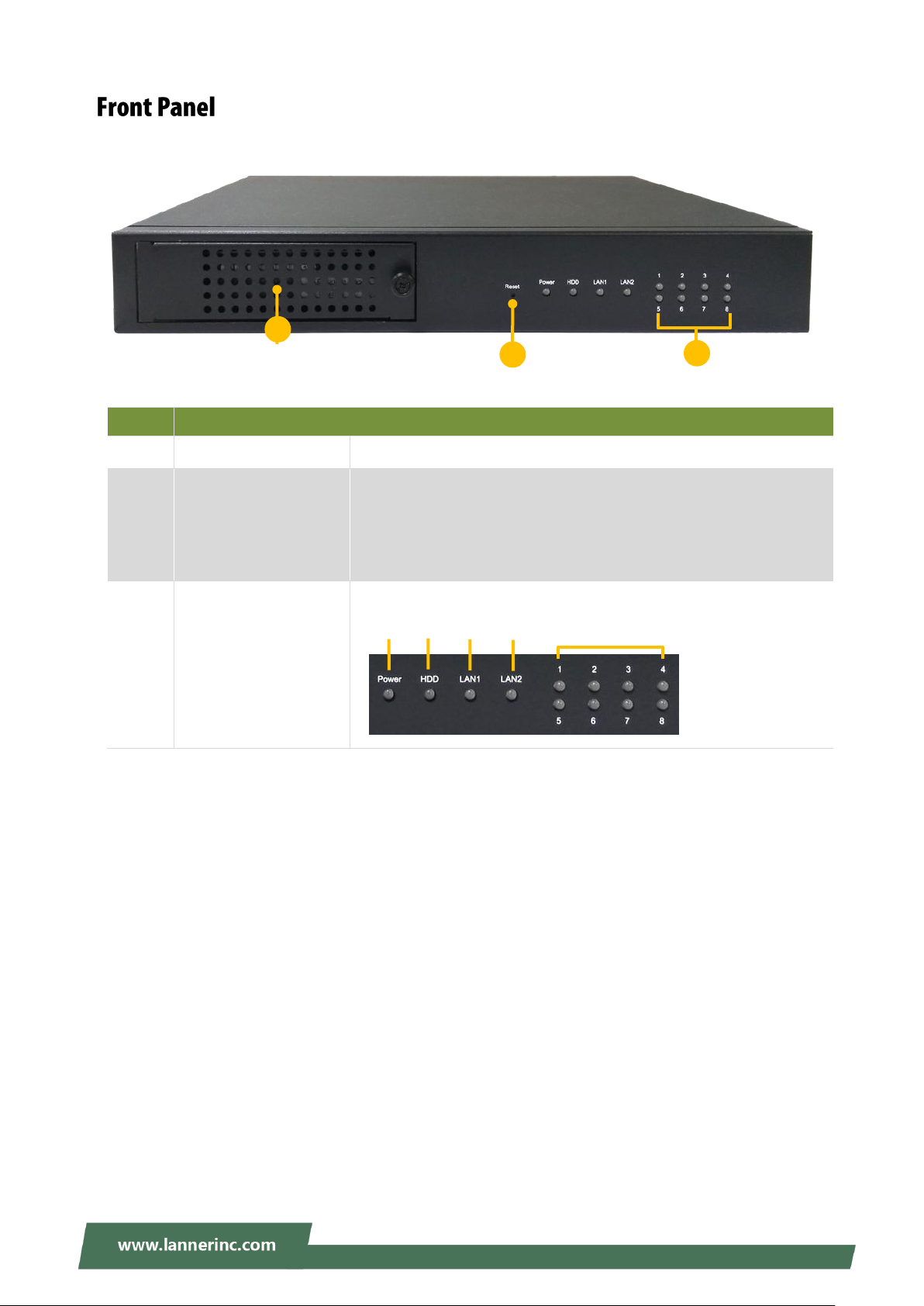
No.
F1
Hard Disk Tray
A hard disk tray to hold a 3.5” HDD
F2
Reset Button
Short-press (<1 sec) to start a system reset
Long-press (>10 sec) to start a system reset with recovery mode
For the recovery mode to be started, make sure the Linux driver
for this GPIO setting is provided.
F3
LED Indicators
F3
Power
Status
HDD
Status
LAN1
Status
LAN2
Status
PoE Port 1~8
Status
F2
F1
11
Page 12

NVA-3000 User Manual
No.
Description
R1
USB Port
2x USB 3.0 ports
R2
GbE Port
2x 10/100/1000Mbps Ethernet ports
R3
PoE Port
8x 10/100Mbos PoE+ ports (802.3af/802.3at)
With the support for PoE+ standard, this system can offer the power of more
than 15.4W ( no more than 30W) to 4 connected devices simultaneously.
R4
DIO Connector
2x 8pin terminal block for 4DI/4DO
Make sure the Linux driver for this GPIO setting is provided.
Pinout
R5
Power Supply
54V DC-in Power Jack
R3
R2
R1
R4
R5
12
Page 13
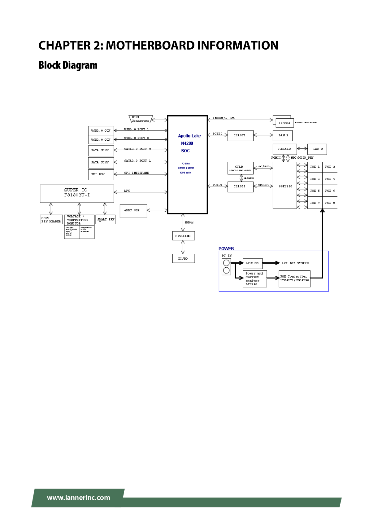
Chapter 2: Motherboard Information
The block diagram indicates how data flows among components on the motherboard. Please refer to the
following figure for your motherboard’s layout design.
13
Page 14
NVA-3000 User Manual
Control Keys
Description
select a setup screen
select an item/option on a setup screen
<Enter>
select an item/option or enter a sub-menu
+/-
adjust values for the selected setup item/option
F1
display General Help screen
F2
retrieve previous values, such as the last configured parameters during the last
time you entered BIOS
F3
load optimized default values
F4
save configurations and exit BIOS
<Esc>
exit the current screen
BIOS is a firmware embedded on an exclusive chip on the system’s motherboard. Lanner's BIOS firmware
offering including market-proven technologies such as Secure Boot and Intel Boot Guard technology
deliver solid commitments for the shield protection against malware, uncertified sequences and other
named cyber threats. BIOS update for Dell PCs are available for download at
http://www.lannerinc.com/products/firmware-and-software/securityenhanced-bios
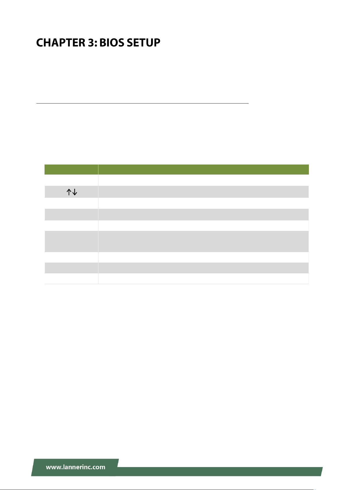
To enter the BIOS setup utility, simply follow the steps below:
1. Boot up the system.
2. Pressing the <Tab> or <Del> key immediately allows you to enter the Setup utility, then you will be
directed to the BIOS main screen. The instructions for BIOS navigations are as below:
14
Page 15

Chapter 3: BIOS Setup
Feature
Description
BIOS
Information
BIOS Vendor: American Megatrends
Core Version: AMI Kernel version, CRB code base, X64
Compliancy: UEFI version, PI version
Project Version: BIOS release version
Build Date and Time: MM/DD/YYYY
Access Level: Administrator / User
System Date
To set the Date, use <Tab> to switch between Date elements. Default
Range of Year: 2005-2099
Default Range of Month: 1-12
Days: dependent on Month.
System Time
To set the Date, use <Tab> to switch between Date elements.
Setup main page contains BIOS information and project version information.
15
Page 16
NVA-3000 User Manual
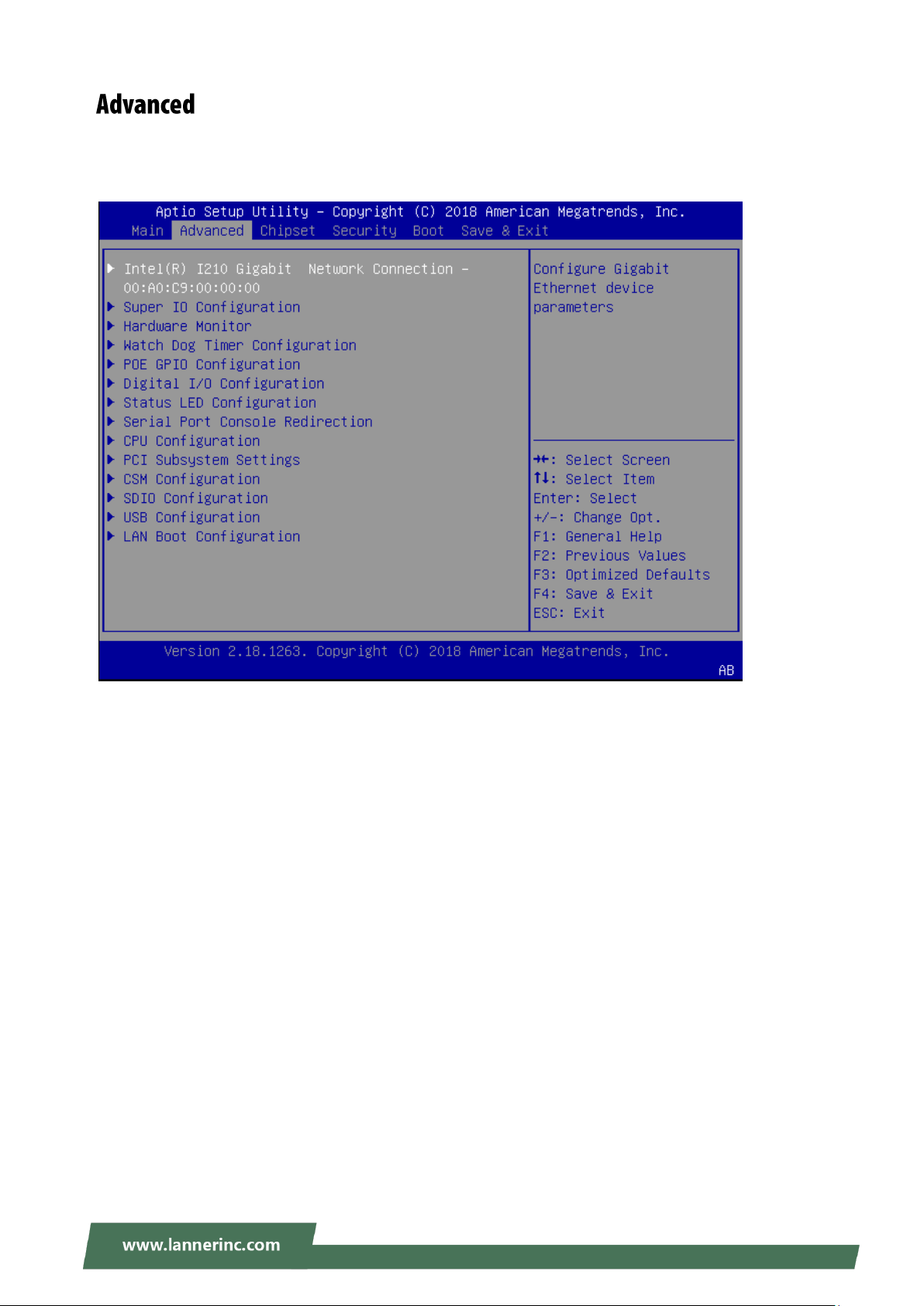
Select the Advanced menu item from the BIOS setup screen to enter the “Advanced” setup screen. Users
can select any of the items in the left frame of the screen.
16
Page 17
Chapter 3: BIOS Setup
17
Page 18
NVA-3000 User Manual
Feature
Options
Description
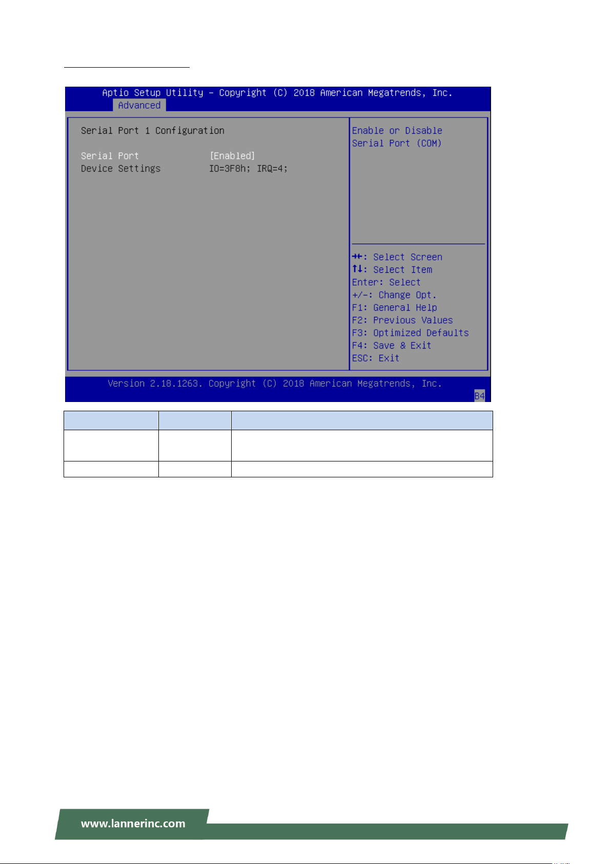
Serial Port
Enabled
Disabled
Enables or disables Serial Port 1.
Device Settings
NA
IO=3F8h; IRQ = 4
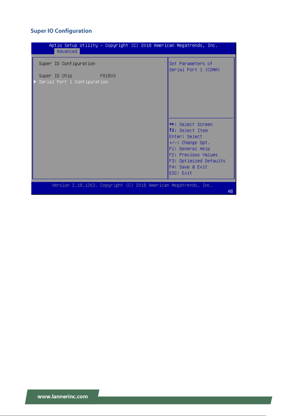
Serial port 1 Configuration
18
Page 19
Chapter 3: BIOS Setup
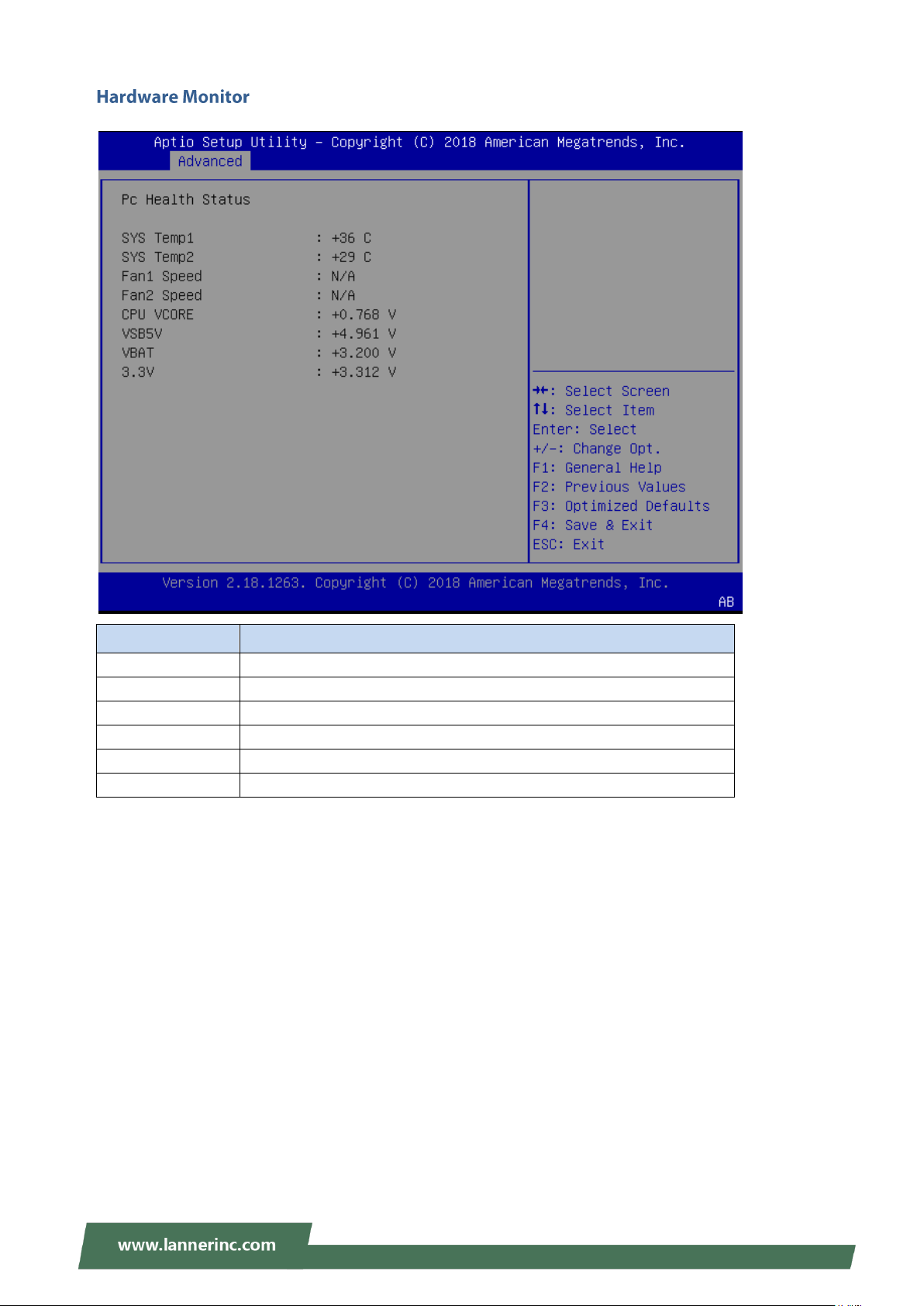
Feature
Description
CPU Temp
This value reports the CPU temperature.
SYS Temp
This value reports the System temperature.
CPU VCORE
This value reports the CPU VCORE.
VSB5V
This value reports the VSB5V Input voltage.
VBAT
This value reports the VBAT Input voltage.
3.3V
This value reports the 3.3V Input voltage.
19
Page 20
NVA-3000 User Manual
Feature
Options
Description
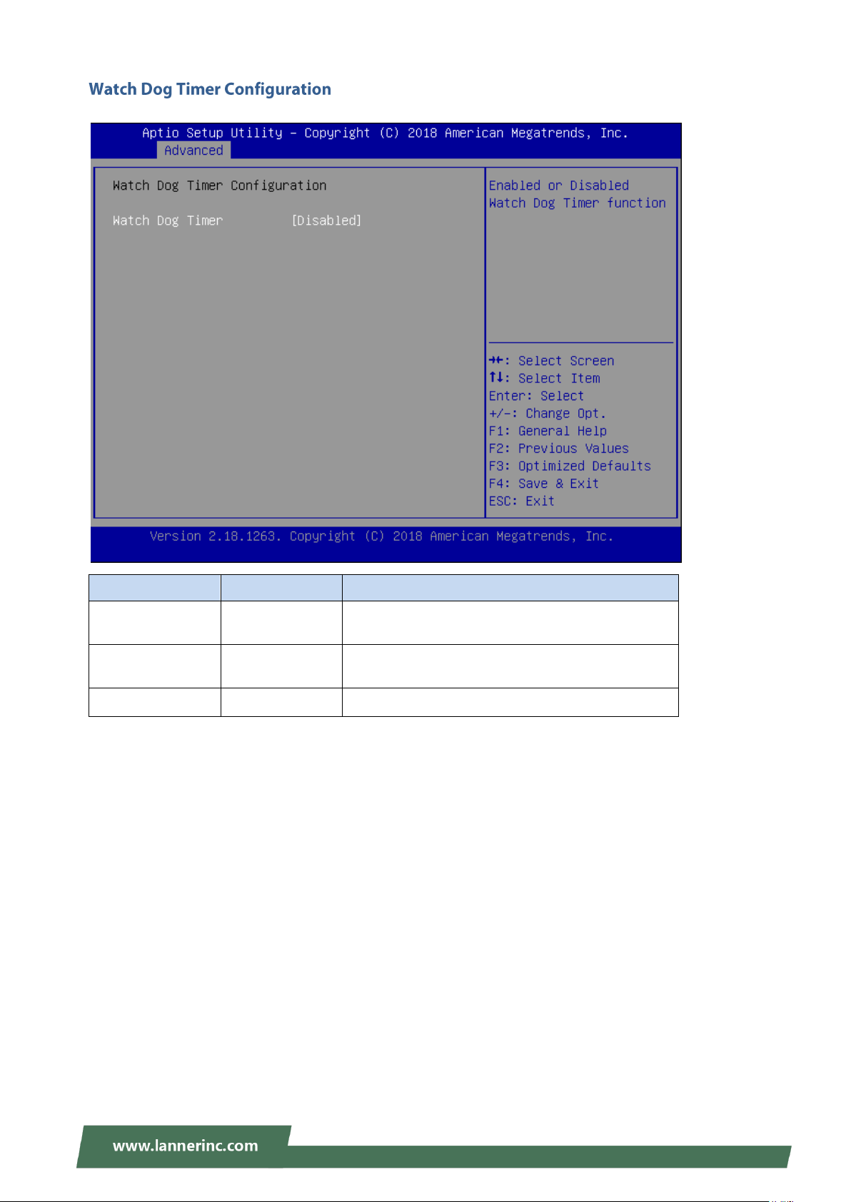
Watch Dog Timer
Enabled
Disabled
Enable or Disable Watch Dog function
Timer Count
Mode
Second Mode
Minute Mode
Select Second Mode or Minute Mode
Timer out Value
60
Watch Dog Timer out Value 0-255
20
Page 21
Chapter 3: BIOS Setup
Feature
Options
Description
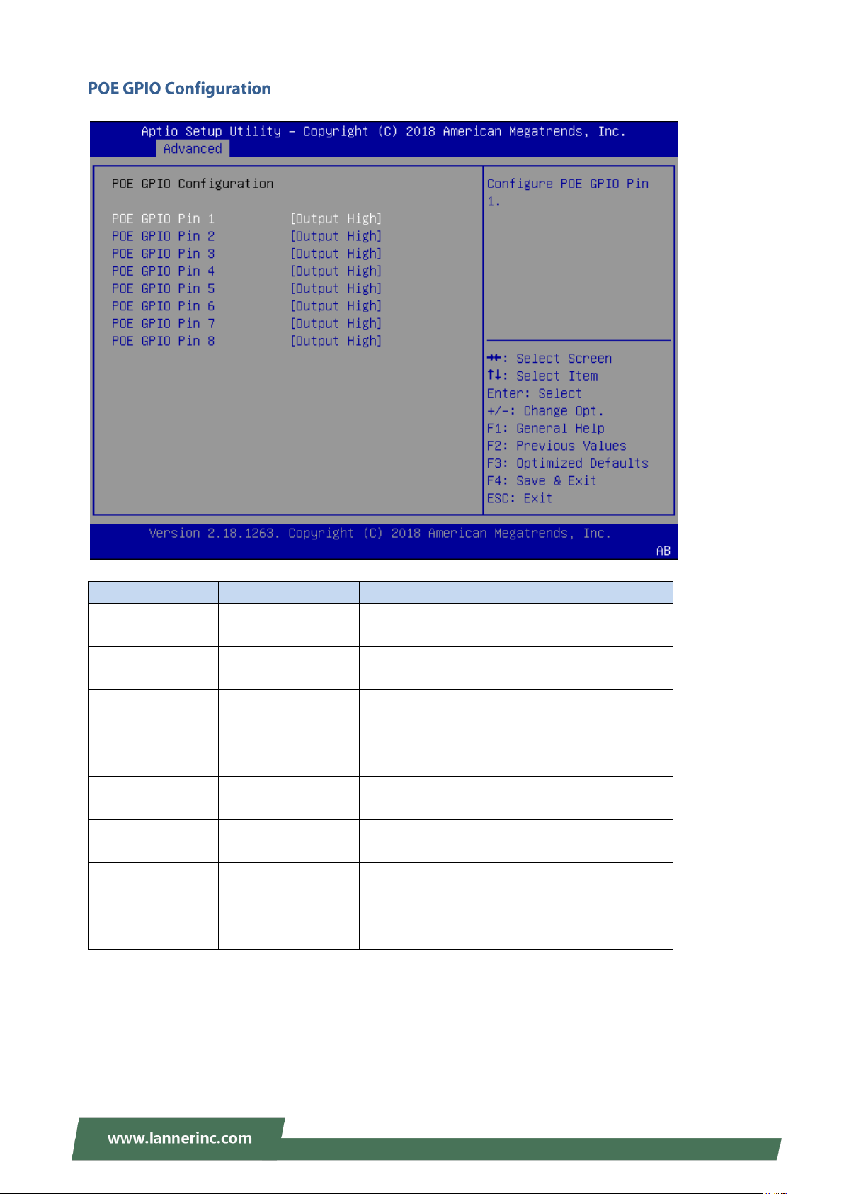
POE GPIO Pin 1
Output Low
Output High
Configure POE GPIO Pin 1.
POE GPIO Pin 2
Output Low
Output High
Configure POE GPIO Pin 2.
POE GPIO Pin 3
Output Low
Output High
Configure POE GPIO Pin 3.
POE GPIO Pin 4
Output Low
Output High
Configure POE GPIO Pin 4.
POE GPIO Pin 5
Output Low
Output High
Configure POE GPIO Pin 5
POE GPIO Pin 6
Output Low
Output High
Configure POE GPIO Pin 6.
POE GPIO Pin 7
Output Low
Output High
Configure POE GPIO Pin 7.
POE GPIO Pin 8
Output Low
Output High
Configure POE GPIO Pin 8.
21
Page 22
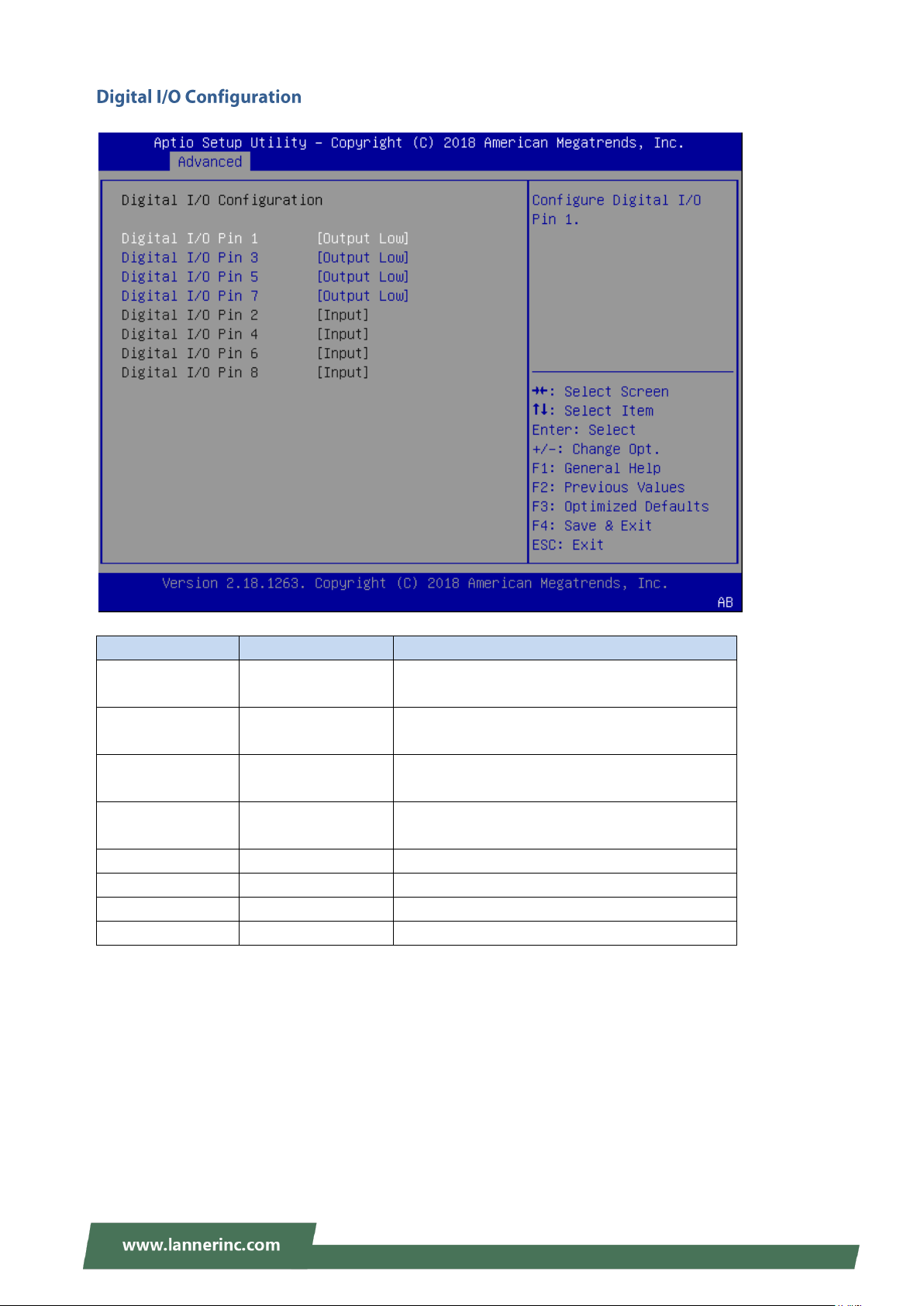
NVA-3000 User Manual
Feature
Options
Description
Digital I/O Pin 1
Output Low
Output High
Configure Digital I/O Pin 1.
Digital I/O Pin 2
Output Low
Output High
Configure Digital I/O Pin 2.
Digital I/O Pin 3
Output Low
Output High
Configure Digital I/O Pin 3.
Digital I/O Pin 4
Output Low
Output High
Configure Digital I/O Pin 4.
POE GPIO Pin 5
Input
Configure Digital I/O Pin 5.
POE GPIO Pin 6
Input
Configure Digital I/O Pin 6.
POE GPIO Pin 7
Input
Configure Digital I/O Pin 7.
POE GPIO Pin 8
Input
Configure Digital I/O Pin 8.
22
Page 23
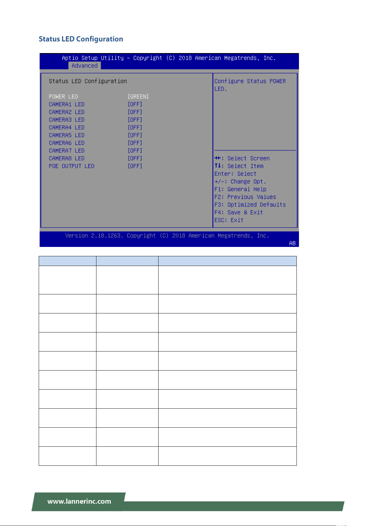
Chapter 3: BIOS Setup
Feature
Options
Description
Power LED
OFF
ORANGE
GREEN
Configure Status POWER LED.
CAMERA1 LED
OFF
ORANGE
Configure CAMERA1 LED .
CAMERA2 LED
OFF
ORANGE
Configure CAMERA2 LED.
CAMERA3 LED
OFF
ORANGE
Configure CAMERA3 LED .
CAMERA4 LED
OFF
ORANGE
Configure CAMERA4 LED.
CAMERA5 LED
OFF
ORANGE
Configure CAMERA5 LED .
CAMERA6 LED
OFF
ORANGE
Configure CAMERA6 LED.
CAMERA7 LED
OFF
ORANGE
Configure CAMERA7 LED.
CAMERA8 LED
OFF
ORANGE
Configure CAMERA8 LED.
POE OUTPUT LED
OFF
ORANGE
Configure OUTPUT LED.
23
Page 24
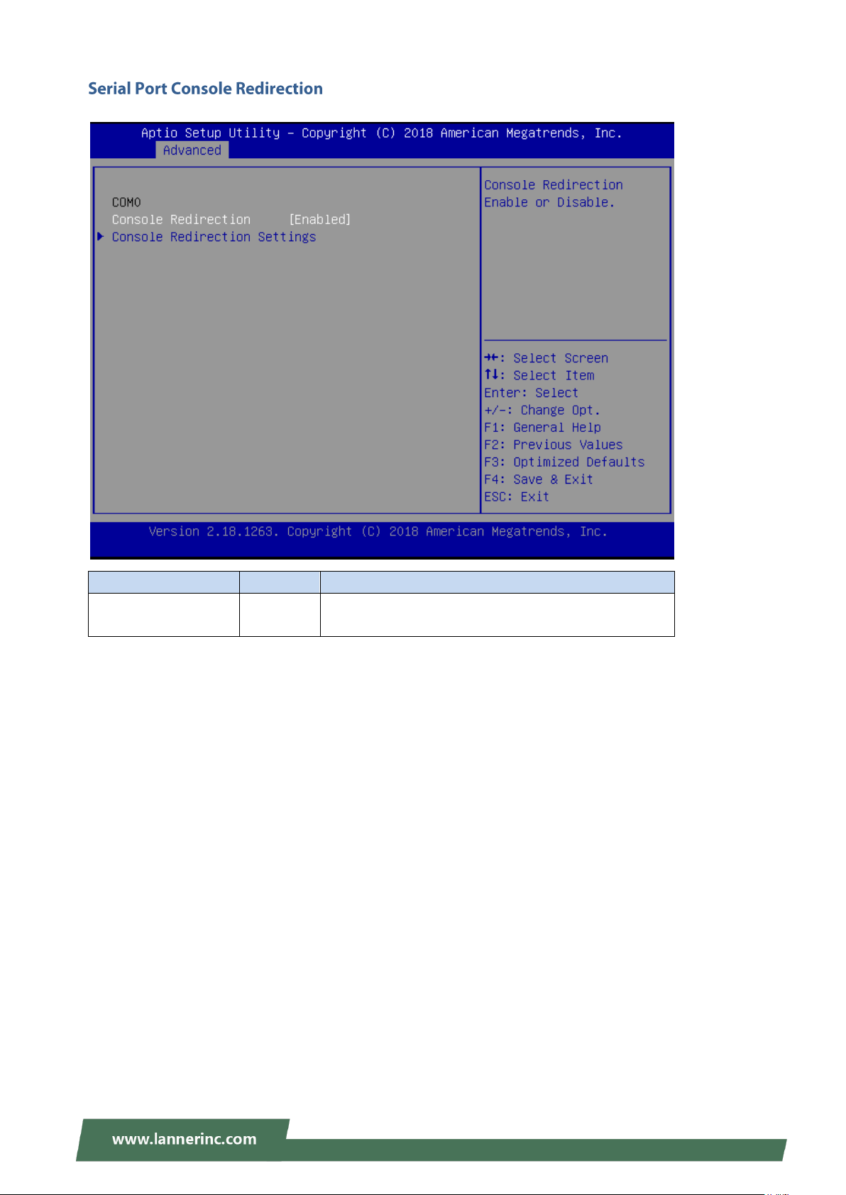
NVA-3000 User Manual
Feature
Options
Description
COM0
Console Redirection
Enabled
Disabled
Console Redirection Enable or Disable.
24
Page 25
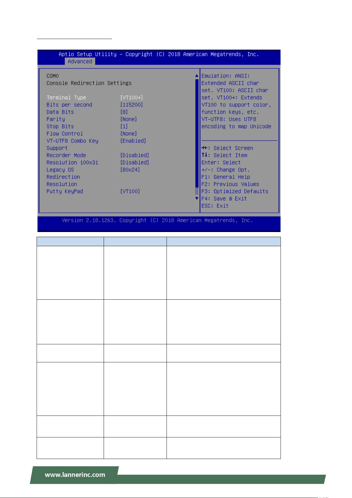
Chapter 3: BIOS Setup
Feature
Options
Description
Terminal Type
VT100
VT100+
VT-UTF8
ANSI
ANSI: Extended ASCII char set.
VT100: ASCII char set.
VT100+: Extends VT100 to support color,
function keys, etc.
VT-UTF8: Uses UTF8 encoding to map
Unicode chars onto 1 or more bytes.
Bits per second
9600
19200
38400
57600
115200
Selects serial port transmission speed.
The speed must be matched on the other
side. Long or noisy lines may require
lower speeds.
Data Bits
7
8
Data Bits
Parity
None
Even
Odd
Mark
Space
A parity bit can be sent with the data bits
to detect some transmission errors.
Stop Bits
1
2
Stop bits indicate the end of a serial data
packet.
Flow Control
None
Hardware RTS/CTS
Flow control can prevent data loss from
buffer overflow.
Console Redirection Setting
25
Page 26

NVA-3000 User Manual
VT-UTF8 Combo Key
Support
Disabled
Enabled
Enable VT-UTF8 Combination Key
Support for ANSI/VT100 terminals
Recorder Mode
Disabled
Enabled
With this mode enabled only text will be
sent. This is to capture Terminal data.
Resolution 100x31
Disabled
Enabled
Enables or disables extended terminal
resolution.
Legacy OS Redirection
Resolution
80x24
80x25
On Legacy OS, the Number of Rows and
Columns supported redirection.
Putty KeyPad
VT100
LINUX
XTERM86
SCO
ESCN
VT400
Select FunctionKey and KeyPad on Putty.
Redirection After BIOS
POST
Always Enable
BootLoader
When Bootloader is selected, then
Legacy Console Redirection is disabled
before booting to legacy OS. When
Always Enable is selected, then Legacy
Console Redirection is enabled for legacy
OS. Default setting for this option is set
to Always Enable.
26
Page 27
Chapter 3: BIOS Setup
Feature
Options
Description
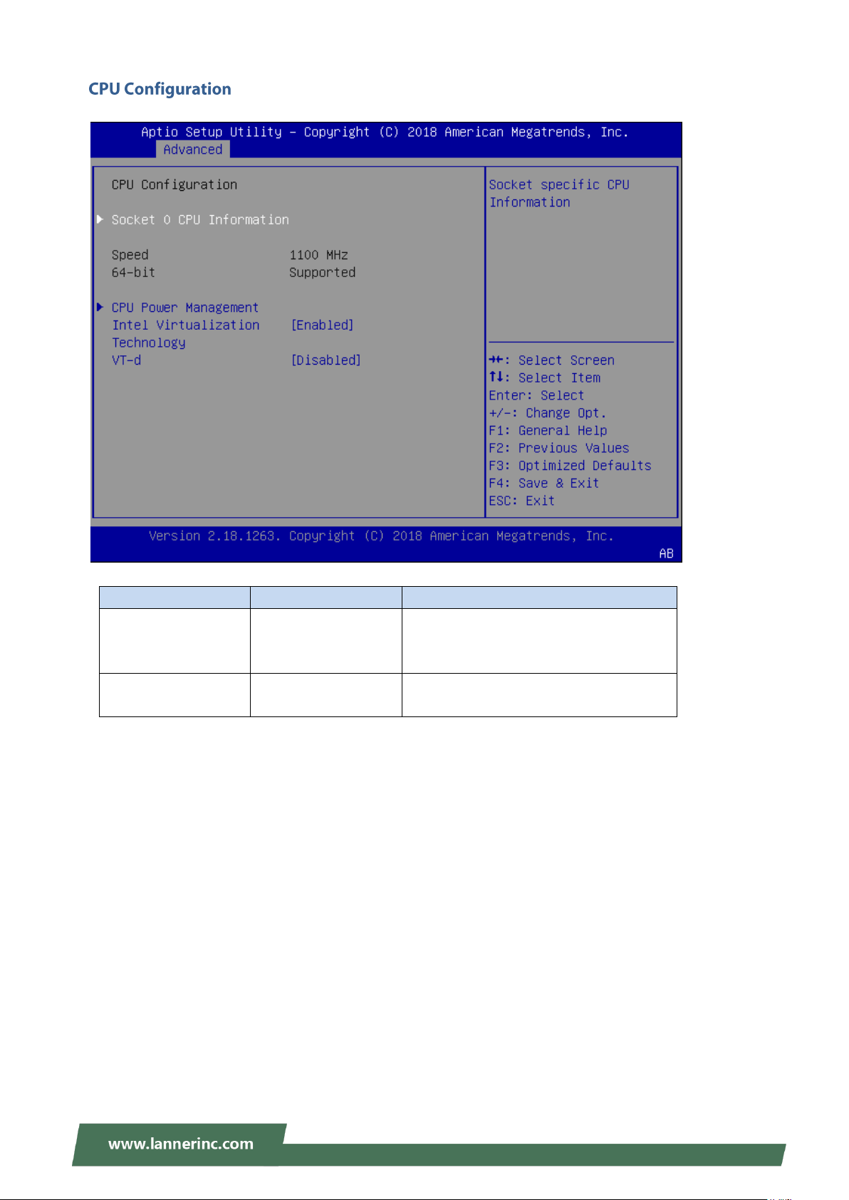
Intel Virtualization
Technology
Disabled
Enabled
When enabled, a VMM can utilize the
additional hardware capabilities provided
by Vanderpool Technology
VT-d
Disabled
Enabled
Enable/Disable CPU VT-d
27
Page 28
NVA-3000 User Manual
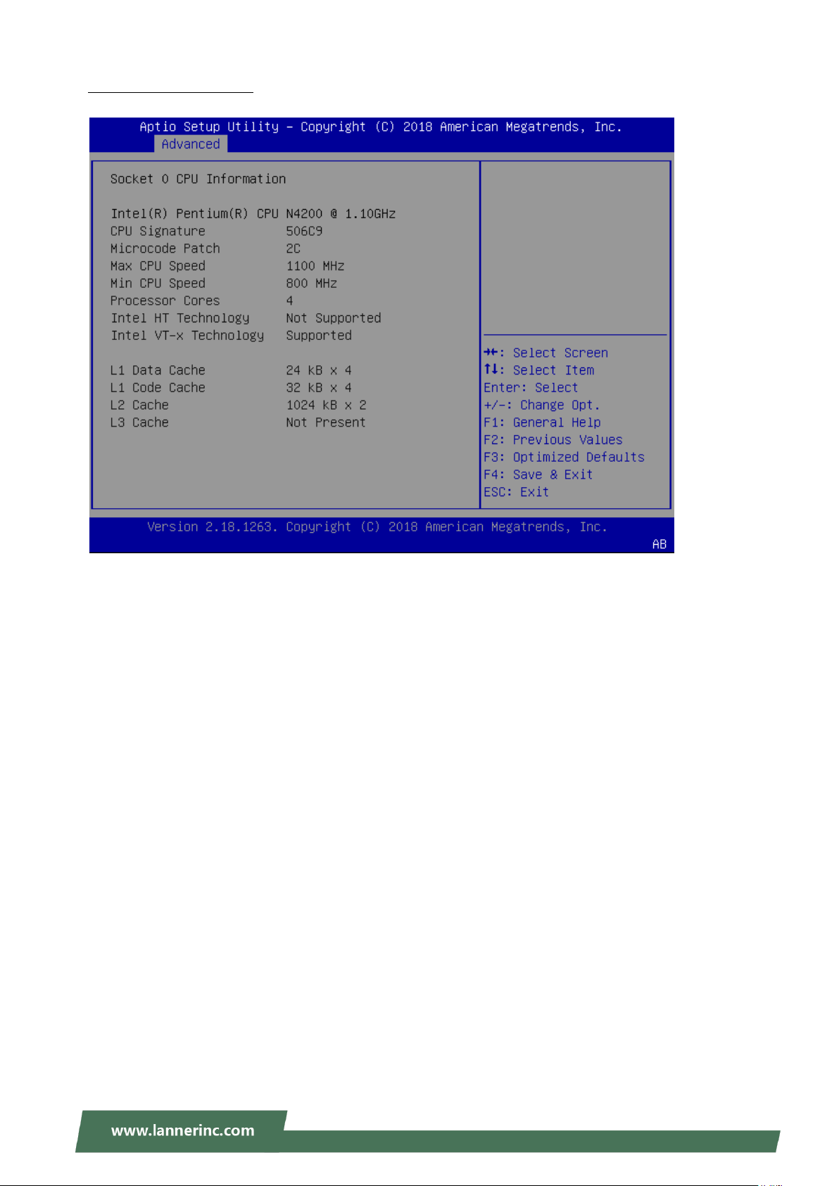
Socket 0 CPU Information
28
Page 29
Chapter 3: BIOS Setup
Feature
Options
Description
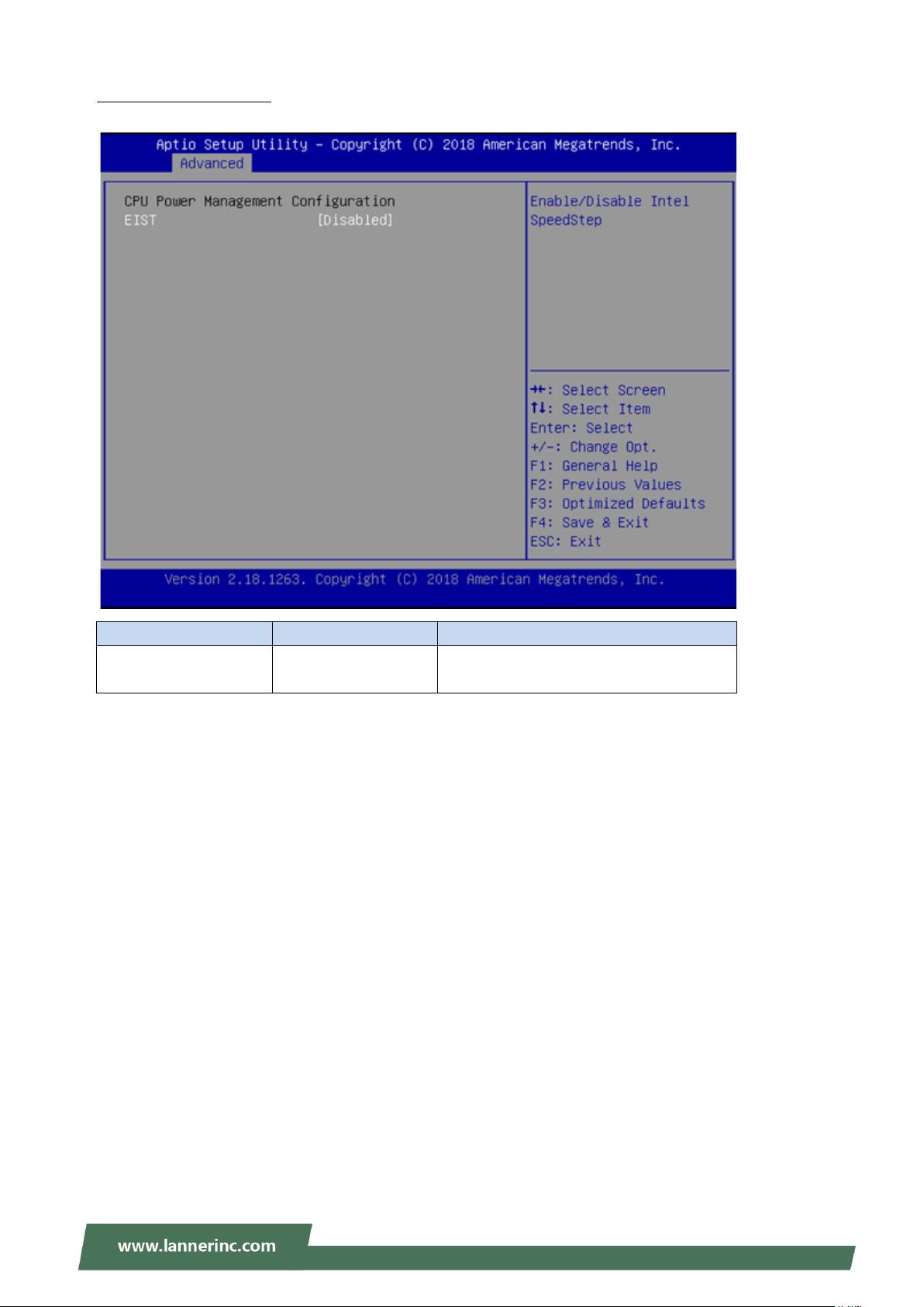
EIST
Disabled
Enabled
Enable/Disable Intel SpeedStep
CPU Power Management
29
Page 30
NVA-3000 User Manual
Feature
Options
Description
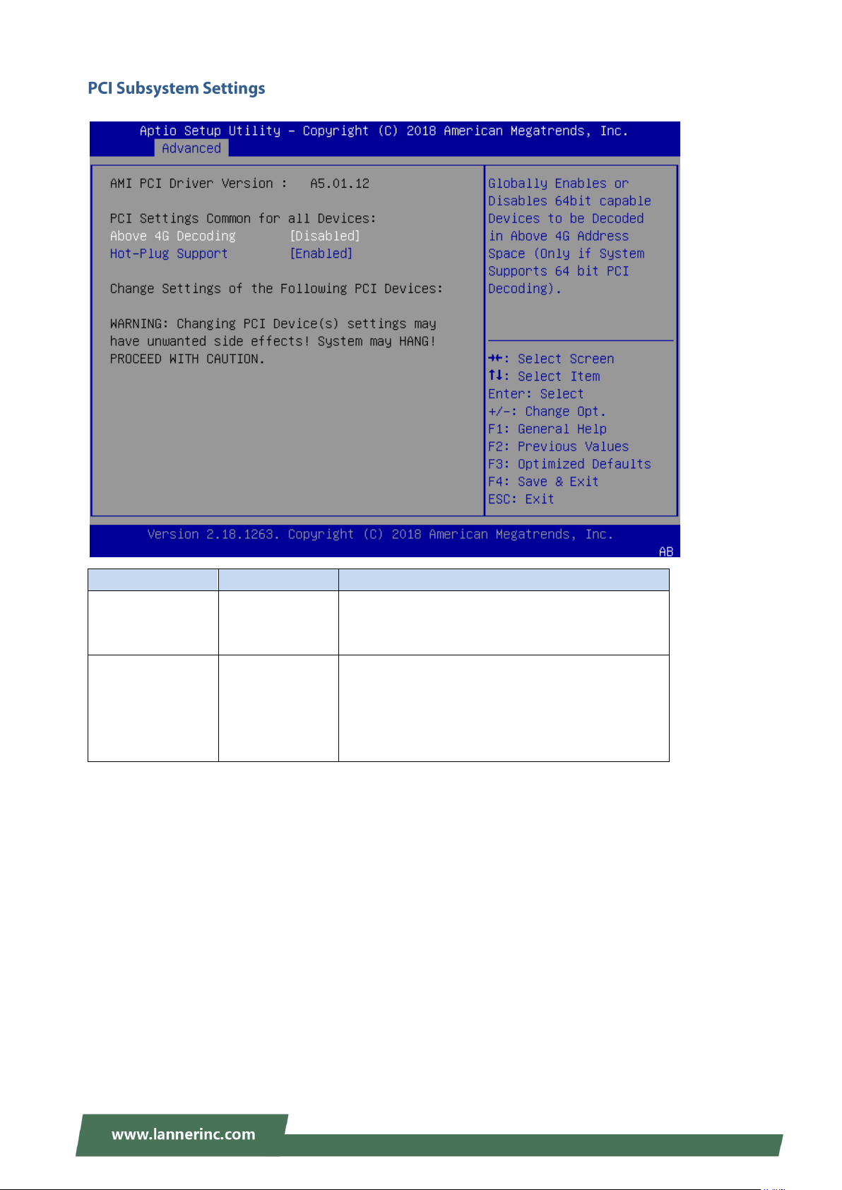
Above 4G
Decoding
Disabled
Enabled
Globally Enables or Disables 64bit capable Devices
to be Decoded in Above 4G Address Space (Only if
System Supports 64 bit PCI Decoding).
Hot-Plug Support
Enabled
Disabled
Globally Enables or Disables Hot-Plug support for
the entire System. If System has Hot-Plug capable
Slots and this option set to Enabled, it provides a
Setup screen for selecting PCI resource padding
for Hot-Plug.
30
Page 31
Chapter 3: BIOS Setup
Feature
Options
Description
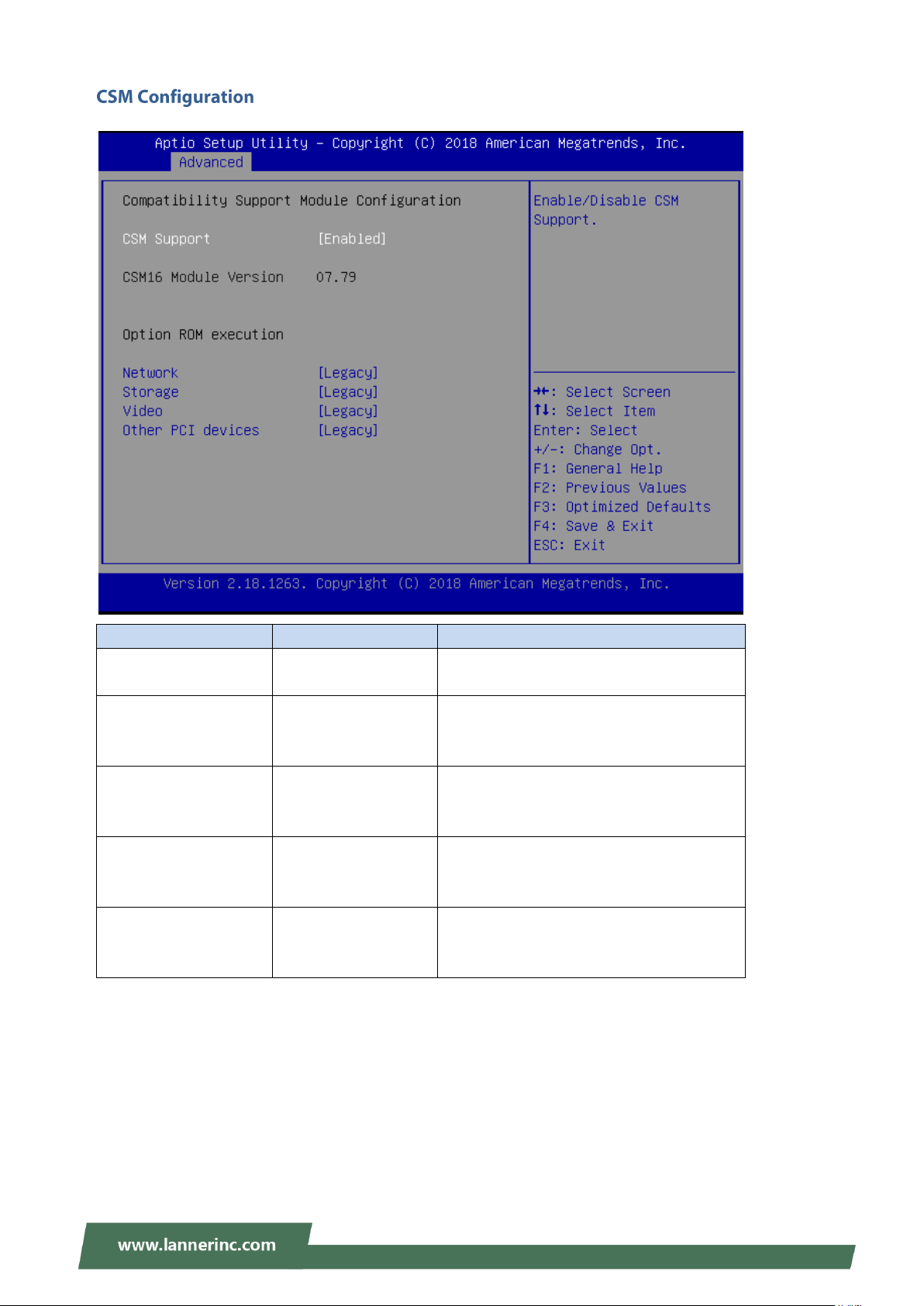
CSM Support
Disabled
Enabled
Enables or disables CSM Support
Network
Do Not Launch
UEFI
Legacy
Controls the execution of UEFI and Legacy
PXE OpROM
Storage
Do Not Launch
UEFI
Legacy
Controls the execution of UEFI and Legacy
Storage OpROM
Video
Do Not Launch
UEFI
Legacy
Controls the execution of UEFI and Legacy
Video OpROM
Other PCI device
Do Not Launch
UEFI
Legacy
Determines OpROM execution policy for
devices other than Network, Storage, or
Video
31
Page 32
NVA-3000 User Manual
Feature
Options
Description
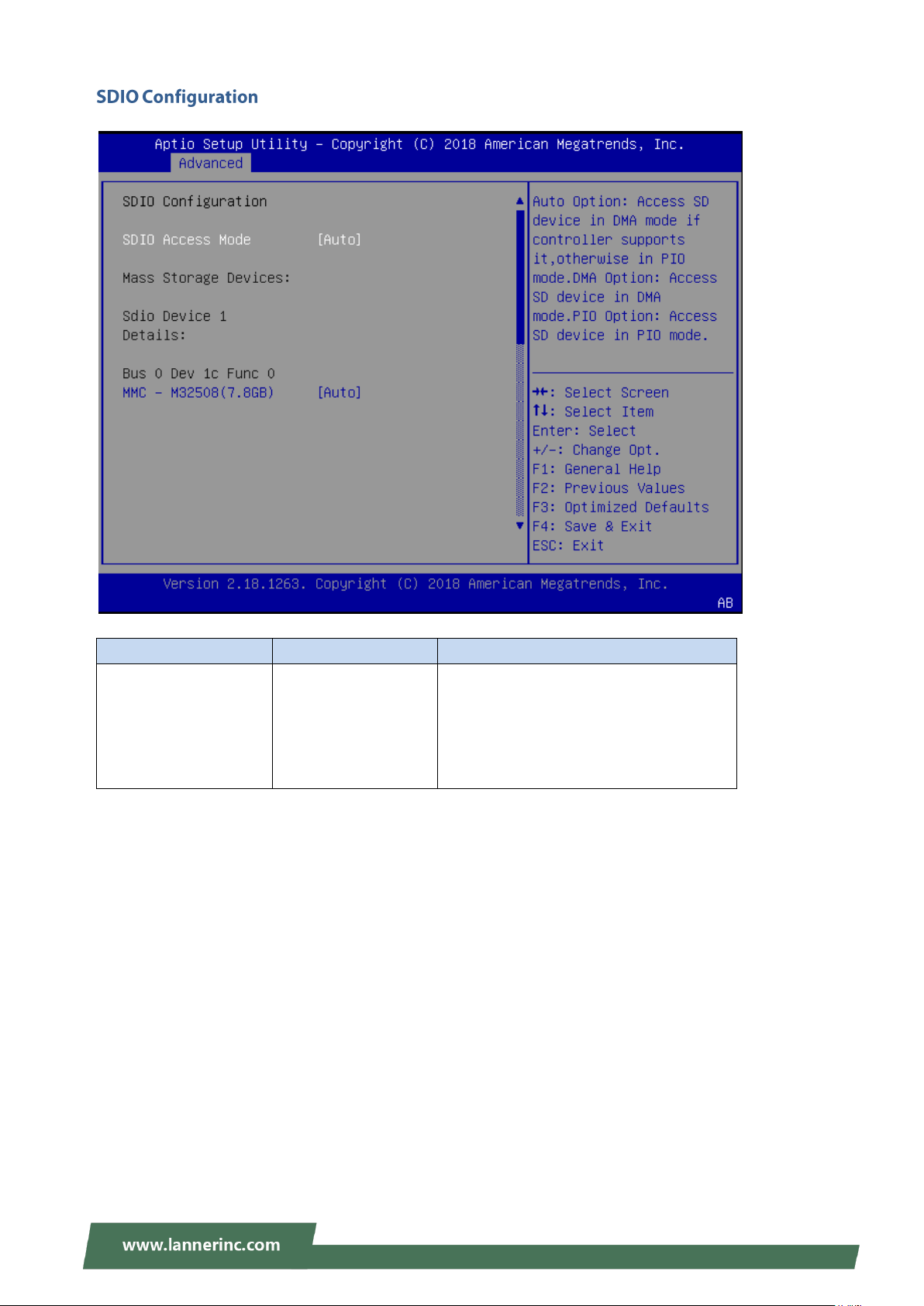
SDIO Access Mode
AUTO
ADMA
SDMA
PIO
Auto: Access SD device in DMA mode if
controller supports it, otherwise in PIO
mode.
DMA: Access SD device in DMA mode.
PIO: Access SD device in PIO mode.
32
Page 33
Chapter 3: BIOS Setup
Feature
Options
Description
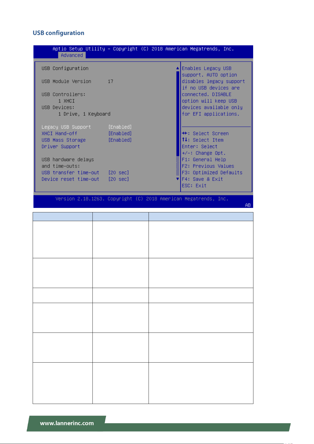
Legacy USB Support
Enabled
Disabled
Auto
Enables Legacy USB support.
Auto option disables legacy support if no
USB devices are connected;
Disabled option will keep USB devices
available only for EFI applications.
XHCI Hand-off
Enabled
Disabled
This is a workaround for OSes without
XHCI hand-off support. The XHCI
ownership change should be claimed by
XHCI driver.
USB Mass Storage
Driver Support
Enabled
Disabled
Enables or disables USB Mass Storage
Driver Support.
USB transfer time-out
1 sec
5 sec
10 sec
20 sec
The time-out value for Control, Bulk, and
Interrupt transfers
Device reset time-out
1 sec
5 sec
10 sec
20 sec
USB mass storage device Start Unit
command time-out
Device power-up delay
Auto
Manual
Maximum time the device will take before
it properly reports itself to the Host
Controller. Auto uses default value: for a
Root port, it is 100 ms, for a Hub port the
delay is taken from Hub descriptor.
33
Page 34
NVA-3000 User Manual
Feature
Options
Description
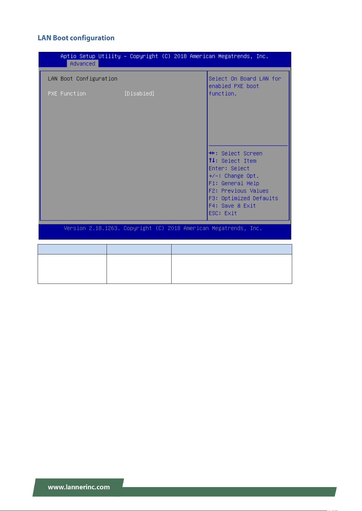
PXE Function
Disabled
LAN1
LAN2
Select On Board LAN for enabled PXE boot
function.
34
Page 35
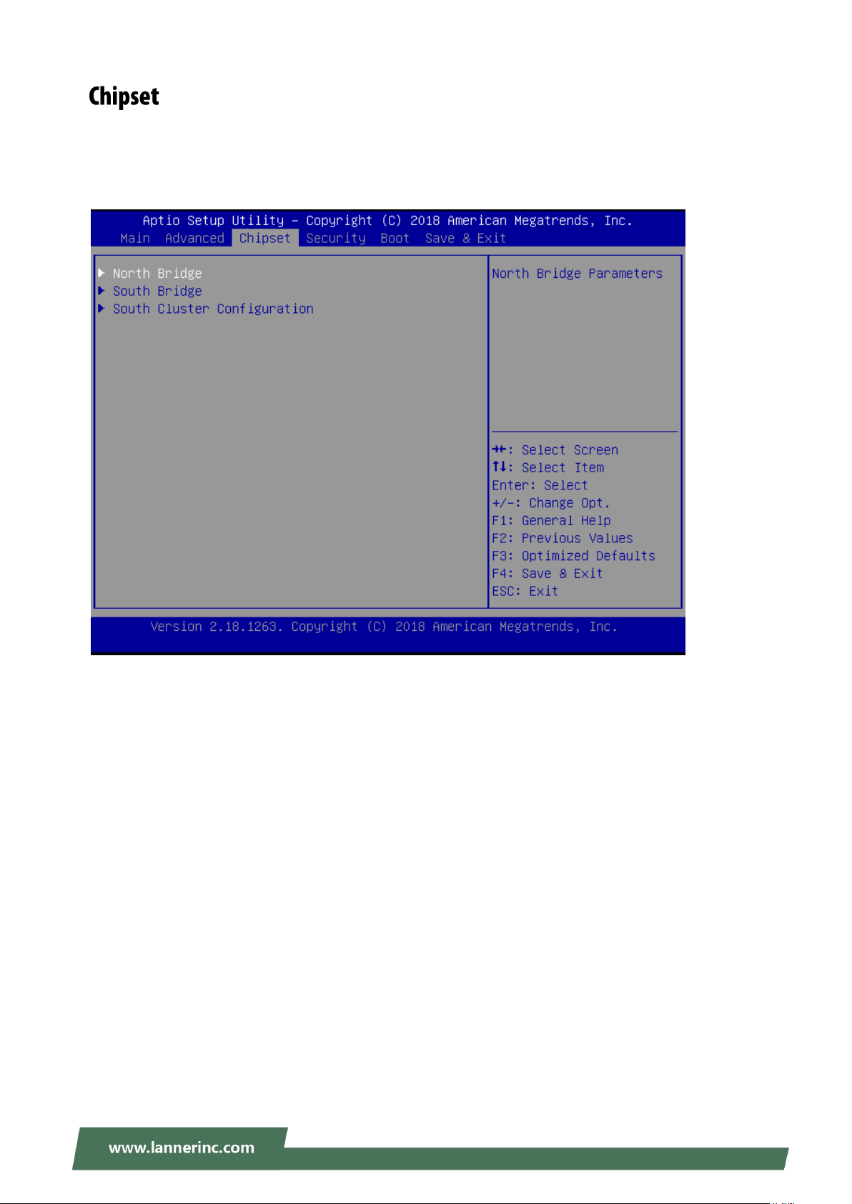
Chapter 3: BIOS Setup
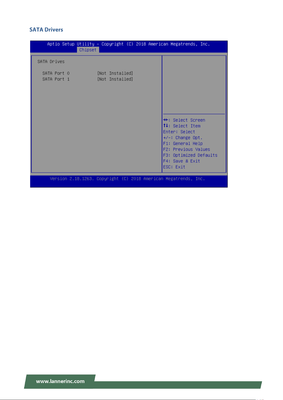
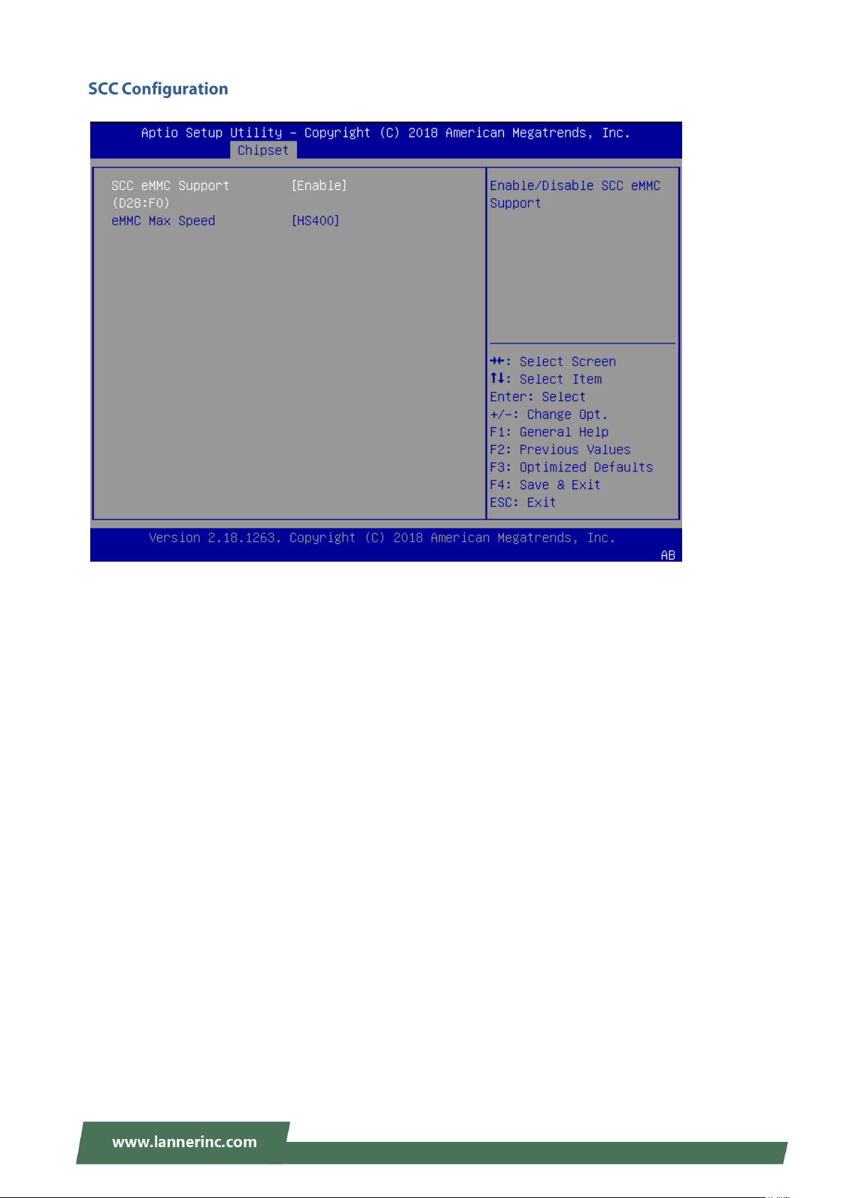
Select the Chipset menu item from the BIOS setup screen to enter the “Chipset” setup screen. Users can
select any of the items in the left frame of the screen.
35
Page 36
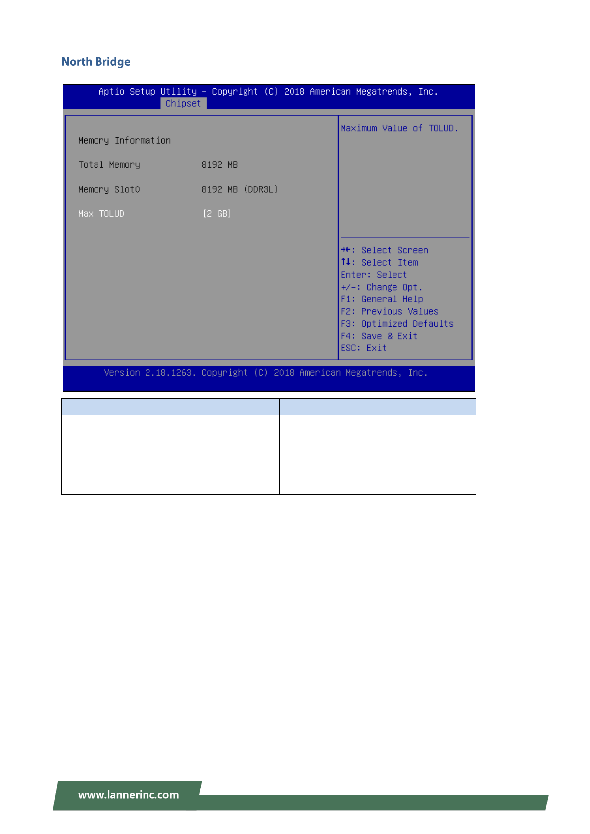
NVA-3000 User Manual
Feature
Options
Description
Max TOLUD
2 GB
2.25 GB
2.5 GB
2.75 GB
3 GB
Maximum Value of TOLUD.
36
Page 37
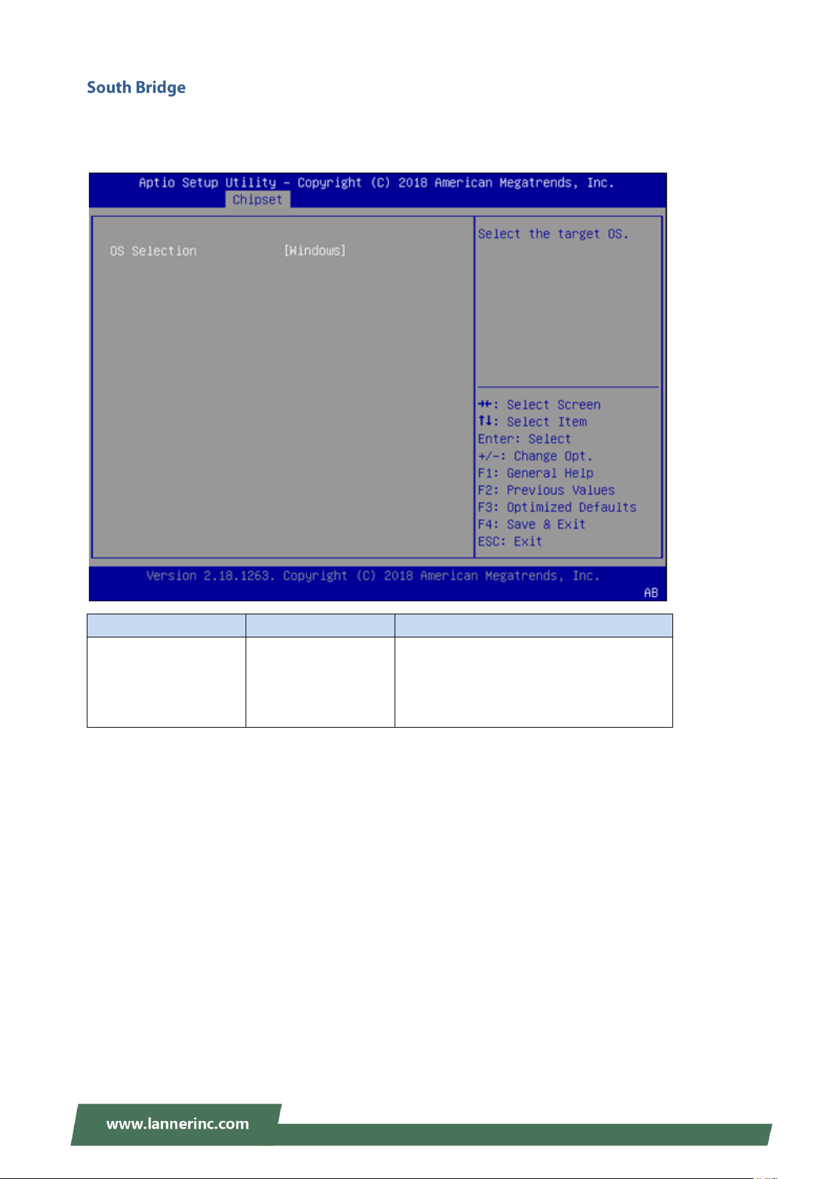
Chapter 3: BIOS Setup
Feature
Options
Description
OS Selection
Windows
Android
Win7
Intel Linux
Select the target OS
The OS Selection setting is linked to the status of CSM Support under Advanced > CSM Configuration.
Please make sure you select the right option based on the OS used.
37
Page 38
NVA-3000 User Manual
38
Page 39
Chapter 3: BIOS Setup
39
Page 40
NVA-3000 User Manual
40
Page 41
Chapter 3: BIOS Setup
Feature
Description
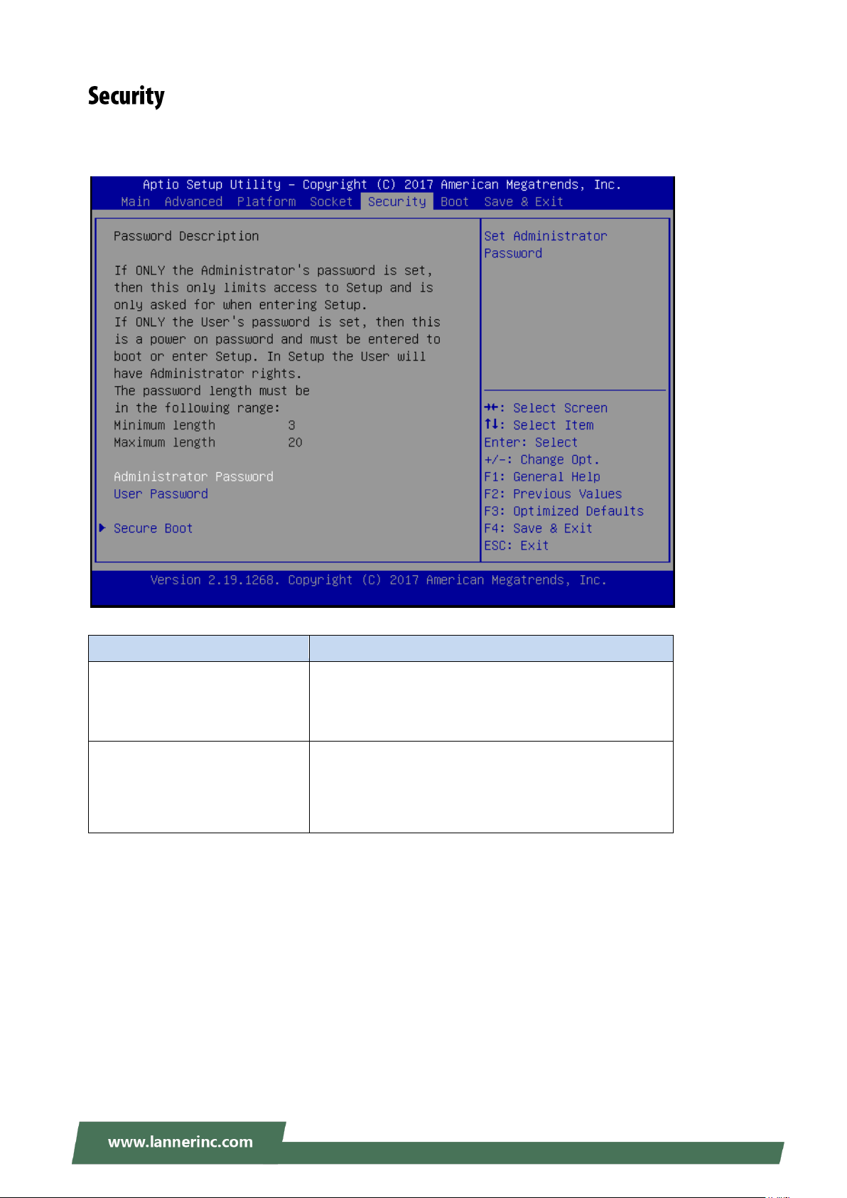
Administrator Password
If ONLY the Administrator's password is set, it only
limits access to Setup and is only asked for when
entering Setup.
User Password
If ONLY the User's password is set, it serves as a
power-on password and must be entered to boot or
enter Setup. In Setup, the User will have Administrator
rights.
Select the Security menu item from the BIOS setup screen to enter the Security Setup screen. Users can
select any of the items in the left frame of the screen.
41
Page 42
NVA-3000 User Manual
Feature
Options
Description
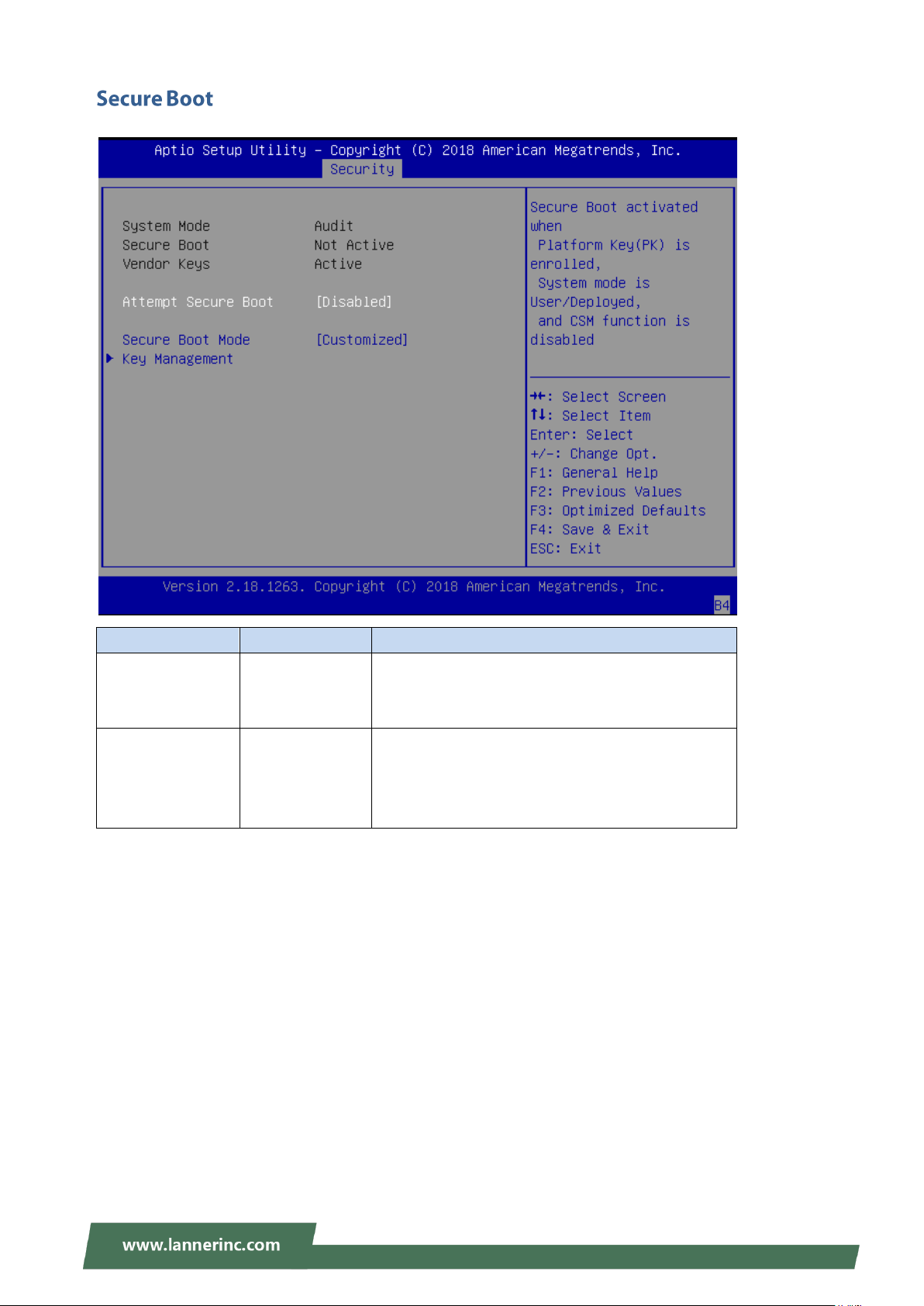
Attempt Secure
Boot
Disabled
Enabled
Secure Boot is activated when Platform Key(PK) is
enrolled, System mode is User/Deployed, and CSM
function is disabled.
Secure Boot Mode
Standard
Customized
Customizable Secure Boot mode: In Custom mode,
Secure Boot Policy variables can be configured by
a physically present user without full
authentication.
42
Page 43
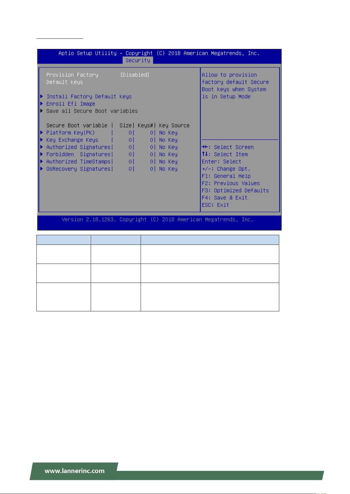
Chapter 3: BIOS Setup
Feature
Options
Description
Provision Factory
Default keys
Disabled
Enabled
Allow to provision factory default Secure Boot keys
when System is in Setup Mode
Install Factory
Default keys
None
Force System to User Mode - install all Factory
Default keys
Enroll Efi Image
None
Allow the image to run in Secure Boot mode. Enroll
SHA256 Hash Certificate of the Image into
Authorized Signature Database (db)
Key Management
43
Page 44
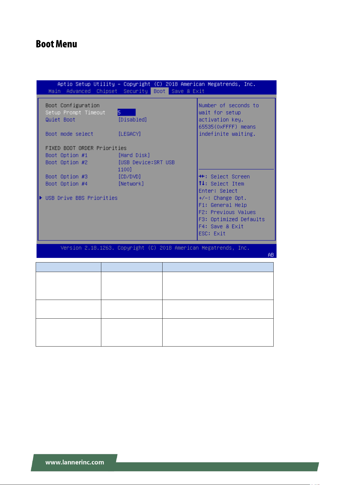
NVA-3000 User Manual
Feature
Options
Description
Setup Prompt Timeout
5
The number of seconds to wait for setup
activation key.
65535 means indefinite waiting.
Quiet Boot
Disabled
Enabled
Enable or disables Quiet Boot option.
Boot mode select
LEGACY
UEFI
DUAL
Select boot mode for LEGACY or UEFI.
Select the Boot menu item from the BIOS setup screen to enter the Boot Setup screen. Users can select any
of the items in the left frame of the screen.
Choose boot priority from boot option group.
Choose specifies boot device priority sequence from available Group device.
44
Page 45
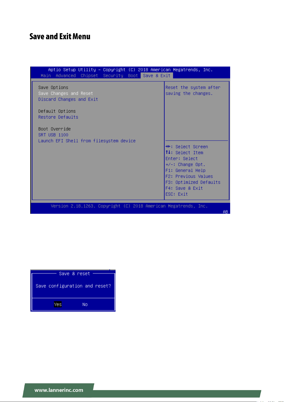
Select the Save and Exit menu item from the BIOS setup screen to enter the Save and Exit Setup screen.
Users can select any of the items in the left frame of the screen.
■ Save Changes and Reset
When Users have completed the system configuration changes, select this option to save the changes and
exit from BIOS Setup in order for the new system configuration parameters to take effect. The following
window will appear after selecting the “Save Changes and Exit” option is selected. Select “Yes” to Save
Changes and Exit Setup.
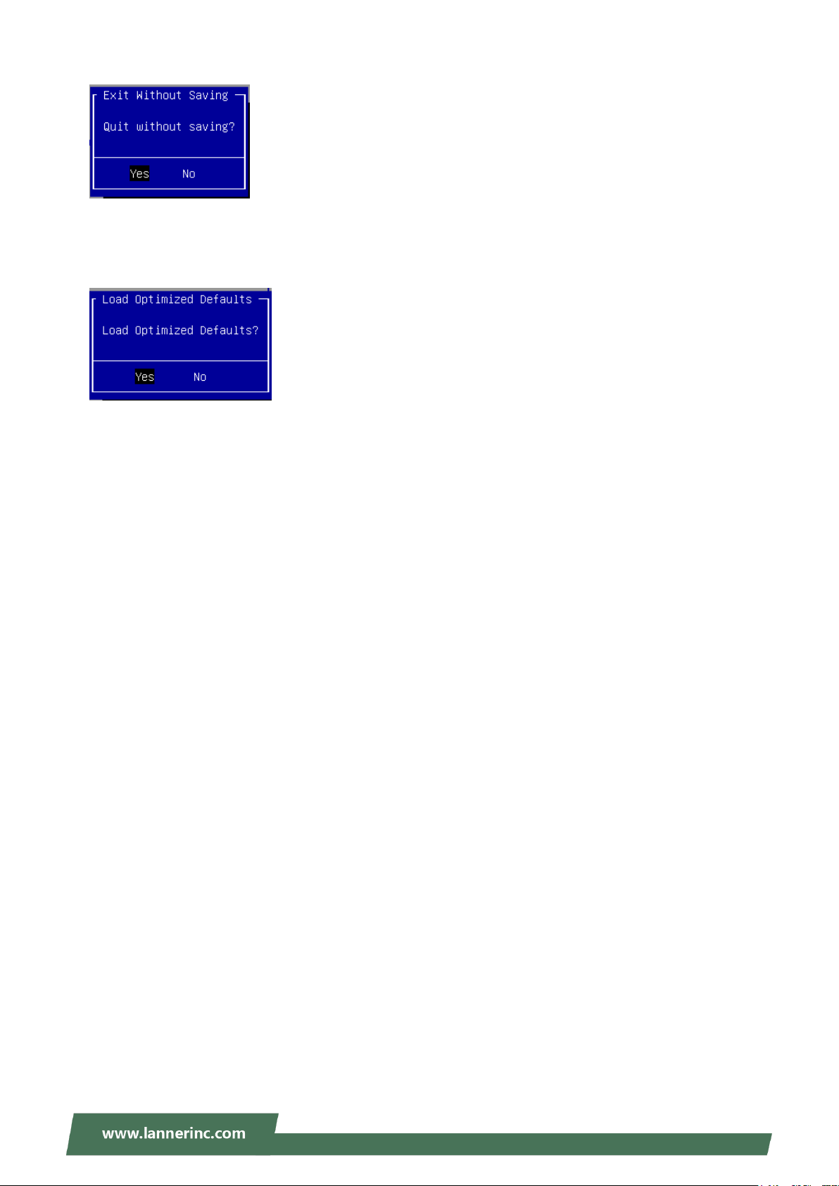
■ Discard Changes and Exit
Select this option to quit Setup without saving any modifications to the system configuration. The following
window will appear after the “Discard Changes and Exit” option is selected. Select “Yes” to Discard changes
and Exit Setup.
45
Page 46
NVA-3000 User Manual
■ Restore Defaults
Restore default values for all setup options. Select “Yes” to load Optimized defaults.
PS: The items under Boot Override were not same with image. It should depend on devices connect on
system.
PS: The items under Boot Override were not same with image. It should depend on devices connect on
system.
46
Page 47
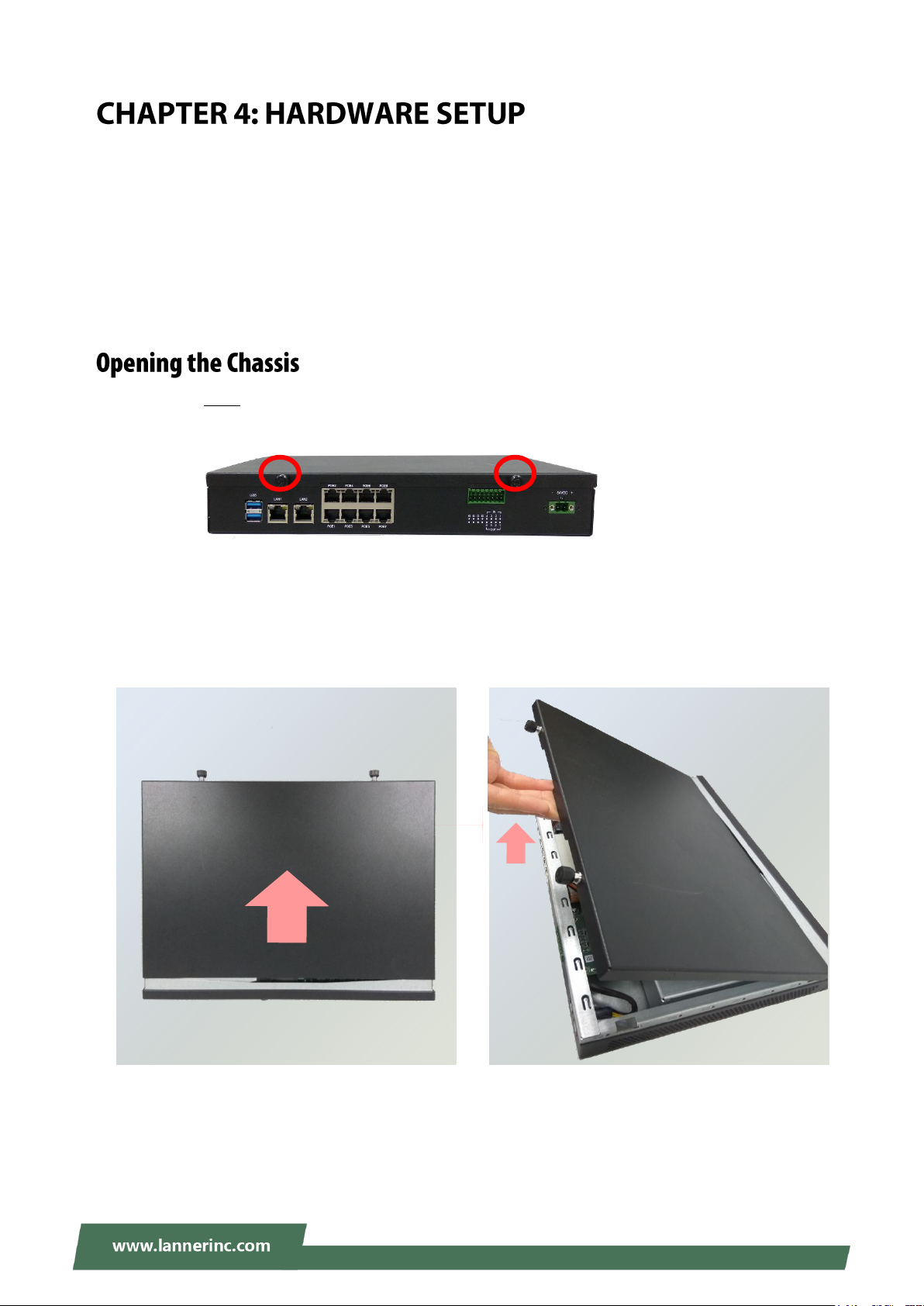
Chapter 4: Hardware Setup
To reduce the risk of personal injury, electric shock, or damage to the equipment, please remove all power
connections to completely shut down the device. Also, please wear ESD protection gloves when conducting
the steps described hereafter.
In light of the motherboard layout arrangement, the installation of the M.2 card, DDR4 memory, and
Wireless module should be prior to that of the 3.5” hard disk.
1. Loosen the TWO screws (indicated in the photos) that fix this unit’s top cover and the rear panel.
2. Pull the top cover panel open horizontally, and then lift to remove it.
47
Page 48
NVA-3000 User Manual
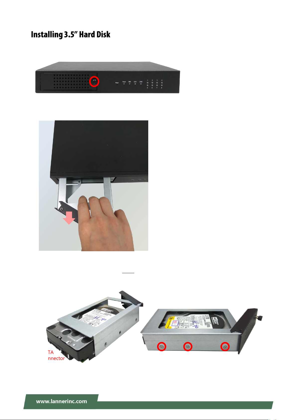
SATA
Connector
1. Loosen the screw that fixes the hard disk tray latch on the front panel.
2. Pull the tray out.
3. Secure the hard disk on the tray with three screws on each side. Make sure the SATA Connector faces
outward.
48
Page 49
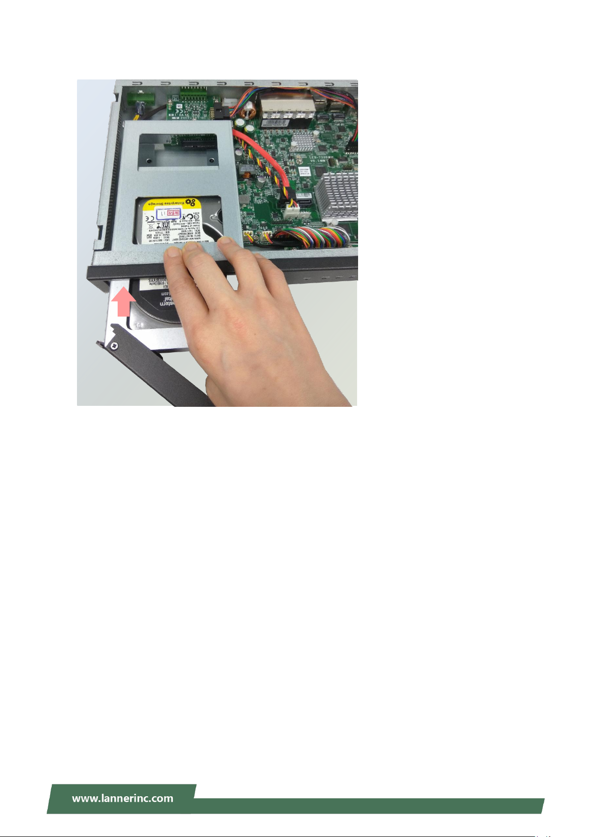
Chapter 4: Hardware Setup
4. Insert the tray into the bay and fasten the screw that fixes the hard disk tray on the front panel.
49
Page 50
NVA-3000 User Manual
Green
The system is powered and running
Orange
The system is restarting
Off
The system is powered off
Green
A hard disk is detected
Red
Hard disk error
Off
No hard disk is detected
Blinking Green
Operating as a Gigabit connection (1000 Mbps)
Orange
Operating as a 100-Mbps connection
Off
No link has been established
Blinking Green
The port is providing PoE power
Orange
Controlled by GPIO
Off
No power is being drawn from this port
PoE Power Status
LAN1 & LAN2
Link Activity
System
Power
HDD
Activity
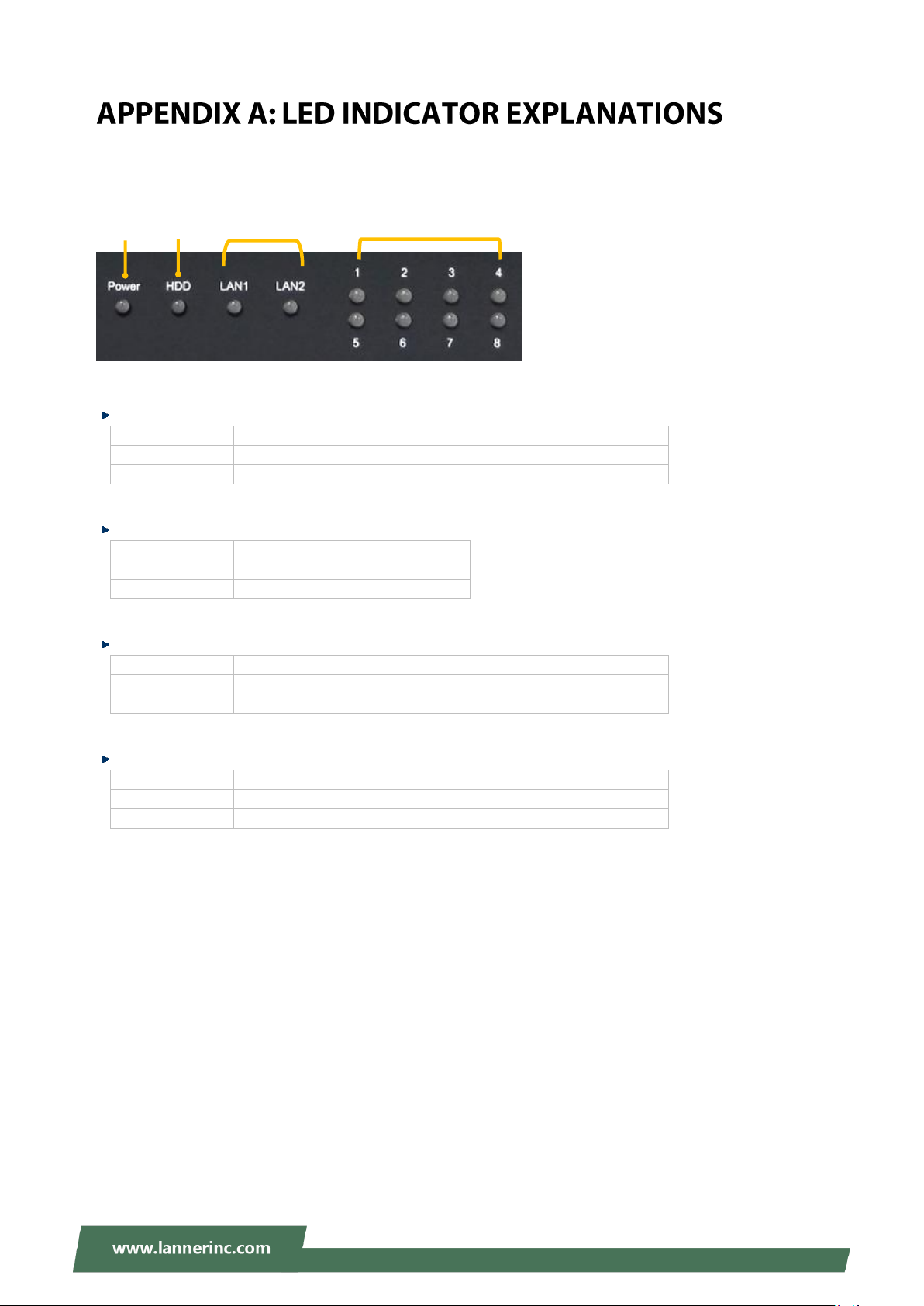
The status explanations of LED indicators on Front Panel are as follows:
System Power
HDD Activity
LAN1 & LAN2 Link Activity
PoE Power Status
50
Page 51
Appendix B: Setting up Console Redirections
Console redirection lets you monitor and configure a system from a remote terminal computer by
re-directing keyboard input and text output through the serial port. The following steps illustrate how to
use this feature. The BIOS of the system allows the redirection of the console I/O to a serial port. With this
configured, you can remotely access the entire boot sequence through a console port.
1. Connect one end of the console cable to console port of the system and the other end to the serial port
of the Remote Client System.
2. Configure the following settings in the BIOS Setup menu:
BIOS > Advanced > Serial Port Console Redirection > Console Redirection Settings, select 115200
for the Baud Rate, None. for Flow control, 8 for the Data Bit, None for Parity Check, and 1 for the Stop
Bit.
3. Configure console redirection related settings on the client system. You can use a terminal emulation
program that features communication with serial COM ports such as TeraTerm or Putty. Make sure the
serial connection properties of the client conform to those set in Step 2 for the server.
51
Page 52
NVA-3000 User Manual
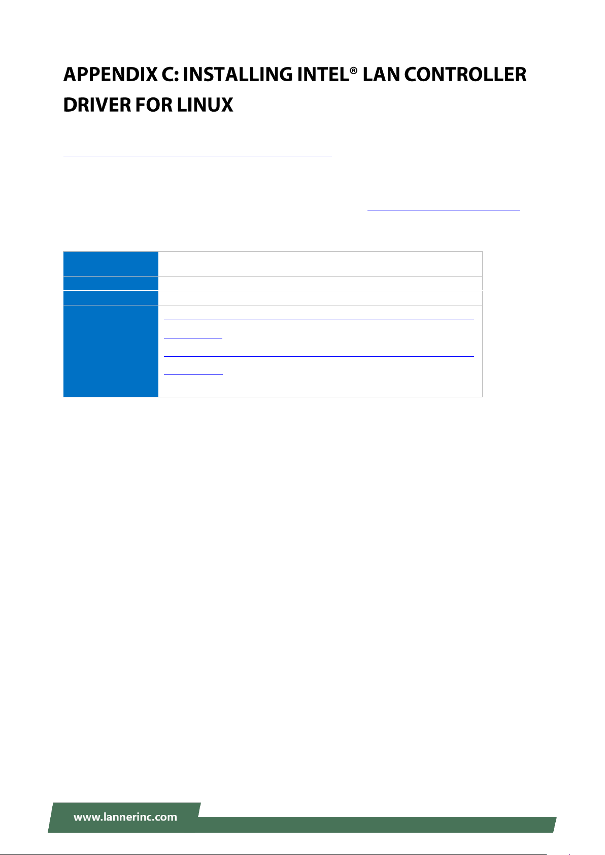
Product Name
Keyword
I210IT / I210IS
Download Type
Drivers
Operating System
Linux*
Product page
https://downloadcenter.intel.com/product/64402/Intel-Ethernet-Cont
roller-I210-IT
https://downloadcenter.intel.com/product/64401/Intel-Ethernet-Cont
roller-I210-IS
To install the Intel® LAN controller base driver for the Red Hat® and Linux operating system, please visit
http://www.lannerinc.com/support/download-center/drivers, enter the product category and download the
utility package.
For the latest driver update, please visit Intel® download center at https://downloadcenter.intel.com/, use
the keyword search or the filter to access the driver’s product page, and then download the latest controller
driver as well as the ReadMe document.
52
Page 53
Appendix D: Terms and Conditions
1. All products are under warranty against defects in materials and workmanship for a period of one year
from the date of purchase.
2. The buyer will bear the return freight charges for goods returned for repair within the warranty period;
whereas the manufacturer will bear the after service freight charges for goods returned to the user.
3. The buyer will pay for the repair (for replaced components plus service time) and transportation charges
(both ways) for items after the expiration of the warranty period.
4. If the RMA Service Request Form does not meet the stated requirement as listed on “RMA Service”, RMA
goods will be returned at customer’s expense.
5. The following conditions are excluded from this warranty:
Improper or inadequate maintenance by the customer
Unauthorized modification, misuse, or reversed engineering of the product
Operation outside of the environmental specifications for the product.
1. To obtain an RMA number, simply fill out and fax the “RMA Request Form“ to your supplier.
2. The customer is required to fill out the problem code as listed. If your problem is not among the codes
listed, please write the symptom description in the remarks box.
3. Ship the defective unit(s) on freight prepaid terms. Use the original packing materials when possible.
4. Mark the RMA# clearly on the box.
Note: Customer is responsible for shipping damage(s) resulting from inadequate/loose packing
of the defective unit(s). All RMA# are valid for 30 days only; RMA goods received after the
effective RMA# period will be rejected.
53
Page 54
NVA-3000 User Manual
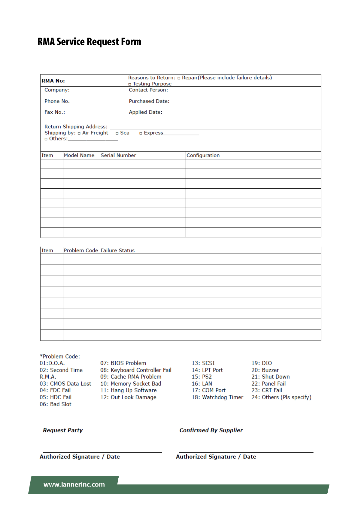
When requesting RMA service, please fill out the following form. Without this form enclosed, your RMA
cannot be processed.
54
 Loading...