

Page 1

Network Computing Platforms
NCA-4210
User Manual
Rev 1.2 September 26th, 2016
Page 2

Network Computing Platforms
Revision History
This document contains proprietary information of Lanner Electronics Inc. –and is not to be
disclosed or used except in accordance with applicable agreements.
Copyright © 2016. All Rights Reserved.
Copyright© 2016 Lanner Electronics Inc. All rights reserved. The information in this document
is proprietary and confidential to Lanner Electronics Inc. No part of this document may be
reproduced in any form or by any means or used to make any derivative work (such as
translation, transformation, or adaptation) without the express written consent of Lanner
Electronics Inc. Lanner Electronics Inc. reserves the right to revise this document and to make
changes in content from time to time without obligatio n on the part of La nner Electronics Inc. to
provide notification of such revision or chan ge.
The information in this document is furnished for informational use only, is subject to change
without notice, and should not be constr ued as a commitm ent by Lanner Electroni cs Inc. Lanner
Electronics Inc. assumes no responsibility or liability for any errors or inaccuracies that may
appear in this document or any software that may be provided in association with this document.
Rev Date Descriptions
0.1 2016/02/23 Preliminary
1.0 2016/02/26 Official release
1.1 2016/8/17 Modified memory specifications
1.2 2016/09/26 Modified cooling fan specifications
Page 3

Network Computing Platforms
Online Resources
The listed websites are links to the on-line product information and technical support.
Resource Website
Lanner www.lannerinc.com
Product
Resources
www.lannerinc.com/support/download-center
RMA http://eRMA.lannerinc.com
Acknowledgement
Intel, Pentium and Celeron are registered trademarks of Intel Corp.
Microsoft Windows and MS-DOS are registered trademarks of Microsoft Corp.
All other product names or trademarks are properties of their respective owners.
Compliances and Certification
CE Certification
This product has passed the CE test for environmental specifications. Test conditions for
passing included the equipment being operated within an industrial enclosure. In order to
protect the product from being damaged by ESD (Electrostatic Discharge) and EMI leakage,
we strongly recommend the use of CE-compliant industrial enclosure products.
FCC Class A Certification
This equipment has been tested and found to comply with the limits for a Class A digital device,
pursuant to Part 15 of the FCC Rules. These limits are designed to provide reasonable
protection against harmful interference when the equipment is operated in a commercial
environment. This equipment generates, uses and can radiate radio frequency energy and, if
not installed and used in accordance with the instruction manual, may cause harmful
interference to radio communications. Operation of this equipment in a residential area is likely
to cause harmful interference in which case the user will be required to correct the interference
at his own expense.
EMC Notice
This equipment has been tested and found to comply with the limits for a Class A digital device,
pursuant to Part 15 of the FCC Rules. These limits are designed to provide reasonable
protection against harmful interference when the equipment is operated in a commercial
environment. This equipment generates, uses, and can radiate radio frequency energy and, if
Page 4

Network Computing Platforms
not installed and used in accordance with the instruction manual, may cause harmful
interference to radio communications. Operation of this equipment in a residential area is likely
to cause harmful interference in which case users will be required to corre ct the interferen ce at
their own expense.
Safety Guidelines
z Follow these guidelines to ensure general safety:
z Keep the chassis area clear and dust-free before, duri ng and after installation.
z Do not wear loose clothing or jewelry that could get caught in the chassis. Fasten your tie
or scarf and roll up your sleeves.
z Wear safety glasses/goggles if you are working under any conditions that might be
hazardous to your eyes.
z Do not perform any action that creates a potential hazard to people or makes the
equipment unsafe.
z Disconnect all power by turning off the power and unplugging the power cord before
installing or removing a chassis or working near power supplies
z Do not work alone if potentially hazardous conditions exist.
z Never assume that power is disconnected from a circuit; always check the circuit.
LITHIUM BATTERY CAUTION:
Risk of explosion could occur if battery is replaced by an incorrect type. Please dispose of
used batteries according to the recycling instructions of your country.
z Installation only by a trained electrician or only by an electrically trained person who knows
all the applied or related installation and device specifications..
z Do not carry the handle of power supplies when moving to other place.
z The machine can only be used in a fixed location such as labs or computer facilities.
Operating Safety
z Electrical equipment generates heat. Ambient air temperature may not be adequate to
cool equipment to acceptable operating temperatures without adequate circulation. Be
sure that the room in which you choose to operate your system has adequate air
circulation.
z Ensure that the chassis cover is secu re. The chassis design allows cooling air to circulate
effectively. An open chassis permits air leaks, which may interrupt and redirect the flow of
cooling air from internal components.
Electrostatic discharge (ESD) can damage equipment and impair electrical circuitry. ESD
damage occurs when electronic components are improperly ha ndled and can result in
Page 5

Network Computing Platforms
complete or intermittent failures. Be sure to follow ESD-prevention procedures when removing
and replacing components to avoid these problems.
z Wear an ESD-preventive wrist strap, ensuring that it makes good skin contact. If no wrist
strap is available, ground yourself by touching the metal part of the chassis.
z Periodically check the resistance value of the antistatic strap, which should be between 1
and 10 megohms (Mohms).
Rackmounting Installation Environment Precaution
1. Elevated Operating Ambient - If installed in a closed or multi-unit rack assembly, the
operating ambient temperature of the rack environment may be greater than room ambient.
Therefore, consideration should be given to installing the equipment in an environment
compatible with the maximum ambient temperature (Tma) specified by the manufacturer.
2. Reduced Air Flow - Installation of the equipment in a rack should be such that the amount of
air flow required for safe operation of the equipment is not compromised.
3. Mechanical Loading - Mounting of the equipment in the rack should be such that a
hazardous condition is not achieved due to uneven mechanical loading.
4. Circuit Overloading - Consideration should be given to the connection of the equipment to
the supply circuit and the effect that overloading of the circuits might have on over-current
protection and supply wiring. Appropriate consideration of equipment nameplate ratings
should be used when addressing this concern.
5. Reliable Earthing - Reliable earthing of rack-mounted equipment should be maintained.
Particular attention should be given to supply connections other than direct connections to the
branch circuit (e.g. use of power strips).”
Consignes de sécurité
Suivez ces consignes pour assurer la securite generale :
z Laissez la zone du chassis propre et sans poussiere pendant et apres l’installation.
z Ne portez pas de vetements amples ou de bijoux qui pourraient etre pris dans le chassis.
Attachez votre cravate ou echarpe et remontez vos manches.
z Portez des lunettes de securite pour proteger vosmyeux.
z N’effectuez aucune action qui pourrait creer un dangermpour d’autres ou rendre
l’equipement dangereux.
z Coupez completement l’alimentation en eteignant l’alimentation et en debranchant le
cordon d’alimentation avant d’installer ou de retirer un chassis ou de travailler a proximite
de sources d’alimentation.
z Ne travaillez pas seul si des conditions dangereuses sont presentes.
Page 6

Network Computing Platforms
z Ne considerez jamais que l’alimentation est coupee d’un circuit, verifiez toujours le circuit.
Cet appareil genere, utilise et emet une energie radiofrequence et, s’il n’est pas installe et
utilise conformement aux instructions des fournisseurs de composants sans fil, il risque de
provoquer des interferences dans les communications radio.
Avertissement concernant la pile au lithium
z Risque d’explosion si la pile est remplacee par une autre d’un mauvais type.
z Jetez les piles usagees conformement aux instructions.
z L’installation doit etre effectuee par un electricien forme ou une personne formee a
l’electricite connaissant toutes les specifications d’installation et d’appareil du produit.
z Ne transportez pas l’unite en la tenant par le cable d’alimentation lorsque vous deplacez
l’appareil.
z La machine ne peut etre utilisee qu’a un lieu fixe comme en laboratoire, salle d’ordinateurs
ou salle de classe.
Sécurité de fonctionnement
z L’equipement electrique genere de la chaleur. La temperature ambiante peut ne pas etre
adequate pour refroidir l’equipement a une temperature de fonctionnement acceptable
sans circulation adaptee. Verifiez que votre site propose une circulation d’air adequate.
z Verifiez que le couvercle du chassis est bien fixe. La conception du chassis permet a l’air
de refroidissement de bien circuler. Un chassis ouvert laisse l’air s’echapper, ce qui peut
interrompre et rediriger le flux d’air frais destine aux composants internes.
z Les decharges electrostatiques (ESD) peuvent endommager l’equipement et gener les
circuits electriques. Des degats d’ESD surviennent lorsque des composants electroniques
sont mal manipules et peuvent causer des pannes totales ou intermittentes. Suivez les
procedures de prevention d’ESD lors du retrait et du remplacement de composants.
- Portez un bracelet anti-ESD et veillez a ce qu’il soit bien au contact de la peau. Si aucun
bracelet n’est disponible, reliez votre corps a la terre en touchant la partie metallique du
chassis. Verifiez regulierement la valeur de resistance du bracelet antistatique, qui doit etre
comprise entre 1 et 10 megohms (Mohms).
Consignes de sécurité électrique
z Avant d’allumer l’appareil, reliez le cable de mise a la terre de l’equipement a la terre.
z Une bonne mise a la terre (connexion a la terre) est tres importante pour proteger l
equipement contre les effets nefastes du bruit externe et reduire les risq ues d’electrocution
en cas de foudre.
z Pour desinstaller l’equipement, debranchez le cable de mise a la terre apres avoir eteint
l’appareil.
Page 7
Network Computing Platforms
z Un cable de mise a la terre est requis et la zone reliant les sections du conducteur doit
faire plus de 4 mm2 ou 10 AWG.
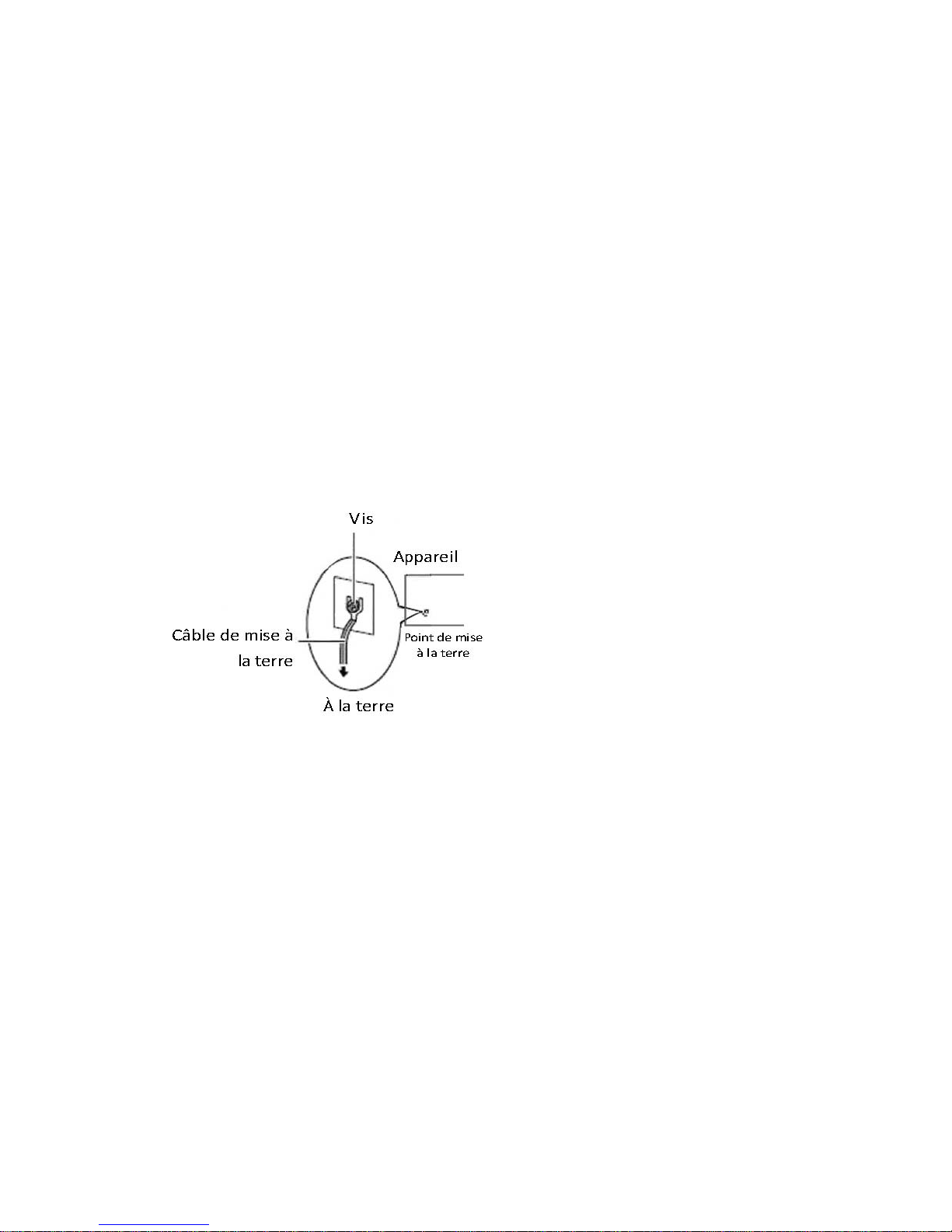
Procédure de mise à la terre pour source
d’alimentation CC Procédure de mise à la terre pour
source d’alimentation CC
• Desserrez la vis du termi nal de mise a la terre.
• Branchez le cable de mise a la terre a la terre.
• L’appareil de protection pour la source d’alimentation
CC doit fournir 30 A de courant. Cet appareil de protection doit etre branche a la source
d’alimentation avant l’alimentation CC.
Page 8

Network Computing Platforms
Table of Contents
Revision History ............................................................................................................2
Chapter 1: Introduction................................................................................................10
System Specification............................................................................................10
Ordering Information...........................................................................................12
Package Contents.................................................................................................12
Optional Accessories............................................................................................12
Chapter 2: System Overview.......................................................................................14
Mechanical Drawing – NCA-4210A...................................................................14
Mechanical Drawing – NCA-4210B ...................................................................15
Block Diagram.....................................................................................................16
Front I/Os.............................................................................................................17
Rear I/Os..............................................................................................................18
Chapter 3: Board Layout..............................................................................................19
Jumpers and Connectors on the Motherboard .....................................................19
Jumper Setting and Connector Pin-out................................................................21
Jumper Settings............................................................................................21
Connector Pin Assignments.........................................................................23
Chapter 4: Hardware Setup..........................................................................................28
Installing the CPU................................................................................................29
Installing the CPU Heat-Sink and Fan Duct........................................................32
Installing the System Memory.............................................................................35
Installing Disk Drives..........................................................................................36
Installing a mSATA Module.................................................................................38
Installing an IPMI Card .......................................................................................39
Replacing Cooling Fans.......................................................................................40
Installing Ethernet NIC Module...........................................................................41
Chapter 5: BIOS Setup.................................................................................................43
Main.......................................................................................................................44
Advanced ................................................................................................................45
Super IO Configuration................................................................................45
HW Monitor.................................................................................................49
Smart Fan Configuration..............................................................................50
Serial Port Console Redirection...................................................................51
COM Console Redirection Settings.............................................................52
CPU Configuration ......................................................................................57
SATA Configuration....................................................................................59
USB Configuration ......................................................................................62
Page 9

Network Computing Platforms
LAN Boot Select..........................................................................................64
Chipset .................................................................................................................65
System Agent (SA) Configuration:..............................................................65
Memory Configuration................................................................................66
PCH-IO Configuration.................................................................................67
Security ..................................................................................................................69
Boot.......................................................................................................................70
Save & Exit ..............................................................................................................75
Appendix A: Programming W atchdog Timer ..............................................................78
Appendix B: Setting up Console Redirection..............................................................79
Appendix C: Programming Generation 3 LAN Bypass ..............................................80
Appendix D: Programming the LCM..........................................................................82
Appendix E: Terms and Conditions.............................................................................87
Page 10

Network Computing Platforms
Chapter 1: Introduction
Thank you for choosing NCA-4210. The internal core of NCA-4210 is the 6th generation
Intel® 14nm microprocessor, the new LGA 1151 socket, DDR4 memory support and the I/O
boosting, comprehensive Intel® H110 and C236 series chipset, and flexible LAN
configurations. The adoption of the 6th generation Intel® Core™ processor comes with the
promise to enhance processor performance, while lowering the TDP. NCA-4210 supports
flexible LAN configurations. Depending on the SKUs, there are Ethernet connectivity options of
6 x RJ-45 GbE LAN + 2 x SFP GbE LAN with 2 pairs of bypass, and 6 x RJ-45 GbE LAN with 2
pairs of bypass.
Here is the summary of the key features:
z 6
th
generation Intel® Core™ processor codenamed Skylake
z PCH: Intel® H110 or C236
z 2 x DDR4 2400MHz ECC/UDIMMs (Up to 16GB each)
z 1 x 3.5” or 2 x 2.5” SATA HDD/SSD drive bays (disk drive is not included)
z 1 x mSATA socket
z 1 x OPMA socket for IPMI
Please refer to the following chart for a detailed description of the system's specifications.
System Specification
Processor Options
Intel® Core™ i7-6700, i5-6500 or Xeon
E3-1200 v5 Series processor (codenamed
Skylake)
PCH
Intel H110 or C236
Socket
LGA1151
CPU TDP
Approximately 65W
Super I/O
NCT6776
BIOS
AMI SPI BIOS
z Support PXE function
z Support Console redirection
z Watchdog/ Watchdog control LAN Bypass
function/ Power off LAN Bypass function
System Memory
2 x DDR4 2400MHz ECC/UDIMMs (Up to
16GB each)
Page 11

Network Computing Platforms
USB
2 x USB 3.0 Type-A ports
Storage
1 x 3.5” or 2 x 2.5” HDD/SSD (the drive is not
included)
1 x mSATA socket via mini-PCIe interface
LAN Model-A: 6 x RJ-45 GbE Ethernet ports
Model-B: 6 x RJ-45 GbE Ethernet ports and 2 x
SFP ports
Controller
Model-A: 6 x Intel i210-AT
Model-B: 6 x Intel i210-AT + 2 x Intel i210-IS
Management N/A
NIC Module
space
1 x Slim Type NIC module socket (PCIe Gen3 x
8 interface) supporting
1/10/40G/Fiber/Copper/Bypass
Console 1 x RJ-45 console port
IPMI OPMA socket to support IPMI
Networking
Bypass 2 pairs of LAN bypass on RJ-45 ports
Fan
2 x Cooling fans
LCM 1x characte r type LCM
LED POWER/STATUS/HDD
Display
Keypad 4x Keypads
Expansion
Optional PCIe riser card for rear expansion
TPM
Optional
Thermal
CPU heatsink with fan duct
Form Factor 1U rackmount
Housing SPGC
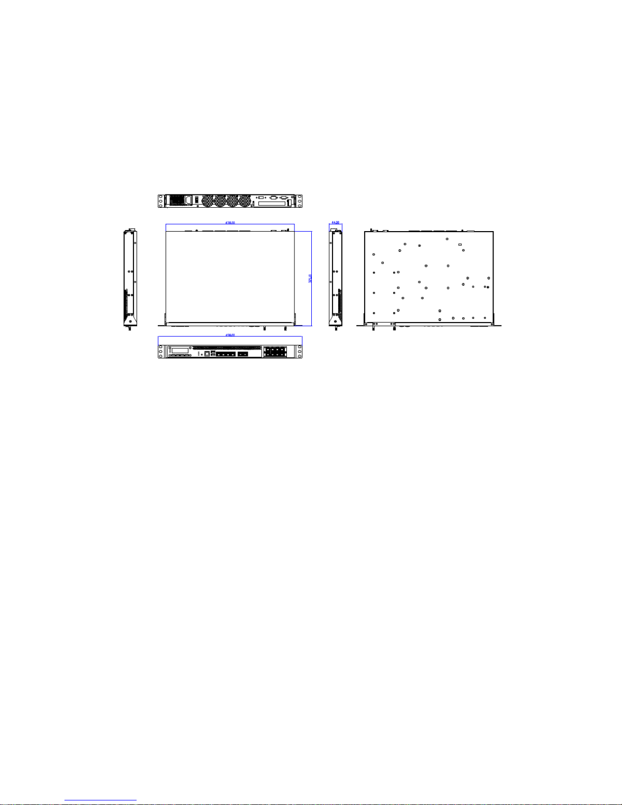
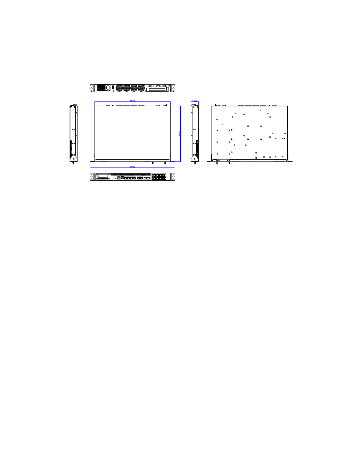
Dimensions 438mm x 320mm x 44mm (W x D x H)
Physical
Characteristics
Mounting
Options
Rackmount by sliderail
Operating
Temperature
0℃~40°C
Non-operating
Temperature
-40℃~70℃
Environment
Ambient
Humidity
5 to 90% (non-condensing)
Input AC 90 to 264V@47 to 63Hz
Power
Power supply 220W single PSU
Page 12

Network Computing Platforms
EMC CE/FCC Class A/UL
Green product RoHS
Certifications
Ordering Information
NCA-4210A
1U x86 Rackmount Network Appliance based on the 6th Generation
Intel Core Processor (codename Skylake-S) with Intel H110 PCH, 6
GbE RJ45 with 2 pairs bypass and 1 NIC Module Slot
NCA-4210B
1U x86 Rackmount Network Appliance based on the 6th Generation
Intel Xeon/Core Processor (codename Skylake-S) with Intel C236
PCH, 6 GbE RJ45 with 2 pairs bypass, 2 SFP GbE ports and 1 NIC
Module Slot
Package Contents
Please unpack your package carefully and inspect all the following items
1 – NCA-4210 Network Security Platform
1 – power cable
1 – Short Ear Rack mount kit with screws
1 – Console cable
1 – LAN Cable (Grey)
Optional : 1U slide rail kit
Note:If you should find any components missing or damaged, please contact your dealer
immediately for assistance
Optional Accessories
NCS2-IGM428A
1x Intel i350 4port RJ45 w/ 2pairs bypass
NCS2-IGM806A
2x Intel i350 8port RJ45 w/ 4pairs bypass
NCS2-ISM405A
1x Intel i350 4port SFP w/ bypass
NCS2-ISM406A
1x Intel i350 4port SFP w/o bypass
NCS2-ISM802A
2x Intel i350 8port RJ45 w/o bypass
NCS2-IXM205A
1x Intel 82599 2port SFP+ w/ bypass
NCS2-IXM405A
2x Intel 82599 4port SFP+ w/o bypass
NCS2-IGM427
NCS2-MTX401
Page 13

Network Computing Platforms
NCS2-IQM201A
NCS2-IXM407A
AV-ICE01
AV-ICE02
AV-ICE03
AV-ICE04
AV-CVE20000
Page 14
Network Computing Platforms
Chapter 2: System Overview
Mechanical Drawing – NCA-4210A
Unit: mm
Page 15
Network Computing Platforms
Mechanical Drawing – NCA-4210B
Unit: mm
Page 16
Network Computing Platforms
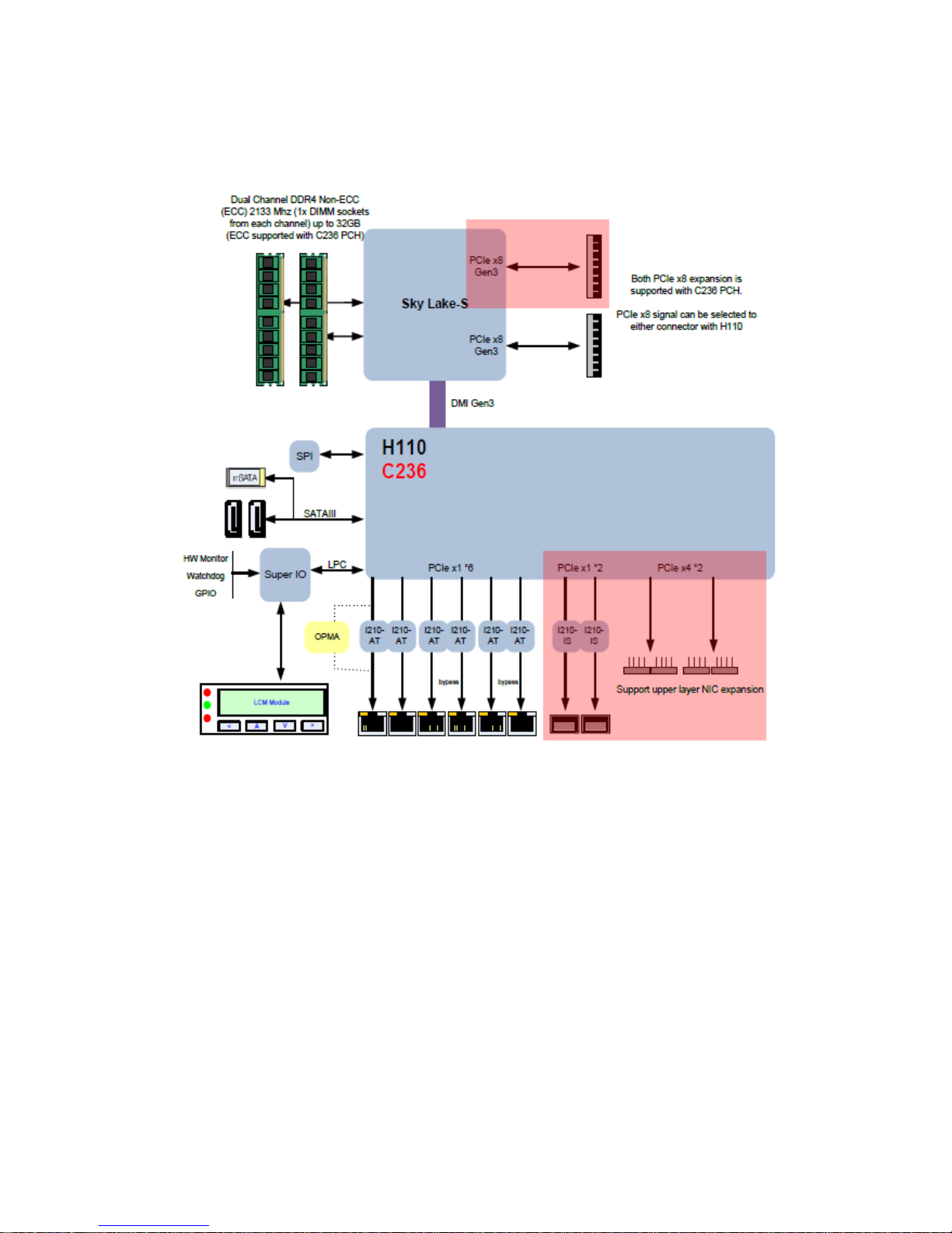
Block Diagram
Note:
The 2 x 10G SFP+ ports are only available in model B.
Page 17
Network Computing Platforms
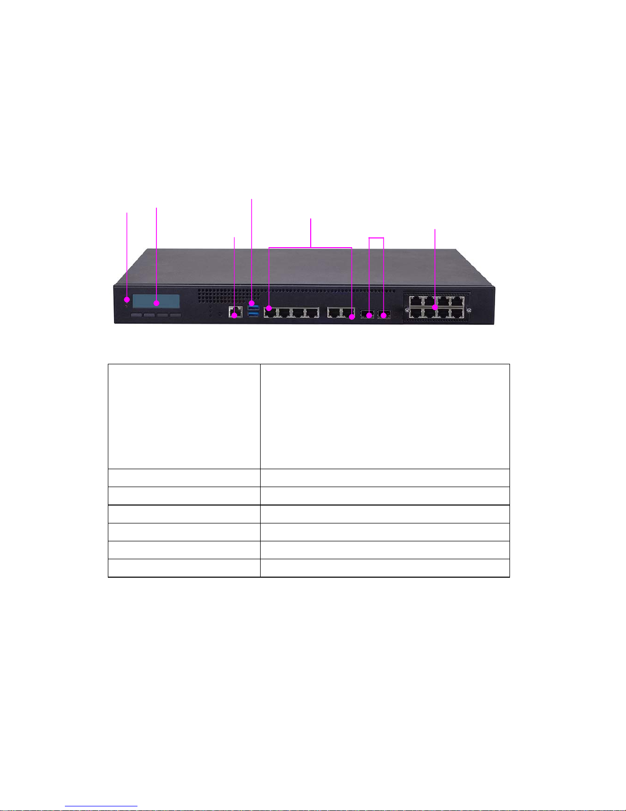
Front I/Os
F1 LED Indicators
POWER/STATUS/HDD
Power: status about power supply
Status: programmable status LED signals for
system activities
HDD: status about storage devices, such as HDD
or SSD
F2 LCM LCM with 4 x keypads
F3 Console
1 x RJ-45 console port
F4 USB
2 x USB 3.0 Type-A ports in double stacked form
F5 LAN
6 x RJ-45 GbE ports
F6 SFP LAN
2 x SFP LAN ports (available in model-B only)
F7 NIC
1 x NIC module space with PCIe interface
F1
F2
F3
F4
F5
F6
F7
Page 18
Network Computing Platforms
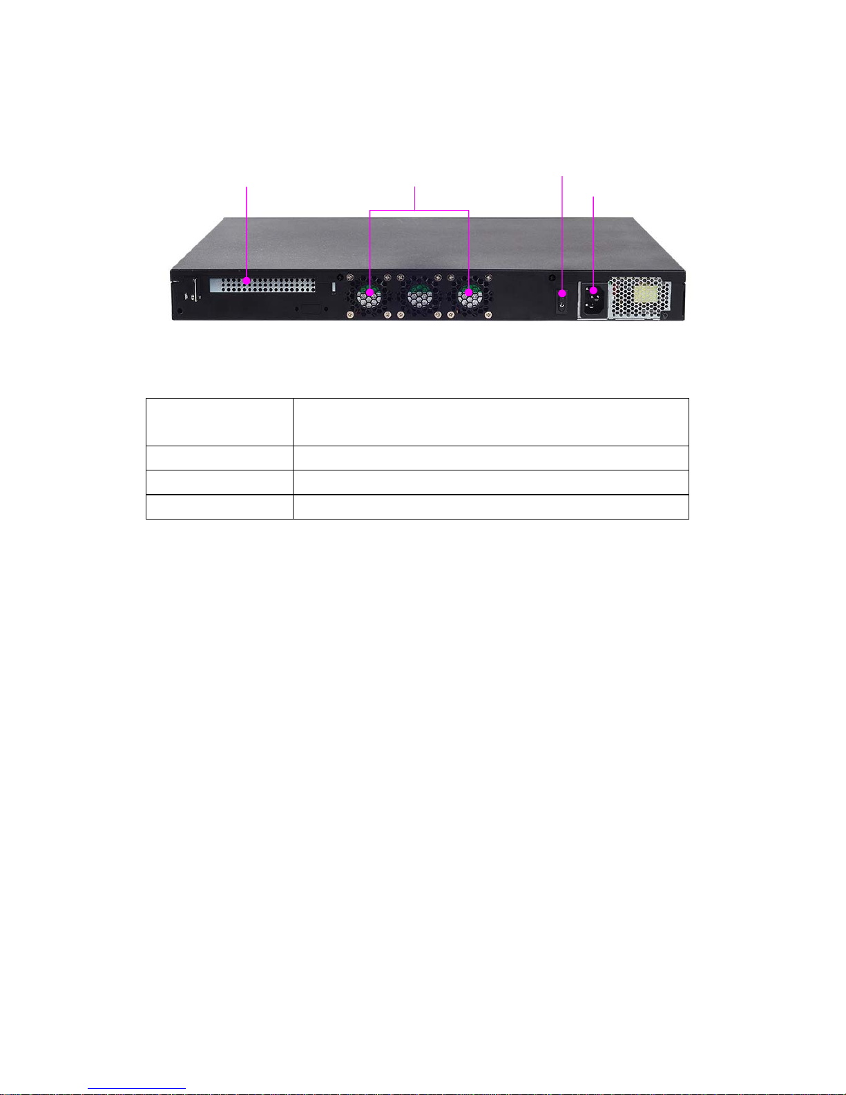
Rear I/Os
R1 PCIe
Expansion
1 x PCIe expansion slot (optional)
R2 Fans 3 x cooling fans
R3 Power switch 1 x power on/off switch
R4 power jack 1 x power jack for connection with power adapter
R1
R2
R3
R4
Page 19
Network Computing Platforms
Chapter 3: Board Layout
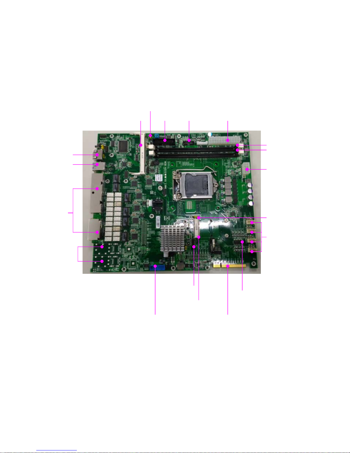
Jumpers and Connectors on the Motherboard
Notes: SFP ports are in model-B only.
FAN1-4
ATX1
DIO1
PCIESLOT1 JUSB1
mSATA
SPIROM1
J1
DIMM1/2
ATX2 VGA1 LCM1
J5
OPMA1
COM1
USB1
LAN
SFP
Page 20
Network Computing Platforms
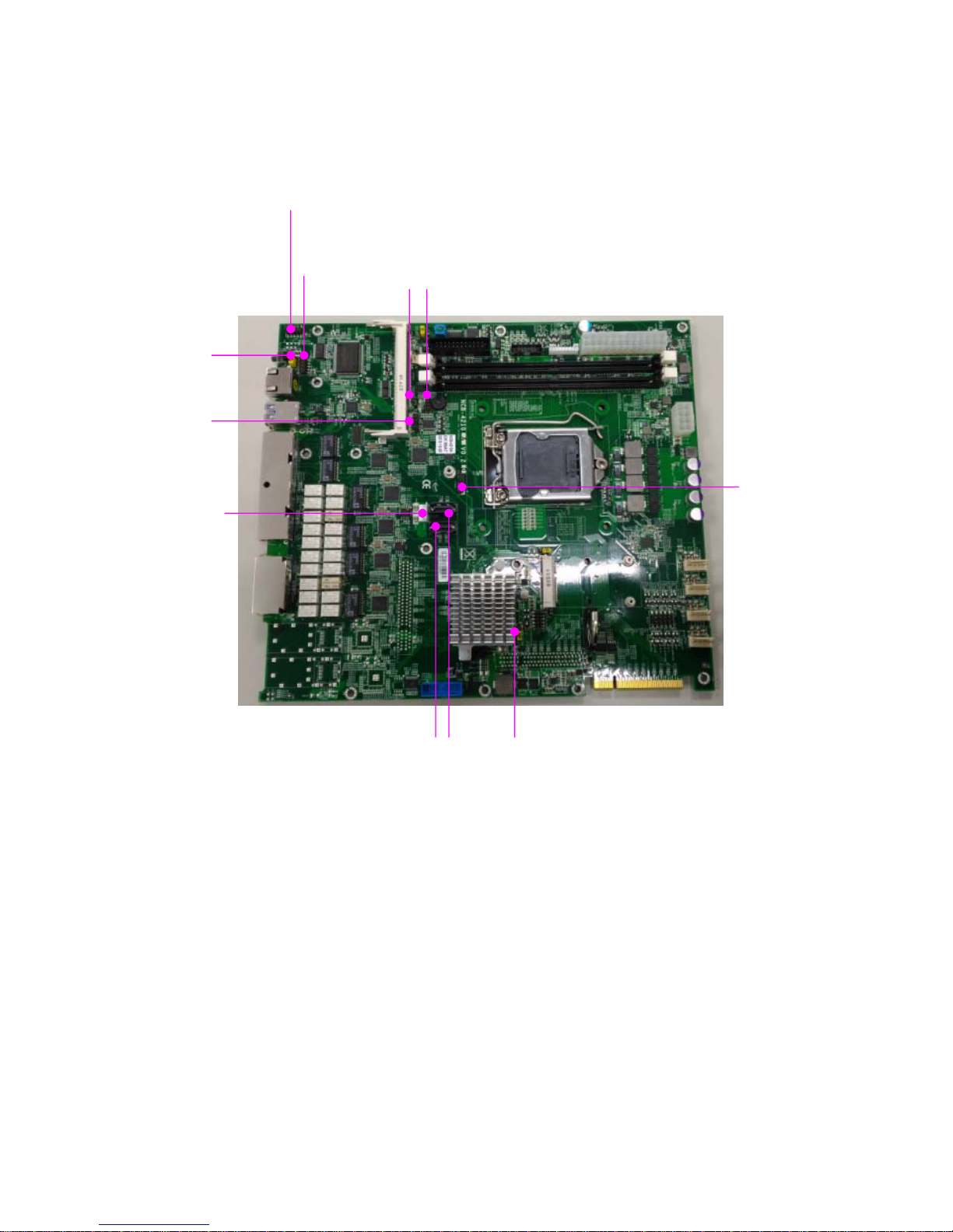
Jumpers and Connectors on the Motherboard (cont’d)
Notes: TPM is optional.
J4 SATA2/3
CON1
JTPM1
J9 J7
80PORT1
J6
J8
J18
Page 21
Network Computing Platforms
Jumper Setting and Connector Pin-out
Jumper Settings
J4:RTC reset - the clear CMOS jumper
J6:RESET - the jumper to set hardware or software reset
J1:PCIE Reversal Function - the jumper to set PCIe normal or reversal behavior
J2:PCIE X8 X4 Function – select PCIe x4 or x8 mode
Short Pins Description
1-2 (Default) Normal
2-3 Clear CMOS
Short Pins Description
1-2 Hardware Reset
2-3(Default) Software Reset
Short Pins Description
1-2(Default) PCIE Normal
2-3 PCIE Reversal
1
2
3
1
2
3
1
2
3
1
2
3
Page 22
Network Computing Platforms
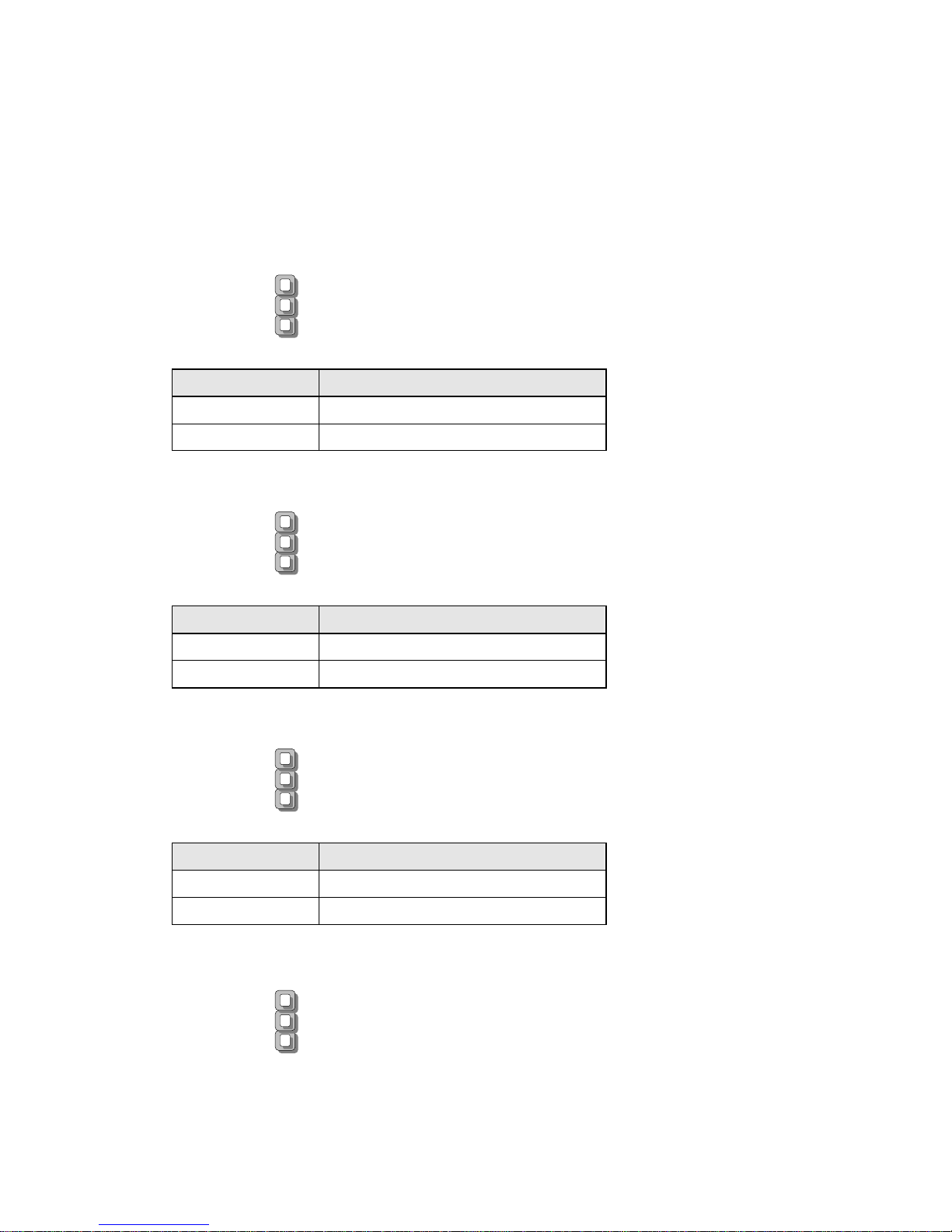
J3:PCIE X8 X4 Function – select PCIe x4 or x8 mode
Short Pins Description
1-2(Default) PCIE 2X8
2-3 PCIE 1X8 1X4 1X4
J5:POWER Button Function – select ATX or AT power mode
Short Pins Description
1-2(Default) ATX MODE
2-3 AT MODE
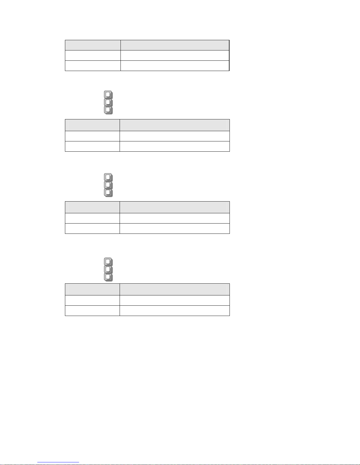
J9:GEN3 Bypass Flash Jumper – select “No Flash” or “Flash” mode
Short Pins Description
1-2(Default) No flash
2-3 flash
Short Pins Description
1-2 PCIE 1X8 1X4 1X4
2-3(Default) PCIE 2X8
1
2
3
1
2
3
1
2
3
Page 23

Network Computing Platforms
Connector Pin Assignments
USB3.0/2.0 Interfaces
JUSB1:USB Connector 2x10 Pins 2.0mm
USB1:USB3.0 double-stacked type-A connectors
PIN NO. DESCRIPTION PIN NO. DESCRIPTION
1 V5USB 11 D2+
2 USB3_RX1_N 12 D23 USB3_RX1_P 13 GND
4 GND 14 USB3_TX2+1
5 USB3_TX1_N 15 USB3_TX2-1
6 USB3_TX1_P 16 GND
7 GND 17 USB3_RX2+1
8 D1- 18 USB3_RX2-1
9 D1+ 19 VBUS
10 KEY 20 KEY
Serial Console Interface
COM1: serial console pin definitions
1
8
Page 24
Network Computing Platforms
Pin number Pin signal In/Out
1
Request To Send (RTS)
2 Data Terminal Ready (DTR)
3 Transmitted Data (TxD)
4 Signal Ground
5 Signal Ground
6 Received Data (RxD)
7 Data Set Ready (DSR)
8 Clear To Send (CTS)
J18: internal pin header for serial connection
Pin number Pin signal In/Out
1
Data Carrier Detect (DCD)
2 Data Set Ready (DSR)
3 Received Data (RxD)
4 Request To Send (RTS)
5 Transmitted Data (TxD)
6 Clear To Send (CTS)
7 Data Terminal Ready (DTR)
8 Ring Indicator (RI)
SATA Interface
SATA2/SATA3: 7-pin SATA signal connector for SATA storage devices
J15
7P
1
1
2
2
3
3
4
4
5
5
6
6
7
7
PAD1
PAD1
PAD2
PAD2
1
2
9
10
Page 25
Network Computing Platforms
Pin number Pin signal In/Out
1
Ground
2 TX+
3 TX-
4 Ground
5 RX-
6 RX+
7 Ground
FAN connectors
FAN1~FAN4 cooling fan pin definition
Pin
Description
1
GND
2
P12V
3
FANIN
4
NC
5
FANOUT
VGA Interface
VGA1: Internal VGA Connector
Pin No. Description Pin No. Description Pin No. Description
1 CRT-R 6 GND 11 DDC_DATA
2 GND 7 AHSYNC 12 DDC_CLK
3 CRT-G 8 NC
4 GND 9 AVSYNC
5 CRT-B 10 GND
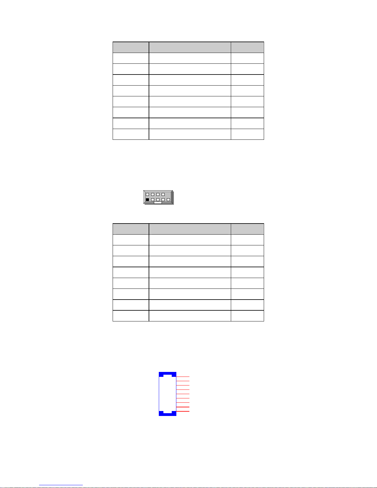
Digital I/O
DIO1: DIO connector
PIN DESCRIPTION PIN DESCRIPTION
1 GPO_1 2 GPI_1
3 GPO_2 4 GPI_2
5 GPO_3 6 GPI_3
7 GPO_4 8 GPI_4
9 GND 10 GND
Page 26
Network Computing Platforms
ATX powe r
ATX1: 8-pin ATX power supply connector
Part reference: ATX1
Pin Pin signal
1
Ground
2
VCC12 (12V)
3
Ground
4
VCC12 (12V)
5
Ground
6
VCC12 (12V)
7
Ground
8
VCC12 (12V)
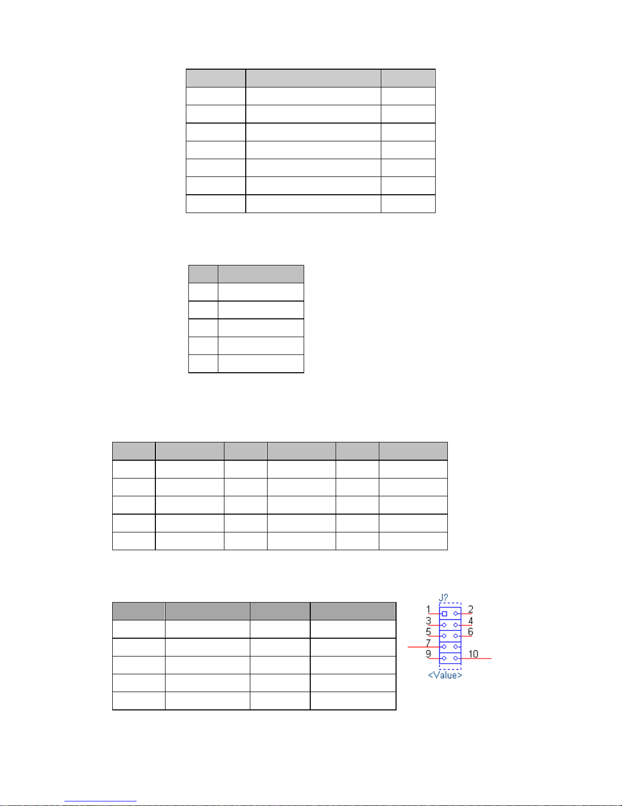
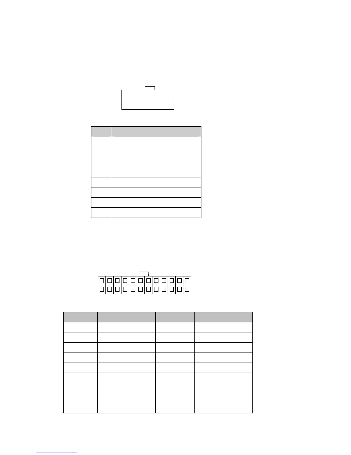
ATX2: 24-pin ATX power supply connector
Part reference: ATX2
Pin Description Pin Description
1 +3.3V 2 +3.3V
3 +3.3V 4 -12V
5 Ground 6 Ground
7 +5V 8 PSON9 Ground 10 Ground
11 +5V 12 Ground
13 Ground 14 Ground
15 Power Good 16 NC
17 Stand-By 5V 18 +5V
1
2
23
24
1
28
7
○ ○ ○ ○
○ ○ ○ ○
Page 27

Network Computing Platforms
19 +12V 20 +5V
21 +12V 22 +5V
23 +3.3V 24 Ground
Page 28

Network Computing Platforms
Chapter 4: Hardware Setup
Preparing the Hardware Installation
To access some components and perform certain service procedures, you must perform the
following procedures first.
WARNING:
z To reduce the risk of personal injury, electric shock, or damage to the equipment, please
remove all power sources.
z Please wear ESD protected gloves before conducting the following steps.
1. Power off NCA-4210 completely.
2. Remove the two screws at the rear, as circled in the figures below.
3. Slide and pull the top compartment as the arrow of direction below.
Page 29

Network Computing Platforms
4. Lift the top compartment.
Installing the CPU
The motherboard supports 1 x 6th Generation Intel CPU (codenamed Skylake) with LGA1151
socket. Please follow the steps below for installing the processor.
1. Press the load lever as shown in the figure below.
Page 30

Network Computing Platforms
2. Hold and drag the load lever outwards.
3. Drag the load lever out of the latch.
Page 31

Network Computing Platforms
4. Move the load lever as shown in the image below.
5. Once the cover is opened, you can install the CPU. Then, reverse the steps to securely lock
the CPU socket.
Page 32

Network Computing Platforms
Installing the CPU Heat-Sink and Fan Duct
The system is supplied with a CPU heat sink and a fan duct as its thermal solution. Please
refer to the steps below.
1. Prepare the supplied heat sink and place it on top of the CPU socket. Make sure the 4
screws on the heat sink align with the 4 screw-holes on the motherboard.
2. Tighten the four screws.
Page 33

Network Computing Platforms
3. Prepare the supplied fan duct. The fan duct will serve as the heat radiation bracket for the
CPU and the motherboard.
4. Fold the fan duct as shown in the image below.
5. Place the folded fan duct on top of the heat sink. Please make sure the screw-holes are
aligned. Then apply two screws.
Page 34

Network Computing Platforms
6. Remove the double-sided tapes on the back, as pointed by the two arrows in the diagram
below.
7. Fold and attach the tape of the right side of the fan duct to the aluminum bracket as shown
in the image below.
Page 35

Network Computing Platforms
8. Insert the part with tape at the corner between the two cooling fans. Then attach the tape to
the fan as shown in the image below.
Installing the System Memory
The motherboard supports DDR4 ECC/UDIMM up to 2,400MHz memory at max. 16GB per
socket. Please follow the steps below to install the DIMM memory modules.
1. Power off the system and locate the DDR DIMM slot.
2. Pull open the DIMM slot latches
3. Align the DIMM module and make sure the notches of the module aligned with the socket
keys in the slot.
4. Insert the module into the slot until it’s firmly seated and close the latches.
Page 36

Network Computing Platforms
Installing Disk Drives
The system supports 1 x 3.5” or 2 x 2.5” SATA HDDs or SSDs as data storage. Please follow
the steps below for installation. (Note: the following steps are based on 2 x 2.5” SATA disk
drives installation).
1. Locate the disk drive tray at the corner of the system.
2. Slide the tray downwards. Then the tray will be loosened from the two latching spots.
Page 37

Network Computing Platforms
3. Take the tray out and prepare to install a SATA 2.5” disk drive.
4. Place the disk drive as shown in the image below. Apply 2 screws for each side of the disk
drive.
5. Place the tray with HDD/SSD installed back to its original spot inside the system.
Remember to aim the two latching holes. Then slide the tray upwards to get it locked by the
two latching spots.
SATA connector this way
Page 38

Network Computing Platforms
6. Establish SATA cable connection between the disk drive and the motherboard. Please
apply 15+7 SATA cable to the drive while using SATA 7-pin connector and SATA 4-pin
connector for the motherboard.
Installing a mSATA Module
The motherboard provides one mSATA slot. Follow the procedures below for installing a
mSATA card.
1. Locate the mSATA socket.
2. Insert a mSATA module as shown in the image below card.
3. Press the module down and apply two screws to secure it.
Page 39

Network Computing Platforms
Installing an IPMI Card
The motherboard provides one OPMA socket which is used to install an IPMI card. Please
follow the steps below for instructions.
1. Locate the OPMA socket.
2. Insert an IPMI card into the socket and then press it down.
3. Apply a screw to secure the IPMI card.
Page 40

Network Computing Platforms
Replacing Cooling Fans
NCA-4210 supports 2 cooling fans. To replace a worn-down fan, please follow the steps
below.
1. Remove the screws circled below.
2. Apply some force and pull the fan out of its original place, as shown in the image below.
3. Unplug the fan connector.
4. To install a new one, just place the new fan to the original place and apply two screws.
Page 41

Network Computing Platforms
Installing Ethernet NIC Module
NCA-4210 supports one Ethernet NIC module space to expand it s network th roughput. Plea se
follow the instructions below.
Notes: For information about compatible modules, please refer to the “Ordering Information”
and “Optional Accessories” sections, or contact Lanner for more details.
1. Rotate and loosen the two captive screws on the bezel of the module slot and then remove
the bezel.
2. Position the gold finger of module as shown in the image below. When sliding the module
into the slot, make sure the module stays in the guides of the expansion slot.
Page 42

Network Computing Platforms
3. Slide your Ethernet NIC module into the space, until it is firmly attached.
4. Secure the module with two captive screws on the bezel.
Page 43

Network Computing Platforms
Chapter 5: BIOS Setup
To enter the BIOS setup utility, simply follow the steps below:
1. Boot up the system.
2. Press <Delete> during the boot-up. Your system should be running POST
(Power-On-Self-Test) upon booting up.
3. Then you will be directed to the BIOS main screen.
4. Instructions of BIOS navigations:
[<--] [-->]: select a setup screen, for instance, [Main], [Advanced], [Chipset], [Boot], [Security],
and [Save & Exit]
[↑] [↓]: select an item/option on a setup screen
Enter: select an item/option or enter a sub-menu
ESC: exit the current screen
+/- = to adjust values for the selected setup item/option
F1 = to display General Help screen
F2 = to retrieve previous values, such as the parameters configured the last time you had
entered BIOS.
F3 = to load optimized default values
F4 = to save configurations and exit BIOS
Notes: the images in the following section are for reference only.
Page 44

Network Computing Platforms
Main
The [Main] is the first setup screen when you enter BIOS. The [Main] displays general system
and BIOS information and you may configure “System Date”, and “System Time”.
BIOS Information
BIOS Vendor: displays BIOS vendor information
BIOS Version: displays BIOS version
Build Date and Time: displays the date and time the BIOS was built.
Press “Enter” if you want to configure “System Language”, “System Date”, and “System
Time”.
System Date: Day/Month/Year
System time: Hour/Minutes/Seconds
Page 45

Network Computing Platforms
Advanced
Use [<--] / [-->] to select [Advanced] setup screen. Under this screen, you may use [↑] [↓] to
select an item you wish to configure.
Super IO Configuration
Press “Enter” to access configuration sub-menu for super IO chip parameters. You may
access settings for Serial Port 1 or 2 or the Parallel port.
Page 46

Network Computing Platforms
Once you have entered Super I/O configuration, you may choose to configure Serial Port 1 or
2, or the Parallel port.
Super IO Configuration - Serial Port 1 Configuration
Press “Enter” to enable or disable the Serial Port 1 (COM). Device setting is fixed as default.
Page 47

Network Computing Platforms
Super IO Configuration - Serial Port 2 Configuration
Once Serial Port 2 is accessed, you may press “Enter” to enable or disable the Serial Port 2
(COM). Device setting is fixed as default.
Page 48

Network Computing Platforms
Parallel Port Configuration
This option allows you to set parameters for parallel port (LPT/LPTE).
Once Parallel Port is accessed, you may press “Enter” to enable or disable the Parallel Port.
Device setting is fixed as default.
Page 49

Network Computing Platforms
HW Monitor
This option allows you to view hardware health status.
Page 50

Network Computing Platforms
Smart Fan Configuration
This option allows you to configure parameters about the cooling fans. Press “Enter” to
access the submenu.
CPU Smart Fan Mode
Once Serial Port 2 is accessed, you may press “Enter” to enable or disable “Smart Fan
Mode”.
Page 51

Network Computing Platforms
Serial Port Console Redirection
This option allows you to configure parameters about serial port console redirection. Press
“Enter” to access the submenu.
Console Redirection: select “Enabled” or “Disable” for COM port console redirection.
The default is “Enabled”.
Page 52

Network Computing Platforms
Console Redirection Settings: select this item to enter the setting sub-menu.
COM Console Redirection Settings
Terminal Type: the emulation configuration. Select “VT100”, “VT100+”, “VT-UTF8” or
“ANSI”.
VT100: ASCII character set
VT100+: extends VT100 to support color function keys
VT-UTF8: uses UTF8 encoding to map Unicode characters onto 1 or more
ANSI: Extended ASCII character set
Page 53

Network Computing Platforms
Bits per second: select “9600”, “19200”, “38400”, “57600”, or “115200” for bits per
second. The Bps will determine serial port transmission speed. The speed must be matched
on the other side. Long or noisy lines may require lower speeds
Data Bits: select the value for data bits. In this case, “7” or “8”.
Page 54

Network Computing Platforms
Parity Bits: a parity bit can be sent with the data bits to detect some transmission errors.
Select “None”, “Even”, “Odd”, “Mark” or “Space”.
Stop Bits: stop bits indicate the end of a serial data packet. The standard is 1 stop bit.
Communication with slow devices may require more than 1.
Page 55

Network Computing Platforms
Flow Control: flow control can prevent data loss from buffer overflow. When sending data, if
the receiving buffers are full, a “stop” signal can be sent to stop the data flow. You may select
“None” or “Hardware RTS/CTS”, depending on the circumstances.
VT-UTF8 Combo Key Support: this option enables/disables VT-UTF8 combination key
support for ANSI/VT100 terminals.
Page 56

Network Computing Platforms
Recorder Mode: on this mode, when “Enabled”, only text will be sent. This is to capture
terminal data.
Putty KeyPad: select Function Key and Key Pad on Putty. You may select “VT100”,
“LINUX”, “XTERMR6”, “SCO”, “ESCN”, or “VT400”.
Page 57

Network Computing Platforms
CPU Configuration
This option allows you to configure CPU parameters.
Active Processor Cores: number of cores to enable in each processor package. The
default is “All” for optimization.
Page 58

Network Computing Platforms
You may press ‘‘Enter’’ to select the number of cores to be enabled.
Execute Disable Bit: an Intel hardware-based protection against malicious code. It will
detect the memory in which a code can be executed or not. When enabled, it will prevent
certain classes of malicious buffer overflow attacks when combined with a supporting OS.
When disabled, it forces the XD feature flag to always return 0.
Page 59

Network Computing Platforms
SATA Configuration
Press Enter to access items for SATA devices and settings.
SATA Mode Selection:
the selection to determine how SATA controllers operate.
Page 60

Network Computing Platforms
You may select ‘‘AHCI’’ or ‘‘ RAID’’ mode. Please be noted that there must be two SATA disk
drives installed in order to enable RAID mode.
mSATA:
enable or disable the mSATA port
Page 61

Network Computing Platforms
SATA1: enable or disable the SATA1 port
SATA2: enable or disable the SATA2 port
Page 62

Network Computing Platforms
USB Configuration
This option allows you to configure USB device Settings.
USB Devices:
displays USB devices
Legacy USB Support: this function enables or disables legacy USB support. Auto option
disables legacy support if no USB devices are connected. Disable option will keep USB
devices available only for EFI applications.
Page 63

Network Computing Platforms
You may select ‘‘Enabled’’, ‘‘ Disabled’’ or ‘‘Auto’’ .
Page 64

Network Computing Platforms
LAN Boot Select
This option allows you to select one of the onboard LAN boot. Press “Enter” to access the
sub-menu.
On Board LAN Boot:
the default is “Disabled”
Page 65

Network Computing Platforms
Chipset
Use [<--] / [-->] to select [Chipset] setup screen. Under this screen, you may use [↑] [↓] to
select ‘‘System Agent (SA) Configuration’’ or ‘‘PCH-IO Configuration’’.
System Agent (SA) Configuration: displays and provides options to configure system
agent (SA) parameters
VT-d: select “Enabled” or “Disabled” for Intel VT-d virtualization function.
Page 66

Network Computing Platforms
Memory Configuration
Memory Configuration provides memory configuration parameters.
Once accessed, information about memory frequency, total memory, and DIMM#1/2 status will
be displayed.
Page 67

Network Computing Platforms
PCH-IO Configuration
PCH-IO configuration provides PCH parameters.
Intel PCH RC Version: displays Intel PCH RC version
Intel PCH SKU Name: displays PCH SKU name
Intel PCH Rev ID: displays Intel PCH revision ID
Restore On Power Loss: select “Restore On Power Loss” options: Power On, Power Off, or
Last Status.
Page 68

Network Computing Platforms
Page 69

Network Computing Platforms
Security
Use [<--] / [-->] to select [Security] setup screen. Under this screen, you may use [↑] [↓] to
select an item you want to configure.
Administrator Password: set administrator password. Once set, then this only limits
access to Setup and is only asked for when entering Setup.
User Password: set user password. Once set, then this is a power-on password and must
be entered to boot or enter Setup.
Page 70

Network Computing Platforms
Boot
Use [<--] / [-->] to select [Boot] setup screen. Under this screen, you may use [↑] [↓] to select
an item you want to configure.
Boot mode select: select boot mode LEGACY or UEFI.
Page 71

Network Computing Platforms
Boot Option #1: determine the device to be the first system boot device.
Boot Option #2: determine the device to be the second system boot device.
Page 72

Network Computing Platforms
Boot Option #3: determine the device to be the third system boot device.
USB Device BBS Priorities:
specifies the boot device priority sequence from available
USB drives.
Page 73

Network Computing Platforms
Boot Option #1: set the device to be the first system boot device.
Boot Option #2: determine the device to be the second system boot device.
Page 74

Network Computing Platforms
Boot Option #3: determine the device to be the third system boot device.
Boot Option #4: determine the device to be the fourth system boot device.
Page 75

Network Computing Platforms
Save & Exit
Use [<--] / [-->] to select [Save & Exit] setup screen. Under this screen, you may use [↑] [↓] to
select an item you want to configure.
Save Changes and Exit: exit system setup after saving the configuration changes
Discard Changes and Exit: exit system setup without saving the configuration changes
Restore Defaults: restore to factory default setting
Boot Override
Save Changes and Exit: exit system setup after saving the configuration changes
Page 76

Network Computing Platforms
Discard Changes and Exit: exit system setup without saving the configuration changes
Restore Defaults: restore/load factory default setting for all setup parameters.
Page 77

Network Computing Platforms
Boot Override
You may select a device under “Boot Override” for this function.
Page 78

Network Computing Platforms
Appendix A: Programming Watchdog Timer
A watchdog timer is a piece of hardware that can be used to automatically detect system
anomalies and reset the processor in case there are any problems. Generally speaking, a
watchdog timer is based on a counter that counts down from an initial value to zero. The
software selects the counter’s initial value and periodically restarts it. Should the counter reach
zero before the software restarts it, the software is presumed to be malfunctioning
and the processor’s reset signal is asserted. Thus, the processor will be restarted as if a
human operator had cycled the power.
For sample watchdog code, see WD folder under Driver and Utility on the Driver and Manual CD.
Page 79

Network Computing Platforms
Appendix B: Setting up Console
Redirection
Console redirection lets you monitor and configure a system from a remote terminal computer
by re-directing keyboard input and text output through the serial port. These following steps
illustrate how to use this feature. The BIOS of the system allows the redirection of console I/O
to a serial port. With this configured, you can remotely access the entire boot sequence
through a console port.
1. Connect one end of the console cable to console port of the system and the other end to
serial port of the Remote Client System.
2. Configure the following settings in the BIOS Setup menu:
BIOS > Advanced > Remote Access Configuration > Serial Port Mode > [115200, 8 , n ,1 ]
3. Configure Console Redirection on the client system. The following is an example on
Windows platform:
a. A. Click the start button, point to Programs > Accessories > Communications and select
Hyper Terminal.
b. B. Enter any name for the new connection and select any icon.
c. Click OK.
d. From the “Connect to”. Pull-down menu, select the appropriate Com port on the client
system and click OK.
e. Select 115200 for the Baud Rate, None. for Flow control, 8 for the Data Bit, None for Parity
Check, and 1 for the Stop Bit.
Page 80

Network Computing Platforms
Appendix C: Programming Generation 3
LAN Bypass
The bypass function is used to link two independent Ethernet ports when the system crashes
or powers off. This means if your system is equipped with a LAN Bypass function, a condition
in your system will not interrupt your network traffic. Different from the previous two
generations (Gen1 and Gen2), the Lanner Bypass Gen 3 employs a programming method to
control the bypass function by software. There are typically two communication status for the
bypass function, one is “Normal” and another is “Bypass” status. Furthermore, the Lanner
Bypass software is capable to control the bypass status in the following 3 instances.
1. When the system powers off, it can be forced to enable the LAN Bypass function.
2. When the system is in the just-on state which is a brief moment when it powers up.
3. When the system is running
Please refer to the LAN_Bypass_Watchdog folder on the Driver and Manual CD.
Lanner bypass possess the following features:
1. Communication through SMBUS (I2C)
2. Independent bypass status control for each pair up to a total of 4 pairs
3. Lanner Bypass Modules can bypass systems Ethernet ports on a host system during three
instances: Just-on (Just-on is the brief moment when the internal power supply turns on and
booting process starts), System off, or upon software request (during run-time).
4. Software programmable bypass or normal mode
5. Software programmable timer interval:
- JUST-ON watchdog timer, used during JUST-ON, has timer setting of 5~1275 seconds of
timer interval.
- Run-Time watchdog timer, used during run-time, has setting of 1~255 seconds of timer
interval.
6. Multiple Watchdog Timers:
-Two for run-time: It is designed to give you a more variety of controls of the bypass on port
basis. By using dedicated watchdogs for different pairs of bypass, you have the flexibility to
manage the bypass status for them differently.
-One for just-on: It is designed to give you the precise control of the bypass during this phase.
You can use this timer to delay enabling the bypass in just-on state.
For sample LAN bypass code and the Bypass Manual, see the LAN_Bypass folder on the
Driver and Manual CD or the Lanner Support Website at
Page 81

Network Computing Platforms
http://www.lannerinc.com/download-center/
and browse the download center and look for
Lanner LAN Bypass Watchdog User Manual under the Accessories folder.
Fro a description of the physical LAN ports equipped with this function, refer to Front Panel
Features in Chapter1 Introduction.
Page 82

Network Computing Platforms
Appendix D: Programming the LCM
The LCD panel module (LCM) is designed to provide real-time operating status and
configuration information for the system. For sample LCM code, see LCM folder in the Driver
and Manual CD. The driver and the program library can also be found in the folder.
The system supports the following 2 kinds of LCM:
• Parallel Text-based LCM: The LCM connects to the motherboard’s parallel port. The LCD
screen can display 2 lines, 16 (or 20) characters per line.
• USB and Serial Text or Graphic-based LCM: Our next generation LCM. Lanner engineers
design a common source code to be deployed on these two differently interfaced LCM
modules. Jumpers are used to select between text and graphic types. See next section.
For Parallel Text-based LCM
Build
To build program source code on Linux platform, please use the following steps as a guideline:
1. Extract the source file:
# tar -xzvf plcm_drv_v0XX.tgz
(0XX is the version of the program.)
2. Change directory to the extracted folder:
# cd plcm_drv_v0XX
(0XX is the version of the program.)
Note: Apply our Parallel Text-based LCM to the environment of virtualization, please use the
version 013 or above of the program.
3. Type “make” to build source code:
# make
After compiling, the executable programs (plcm_test, plcm_cursor_char, ppdev_test, Test)
and the driver (plcm_drv.ko) will appear in the program’s folder.
Note: The OS supported by Parallel Text-based LCM function includes platforms based on
Linux Kernel series 2.4.x, Linux Kernel series 2.6.x and Linux Kernel series 3.0.x or above.
Install
Install the driver and create a node in the /dev directory by:
#insmod plcm_drv.ko
#mknod /dev/plcm_drv c 248 0
Page 83

Network Computing Platforms
Note:
If you cannot install the driver, check whether you have enabled the parallel port in the
BIOS setting . Once the message of “insmod”: error inserting ‘plcm_drv.ko’: -1
Input/output
error” appears, please check that whether the major number is repeated or not. The
major number needed with the “mknod” command varies with different software
versions; please look up the Readme file for this value.
Execute
This section contains sample executable programs that you could test on your platform. It
demonstrates some useful functionality that the LCM provides. Note that the installation need s
to be completed before proceeding with these executions.
To execute, run the command:
#./plcm_test
Backlight Off/On turning off/on the backlight of the LCM display
Display Off turning off the LCM display
Cursor Off/On NOT showing/showing the cursor on the LCM display
Blinking off/On turning off/on the cursor blinking
Writing “Lanner@Taiwan” displaying the specific sentences
Reading “Lanner@Taiwan” reading the specific sentence
CGram Test displaying the user-stored characters
Keypad Testing Get the keypad input: the 1st button is read in as Left, the 2nd button is read
in as Up, the 3rd button is read in as Right, and the 4th button is read in as Down)
Corresponding Commands for “plcm_test”
You can directly input the specific command to have its corresponding function worked on your
LCM. This will be much more convenient once you would like to merely execute the keypad
testing.
-On
— Turn on the backlight of the LCM display.
— To execute, please type:
#./plcm_test -On
-Off
— Turn off the backlight of the LCM display.
— To execute, please type:
#./plcm_test –Off
Page 84

Network Computing Platforms
-LCM1
— Writing “Lanner@Taiwan” in line1.
— To execute, please type:
#./plcm_test -LCM1
-LCM2
— Writing “2013-11-05” in line 2.
— To execute, please type:
#./plcm_test -LCM2
Keypad
— Get the keypad input: the 1st button is read in as Left, the 2nd button is read in as Up, the
3rd button is read in as Right, and the 4th button is read in as Down.
— To execute, please type:
#./plcm_test –Keypad
Commands for plcm_cursor_char
This Run this command for cursor shift & single text update
# ./plcm_cursor_char
Please read the options below
Insert line select Item 1 to set the starting line as either line 1 or line 2
Move cursor right select Item 2 to move the cursor to the right
Move cursor left select Item 3 to move the cursor to the left
Add a char select Item 4 to display a character on the
LCM screen
Clean display select Item 5 to clear up the LCM display
Leave select Item 6 to exit the program
Test
This program is a testing script and runs through the following procedures in sequence:
—rmmod plcm_drv (remove the kernel mode driver module)
— insmod plcm_drv.ko (install the kernel mode driver module)
— ./plcm_test (execute the driver testing program)
— ./plcm_test -stop (stop executing the driver testing program)
— rmmod plcm_drv (remove the kernel mode driver module)
To execute, please type:
#./Test
Page 85

Network Computing Platforms
Virtualization Implemented by Parallel
Port Pass Through
By the utilization of the parallel port pass through, the Parallel Text-based LCM implements the
following three kinds of virtualization in the Guest OS.
- QEMU/KVM
- Xen
- VMWare Player
Here, we take the Fedora 20 x86_64 operation system for instance to explain 3 virtualization
respectively for parallel port pass through. Use the procedures listed below for step-by-step
instructions separately based on your case.
In case of QEMU/KVM or Xen, please use the following steps as a guideline to implement the
virtualization :
(1) Make sure that the Guest OS has been installed.
(2) Add the following 4 lines into the xml file (for example, add to
/etc/libvirt/qemu/<yourvirtualmachine>.xml in linux KVM):
<parallel type=’dev’>
<source path=’/dev/parport0’/>
<target port=’0’/>
</parallel>
(3) Open a terminal in the Guest OS and then issue the following commands to install Linux
Kernel drivers.
# modprobe parport
# modprobe parport_pc
# modprobe ppdev
(4) Check that whether the /dev/parport0 exists or not. You may not find proper /dev/parport0
in the device list, please reconfirm the setup of xml file in the Guest OS.
(5) Reboot the Guest OS.
Note: It is necessary for you to install “insmod parport.ko”, “parport_pc.ko” and “ppdev.ko”
Linux Kernel drivers in virtualization environment before executing the “ppdev_test” testing
program.
In case of VMWare Player, please use the following steps as a guideline to implement the
virtualization:
(1) Make sure that the Guest OS has been installed.
(2) To set up the parallel port pass through, please enter VMWare Player’s --> Virtual Machi ne
Page 86

Network Computing Platforms
Setting --> VMWare Player’s setting page to select /dev/parport0 as parallel port device.
(3) Open a terminal in the Guest OS and then issue the following commands to install Linux
Kernel drivers.
# modprobe parport
# modprobe parport_pc
# modprobe ppdev
4) Check that whether the /dev/parport0 exists or not. You may not find proper “/dev/parport0”
in the device list, please reconfirm the setup of VMWare Player’s setting page described in
Step 2.
(5) Reboot the Guest OS.
Note: It is still necessary for you to install “insmod parport.ko”, “parport_pc.ko” and “ppdev.ko”
Linux Kernel drivers in virtualization environment before executing the “ppdev_test” testing
program.
Page 87

Network Computing Platforms
Appendix E: Terms and Conditions
Warranty Po licy
1. All products are under warranty against defects in materials and workmanship for a period
of one year from the date of purchase.
2. The buyer will bear the return freight charges for goods returned for repair within the
warranty period; whereas the manufacturer will bear the after service freight charges for goods
returned to the user.
3. The buyer will pay for repair (for replaced components plus service time) and transportation
charges (both ways) for items after the expiration of the warranty period.
4. If the RMA Service Request Form does not meet the stated requirement as listed on “RMA
Service,” RMA goods will be returned at customer’s expense.
5. The following conditions are excluded from this warranty:
z Improper or inadequate maintenance by the • customer
z Unauthorized modification, misuse, or reversed • engineering of the product Operation
outside of the environmental specifications for the product.
Requesting a RMA#
1. To obtain a RMA number, simply fill out and fax the “RMA Request Form” to your supplier.
2. The customer is required to fill out the problem code as listed. If your problem is not
among the codes listed, please write the symptom description in the remarks box.
3. Ship the defective unit(s) on freight prepaid terms. Use the original packing materials when
possible.
4. Mark the RMA# clearly on the box. 4.
Note: Customer is responsible for shipping damage(s) resulting from inadequate/loose
packing of the defective unit(s). All RMA# are valid for 30 days only; RMA goods received after
the effective RMA# period will be rejected.
Page 88

Network Computing Platforms
 Loading...