

Page 1
1
NCA-2510
User Manual
Version: 1.1
Date of Release: 2018-06-26
Network
Computing
Page 2
NCA-2510 User Manual
2
The icons are used in the manual to serve as an indication of interest topics or important messages. Below
is a description of these icons:
Note: This mark indicates that there is a note of interest and is something that you should pay
special attention to while using the product.
Warning: This icon indicates that there is a caution or warning and it is something that could
damage your property or product.
The listed websites are links to the on-line product information and technical support.
Resources
URL
Lanner
http://www.lannerinc.com
Product Resource
http://www.lannerinc.com/download-center
RMA
http://eRMA.lannerinc.com
This document is copyrighted © 2018 All rights are reserved. The original manufacturer reserves the right
to make improvements to the products described in this manual at any time without notice.
No part of this manual may be reproduced, copied, translated or transmitted in any form or by any means
without the prior written permission of the original manufacturer. Information provided in this manual is
intended to be accurate and reliable. However, the original manufacturer assumes no responsibility for its
use, nor for any infringements upon the rights of third parties that may result from such use.
Intel® and Atom™ are trademarks or registered trademarks of Intel Corporation or its subsidiaries in the
U.S. and/or other countries.
Intel® is a trademark of Intel Corporation or its subsidiaries in the U.S. and/or other countries.
Microsoft Windows and MS-DOS are registered trademarks of Microsoft Corp.
All other product names or trademarks are properties of their respective owners.
Page 3

3
This product has passed the CE test for environmental specifications. Test conditions for passing included
the equipment being operated within an industrial enclosure. In order to protect the product from being
damaged by ESD (Electrostatic Discharge) and EMI leakage, we strongly recommend the use of
CE-compliant industrial enclosure products.
This equipment has been tested and found to comply with the limits for a Class A digital device, pursuant to
Part 15 of the FCC Rules. These limits are designed to provide reasonable protection against harmful
interference when the equipment is operated in a commercial environment. This equipment generates,
uses and can radiate radio frequency energy and, if not installed and used in accordance with the
instruction manual, may cause harmful interference to radio communications. The operation of this
equipment in a residential area is likely to cause harmful interference in which case the user will be required
to correct the interference at his own expense.
This equipment has been tested and found to comply with the limits for a Class A digital device, pursuant to
Part 15 of the FCC Rules. These limits are designed to provide reasonable protection against harmful
interference when the equipment is operated in a commercial environment. This equipment generates,
uses, and can radiate radio frequency energy and, if not installed and used in accordance with the
instruction manual, may cause harmful interference to radio communications. The operation of this
equipment in a residential area is likely to cause harmful interference in which case users will be required to
correct the interference at their own expense.
Follow these guidelines to ensure general safety:
Keep the chassis area clear and dust-free during and after installation.
Do not wear loose clothing or jewelry that could get caught in the chassis. Fasten your tie or scarf and
roll up your sleeves.
Wear safety glasses if you are working under any conditions that might be hazardous to your eyes.
Do not perform any action that creates a potential hazard to people or makes the equipment unsafe.
Disconnect all power by turning off the power and unplugging the power cord before installing or
removing a chassis or working near power supplies
Do not work alone if potentially hazardous conditions exist.
Never assume that power is disconnected from a circuit; always check the circuit.
Page 4
NCA-2510 User Manual
4
Risk of Explosion if Battery is replaced by an incorrect type. Dispose of used batteries according to the
instructions.
Installation only by a trained electrician or only by an electrically trained person who knows all English
Installation and Device Specifications which are to be applied.
Do not carry the handle of power supplies when moving to another place.
The machine can only be used in a fixed location such as labs or computer facilities.
Electrical equipment generates heat. Ambient air temperature may not be adequate to cool equipment
to acceptable operating temperatures without adequate circulation. Be sure that the room in which you
choose to operate your system has adequate air circulation.
Ensure that the chassis cover is secure. The chassis design allows cooling air to circulate effectively. An
open chassis permits air leaks, which may interrupt and redirect the flow of cooling air from internal
components.
Electrostatic discharge (ESD) can damage equipment and impair electrical circuitry. ESD damage occurs
when electronic components are improperly handled and can result in complete or intermittent failures.
Be sure to follow ESD-prevention procedures when removing and replacing components to avoid these
problems.
Wear an ESD-preventive wrist strap, ensuring that it makes good skin contact. If no wrist strap is
available, ground yourself by touching the metal part of the chassis.
Periodically check the resistance value of the antistatic strap, which should be between 1 and 10
megohms (Mohms).
Environment:
Do not install and/or operate this unit in any place that flammable objects are stored or used in.
If installed in a closed or multi-unit rack assembly, the operating ambient temperature of the rack
environment may be greater than room ambient. Therefore, consideration should be given to installing
the equipment in an environment compatible with the maximum ambient temperature (Tma) specified
by the manufacturer.
Installation of the equipment (especially in a rack) should consider the ventilation of the system’s intake
(for taking chilled air) and exhaust (for emitting hot air) openings so that the amount of air flow required
for safe operation of the equipment is not compromised.
To avoid a hazardous load condition, be sure the mechanical loading is even when mounting.
Consideration should be given to the connection of the equipment to the supply circuit and the effect
that overloading of the circuits might have on over-current protection and supply wiring. Appropriate
consideration of equipment nameplate ratings should be used when addressing this concern.
Reliable earthing should be maintained. Particular attention should be given to supply connections
other than direct connections to the branch circuit (e.g. use of power strips).
Page 5
5
Installation & Operation:
The installation of this product must be performed by trained specialists; otherwise, a non-specialist
might create the risk of the system’s falling to the ground or other damages.
Lanner Electronics Inc. shall not be held liable for any losses resulting from insufficient strength for
supporting the system or use of inappropriate installation components.
Suivez ces consignes pour assurer la sécurité générale :
Laissez la zone du châssis propre et sans poussière pendant et après l’installation.
Ne portez pas de vêtements amples ou de bijoux qui pourraient être pris dans le châssis. Attachez votre
cravate ou écharpe et remontez vos manches.
Portez des lunettes de sécurité pour protéger vos yeux.
N’effectuez aucune action qui pourrait créer un danger pour d’autres ou rendre l’équipement
dangereux.
Coupez complètement l’alimentation en éteignant l’alimentation et en débranchant le cordon
d’alimentation avant d’installer ou de retirer un châssis ou de travailler à proximité de sources
d’alimentation.
Ne travaillez pas seul si des conditions dangereuses sont présentes.
Ne considérez jamais que l’alimentation est coupée d’un circuit, vérifiez toujours le circuit. Cet appareil
génère, utilise et émet une énergie radiofréquence et, s’il n’est pas installé et utilisé conformément aux
instructions des fournisseurs de composants sans fil, il risque de provoquer des interférences dans les
communications radio.
Risque d’explosion si la pile est remplacée par une autre d’un mauvais type.
Jetez les piles usagées conformément aux instructions.
L’installation doit être effectuée par un électricien formé ou une personne formée à l’électricité
connaissant toutes les spécifications d’installation et d’appareil du produit.
Ne transportez pas l’unité en la tenant par le câble d’alimentation lorsque vous déplacez l’appareil.
La machine ne peut être utilisée qu’à un lieu fixe comme en laboratoire, salle d’ordinateurs ou salle de
classe.
L’équipement électrique génère de la chaleur. La température ambiante peut ne pas être adéquate pour
refroidir l’équipement à une température de fonctionnement acceptable sans circulation adaptée. Vérifiez
que votre site propose une circulation d’air adéquate.
Vérifiez que le couvercle du châssis est bien fixé. La conception du châssis permet à l’air de
Page 6
NCA-2510 User Manual
6
refroidissement de bien circuler. Un châssis ouvert laisse l’air s’échapper, ce qui peut interrompre et
rediriger le flux d’air frais destiné aux composants internes.
Les décharges électrostatiques (ESD) peuvent endommager l’équipement et gêner les circuits
électriques. Des dégâts d’ESD surviennent lorsque des composants électroniques sont mal manipulés et
peuvent causer des pannes totales ou intermittentes. Suivez les procédures de prévention d’ESD lors du
retrait et du remplacement de composants.
Portez un bracelet anti-ESD et veillez à ce qu’il soit bien au contact de la peau. Si aucun bracelet n’est
disponible, reliez votre corps à la terre en touchant la partie métallique du châssis.
Vérifiez régulièrement la valeur de résistance du bracelet antistatique, qui doit être comprise entre 1 et
10 mégohms (Mohms).
Avant d’allumer l’appareil, reliez le câble de mise à la terre de l’équipement à la terre.
Une bonne mise à la terre (connexion à la terre) est très importante pour protéger l’équipement contre
les effets néfastes du bruit externe et réduire les risques d’électrocution en cas de foudre.
Pour désinstaller l’équipement, débranchez le câble de mise à la terre après avoir éteint l’appareil.
Un câble de mise à la terre est requis et la zone reliant les sections du conducteur doit faire plus de 4
mm2 ou 10 AWG.
Lithium Battery Caution: There is danger of explosion if battery is incorrectly replaced. Replace only with
the same or equivalent type. Dispose batteries according to manufacturer's instructions.
Disposal of a BATTERY into fire or a hot oven, or mechanically crushing or cutting of a BATTERY can
result in an EXPLOSION.
Leaving a BATTERY in an extremely high temperature surrounding environment can result in an
EXPLOSION or the leakage of flammable liquid or gas.
A BATTERY subjected to extremely low air pressure may result in an EXPLOSION or the leakage of
flammable liquid or gas.
This equipment must be grounded. The power cord for product should be
connected to a socket-outlet with earthing connection.
Page 7

7
Version
Date
Descriptions
1.0
2017/11/16
1st Official Release
1.1
2018/06/26
Modified Specifications
Modified Appendix C: Setting up Console Redirections
Add Battery Precautions
Modified Approvals and Compliance
Page 8
NCA-2510 User Manual
8
Package Content ......................................................................................................................... 10
Ordering Information ................................................................................................................. 11
Optional Accessories .................................................................................................................. 11
System Specifications ................................................................................................................. 12
Front Panel ................................................................................................................................. 13
Rear Panel ................................................................................................................................... 14
Block Diagram ............................................................................................................................. 15
Motherboard Layout .................................................................................................................. 18
Internal Jumper & Connectors ................................................................................................... 19
Opening the Chassis ................................................................................................................... 25
Installing the Disk Drive(s) .......................................................................................................... 26
Installing the IPMI Card .............................................................................................................. 29
Installing the NIC Module ........................................................................................................... 31
Installing the mSATA................................................................................................................... 33
Installing the System Memory .................................................................................................... 34
Installing the Riser Card .............................................................................................................. 35
Mounting the System ................................................................................................................. 38
Enter BIOS Setup ........................................................................................................................ 44
Main Setup ................................................................................................................................. 45
Page 9
9
Advanced Setup .......................................................................................................................... 46
IntelRCSetup ............................................................................................................................... 64
Security ....................................................................................................................................... 69
Boot Menu .................................................................................................................................. 72
Save and Exit Menu .................................................................................................................... 73
Warranty Policy .......................................................................................................................... 80
RMA Service ................................................................................................................................ 80
RMA Service Request Form ........................................................................................................ 81
Page 10
NCA-2510 User Manual
10
The NCA-2510 is a 1U 19” rackmount network appliance with virtualization optimized design and Intel®
Atom™ C3958, C3758 or C3558 CPU (codenamed Denverton). It offers up to 16 cores of processing
prowess, 10G interface for SFP+, SR-IOV support, Intel® AES-NI and Intel® QuickAssist Technology,
running at 20G, making it the ideal solution for vCPE, uCPE, SD-WAN and SD-Security on Intel®
architecture servers.
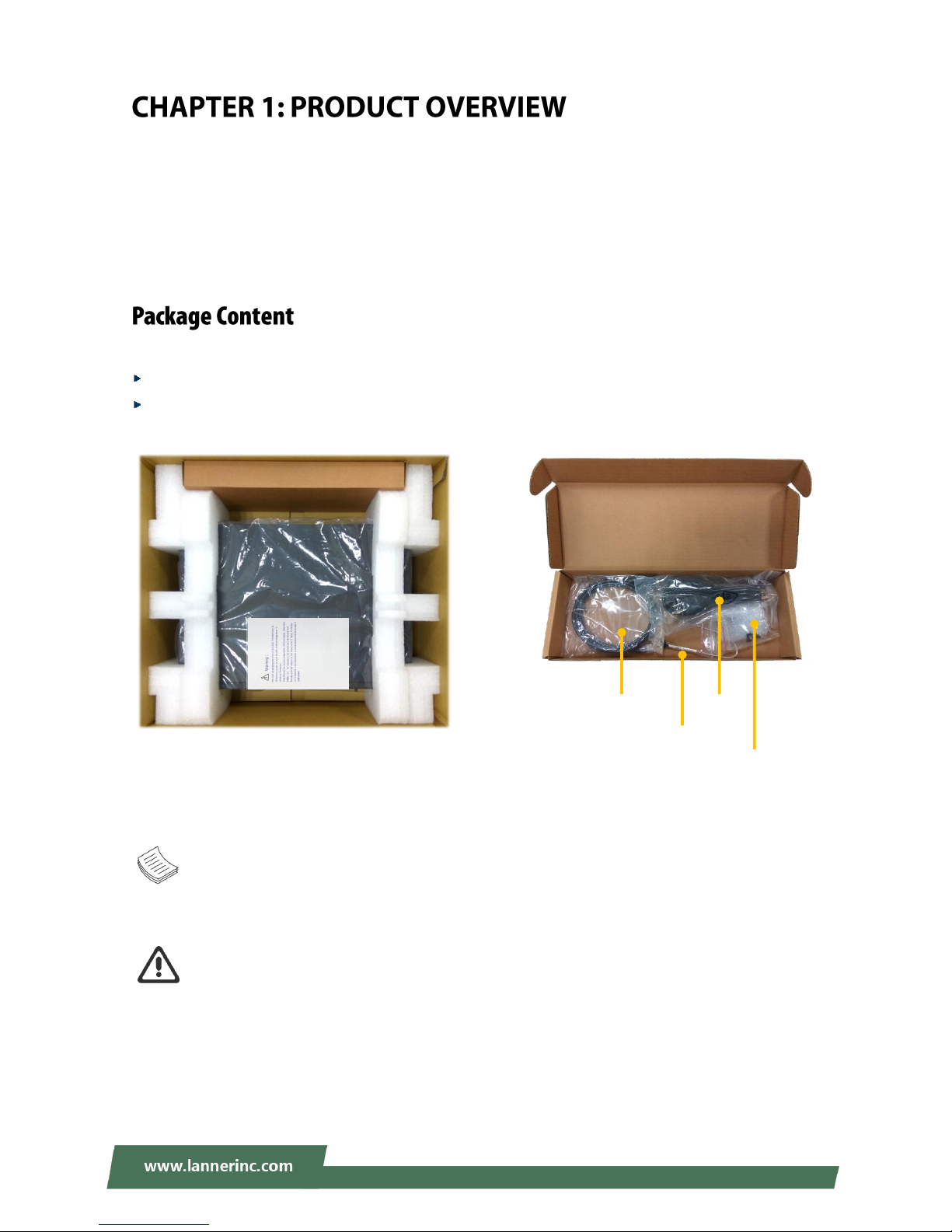
Your package contains the following items:
1x NCA-2510 Network Security Platform
1x Accessory Pack:
1x Power Cable, 1x Console Cable, 1x Mounting Ear Bracket Kit and 1x SATA Cable
Note: If you should find any components missing or damaged, please contact your dealer
immediately for assistance.
Warning: 1) The Harcuvar system can take up to 9 minutes from booting up to EFI shell in its first
initial. In the 2nd boot, 2 minutes is all it takes for a fast boot, which is considered normal for a
total of 32G DIMM. However, with higher capacity of DIMM used, the boot-up time gets longer.
2) After clearing CMOS or when PXE boot is enabled, the system boot-up time is doubled.
Console
Cable
SATA
Cable
Power
Cable
Mounting Ear
Bracket Kit
Accessory Pack
NCA-2510
Page 11
Chapter 1: Product Overview
11
SKU No.
NCA-2510 A
Intel C3958 16 Core with QAT + 5x GbE + 4x SFP+, 1x NIC (1x PCIex8/4x PCIex2)
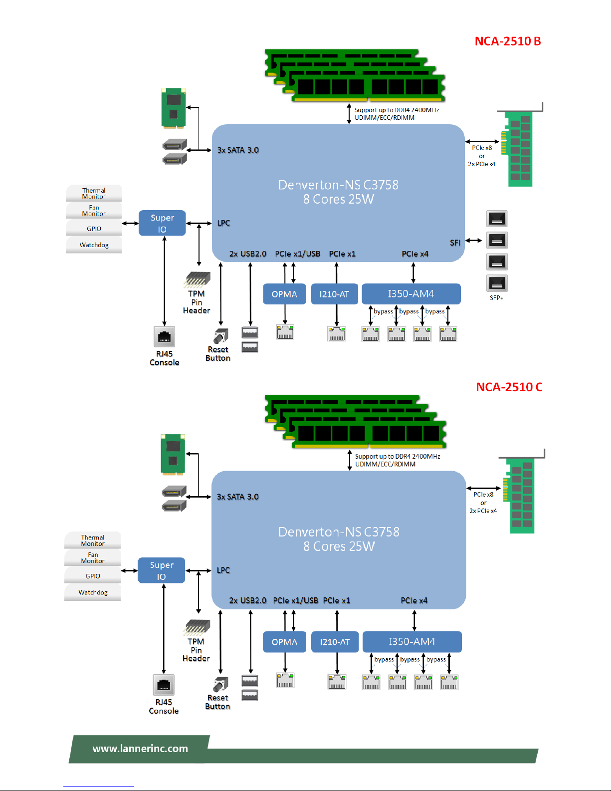
NCA-2510 B
Intel C3758 8 Core with QAT + 5x GbE + 4x SFP+, 1x NIC (1x PCIex8/2x PCIex4)
NCA-2510 C
Intel C3758 8 Core with QAT + 5x GbE, 1x NIC (1x PCIex8/2x PCIex4)
NCA-2510 D
Intel C3558 4 Core with QAT + 5x GbE
Model No.
Description
NCS2-IGM806A
8-port NIC with Intel i350 AM4 and 4pairs Gen3 Bypass
NCS2-ISM802A
8-port NIC with Intel i350-AM4 and No Bypass
NCS2-IXM407A
4-port 10GbE SFP with Intel Fortville XL710 Ethernet controller
NCS2-IXM409A
4-port 10GbE SFP with Intel Fortville XL710-BM1 Ethernet controller and Gen3
Bypass
IAC-AST2302
IPMI (Intelligent Platform Management Interface) Card with GbE management port
IAC-AST2302VGA
VGA card for network appliance to extend VGA display capability
IAC-TPM01C
TPM module supporting TPM2.0
RC-25103
Riser Card Kit for 1xPCIex8 HH/HL expansion (By SKU)
Console Cable
(for Main board)
D-SUB (DB9) to 10pin flat cable, 2.0mm Pitch, 55cm
VGA Cable
(for Main board)
VGA (DB15) to 12-pin flat cable, 2.54mm Pitch, 70cm
VGA Cable
(for IPMI card)
VGA (DB15) to 10-pin flat cable, 2.0mm Pitch, 65cm
SATA Cable
7-pin SATA latching cable with straight (180°-180°) connectors, 40cm
RJ45 Cable
A standard Category 5E cable supporting UTP, gray, 180cm
1U Slide Rail Kit
A pair of rails and 1x screw pack
Page 12
NCA-2510 User Manual
12
Form Factor
1U 19" Rackmount
Platform
Processor Options
Intel® Atom™ C3000 4/8/16 Cores
(Denverton)
CPU Socket
Onboard
Chipset
SoC
Security Acceleration
Intel® QuickAssist Technology
BIOS
AMI SPI Flash BIOS
System Memory
Technology
DDR4 2400MHz, REG/ECC/UDIMM
Max. Capacity
2/4/8/16/32GB
Socket
4x 288pin DIMM
Networking
Ethernet Ports
1x GbE RJ45 Intel® i210
4x GbE RJ45 Intel® i350-AM4
4x SFP+ Intel® Denverton Integrated
(By SKU)
Bypass
2X pairs Gen3 (By SKU)
NIC Module Slot
1
LOM
IO Interface
1x RJ45 (By SKU)
OPMA slot
Yes
I/O Interface
Reset Button
1
LED
Power/Status/Storage
Power Button
1x ATX Power switch
Console
1x RJ45
USB
2x USB 2.0
LCD Module
2x 20 character LCM, 4 x keypads
Display
From OPMA slot (Optional)
Power input
AC power inlet on PSU
Storage
HDD/SSD Support
2x 2.5” Bay
Onboard Slots
1x mSATA
Expansion
PCIe
1x PCIex8 HH/HL (By SKU)
mini-PCIe
N/A
Miscellaneous
Watchdog
Yes
Internal RTC with Li Battery
Yes
TPM
Yes (Optional)
Cooling
Processor
Passive CPU heatsink
System
2x cooling fan with smart fan
Environmental Parameters
Temperature
0 to 40ºC Operating
-20 to 70ºC Non-Operating
Humidity (RH)
5 to 90% Operating
5 to 95% Non-Operating
System Dimensions
(WxDxH)
438 x 321 x 44 mm
Weight
4.4 kg
Package Dimensions
(WxDxH)
540 x 500 x 230 mm
Weight
8 kg
Power
Type/Watts
150W ATX Single PSU
Input
AC 90~264V @47~63Hz
Approvals and Compliance
RoHS, CE/FCC Class A, UL,CB
Page 13
Chapter 1: Product Overview
13
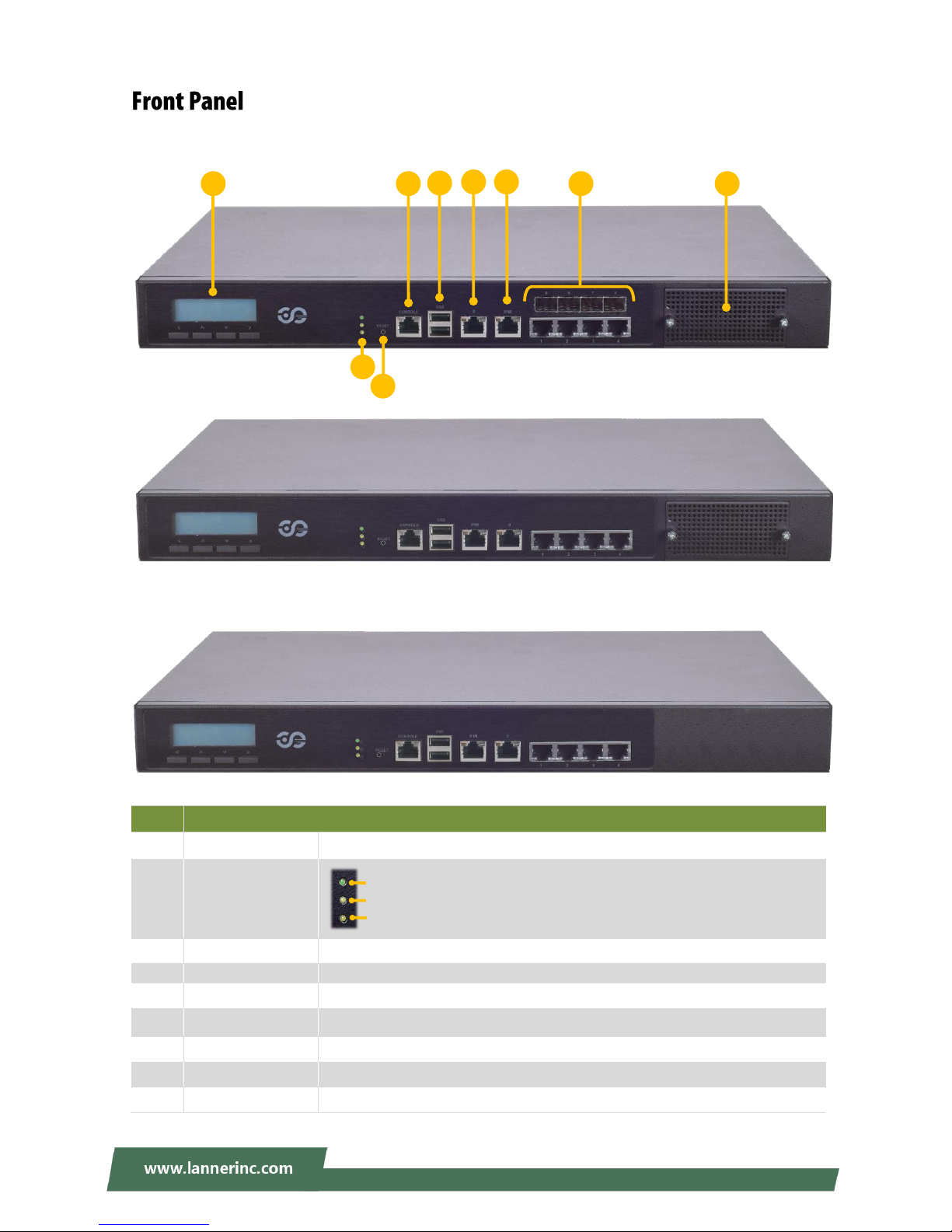
No.
Description
F1
LCM
With a Keypad
F2
LED Indicators
F3
Reset Button
Software reset
F4
Console Port
1x Console port
F5
USB Port
2x USB 2.0 port
F6
MGMT Port
1x Management port
F7
IPMI Port
1x RJ45 for IPMI (IPMI card required)
F8
GbE & SFP+ Ports
GbE ports: 1-4, SFP+ ports: 5-8 (by SKU)
F9
LAN Module
1x STD NIC module (by SKU)
F1
F8
F4
F5
F9
F2
F3
System Power
System Status
HDD Activity
F6
F7
NCA-2510A/B
NCA-2510 C
NCA-2510D
Page 14
NCA-2510 User Manual
14
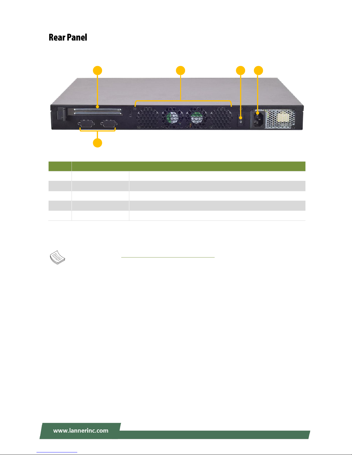
No.
Description
R1
Rear PCIe Expansion
1x PCIex8 Expansion slot (Riser card required)
R2
Console/VGA Port
2x reserved holes for Console/VGA cable
R3
Cooling Fans
2x swappable independent fan
R4
Power Button
1x ATX Power button
R5
Power Supply
1x 150W PSU
Note: Please refer to Appendix A: LED Indicator Explanations for description of the LED Indicators
R4
R3
R1
R5
R2
NCA-2510A/B/C/D
Page 15

Chapter 2: Motherboard Information
15
The block diagram indicates how data flows among components on the motherboard. Please refer to the
following figure for your motherboard’s layout design.
Page 16
NCA-2510 User Manual
16
Page 17

Chapter 2: Motherboard Information
17
Page 18
NCA-2510 User Manual
18
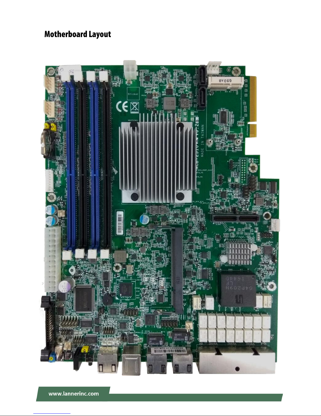
The motherboard layout shows the connectors and jumpers on the board. Refer to the following picture as
a reference of the pin assignments and the internal connectors.
A
A
A
T
T
T
X
X
X
2
2
2
J
J
J
S
S
S
A
A
A
T
T
T
A
A
A
2
2
2
J
J
J
S
S
S
A
A
A
T
T
T
A
A
A
1
1
1
F
F
F
A
A
A
N
N
N
2
2
2
F
F
F
A
A
A
N
N
N
1
1
1
A
A
A
T
T
T
X
X
X
1
1
1
J
J
J
C
C
C
M
M
M
O
O
O
S
S
S
1
1
1
J
J
J
R
R
R
T
T
T
C
C
C
1
1
1
J
J
J
L
L
L
C
C
C
M
M
M
1
1
1
S
S
S
W
W
W
1
1
1
S
S
S
W
W
W
3
3
3
C
C
C
O
O
O
N
N
N
N
N
N
2
2
2
J
J
J
2
2
2
1
1
1
J
J
J
T
T
T
P
P
P
M
M
M
1
1
1
J
J
J
8
8
8
0
0
0
P
P
P
O
O
O
R
R
R
T
T
T
1
1
1
C
C
C
O
O
O
M
M
M
B
B
B
2
2
2
J
J
J
P
P
P
L
L
L
D
D
D
1
1
1
J
J
J
O
O
O
P
P
P
M
M
M
A
A
A
1
1
1
J
J
J
V
V
V
G
G
G
A
A
A
1
1
1
J
J
J
1
1
1
0
0
0
J
J
J
9
9
9
J
J
J
P
P
P
M
M
M
B
B
B
U
U
U
S
S
S
2
2
2
J
J
J
G
G
G
P
P
P
1
1
1
J
J
J
R
R
R
E
E
E
S
S
S
E
E
E
T
T
T
1
1
1
J
J
J
O
O
O
P
P
P
E
E
E
N
N
N
1
1
1
Page 19
Chapter 2: Motherboard Information
19
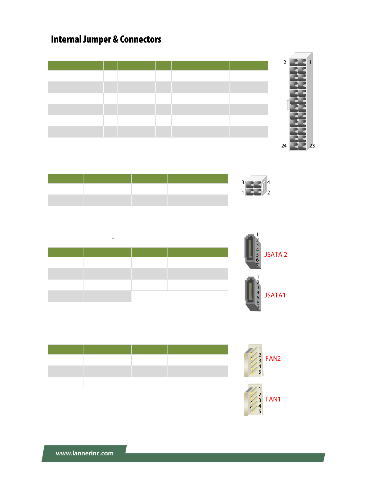
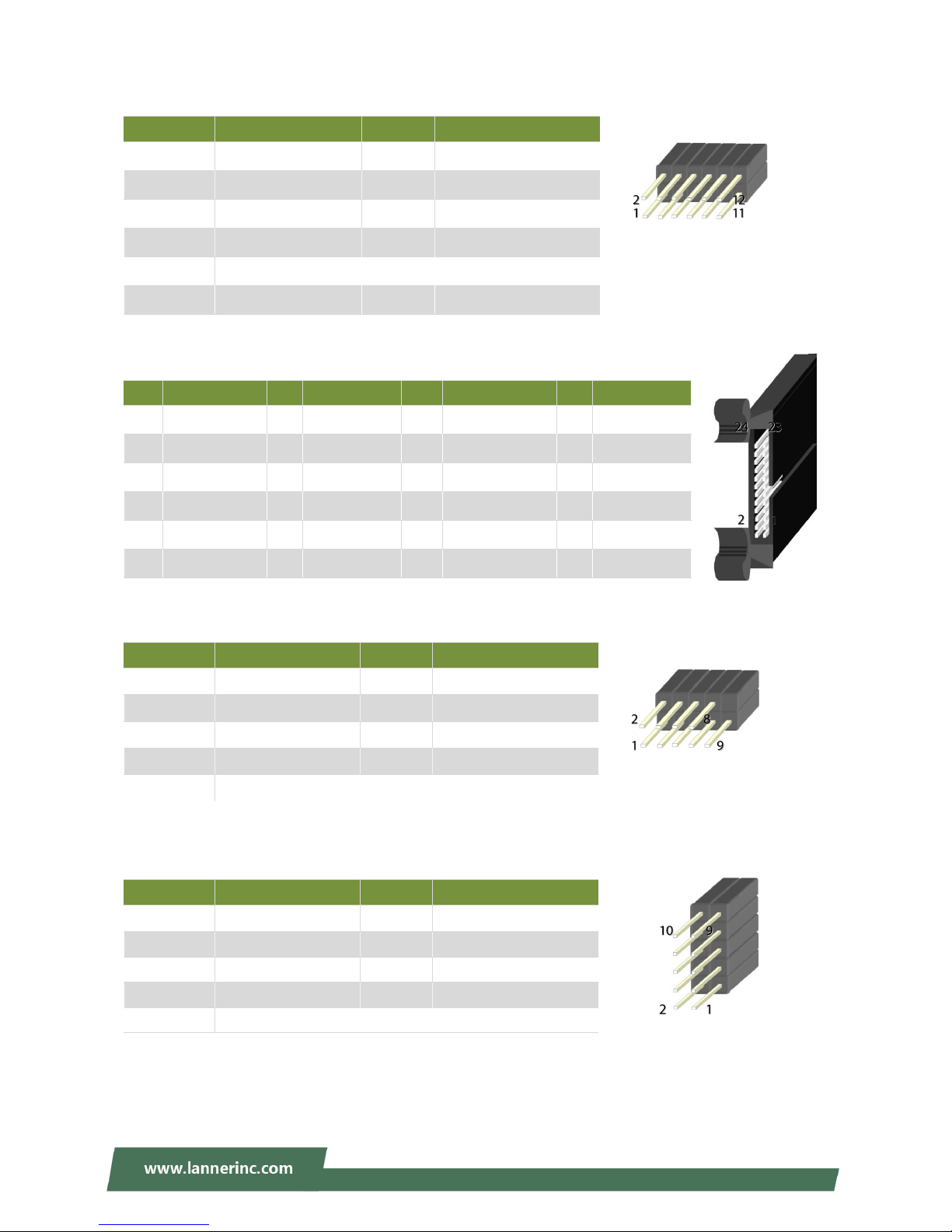
ATX1: 24-Pin ATX Power Connector
ATX2: 4-pin Power Connector
JSATA2 & JSATA1: 180° SATA Connector (with SATA DOM)
FAN1-2: Fan Connector
Pin
Description
Pin
Description
Pin
Description
Pin
Description
1
+3.3V
2
+3.3V
3
+3.3V
4
-12V
5
Ground
6
Ground
7
+5V
8
PSON-
9
Ground
10
Ground
11
+5V
12
Ground
13
Ground
14
Ground
15
Power Good
16
NC
17
Stand-By 5V
18
+5V
19
+12V
20
+5V
21
+12V
22
+5V
23
3.3V
24
Ground
Pin
Description
Pin
Description
1
GND 2 +12V
3
GND 4 +12V
Pin
Description
Pin
Description
1
GND 2 TX+
3
TX- 4 GND
5
RX-
6
RX+
7
SATA Power
Pin
Description
Pin
Description
1
GND 2 12V
3
RPM Sense
4
RPM Sense
5
PWM Status
Page 20
NCA-2510 User Manual
20
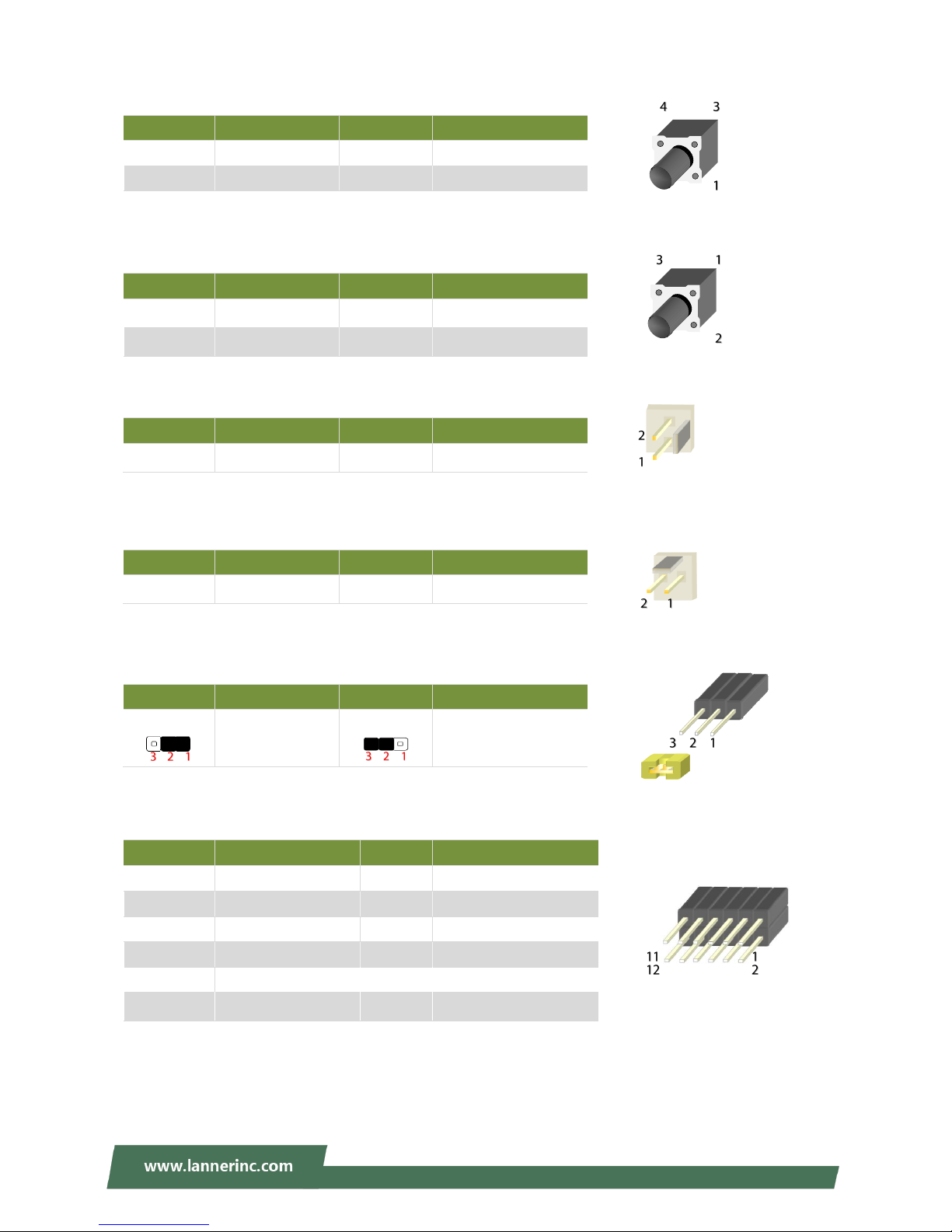
SW3: Reset Switch (reserved for debugging)
SW1: PSON power switch (reserved for debugging)
J21: Reset
CONN2: PSON power
JRESET1: Controls the software reset method of the Reset button on front panel.
VGA1: VGA
Pin
Description
Pin
Description
1
GND 2 GND
3
FP_RST_SEL
4
FP_RST_SEL
Pin
Description
Pin
Description
1
GND 2 GND
3
FP_SWIN_R
4
FP_SWIN_R
Pin
Description
Pin
Description
1
GND
2
FP_SWIN_R
Pin
Description
Pin
Description
1
GND
2
FP_SWIN_R
Pin
Description
Pin
Description
1.2
HW reset
2.3
SW reset
(Default)
Pin
Description
Pin
Description
1 R 2
Ground
3 G 4
Ground
5 B 6
Ground
7
H-SYNC
8
Ground
9
V-SYNC
10
Ground
11
Detect-display Data
12
Detect-display CLOCK
Page 21
Chapter 2: Motherboard Information
21
JTPM1: TPM
JLCM1: LCM
COMB2: COM PORT
JGP_1: GPIO
Pin
Description
Pin
Description
1
LPC_SERIRQ
2
SOC_LPC_FRAME_N
3
SOC_LPC_LAD0
4
CLK_LPC_OUT
5
SOC_LPC_LAD1
6
P3V3_STBY
7
SOC_LPC_LAD2
8
NC
9
SOC_LPC_LAD3
10
P3V3_A
11
CPLD_TPM_RESET_N
12
Ground
Pin
Description
Pin
Description
Pin
Description
Pin
Description
1
VCC
2
IOGND
3
LSTIN
4
VEE
5
LAFD
6
LINIT
7
LPD1
8
LPD0
9
LPD3
10
LPD2
11
LPD5
12
LPD4
13
LPD7
14
LPD6
15
LCD
16
VCC
17
K1
18
K2
19
K3
20
K4
21
GND
22
VCC3
23
GPIO
24
VCC3
Pin
Description
Pin
Description
1
NDCD
2
NDSR
3
NRXD 4 NRTS
5
NTXD 6 NCTS
7
NDTR 8 NRI
9
GND
Pin
Description
Pin
Description
1 R 2
Ground
3 G 4
Ground
5 B 6
Ground
7
H-SYNC
8
Ground
9
V-SYNC
10
Ground
Page 22
NCA-2510 User Manual
22
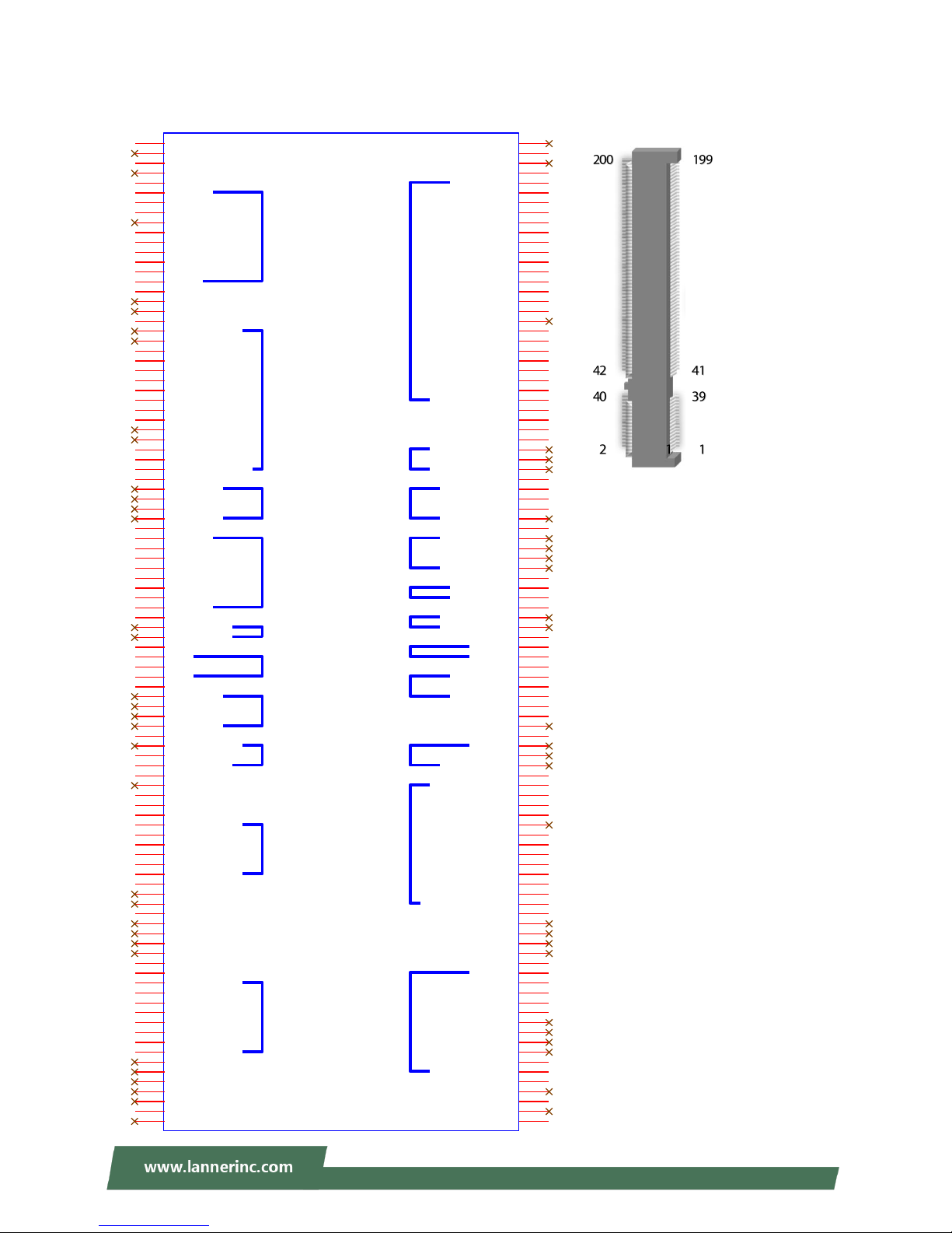
JOPMA1: OPMA
LPC
I2C
Debug
UART
Debug
ID
Debug
Control
Analog
Sensor
Power
DVI-I
FAN
FAN
FAN
SOL
LED
USB
Button
ICMB
LAN
Status
OPMA
CON7
OPMA
GND
1
RSVD
3
GND
5
RSVD
7
GND
9
LDRQ_L
11
LFRAME_L
13
LAD0
15
LCLKRUN_L
17
LAD1
19
LAD2
21
LAD3
23
SERIRQ
25
LRST_L
27
LCLK
29
GND
31
RSVD
33
RSVD
35
GND
37
I2C_PRIV0_SCL
39
I2C_PRIV0_SDA
41
GND
43
I2C_IPMB_SCL
45
I2C_IPMB_SDA
47
GND
49
I2C_SB_NIC_SCL
51
I2C_SB_NIC_SDA
53
I2C_SB_NIC_ALERT
55
GND
57
I2C_PRIV1_SCL
59
I2C_PRIV1_SDA
61
GND
63
I2C_SHARED_SCL
65
I2C_SHARED_SDA
67
GND
69
DEBUG_IF0
71
DEBUG_IF1
73
DEBUG_IF2
75
DEBUG_IF3
77
GND
79
DTR0_L
81
DCD0_L
83
DSR0_L
85
RI0_L
87
RXD0
89
TXD0
91
CTS0_L
93
RTS0_L
95
GND
97
DEBUG_PWR0
99
DEBUG_PWR1
101
GND
103
ID0
105
ID1
107
ID2
109
GND
111
DEBUG_IF4
113
DEBUG_IF5
115
DEBUG_IF6
117
DEBUG_IF7
119
GND
121
LOCAL_LOCK_L
123
SYS_SPKR_DATA
125
CLR_CMOS_L
127
GND
129
CLK_32768
131
GND
133
DETECT_L
135
GND
137
ACOMP_ADC0
139
ACOMP_ADC1
141
ACOMP_ADC2
143
ACOMP_ADC3
145
ACOMP_ADC4
147
ACOMP_ADC5
149
GND
151
SCI_INT_L
153
RSVD
155
GND
157
RSVD
159
RSVD
161
RSVD
163
RSVD
165
GND
167
GND
169
VDD_3.3_DUAL
171
VDD_3.3_DUAL
173
VDD_3.3_DUAL
175
VDD_3.3_DUAL
177
GND
179
GND
181
VDD_5_DUAL
183
VDD_5_DUAL
185
RSVD
187
RSVD
189
RSVD
191
RSVD
193
RSVD
195
GND
197
RSVD
199
RSVD
2
GND
4
RSVD
6
GND
8
DVI_TX0_H
10
DVI_TX0_L
12
GND
14
DVI_TX1_H
16
DVI_TX1_L
18
GND
20
DVI_TX2_H
22
DVI_TX2_L
24
GND
26
DVI_TXCLK_H
28
DVI_TXCLK_L
30
GND
32
DVI_DDC_DATA
34
DVI_DDC_CLK
36
RSVD
38
ANALOG_DDC_DATA
40
ANALOG_DDC_CLK
42
GND
44
ANALOG_RED
46
ANALOG_GREEN
48
ANALOG_BLUE
50
ANALOG_HSYNC
52
ANALOG_VSYNC
54
GND
56
RSVD
58
RSVD
60
GND
62
FAN_PWM_CPU
64
FAN_PWM_SYS
66
FAN_PWM_PS
68
GND
70
FAN_TACH0
72
FAN_TACH1
74
FAN_TACH2
76
FAN_TACH3
78
GND
80
FAN_SEL0_L
82
FAN_SEL1_L
84
FAN_SEL2_L
86
FAN_SEL3_L
88
GND
90
RXD_SOL
92
TXD_SOL
94
GND
96
FAULT_LED_L
98
CHASSIS_ID_L
100
GND
102
USB_P
104
USB_N
106
GND
108
PWRBTN_L
110
RSTBTN_L
112
NMIBTN_L
114
GND
116
AUX_SOL_CTRL_L
118
RSVD
120
GND
122
RXD1
124
TXD1
126
TXD1_ENABLE
128
GND
130
ALL_PWROK
132
SYS_THERMTRIP_L
134
SYS_INTRUDER_L
136
SYS_LINE_AC_L
138
SYS_PWRBTN_L
140
SYS_RSTBTN_L
142
SYS_NMIBTN_L
144
SYS_SMI_L
146
SYS_PCI_RST
148
SYS_ACPI_STATE0
150
SYS_ACPI_STATE1
152
SYS_ACPI_STATE2
154
SYS_IO_EXT_INT_L
156
GND
158
RSVD
160
RSVD
162
RSVD
164
RSVD
166
GND
168
TX_H
170
TX_L
172
GND
174
RX_H
176
RX_L
178
POE_GND
180
POE_PWR
182
POE_PWR
184
POE_GND
186
LAN_BUSY_LED_L
188
LAN_LINK_LED_L
190
GND
192
RSVD
194
GND
196
RSVD
198
GND
200
Page 23
Chapter 2: Motherboard Information
23
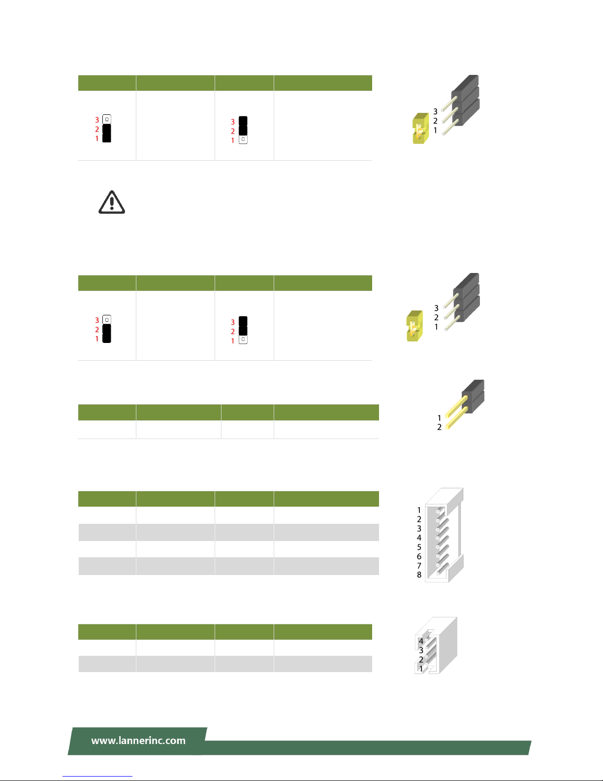
JCMOS1: Clear CMOS
Warning: After clearing CMOS or when PXE boot is enabled, the system boot-up time is
doubled.
JRTC1: RTC
JOPEN1: Case open
JPMBUS2
J10: Gen3 Bypass Firmware Update
Pin
Description
Pin
Description
1.2
Normal (Default)
2.3
Clear CMOS
Pin
Description
Pin
Description
1.2
Normal (Default)
2.3
Clear RTC
Pin
Description
Pin
Description
1
GND
2
CSOPEN_N
Pin
Description
Pin
Description
1
RDPW_TTL1
2
RDPW_TTL2
3
NC 4 GND
5 6
SMB_PS_CLK
7
SMB_PS_DATA
8
NC
Pin
Description
Pin
Description
1
GND 2 TX_P
3
TX_M 4 GND
Page 24
NCA-2510 User Manual
24
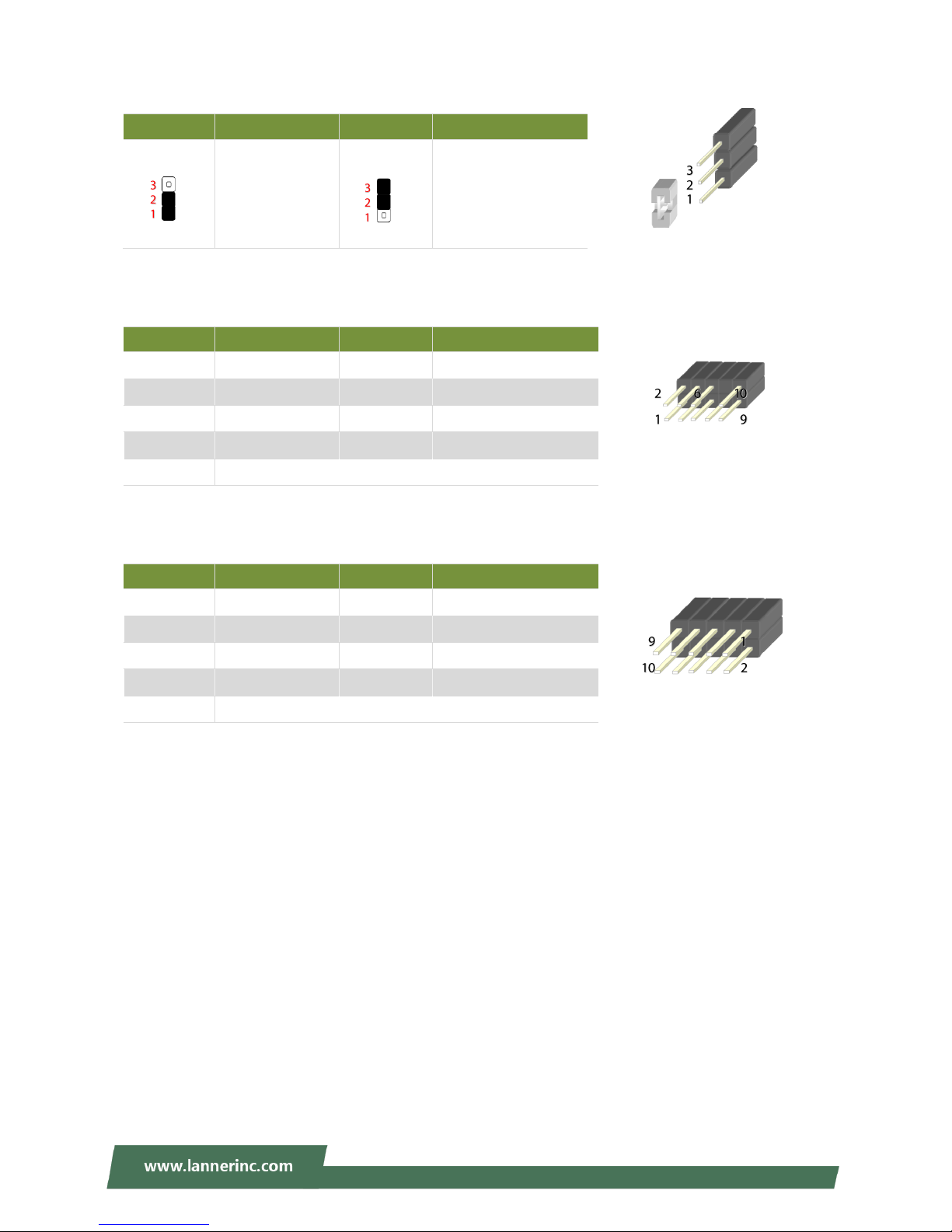
J9: Gen3 Bypass Firmware Update
J80PORT1: 80Port Debug
JPLD1: Altera CPLD
Pin
Description
Pin
Description
1.2
Normal (Default)
2.3
Firmware Update
Pin
Description
Pin
Description
1
CLK 2 LAD1
3
RST- 4 LAD0
5
LRAME-
6
POWER
7
LAD3 8
9
LAD2
10
GND
Pin
Description
Pin
Description
1
JTAG_PLD_TCK
2
GND
3
JTAG_PLD_TDO
4
P3V3_STBY
5
JTAG_PLD_TMS
6
NC
7
NC 8 NC
9
JTAG_PLD_TDI
10
GND
Page 25

Chapter 3: Hardware Setup
25
To reduce the risk of personal injury, electric shock, or damage to the system, please remove all power
connections to completely shut down the device. Also, please wear ESD protection gloves when conducting
the steps narrated in this chapter.
1. Loosen the two thumb screws from
the rear panel of NCA-2510.
2. Gently pull the cover backward a
bit.
3. Lift the cover up to remove it.
3
1
1
2
Page 26

NCA-2510 User Manual
26
NCA-2510 is built with two 2.5” HDD/SSD slot drive bays. The following will discuss disk drive installation
procedures based on their HDD/SSD designs.
1. Locate the 2.5” disk bay area in the
chassis.
2. Loosen the only screw that secures
the HDD tray.
3. Slide the tray towards the direction
shown in the picture to entirely
unlock it from the latching spots at
four corners.
1 2 3
Unlocked
Locked
Page 27

Chapter 3: Hardware Setup
27
4. Take out the HDD tray.
5. Slide the disks into the tray. Make
sure the disk connector faces the
direction as the picture shows.
6. To mount the disks onto the empty
tray, secure them on the tray with
two disk screws locked on each side
of the disk.
7. Have the cable ends go under and
pass through the CPU dusk cover and
then insert one end of the SATA data
cable into the SATA connector on the
motherboard. You can temporarily
unscrew the bolts that fix the dusk
cover for easier operation.
4 5 6
SATA
Contacts
Disk
Screws
Disk
Screws
7
Dust Cover
SATA2
SATA1
Page 28

NCA-2510 User Manual
28
8. Insert the other end of the SATA
cable into the disk and connect the
end of SATA power cable with the
disk. The SATA connection between a
disk and the system is now built up.
Repeat Step 7~8 to establish the
SATA connection of the other disk.
9. Reverse the procedures narrated in
Step 3 and then secure the tray to
the chassis. Arrange the cables and
route them neatly to avoid them
from getting tangled.
8
9
Page 29

Chapter 3: Hardware Setup
29
The NCA-2510 provides one OPMA slot for installing the IPMI card. Follow these procedures below for
installing an IPMI card.
1. Locate the OPMA socket.
2. Align the notch of the card with the
socket key in the slot.
3. Insert the module at 30 degrees into
the socket until it is fully seated in the
connector.
4. Press on two corners of the card to
push it down vertically until it clicks
into place.
Socket Key
2 3 4
1
Notch
Page 30

NCA-2510 User Manual
30
5. Secure the card with a screw that
comes with it.
To remove the card, loosen the screw that secures it to the motherboard, push aside the two metal leaves
that hold the card to release it from the socket before you can pull it out.
5
Page 31

Chapter 3: Hardware Setup
31
NCA-2510 comes with 1 NIC Ethernet module slot for network bandwidth expansion. Please follow the
steps for installation.
1. Rotate the two lock-screws
counterclockwise and loosen them.
2. Remove the door and locate the PCIe
slot for module insertion.
3. Insert your NIC Ethernet module.
(The module shown in the image
below is for reference only).
2
PCIe Slot
Align the gold fingers to the PCIe slot
on the motherboard carefully while
inserting this module.
1
3
Page 32

NCA-2510 User Manual
32
4. Once the module is firmly seated,
rotate clockwise and tighten the two
lock-screws.
4
Page 33

Chapter 3: Hardware Setup
33
The motherboard provides one mSATA slot. Follow the procedures below for installing an mSATA card.
1. Locate the mSATA slot.
2. Align the notch of the module with the
socket key in the slot.
3. Insert the module at 30 degrees into
the socket until it is fully seated in the
connector.
4. Press down on the module and secure
it with screws that come with it.
Notch
Socket
Key
2
3
4
1
Page 34

NCA-2510 User Manual
34
The motherboard supports DDR4 registered DIMM memory for heavy-duty operations. Please follow the
steps below to install the DIMM memory modules.
1. Locate the the DIMM slot.
2. Pull open the DIMM slot latches.
3. Align the notch of the DIMM module
with the socket key in the slot.
4. Push the module on its both corners
into the slot until it is firmly seated.
The latches will automatically snap
locked.
Warning: The Harcuvar system
can take up to 9 minutes from
booting up to EFI shell in its first initial.
In the 2nd boot, 2 minutes is all it takes
for a fast boot, which is considered
normal for a total of 32G DIMM.
However, with higher capacity of DIMM
used, the boot-up time gets longer.
4
Notch
Socket Key
2
2 3 4
1
Page 35

Chapter 3: Hardware Setup
35
To install a PCIe expansion card onto the motherboard with a Riser Card, please purchase the Riser Card kit
from Lanner and have the PCIe expansion card you want to install ready.
1. Power off this system and remove the
system cover. Locate the PCIe Expansion
Slot.
2. Loosen the only screw that secures the
PCIe slot cover.
3. Slide the cover towards the direction
shown in the picture to entirely release it
from the latching spot.
1
Unlocked
Latched
Released
2
3
Page 36

NCA-2510 User Manual
36
4. Remove the original Riser Card.
5. Unbox your Riser Card Kit which
contains a Riser Card, two Brackets and
screws.
6. Assemble the Riser Card and Bracket A
with four screws.
7. Install your PCIe Expansion Card into the
Bracket assembly as shown in the
picture by carefully inserting the
connector into the Riser Card.
Riser Card Bracket A
4 5 7
PCIe Expansion Card Bracket A
6
Grip
Bracket B (for FH/FL
size PCIe Expansion
Card)
Riser Card
Page 37

Chapter 3: Hardware Setup
37
8. From the inner side, insert the side of
the PCIe Expansion card with the
meshed metal slot cover into the chassis,
with the holder stuck out from inside.
9. Install the Bracket assembly into the
PCIe connector on the motherboard.
Ensure that the golden connectors of
the Bracket are firmly seated in place.
10. On the rear panel, use a screw to
secure the slot Cover Bracket and the
Grip onto the chassis.
11. To accommodate a FH/FL-sized PCIe
Expansion card, please also fix Bracket B
in the chassis using two screws in order
to support the PCIe Expansion Card.
8
10
8
Make sure the Grip is stuck out
9
Slot Cover Bracket
Bracket B
Grip
Page 38

NCA-2510 User Manual
38
There are two methods for installing this system into a rack:
With Mounting Ear Brackets only
This method is quick and easy by fixing this system to the front posts of the rack, but it also makes servicing
the system more difficult. Please note that the use of these brackets must go with a rack shelf or slide rails
to prevent the chassis from falling over, for the bracket assembly alone cannot provide sufficient support to
the chassis.
With Slide Rail Kit + Mounting Ear Brackets
This method is rather complicated, but the slidable rails allow you to access the system easily, while
securing it in the rack solidly.
The system shall be installed on the rack along with a shelf or slide rails, for the “Mounting Ears" are meant to secure
the system, not to support it.
The Slide Rail Kit can
secure the system while
providing sufficient weight
support for the device.
Page 39

Chapter 3: Hardware Setup
39
1. Check the accessory pack for the following
items:
1x Screw Pack
2x Ear Brackets
2. Align the bracket to the side of the chassis and
make sure the screw-holes are matched, and
then secure the bracket onto the chassis with
three provided screws.
3. Repeat Step 2 to attach the bracket to the other
side of the chassis.
4. Install the chassis into the rack with the brackets
fixed onto the posts using the provided screws.
The actual approach you adopt and the needed
parts for assembly will depend on the
supporting accessory (shelf or rail kit) you use.
.
Page 40

NCA-2510 User Manual
40
1. Check the package contents of the
Slide Rail Kit. The kit shall include
the following items:
1x pack of M4X4L screws (for
securing the Rail Brackets on the
system)
1x pack of 7.1 Round Hole
screws (for securing the system on
the rail posts)
2x Slide Rails
A rail consists of the following parts:
2. Unpack a slide rail and slide the
Inner Rail all the way to the end.
3. Stretch the bracket to the fullest.
4. Remove the bracket from the Inner
Rail by pushing the Release Tab on
the bracket outwards while sliding
it out.
Outer Rail
Inner Rail
Release Tab
Rail Lock
Release Tab
Rail Bracket
Rail Bracket
Page 41

Chapter 3: Hardware Setup
41
5. Align the bracket to the side of the
chassis and make sure the
screw-holes are matched, and then
secure the bracket onto the chassis
with three provided M4X4L screws.
6. Repeat Steps 2~5 to attach the bracket to the other side of the chassis.
7. Follow the instructions in Installing the System Using Mounting Ear Brackets Only to attach the
Mounting Ear Brackets.
Now, you shall install the slide rail
assemblies onto the rack.
8. This slide-rail kit does NOT require
screw-fixing. Simply aim at three
available screw holes on the rack
front and snap the rail front into the
rack post as shown in the image.
You should hear a “click” sound
once it is firmly attached.
Align the screws with the holes indicated on the brackets and the
screw holes on the side of the chassis.
Left Rail Bracket
Right Mounting
Ear Bracket
Right Rail Bracket
Use this clamp
to fix the front
end of the rail
onto the post.
Click
Left Mounting
Ear Bracket
Page 42

NCA-2510 User Manual
42
9. For the rear rack installation, slide
the rail to aim and engage the bolts
on the rail’s rear end with the two
available holes on the post, and the
rail assembly will click into place.
10. Stretch both of the Inner Rails out
to their fullest extent. You will
hear a click sound when they are
fully stretched and locked.
11. Hold the system with its front
facing you, lift the chassis and
gently engage the brackets on
the system while aligning them
with the Inner Rails as shown in
the image, and then push the
system into the cabinet.
The Inner Rail will click
when it is fully stretched.
Click
Click
Page 43

Chapter 3: Hardware Setup
43
12. While pushing in the system, also
push and hold the Rail Lock tab
on both brackets.
Push the system all the way in until
it stops.
To remove the system from the rack,
gently pull it outwards towards you
while pushing the Release Tab on both
sides of the brackets.
Rail Lock
Release Tab
Page 44

NCA-2510 User Manual
44
To enter the BIOS setup utility, simply follow the steps below:
1. Boot up the system.
2. Press <Delete> during the boot-up if you connect a keyboard to this unit. But if you connect a PC to
this unit through console USB/Serial connection, then press <Tab>. Your system should be running
POST (Power-On-Self-Test) upon booting up.
3. Then you will be directed to the BIOS main screen.
4. Instructions of BIOS navigations:
Control Keys
Description
select a setup screen, for instance, [Main], [IntelRCSetup], [Security], [Boot], and
[Save & Exit]
select an item/option on a setup screen
<Enter>
select an item/option or enter a sub-menu
+/-
to adjust values for the selected setup item/option
F1
to display General Help screen
F2
to retrieve previous values, such as the parameters configured the last time you
had entered BIOS.
F3
to load optimized default values
F4
to save configurations and exit BIOS
<Esc>
exit the current screen
Page 45

Chapter 4: BIOS Setup
45
Setup main page displays a description of BIOS information and project version information. You can also
setup the System Time and System Date here.
(The screenshots presented in section are for reference only)
Page 46

NCA-2510 User Manual
46
Use [←] [→] to select [Advanced] setup screen. Under this screen, you may use [↑] [↓] to select an item you
want to configure.
Page 47

Chapter 4: BIOS Setup
47
This option allows you to configure parameters about BIOS support for the security device. Press <Enter>
to access the submenu. The default is “Enabled”.
Page 48

NCA-2510 User Manual
48
This option allows you to configure parameters about Super IO Chip. Press <Enter> to access the
submenu.
Select Serial Port 1 Configuration or Serial Port 2 Configuration to enter sub setting screen. The default
is “Enabled”.
Page 49

Chapter 4: BIOS Setup
49
This option allows you to configure Smart Fan properties and monitor the fan status.
Page 50

NCA-2510 User Manual
50
Enter “Smart Fan Control” to change fan mode. The default is “Smart Fan Mode”.
Page 51

Chapter 4: BIOS Setup
51
If with the case’s support, enabling this option will have the unit sound when someone opens the case of
this unit, which is considered against your organization’s policy. The default is “Disabled”.
Page 52

NCA-2510 User Manual
52
This option allows you to configure Digital I/O pin properties. Select the desired pin and press <Enter> to
modify. The default is “Output Low”.
Page 53

Chapter 4: BIOS Setup
53
This option allows you to enable or disable Watchdog Timer function. The default is “Disabled”.
Page 54

NCA-2510 User Manual
54
This option allows you to configure parameters about serial port console redirection. Press <Enter> to
access the submenu. The default is “Enabled”.
Page 55

Chapter 4: BIOS Setup
55
Console Redirection Settings
Select this item to enter the setting sub-menu. These settings specify how the host computer and the
remote computer will exchange data. Both computers should have the same or compatible settings.
Item
Value
Description
Terminal Type
VT100
VT100+
VT-UTF8
ANSI
VT100: ASCII char set.
VT100+: Extends VT100 to support color,
function keys, etc.
VT-UTF8: Uses UTF8 encoding to map
Unicode chars onto 1 or more bytes.
ANSI: Extended ASCII char set.
Bits per second
9600
19200
38400
57600
115200
Selects serial port transmission speed. The
speed must be matched on the other side.
Long or noisy lines may require lower speeds.
Data Bits
7
8
Data Bits
Parity
None
Even
Odd
Mark
Space
A parity bit can be sent with the data bits to
detect some transmission errors.
Stop Bits
1
2
Stop bits indicate the end of a serial data
packet.
Flow Control
None
Hardware RTS/CTS
Flow control can prevent data loss from
buffer overflow.
Page 56

NCA-2510 User Manual
56
VT-UTF8 Combo Key
Support
Disabled
Enabled
Enable VT-UTF8 Combination Key Support for
ANSI/VT100 terminals
Recorder Mode
Disabled
Enabled
With this mode enabled only text will be sent.
This is to capture Terminal data.
Putty KeyPad
VT100
LINUX
XTERM86
SCO
ESCN
VT400
Select FunctionKey and KeyPad on Putty.
Page 57

Chapter 4: BIOS Setup
57
This option allows you to configure parameters to be programmed into PCI Latency Timer Register.
Page 58

NCA-2510 User Manual
58
PCI Express Settings
This option allows you to enable or disable PCI Express Device Relaxed Ordering.
Page 59

Chapter 4: BIOS Setup
59
PCI Express GEN 2 Settings
This option allows you to enable or disable PCI ExpressGEN2 related setting.
Page 60

NCA-2510 User Manual
60
This option allows you to enable or disable UEFI Network Stack. The default is “Disabled “.
Page 61

Chapter 4: BIOS Setup
61
This option allows you to enable or disable ROM execution settings.
Item
Value
Description
CSM Support
Disabled
Enabled
Enables or disables CSM Support
Network
Do Not Launch
UEFI
Legacy
Controls the execution of UEFI and
Legacy PXE OpROM
Storage
Do Not Launch
UEFI
Legacy
Controls the execution of UEFI and
Legacy Storage OpROM
Video
Do Not Launch
UEFI
Legacy
Controls the execution of UEFI and
Legacy Video OpROM
Other PCI device
Do Not Launch
UEFI
Legacy
Determines OpROM execution policy for
devices other than Network, Storage, or
Video
Page 62

NCA-2510 User Manual
62
This option allows you to change USB configuration parameters.
Legacy USB Support
Item
Value
Description
Legacy USB Support
Enabled
Disabled
Auto
Enables Legacy USB support.
“Auto“ disables legacy support if no USB
devices are connected. “Disabled“ will
keep USB devices available only for EFI
applications. The default is “Enabled “.
XHCI Hand-off:
Enabled
Disabled
This is a workaround for QSes without
XHCI hand-off support. The XHCI
ownership change should be claimed by
XHCI driver. The default is “Enabled “.
USB Mass Storage
Driver Support: “.
Enabled
Disabled
Enables or disables USB Mass Driver
Support. Default is “Enabled”.
Port 60/64 Emulation:
Enabled
Disabled
This option enables I/O port 60h/64h
emulation support. This should be
enabled for the complete USB keyboard
legacy support for non-USB aware
operating systems. The default is
“Enabled “.
Page 63

Chapter 4: BIOS Setup
63
USB transfer time-out
1 sec
5 sec
10 sec
20 sec
Set USB time-out value (1, 5, 10 or 20
seconds) for Control, Bulk and Interrupt
transfers. The default is “20 sec “.
Device reset time-out:
10 sec
20 sec
30 sec
40 sec
Set USB mass storage device Start Unit
command time-out (10, 20, 30 or 40
seconds). Default is “20 sec “.
Device power-up
delay
Auto
Manual
Set the maximum time the device will
take before it properly reports itself to
the Host Controller. “Auto“ uses default
value. For example, it is 100ms as a root
port.
Page 64

NCA-2510 User Manual
64
Use [←] / [→] to select the Chipset menu item from the BIOS setup screen to enter the IntelRCSetup Setup
screen. Users can select any of the items in the left frame of the screen.
Page 65

Chapter 4: BIOS Setup
65
Item
Value
Description
EIST(GV3)
Disable
Enabled
Enables or disables EIST. GV3 and TM1
must be enabled for TM2 to be available.
GV3 must be enabled for Turbo. Auto Enable for B0 CPU stepping, all others
disabled, change setting to override.
CPU C State
Disabled
Enabled
Enables the Enhanced Cx state of the
CPU, takes effect after reboot. Auto Enable for B0 CPU stepping, all others
disabled, change setting to override.
Page 66

NCA-2510 User Manual
66
Page 67

Chapter 4: BIOS Setup
67
This option enables or disables fast boot which skips memory training and attempts to boot using last
known good configuration. The default is “Enabled”.
Page 68

NCA-2510 User Manual
68
This option allows you to configure SATA Controller properties.
SATA Configuration Enables/Disables SATA Controller if supported by current CPU SKU. The default is
“Enabled”. Enabling the SATA controller, you can respectively modify the JSATA1, JSATA1 and mSATA
properties.
Page 69

Chapter 4: BIOS Setup
69
Use [←] [→] to select Security setup screen. Under this screen, you may use [↑] [↓] to select an item you
would like to configure.
Administrator Password & User Password
Item
Description
Administrator
Password
If ONLY the Administrator's password is set, then this only limits access to
Setup and is only asked for when entering Setup.
User Password
If ONLY the User's password is set, then this is a power-on password and
must be entered to boot or enter Setup. In Setup, the User will have
Administrator rights.
Page 70

NCA-2510 User Manual
70
Secure Boot
Enter Secure Boot page for more related settings.
Item
Value
Description
Attempt Secure Boot
Disabled
Enabled
Secure Boot is activated when Platform
Key(PK) is enrolled, System mode is
User/Deployed, and CSM function is
disabled
Secure Boot Mode
Standard
Custom
Secure Boot mode selector:
In Custom mode, Secure Boot Variables
can be configured without
authentication
Page 71

Chapter 4: BIOS Setup
71
Key Management
Item
Value
Description
Provision Factory
Defaults
Disabled
Enabled
Allows you to provision factory default
Secure Boot keys when System is in
Setup Mode.
Install Factory Default
keys
None
Forces System to enter User Mode -
install all Factory Default keys
Enroll Efi Image
None
Allows the image to run in Secure Boot
mode. Enroll SHA256 hash of the binary
into Authorized Signature Database (db)
Page 72

NCA-2510 User Manual
72
Select the Boot menu item from the BIOS setup screen to enter the Boot Setup screen.
Item
Value
Description
Quiet Boot
Disabled
Enabled
Enables or disables Quiet Boot option.
Boot mode select
LEGACY
UEFI
Dual
Select boot mode.
Page 73

Select the Save and Exit menu item from the BIOS setup screen to enter the Save and Exit Setup screen.
Users can select any of the items in the left frame of the screen.
Save Changes and Exit
When you have completed the system configuration, select this
option to save the changes and Exit from BIOS Setup, so the new
system configuration parameters can take effect. This window will
appear after the Save Changes and Exit option is selected. Select
“Yes” to save changes and exit Setup.
Discard Changes and Exit
Select this option to quit Setup without saving any modifications to the
system configuration. This window will appear after the Discard Changes and
Exit option is selected. Select “Yes” to discard changes and exit Setup.
Restore Defaults
Restore default values for all setup options. Select “Yes” to load
Optimized defaults.
Page 74

NCA-2510 User Manual
74
The status explanations of LED indicators on Front Panel are as follows:
System Power
Solid Green
The system is powered on
Off
The system is powered off
System Status
This LED indicator is programmable. You could program it to display the operating status with the
behaviors described below:
Solid Green
Defined by GPIO
Solid Red
Defined by GPIO
Off
Defined by GPIO
HDD Activity
BBlliinnkkiinngg AAmmbbeerr
Data access activity
Off
No data access activity
Link Activity
BBlliinnkkiinngg AAmmbbeerr
Link has been established and there is activity on this port
SSoolliidd AAmmbbeerr
Link has been established and there is no activity on this port
Off
No link has been established
Speed
SSoolliidd AAmmbbeerr
Operating as a Gigabit connection (1000 Mbps)
Solid Green
Operating as a 100-Mbps connection
Off
Operating as a 10-Mbps connection
System Power
System Status
HDD Activity
Link Activity
Speed
Link Activity
Speed
Page 75

Appendix A: LED Indicator Explanations
75
Link Activity
Solid Green
Link has been established and there is no activity on this port
Blinking Green
Link has been established and there is activity on this port
Off
No link has been established
Speed
Solid Green
Operating as a 10-Gigabit connection
Off
No link has been established
Link Activity
Speed
Page 76

NCA-2510 User Manual
76
A watchdog timer is a piece of hardware that can be used to automatically detect system anomalies and
reset the processor in case there are any problems. Generally speaking, a watchdog timer is based on a
counter that counts down from an initial value to zero. The software selects the counter’s initial value and
periodically restarts it. Should the counter reach zero before the software restarts it, the software is
resumed to be malfunctioning and the processor’s reset signal is asserted. Thus, the processor will be
restarted as if a human operator had cycled the power.
To execute the utility: enter the number of seconds to start the countdown before the system can be reset.
wd_tst -swt xxx (Set Watchdog Timer 1-255 seconds and start to count-down)
wd_tst -stop (Stop Watchdog Timer)
For a reference utility that contains sample code for watchdog function programming, please visit
http://www.lannerinc.com/support/download-center/drivers, enter the product category and download
the utility package of NCA-2510.
Watchdog Timer
Processor
Reset
Restart
Clock
Page 77

Appendix C: Setting up Console Redirections
77
Console redirection lets you monitor and configure a system from a remote terminal computer by
re-directing keyboard input and text output through the serial port. The following steps illustrate how to
use this feature. The BIOS of the system allows the redirection of the console I/O to a serial port. With this
configured, you can remotely access the entire boot sequence through a console port.
1. Connect one end of the console cable to console port of the system and the other end to the serial port
of the Remote Client System.
2. Configure the following settings in the BIOS Setup menu:
BIOS > Advanced > Serial Port Console Redirection > Console Redirection Settings, select 115200
for the Baud Rate, None. for Flow control, 8 for the Data Bit, None for Parity Check, and 1 for the Stop
Bit.
3. Configure console redirection related settings on the client system. You can use a terminal emulation
program that features communication with serial COM ports such as TeraTerm or Putty. Make sure the
serial connection properties of the client conform to those for the server.
Page 78

NCA-2510 User Manual
78
The bypass function is used to link two independent Ethernet ports when the system crashes or powers off.
This means if your system is equipped with a LAN Bypass function, a condition in your system will not
interrupt your network traffic. Different from the previous two generations (Gen1 and Gen2), the Lanner
Bypass Gen 3 employs a programming method to control the bypass function by software. There are
typically two types of communication status for the bypass function, one is “Normal“ and another is
“Bypass“ status. Furthermore, the Lanner Bypass software is capable of controlling the bypass status in the
following 3 instances.
When the system powers off, it can be forced to enable the LAN Bypass function.
When the system is in the just-on state which is a brief moment when it powers up.
The Lanner bypass possesses the following features:
1. Communication through SMBUS (I2C)
2. Independent bypass status control for each pair up to a total of 4 pairs
3. Lanner Bypass Modules can bypass systems Ethernet ports on a host system during three instances:
Just-on (Just-on is the brief moment when the internal power supply turns on and booting process
starts), system off, or upon software request (during run-time).
4. Software programmable bypass or normal mode
5. Software programmable timer interval:
- JUST-ON watchdog timer, used during JUST-ON, has timer setting of 5 to 1275 seconds of timer
interval.
- Run-Time watchdog timer, used during run-time, with of 1 to 255 seconds of timer interval.
6. Multiple Watchdog Timers:
-Two for run-time: It is designed to give you a more variety of controls of the bypass on port basis.
By using dedicated watchdogs for different pairs of bypass, you have the flexibility to manage the
bypass status for them differently.
-One for just-on: It is designed to give you the precise control of the bypass during this phase. You
can use this timer to delay enabling the bypass in just-on state.
For a reference utility that contains sample code for LAN Bypass function programming, please visit
http://www.lannerinc.com/support/download-center/drivers, enter the product category and download
the utility package of NCA-2510.
For thorough implementation information of Lanner Bypass and Watchdog functionalities, go to Lanner
Support website at http://www.lannerinc.com/category/1202-network-appliances to download Lanner
Bypass Watchdog Module-User Guide.
For a description of the physical LAN ports equipped with this function, refer to Front Panel in Chapter 1:
Product Overview.
Page 79

Appendix E: Installing Intel® LAN Controller Driver for Linux
79
To install the Intel® LAN controller base driver for the Red Hat® and Linux operating system, please visit
http://www.lannerinc.com/support/download-center/drivers, enter the product category and download the
utility package of NCA-2510.
For the latest driver update, please visit Intel® download center at https://downloadcenter.intel.com/, use
the keyword search or the filter to access the driver’s product page, and then download the latest controller
driver as well as the ReadMe document.
Product Name
Keyword
I210 or I350
Download Type
Drivers
Operating System
Linux*
Product page
Intel® Network Adapter Driver for 82575/6, 82580, I350, and I210/211-Based
Gigabit Network Connections for Linux*
Page 80

NCA-2510 User Manual
80
1. All products are under warranty against defects in materials and workmanship for a period of one year
from the date of purchase.
2. The buyer will bear the return freight charges for goods returned for repair within the warranty period;
whereas the manufacturer will bear the after service freight charges for goods returned to the user.
3. The buyer will pay for the repair (for replaced components plus service time) and transportation charges
(both ways) for items after the expiration of the warranty period.
4. If the RMA Service Request Form does not meet the stated requirement as listed on “RMA Service,“ RMA
goods will be returned at customer’s expense.
5. The following conditions are excluded from this warranty:
Improper or inadequate maintenance by the customer
Unauthorized modification, misuse, or reversed engineering of the product
Operation outside of the environmental specifications for the product.
1. To obtain an RMA number, simply fill out and fax the “RMA Request Form “ to your supplier.
2. The customer is required to fill out the problem code as listed. If your problem is not among the codes
listed, please write the symptom description in the remarks box.
3. Ship the defective unit(s) on freight prepaid terms. Use the original packing materials when possible.
4. Mark the RMA# clearly on the box.
Note: Customer is responsible for shipping damage(s) resulting from inadequate/loose packing
of the defective unit(s). All RMA# are valid for 30 days only; RMA goods received after the
effective RMA# period will be rejected.
Page 81

Appendix F: Terms and Conditions
81
When requesting RMA service, please fill out the following form. Without this form enclosed, your RMA
cannot be processed.
 Loading...