

Page 1

NCA-1611 User Manual
1
NCA-1611
User Manual
Version: 1.0
Date of Release: 2018-02-13
Network
Computing
Page 2
Chapter 1: Product Overview
2
The icons are used in the manual to serve as an indication of interest topics or important messages. Below
is a description of these icons:
Note: This check mark indicates that there is a note of interest and is something that you should
pay special attention to while using the product.
Warning: This exclamation point indicates that there is a caution or warning and it is something
that could damage your property or product.
The listed websites are links to the on-line product information and technical support.
Resources
URL
Lanner
http://www.lannerinc.com
Product Resource
http://www.lannerinc.com/download-center
RMA
http://eRMA.lannerinc.com
This document is copyrighted © 2018. All rights are reserved. The original manufacturer reserves the right
to make improvements to the products described in this manual at any time without notice.
No part of this manual may be reproduced, copied, translated or transmitted in any form or by any means
without the prior written permission of the original manufacturer. Information provided in this manual is
intended to be accurate and reliable. However, the original manufacturer assumes no responsibility for its
use, nor for any infringements upon the rights of third parties that may result from such use.
Intel® and Intel® Xeon® are trademarks of Intel Corporation or its subsidiaries in the U.S. and/or other
countries.
Intel® is a trademark of Intel Corporation or its subsidiaries in the U.S. and/or other countries.
Microsoft Windows and MS-DOS are registered trademarks of Microsoft Corp.
All other product names or trademarks are properties of their respective owners.
Page 3

NCA-1611 User Manual
3
This product has passed the CE test for environmental specifications. Test conditions for passing included
the equipment being operated within an industrial enclosure. In order to protect the product from being
damaged by ESD (Electrostatic Discharge) and EMI leakage, we strongly recommend the use of
CE-compliant industrial enclosure products.
This equipment has been tested and found to comply with the limits for a Class A digital device, pursuant to
Part 15 of the FCC Rules. These limits are designed to provide reasonable protection against harmful
interference when the equipment is operated in a commercial environment. This equipment generates,
uses and can radiate radio frequency energy and, if not installed and used in accordance with the
instruction manual, may cause harmful interference to radio communications. The operation of this
equipment in a residential area is likely to cause harmful interference in which case the user will be required
to correct the interference at his own expense.
This equipment has been tested and found to comply with the limits for a Class A digital device, pursuant to
Part 15 of the FCC Rules. These limits are designed to provide reasonable protection against harmful
interference when the equipment is operated in a commercial environment. This equipment generates,
uses, and can radiate radio frequency energy and, if not installed and used in accordance with the
instruction manual, may cause harmful interference to radio communications. The operation of this
equipment in a residential area is likely to cause harmful interference in which case users will be required to
correct the interference at their own expense.
Follow these guidelines to ensure general safety:
Keep the chassis area clear and dust-free during and after installation.
Do not wear loose clothing or jewelry that could get caught in the chassis. Fasten your tie or scarf and
roll up your sleeves.
Wear safety glasses if you are working under any conditions that might be hazardous to your eyes.
Do not perform any action that creates a potential hazard to people or makes the equipment unsafe.
Disconnect all power by turning off the power and unplugging the power cord before installing or
removing a chassis or working near power supplies
Do not work alone if potentially hazardous conditions exist.
Page 4
Chapter 1: Product Overview
4
Never assume that power is disconnected from a circuit; always check the circuit.
Risk of Explosion if Battery is replaced by an incorrect type. Dispose of used batteries according to the
instructions.
Installation only by a trained electrician or only by an electrically trained person who knows all English
Installation and Device Specifications which are to be applied.
Do not carry the handle of power supplies when moving to another place.
The machine can only be used in a fixed location such as labs or computer facilities.
Electrical equipment generates heat. Ambient air temperature may not be adequate to cool equipment
to acceptable operating temperatures without adequate circulation. Be sure that the room in which you
choose to operate your system has adequate air circulation.
Ensure that the chassis cover is secure. The chassis design allows cooling air to circulate effectively. An
open chassis permits air leaks, which may interrupt and redirect the flow of cooling air from internal
components.
Electrostatic discharge (ESD) can damage equipment and impair electrical circuitry. ESD damage occurs
when electronic components are improperly handled and can result in complete or intermittent failures.
Be sure to follow ESD-prevention procedures when removing and replacing components to avoid these
problems.
Wear an ESD-preventive wrist strap, ensuring that it makes good skin contact. If no wrist strap is
available, ground yourself by touching the metal part of the chassis.
Periodically check the resistance value of the antistatic strap, which should be between 1 and 10
megohms (Mohms).
Environment:
Do not install and/or operate this unit in any place that flammable objects are stored or used in.
If installed in a closed or multi-unit rack assembly, the operating ambient temperature of the rack
environment may be greater than room ambient. Therefore, consideration should be given to installing
the equipment in an environment compatible with the maximum ambient temperature (Tma) specified
by the manufacturer.
Installation of the equipment (especially in a rack) should consider the ventilation of the system’s intake
(for taking chilled air) and exhaust (for emitting hot air) openings so that the amount of air flow required
for safe operation of the equipment is not compromised.
To avoid a hazardous load condition, be sure the mechanical loading is even when mounting.
Consideration should be given to the connection of the equipment to the supply circuit and the effect
Page 5
NCA-1611 User Manual
5
that overloading of the circuits might have on over-current protection and supply wiring. Appropriate
consideration of equipment nameplate ratings should be used when addressing this concern.
Reliable earthing should be maintained. Particular attention should be given to supply connections
other than direct connections to the branch circuit (e.g. use of power strips).
Lanner Electronics Inc. shall not be held liable for any losses resulting from insufficient strength for
supporting the unit or use of inappropriate installation components.
Suivez ces consignes pour assurer la sécurité générale :
Laissez la zone du châssis propre et sans poussière pendant et après l’installation.
Ne portez pas de vêtements amples ou de bijoux qui pourraient être pris dans le châssis. Attachez votre
cravate ou écharpe et remontez vos manches.
Portez des lunettes de sécurité pour protéger vos yeux.
N’effectuez aucune action qui pourrait créer un danger pour d’autres ou rendre l’équipement
dangereux.
Coupez complètement l’alimentation en éteignant l’alimentation et en débranchant le cordon
d’alimentation avant d’installer ou de retirer un châssis ou de travailler à proximité de sources
d’alimentation.
Ne travaillez pas seul si des conditions dangereuses sont présentes.
Ne considérez jamais que l’alimentation est coupée d’un circuit, vérifiez toujours le circuit. Cet appareil
génère, utilise et émet une énergie radiofréquence et, s’il n’est pas installé et utilisé conformément aux
instructions des fournisseurs de composants sans fil, il risque de provoquer des interférences dans les
communications radio.
Risque d’explosion si la pile est remplacée par une autre d’un mauvais type.
Jetez les piles usagées conformément aux instructions.
L’installation doit être effectuée par un électricien formé ou une personne formée à l’électricité
connaissant toutes les spécifications d’installation et d’appareil du produit.
Ne transportez pas l’unité en la tenant par le câble d’alimentation lorsque vous déplacez l’appareil.
La machine ne peut être utilisée qu’à un lieu fixe comme en laboratoire, salle d’ordinateurs ou salle de
classe.
Page 6
Chapter 1: Product Overview
6
L’équipement électrique génère de la chaleur. La température ambiante peut ne pas être adéquate pour
refroidir l’équipement à une température de fonctionnement acceptable sans circulation adaptée. Vérifiez
que votre site propose une circulation d’air adéquate.
Vérifiez que le couvercle du châssis est bien fixé. La conception du châssis permet à l’air de
refroidissement de bien circuler. Un châssis ouvert laisse l’air s’échapper, ce qui peut interrompre et
rediriger le flux d’air frais destiné aux composants internes.
Les décharges électrostatiques (ESD) peuvent endommager l’équipement et gêner les circuits
électriques. Des dégâts d’ESD surviennent lorsque des composants électroniques sont mal manipulés et
peuvent causer des pannes totales ou intermittentes. Suivez les procédures de prévention d’ESD lors du
retrait et du remplacement de composants.
Portez un bracelet anti-ESD et veillez à ce qu’il soit bien au contact de la peau. Si aucun bracelet n’est
disponible, reliez votre corps à la terre en touchant la partie métallique du châssis.
Vérifiez régulièrement la valeur de résistance du bracelet antistatique, qui doit être comprise entre 1 et
10 mégohms (Mohms).
Avant d’allumer l’appareil, reliez le câble de mise à la terre de l’équipement à la terre.
Une bonne mise à la terre (connexion à la terre) est très importante pour protéger l’équipement contre
les effets néfastes du bruit externe et réduire les risques d’électrocution en cas de foudre.
Pour désinstaller l’équipement, débranchez le câble de mise à la terre après avoir éteint l’appareil.
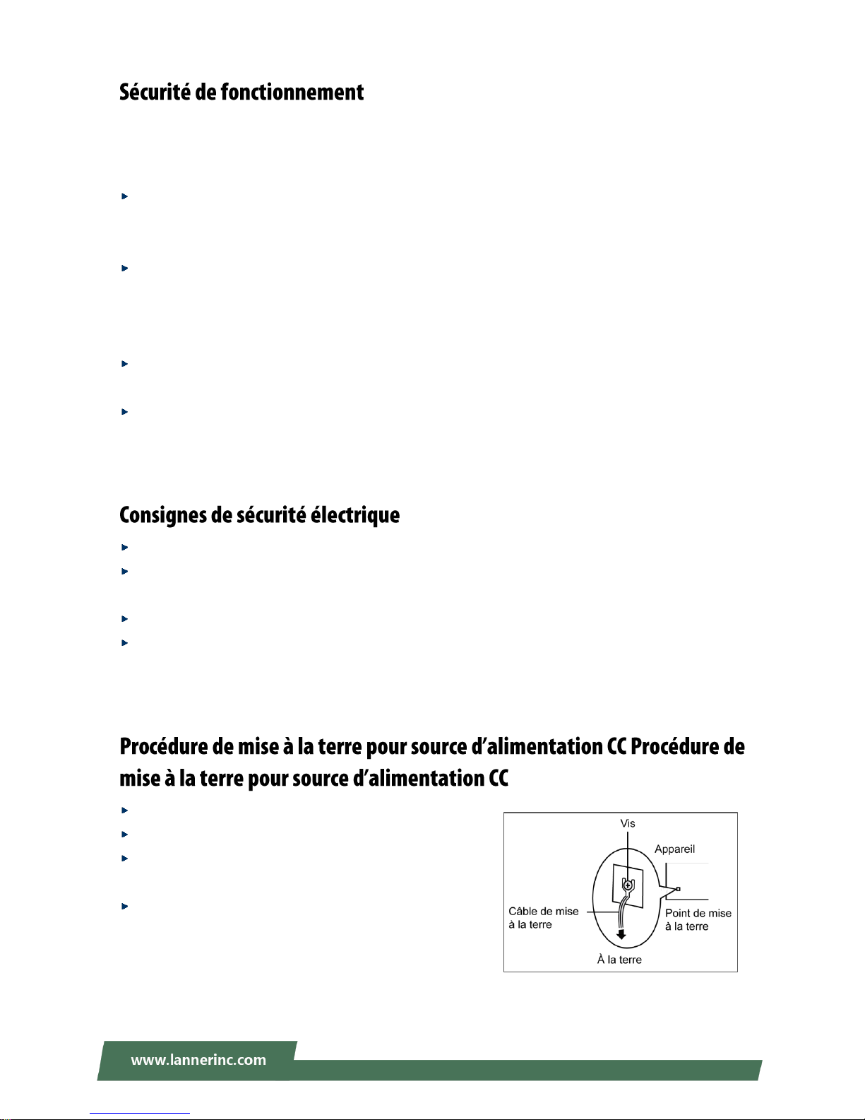
Un câble de mise à la terre est requis et la zone reliant les sections du conducteur doit faire plus de 4
mm2 ou 10 AWG.
Desserrez la vis du terminal de mise à la terre.
Branchez le câble de mise à la terre à la terre.
L’appareil de protection pour la source d’alimentation CC
doit fournir 30 A de courant.
Cet appareil de protection doit être branché à la source
d’alimentation avant l’alimentation CC.
Page 7

NCA-1611 User Manual
7
Version
Date
Descriptions
1.0
2018/02/13
1st Official Release
Page 8
Chapter 1: Product Overview
8
Package Content ......................................................................................................................... 10
Ordering Information ................................................................................................................. 11
Optional Accessories .................................................................................................................. 11
System Specifications ................................................................................................................. 12
Front Panel ................................................................................................................................. 13
Rear Panel ................................................................................................................................... 15
Block Diagram ............................................................................................................................. 16
Motherboard Layout .................................................................................................................. 19
Internal Jumpers & Connectors .................................................................................................. 20
Opening the Chassis ................................................................................................................... 27
Installing the Wireless Module ................................................................................................... 28
Installing the Disk Drive .............................................................................................................. 31
Installing the TPM Module ......................................................................................................... 33
Installing the System Memory .................................................................................................... 34
Connecting the USB Cable & VGA Cable to Mainboard ............................................................. 35
Mounting the System ................................................................................................................. 36
Enter BIOS Setup ........................................................................................................................ 39
Main Setup ................................................................................................................................. 40
Advanced Setup .......................................................................................................................... 41
Page 9
NCA-1611 User Manual
9
IntelRCSetup ............................................................................................................................... 57
Security ....................................................................................................................................... 77
Boot Menu .................................................................................................................................. 80
Save and Exit Menu .................................................................................................................... 81
Warranty Policy .......................................................................................................................... 86
RMA Service ................................................................................................................................ 86
RMA Service Request Form ........................................................................................................ 87
Page 10
Chapter 1: Product Overview
10
The NCA-1611 is a NEBS-compliant desktop network appliance built with Intel® Xeon® D-1500 Series CPU
(codenamed Broadwell-DE NS). It is virtualization-ready, features 8x LAN ports, 2x 10G SFP+, up to 128GB
(RDIMM) system memory, and is optimized with SR-IOV, allowing a device, such as a network adapter, to
separate access to its resources among various PCIe Virtual Functions.
In addition to being NEBS-compliant, the NCA-1611 is also K.21 compliant. Its carrier-grade design comes
with Intel® QuickAssist Technology at 40G, ideal for SD-VPN and SD-Security deployment scenarios. For
wireless connectivity, the NCA-1611 offers dual mini-PCIe (one with SIM reader) supporting Wi-Fi and LTE,
as well as IPMI, altogether simplifying service deployment at remote sites and most SME office branches.
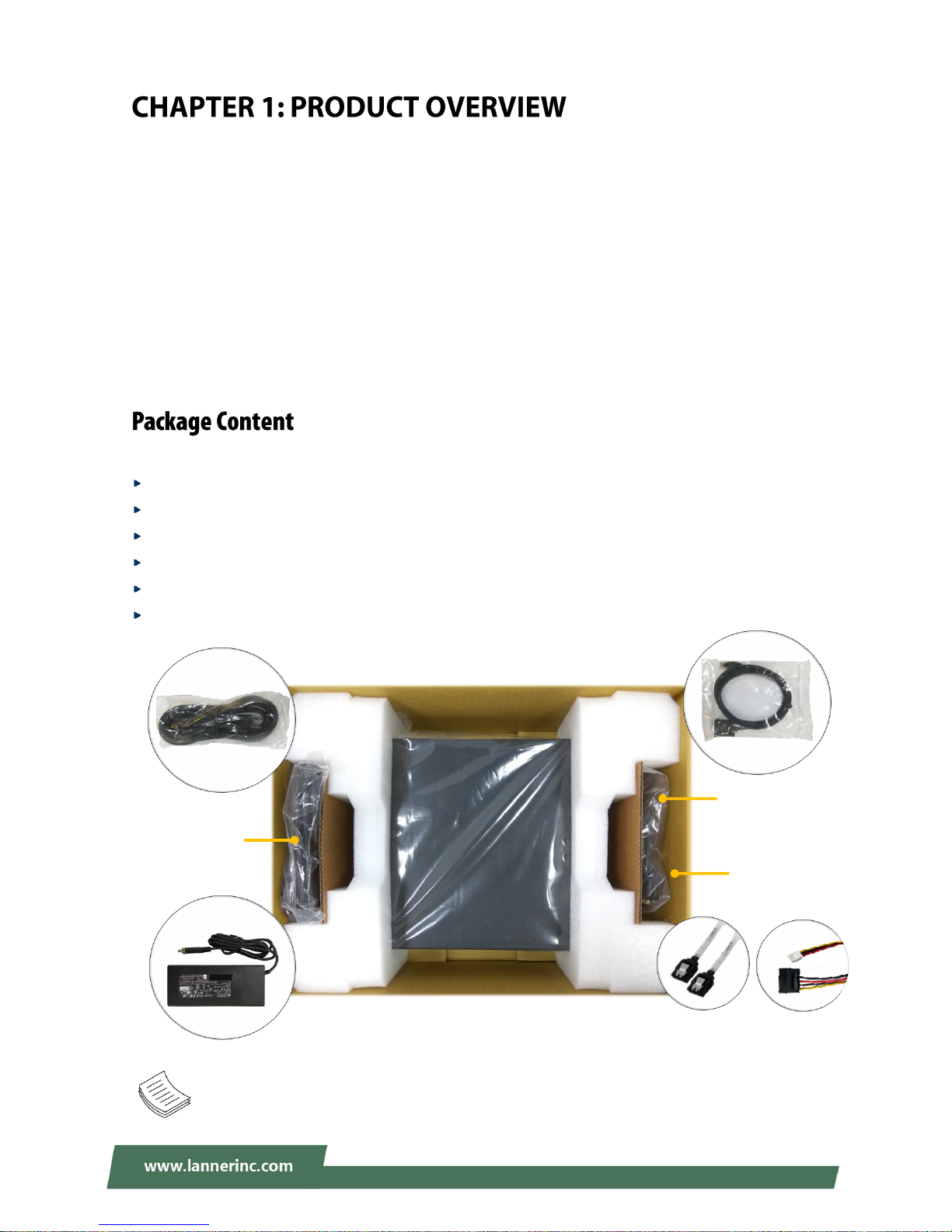
Your package contains the following items:
1x NCA-1611 Network Appliance
1x 90W Power Adapter
1x Power Cable (the provided plug type will vary by region)
1x Console Cable
1x SATA Cable
1x SATA Power Cable
Note: If any component is missing or damaged, please contact your dealer immediately for
assistance.
NCA-1611
Console
Cable
SATA Cable
&
SATA Power Cable
Power
Cable
&
Power
Adapter
Page 11
NCA-1611 User Manual
11
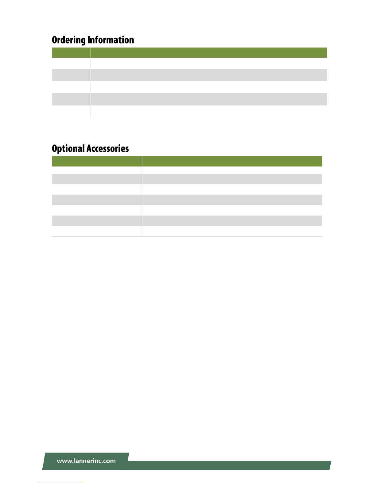
SKU No.
Specification
NCA-1611A
D1543 8C, 6 x GbE RJ45 + 2x SFP + 2x 10G SFP+ w/BMC
NCA-1611B
D1543 8C, 6 x GbE RJ45 + 2x SFP + 2x 10G SFP+
NCA-1611C
D1533 6C, 6 x GbE RJ45 + 2x SFP + 2x 10G SFP+ w/BMC
NCA-1611D
D1513 4C, 6 x GbE RJ45 + 2x SFP + 2x 10G SFP+
NCA-1611E
D1513 4C, 6 x GbE RJ45 + 2x SFP
Model No.
Description
Power Adapter
90W, 12V 7.5A, C14 W/Lock, 150cm, 180°∘
VGA Cable
VGA (DB15) to 12-pin flat cable, 2.0mm Pitch, 30cm
USB Cable (for Main board)
USB (Type A) to 5-pin flat cable, 2.54mm Pitch, 18cm
RJ45 Cable
A standard Category 5E cable supporting UTP, gray, 180cm
Rackmount kit with PSU Bracket
A set of Rackmount kit along with PSU Bracket
Wall-mount kit
A set of Wallmount kit
Wi-Fi/LTE module w/ Antenna
Wi-Fi/LTE module card with Antenna and cable
Page 12
Chapter 1: Product Overview
12
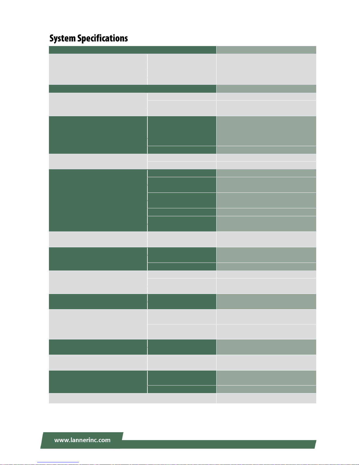
Form Factor
Desktop
Platform
Processor Options
Intel® Xeon® D-1500 (Broadwell-DE NS)
CPU Socket
Onboard
Chipset
SoC
Security Acceleration
Intel® QuickAssist Technology
BIOS
AMI SPI Flash BIOS
System Memory
Technology
DDR4 2133MHz ECC/Non-ECC/RDIMM
Max. Capacity
128GB
Socket
4 x 288pin DIMM
Networking
Ethernet Ports
6 x GbE RJ45 Intel® i350-AM4
2x SFP Intel® i350-AM4 (By SKU)
2x SFP+ SoC integrated MAC (By SKU)
Bypass
1 pair Gen3 (By SKU)
NIC Module Slot
N/A
LOM
IO Interface
1x GbE RJ45 (By SKU)
OPMA slot
IPMI on board (By SKU)
I/O Interface
Reset Button
1
LED
Power/Status/Storage
Power Button
1
Console
1 x RJ45
USB
2 x USB 3.0
LCD Module
N/A
Display
N/A
Power input
2 x DC Jack
Storage
HDD/SSD Support
1 x 2.5” Bay (Optional)
Onboard Slots
1 x SATADOM (Optional)
Expansion
PCIe
N/A
mini-PCIe
2x Mini-PCIe Half Size (PCIe/USB2.0)
SIM card slot
1x Nano-SIM
Miscellaneous
Watchdog
YES
Internal RTC with Li Battery
YES
TPM
YES (Optional)
Cooling
Processor
Passive CPU heatsink
System
3 x cooling fan
Environmental Parameters
Temperature
0 to 50ºC Operating
-20 to 70ºC Non-Operating
Humidity (RH)
5 to 90% Operating
5 to 95% Non-Operating
System Dimensions
(WxDxH)
275 x 44 x 310 mm
Weight
3 kg
Package Dimensions
(WxDxH)
478 x 359 x 163mm
Weight
5kg
Power
Type/Watts
90W power adapter (Optional 1+1)
DC: 12V/7.5A, 90W Max.
Input
AC: 100-240V~, 50-60 Hz
Approvals and Compliance
RoHS, CE/FCC Class A, UL
Page 13
NCA-1611 User Manual
13
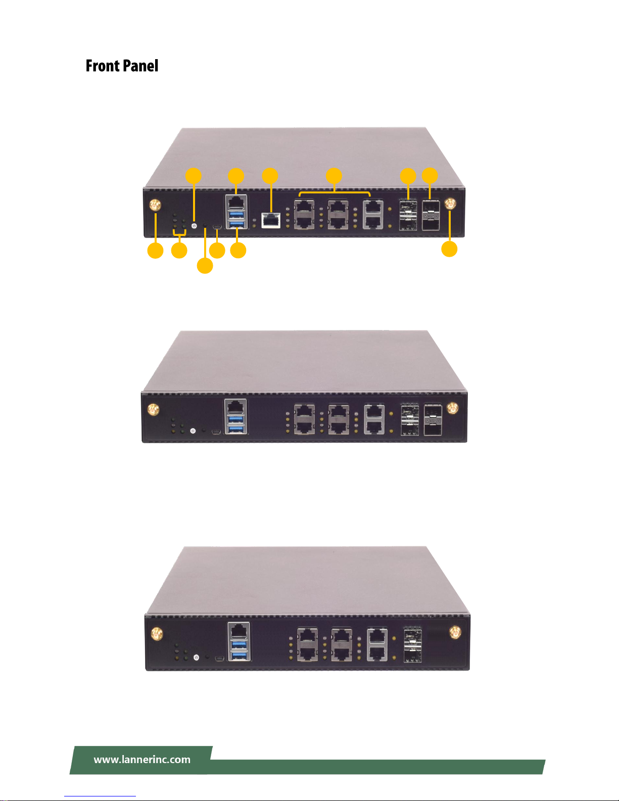
NCA-1611A
NCA-1611C
NCA-1611E
NCA-1611B
NCA-1611D
G I H J E B A D K
K
C
F
Page 14

Chapter 1: Product Overview
14
No.
Description
A
LED Indicators
(System)
Please refer to Appendix A: LED Indicator Explanations for the description
of the LED Indicators.
B
Power Button
Push to power on this device.
C
Reset Button
Software reset
D
Mini USB Port
1x Console Port (Priority)
E
RJ45 Console Port
1x RJ-45 Console Port
F
USB Port
2x USB 3.0 ports
G
IPMI Port
1x Serial/Ethernet management port (By SKU)
H
GbE Port
6x GbE RJ45
I
SFP Port
2x SFP ports
J
SFP+ Port
2x SFP+ ports (By SKU)
K
Front Antenna Port
2x SMA connector for Aux connector of Wi-Fi and LTE module
System Power
System Status
HDD Activity
WWAN/WLAN Connection Status
WLAN Connection Status
Page 15

NCA-1611 User Manual
15
No.
Description
L
Grounding Point
For safety measures to help prevent people from accidentally
coming in contact with electrical hazards
M
ESD Protection Screw
Hole
For safety measures to help prevent people from accidentally
coming in contact with electrical hazards
N
Fan
3x Quiet Fan
O
Power Supply
2x 12V DC in
P
Rear Antenna Port
2x SMA connector for the Main connector of Wi-Fi and LTE module
N O P P L
M
Page 16
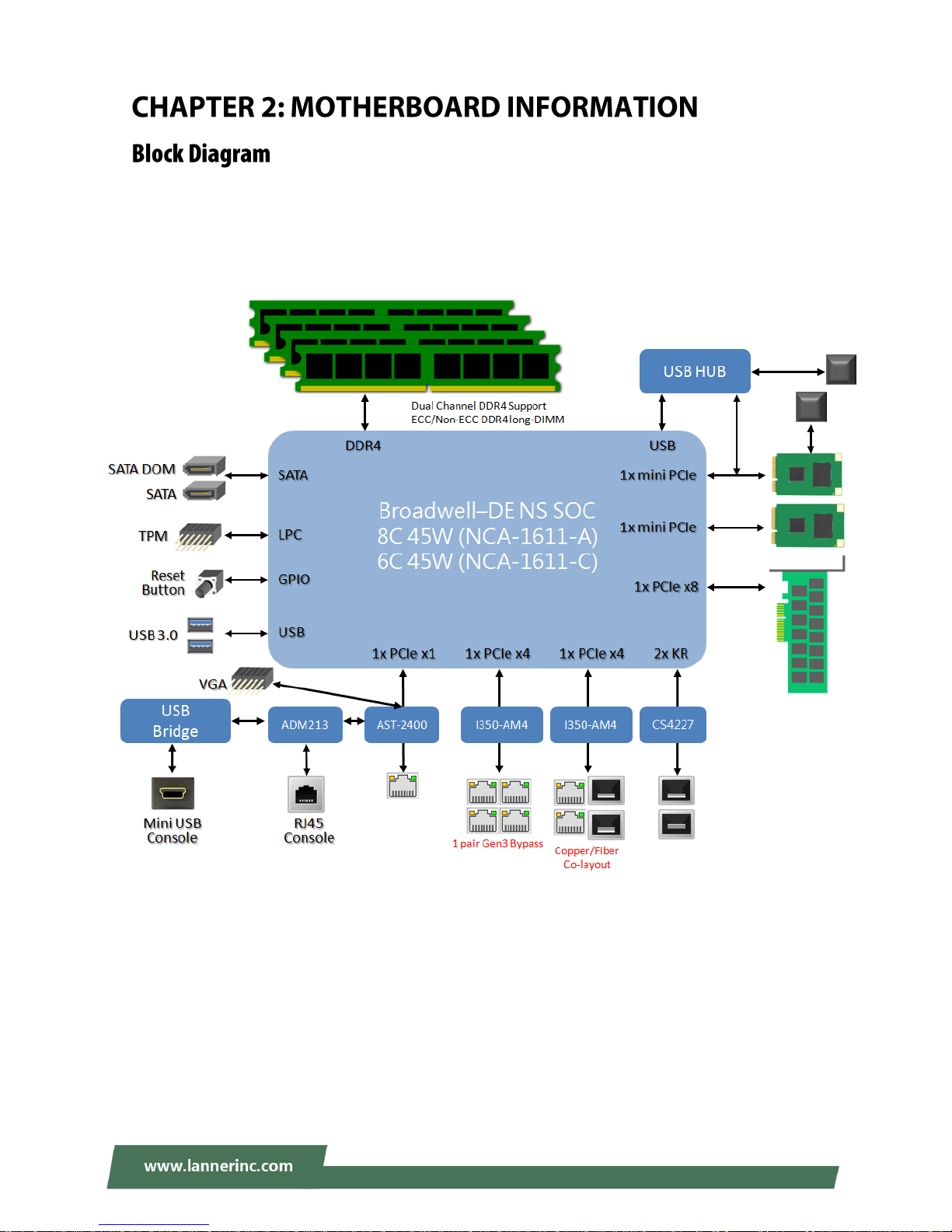
Chapter 2: Motherboard Information
16
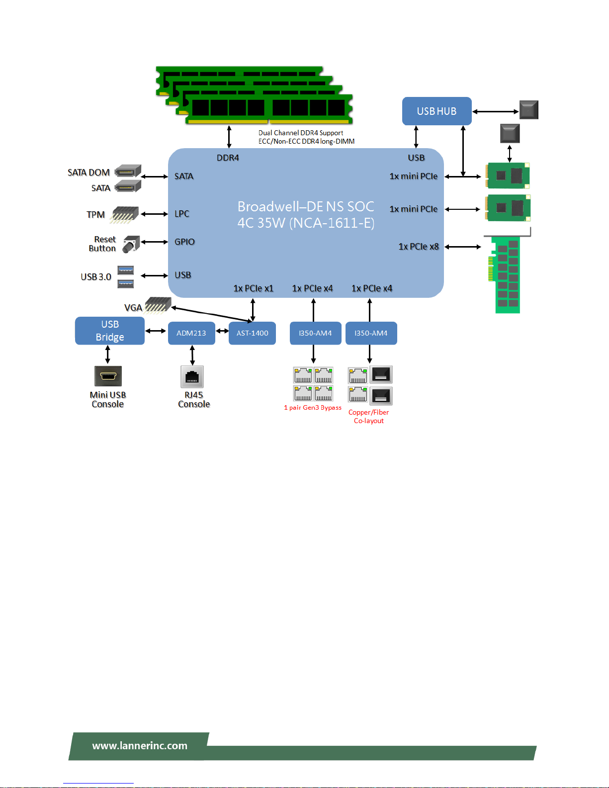
The block diagram indicates how data flows among components on the motherboard. Please refer to the
following figure for your motherboard’s layout design.
NCA-1611A
NCA-1611C
Page 17
NCA-1611 User Manual
17
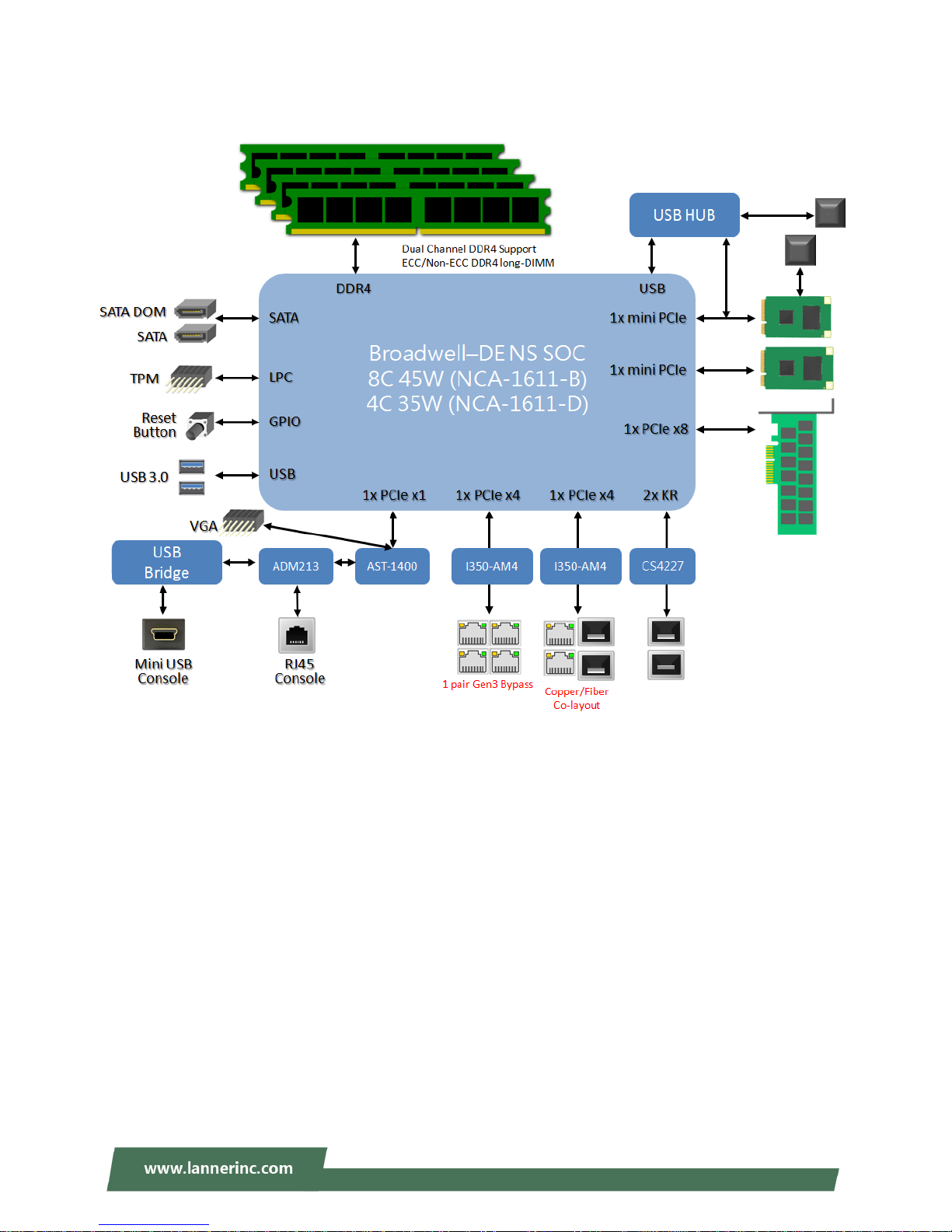
NCA-1611B
NCA-1611D
Page 18
Chapter 2: Motherboard Information
18
NCA-1611E
Page 19
NCA-1611 User Manual
19
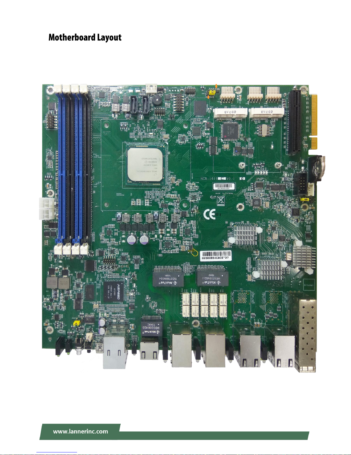
The motherboard layout shows the connectors and jumpers on the board. Refer to the following picture as
a reference of the pin assignments and the internal connectors.
JSATA1
JCMOS1
JTPM1
J20
MPCIE1
JCPLD1
SIM1
SATAPWR2
FAN1 FAN2 FAN3
ATX3
ATX4
J80PORT1
J16
SW3
JSATA2
SW2
CONN2
JRESET1
JSPIROM1
JGPI
MPCIE2
JCOM3
JVGA1
Page 20
Chapter 2: Motherboard Information
20
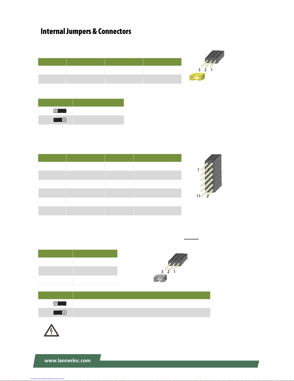
JCOMS1: Clear CMOS pin header
Use the jumper setting to clear CMOS
JTPM1: TPM module pin header
Supports a Trusted Platform Module (TPM) system
J20: SATADOM/SATA pin header
User jumper setting to switch between the two supported disk types on JSATA1: SATA HDD/SSD or
SATADOM.
Warning: By adjusting the jumper to SATADOM mode, please make sure you connect a
SATADOM to JSATA1; attaching a SATA cable to JSATA1 under SATADOM mode will result in
short circuit.
Pin
Description
Pin
Description
1
VCC_RTC
2
PCH_RTCRST#
3
GND
Setting
Mode
1-2
Normal (Default)
2-3
Clear CMOS
Pin
Description
Pin
Description
1
LPC_SERIRQ
2
LPC_FRAME#
3
LPC_LAD0
4
CLK_33M_PORT80
5
LPC_LAD1
6
P3V3_SB
7
LPC_LAD2 8 NC
9
LPC_LAD3
10
P3V3
11
PLT_RST#
12
GND
Pin
Description
1
GND
2
PWR_SATA_DOM
3
P5V
Setting
Mode
1-2
For JSATA1 to connect with a SATA HDD/SSD (Default Setting)
2-3
For JSATA1 to connect with a SATADOM
Page 21
NCA-1611 User Manual
21
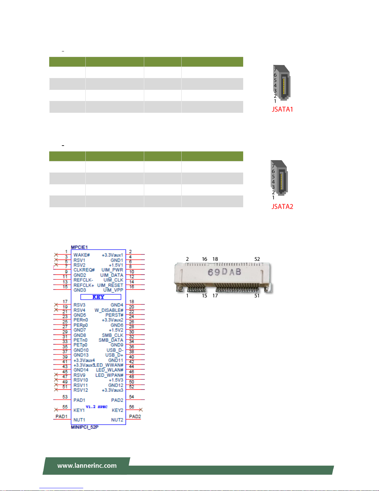
JSATA1
180° SATA Connector
JSATA2
180° SATA Connector
MPCIE1: Mini-PCIe connector
Supports both 3G/4G and USB/PCIe interface adapter
Pin
Description
Pin
Description
1
GND
2
SATA_CTX_C_DRX_P
3
SATA_CTX_C_DRX_N
4
GND
5
SATA_DTX_CRX_N
6
SATA_DTX_CRX_P
7
PWR_SATA_DOM
Pin
Description
Pin
Description
1
GND
2
SATA_CTX_C_DRX_P
3
SATA_CTX_C_DRX_N
4
GND
5
SATA_DTX_CRX_N
6
SATA_DTX_CRX_P
7
GND
Page 22
Chapter 2: Motherboard Information
22
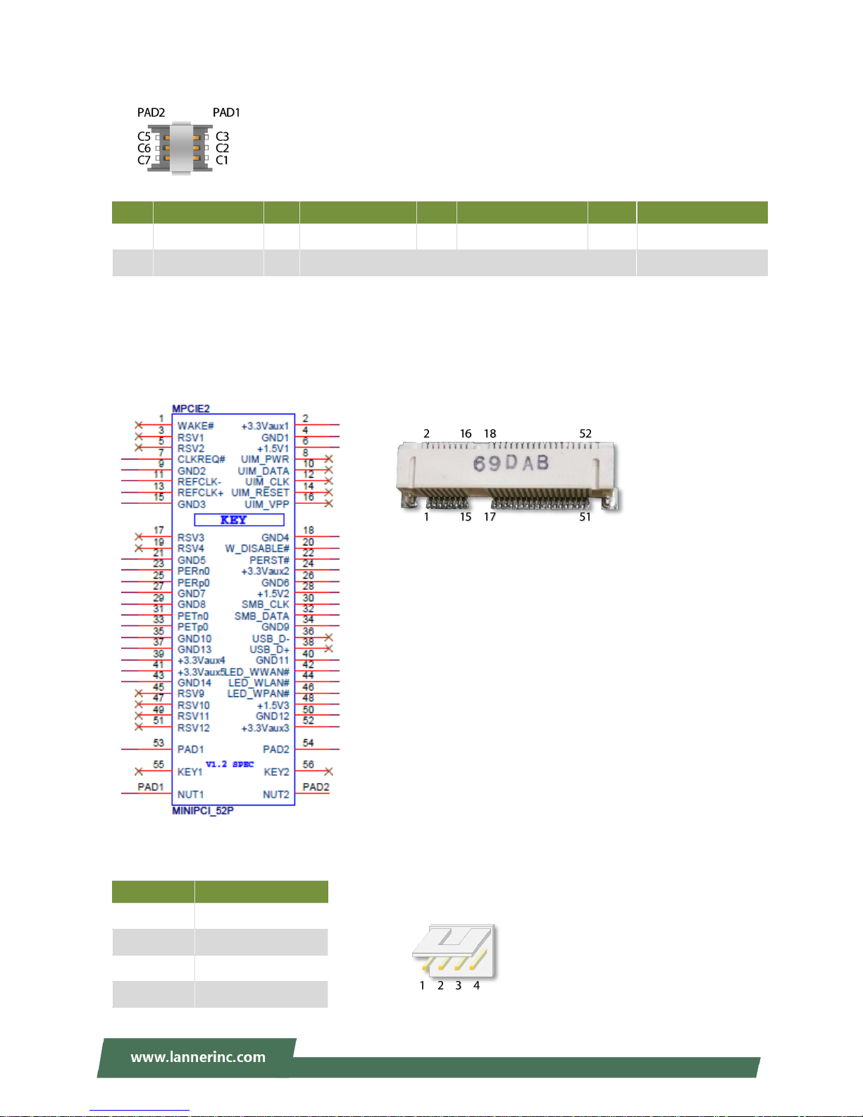
SIM Card Connector
MPCIE2: Mini-PCIe connector
Supports Wi-Fi PCIe interface adapter
SATAPWR2: SATA Power Connector
Pin
Description
Pin
Description
Pin
Description
Pin
Description
C1
VCC
C2
RST
C3
CLK
PAD1
PAD1
C5
GND
C6
VPP
C7
DATA
PAD2
PAD2
Pin
Description
1
P12V
2
GND
3
GND
4
P5V
Page 23
NCA-1611 User Manual
23
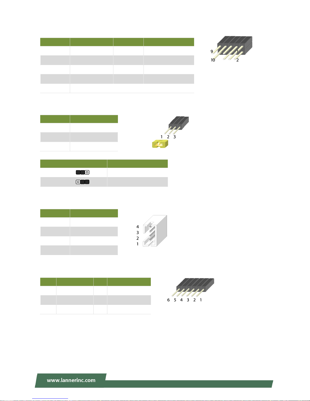
J80PORT1:80 Debug port pin header
J16: Bypass flash jump setting pin header
JCOM3: Bypass flash connector
JCPLD1: CPLD Flash pin header
Pin
Description
Pin
Description
1
CLK_33M_PORT80
2
LPC_LAD1_R
3
80PORT_RST#
4
LPC_LAD0_R
5
LPC_FRAME#_P80
6
P3V3
7
LPC_LAD3_P80
9
LPC_LAD2_P80
10
GND
Pin
Description
1
P3V3_SB
2
CPLD_LED3
3
GND
ARM Programming Selection
Mode
0(1-2)
Enabled (Default)
1(2-3)
Disabled (default)
Pin
Description
1
P3V3_SB
2
NXP_RXD
3
GND
4
NXP_TXD
Pin
Description
Pin
Description
1
P3V3_SB
2
CPLD_TDO
3
CPLD_TD
4
CPLD_TMS
5
GND
6
CPLD_TCK
Page 24
Chapter 2: Motherboard Information
24
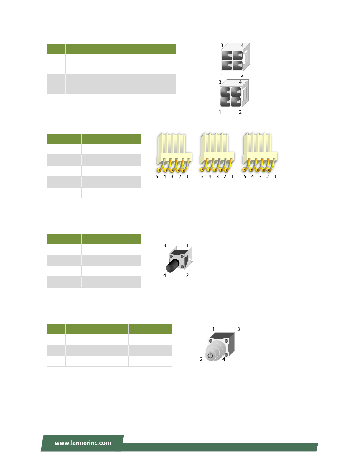
ATX3/ATX4: ATX Power connector 4P
FAN3/FAN2/FAN1: CPU Fan
SW2: Reset button
SW5: Power button
Pin
Description
Pin
Description
1
GND
2
V12A_DC_A/
V12A_DC_B
3
GND
4
V12A_DC_A/
V12A_DC_B
Pin
Description
1
CPUFANOUT
2
NC
3
BMC_FAN_TACH0/1/2
4
P12V
5
GND
Pin
Description
1
GND
2
GND
3
GND
4
FP_RST_SEL
Pin
Description
Pin
Description
1
GND
2
GND
3
PWRON#
4
PWRON#
L1
SUSLED
L2
SPRLED-
Page 25
NCA-1611 User Manual
25
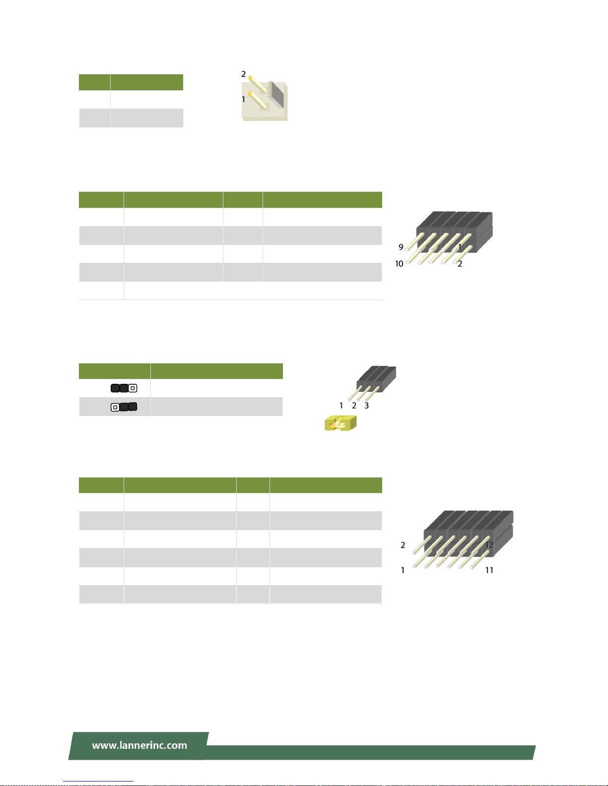
CONN2: Power pin header
JSPIROM1: SPI ROM flash pin header
JRESET1: JRESET pin header for mode selection of Reset button on Front Panel
JVGA1: VGA pin header
Pin
Description
1
GND
2
PWRON#
Pin
Description
Pin
Description
1
NC 2 NC
3
SPI1_CS0#_DUAL
4
P3V3_SB_SPI
5
SPI_MISO_DUAL
6
SPI_HOLD0_L
7
NC
8
SPI_CLK_DUAL
9
GND
10
SPI_MOSI_DUAL
Setting
Mode
1-2
Hardware Reset
2-3
Software Reset (Default)
Pin
Description
Pin
Description
1
DAC_RO
2
GND
3
DAC_GO
4
GND
5
DAC_BO
6
GND
7
HSYNC_O
8
NC
9
VSYNC_O
10
GND
11
DDC_DATA
12
DDC_CLK
Page 26

Chapter 2: Motherboard Information
26
JGP1: GPIO pin Header
Pin
Description
Pin
Description
1 R 2
GND
3 G 4
GND
5 B 6
GND
7
H-SYNC
8
GND
9
V-SYNC
10
GND
Page 27
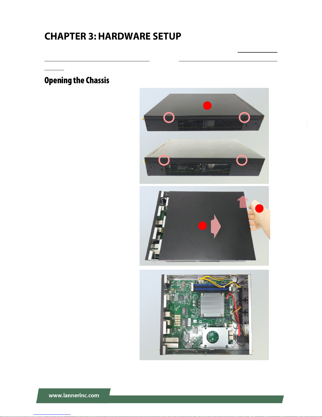
NCA-1611 User Manual
27
To reduce the risk of personal injury, electric shock, or damage to the unit, please remove all power
connections to completely shut down the device. Also, please wear ESD protection gloves when conducting
the steps in this chapter.
1. On both sides of the system, loosen
the 2 screws as shown in the
photos.
2. Gently pull the cover backward a
bit.
3. Lift the cover up to remove it.
2
3
Front
Rear
1
Page 28

Chapter 3: Hardware Setup
28
The motherboard provides two mini-PCIe slots, with one supporting 3G/4G data transmission module and
the other one supporting Wi-Fi module.
1. Locate MPCIE1 slot.
2. Align the notch of the DIMM module
with the socket key in the slot.
3. Insert the module at 30 degrees into
the socket until it is fully seated in the
connector.
Notch
Socket
Key
2 3 1
Page 29

NCA-1611 User Manual
29
4. Push down on the module and secure
it with screws that come with it.
5. Snap the end of the antenna cable
onto the connector on the module.
Press down the golden end of the
cable until it clicks into place.
6. After you replace the system’s cover,
attach the antenna to the
corresponding connector on the panel.
4
6
Page 30

Chapter 3: Hardware Setup
30
1. Locate MPCIE2 slot.
2. Insert the Nano-SIM card. Make sure
the card’s gold contacts face
downwards and the angled corner of
the card is positioned correctly as
shown in the picture.
3. Follow the procedures for installing a
Wi-Fi supported module in the
previous section to install your 3G/4G
supported module.
1 3 2
Page 31

NCA-1611 User Manual
31
NCA-1611 is built with one 2.5” HDD/SSD slot drive bay as well as the support for SATADOM. The following
will discuss disk drive installation procedures based on their designs.
1. Locate the 2.5” disk bay area in the
chassis.
2. Loosen the screws that secure the
empty HDD tray.
3. Insert the four rubber washers into
the four notches of the tray.
4. Install the disk into the tray and
secure it with the provided disk
screws. Make sure the SATA
connector faces outwards as shown
in the picture.
SATA
Contacts
Align and push the
washer horizontally
into the notch.
3
4
2
Page 32

Chapter 3: Hardware Setup
32
5. Insert one end of the SATA data
cable to the SATA contacts on the
disk. Do the same to the SATA power
cable. Make the two cables’ ends go
under and pass through the CPU
dusk cover
6. Secure the tray on the motherboard
with four provided screws.
7. Insert the other end of the SATA data
cable to the SATA2 port on the
motherboard, and the end of the
SATA power cable to the SATA Power
port. Arrange the cables and route
them neatly to avoid them from
getting tangled.
To install and enable SATA DOM, please:
1. Adjust the jumper on
SATADOM/SATA pin header to
SATADOM mode following the
instructions in Internal Jumpers &
Connectors.
2. Insert the SATADOM into JSATA1
port.
Warning: By adjusting the jumper to SATADOM mode, please connect only a SATADOM to
JSATA1.
6 5 7
JSATA1
SATAPWR2
JSATA2
Page 33

NCA-1611 User Manual
33
1. Locate JTPM1 pin header.
2. Align the pins on the module with the
corresponding ones on the pin header;
Pin 1 is illustrated as a triangle shape.
3. Insert the module into the pin header
until it is totally seated.
4. Enter BIOS Setup screen to enable this function. Go to Advanced Trusted Computing Security
Device Support select “Enable”
JTPM1
11 1
12 2
2
1
Page 34

Chapter 3: Hardware Setup
34
The motherboard supports DDR4 registered DIMM memory for heavy-duty operations. Please follow the
steps below to install the DIMM memory modules.
1. Locate the DIMM slot.
2. Pull open the DIMM slot latches.
3. Align the notch of the DIMM module
with the socket key in the slot.
4. Push the module on its both corners
into the slot until it is firmly seated.
The latches will automatically snap
locked.
Notch
Socket Key
2 2 3
4
1
Page 35

NCA-1611 User Manual
35
To connect the internal 10-pin header to USB cable or 12-pin header to VGA (DB15) cable to Motherboard,
make sure the pins on the cable’s head matches the corresponding ones on the header.
USBA2
JVGA1
VGA cable
USB cable
Page 36

Chapter 3: Hardware Setup
36
With the Rackmount Kit, NCA-1611 can be fixed onto rack post along with the system’s power adapter(s).
Please contact Lanner‘s sales representative for purchasing this kit.
What’s in the Rackmount Kit
Check the kit contents for the following items:
1x pair of Ear Brackets
1x pair of Adapter Holders
1x pair of Clamps
1x Accessory Pack including long screws for the
fixture of the ear brackets and short screws for
the fixture of the adapter.
Attaching the Rackmount Assembly to the Chassis
1. On one side of the system, align the ear bracket
and the adapter holder to the screw holes on the
side panel and then assemble them using five
long screws.
2. Secure the two standoffs onto the holder.
Adapter Holder
Ear
Bracket
Long Screw
Clamp
Short Screw
1
1
2
Page 37

NCA-1611 User Manual
37
3. Get the power adapter’s connector through the
back of the holder.
4. Attach the power adapter’s connector to
the power supply slot and fasten the screw
lock.
5. Insert the battery into the holder.
6. Secure the adapter with the clamp using two
short screws.
7. Arrange the cables and route them neatly to
avoid them from getting tangled.
8. Depending on your demand, a redundant power
adapter can be installed on the other side of the
system, ensuring continuous operation of the
whole system if the main power supply should
fail.
5 3
4 6 7 8
Page 38

Chapter 3: Hardware Setup
38
Installing the System to the Rack
9. In the rack, install a shelf to support the system.
10. Hold the system with its front facing you, lift and carefully insert the system into the rack.
11. Attach the brackets to the rail rack using screws and appropriate round-hole/square-hole retainer
nuts.
Page 39

NCA-1611 User Manual
39
To enter the BIOS setup utility, simply follow the steps below:
1. Boot up the system.
2. Press <Delete> during the boot-up if you connect a keyboard to this unit. But if you connect a PC to this
unit through console USB/Serial connection, then press <Tab>. Your system should be running POST
(Power-On-Self-Test) upon booting up.
3. Then you will be directed to the BIOS main screen.
4. Instructions of BIOS navigations:
Control Keys
Description
select a setup screen, for instance, [Main], [IntelRCSetup], [Security], [Boot], and
[Save & Exit]
select an item/option on a setup screen
<Enter>
select an item/option or enter a sub-menu
+/-
to adjust values for the selected setup item/option
F1
to display General Help screen
F2
to retrieve previous values, such as the parameters configured the last time you
had entered BIOS.
F3
to load optimized default values
F4
to save configurations and exit BIOS
<Esc>
to exit the current screen
Page 40

Chapter 4: BIOS Setup
40
Setup main page displays a description of BIOS information and project version information. You can also
setup the System Time and System Date here.
(The screenshots presented in section are for reference only)
Item
Description
System Date
Set the Date. Use Tab to switch between Date elements. Default
Ranges: Year: 2005-2099 Months: 1-12
Days: dependent on month.
System Time
Set the Time. Use Tab to switch between Time elements.
Page 41

NCA-1611 User Manual
41
Use [←] / [→] to select [Advanced] setup screen. Under this screen, you may use [↑] [↓] to select an item
you want to configure.
Page 42

Chapter 4: BIOS Setup
42
This option allows you to configure parameters regarding security device. Press “Enter“ to access the
submenu.
Item
Value
Description
Security Device
Support
Enabled
Disabled
Enables or Disables BIOS support for the
security device. O.S. will not show Security
Device. TCG EFI protocol and INT1A interface
will not be available.
Page 43

NCA-1611 User Manual
43
This option allows you to configure parameters about Super IO Chip. Press “Enter“ to access the submenu.
Serial port 1 Configuration
Item
Value
Description
Serial Port
Enabled
Disabled
Enable or Disable Serial Port 1.
Device Settings
NA
IO=3F8h; IRQ = 4
Page 44

Chapter 4: BIOS Setup
44
If with the case’s support, enabling this option will have the unit sound when someone opens the case of
this unit, which is considered against your organization’s policy. The default is “Disabled”.
Item
Value
Description
Case Open
Enabled
Disabled
Enable or Disable Case Open function.
Page 45

NCA-1611 User Manual
45
Item
Value
Description
Control Legacy PXE
Boot from
Disabled
LAN1
LAN2
LAN3
LAN4
LAN5
LAN6
LAN7
LAN8
LAN9
LAN10
Control which LAN the Legacy PXE boots
from.
Page 46

Chapter 4: BIOS Setup
46
Item
Value
Description
Status LED
OFF
GREEN
RED
Configure Status LED.
Page 47

NCA-1611 User Manual
47
This option allows you to configure Digital I/O pin properties. Select the desired pin and press <Enter> to
modify. The default is “Output Low”.
Item
Value
Description
Digital I/O Output 1
Output Low
Output High
Configure Digital I/O Pin1.
Digital I/O Output 3
Output Low
Output High
Configure Digital I/O Pin3.
Digital I/O Output 5
Output Low
Output High
Configure Digital I/O Pin5.
Digital I/O Output 7
Output Low
Output High
Configure Digital I/O Pin7
Page 48

Chapter 4: BIOS Setup
48
This option allows you to configure parameters about serial port console redirection. Press “Enter “to access
the submenu. The default is “Enabled”.
Item
Value
Description
COM0
Console Redirection
Enabled
Disabled
Console Redirection Enable or Disable.
Page 49

NCA-1611 User Manual
49
Console Redirection Settings: select this item to enter the setting sub-menu. These settings specify how
the host computer and the remote computer will exchange data. Both computers should have the same or
compatible settings.
Item
Value
Description
Terminal Type
VT100
VT100+
VT-UTF8
ANSI
ANSI: Extended ASCII char set.
VT100: ASCII char set.
VT100+: Extends VT100 to support color,
function keys, etc.
VT-UTF8: Uses UTF8 encoding to map
Unicode chars onto 1 or more bytes.
Bits per second
9600
19200
38400
57600
115200
Selects serial port transmission speed. The
speed must be matched on the other side.
Long or noisy lines may require lower speeds.
Data Bits
7
8
Data Bits
Parity
None
Even
Odd
A parity bit can be sent with the data bits to
detect some transmission errors.
Page 50

Chapter 4: BIOS Setup
50
Mark
Space
Stop Bits
1
2
Stop bits indicate the end of a serial data
packet.
Flow Control
None
Hardware RTS/CTS
Flow control can prevent data loss from
buffer overflow.
VT-UTF8 Combo Key
Support
Disabled
Enabled
Enable VT-UTF8 Combination Key Support for
ANSI/VT100 terminals
Recorder Mode
Disabled
Enabled
With this mode enabled only text will be sent.
This is to capture Terminal data.
Resolution 100x31
Disabled
Enabled
Enables or disables extended terminal
resolution.
Putty KeyPad
VT100
LINUX
XTERM86
SCO
ESCN
VT400
Select FunctionKey and KeyPad on Putty.
Page 51

NCA-1611 User Manual
51
Legacy Console Redirection Setting
Item
Value
Description
Redirection COM Port
COM0
COM1
Select a COM port to display redirection of
Legacy OS and Legacy OPROM Messages
Resolution
80x24
80x25
On Legacy OS, the Number of Rows and
Columns supported redirection
Redirect After POST
Always Enable
BootLoader
When Bootloader is selected, then Legacy
Console Redirection is disabled before
booting to legacy OS. When Always Enable is
selected, then Legacy Console Redirection is
enabled for legacy OS. The default setting for
this option is set to Always Enable.
Page 52

Chapter 4: BIOS Setup
52
This option allows you to configure parameters to be programmed into PCI Latency Timer Register.
Item
Value
Description
SR-IOV Support
Disabled
Enabled
If the system has SR-IOV capable PCIe
Devices, this option Enables or Disables
Single Root IO Virtualization Support.
Page 53

NCA-1611 User Manual
53
This option allows you to enable or disable ROM execution settings.
Item
Value
Description
CSM Support
Disabled
Enabled
Enable/Disable CSM Support
Network
Do Not Launch
UEFI
Legacy
Controls the execution of UEFI and Legacy
PXE OpROM
Storage
Do Not Launch
UEFI
Legacy
Controls the execution of UEFI and Legacy
Storage OpROM
Video
Do Not Launch
UEFI
Legacy
Controls the execution of UEFI and Legacy
Video OpROM
Other PCI device
Do Not Launch
UEFI
Legacy
Determines OpROM execution policy for
devices other than Network, Storage, or
Video
Page 54

Chapter 4: BIOS Setup
54
This option allows you to change USB configuration parameters.
Legacy USB Support:
Item
Value
Description
Legacy USB Support
Enabled
Disabled
Auto
Enables Legacy USB support.
AUTO option disables legacy support if
no USB devices are connected.
DISABLE option will keep USB devices
available only for EFI applications.
XHCI Hand-off
Enabled
Disabled
This is a workaround for OSes without
XHCI hand-off support. The XHCI
ownership change should be claimed by
XHCI driver.
EHCI Hand-off
Enabled
Disabled
This is a workaround for OSes without
EHCI hand-off support. The EHCI
ownership change should be claimed by
EHCI driver.
USB Mass Storage
Driver Support
Enabled
Disabled
Enable/Disable USB Mass Storage Driver
Support.
Page 55

NCA-1611 User Manual
55
USB transfer time-out
1 sec
5 sec
10 sec
20 sec
The time-out value for Control, Bulk, and
Interrupt transfers.
Device reset
time-out
1 sec
5 sec
10 sec
20 sec
USB mass storage device Start Unit
command time-out.
Device power-up
delay
Auto
Manual
Maximum time the device will take
before it properly reports itself to the
Host Controller. 'Auto' uses default
value: for a Root port, it is 100 ms, for a
Hub port the delay is taken from Hub
descriptor.
Page 56

Chapter 4: BIOS Setup
56
Item
Value
Description
Network Stack
Disabled
Enabled
Enable/Disable UEFI Network Stack
Page 57

NCA-1611 User Manual
57
Use [←] / [→] to select the Chipset menu item from the BIOS setup screen to enter the IntelRCSetup Setup
screen. Users can select any of the items in the left frame of the screen.
Item
Value
Description
Processor
Configuration
None
Displays and provides option to change
the Processor Settings
Advanced Power
Management
Configuration
None
Displays and provides option to change
the Power Management Settings
QPI Configuration
None
Displays and provides option to change
the QPI Settings
Memory
Configuration
None
Displays and provides option to change
the Memory Settings
IIO Configuration
None
Displays and provides option to change
the IIO Settings
PCH Configuration
None
Displays and provides option to change
the PCH Settings
Server ME
Configuration
None
Configure Server ME Technology
Parameters
Page 58

Chapter 4: BIOS Setup
58
Item
Value
Description
Hyper-Threading
[ALL]
Disabled
Enabled
Enables Hyper Threading (Software
Method to Enable/Disable Logical
Processor threads.
Execute Disable Bit
Disabled
Enabled
When disabled, forces the XD feature
flag to always return 0.
VMX
Disabled
Enabled
Enables the Vanderpool Technology,
takes effect after a reboot.
AES-NI
Disabled
Enabled
Enable/disable AES-NI support
Hyper-Threading
[ALL]
Disabled
Enabled
Enables Hyper Threading (Software
Method to Enable/Disable Logical
Processor threads.
Page 59

NCA-1611 User Manual
59
Item
Value
Description
EIST (P-states)
Disabled
Enabled
When enabled, OS sets CPU frequency
according load. When disabled, CPU
frequency is set at max non-turbo.
CPU P State Control
None
Controls CPU frequency.
CPU C State Control
None
Control CPU idle states
CPU Advanced PM
Turning
None
Additional CPU Power Management
settings.
DRAM RAPL
Configuration
None
DRAM RAPL Control Sub Menu
Page 60

Chapter 4: BIOS Setup
60
CPU C State Control
Item
Value
Description
CPU C State
Disabled
Enabled
Enables the Enhanced Cx state of the
CPU, takes effect after a reboot.
CPU C6 report
Disabled
Enabled
Enable/Disable CPU C6 (ACPI C2) report
to OS Recommended to be enabled.
Enhanced Halt State
(C1E)
Disabled
Enabled
Enables the Enhanced C1E state of the
CPU, takes effect after a reboot.
Page 61

NCA-1611 User Manual
61
Energy Perf BIAS
Item
Value
Description
Energy Performance
Tuning
Disabled
Enabled
Selects whether BIOS or Operating System
chooses energy performance bias tuning.
Energy Performance
BIAS setting.
Performance
Balanced Performance
Balanced Power
Power
Set Energy Performance BIAS, which overrides
OS setting.
Power/Performance
Switch
Disabled
Enabled
MSR 1FCh Bit[24] =
PWR_PERF_TUNING_ENABLE_DYN_SWITCHING
Page 62

Chapter 4: BIOS Setup
62
DRAM RARL Configuration
Item
Value
Description
DRAM RAPL Baseline
Disabled
DRAM RAPL Mode 0
DRAM RAPL Mode 1
DRAM RAPL Baseline enabled and
baseline mode
Page 63

NCA-1611 User Manual
63
Item
Value
Description
Link L0s Enable
Disable
Enable
Link L0s Enable:Disable,Enable,Auto(default)
COD Enable
Disable
Enable
Auto
Enable/disable Cluster on Die.
Early Snoop
Disable
Enable
Auto
Page 64

Chapter 4: BIOS Setup
64
Item
Value
Description
Enforce POR
Auto
Enforce POR
Disabled
Enforce Stretch Goals
Enable to enforce POR restrictions for DDR3
frequency and voltage programming
Memory Frequency
1333
1400
1600
1800
1867
2000
2133
Maximum Memory Frequency Selections in
Mhz. Do not select Reserved
Memory Thermal
None
Set memory thermal settings
Memory Map
None
Set memory mapping settings
Page 65

NCA-1611 User Manual
65
Memory Thermal
Item
Value
Description
Memory Power
Savings Mode
Auto
Disabled
APD On
User Defined
Configures CKE and related Memory Power
Savings Features
Page 66

Chapter 4: BIOS Setup
66
Memory Map
Item
Value
Description
A7 Mode
Disable
Enable
A7 Mode Disable/Enable
Page 67

NCA-1611 User Manual
67
Item
Value
Description
IIO0 Configuration
None
Intel VT for Directed
I/O (VT-d)
None
Press <Enter> to bring up the Intel VT for
Directed I/O (VT-d) Configuration menu.
PCI-E ASPM Support
(Global)
Disable
L1 Only
This option enables/disables the ASPM support
for all downstream devices.
Page 68

Chapter 4: BIOS Setup
68
IIO0 Configuration
Page 69

NCA-1611 User Manual
69
Intel VT for Directed I/O (VT-d)
Item
Value
Description
Intel VT for Directed
I/O (VT-d)
Disable
Enable
Enable/Disable Intel Virtualization Technology for
Directed I/O (VT-d) by reporting the I/O device
assignment to VMM through DMAR ACPI Tables.
Page 70

Chapter 4: BIOS Setup
70
Item
Value
Description
PCI Express
Configuration
None
PCI Express Configuration settings
PCH SATA
Configuration
None
SATA devices and settings
USB Configuration
None
USB Configuration Settings
Security
Configuration
None
Security Configuration
Restore AC Power
Loss
Power On
Power Off
Last State
Select S0/S5 for ACPI state after a G3
Page 71

NCA-1611 User Manual
71
PCI Express Configuration
Item
Value
Description
PCI-E ASPM Support
(Global)
Disable
L1 Only
This option enables/disables the ASPM
support for all downstream devices.
PCIe Root Port Function
Swapping
Disabled
Enabled
Enable PCIe root port function swapping
feature to dynamically assign function 0
to the enabled root port.
PCI Express Root Port 2
None
PCI Express Root Port 2 Settings
PCI Express Root Port 3
None
PCI Express Root Port 3 Settings
Page 72

Chapter 4: BIOS Setup
72
PCI Express Root Port
Item
Value
Description
PCI-E ASPM Support
(Global)
Disable
L1 Only
This option enables/disables the ASPM
support for all downstream devices.
PCIe Root Port Function
Swapping
Disabled
Enabled
Enable PCIe root port function swapping
feature to dynamically assign function 0
to the enabled root port.
PCI Express Root Port 2
None
PCI Express Root Port 2 Settings
PCI Express Root Port 3
None
PCI Express Root Port 3 Settings
Page 73

NCA-1611 User Manual
73
PCH SATA Configuration
Item
Value
Description
SATA Controller
Disabled
Enabled
Enable or Disable SATA Controller
Configure SATA as
IDE
AHCI
This will configure SATA as IDE, RAID or
AHCI.
Port 1
Disabled
Enabled
Enable or Disable SATA Controller
Spin Up Device
Disabled
Enabled
PCI Express Root Port 3 Settings
SATA Device Type
Hard Disk Drive
Solid State Drive
Identify the SATA port is connected to
Solid State Drive or Hard Disk Drive
Page 74

Chapter 4: BIOS Setup
74
USB Configuration
Item
Value
Description
xHCI Mode
Smart Auto
Auto
Enabled
Disabled
Manual
Mode of operation of xHCI controller.
Page 75

NCA-1611 User Manual
75
Security Configuration
Item
Value
Description
GPIO Lockdown
Disabled
Enabled
Enable/Disable the PCH GPIO Lockdown
feature.
RTC Lock
Disabled
Enabled
Enable will lock bytes 38h-3Fh in the
lower/upper 128-byte bank of RTC RAM
BIOS Lock
Disabled
Enabled
Enable/Disable the PCH BIOS Lock
Enable feature.
Host Flash Lock-Down
Disabled
Enabled
Enable/Disable Host Flash Lock-Down
Gbe Flash Lock-Down
Disabled
Enabled
Enable/Disable Gbe Flash Lock-Down
Page 76

Chapter 4: BIOS Setup
76
Page 77

NCA-1611 User Manual
77
Use [←] / [→] to select [Security] setup screen. Under this screen, you may use [↑] [↓] to select an item you
would like to configure.
Administrator Password & User Password:
Item
Description
Administrator
Password
If ONLY the Administrator's password is set, then this only limits access to
Setup and is only asked for when entering Setup.
User Password
If ONLY the User's password is set, then this is a power-on password and
must be entered to boot or enter Setup. In Setup, the User will have
Administrator rights.
Page 78

Chapter 4: BIOS Setup
78
Secure Boot: enter Secure Boot page for more related settings.
Item
Value
Description
Enable Secure Boot
Disabled
Enabled
Secure Boot activated when Platform
Key(PK) is enrolled, System mode is
User/Deployed, and CSM function is
disabled
Secure Boot Mode
Standard
Custom
Secure Boot mode selector:
In Custom mode, Secure Boot Variables
can be configured without
authentication
Page 79

NCA-1611 User Manual
79
Key Management
Item
Value
Description
Provision Factory
Defaults
Disabled
Enabled
Allow for provision factory default
Secure Boot keys when System is in
Setup Mode.
Restore Factory
Default keys
None
Force System to User mode – restore
factory default Secure Boot Key
databases
Enroll Efi Image
None
Allow the image to run in Secure Boot
mode. Enroll SHA256 hash of the binary
into Authorized Signature Database (db)
Page 80

Chapter 4: BIOS Setup
80
Select the Boot menu item from the BIOS setup screen to enter the Boot Setup screen.
■ Choose boot priority from boot option group.
■ Choose specifies boot device priority sequence from available Group device.
Item
Value
Description
Setup Prompt Timeout
5
Number of seconds to wait for setup
activation key.
65535 means indefinite waiting.
Bootup NumLock State
On
Off
Select the keyboard NumLock state
Quiet Boot
Disabled
Enabled
Enables or disables Quiet Boot option.
Boot mode select
LEGACY
UEFI
Select boot mode for LEGACY or UEFI.
Page 81

Select the Save and Exit menu item from the BIOS setup screen to enter the Save and Exit Setup screen.
Users can select any of the items in the left frame of the screen.
Save Changes and Exit
When you have completed the system configuration, select this
option to save the changes and Exit from BIOS Setup, so the new
system configuration parameters can take effect. This window will
appear after the ‘Save Changes and Exit’ option is selected. Select
YES to save changes and exit Setup.
Discard Changes and Exit
Select this option to quit Setup without saving any modifications to the
system configuration. This window will appear after the ‘Discard Changes and
Exit’ option is selected. Select YES to discard changes and exit Setup.
Restore Defaults
Restore default values for all setup options. Select YES to load Optimized
defaults.
Page 82

NCA-1611 User Manual
82
The status explanations of LED indicators on Front Panel are as follows:
System Power
Solid Green
The system is powered on
Off
The system is powered off
System Status
This LED indicator is programmable. You could program it to display the operating status with the behaviors described
below:
Solid Green
The system is at normal operational state
Solid Red
The system is malfunctioning
HDD Activity Status
Blinking Amber
Data access activities
Off
No data access activities
WLAN Connection Status
Solid Green
The system is connected with WLAN network.
Blinking Green
The system is transmitting/receiving data via WLAN connection.
Off
The system is currently not connected with WLAN network.
Wireless Connection Status
Solid Green
The system is connected to wireless network.
Blinking Green
The system is transmitting/receiving data via a wireless connection.
Off
The system is currently not connected to any network.
RJ45 LAN Status
Speed
(Active/Link)
(Speed)
10M
Blinking / Solid Amber
Off
100M
Blinking / Solid Amber
Solid Green
1G
Blinking / Solid Amber
Solid Amber
System Power
System Status
HDD Activity
WLAN Connection Status
Wireless Connection Status
Speed
Active Link
Page 83

Appendix B: Setting up Console Redirections
83
Console redirection lets you monitor and configure a system from a remote terminal computer by
re-directing keyboard input and text output through the serial port. The following steps illustrate how to
use this feature. The BIOS of the system allows the redirection of the console I/O to a serial port. With this
configured, you can remotely access the entire boot sequence through a console port.
1. Connect one end of the console cable to console port of the system and the other end to the serial port
of the Remote Client System.
2. Configure the following settings in the BIOS Setup menu:
BIOS > Advanced > Remote Access Configuration > Serial Port Mode > [115200, 8 , n ,1 ]
3. Configure Console Redirection on the client system. The following illustration is an example on
Windows platform:
A. Click the Start button, point to Programs > Accessories > Communications and select Hyper
Terminal.
B. Enter any name for the new connection and select any icon.
C. Click OK.
D. From the “Connect to “, pull-down menu, select the appropriate Com port on the client system and
click OK.
E. Select 115200 for the Baud Rate, None. for Flow control, 8 for the Data Bit, None for Parity Check,
and 1 for the Stop Bit.
Page 84

NCA-1611 User Manual
84
The bypass function is used to link two independent Ethernet ports when the system crashes or powers off.
This means if your system is equipped with a LAN Bypass function, a condition in your system will not
interrupt your network traffic. Different from the previous two generations (Gen1 and Gen2), the Lanner
Bypass Gen 3 employs a programming method to control the bypass function by software. There are
typically two types of communication status for the bypass function, one is “Normal “ and another is
“Bypass “ status. Furthermore, the Lanner Bypass software is capable of controlling the bypass status in the
following 3 instances.
When the system powers off, it can be forced to enable the LAN Bypass function.
When the system is in the just-on state which is a brief moment when it powers up.
The Lanner bypass possesses the following features:
1. Communication through SMBUS (I2C)
2. Independent bypass status control for each pair up to a total of 4 pairs
3. Lanner Bypass Modules can bypass systems Ethernet ports on a host system during three instances:
Just-on (Just-on is the brief moment when the internal power supply turns on and booting process
starts), system off, or upon software request (during run-time).
4. Software programmable bypass or normal mode
5. Software programmable timer interval:
- JUST-ON watchdog timer, used during JUST-ON, has timer setting of 5~1275 seconds of timer
interval.
- Run-Time watchdog timer, used during run-time, with of 1~255 seconds of timer interval.
6. Multiple Watchdog Timers:
-Two for run-time: It is designed to give you a more variety of controls of the bypass on port basis.
By using dedicated watchdogs for different pairs of the bypass, you have the flexibility to manage
the bypass status for them differently.
-One for just-on: It is designed to give you the precise control of the bypass during this phase. You
can use this timer to delay enabling the bypass in just-on state.
For a reference utility that contains sample code for LAN Bypass function programming, please visit
http://www.lannerinc.com/support/download-center/drivers, enter the product category and download
the utility package.
Page 85

Appendix D: Installing Intel® LAN Controller Driver for Linux
85
To install the Intel® LAN controller base driver for the Red Hat® and Linux operating system, please visit
http://www.lannerinc.com/support/download-center/drivers, enter the product category and download the
utility package.
For the latest driver update, please visit Intel® download center at https://downloadcenter.intel.com/, use
the keyword search or the filter to access the driver’s product page, and then download the latest controller
driver as well as the ReadMe document.
Product Name
Keyword
I350-AM4
Product Category
Network I/OEthernet ProductsIntel® Gigabit Ethernet Network
ConnectionIntel® Ethernet Controller I350 Series Intel® Ethernet
Controller I350-AM4
Download Type
Drivers
Operating System
Linux*
Product page
https://downloadcenter.intel.com/product/52966/Intel-Ethernet-Cont
roller-I350-AM4
Page 86

NCA-1611 User Manual
86
1. All products are under warranty against defects in materials and workmanship for a period of one year
from the date of purchase.
2. The buyer will bear the return freight charges for goods returned for repair within the warranty period;
whereas the manufacturer will bear the after service freight charges for goods returned to the user.
3. The buyer will pay for the repair (for replaced components plus service time) and transportation charges
(both ways) for items after the expiration of the warranty period.
4. If the RMA Service Request Form does not meet the stated requirement as listed on “RMA Service”, RMA
goods will be returned at customer’s expense.
5. The following conditions are excluded from this warranty:
Improper or inadequate maintenance by the customer
Unauthorized modification, misuse, or reversed engineering of the product
Operation outside of the environmental specifications for the product.
1. To obtain an RMA number, simply fill out and fax the “RMA Request Form“ to your supplier.
2. The customer is required to fill out the problem code as listed. If your problem is not among the codes
listed, please write the symptom description in the remarks box.
3. Ship the defective unit(s) on freight prepaid terms. Use the original packing materials when possible.
4. Mark the RMA# clearly on the box.
Note: Customer is responsible for shipping damage(s) resulting from inadequate/loose packing
of the defective unit(s). All RMA# are valid for 30 days only; RMA goods received after the
effective RMA# period will be rejected.
Page 87

Appendix E: Terms and Conditions
87
When requesting RMA service, please fill out the following form. Without this form enclosed, your RMA
cannot be processed.
 Loading...