

Page 1

NCA-1513 User Manual
NCA-1513
User Manual
Date of Release:2019-12-26
Network Appliance
Platform
Hardware Platforms for Network Computing
1
Version: 1.0
Page 2

About this Document
Example
Convention
Usage
A command to be entered at a shell
Setup page
Bold
A title of a dialog box or a page
<Enter>
Between a pair of inequality signs
A physical keyboard button
A menu option or a software button to be
clicked
Readme.txt
In Italic
A filename or a file path
The name of another document or a chapter
in this document
Icon
This mark indicates that there is a caution or warning and it is
Note or Information
This manual describes the overview of the various functionalities of this product and the information you
need to get it ready for operation. It is intended for those who are:
- responsible for installing, administering and troubleshooting this system or information technology
professionals.
- assumed to be qualified in the servicing of computer equipment, such as professional system
integrators, or service personnel and technicians.
The latest version of this document can be found on Lanner’s official website, available either
through the product page or through the
password.
Lanner Download Center page with a login account and
Conventions & Icons
This document utilizes different font types and icons in order to make the selected text more transparent
and explicable to users. This document contains the following conventions:
Font Conventions
iptables –F
“Menu” Between a pair of quotation marks
IPMI User Guide Underlined
Monospace, shaded
Icon Descriptions
Warning or Important
This mark indicates that there is something you should pay special
attention to while using the product.
something that could damage your property or product.
command-line
Usage
Online Resources
To obtain additional documentation resources and software updates for your system, please visit the
Lanner Download Center. As certain categories of documents are only available to users who are logged in,
please b
documents and downloadable resources.
For troubleshooting the issues with your system, please visit the
procedures and troubleshooting steps.
e registered for a Lanner Account at http://www.lannerinc.com/ to access published
2
Lanner Q&A page for diagnostic
Page 3

NCA-1513 User Manual
Technical Support
In addition to contacting your distributor or sales representative, you could submit a request to our Lanner
Technical Support at http://www.lannerinc.com/technical-support where you can fill in a support ticket to
our technical support department.
Copyright and Trademarks
This document is copyrighted © 2019 by Lanner Electronics Inc. All rights are reserved. The original
manufacturer reserves the right to make improvements to the products described in this manual at any
time without notice.
No part of this manual may be reproduced, copied, translated or transmitted in any form or by any means
without the prior written permission of the original manufacturer.
Information provided in this manual is intended to be accurate and reliable. However, the original
manufacturer assumes no responsibility for its use, nor for any infringements upon the rights of third
parties that may result from such use.
Documentation Feedback
Your feedback is valuable to us, as it will help us continue to provide you with more accurate and relevant
documentation. To provide any feedback, comments or to report an error, please email
contact@lannerinc.com. Thank you for your time.
3
Page 4

Contact Information
Taiwan Corporate Headquarters
China
No. 9 Huinan Road,
USA
Canada
Lanner Electronics Inc.
7F, No.173, Sec.2, Datong Rd. Xizhi District,
New Taipei City 22184, Taiwan
立端科技股份有限公司
221 新北市汐止區
大同路二段 173 號 7 樓
T: +886-2-8692-6060
F: +886-2-8692-6101
E:
contact@lannerinc.com
Lanner Electronics Inc.
47790 Westinghouse Drive Fremont, CA 94539
T: +1-855-852-6637
F: +1-510-979-0689
E:
sales_us@lannerinc.com
Beijing L&S Lancom Platform Tech. Co., Ltd.
Guodong LOFT 9 Layer
Huilongguan Town, Changping District, Beijing
102208 China
T: +86 010-82795600
F: +86 010-62963250
E:
service@ls-china.com.cn
LEI Technology Canada Ltd
3160A Orlando Drive Mississauga, ON L4V 1R5
Canada
T: +1 877-813-2132
F: +1 905-362-2369
E:
sales_ca@lannerinc.com
Acknowledgment
Intel® and Intel® Atom® are trademarks of Intel Corporation or its subsidiaries in the U.S. and/or other
countries.
Microsoft Windows and MS-DOS are registered trademarks of Microsoft Corp.
All other product names or trademarks are properties of their respective owners.
4
Page 5

NCA-1513 User Manual
Note
Federal Communication Commission Interference Statement
This equipment has been tested and found to comply with the limits for a Class B digital device, pursuant to
Part 15 of FCC Rules. These limits are designed to provide reasonable protection against harmful
interference in a residential installation. This equipment generates, uses and can radiate radio frequency
energy and, if not installed and used in accordance with the instruction, may cause harmful interference to
radio communications. However, there is no guarantee that interference will not occur in a particular
installation. If this equipment does cause harmful interference to radio or television reception, which can be
determined by turning the equipment off and on, the user is encouraged to try to correct the interference
by one or more of the following measures:
Reorient or relocate the receiving antenna.
Increase the separation between the equipment and receiver.
Connect the equipment into an outlet on a circuit different from that to which the receiver is connected.
Consult the dealer or an experienced radio/TV technician for help.
FCC Caution
Any changes or modifications not expressly approved by the party responsible for compliance could
void the user's authority to operate this equipment.
This transmitter must not be co-located or operating in conjunction with any other antenna or
transmitter.
1. An unshielded-type power cord is required in order to meet FCC emission limits and also to prevent interference
2. Use only shielded cables to connect I/O devices to this equipment.
3. Changes or modifications not expressly approved by the party responsible for compliance could void the user’s
1. Operations in the 5.15-5.25GHz band are restricted to indoor usage only.
2. This device meets all the other requirements specified in Part 15E, Section 15.407 of the FCC Rules.
to the nearby radio and television reception. It is essential that only the supplied power cord be used.
authority to operate the equipment.
Important
5
Page 6

Safety Guidelines
Follow these guidelines to ensure general safety:
Keep the chassis area clear and dust-free during and after installation.
Do not wear loose clothing or jewelry that could get caught in the chassis. Fasten your tie or scarf and
roll up your sleeves.
Wear safety glasses if you are working under any conditions that might be hazardous to your eyes.
Do not perform any action that creates a potential hazard to people or makes the equipment unsafe.
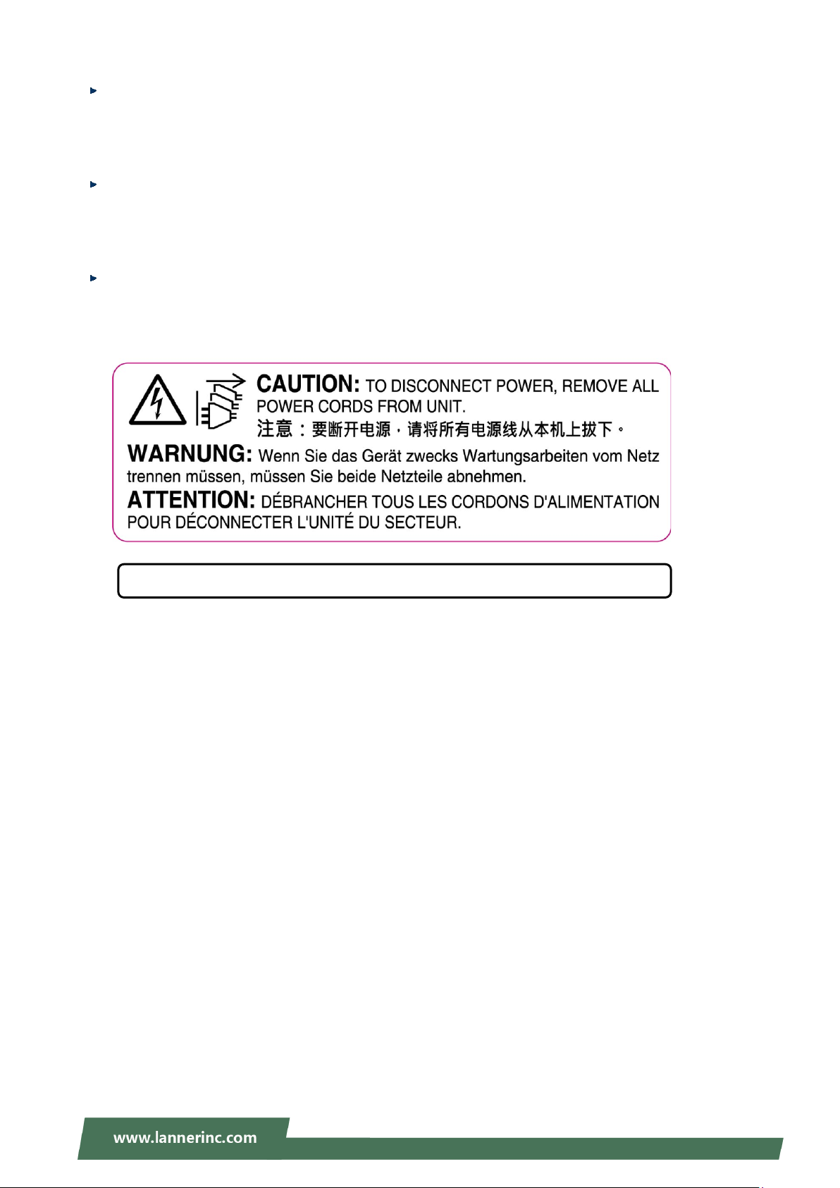
Disconnect all power by turning off the power and unplugging the power cord before installing or
removing a chassis or working near power supplies
Do not work alone if potentially hazardous conditions exist.
Never assume that power is disconnected from a circuit; always check the circuit.
Consignes de sécurité
Suivez ces consignes pour assurer la sécurité générale :
Laissez la zone du châssis propre et sans poussière pendant et après l’installation.
Ne portez pas de vêtements amples ou de bijoux qui pourraient être pris dans le châssis. Attachez votre
cravate ou écharpe et remontez vos manches.
Portez des lunettes de sécurité pour protéger vos yeux.
N’effectuez aucune action qui pourrait créer un danger pour d’autres ou rendre l’équipement
dangereux.
Coupez complètement l’alimentation en éteignant l’alimentation et en débranchant le cordon
d’alimentation avant d’installer ou de retirer un châssis ou de travailler à proximité de sources
d’alimentation.
Ne travaillez pas seul si des conditions dangereuses sont présentes.
Ne considérez jamais que l’alimentation est coupée d’un circuit, vérifiez toujours le circuit. Cet appareil
génère, utilise et émet une énergie radiofréquence et, s’il n’est pas installé et utilisé conformément aux
instructions des fournisseurs de composants sans fil, il risque de provoquer des interférences dans les
communications radio.
Lithium Battery Caution
There is risk of explosion if the battery is replaced by an incorrect type.
Dispose of used batteries according to the instructions.
Installation should be conducted only by a trained electrician or only by an electrically trained person
who knows all installation procedures and device specifications that are to be applied.
Do not carry the handle of power supplies when moving to another place.
Please conform to your local laws and regulations regarding safe disposal of lithium battery.
Disposal of a battery into fire or a hot oven, or mechanically crushing or cutting of a battery can result in
an explosion.
Leaving a battery in an extremely high temperature environment can result in an explosion or the
leakage of flammable liquid or gas.
A battery subjected to extremely low air pressure may result in an explosion or the leakage of flammable
liquid or gas.
Avertissement concernant la pile au lithium
Risque d’explosion si la pile est remplacée par une autre d’un mauvais type.
Jetez les piles usagées conformément aux instructions.
L’installation doit être effectuée par un électricien formé ou une personne formée à l’électricité
connaissant toutes les spécifications d’installation et d’appareil du produit.
Ne transportez pas l’unité en la tenant par le câble d’alimentation lorsque vous déplacez l’appareil.
6
Page 7

NCA-1513 User Manual
Operating Safety
Electrical equipment generates heat. Ambient air temperature may not be adequate to cool equipment
to acceptable operating temperatures without adequate circulation. Be sure that the room in which you
choose to operate your system has adequate air circulation.
Ensure that the chassis cover is secure. The chassis design allows cooling air to circulate effectively. An
open chassis permits air leaks, which may interrupt and redirect the flow of cooling air from internal
components.
Electrostatic discharge (ESD) can damage equipment and impair electrical circuitry. ESD damage occurs
when electronic components are improperly handled and can result in complete or intermittent failures.
Be sure to follow ESD-prevention procedures when removing and replacing components to avoid these
problems.
Wear an ESD-preventive wrist strap, ensuring that it makes good skin contact. If no wrist strap is
available, ground yourself by touching the metal part of the chassis.
Periodically check the resistance value of the antistatic strap, which should be between 1 and 10
megohms (Mohms).
Sécurité de fonctionnement
L’équipement électrique génère de la chaleur. La température ambiante peut ne pas être adéquate pour
refroidir l’équipement à une température de fonctionnement acceptable sans circulation adaptée.
Vérifiez que votre site propose une circulation d’air adéquate.
Vérifiez que le couvercle du châssis est bien fixé. La conception du châssis permet à l’air de
refroidissement de bien circuler. Un châssis ouvert laisse l’air s’échapper, ce qui peut interrompre et
rediriger le flux d’air frais destiné aux composants internes.
Les décharges électrostatiques (ESD) peuvent endommager l’équipement et gêner les circuits
électriques. Des dégâts d’ESD surviennent lorsque des composants électroniques sont mal manipulés et
peuvent causer des pannes totales ou intermittentes. Suivez les procédures de prévention d’ESD lors du
retrait et du remplacement de composants.
Portez un bracelet anti-ESD et veillez à ce qu’il soit bien au contact de la peau. Si aucun bracelet n’est
disponible, reliez votre corps à la terre en touchant la partie métallique du châssis.
Vérifiez régulièrement la valeur de résistance du bracelet antistatique, qui doit être comprise entre 1 et
10 mégohms (Mohms).
Mounting Installation Precautions
The following should be put into consideration for rack-mount or similar mounting installations:
Do not install and/or operate this unit in any place that flammable objects are stored or used in.
The installation of this product must be performed by trained specialists; otherwise, a non-specialist
might create the risk of the system’s falling to the ground or other damages.
Lanner Electronics Inc. shall not be held liable for any losses resulting from insufficient strength for
supporting the system or use of inappropriate installation components.
Elevated Operating Ambient - If installed in a closed or multi-unit rack assembly, the operating ambient
temperature of the rack environment may be greater than room ambient. Therefore, consideration
should be given to installing the equipment in an environment compatible with the maximum ambient
temperature (Tma) specified by the manufacturer.
Reduced Air Flow - Installation of the equipment in a rack should be such that the amount of airflow
required for safe operation of the equipment is not compromised.
Mechanical Loading - Mounting of the equipment in the rack should be such that a hazardous condition
is not achieved due to uneven mechanical loading.
Circuit Overloading - Consideration should be given to the connection of the equipment to the supply
circuit and the effect that overloading of the circuits might have on overcurrent protection and supply
wiring. Appropriate consideration of equipment nameplate ratings should be used when addressing this
concern.
Reliable Grounding - Reliable grounding of rack-mounted equipment should be maintained. Particular
7
Page 8

attention should be given to supply connections other than direct connections to the branch circuit (e.g.,
use of power strips).
Electrical Safety Instructions
Before turning on the device, ground the grounding cable of the equipment. Proper grounding
(grounding) is very important to protect the equipment against the harmful effects of external noise and to
reduce the risk of electrocution in the event of a lightning strike. To uninstall the equipment, disconnect
the ground wire after turning off the power. A ground wire is required and the part connecting the
conductor must be greater than 4 mm2 or 10 AWG.
Consignes de sécurité électrique
Avant d’allumer l’appareil, reliez le câble de mise à la terre de l’équipement à la terre.
Une bonne mise à la terre (connexion à la terre) est très importante pour protéger l’équipement contre
les effets néfastes du bruit externe et réduire les risques d’électrocution en cas de foudre.
Pour désinstaller l’équipement, débranchez le câble de mise à la terre après avoir éteint l’appareil.
Un câble de mise à la terre est requis et la zone reliant les sections du conducteur doit faire plus de 4
mm2 ou 10 AWG.
Grounding Procedure for DC Power Source
Loosen the screw of the earthing point.
Connect the grounding cable to the ground.
The protection device for the DC power source must provide 30
A current.
This protection device must be connected to the power source
before DC power.
Procédure de mise à la terre pour source
d’alimentation CC
Desserrez la vis du terminal de mise à la terre.
Branchez le câble de mise à la terre à la terre.
L’appareil de protection pour la source d’alimentation CC
doit fournir 30 A de courant.
Cet appareil de protection doit être branché à la source
d’alimentation avant l’alimentation CC.
8
Page 9
NCA-1513 User Manual
Instruction for the installation of the conductor to building earth by a skilled person.
This equipment must be grounded. The power cord for product should be connected to a socket-outlet
with earthing connection.
Cet équipement doit être mis à la terre. La fiche d'alimentation doit être connectée à une prise de terre
correctement câblée
Suitable for installation in Information Technology Rooms in accordance with Article 645 of the National
Electrical Code and NFPA 75.
Peut être installé dans des salles de matériel de traitement de l'information conformément à l'article 645
du National Electrical Code et à la NFPA 75.
The machine can only be used in a restricted access location and has installation instructions by a skilled
person (for Fan side).
Les matériels sont destinés à être installés dans des EMPLACEMENTS À ACCÈS RESTREINT.
9
Page 10

Table of Contents
Chapter 1: Product Overview .......................................................... 11
Package Content ......................................................................................................................... 11
Optional Kits ............................................................................................................................... 11
Ordering Information ................................................................................................................. 11
System Specifications ................................................................................................................. 12
Front Panel ................................................................................................................................. 13
Rear Panel ................................................................................................................................... 14
Motherboard Information .......................................................................................................... 15
Chapter 2 Hardware Installation..................................................... 24
Installing Nano SIM Card ............................................................................................................ 25
Mounting an SMA-Mount Antenna Cable Assembly ................................................................. 26
Rack-mounting the System ........................................................................................................ 27
Chapter 3 Software Setup ............................................................... 29
BIOS Setup .................................................................................................................................. 29
Appendix A: LED Indicator Explanations ....................................... 72
Appendix B: Network Interface Renaming ..................................... 73
Prerequisite ................................................................................................................................ 73
Description ................................................................................................................................. 73
Config(rnif.conf) ......................................................................................................................... 73
Appendix C: Terms and Conditions ................................................ 78
Warranty Policy .......................................................................................................................... 78
RMA Service ................................................................................................................................ 78
RMA Service Request Form ........................................................................................................ 79
10
Page 11
NCA-1513 User Manual
SKU No.
Main Features
NCA-1513A
Atom 4C C3558 w/QAT + 6x GbE RJ45 with 2 pair bypass function
NCA-1513B
Atom 2C C3308 w/QAT+ 6x GbE RJ45 with 2 pair bypass function
NCA-1513C
Atom 2C C3338 w/o QAT + 4x GbE RJ45 without bypass function
NCA-1513D
Atom 4C C3558 w/QAT +2x SFP + 4x GbE RJ45 with 2 pair bypass function
NCA-1513
Power Cord
CHAPTER 1: PRODUCT OVERVIEW
NCA-1513 series is an Intel ATOM based system desktop platform, based on 4-Core CPU with max 6x GbE
copper ports or 4xGbE + 2x SFP ports (by SKU). The system is targeted at low-cost desktop with ECC or
Non-ECC DDR4 memory support.
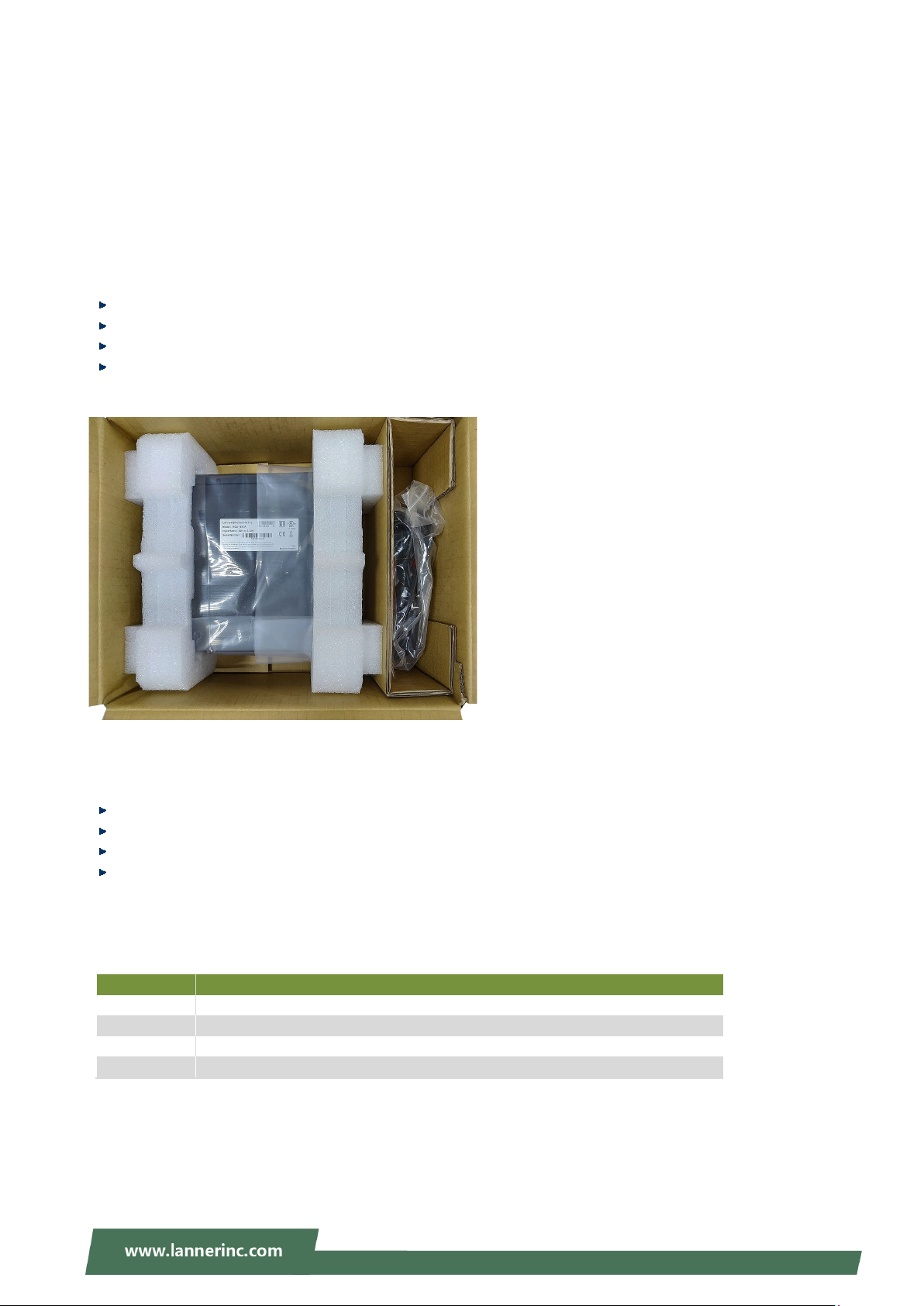
Package Content
Your package contains the following items:
1 x NCA-1513 series Network Security Platform
1 x Power cord(Default US Type)
1 x 40W power adaptor
1 Accessory Pack including 4 x Rubber foot + 1 x Plastic Spacer + 3 x Screw
Optional Kits
Ear Bracket with adaptor Holder kit
HDD Kit
WIFI Kit
LTE Kit
Ordering Information
Power Adapter
Accessory Pack
11
Page 12

System Specifications
Form Factor
Desktop
SKU A/D: Intel Atom C3558, 2.2GHz
SKU C: Intel Atom C3338, 1.5GHz
CPU Socket
1x BGA
Chipset
N/A
Security Acceleration
Intel® QuickAssist Technology (SKU A/B/D)
BIOS
AMI SPI Flash BIOS
DDR4 2133MHz ECC / Non-ECC (1866MHz
for C3308/C3338; 2133MHz for C3558)
Max. Capacity
16GB
DIMM )
SKU A: 6x GbE RJ45 (4x Marvell 88E1543 +
(4x Marvell 88E1543 +2x Intel i210-IS)
Bypass
SKU A/B/D: 2 pair bypass
NIC Module Slot
N/A
IO Interface
N/A
OPMA slot
N/A
Reset Button
1
LED
Power/Status/HDD/LAN
Power Button
1x Power Switch
Console
1x RJ45
LCD Module
N/A
Display
N/A
Power input
12V DC power inlet
HDD/SSD Support
1x 2.5” HDD/SSD Internal Bays
Onboard Slots
1x M.2 (w/ SATA support)
1x M.2 2280/2242 B Key for storage
1x M.2 3042 (USB3.0) for LTE
mini-PCIe
1x Mini-PCIe (PCIe/USB2.0)
SIM card Slot
1x Nano SIM Slot
Watchdog
Yes
Internal RTC with Li Battery
Yes
TPM
Yes (Optional)
Cooling
System
1x system FAN with Smart FAN function
0~40ºC Operating
-20~70ºC Non-Operating
5~90% Operating
5~ 95% Non-Operating
(WxDxH)
231mm x 200mm x 44mm
Weight
TBD
(WxDxH)
TBD
Weight
TBD
Type/Watts
12V power connector x1
Input
AC 100-240V~50-60Hz 1.7A
Approvals and Compliance
CE/FCC Class B, EU RoHS 2.0, China RoHS
Chapter 1: Product Overview
Platform
System Memory
Networking
LOM
Processor Options
Technology
Socket
Ethernet Ports (By SKU)
SKU B: Intel Atom C3308, 1.6GHz
1x 260-pin SO-DIMM (one channel one
2x Intel i210-AT)
SKU B: 6x GbE RJ45 (4x Marvell 88E1543 +
2x Intel i211-AT)
SKU C: 4x GbE RJ45 (4x Marvell 88E1543)
SKU D: 4x GbE RJ45 + 2x 10G SFP
I/O Interface
Storage
Expansion
Miscellaneous
Environmental Parameters
System Dimensions
Package Dimensions
USB 2x USB 3.0 or 2x USB 2.0 (by SKU)
M.2
Temperature
Humidity (RH)
Power
12
Page 13
NCA-1513 User Manual
F1
F2
System Power
LAN Ports
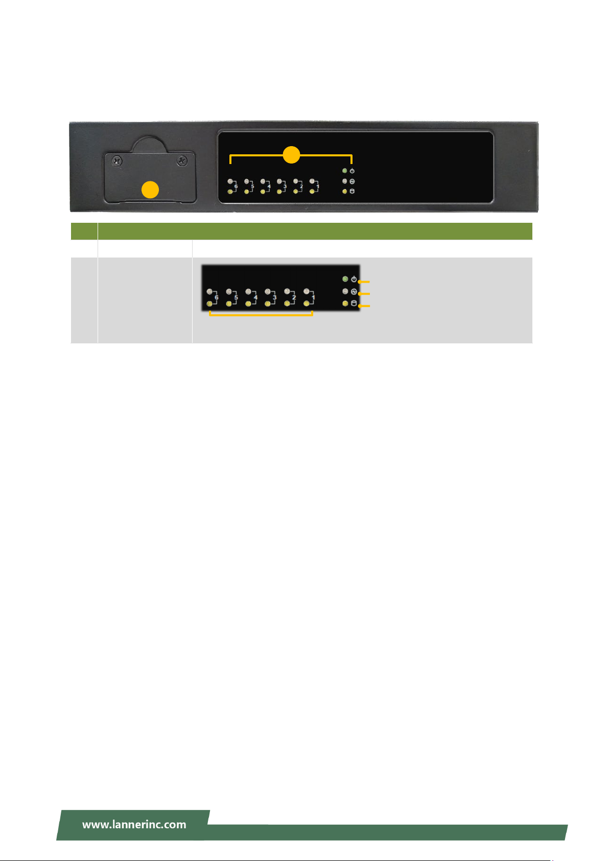
Front Panel
No. Description
F1 SIM Card Slot
1x Nano SIM Slot
F2 LED Indicators
System Status
HDD Activity
13
Page 14
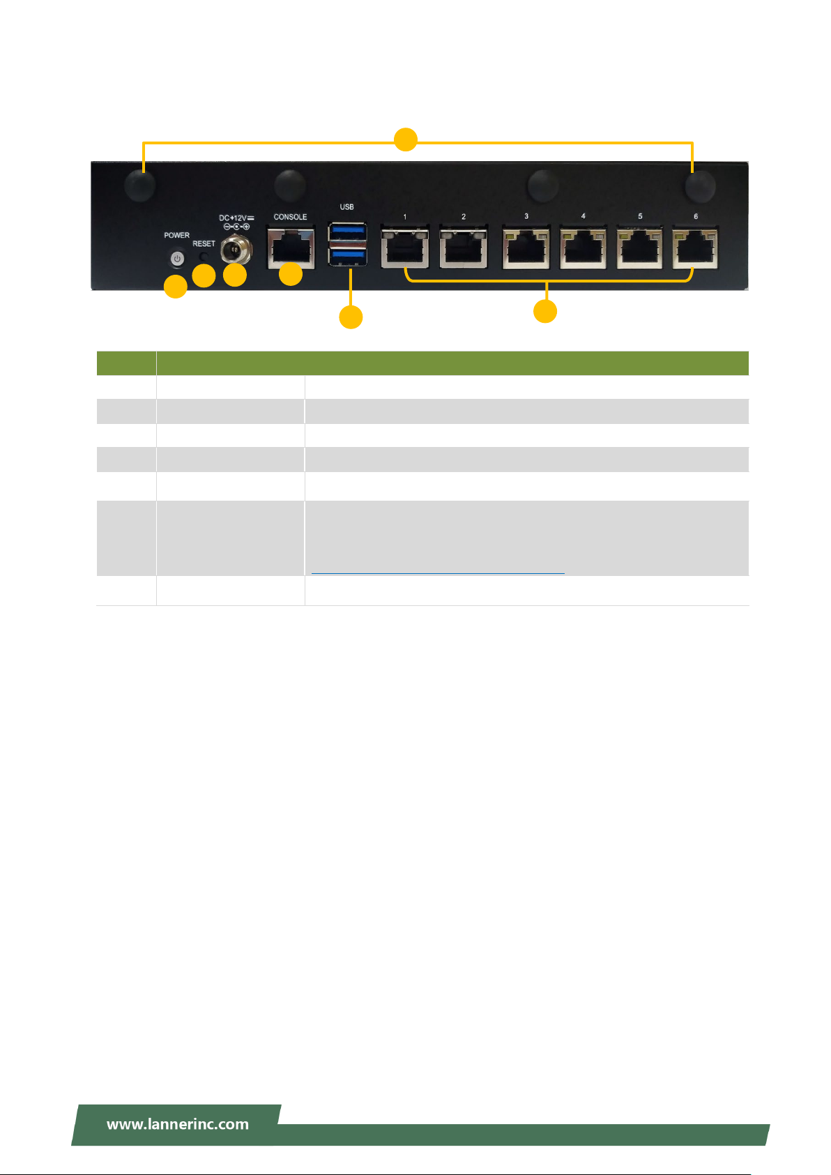
Rear Panel
For hardware reset
6x RJ45 Port or 2x SFP Port + 4x RJ45 Port (by SKU)
Appendix B: Renaming Network Interface
R2
R4
R5 R3R6
R1
R7
No. Description
R1 Power Switch 1x Power Button
R2 Reset Button
R3 DC Jack 1x DC Power Jack
R4 Console Port 1x RJ45 console port
Chapter 1: Product Overview
R5 USB Port 2x USB 3.0 Port or 2x USB 2.0 Port (by SKU)
R6 LAN Port
R7 Antenna Port 4x Reserved antenna port for Wi-Fi / LTE module
Port Sequence (from left to right): 213456
For instructions on modifying the port sequence, please refer to
14
Page 15
NCA-1513 User Manual
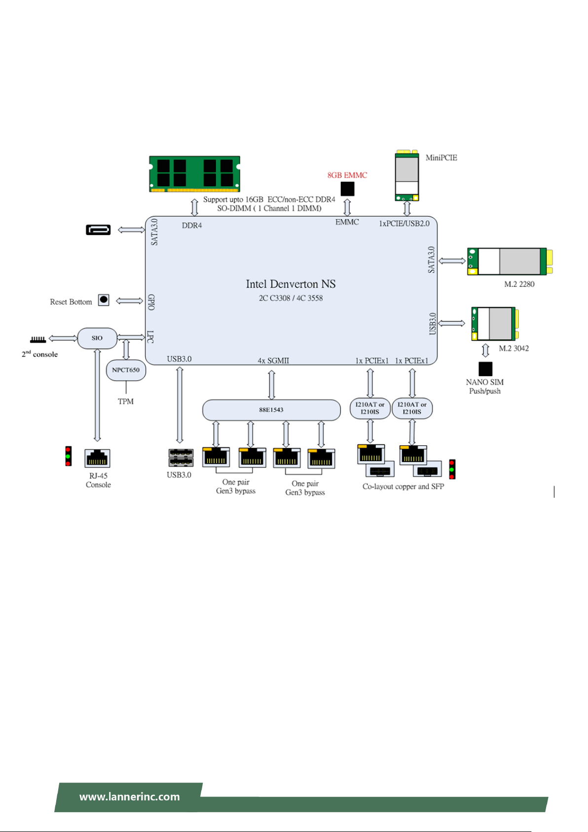
Motherboard Information
Block Diagram
The block diagram indicates how data flows among components on the motherboard. Please refer to the
following figure for your motherboard’s layout design.
15
Page 16
Chapter 1: Product Overview
FFAANN22
SSIIMM22
MMPPCCIIEE11
SSAATTAA11
CCOONN11
GGPPIIOO11
JJ8800PPOORRTT11
JJOOPPEENN11
CCOOMMBB22
JJ88 CCOONN22
MM22__LLTTEE
MM22_SSTTOORRAAGGEE
JJRRTTCC11
JJRRTTCC22
BBAATT11
JJSSPPIIRROOMM11
SSWW33
SSWW22
JJRREESSEETT11
CCOONNNN22
DDDDRR44
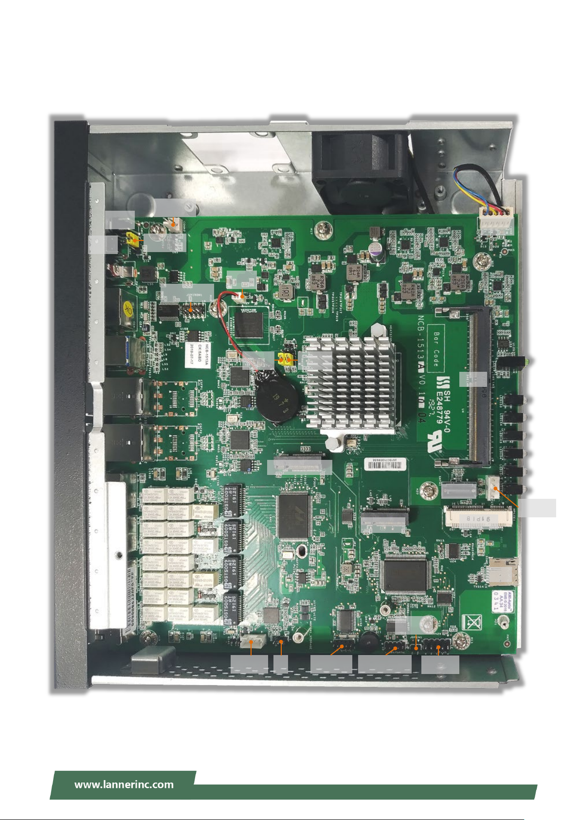
Jumper Setting and Pin Assignment
The motherboard board layout shows the connectors on the board. Refer to the below picture as a
reference of the pin assignments.
16
Page 17

NCA-1513 User Manual
BAT1: RTC Battery connector
PIN Description
1
2
COM1: Console port
PIN Description
1
2
3
4
5
6
7
8
COMB2: Internal COM port for debug
PIN Description PIN Description
V_BATTERY
GND
COM1_RTS_N
COM1_DTR_N
COM1_TXD
LGND
LGND
COM1_RXD
COM1_DSR_N
COM1_CTS_N
1
3
5
7
9
CON1: SATA power connector
PIN Description
1
2
3
4
CON2: Gen3 bypass flash connector
PIN Description
1
NDCD2-
NRXD2
NTXD2
NDTR2-
IOGND2
P12V_SB
GND
GND
P5V_AUX
P3V3_AUX
2
4
6
8
10
NDSR2-
NRTS2NCTS2-
NRI2-
NC
2
3
4
IO_RXD
GND
IO_TXD
17
Page 18

CONN2: Power pin header
7
GPO_B_4-
8
GPI_B_4
PIN Description
Chapter 1: Product Overview
1
2
FAN2: CPU FAN
PIN Description
5
4
3
2
1
GPIO1: GPIO connector
PIN Description PIN Description
1
3
GND
PWRON#
CPUFANOUT
NC
CPUFANIN
P12V_S
GND
GPO_B_1-
GPO_B_2
2
4
GPI_B_1
GPI_B_2
5
9
J8: Gen3 bypass flash jumper for ARM Programming Selection
0(2- 3) : Enable
1(1-2) : Disable (default)
PIN Description
1
2
3
J80PORT1: PORT80 connector
PIN Description PIN Description
1
3
GPO_B_3
GND
P3V3_AUX
PIO0_1
GND
CLK_LPC_OUT
80PORT_RST#
2
4
6
10
SOC_LPC_LAD1
SOC_LPC_LAD0
GPI_B_3
GND
5
7
9
SOC_LPC_FRAME_N
SOC_LPC_LAD3
SOC_LPC_LAD2
6
8
10
P3V3_S
NC
GND
18
Page 19

NCA-1513 User Manual
JOPEN1: Case open connector
PIN Description
1
2
JRESET1: H/W & S/W Reset
1-2 :Hardware Reset
2-3 :Software Reset (Default)
PIN Description
1
2
3
JRTC1: Clear CMOS
1-2 : NORMAL
2-3 : CLEAR RTC
PIN Description
1
2
3
SIO_CASEOPEN0_N
GND
FP_RST_BTN_N
GND
SW_RST_GP_N
P3V3_RTC
SOC_SRTCRST_N
GND
JRTC2: Clear CMOS
1-2 : NORMAL
2-3 : CLEAR RTC
PIN Description
1
2
3
JSPIROM1: Flash BIOS connector
PIN Description PIN Description
1
3
5
7
9
P3V3_RTC
SOC_RTEST_N
GND
SPI_HD1#
SOC_SPI_CS0_R
SPI_MISO_DUAL_R
NC
GND
2
4
6
8
10
P3V3_SB_SPI
SPI_HOLD0_L
SPI_CLK_DUAL_R
SPI_MOSI_DUAL_R
NC
19
Page 20
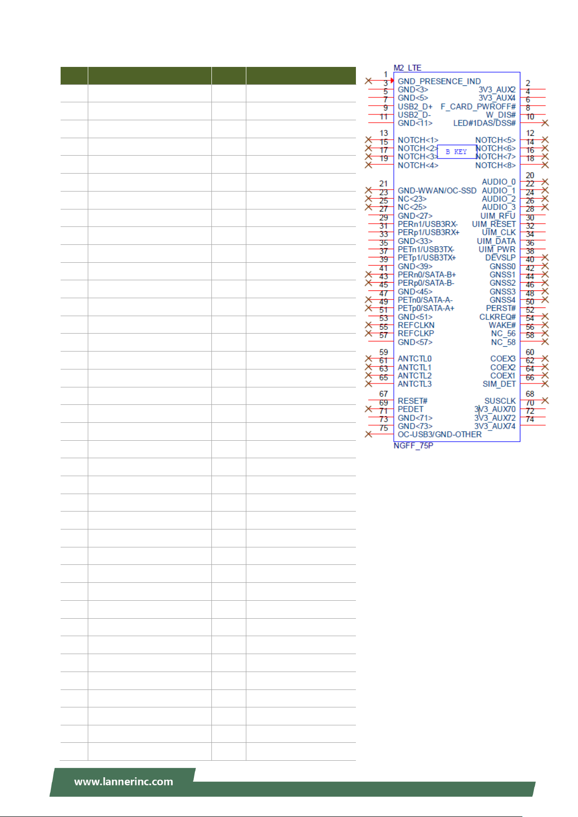
M2_LTE: M.2 con (Only LTE)
7
USB1_SB_L_DP
8
W_DIS#
17
NC
18
NC
23
NC
24
NC
29
USB3_HRX_L_DTX_N16
30
UIM1_RST1
35
USB3_HTX_L_DRX_N16
36
UIM1_PWR
41
NC
42
NC
45
GND
46
NC
57
GND
58
NC
63
NC
64
NC
69
NC
70
P3V3_AUX
75
NC
PIN Description PIN Description
1 NC 2 P3V3_AUX
3 GND 4 P3V3_AUX
5 GND 6 PWROFF#
9 USB1_SB_L_DN 10 NC
11 GND 12 NC
13 NC 14 NC
15 NC 16 NC
19 NC 20 NC
21 NC 22 NC
25 NC 26 NC
Chapter 1: Product Overview
27 GND 28 UIM1_VPP1
31 USB3_HRX_L_DTX_P16 32 UIM1_CLK1
33 GND 34 UIM1_DAT1
37 USB3_HTX_L_DRX_P16 38 NC
39 GND 40 NC
43 NC 44 NC
47 NC 48 NC
49 NC 50 NGFF_LTE_RST#
51 GND 52 NC
53 NC 54 NC
55 NC 56 NC
59 NC 60 NC
61 NC 62 NC
65 NC 66 NC
67 P1V8_A 68 NC
71 GND 72 P3V3_AUX
73 GND 74 P3V3_AUX
20
Page 21
NCA-1513 User Manual
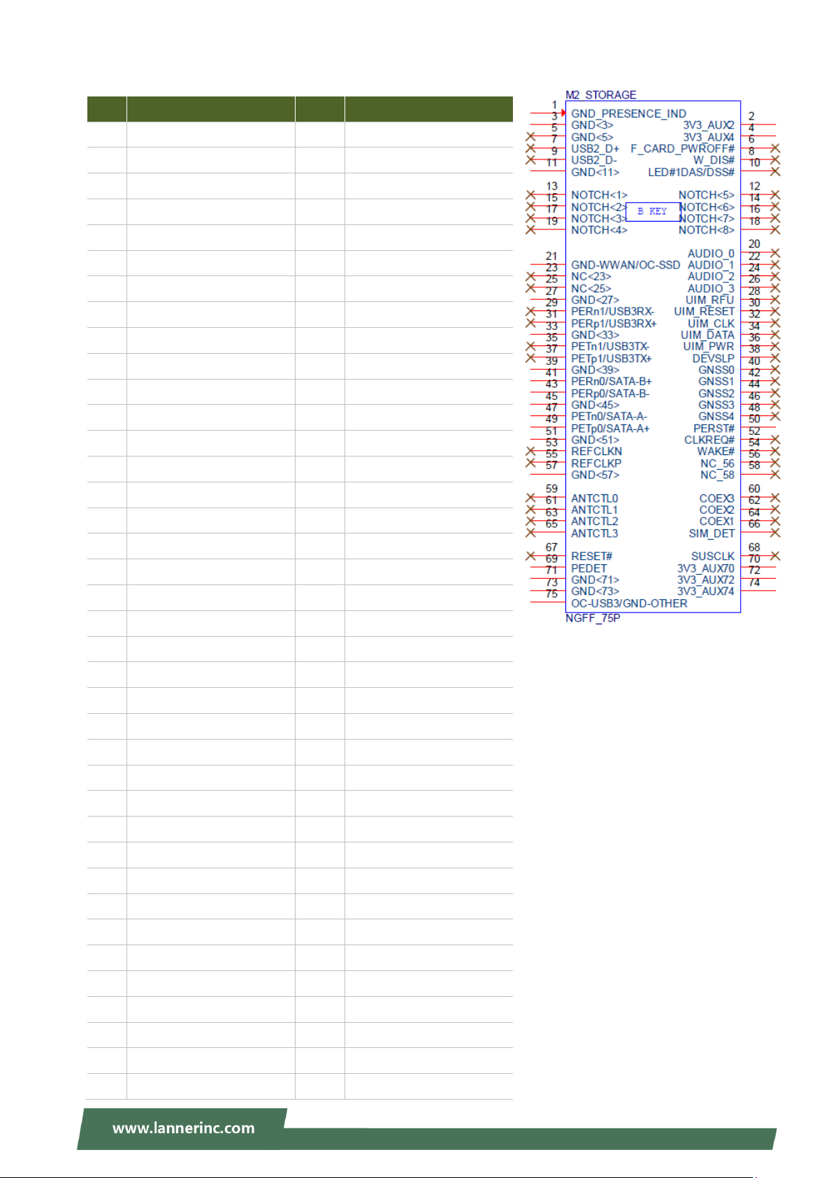
M2_STORAGE: M.2 storage connector (Only Storage)
PIN Description PIN Description
1
3
5
7
9
11
13
15
17
19
21
23
25
27
GND
GND
NC
NC
NC
GND
NC
NC
NC
NC
GND
NC
NC
GND
2
4
6
8
10
12
14
16
18
20
22
24
26
28
P3V3_AUX
P3V3_AUX
NC
NC
NC
NC
NC
NC
NC
NC
NC
NC
NC
NC
29
31
33
35
37
39
41
43
45
47
49
51
53
55
57
59
NC
NC
GND
NC
NC
GND
SATA_HRX_C_DTX_P4
SATA_HRX_C_DTX_N4
GND
SATA_HTX_C_DRX_N4
SATA_HTX_C_DRX_P4
GND
NC
NC
GND
NC
30
32
34
36
38
40
42
44
46
48
50
52
54
56
58
60
NC
NC
NC
NC
NC
NC
NC
NC
NC
NC
NGFF_STORAGE_RST#
NC
NC
NC
NC
NC
61
63
65
67
69
71
73
75
NC
NC
NC
NC
GND
GND
GND
GND
62
64
66
68
70
72
74
NC
NC
NC
NC
P3V3_AUX
P3V3_AUX
P3V3_AUX
21
Page 22
Chapter 1: Product Overview
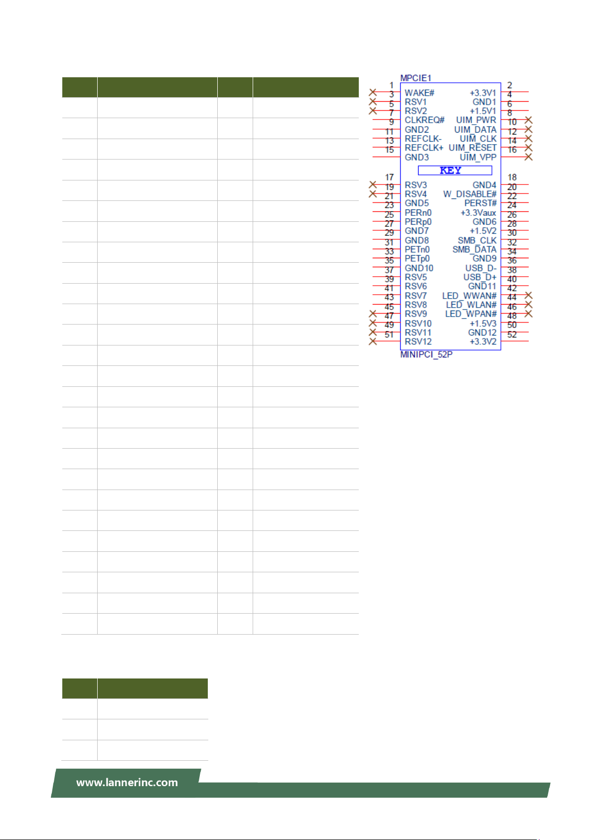
MPCIE1: Mini PCIE 52PIN
PIN Description PIN Description
1
3
5
7
9
11
13
15
17
19
21
23
25
CLKREQ_MPCIE_SLOT2
GND
CLK100_PCIE_SLOT1_4N
CLK100_PCIE_SLOT1_4P
GND
GND
PEX_RX5N
PEX_RX5P
NC
NC
NC
NC
NC
2
4
6
8
10
12
14
16
18
20
22
24
26
P3V3_AUX
GND
P1V5_A
NC
NC
NC
NC
NC
GND
P3V3_AUX
MINI_PCI_RST#
P3V3_AUX
GND
27
29
31
33
35
37
39
41
43
45
47
49
51
GND
GND
PEX_TX5N_C
PEX_TX5P_C
GND
GND
P3V3_AUX
P3V3_AUX
GND
NC
NC
NC
NC
28
30
32
34
36
38
40
42
44
46
48
50
52
P1V5_A
SMB_MPCIE_CLK
SMB_MPCIE_DATA
GND
USB2_P0_DN_L
USB2_P0_DP_L
GND
NC
NC
NC
P1V5_A
GND
P3V3_AUX
PW1: DC power connector
PIN Description
2
3
1
GND
GMD
P12V_SB
22
Page 23

NCA-1513 User Manual
SATA1: SATA connector
PIN
1
2
3
4
5
6
7
SIM2: M2_LTE SIM card slot
PIN Description PIN Description
C1
C2
C3
Description
GND
SATA_TX_DP0_C
SATA_TX_DN0_C
GND
SATA_RX_DN0_C
SATA_RX_DP0_C
GND
UIM1_PWR
UIM1_RST1
UIM1_CLK1
C4
C5
C6
UIM1_DAT1
UIM1_VPP1
GND
SW2: Reset Button
PIN Description PIN Description
4
2
SW3: Power Button
PIN Description PIN Description
4
3
L2
GND
GND
PWRON#
PWRON#
PRLED-
3
1
2
1
L1
SUSLED-
GND
SW_RST_GP_N
GND
GND
23
Page 24
Chapter 2 Hardware Installation
SIM
DDR4-2400
or Non-ECC
M.2 2280/2242
M.2 3042
USB3.0
mPCIE
PCIe/USB2.0 signal
Nano SIM
For M.2 LTE
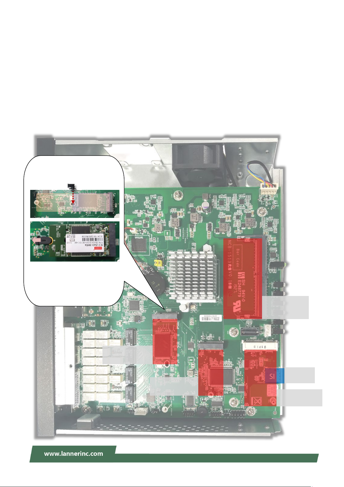
For 2242 M.2 SSD module, insert
To secure the module, pull the clip of
After you
to fasten the card.
CHAPTER 2 HARDWARE INSTALLATION
To reduce the risk of personal injury, electric shock, or damage to the equipment, please remove all power
connections to completely shut down the device. Also, please wear ESD protection gloves when conducting
the steps described hereafter.
This system supports multiple wireless connectivity methods with two M.2 slots and an MPCIE slot. Based
on your application and modules used, install modules in the corresponding slots.
the plastic spacer into the
mounting hole on MB to secure the
module.
2280 2242
the spacer open while pressing
down on the card.
release the clip, it will bounce back
SATA signal (B key)
M.2
(SSD)
signal (B key)
M.2
(LTE)
System
Memory
Up to 16GB ECC
Mini-PCIe
(Wi-fi)
24
Page 25

NCA-1513 User Manual
Installing Nano SIM Card
The SIM slot on front panel supports an LTE module. The SIM socket supports the push-push mechanism,
allowing inserting and ejecting the SIM card to be as easy as one push.
1. Loosen the two screws that secure the SIM slot cover and remove the slot cover. With the angled
corner facing inward, push the SIM card all the way in until it clicks into place.
2. To remove the SIM card, use your fingertip to push it a little to have the card automatically ejected.
25
Page 26

Chapter 2 Hardware Installation
SMA Female
Bulkhead
Washer
Nut
Mounting an SMA-Mount Antenna Cable Assembly
To mount the Wi-Fi/LTE antennas:
1. Take out the antenna pigtail cable from the Antenna Kit. From inside the chassis, insert the SMA Female
Bulkhead through the antenna hole on the panel.
2. From outside the panel, attach the Washer and Nut, and tighten the Nut using an SMA Torque Wrench.
Warning: Do not use any tool other than an SMA Torque Wrench to fasten the Nut. For
example, general pliers or tweezers without limited twisting force are very likely to cause the
distortion of SMA connector.
26
Page 27

NCA-1513 User Manual
bracket to the screw holes on the side
Ear Bracket
Adapter Bracket
1
Screws
Screws
(for Rack-mounting)
Rack-mounting the System
With the rack mount kit, this system can be fixed onto rack posts. Please contact Lanner‘s sales
representative for purchasing this kit.
What’s in the Rack-mount Kit
Check the kit for the following items:
2x Ear Bracket
1x Adapter Bracket
1x Adapter Holder
Screws for the fixture of the Brackets and
the Holder
Rack-mounting Screws
Attaching the Assembly to the Chassis
1. On one side of the system, align the ear
panel and fix it using three screws.
2. Secure the other ear bracket to the other
side of the system.
3. Fix the adapter holder to the left side panel using two screws.
4. The adapter holder assembly is designed to secure a 5V adapter or a 3V adapter. Secure the adapter
onto the holder with the adapter bracket and two
bracket is as shown in the picture.
5. Attach the power adapter’s connector to the power supply jack on the system’s rear panel.
6. Secure the adapter’s cable onto the adapter holder.
provided screws. Make sure the way you place the
27
Page 28

Chapter 2 Hardware Installation
Installing the System to the Rack
In the rack, install a shelf to support the system (recommended). Hold the system with its front facing you,
lift and carefully insert the system into the rack. Attach the brackets to the rail rack using rack-mounting
screws and/or retainer nuts.
28
Page 29

NCA-1513 User Manual
CHAPTER 3 SOFTWARE SETUP
BIOS Setup
BIOS is a firmware embedded on an exclusive chip on the system’s motherboard. Lanner's BIOS firmware
offering including market-proven technologies such as Secure Boot and Intel Boot Guard technology
deliver solid commitments for the shield protection against malware, uncertified sequences and other
named cyber threats. BIOS update for Lanner PCs are available for download at
http://www.lannerinc.com/products/firmware-and-software/securityenhanced-bios
Main Setup
To enter the BIOS setup utility, simply follow the steps below:
1. Boot up the system.
2. Pressing the <Tab> or <Del> key immediately allows you to enter the Setup utility, and then you will
be directed to the BIOS main screen. The instructions for BIOS navigations are as below:
Control Keys Description
<Enter> select an item/option or enter a sub-menu
+/- adjust values for the selected setup item/option
F1 display General Help screen
F2
F3 load optimized default values
F4 save configurations and exit BIOS
<Esc> exit the current screen
select a setup screen
select an item/option on a setup screen
retrieve previous values, such as the last configured parameters during the last
time you entered BIOS
29
Page 30

Setup main page contains BIOS information and project version information.
Feature
Description
Access Level: Administrator / User
To set the Date, use <Tab> to switch between Date elements.
Days: dependent on Month.
System Tine
To set the Date, use <Tab> to switch between Date elements.
Chapter 3 Software Setup
BIOS
Information
System Date
BIOS Vendor: American Megatrends
Core Version: AMI Kernel version, CRB code base, X64
Compliancy: UEFI version, PI version
Project Version: BIOS release version
Build Date and Time: MM/DD/YYYY
Default Range of Year: 2005-2099
Default Range of Month: 1-12
30
Page 31

NCA-1513 User Manual
Advanced Page
Select the Advanced menu item from the BIOS setup screen to enter the “Advanced” setup screen. Users
can select any of the items in the left frame of the screen.
31
Page 32

Trusted Computing
Chapter 3 Software Setup
32
Page 33

NCA-1513 User Manual
Feature Options Description
Enables or disables BIOS support for security device.
Security Device
Support
SHA-1 PCR Bank
SHA256 PCR Bank
Pending
operation
Platform
Hierarchy
Storage Hierarchy
Endorsement
Hierarchy
Enabled
Disabled
Enabled
Disabled
Enabled
Disabled
None
TPM Clear
Enabled
Disabled
Enabled
Disabled
Enabled
Disabled
By disabling this function, OS will not show Security
Device. TCG EFI protocol and INT1A interface will not
be available.
Enables or disables SHA-1 PCR Bank.
Enables or disables SHA256 PCR Bank.
Schedules an Operation for the Security Device. NOTE:
Your computer will reboot during restart in order to
change State of Security Device.
Enables or disables Platform Hierarchy.
Enables or disables Storage Hierarchy.
Enables or disables Endorsement Hierarchy.
TPM2.0 UEFI Spec
Version
Physical Presence
Spec Version
TPM 20
InterfaceType
Device Select
TCG_1_2
TCG_2
1.2
1.3
TIS
TPM 1.2
TPM 2.0
Auto
Select the TCG2 Spec Version,
TCG_1_2: Supports the Compatible mode for
Win8/Win10
TCG_2: Supports new TCG2 protocol and event format
for Win10 or later.
Select to tell OS to support PPI Spec Version 1.2 or 1.3.
NOTE: Some HCK tests might not support 1.3.
Select TPM 20 Device for the Communication
Interface.
TPM 1.2 will restrict support to TPM 1.2 devices; while
TPM 2.0 will restrict support to TPM 2.0 devices; Auto
will support both with the default set to TPM 2.0
devices. If not found, TPM 1.2 devices will be
enumerated.
33
Page 34

Super IO Configuration
Chapter 3 Software Setup
34
Page 35

NCA-1513 User Manual
Serial port 1 Configuration
Feature Options Description
Serial Port
Enabled
Disabled
Device Settings NA IO=3F8h; IRQ = 7
Enables or disables Serial Port 1.
35
Page 36

Serial port 2 Configuration
Chapter 3 Software Setup
Feature Options Description
Serial Port Enabled
Disabled
Device Settings NA IO=2F8h; IRQ = 10
Enable or Disable Serial Port 2.
36
Page 37

NCA-1513 User Manual
H/W Monitor
37
Page 38

Watch Dog Timer Configuration
Chapter 3 Software Setup
Feature Options Description
Watch Dog Timer Enabled
Disabled
Enables or disables Watch Dog Timer function
38
Page 39

NCA-1513 User Manual
Digital I/O Configuration
Feature Options Description
Digital I/O Output 1
Digital I/O Output 3
Digital I/O Output 5
Digital I/O Output 7
Output Low
Output High
Output Low
Output High
Output Low
Output High
Output Low
Output High
Configure Digital I/O Pin1
Configure Digital I/O Pin3
Configure Digital I/O Pin5
Configure Digital I/O Pin7
39
Page 40

Status LED Configuration
Chapter 3 Software Setup
Feature Options Description
OFF
Status LED
GREEN
RED
Configures Status LED color
40
Page 41

NCA-1513 User Manual
Feature
Options
Description
Redirection
Serial Port Console Redirection
COM0
Console
Enabled
Disabled
Enables or disables Console Redirection
41
Page 42

Console Redirection Settings
Feature
Options
Description
ANSI: Extended ASCII char set
9600
115200
8
None
Space
2
Flow Control
None
Flow Control can prevent data loss from
Chapter 3 Software Setup
Terminal Type
Bits per second
Data Bits
Parity
VT100
VT100+
VT-UTF8
ANSI
19200
38400
57600
7
Even
Odd
Mark
VT100: ASCII char set
VT100+:Extends VT100 to support color,
function keys, etc.
VT-UTF8:Uses UTF8 encoding to map
Unicode chars onto 1 or more bytes
Selects serial port transmission speed. The
speed must be matched on the other side.
Long or noisy lines may require lower speeds.
Data Bits
A parity bit can be sent with the data bits to
detect some transmission errors.
Stop Bits
1
Indicates the end of a serial data packet.
42
Page 43

NCA-1513 User Manual
RTS/CTS
Key Support
Enabled
for ANSI/VT100 terminals
Disabled
Enabled
With this mode enabled, only text will be
sent. This is to capture Terminal data.
VT400
Hardware
buffer overflow.
VT-UTF8 Combo
Disabled
Recorder Mode
VT100
LINUX
Putty KeyPad
XTERM86
SCO
ESCN
Enables VT-UTF8 Combination Key Support
Selects FunctionKey and KeyPad on Putty.
43
Page 44

Console Redirection Settings
Feature
Options
Description
80x24
80x25
On Legacy OS, the Number of Rows and
Columns supported redirection.
is set to Always Enable.
Chapter 3 Software Setup
Redirection COM
Port
COM0 Select a COM port to display redirection of Legacy
Resolution
Always
Redirection After
Enable
BIOS POST
BootLoader
OS and Legacy OPROM Messages.
When Bootloader is selected, Legacy Console
Redirection is disabled before booting to
legacy OS. When Always Enable is selected,
then Legacy Console Redirection is enabled
for legacy OS. Default setting for this option
44
Page 45

NCA-1513 User Manual
Enable or Disables 64bit capable Devices to be
Decoded in Above 4G Address Space (Only if
option enables or disables Single Root IO
PCI Subsystem Settings
Feature Options Description
Above 4G
Decoding
Feature Options Description
SR-IOV Support
Disabled
Enabled
System Supports 64 bit PCI Decoding).
If the system has SR-IOV capable PCIe Devices, this
Disabled
Enabled
Virtualization Support.
45
Page 46

Network Stack Configuration
Enables Ipv4 PXE Boot Support. If IPV4 is
Enables Ipv4 HTTP Boot Support. If IPV4 is
Enables Ipv6 PXE Boot Support. If IPV6 is
Enables Ipv6 HTTP Boot Support. If IPV6 is
Chapter 3 Software Setup
Feature Options Description
Network Stack
Ipv4 PXE Support
Ipv4 HTTP Support
Ipv6 PXE Support
Ipv6 HTTP Support
PXE boot wait time 0
Disabled
Enabled
Disabled
Enabled
Disabled
Enabled
Disabled
Enabled
Disabled
Enabled
Enables or disables UEFI Network Stack
disabled, PXE boot option will not be created.
disabled, HTTP boot option will not be created.
disabled, PXE boot option will not be created.
disabled, HTTP boot option will not be created.
Wait time to press <ESC> key to abort the PXE
boot
Media detect count 1
Number of times the presence of media will be
checked
46
Page 47

NCA-1513 User Manual
Determines OpROM execution policy for
devices other than Network, Storage, or
CSM Configuration
Feature Options Description
CSM Support
Network
Storage
Video
Other PCI device
Disabled
Enabled
Do Not Launch
UEFI
Legacy
Do Not Launch
UEFI
Legacy
Do Not Launch
UEFI
Legacy
Do Not Launch
UEFI
Legacy
Enables or disables CSM Support
Controls the execution of UEFI and Legacy
PXE OpROM
Controls the execution of UEFI and Legacy
Storage OpROM
Controls the execution of UEFI and Legacy
Video OpROM
Video
47
Page 48

SDIO Configuration
Auto Option: Access SD device in DMA mode if
controller supports it,otherwise in PIO mode.DMA
Chapter 3 Software Setup
Feature Options Description
Auto
SDIO Access
Mode
ADMA
SDMA
PIO
Option: Access SD device in DMA mode.PIO Option:
Access SD device in PIO mode..
48
Page 49

NCA-1513 User Manual
will keep USB devices
off support. The XHCI
ownership change should be claimed by
Enables or disables USB Mass Storage
USB mass storage device Start Unit
USB Configuration
Feature Options Description
Legacy USB Support
XHCI Hand-off
USB Mass Storage
Driver Support
USB transfer time-out
Enabled
Disabled
Auto
Enabled
Disabled
Enabled
Disabled
1 sec
5 sec
10 sec
Enables Legacy USB support.
Auto option disables legacy support if no
USB devices are connected;
Disabled option
available only for EFI applications.
This is a workaround for OSes without
XHCI hand-
XHCI driver.
Driver Support.
The time-out value for Control, Bulk, and
Interrupt transfers
Device reset time-out
20 sec
1 sec
5 sec
10 sec
20 sec
command time-out
49
Page 50

Chapter 3 Software Setup
it properly reports itself to the Host
Maximum time the device will take before
Device power-up delay
Auto
Controller. Auto uses default value: for a
Manual
Root port, it is 100 ms, for a Hub port the
delay is taken from Hub descriptor.
50
Page 51

NCA-1513 User Manual
Control Legacy PXE Boot
Feature Options Description
Control Legacy PXE
Boot From
Disabled
Lan3
Control Legacy PXE Boot from which
Lan4
Lan.
Lan5
Lan6
51
Page 52

NVME Configuration
Chapter 3 Software Setup
52
Page 53

NCA-1513 User Manual
IntelRCSetup
Select the IntelRCSetup menu item from the BIOS setup screen to enter the Platform Setup screen. Users
can select any of the items in the left frame of the screen.
Feature Options Description
Relax Security
Configuration
Restore On Power Loss Power On
Disable
Enabled
Power Off
Last State
Relaxes the security configuration to be
able to use BIOS update tool.
Specify what state to go to when power is
re-applied after a power failure (G3 state).
53
Page 54

Processor Configuration
Enables/Disable EIST. GV3 must be
This option only applies to ES2 and
Chapter 3 Software Setup
Feature Options Description
EIST (GV3)
Turbo
CPU C State
Package C state limit
Max core C-state
Disable
Enable
Enable
Disable
Disable
Enable
No Pkg C-state
No S0Ix
No limit
C1
C6
enable for Turbo.
.
Enable or Disable CPU Turbo capability.
above.
Enable the Enhanced Cx state of the CPU,
takes effect after reboot.
Package C state limit.
Options are:C1 and C6.
Enhanced Halt
State(C1E)
Monitor/Mwait Enable
L1 Prefetcher Enable
Disable
Enable
Disable
Disable
Enables the enhanced C1E state of the
CPU, takes effects after reboot.
Enable or Disable the Monitor/Mwait
Instruction.
Enable/Disable L1 Prefetch.
54
Page 55

NCA-1513 User Manual
enables, enable fast strings for
When disabled, forces the XD feature
L2 Prefetcher Enable
Enable/Disable L2 Prefetch
Disable
Fast String Disable
Machine Check Disable
Execute Disable Bit Disable
VMS Disable
AES-NI Disable
Enable
Enable
Enable
Enable
Enable
When
REP MOVS/STOS.
Enable or Disable the Machine Check.
flag to always return 0.
Enables the Vanderpool Technology,
takes effect after reboot.
Enable/disable AES-NI support.
55
Page 56

Server ME Configuration
Chapter 3 Software Setup
56
Page 57

NCA-1513 User Manual
which skips memory
training and attempts to boot using fast known
North Bridge Chipset Configuration
Feature Options Description
Enables/Disables fast boot,
good configuration.
DDR memory frequency:
DDR4 up to DDR-2666
DDR3 up to DDR-1867.
Option to enable /Disable VT-d.
Fast Boot
Memory
Frequency
VT-d Disable
Disabled
Enabled
DDR-1600
DDR-1867
DDR-2133
DDR-2400
Enable
57
Page 58

South Bridge Chipset Configuration
Chapter 3 Software Setup
58
Page 59

NCA-1513 User Manual
Enables/Disables SATA Controller if supported by
Indicates the highest allowable speed of the
SATA Configuration
Feature Options Description
Enable controller Enabled
Disabled
LPM Enabled
Disabled
ALPM Enabled
Disabled
Speed Limit Gen 1
Gen 2
Gen 3
current CPU sku
Enables/Disables Link Power Management
Enable/Disables Agresive Link Power Management
interface
59
Page 60

SATA1 Configuration
Chapter 3 Software Setup
Feature Options Description
Enable/disable port Enabled
Disabled
Hot plug Enabled
Disabled
Spin up Enabled
Disabled
Enables/Disables SATA Controller port if
supported by current cpu SKU.
Hot plug
Spin up
60
Page 61

NCA-1513 User Manual
M2SATA1 Configuration
Feature Options Description
Enable/disable port Enabled
Disabled
Hot plug Enabled
Disabled
Spin up Enabled
Disabled
Enables/Disables SATA Controller port if
supported by current cpu SKU.
Hot plug
Spin up
61
Page 62

PCIE IP Configuration
Chapter 3 Software Setup
Feature Options Description
Bifurcation PCIE0
Bifurcation PCIE1
Auto
X8
X4x4
X4x2x2
X2x2x4
X2x2x2x2
Auto
X8
X4x4
X4x2x2
X2x2x4
X2x2x2x2
Select and force Root Complex Bifurcation
Configuration regardless board or trident
detection.
Select and force Root Complex Bifurcation
Configuration regardless board or trident
detection.
62
Page 63

NCA-1513 User Manual
IQAT Configuration
Feature Options Description
IQAT Enabled
Disabled
Hides IQAT device from and OS.
63
Page 64

System Event Log
Enable/Disable Memory Error logging
Enable/Disable Correctable Memory
correctable Memory
Enable/Disable Error
Enable/Disable PCIe Error logging
Chapter 3 Software Setup
Feature Options Description
System Errors
Memory Elog Support
Parity Check
Log Correctable
Log Un-Correctable
Cloaking
PCIE Elog Support
Disable
Enable
Auto
Disable
Enable
Enable
Disable
Enable
Disable
Enable
Disable
Disable
Enable
Disable
Enable
System Error enabling and logging setup
option.
support
Enable/Disable Parity Check
Error logging support
Enable/Disable UnError logging support
Error Cloaking Feature to hide CE Error to
OS
support
Log Fatal Error
Log Non-Fatal Error
Log Correctable Error Disable Send system event Signal on Correctable
Disable
Enable
Disable
Enable
Send system event Signal on Fatal error
Send system event Signal on Non Fatal
error.
64
Page 65

NCA-1513 User Manual
reporting on all
enumerated Root ports, bridges and
Enable Parity Error reporting on all
enumerated Root ports, bridges and
type with address and vendor
Enable error.
PCIe System Error
PCIe Parity Error
WHEA Support
WHEA Error Injection
5.0 Extension
Whea Logging
WHEA PCIe Error
Injection
Disable
Enable
Disable
Enable
Disable
Enable
Disable
Enable
Disable
Enable
Disable
Enable
Enable System Error
devices.
devices .
Enable/Disable WHEA ACPI support.
When EINJ ACPI 5.0 support for set error
extensions.
Enable/Disable Whea logging of errors.
Enable/Disable WHEA PCIe Error
Injection .
65
Page 66

Chapter 3 Software Setup
If ONLY the Administrator's password is set, it only
limits access to Setup and is only asked for when
If ONLY the User's password is set, it serves as a
Security
Select the Security menu item from the BIOS setup screen to enter the Security Setup screen. Users can
select any of the items in the left frame of the screen.
Feature Description
Administrator Password
User Password
entering Setup.
power-on password and must be entered to boot or
enter Setup. In Setup, the User will have Administrator
rights.
66
Page 67

NCA-1513 User Manual
a physically present user without full
Secure Boot
Feature Options Description
Secure Boot
Enable
Secure Boot Mode
Disabled
Enabled
Standard
Custom
Secure Boot is activated when Platform Key(PK) is
enrolled, System mode is User/Deployed, and CSM
function is disabled.
Customizable Secure Boot mode: In Custom mode,
Secure Boot Policy variables can be configured by
authentication.
67
Page 68

Key Management
Allows the image to run in Secure Boot mode.
Chapter 3 Software Setup
Feature Options Description
Factory Key
Provision
Restore Factory
keys
Enroll Efi Image None
Disabled
Enabled
None
Provision factory default keys on next re-boot only
when System in Setup Mode.
Force System to User Mode. Configure NVRAM to
contain OEM-defined factory default Secure Boot
keys.
Enroll SHA256 hash of the binary into Authorized
Signature Database (db)
68
Page 69

NCA-1513 User Manual
Boot Menu
Select the Boot menu item from the BIOS setup screen to enter the Boot Setup screen. Users can select any
of the items in the left frame of the screen.
Feature Options Description
The number of seconds to wait for setup
Setup Prompt Timeout 5
Bootup NumLock State
Quiet Boot
Boot mode select
Choose boot priority from the boot option group.
Choose specifies boot device priority sequence from available Group device.
On
Off
Disabled
Enabled
LEGACY
UEFI
DUAL
activation key.
65535 means indefinite waiting.
Select the keyboard NumLock state
Enables or disables Quiet Boot option.
Select boot mode for LEGACY or UEFI.
69
Page 70

NCA-1513 User Manual
Save and Exit Menu
Select the Save and Exit menu item from the BIOS setup screen to enter the Save and Exit Setup screen.
Users can select any of the items in the left frame of the screen.
■ Save Changes and Reset
When Users have completed the system configuration changes, select this option to save the changes and
exit from BIOS Setup in order for the new system configuration parameters to take effect. The following
window will appear after selecting the “Save Changes and Exit” option. Select “Yes” to Save Changes and
Exit Setup.
■ Discard Changes and Exit
Select this option to quit Setup without saving any modifications to the system configuration. The following
window will appear after the “Discard Changes and Exit” option is selected. Select “Yes” to Discard
changes and Exit Setup.
70
Page 71

■ Restore Defaults
Note
Restore default values for all setup options. Select “Yes” to load Optimized defaults.
Chapter 3 Software Setup
: The items listed under Boot Override depend on devices connected to system.
71
Page 72

NCA-1513 User Manual
Green
The system is powered and running
Off
The system is powered off
Solid Green
Defined by GPIO
Solid Red
Defined by GPIO
Off
Defined by GPIO
Green
A hard disk is detected
Off
No hard disk is detected
BBlliinnkkiinngg AAmmbbeerr
Link has been established, and there is activity on this port
SSoolliidd AAmmbbeerr
Link has been established and there is no activity on this port
Off
No link is established
SSoolliidd AAmmbbeerr
Operating as a Gigabit connection (1000 Mbps)
Solid Green
Operating as a 100-Mbps connection
Off
Operating as a 10-Mbps connection
Power Status
System Status
HDD Activity
RJ45 Port
Link Activity
APPENDIX A: LED INDICATOR EXPLANATIONS
The status explanations of LED indicators on the Front Panel are as follows:
System Power
System Status
This LED indicator is programmable. You could program it to display the operating status of the behaviors
described below:
HDD Activity
Speed
Link Activity
Speed
Link Activity
Speed
72
Page 73

Appendix B: Renaming Network Interface
APPENDIX B: RENAMING NETWORK INTERFACE
Prerequisite
1. Login as “root.”
2. Have all network interfaces disconnected.
Description
It requires five steps to rename system’s network interface in Linux.
1. Scan all network-related interfaces in the system.
2. Filter the network interfaces. Please only preserve the interface that you want to rename.
3. Check interfaces’ status.
4. Rename.
5. Save the new name to the configuration file.
Config(rnif.conf)
There are some parameters that can be modified in the config file. (E.g. Character ‘#’ in the config file
means comment).
Filter: The network interface that user wants to rename.
UdevAddress: The path of udev rule files.
UdevFilename: Udev rule file name.
IfcfgAddress: The path of ifcfg files.
SaveStep: If set to 0, the program will skip the step of saving.
AutoNaming: The program will auto rename the network interface if user sets AutoNaming in the
config file. The format is “AutoNaming oldName:newName.” For example, if set “AutoNaming
eth0:lanner0”, the program will rename eth0 to lanner0 automatically.
Config Example
Filter eth
UdevAddress /etc/udev/rules.d
UdevFilename 10-lanner_net.rule
IfcfgAddress /etc/sysconfig/network-scrips
AutoSave 0
AutoNaming eth0:lanner0
AutoNaming eth1:lanner1
AutoNaming eth2:eth10
73
Page 74

NCA-1513 User Manual
Screenshots of Renaming Procedures
1. Scan and filter.
74
Page 75

2. If any network interface is still running, the utility will exit.
Appendix B: Renaming Network Interface
3. Renaming will start after the message shows “PASS: All interfaces are DOWN”.
75
Page 76

NCA-1513 User Manual
4. If renaming fails (using the same name), the utility will skip saving step and exit.
5. If renaming is successful, choose a save method or just leave.
76
Page 77

6. Save successfully.
7. You can skip saving and set AutoNaming.
Appendix B: Renaming Network Interface
77
Page 78

NCA-1513 User Manual
APPENDIX C: TERMS AND CONDITIONS
Warranty Policy
1. All products are under warranty against defects in materials and workmanship for a period of one year
from the date of purchase.
2. The buyer will bear the return freight charges for goods returned for repair within the warranty period;
whereas the manufacturer will bear the after service freight charges for goods returned to the user.
3. The buyer will pay for the repair (for replaced components plus service time) and transportation charges
(both ways) for items after the expiration of the warranty period.
4. If the RMA Service Request Form does not meet the stated requirement as listed on “RMA Service,“ RMA
goods will be returned at customer’s expense.
5. The following conditions are excluded from this warranty:
Improper or inadequate maintenance by the customer
Unauthorized modification, misuse, or reversed engineering of the product
Operation outside of the environmental specifications for the product.
RMA Service
Requesting an RMA#
1. To obtain an RMA number, simply fill out and fax the “RMA Request Form“ to your supplier.
2. The customer is required to fill out the problem code as listed. If your problem is not among the codes
listed, please write the symptom description in the remarks box.
3. Ship the defective unit(s) on freight prepaid terms. Use the original packing materials when possible.
4. Mark the RMA# clearly on the box.
Note: Customer is responsible for shipping damage(s) resulting from inadequate/loose packing
of the defective unit(s). All RMA# are valid for 30 days only; RMA goods received after the
effective RMA# period will be rejected.
78
Page 79

Appendix C: Terms and Conditions
RMA Service Request Form
When requesting RMA service, please fill out the following form. Without this form enclosed, your RMA
cannot be processed.
79
 Loading...