

Lanner NCA-1020A, NCA-1020B, NCA-1020 Series User Manual

NCA-1020 User Manual
NCA-1020
User Manual
Version: 1.6
Date of Release: 2019-09-06
Network
Computing
1
The icons are used in the manual to serve as an indication of interest topics or important messages. Below
Resources
URL
Lanner
http://www.lannerinc.com
Product Resource
http://www.lannerinc.com/download-center
RMA
http://eRMA.lannerinc.com
is a description of these icons:
Note: This check mark indicates that there is a note of interest and is something that you should
pay special attention to while using the product.
Warning: This exclamation point indicates that there is a caution or warning and it is something
that could damage your property or product.
The listed websites are links to the online product information and technical support.
Copyright © 2019 Lanner Electronics Inc. All rights are reserved. The information in this document is
proprietary and confidential to Lanner Electronics Inc. No part of this document may be reproduced in any
form or by any means or used to make any derivative work (such as translation, transformation, or
adaptation) without the express written consent of Lanner Electronics Inc. Lanner Electronics Inc. reserves
the right to revise this document and to make changes in content from time to time without obligation on
the part of Lanner Electronics Inc. to provide notification of such revision or change.
The information in this document is furnished for informational use only, is subject to change without
notice, and should not be construed as a commitment by Lanner Electronics Inc. Lanner Electronics Inc.
assumes no responsibility or liability for any errors or inaccuracies that may appear in this document or any
software that may be provided in association with this document.
Intel, Pentium, and Celeron are registered trademarks of Intel Corp.
Microsoft Windows and MS-DOS are registered trademarks of Microsoft Corp.
All other product names or trademarks are properties of their respective owners.
2
NCA-1020 User Manual
This product has passed the CE test for environmental specifications. Test conditions for passing included
the equipment being operated within an industrial enclosure. In order to protect the product from being
damaged by ESD (Electrostatic Discharge) and EMI leakage, we strongly recommend the use of
CE-compliant industrial enclosure products.
This equipment has been tested and found to comply with the limits for a Class B digital device, pursuant
to Part 15 of the FCC Rules. These limits are designed to provide reasonable protection against harmful
interference when the equipment is operated in a residential environment.This equipment generates,
uses and can radiate radio frequency energy and, if not installed and used in accordance with the
instruction manual, may cause harmful interference to radio communications. Operation of this equipment
in a commercial area is likely to cause harmful interference in which case the user will be required to correct
the interference at his own expense.
This equipment has been tested and found to comply with the limits for a Class B digital device, pursuant to
Part 15 of the FCC rules. These limits are designed to provide reasonable protection against harmful
interference in a residential installation. This equipment generates, uses, and can radiate radio frequency
energy, and if not installed and used in accordance with the instruction manual, may cause harmful
interference to radio communications. However, there is no guarantee that interference will not occur in a
particular installation. However, if this equipment does cause interference to radio or television equipment
reception, which can be determined by turning the equipment off and on, the user is encouraged to try to
correct the interference by one or more of the following measures:
Reorient or relocate the receiving antenna.
Increase the separation between equipment and receiver.
Connect the equipment to an outlet on a circuit different from that to which the receiver is connected.
Consult the dealer or an experienced radio/television technician for help.
Use a shielded and properly grounded I/O cable and power cable to ensure compliance of this unit to
the specified limits of the rules.
This device complies with part 15 of the FCC rules. Operation is subject to the following two conditions:
(1) this device may not cause harmful interference and
(2) this device must accept any interference received, including interference that may cause undesired
operation.
3
Follow these guidelines to ensure general safety:
Keep the chassis area clear and dust-free during and after installation.
Do not wear loose clothing or jewelry that could get caught in the chassis. Fasten your tie or scarf and
roll up your sleeves.
Wear safety glasses if you are working under any conditions that might be hazardous to your eyes.
Do not perform any action that creates a potential hazard to people or makes the equipment unsafe.
Disconnect all power by turning off the power and unplugging the power cord before installing or
removing a chassis or working near power supplies
Do not work alone if potentially hazardous conditions exist.
Never assume that power is disconnected from a circuit; always check the circuit.
Risk of Explosion if Battery is replaced by an incorrect type. Dispose of used batteries according to the
instructions.
Installation only by a trained electrician or only by an electrically trained person who knows all English
Installation and Device Specifications which are to be applied.
Do not carry the handle of power supplies when moving to another place.
The machine can only be used in a fixed location such as labs or computer facilities.
Electrical equipment generates heat. Ambient air temperature may not be adequate to cool equipment
to acceptable operating temperatures without adequate circulation. Be sure that the room in which you
choose to operate your system has adequate air circulation.
Ensure that the chassis cover is secure. The chassis design allows cooling air to circulate effectively. An
open chassis permits air leaks, which may interrupt and redirect the flow of cooling air from internal
components.
Electrostatic discharge (ESD) can damage equipment and impair electrical circuitry. ESD damage occurs
when electronic components are improperly handled and can result in complete or intermittent failures.
Be sure to follow ESD-prevention procedures when removing and replacing components to avoid these
problems.
Wear an ESD-preventive wrist strap, ensuring that it makes good skin contact. If no wrist strap is
available, ground yourself by touching the metal part of the chassis.
Periodically check the resistance value of the antistatic strap, which should be between 1 and 10
megohms (Mohms).
4
NCA-1020 User Manual
Environment:
Do not install and/or operate this unit in any place that flammable objects are stored or used in.
Elevated Operating Ambient - If installed in a closed or multi-unit rack assembly, the operating ambient
temperature of the rack environment may be greater than room ambient. Therefore, consideration
should be given to installing the equipment in an environment compatible with the maximum ambient
temperature (Tma) specified by the manufacturer.
Reduced Air Flow - Installation of the equipment in a rack should be such that the amount of airflow
required for safe operation of the equipment is not compromised.
Mechanical Loading - Mounting of the equipment in the rack should be such that a hazardous condition
is not achieved due to uneven mechanical loading.
Circuit Overloading - Consideration should be given to the connection of the equipment to the supply
circuit and the effect that overloading of the circuits might have on over-current protection and supply
wiring. Appropriate consideration of equipment nameplate ratings should be used when addressing this
concern.
Reliable Earthing - Reliable earthing of rack-mounted equipment should be maintained. Particular
attention should be given to supply connections other than direct connections to the branch circuit (e.g.,
use of power strips).
Lanner Electronics Inc. shall not be held liable for any losses resulting from insufficient strength for
supporting the unit or use of inappropriate installation components.
Installation & Operation:
The installation of this product must be performed by trained specialists; otherwise, a non-specialist
might create the risk of the unit’s falling to the ground or other damages.
Lanner Electronics Inc. shall not be held liable for any losses resulting from insufficient strength for
supporting the unit or use of inappropriate installation components.
Suivez ces consignes pour assurer la sécurité générale :
Laissez la zone du châssis propre et sans poussière pendant et après l’installation.
Ne portez pas de vêtements amples ou de bijoux qui pourraient être pris dans le châssis. Attachez votre
cravate ou écharpe et remontez vos manches.
Portez des lunettes de sécurité pour protéger vos yeux.
N’effectuez aucune action qui pourrait créer un danger pour d’autres ou rendre l’équipement
dangereux.
Coupez complètement l’alimentation en éteignant l’alimentation et en débranchant le cordon
d’alimentation avant d’installer ou de retirer un châssis ou de travailler à proximité de sources
d’alimentation.
Ne travaillez pas seul si des conditions dangereuses sont présentes.
Ne considérez jamais que l’alimentation est coupée d’un circuit, vérifiez toujours le circuit. Cet appareil
5

génère, utilise et émet une énergie radiofréquence et, s’il n’est pas installé et utilisé conformément aux
instructions des fournisseurs de composants sans fil, il risque de provoquer des interférences dans les
communications radio.
Risque d’explosion si la pile est remplacée par une autre d’un mauvais type.
Jetez les piles usagées conformément aux instructions.
L’installation doit être effectuée par un électricien formé ou une personne formée à l’électricité
connaissant toutes les spécifications d’installation et d’appareil du produit.
Ne transportez pas l’unité en la tenant par le câble d’alimentation lorsque vous déplacez l’appareil.
La machine ne peut être utilisée qu’à un lieu fixe comme en laboratoire, salle d’ordinateurs ou salle de
classe.
L’équipement électrique génère de la chaleur. La température ambiante peut ne pas être adéquate pour
refroidir l’équipement à une température de fonctionnement acceptable sans circulation adaptée.
Vérifiez que votre site propose une circulation d’air adéquate.
Vérifiez que le couvercle du châssis est bien fixé. La conception du châssis permet à l’air de
refroidissement de bien circuler. Un châssis ouvert laisse l’air s’échapper, ce qui peut interrompre et
rediriger le flux d’air frais destiné aux composants internes.
Les décharges électrostatiques (ESD) peuvent endommager l’équipement et gêner les circuits
électriques. Des dégâts d’ESD surviennent lorsque des composants électroniques sont mal manipulés et
peuvent causer des pannes totales ou intermittentes. Suivez les procédures de prévention d’ESD lors du
retrait et du remplacement de composants.
Portez un bracelet anti-ESD et veillez à ce qu’il soit bien au contact de la peau. Si aucun bracelet n’est
disponible, reliez votre corps à la terre en touchant la partie métallique du châssis.
Vérifiez régulièrement la valeur de résistance du bracelet antistatique, qui doit être comprise entre 1 et
10 mégohms (Mohms).
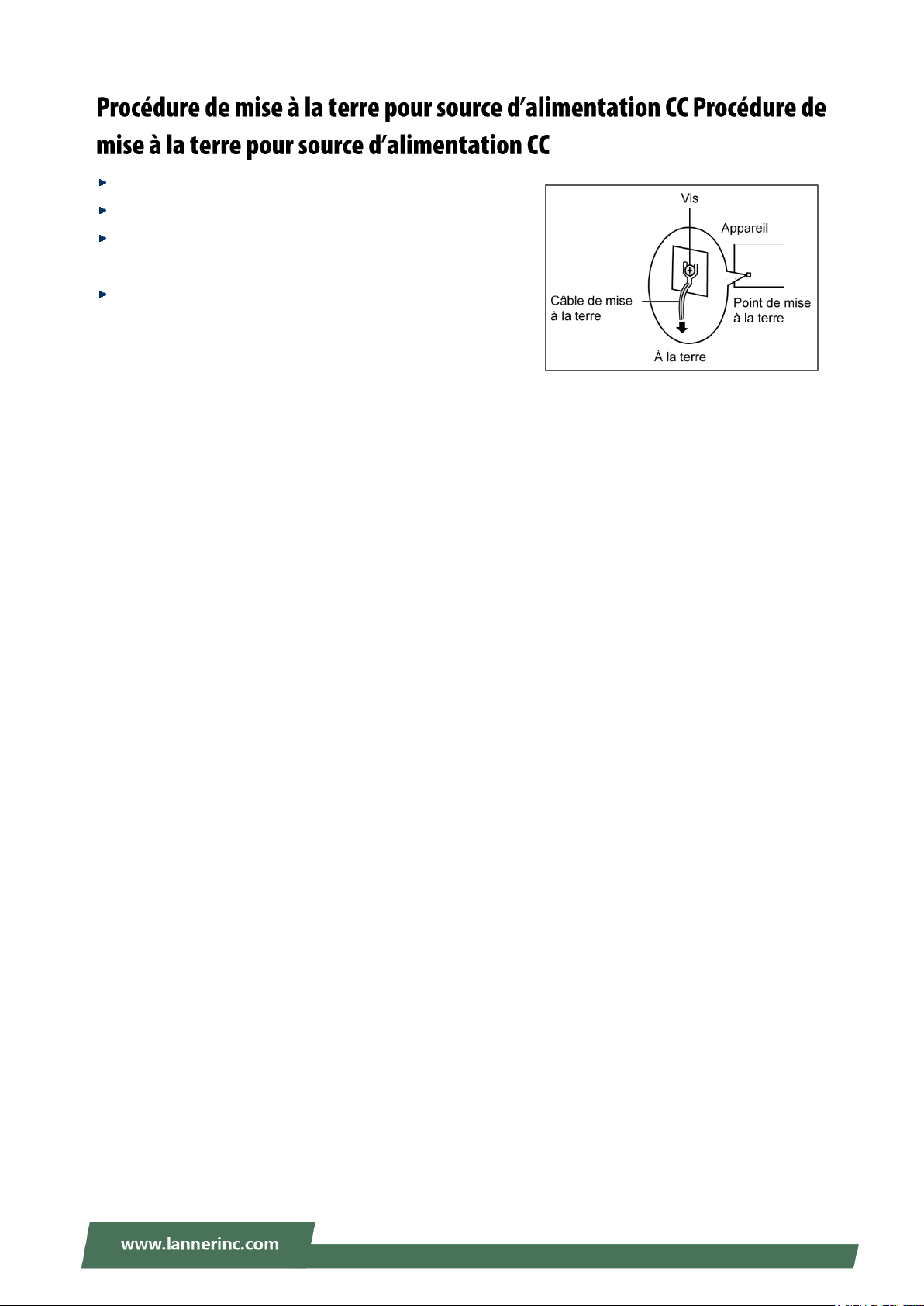
Avant d’allumer l’appareil, reliez le câble de mise à la terre de l’équipement à la terre.
Une bonne mise à la terre (connexion à la terre) est très importante pour protéger l’équipement contre
les effets néfastes du bruit externe et réduire les risques d’électrocution en cas de foudre.
Pour désinstaller l’équipement, débranchez le câble de mise à la terre après avoir éteint l’appareil.
Un câble de mise à la terre est requis et la zone reliant les sections du conducteur doit faire plus de 4
mm2 ou 10 AWG.
6
NCA-1020 User Manual
Desserrez la vis du terminal de mise à la terre.
Branchez le câble de mise à la terre à la terre.
L’appareil de protection pour la source d’alimentation CC
doit fournir 30 A de courant.
Cet appareil de protection doit être branché à la source
d’alimentation avant l’alimentation CC.
7

Version
Date
Descriptions
1.0
2017/07/18
1st Draft
1.1
2017/09/29
Modified ToC
1.2
2017/11/30
Modified Front Panel and Connector Pin Assignments
1.3
2018/01/03
Modified Chapter 3: Board Layout
1.4
2018/07/09
Modified System Specifications
1.5
2019/02/13
Add Rack mount Kit
1.6
2019/09/06
Update Specifications and BIOS Setup
8
NCA-1020 User Manual
Package Content ......................................................................................................................... 11
Ordering Information ................................................................................................................. 11
System Specifications ................................................................................................................. 12
Mechanical Drawing ................................................................................................................... 13
Block Diagram ............................................................................................................................. 15
Front Panel ................................................................................................................................. 16
Rear Panel ................................................................................................................................... 17
Jumpers and Connectors on the Motherboard .......................................................................... 18
Jumper Setting and Connector Pin-out ...................................................................................... 20
Preparing the Hardware Installation .......................................................................................... 25
Installing the System Memory .................................................................................................... 27
Installing Mini-PCIe Modules ...................................................................................................... 29
Installing Disk Drives ................................................................................................................... 30
Installing SMA Antenna (optional) ............................................................................................. 32
Rackmounting the System (with the Adapter Holder) ............................................................... 33
Main ............................................................................................................................................ 36
Advanced Page ........................................................................................................................... 38
Chipset Page ............................................................................................................................... 54
9
Security ....................................................................................................................................... 57
Boot Menu .................................................................................................................................. 60
Save and Exit Menu .................................................................................................................... 61
For Parallel Text-based LCM ....................................................................................................... 65
Warranty Policy .......................................................................................................................... 69
RMA Service ................................................................................................................................ 69
RMA Service Request Form ........................................................................................................ 70
10
NCA-1020 User Manual
SKU No.
Main Features
NCA-1020A
Ultra Compact Fanless x86 Network Appliance with Intel Braswell N3010 2C 1.04GHz, 1x
DDR3L SO-DIMM slot, 3x Gbe RJ45(3x Intel I211) with 1 pair bypass, USB, Console,
HDMI, support 1x SSD
NCA-1020B
Ultra Compact Fanless x86 Network Appliance with Intel Braswell N3010 2C 1.04GHz, 1x
DDR3L SO-DIMM slot, 3x Gbe RJ45(3x Intel I211), with 1 pair bypass, USB, Console,
HDMI
Thank you for choosing NCA-1020. Lanner’s NCA-1020 is a compact desktop appliance empowered by
Intel® Celeron® Processor N3010 (code-named Braswell) for deployment at edge environment, branch
offices, and retail surroundings. Besides the low power consumption and decent processing
capability, NCA-1020 also provides necessary I/O functionality for edge computing, multi-service gateways,
VPN routers and CPE applications.
Here is the summary of the key features:
Intel® Celeron® N3010 CPU
1x 204-pin DIMM DDR3L 1600 MHz non-ECC up to 8GB
Ultra-compact design for edge computing, multi-service gateways, SME VPN routers and CPE
applications
3x RJ45 GbE LAN ports
1x pair of LAN Bypass
Built-in with AES-NI crypto-security
Fanless design
2x SMA antenna holes
1x SATA 2.5” SSD tray (By SKU)
1x HDMI port
1x RJ-45 console port
Your package contains the following items:
1x NCA-1020 Network Appliance
1x 36W Power adaptor
1x U.S standard Power cord
Note: If any component should be missing or damaged, please contact your dealer immediately
for assistance.
11
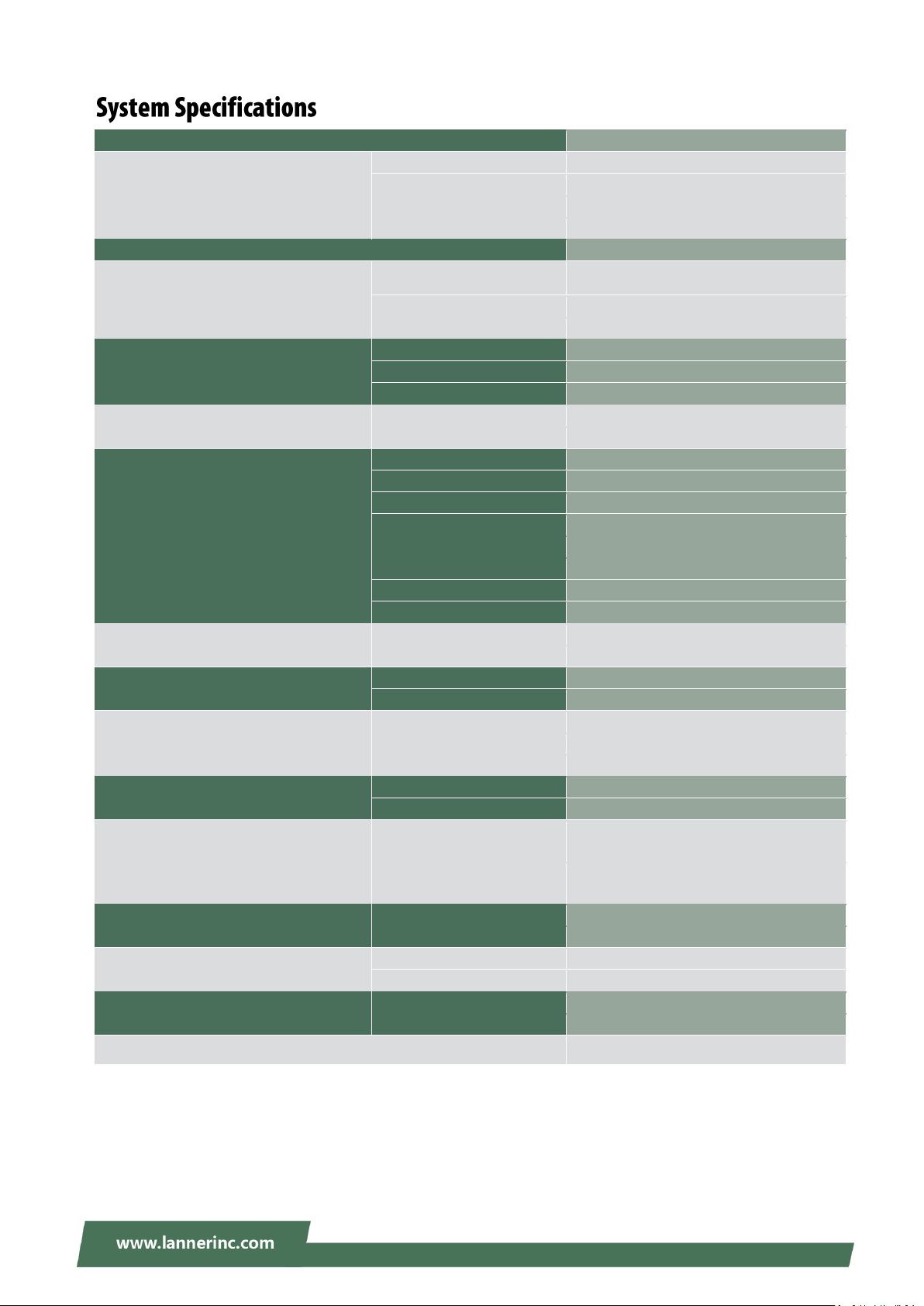
Chapter 1: Product Overview
Form Factor
Fanless Desktop
Platform
Processor Options
Intel® Celeron® N3010 (Braswell)
CPU Socket
Onboard
Chipset
SoC
Security Acceleration
N/A
BIOS
AMI SPI Flash BIOS
System Memory
Technology
DDR3L 1600MHz UDIMM
Max. Capacity
8 GB
Socket
1 x 204pin SODIMM
Networking
Ethernet Ports
3 x GbE RJ45 Intel® i211
Bypass
1 pair Gen2
NIC Module Slot
N/A
LOM
IO Interface
N/A
OPMA slot
N/A
I/O Interface
Reset Button
1
LED
Power LED on Power Button
Power Button
1
Console
1 x RJ45
USB
1 x USB 2.0, 1 x USB 3.0
LCD Module
N/A
Display
1 x HDMI
Power input
1 x DC Jack
Storage
HDD/SSD Support
1 x 2.5" Bay - SSD Only (By SKU)
Onboard Slots
1 x mSATA mini
Expansion
PCIe
N/A
mini-PCIe
1 x Mini-PCIe (PCIe/USB2.0)
Miscellaneous
Watchdog
YES
Internal RTC with Li Battery
YES
TPM
YES (Optional)
Cooling
Processor
Passive CPU Heatsink
System
Fanless
Environmental Parameters
Temperature
0~40ºC Operating
-20~70ºC Non-Operating
Humidity (RH)
5~90% Operating
5~ 95% Non-Operating
System Dimensions
(WxDxH)
137 x 36 x 120 mm
Weight
0.5 kg
Package Dimensions
(WxDxH)
426 x 252 x 282 mm
Weight
8.5 kg (10 in 1)
Power
Type/Watts
12V 3A 36W Power Adapter
Input
AC 100~240V @50~60 Hz
Approvals and Compliance
RoHS, CE, FCC Class B
12
NCA-1020 User Manual
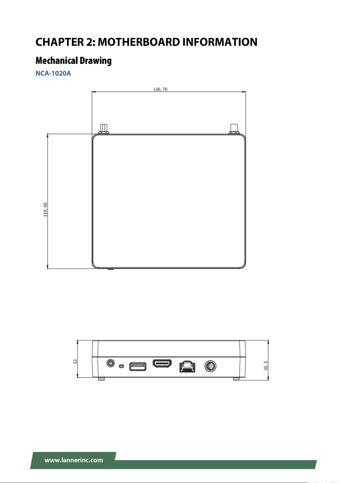
Unit: mm
13
Chapter 2: Motherboard Information
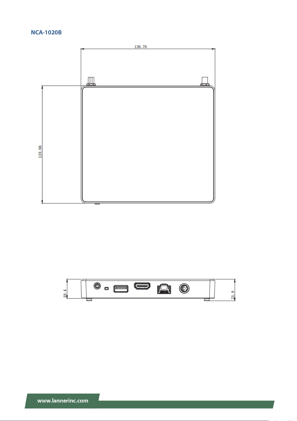
Unit: mm
14
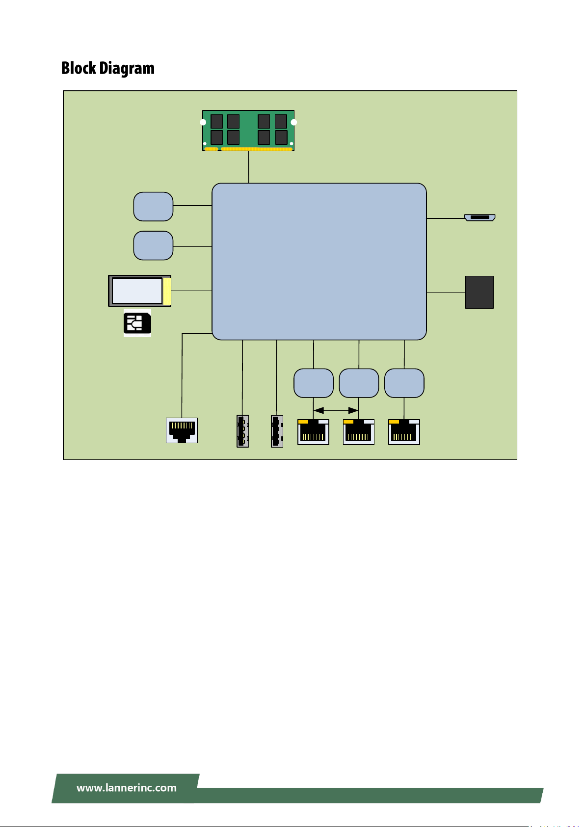
NCA-1020 User Manual
Braswell 2C
Up to 4W
i211 i211 i211
PCIe x1
USB 3.0
PCIe x1 PCIe x1
PCIe x1
USB 2.0
USB 3.0
EMMC
5.0
Mini PCI-E
DDR3
DDR3L Non-ECC 1600MHz
SO-DIMM (204P) up to 8GB
UART
SPI
TPM
NCA-1020
HDMI
SIM
Bypass
15
Chapter 2: Motherboard Information
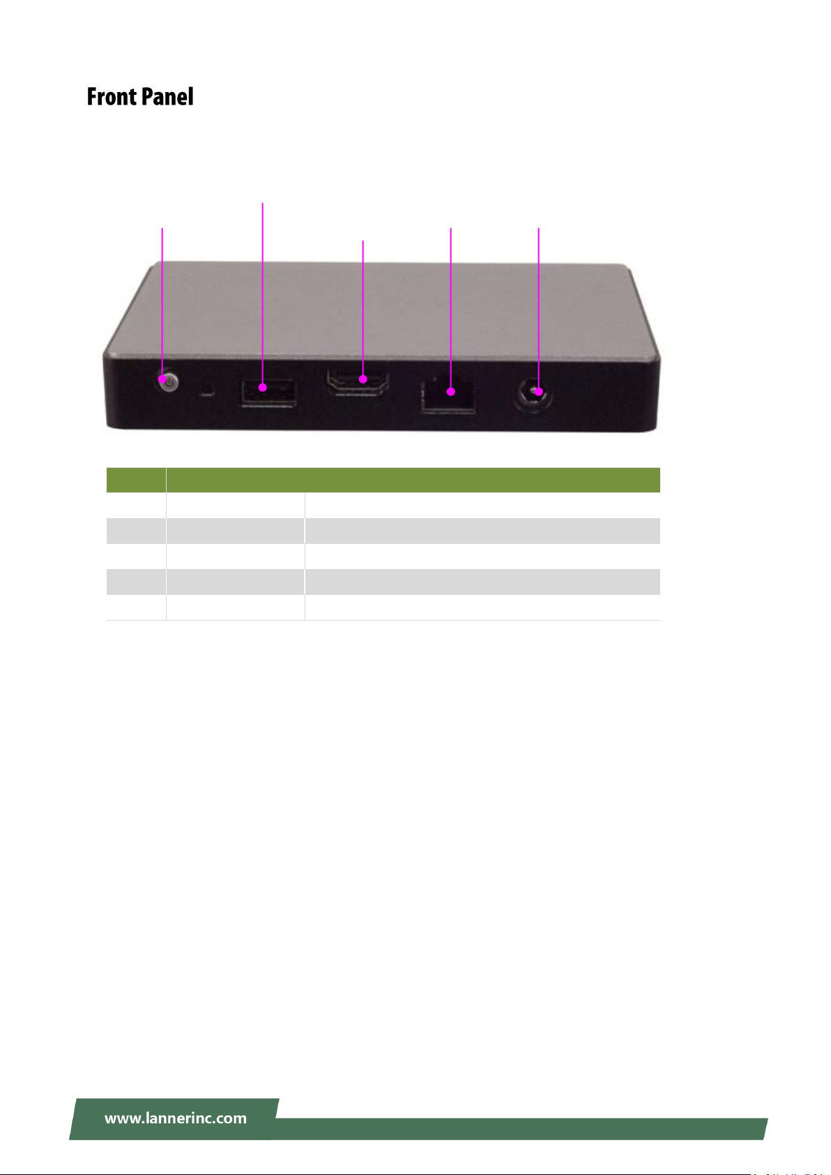
No.
Description
F1
Power
1 x Power on/off switch
F2
USB
1 x USB 2.0 Type-A port
F3
HDMI
1 x HDMI display port
F4
Console
1 x RJ-45 console port
F5
DC Power Jack
1 x DC power jack
F1
F2
F3
F4
F5
16
NCA-1020 User Manual
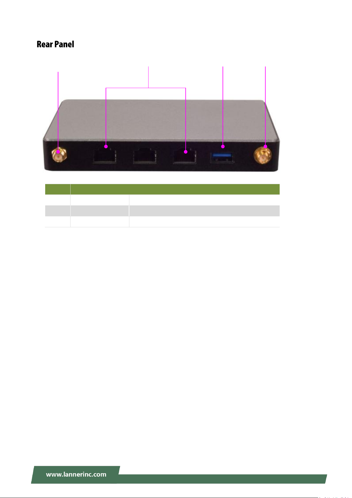
No.
Description
R1
Antenna
2 x SMA antenna holes
R2
LAN
3 x RJ-45 LAN ports (1 pair of bypass)
R3
USB
1 x USB 3.0 Type-A port
R2
R1
R3
R1
17
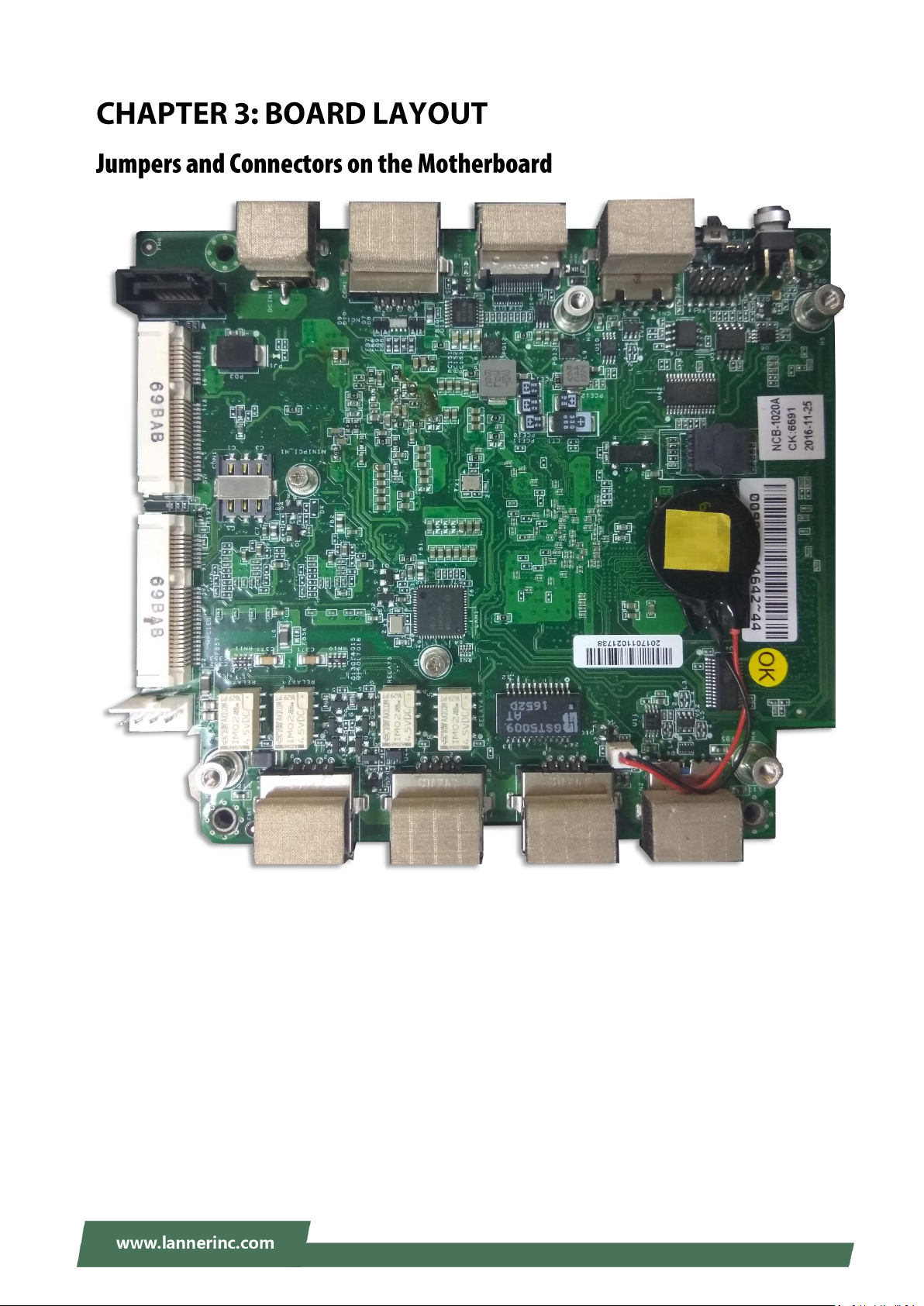
Chapter 3: Board Layout
C
C
C
N
N
N
1
1
1
C
C
C
N
N
N
2
2
2
R
R
R
J
J
J
3
3
3
R
R
R
J
J
J
2
2
2
R
R
R
J
J
J
1
1
1
H
H
H
D
D
D
M
M
M
I
I
I
C
C
C
O
O
O
M
M
M
1
1
1
M
M
M
P
P
P
C
C
C
I
I
I
E
E
E
2
2
2
M
M
M
P
P
P
C
C
C
I
I
I
E
E
E
1
1
1
C
C
C
O
O
O
N
N
N
1
1
1
S
S
S
A
A
A
T
T
T
A
A
A
1
1
1
P
P
P
S
S
S
4
4
4
P
P
P
1
1
1
J
J
J
2
2
2
0
0
0
L
L
L
P
P
P
C
C
C
1
1
1
J
J
J
7
7
7
18
NCA-1020 User Manual
D
D
D
I
I
I
M
M
M
M
M
M
19
Chapter 3: Board Layout
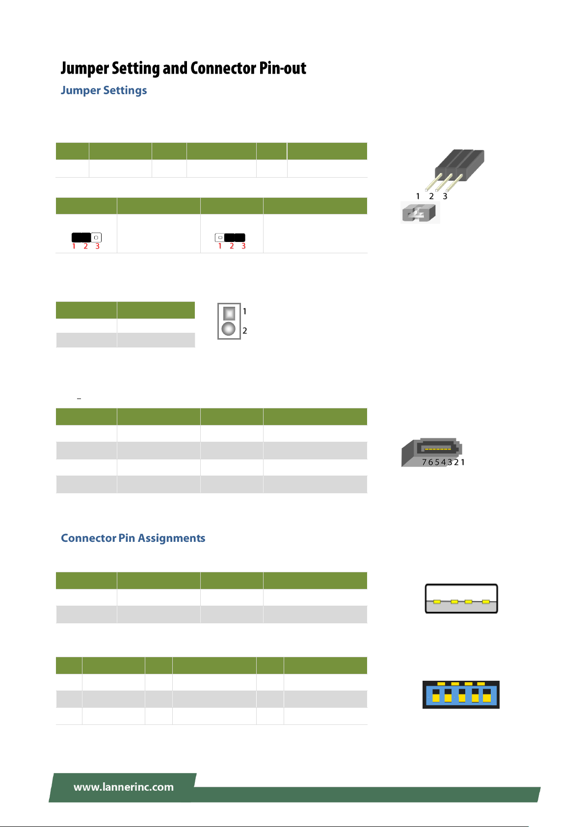
Pin
Description
Pin
Description
Pin
Description
1
HR_RST
2
BTN_RST_N1
3
SW_GPIO
Pin
Description
Pin
Description
1.2
HW reset
(Default)
2.3
SW reset
Pin
Description
1
BAT_D
2
GND
Pin
Description
Pin
Description
1
GND 2 TX+
3
TX- 4 GND
5
RX- 6 RX+
7
GND
Pin
Description
Pin
Description
1
VCC 5V 2 D-
3
D+ 4 GND
Pin
Description
Pin
Description
1
VCC 5V 2 D- 3 D+
4
GND
5
USB3_RX-
6
USB3_RX+
7
GND
8
USB3_TX-
9
USB3_TX+
5 6 7 8 9
4 3 2 1
4 3 2 1
J20: set the Reset Mode as Hardware (HW) Reset or Software (SW) Reset. Default “short pins” are 2-3 as
Software Reset (1x3-pin 2.54mm 3P DIP).
J7: Battery Pin Header
SATA1: SATA Port, SMD Type
180° SATA Connector
CN1: USB 2.0 Type-A ports in single form factor
CN2: USB3.0 CONN
COM1: RJ-45 console port for serial console
20
NCA-1020 User Manual
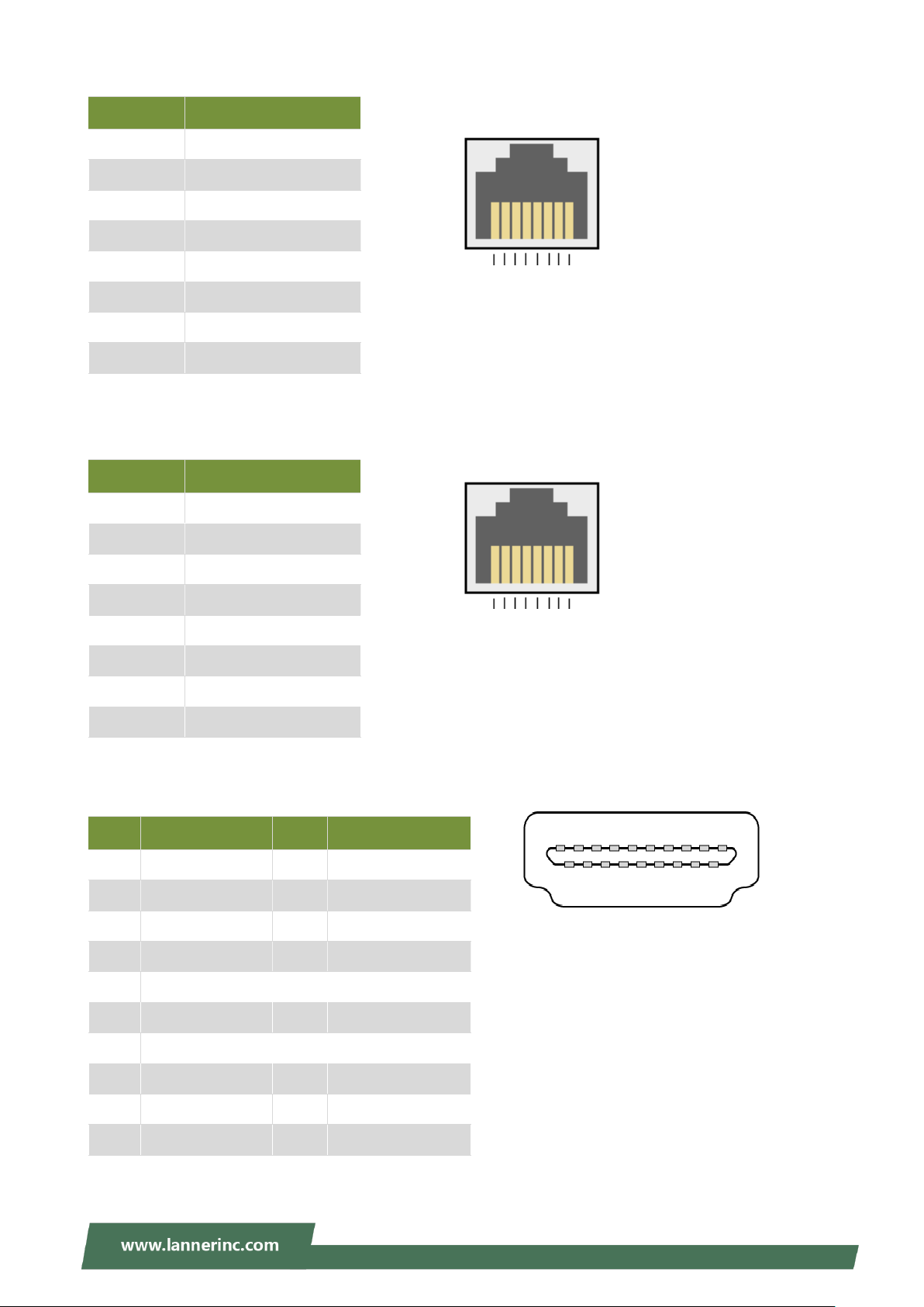
Pin
Description
1
NC 2 NC
3
Transmitted Data (TxD)
4
GND
5
GND
6
Received Data (RxD)
7
NC 8 NC
Pin
Description
1
MDI0+
2
MDI0-
3
MDI1+
4
MDI2+
5
MDI2-
6
MDI1-
7
MDI3+
8
MDI3-
Pin
Description
Pin
Description
1
DATA+
2
GND
3
DATA2-
4
DATA1+
5
GND
6
DATA1-
7
DATA0+
8
GND
9
DATA0-
10
CLK+
11
GND
12
CLK-
13
NC
14
NC
15
SCL
16
SDA
17
GND
18
GND
19
HOT_PLUG_DET
8 7 6 5 4 3 2 1
8 7 6 5 4 3 2 1
19 17 15 13 11 9 7 5 3 1
18 16 14 12 10 8 6 4 2
RJ1/2/3: RJ45 LAN Connectors
HDMI: HDMI Connector
PS4P1: 4-pin SATA power connector at 2.54mm for SATA storage device
21
 Loading...