

Page 1

NCA-1010
User Manual
Version: 1.5
Date of Release: 2019/03/22
Network
Computing
Page 2
NCA-1010 User Manual
Resources
URL
Lanner
http://www.lannerinc.com
Product Resource
http://www.lannerinc.com/download-center
RMA
http://eRMA.lannerinc.com
The icons are used in the manual to serve as an indication of interest topics or important messages. Below
is a description of these icons:
Note: This check mark indicates that there is a note of interest and is something that you should
pay special attention to while using the product.
Warning: This exclamation point indicates that there is a caution or warning and it is something
that could damage your property or product.
The listed websites are links to the on-line product information and technical support.
This document is copyrighted, © 2019 All rights are reserved. The original manufacturer reserves the right
to make improvements to the products described in this manual at any time without notice.
No part of this manual may be reproduced, copied, translated or transmitted in any form or by any means
without the prior written permission of the original manufacturer. Information provided in this manual is
intended to be accurate and reliable. However, the original manufacturer assumes no responsibility for its
use, nor for any infringements upon the rights of third parties that may result from such use.
Intel, Pentium and Celeron are registered trademarks of Intel Corp.
Microsoft Windows and MS-DOS are registered trademarks of Microsoft Corp.
All other product names or trademarks are properties of their respective owners.
2
Page 3
This product has passed the CE test for environmental specifications. Test conditions for passing included
the equipment being operated within an industrial enclosure. In order to protect the product from being
damaged by ESD (Electrostatic Discharge) and EMI leakage, we strongly recommend the use of
CE-compliant industrial enclosure products.
This equipment has been tested and found to comply with the limits for a Class B digital device.
This equipment has been tested and found to comply with the limits for a Class A digital device, pursuant to
Part 15 of the FCC Rules. These limits are designed to provide reasonable protection against harmful
interference when the equipment is operated in a commercial environment. This equipment generates,
uses, and can radiate radio frequency energy and, if not installed and used in accordance with the
instruction manual, may cause harmful interference to radio communications. Operation of this equipment
in a residential area is likely to cause harmful interference in which case users will be required to correct the
interference at their own expense.
Follow these guidelines to ensure general safety:
Keep the chassis area clear and dust-free during and after installation.
Do not wear loose clothing or jewelry that could get caught in the chassis. Fasten your tie or scarf
and roll up your sleeves.
Wear safety glasses if you are working under any conditions that might be hazardous to your
eyes.
Do not perform any action that creates a potential hazard to people or makes the equipment
unsafe.
Disconnect all power by turning off the power and unplugging the power cord before installing
or removing a chassis or working near power supplies
Do not work alone if potentially hazardous conditions exist.
Never assume that power is disconnected from a circuit; always check the circuit.
3
Page 4
NCA-1010 User Manual
Risk of Explosion if Battery is replaced by an incorrect type. Dispose of used batteries according to the
instructions.
Installation only by a trained electrician or only by an electrically trained person who knows all
English Installation and Device Specifications which are to be applied.
Do not carry the handle of power supplies when moving to another place.
The machine can only be used in a fixed location such as labs or computer facilities.
Electrical equipment generates heat. Ambient air temperature may not be adequate to cool
equipment to acceptable operating temperatures without adequate circulation. Be sure that the
room in which you choose to operate your system has adequate air circulation.
Ensure that the chassis cover is secure. The chassis design allows cooling air to circulate
effectively. An open chassis permits air leaks, which may interrupt and redirect the flow of cooling
air from internal components.
Electrostatic discharge (ESD) can damage equipment and impair electrical circuitry. ESD damage
occurs when electronic components are improperly handled and can result in complete or
intermittent failures. Be sure to follow ESD-prevention procedures when removing and replacing
components to avoid these problems.
Wear an ESD-preventive wrist strap, ensuring that it makes good skin contact. If no wrist strap is
available, ground yourself by touching the metal part of the chassis.
Periodically check the resistance value of the antistatic strap, which should be between 1 and 10
megohms (Mohms).
Suivez ces consignes pour assurer la sécurité générale :
Laissez la zone du châssis propre et sans poussière pendant et après l’installation.
Ne portez pas de vêtements amples ou de bijoux qui pourraient être pris dans le châssis.
Attachez votre cravate ou écharpe et remontez vos manches.
Portez des lunettes de sécurité pour protéger vos yeux.
N’effectuez aucune action qui pourrait créer un danger pour d’autres ou rendre l’équipement
dangereux.
Coupez complètement l’alimentation en éteignant l’alimentation et en débranchant le cordon
d’alimentation avant d’installer ou de retirer un châssis ou de travailler à proximité de sources
d’alimentation.
Ne travaillez pas seul si des conditions dangereuses sont présentes.
Ne considérez jamais que l’alimentation est coupée d’un circuit, vérifiez toujours le circuit. Cet
appareil génère, utilise et émet une énergie radiofréquence et, s’il n’est pas installé et utilisé
4
Page 5
conformément aux instructions des fournisseurs de composants sans fil, il risque de provoquer
des interférences dans les communications radio.
Risque d’explosion si la pile est remplacée par une autre d’un mauvais type.
Jetez les piles usagées conformément aux instructions.
L’installation doit être effectuée par un électricien formé ou une personne formée à l’électricité
connaissant toutes les spécifications d’installation et d’appareil du produit.
Ne transportez pas l’unité en la tenant par le câble d’alimentation lorsque vous déplacez
l’appareil.
La machine ne peut être utilisée qu’à un lieu fixe comme en laboratoire, salle d’ordinateurs ou
salle de classe.
L’équipement électrique génère de la chaleur. La température ambiante peut ne pas être
adéquate pour refroidir l’équipement à une température de fonctionnement acceptable sans
circulation adaptée. Vérifiez que votre site propose une circulation d’air adéquate.
Vérifiez que le couvercle du châssis est bien fixé. La conception du châssis permet à l’air de
refroidissement de bien circuler. Un châssis ouvert laisse l’air s’échapper, ce qui peut interrompre
et rediriger le flux d’air frais destiné aux composants internes.
Les décharges électrostatiques (ESD) peuvent endommager l’équipement et gêner les circuits
électriques. Des dégâts d’ESD surviennent lorsque des composants électroniques sont mal
manipulés et peuvent causer des pannes totales ou intermittentes. Suivez les procédures de
prévention d’ESD lors du retrait et du remplacement de composants.
Portez un bracelet anti-ESD et veillez à ce qu’il soit bien au contact de la peau. Si aucun bracelet
n’est disponible, reliez votre corps à la terre en touchant la partie métallique du châssis.
Vérifiez régulièrement la valeur de résistance du bracelet antistatique, qui doit être comprise
entre 1 et 10 mégohms (Mohms).
Avant d’allumer l’appareil, reliez le câble de mise à la terre de l’équipement à la terre.
Une bonne mise à la terre (connexion à la terre) est très importante pour protéger l’équipement
contre les effets néfastes du bruit externe et réduire les risques d’électrocution en cas de foudre.
Pour désinstaller l’équipement, débranchez le câble de mise à la terre après avoir éteint l’appareil.
Un câble de mise à la terre est requis et la zone reliant les sections du conducteur doit faire plus
de 4 mm2 ou 10 AWG.
5
Page 6
NCA-1010 User Manual
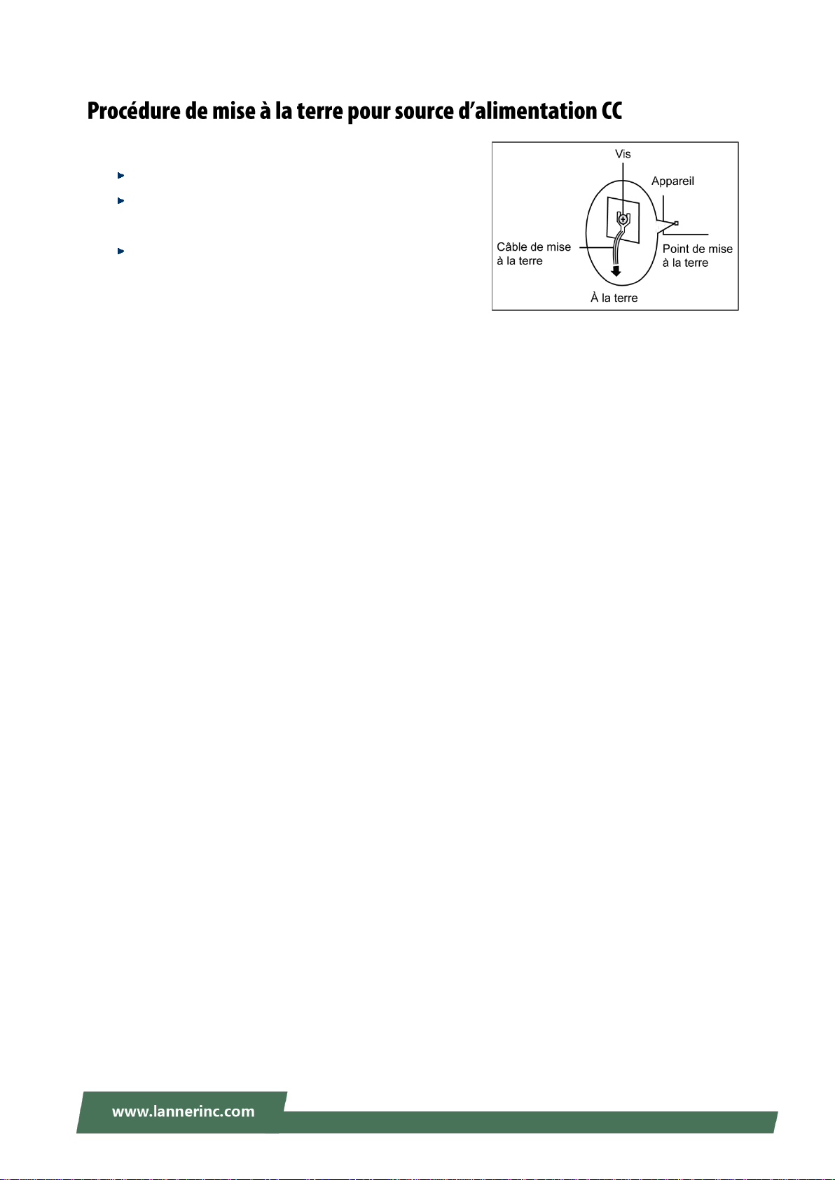
Desserrez la vis du terminal de mise à la terre.
Branchez le câble de mise à la terre à la terre.
L’appareil de protection pour la source
d’alimentation CC doit fournir 30 A de courant.
Cet appareil de protection doit être branché à la
source d’alimentation avant l’alimentation CC.
6
Page 7

Version
Date
Descriptions
0.1
2015/03/25
Preliminary
0.2
2015/05/18
Added Appendix
0.3
2015/05/25
Modified specifications
Added safety guidelines
0.4
2015/06/19
Modified power adapter information
0.5
2015/08/11
Modified reset button to “hardware reset only”
0.6
2015/08/31
Added pin assignments
1.0
2016/04/08
Official release
1.1
2016/06/02
Added reset jumper on motherboard due to changes in motherboard
design
1.2
2016/06/13
Modified console pin assignments
1.3
2016/10/14
Added notes for “No Restore AC Power Loss”
1.4
2016/11/10
Modified FCC from Class A to Class B
1.5
2019/03/22
Updated BIOS Setup
7
Page 8
NCA-1010 User Manual
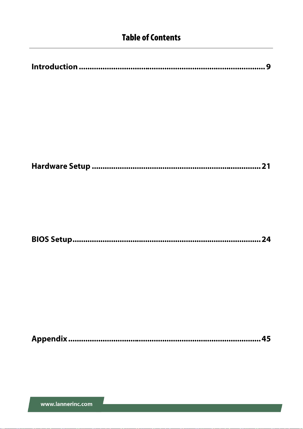
System Specifications ................................................................................................................. 10
Front Panel ................................................................................................................................. 12
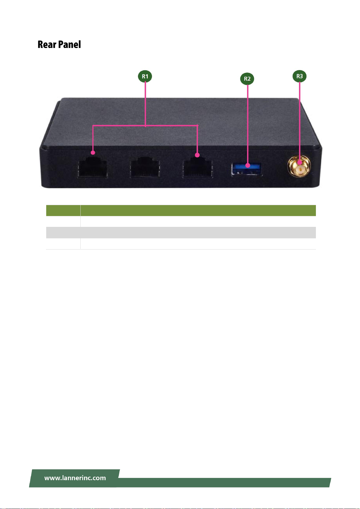
Rear Panel ................................................................................................................................... 13
Motherboard Layout .................................................................................................................. 14
Block Diagram ............................................................................................................................. 16
Internal Jumper & Connectors ................................................................................................... 17
Preparing the Hardware Installation .......................................................................................... 21
Installing the System Memory .................................................................................................... 21
Installing Mini PCIe Wireless Module ......................................................................................... 22
Installing mSATA Mini Module ................................................................................................... 23
Main Page ................................................................................................................................... 25
Advanced Page ........................................................................................................................... 26
Chipset ........................................................................................................................................ 37
Security ....................................................................................................................................... 41
Boot Menu .................................................................................................................................. 42
Save and Exit Menu .................................................................................................................... 43
Terms and Conditions ................................................................................................................. 45
8
Page 9

Introduction
Thank you for choosing Lanner's NCA-1010. This desktop platform is Lanner’s revolutionary ultra compact
x86 networking system built with Intel Bay Trail CPU (Atom™ E3815). The central processor comes with
hardware-assisted security mechanisms including AES-NI, Secure Boot and TPM, allowing only authorized
software or data to run on NCA-1010. With built-in instruction commands, NCA-1010 helps manage and
secure devices connected to local WiFi network, like a compact entry-level firewall or multi-service gateway.
Despite its compact size, NCA-1010 delivers rich I/O connectivity and scalability. In terms of scalability,
NCA-1010 comes with one HDMI port for high definition display, one console port for device network
management, three LAN ports for network connections, two USB ports (one in USB 2.0 and another in USB
3.0 specifications) for external devices, and one antenna hole for signal reception. The rich I/O connectivity
makes NCA-1010 a widely deployable system in small area network environments.
For scalability, the inside of NCA-1010 provides one full-length mini-PCIe socket for Wi-Fi/3G/LTE module
to bring wireless connectivity to the system. In addition, there is also a half-length mini-PCIe socket for
mSATA storage. This will allow NCA-1010 to serve as a local media server when connected wirelessly.
With the features discussed above, NCA-1010 is ideally applicable in multi-service gateway control, entry
firewall for SMEs, retail, library and hospital environments, as well as wireless network access and
bandwidth management in small area networks.
9
Page 10
NCA-1010 User Manual
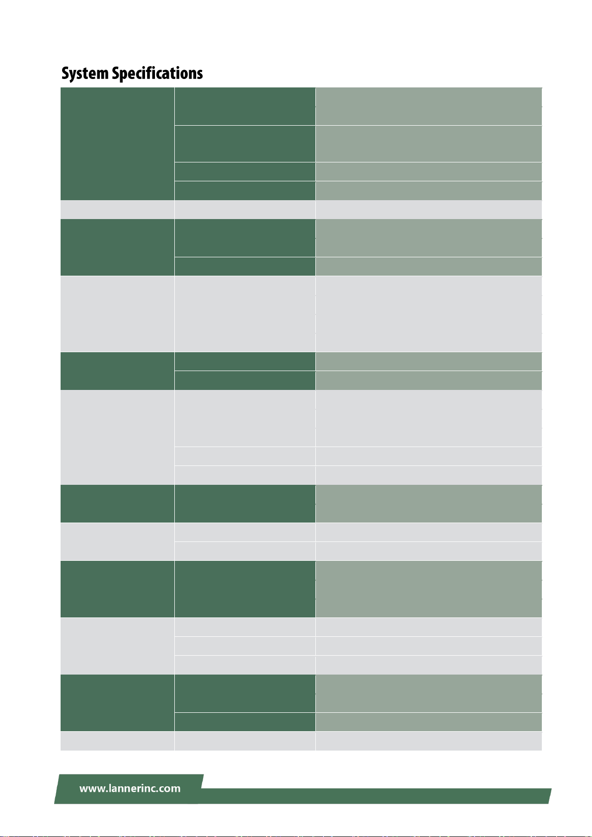
Processor System
CPU
Intel® Bay Trail E3815 or E3825 CPU
Frequency
1.46 GHz
Core Number
E3815 CPU: single core
E3825 CPU: dual cores
BIOS
AMI SPI Flash BIOS
Chipset
N/A
Thermal
Fanless
Yes
Memory
Technology
DDR3L 1067 MHz non-ECC
Max. Capacity
8GB
Socket
1 x 204-pin DIMM
Ethernet
Controller
3 x Intel i211
Speed
10/100/1000 Mbps
Interface
RJ-45
Bypass
N/A
Storage
Type
mSATA
Installation
1 x mSATA
I/O
Reset Button
1 x reset button (Hardware reset only)
Console
1 x RJ45
USB
USB 2.0 x 1, USB 3.0 x 1
IPMI
N/A
TPM
Optional
Expansion
PCIe
1 x mini-PCIe
PCI
N/A
Cooling
Processor
Passive CPU heatsink
System
Fanless
Environment
Operating Temperature
0 ~ 40ºC
Non-operating Temperature
-20 ~ 70ºC
Relative Humidity
0% ~ 90%, non-condensing
Miscellaneous
LCD Module
N/A
Watchdog
N/A
Internal RTC with Li Battery
Yes
Mechanical
Dimension (W x H x D)
124.26 x 19.4 x 119.66 mm
Weight
0.5 kg
Mounting
N/A
Power
Type / Watts
36W power adapter
10
Page 11

Introduction
Input*
AC 100~240V@50~60 Hz
Driver Support
Microsoft Windows
Windows 7, Windows 8, WES 7, WES 8
Linux
Linux (Fedora 18/Yocto)
Certification
EMC
CE Class B, FCC Class A, RoHS
Safety
UL
11
Page 12
NCA-1010 User Manual
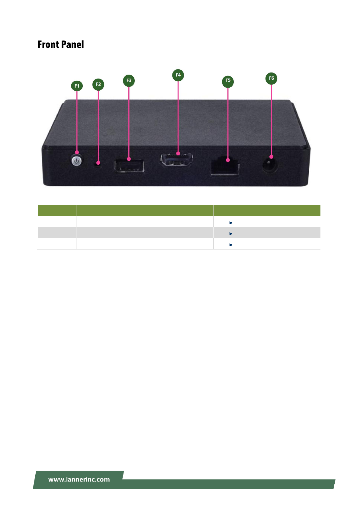
No.
Description
No.
Description
F1
Power switch
F2
Reset
F3
USB 2.0 port
F4
HDMI output port
F5
Console Port
F6
Power input
12
Page 13
Introduction
No.
Description
R1
3 x Ethernet LAN ports in RJ-45 connectors
R2
USB 3.0 port, backward compatible with USB 2.0
R3
Antenna hole
13
Page 14
NCA-1010 User Manual
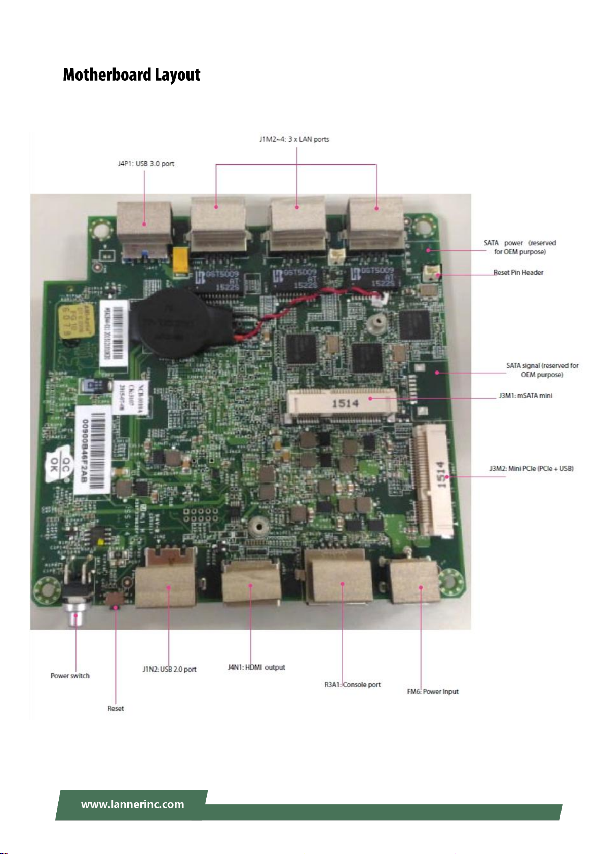
The motherboard layout shows the connectors and jumpers on the board. Refer to the following picture as
a reference of the pin assignments and the internal connectors.
14
Page 15

Introduction
15
Page 16

NCA-1010 User Manual
16
Page 17

Introduction
Pin
Signal
Pin
Signal
1
VCC 5V 2 D-
3
D+ 4 GND
Pin
Signal
Pin
Signal
1
VCC 5V
2
D- 3 D+ 4 GND
5
USB3_RX-
6
USB3_RX+
7
GND
8
USB3_TX-
9
USB3_TX+
Pin
Signal
Pin
Signal 1 N/A
2
NC
3
Transmitted Data (TxD)
4
GND 5 GND
6
Received Data (RxD)
7
NC
8
N/A
USB 2.0 port (J1N2):
USB 3.0 port (J4P1)
Console Port (J1M5):
The console port is defined in serial interface.
17
Page 18

NCA-1010 User Manual
Pin
Signal
Pin
Signal
Pin
Signal
Pin
Signal
1
NC 2 3.3V 3 NC 4 GND
5
NC 6 NC 7 NC 8 NC
9
GND
10
NC
11
NC
12
NC
13
NC
14
NC
15
GND
16
NC
17
NC
18
GND
19
NC
20
NC
21
GND
22
NC
23
RX+
24
3.3V
25
RX-
26
GND
27
GND
28
NC
29
GND
30
NC
31
TX-
32
NC
33
TX+
34
GND
35
GND
36
NC
37
GND
38
NC
39
3.3V
40
GND
41
3.3V
42
NC
43
GND
44
NC
45
NC
46
NC
47
NC
48
NC
49
NC
50
GND
51
NC
52
3.3V
mSATA socket (J3M1):
18
Page 19

Introduction
Pin
Signal
Pin
Signal
Pin
Signal
Pin
Signal
1
WAKE
2
3.3V 3 NC 4 GND
5
NC 6 1.5V
7
CLKREQ
8
NC
9
GND
10
NC
11
CLK-
12
NC
13
CLK+
14
NC
15
GND
16
NC
17
NC
18
GND
19
NC
20
NC
21
GND
22
RESET
23
PCIE_RX-
24
3.3V
25
PCIE_RX+
26
GND
27
GND
28
1.5V
29
GND
30
SMB_CLK
31
PCIE_TX-
32
SMB_DAT
33
PCIE_TX+
34
GND
35
GND
36
USB_D-
37
GND
38
USB_D+
39
3.3V
40
GND
41
3.3V
42
NC
43
GND
44
NC
45
NC
46
NC
47
NC
48
1.5V
49
NC
50
GND
51
NC
52
3.3V
Mini-PCI Express socket (J3M2):
LAN Ports ( J1M2/J1M3/J1M4)
19
Page 20

NCA-1010 User Manual
Pin
Signal
Pin
Signal
Pin
Signal
Pin
Signal
1
MDI0+
2
MDI0-
3
MDI1+
4
MDI2+
5
MDI2-
6
MDI1-
7
MDI3+
8
MDI3-
Pin
Signal
Pin
Signal
1
Reset 2 GND
Pin
Signal
Pin
Signal
1
DAT2+
2
GND
3
DATA2-
4
DATA1+
5
GND
6
DATA1-
7
DATA0+
8
GND
9
DATA0-
10
CLK+
11
GND
12
CLK-
13
NC
14
NC
15
SCL
16
SDA
17
GND
18
GND
19
HOT_PLUG_DET
Reset Pin Header
HDMI Display Port (J4N1):
20
Page 21

Hardware Setup
Locate the DIMM socket at the
bottom side of the motherboard.
Align the notches of both the socket
and the module.
Insert the module into the socket,
press the module and lock it with clips
on both sides.
Warning: (1) To reduce the risk of personal injury, electric shock, or damage to the equipment,
please remove all power sources. (2) Please wear ESD protected gloves before conducting the
following steps. (3) Do NOT pile items on top of the system to prevent damages due to this improper use.
Lanner is not liable for damages caused by improper use of the product.
The motherboard supports DDR3L non-ECC DIMM memory. Please follow the steps to install the DIMM
module.
21
Page 22

NCA-1010 User Manual
Locate the mini-PCIe socket and align
the notches between the socket and
the module. Then insert the module
as shown in the image.
Press the module down and lock it
with a screw, as demonstrated in the
image.
NCA-1010 motherboard is designed with a mini-PCIe wireless module socket. Please follow the steps below
for installation.
22
Page 23

Hardware Setup
Locate the mSATA Mini socket and
align the notches between the socket
and the module. Then insert the
module as shown in the image.
Press the module down and lock it
with a screw, as demonstrated in the
image.
NCA-1010 motherboard is designed with an mSATA Mini socket for storage purpose. Please follow the
steps below for installation.
23
Page 24

NCA-1010 User Manual
Control Keys
Description
select a setup screen
select an item/option on a setup screen
<Enter>
select an item/option or enter a sub-menu
+/-
adjust values for the selected setup item/option
F1
display General Help screen
F2
retrieve previous values, such as the last configured parameters during the last
time you entered BIOS
F3
load optimized default values
F4
save configurations and exit BIOS
<Esc>
exit the current screen
To enter the BIOS setup utility, simply follow the steps below:
1. Boot up the system.
2. Pressing the <Tab> or <Del> key immediately allows you to enter the Setup utility, then you will be
directed to the BIOS main screen. The instructions for BIOS navigations are as below:
*No "Restore AC Power Loss" option in NCA-1010 BIOS setting. The parameter is set as "Power On" by
default.
24
Page 25

Feature
Description
BIOS
Information
BIOS Vendor: American Megatrends
Core Version: AMI Kernel version, CRB code base, X64
Compliancy: UEFI version, PI version
Project Version: BIOS release version
Access Level: Administrator / User
Memory
Information
Total Memory: Total Memory size.
System
Language
English
System Date
To set the Date, use <Tab> to switch between Date elements.
Default Range of Year: 2005-2099
Default Range of Month: 1-12
Days: dependent on Month.
System Time
To set the Date, use <Tab> to switch between Date elements.
Setup main page contains BIOS information and project version information.
25
Page 26

NCA-1010 User Manual
Feature
Options
Description
PXE Function
Disabled
Enable LAN1
Enable LAN2
Enable LAN3
PXE Function
Select the Advanced menu item from the BIOS setup screen to enter the “Advanced” setup screen. Users
can select any of the items in the left frame of the screen.
26
Page 27

27
Page 28

NCA-1010 User Manual
Feature
Options
Description
COM0
Console
Redirection
Enabled
Disabled
Enables or disables Console Redirection
28
Page 29

Feature
Options
Description
Terminal Type
VT100
VT100+
VT-UTF8
ANSI
VT100: ASCII char set
VT100+:Extends VT100 to support color, function
keys, etc.
VT-UTF8:Uses UTF8 encoding to map Unicode
chars onto 1 or more bytes
ANSI: Extended ASCII char set
Bits per second
9600
19200
38400
57600
115200
Selects serial port transmission speed. The speed
must be matched on the other side. Long or noisy
lines may require lower speeds.
Data Bits
7
8
Data Bits
Parity
None
Even
Odd
Mark
Space
A parity bit can be sent with the data bits to detect
some transmission errors.
Stop Bits
1
2
Indicates the end of a serial data packet.
Flow Control
None
Hardware
RTS/CTS
Flow Control can prevent data loss from buffer
overflow.
VT-UTF8 Combo
Key Support
Disabled
Enabled
Enables VT-UTF8 Combination Key Support for
ANSI/VT100 terminals
Console Redirection Settings
29
Page 30

NCA-1010 User Manual
Recorder Mode
Disabled
Enabled
With this mode enabled, only text will be sent. This
is to capture Terminal data.
Resolution 100x31
Disabled
Enabled
Enables or disables extended terminal resolution
Legacy OS
Redirection
80x24
80x25
On Legacy OS, the Number of Rows and Columns
supported redirection.
Putty KeyPad
VT100
LINUX
XTERM86
SCO
ESCN
VT400
Selects FunctionKey and KeyPad on Putty.
Redirection After
BIOS POST
Always Enable
BootLoader
When Bootloader is selected, Legacy Console
Redirection is disabled before booting to legacy
OS. When Always Enable is selected, then Legacy
Console Redirection is enabled for legacy OS.
Default setting for this option is set to Always
Enable.
30
Page 31

Feature
Options
Description
Socket 0 CPU
Information
None
Socket specific CPU Information
Limit CPUID Maximum
Disabled
Enabled
Disabled for Windows XP
Execute Disable Bit
Disabled
Enabled
XD can prevent certain classes of malicious
buffer overflow attacks when combined
with a supporting OS (Windows Server
2003 SP1, Windows XP SP2, SuSE Linux 9.2,
RedHat Enterprise 3 Update 3.)
Hardware Prefetcher
Disabled
Enabled
Enable the Mid Level Cache (L2) streamer
prefetcher.
Adjacent Cache Line
Prefetch
Disabled
Enabled
Enable the Mid Level Cache (L2)
prefetching of adjacent cache lines.
Intel Virtualization
Disabled
Enabled
When enabled, a VMM can utilize the
additional hardware capabilities provided
by Vanderpool Technology
31
Page 32

NCA-1010 User Manual
Feature
Options
Description
Serial-ATA (SATA)
Disabled
Enabled
Enable / Disable Serial ATA
SATA Test Mode
Disabled
Enabled
Test Mode enable / disable.
SATA Speed Support
Gen1
Gen2
SATA Speed Support Gen1 or Gen2
SATA Mode
IDE Mode
AHCI Mode
Select IDE / AHCI
Serial-ATA Port 0
Disabled
Enabled
Enable / Disable Serial ATA Port 0
Serial-ATA Port 1
Disabled
Enabled
Enable / Disable Serial ATA Port 1
32
Page 33

Feature
Options
Description
Security Device
Support
Disabled
Enabled
Enables or disables BIOS support for
security device. By disabling this function,
OS will not show Security Device. TCG EFI
protocol and INT1A interface will not be
available.
33
Page 34

NCA-1010 User Manual
Feature
Options
Description
Security Device
Support
Disabled
Enabled
Enables or disables BIOS support for security device.
By disabling this function, OS will not show Security
Device. TCG EFI protocol and INT1A interface will not
be available.
TPM State
Enabled
Disabled
Enables or disables Security Device.
NOTE: Your computer will reboot during restart in
order to change State of the Device.
Pending
operation
None
TPM Clear
Schedules an Operation for the Security Device. NOTE:
Your computer will reboot during restart in order to
change State of Security Device.
Trusted Computing
34
Page 35

Feature
Options
Description
Legacy USB Support
Enabled
Disabled
Auto
Enables Legacy USB support.
Auto option disables legacy support if no
USB devices are connected;
Disabled option will keep USB devices
available only for EFI applications.
USB3.0 Support
Enabled
Disabled
Enable/Disable USB3.0 (XHCI) Controller
Support.
XHCI Hand-off
Enabled
Disabled
This is a workaround for OSes without
XHCI hand-off support. The XHCI
ownership change should be claimed by
XHCI driver.
EHCI Hand-off
Enabled
Disabled
This is a workaround for OSes without
EHCI hand-off support. The EHCI
ownership change should be claimed by
EHCI driver.
USB Mass Storage
Driver Support
Enabled
Disabled
Enables or disables USB Mass Storage
Driver Support.
USB transfer time-out
1 sec
5 sec
10 sec
20 sec
The time-out value for Control, Bulk, and
Interrupt transfers
Device reset time-out
1 sec
USB mass storage device Start Unit
35
Page 36

NCA-1010 User Manual
5 sec
10 sec
20 sec
command time-out
Device power-up delay
Auto
Manual
Maximum time the device will take before
it properly reports itself to the Host
Controller. Auto uses default value: for a
Root port, it is 100 ms, for a Hub port the
delay is taken from Hub descriptor.
36
Page 37

Select the Chipset menu item from the BIOS setup screen to enter the Platform Setup screen. Users can
select any of the items in the left frame of the screen.
37
Page 38

NCA-1010 User Manual
Feature
Options
Description
Max TOLUD.
Dynamic
1 GB
1.25 GB
1.5 GB
1.75 GB
2 GB
2.25 GB
2.5 GB
2.75 GB
3 GB
Maximum Value of TOLUD.
38
Page 39

Feature
Options
Description
High Precision
Timer
Enabled
Disabled
Enable or Disable the High Precision Event Timer.
39
Page 40

NCA-1010 User Manual
Feature
Options
Description
XHCI Mode
Enabled
Disabled
Auto
Mode of operation of xHCI controller
USB 2.0(EHCI)
Support
Disabled
Enabled
Control the USB EHCI (USB 2.0) functions. One EHCI
controller must always be enabled
USB Port 0
Disabled
Enabled
Enable / Disable USB Port 0
USB Port 2
Disabled
Enabled
Enable / Disable USB Port 2
USB Port 3
Disabled
Enabled
Enable / Disable USB Port 3
USB Configuration
40
Page 41

Feature
Description
Administrator Password
If ONLY the Administrator's password is set, it only
limits access to Setup and is only asked for when
entering Setup.
User Password
If ONLY the User's password is set, it serves as a
power-on password and must be entered to boot or
enter Setup. In Setup, the User will have Administrator
rights.
Select the Security menu item from the BIOS setup screen to enter the Security Setup screen. Users can
select any of the items in the left frame of the screen.
41
Page 42

NCA-1010 User Manual
Feature
Options
Description
Setup Prompt Timeout
1
The number of seconds to wait for setup
activation key.
65535 means indefinite waiting.
Bootup NumLock State
On
Off
Select the keyboard NumLock state
Quiet Boot
Disabled
Enabled
Enables or disables Quiet Boot option.
Fast Boot
Disabled
Enabled
Enables or disables boot with
initialization of a minimal set of devices
required to launch active boot option.
Has no effect for BBS boot options.
Select the Boot menu item from the BIOS setup screen to enter the Boot Setup screen. Users can select any
of the items in the left frame of the screen.
Choose boot priority from boot option priorities.
42
Page 43

Select the Save and Exit menu item from the BIOS setup screen to enter the Save and Exit Setup screen.
Users can select any of the items in the left frame of the screen.
■ Discard Changes and Exit
Select this option to quit Setup without saving any modifications to the system configuration. The following window
will appear after the “Discard Changes and Exit” option is selected. Select “Yes” to Discard changes and Exit Setup.
■ Save Changes and Reset
When Users have completed the system configuration changes, select this option to save the changes and reset
from BIOS Setup in order for the new system configuration parameters to take effect. The following window will
appear after selecting the “Save Changes and Reset” option is selected. Select “Yes” to Save Changes and reset.
43
Page 44

NCA-1010 User Manual
■ Restore Defaults
Restore default values for all setup options. Select “Yes” to load Optimized defaults.
PS: The items under Boot Override were not same with image. It should depend on devices connect on
system.
44
Page 45

Appendix
All products are under warranty against defects in materials and workmanship for a period of one
year from the date of purchase.
The buyer will bear the return freight charges for goods returned for repair within the warranty
period; whereas the manufacturer will bear the after service freight charges for goods returned to
the user.
The buyer will pay for repair (for replaced components plus service time) and transportation
charges (both ways) for items after the expiration of the warranty period.
If the RMA Service Request Form does not meet the stated requirement as listed on “RMA
Service,” RMA goods will be returned at customer’s expense.
The following conditions are excluded from this warranty: Improper or inadequate maintenance
by the customer Unauthorized modification, misuse, or reversed engineering of the product
Operation outside of the environmental specifications for the product.
Requesting a RMA#
To obtain a RMA number, simply fill out and fax the “RMA Request Form” to your supplier.
The customer is required to fill out the problem code as listed. If your problem is not among the
codes listed, please write the symptom description in the remarks box.
Ship the defective unit(s) on freight prepaid terms. Use the original packing materials when
possible.
Mark the RMA# clearly on the box.
Note: Customer is responsible for shipping damage(s) resulting from inadequate/loose packing
of the defective unit(s). All RMA# are valid for 30 days only; RMA goods received after the
effective RMA# period will be rejected.
45
Page 46

NCA-1010 User Manual
46
 Loading...