

Page 1

In-Vehicle Computing
Hardware Platforms for mobile applications
LVC-5570
V1.3
>>
User's Manual
Publication date:2014-07-02
Page 2
About
About
Overview
Icon Descriptions
The icons are used in the manual to serve as an indication
of interest topics or important messages. Below is a
description of these icons:
NOTE: This check mark indicates that
there is a note of interest and is something
that you should pay special attention to
while using the product.
Online Resources
The listed websites are links to the on-line product
information and technical support.
Resource Website
Lanner http://www.lannerinc.com
Product Resources
RMA http://eRMA.lannerinc.com
WARNING: This exclamation point
indicates that there is a caution or
warning and it is something that could
damage your property or product.
http://www.lannerinc.com/
support/download-center
Acknowledgement
Intel, Pentium and Celeron are registered trademarks of
Intel Corp.
Microsoft Windows and MS-DOS are registered trademarks
of Microsoft Corp.
All other product names or trademarks are properties of
their respective owners.
Compliances and Certification
CE Certication
This product has passed the CE test for environmental
specifications. Test conditions for passing included the
equipment being operated within an industrial enclosure.
In order to protect the product from being damaged by
ESD (Electrostatic Discharge) and EMI leakage, we strongly
recommend the use of CE-compliant industrial enclosure
products.
FCC Class A Certication
This equipment has been tested and found to comply
with the limits for a Class A digital device, pursuant to Part
15 of the FCC Rules. These limits are designed to provide
reasonable protection against harmful interference when
the equipment is operated in a commercial environment.
This equipment generates, uses and can radiate radio
frequency energy and, if not installed and used in
accordance with the instruction manual, may cause
harmful interference to radio communications. Operation
of this equipment in a residential area is likely to cause
harmful interference in which case the user will be required
to correct the interference at his own expense.
e Mark Certication
E13 - Luxembourg
Copyright and Trademarks
This document is copyrighted, © 2014. All rights are
reserved. The original manufacturer reserves the right to
make improvements to the products described in this
manual at any time without notice.
No part of this manual may be reproduced, copied,
translated or transmitted in any form or by any means
without the prior written permission of the original
manufacturer. Information provided in this manual is
intended to be accurate and reliable. However, the original
manufacturer assumes no responsibility for its use, nor for
any infringements upon the rights of third parties that
may result from such use.
Embedded and Industrial Computing
2
Page 3
About
About
Mechanical compliance
Vibration:
General Vibration (operating): Refer to MIL-STD-810G, •
Method 514.6, Procedure I (Transportation), Category
4 – Common carrier (US highway truck vibration
exposure)
General Vibration (non-operating): Refer to MIL-STD- •
810G, Method 514.6, Procedure I (Transportation),
Category 24 – General minimal integrity
Shock:
Operating (Functional Test for Ground Equipment): •
Refer to MIL-STD-810G, Method 516.6, Procedure I,
40g, 11ms
B. Non-Operating (Crash Hazard Shock Test for Ground •
Equipment): Refer to MIL-STD-810G, Method 516.6,
Procedure V, 75g, 11ms
Electrical transient conduction along supply lines only
(12V/24V)
Revision History
Revision Revision Date Changes
1.1 20130806 DVI-D, maximum
resolution changes
from 75 to 60Hz
VGA, maximum resolution changes from
60 to 75Hz
1.2 20130924 Change HDDSL1
jumper settings
1.3 20140701 Change the default
BIOS values for DIO
Embedded and Industrial Computing
3
Page 4

TTaTTable of Contentsbeable of Contents
Chapter 1: Introduction 5
System Specication . . . . . . . . . . . . . . . . . . . . . . . . . . . . . . . . . . . . . . . . . . . 5
Package Contents . . . . . . . . . . . . . . . . . . . . . . . . . . . . . . . . . . . . . . . . . . . . . 6
Chapter 2: System Components 7
System Drawing . . . . . . . . . . . . . . . . . . . . . . . . . . . . . . . . . . . . . . . . . . . . . . 7
Block Diagram: The MainBoard . . . . . . . . . . . . . . . . . . . . . . . . . . . . . . . . . . . . . 8
Block Diagram: The Ignition Board. . . . . . . . . . . . . . . . . . . . . . . . . . . . . . . . . . . 9
Front Components. . . . . . . . . . . . . . . . . . . . . . . . . . . . . . . . . . . . . . . . . . . . .10
Rear Components . . . . . . . . . . . . . . . . . . . . . . . . . . . . . . . . . . . . . . . . . . . . .11
Chapter 3: Board Layout 13
Connectors . . . . . . . . . . . . . . . . . . . . . . . . . . . . . . . . . . . . . . . . . . . . . . . . .13
Ignition Board Connectors. . . . . . . . . . . . . . . . . . . . . . . . . . . . . . . . . . . . . . . .14
External Connectors. . . . . . . . . . . . . . . . . . . . . . . . . . . . . . . . . . . . . . . . . . . .15
Internal Connectors and Jumpers . . . . . . . . . . . . . . . . . . . . . . . . . . . . . . . . . . .16
Internal Connectors and Jumpers (backside) . . . . . . . . . . . . . . . . . . . . . . . . . . . .17
Connectors and Jumpers List . . . . . . . . . . . . . . . . . . . . . . . . . . . . . . . . . . . . . .18
Jumper Settings . . . . . . . . . . . . . . . . . . . . . . . . . . . . . . . . . . . . . . . . . . . . . .19
Chapter 4: The Flow Chart 28
Chapter 5: Hardware Setup 29
Preparing the Hardware Installation. . . . . . . . . . . . . . . . . . . . . . . . . . . . . . . . . .29
Installing the System Memory . . . . . . . . . . . . . . . . . . . . . . . . . . . . . . . . . . . . .29
Wireless Module Installation . . . . . . . . . . . . . . . . . . . . . . . . . . . . . . . . . . . . . .30
3G SIM Card Installation . . . . . . . . . . . . . . . . . . . . . . . . . . . . . . . . . . . . . . . . .30
External SIM Card Installation . . . . . . . . . . . . . . . . . . . . . . . . . . . . . . . . . . . . . .30
Installing the Hard Disk . . . . . . . . . . . . . . . . . . . . . . . . . . . . . . . . . . . . . . . . . .31
Connecting Power . . . . . . . . . . . . . . . . . . . . . . . . . . . . . . . . . . . . . . . . . . . . .31
Appendix A: Using the Ignition System Manager (ISM) 32
Appendix B: Digital Input/Output 33
Appendix C: Accessing the Digital Accelerometer Data from the LVC-5570 39
Appendix D: Accessing the GPS Data from the LVC-5570 41
Appendix E: Programming System Watchdog Timer of the LVC-5570 43
Appendix F: Terms and Conditions 47
Warranty Policy . . . . . . . . . . . . . . . . . . . . . . . . . . . . . . . . . . . . . . . . . . . .47
RMA Service . . . . . . . . . . . . . . . . . . . . . . . . . . . . . . . . . . . . . . . . . . . . . .47
4
Page 5
Chapter 1
Chapter 1:
Introduction
Introduction
Thank you for choosing the LVC-5570. The LVC-5570 is
an ultra-robust embedded system which equips with
a suspension kit to eliminate shock and vibration. It is
designed to be installed on a moving transportation
system.
The system encompasses a wide variety of communication
ports to facilitate every possible in-vehicle applications
including surveillance, event data recorder and the GPS
receiver. It also features an external HDD drive bay for
easy insertion of the HDD/SSD. There is even an optional
audio port for voice communication through 3G wireless
service. The following list highlights the capabilities of
the LVC-5570 system:
One Digital I/O port for 4 digital input and 3 output •
connections (via a DE-15 connector).
Two additional pins from the above Digital I/O can •
be used for system wake-up to power on the system
automatically.
3G audio (optional) and PC audio ports •
Rich I/O ports: 2 RS-232/422/485, 2 LAN ports, 6USB •
ports (6 type A)
Triple Mini-PCIe connectors for 3G Internet services •
(with 3 SIM card readers for 3G wireless Internet
connections) and an additional PCIe expansion
suitable for Wi-Fi connection.
Dual video display: DVI-D+VGA or HDMI+VGA output •
with Intel® HD Graphics 3000
Power ignition control mechanism with programmable •
on/off/delay switch
Wide range of DC power input from 9V to 36V, suitable •
for vehicular 12V or 24V battery with Ignition control.
–Power input current protection by the 10A fuse and
15KP30A TVS
--12V DC output current protection by the 1A Polyfuse
Battery voltage protection: Over Voltage Protection •
and Under Voltage Protection
Standby power consumption are well under 12V/81mA
and 24V/83mA
Extended operating temperature between -20 ~ 55 ºC •
(-4 ~ 131ºF)
System Specification
Dimensions (WxHxD)
Processor Intel Core i7-2655LE Processors
Chipset Intel HM65
System
Memory
Ethernet Controller Intel 82574Lx2
Graphic Controller Intel integrated HD graphic engine
Audio Controller ALC886
IO
Power Input
AC Adapter Ordering Option
OS Support
Certications CE, FCC Class A, E13, RoHS
Compliance
Technology DDR3 SO-DIMMx2
Max. Capacity Up to 16GB
SATA
LAN GbE RJ45 x2
Display
Audio
Serial I/O 2xRS-232/422/485 with RI/5V/12V
GPIO
GPS Ublox NEO-6Q GPS receiver module
G-sensor ADXL 345
USB 2.0 Type A x6
Power Input 3-pin terminal block (+, -, ignition)
Expansion Mini-PCIex4 with 3 SIM card readers
Others
308x85.26x162mm
(12.13”x3.36”x6.38”)
Removable 2.5” SSD/HDD drive
bayx2, on-board 8GB SSD
DVI-D, maximum resolution up to
1920x1200@60Hz
VGA, maximum resolution up to
2048x1536@75Hz
HDMI, maximum resolution up to
1920x1200@60Hz
1x Mic-in and Line-out (for PC)
1x Mic-in and Line-out (for validated
Sierra MC-8090/8092 3G module)
via D-sub9
4x DI 12V TTL level
3x DO 12V TTL level
2x DI (for MCU) 5V TTL Level
External: 5x SMA antenna hole,
reset, Remote Power switch
9~36Vdc (max. 10A) output software On/Off
+9~36VDC input range, ATX mode
support ignition delay on/off
control
Linux Kernel 2.6.18 or later
Windows XPE/WES2009, XP Pro
FES, WS7E, Win 7 Pro FES
Vibration: MIL-STD-810G, Method
514.6 with SSD and suspension kit
Shock: MIL-STD-810G, Method
516.6 with SSD and suspension kit
Embedded and Industrial Computing
5
Page 6

Chapter 1
Introduction
Operating
Temperature
Range
Extended
Standard
With Industrial Components
-20~55°C/-4~131°F
With Commercial Components
-5~45°C / 23~113°F
Package Contents
Your package contains the following items:
LVC-5570 Fanless Embedded System with a suspension •
kit
Terminal Block Connectors •
(P/N: 04AW20031E001 3pin
04AW20043E101 4pin)
HDD Screws x 4 (P/N: 070W103000601) •
Mini-PCIe screw x8 (P/N: 070W101000401) •
3G audio cable x1 (P/N:080W120900503) •
Driver and User Manual CD x1 (P/N:S09OADA42H100) •
Embedded and Industrial Computing
6
Page 7
Chapter 2
Chapter 2:
System Components
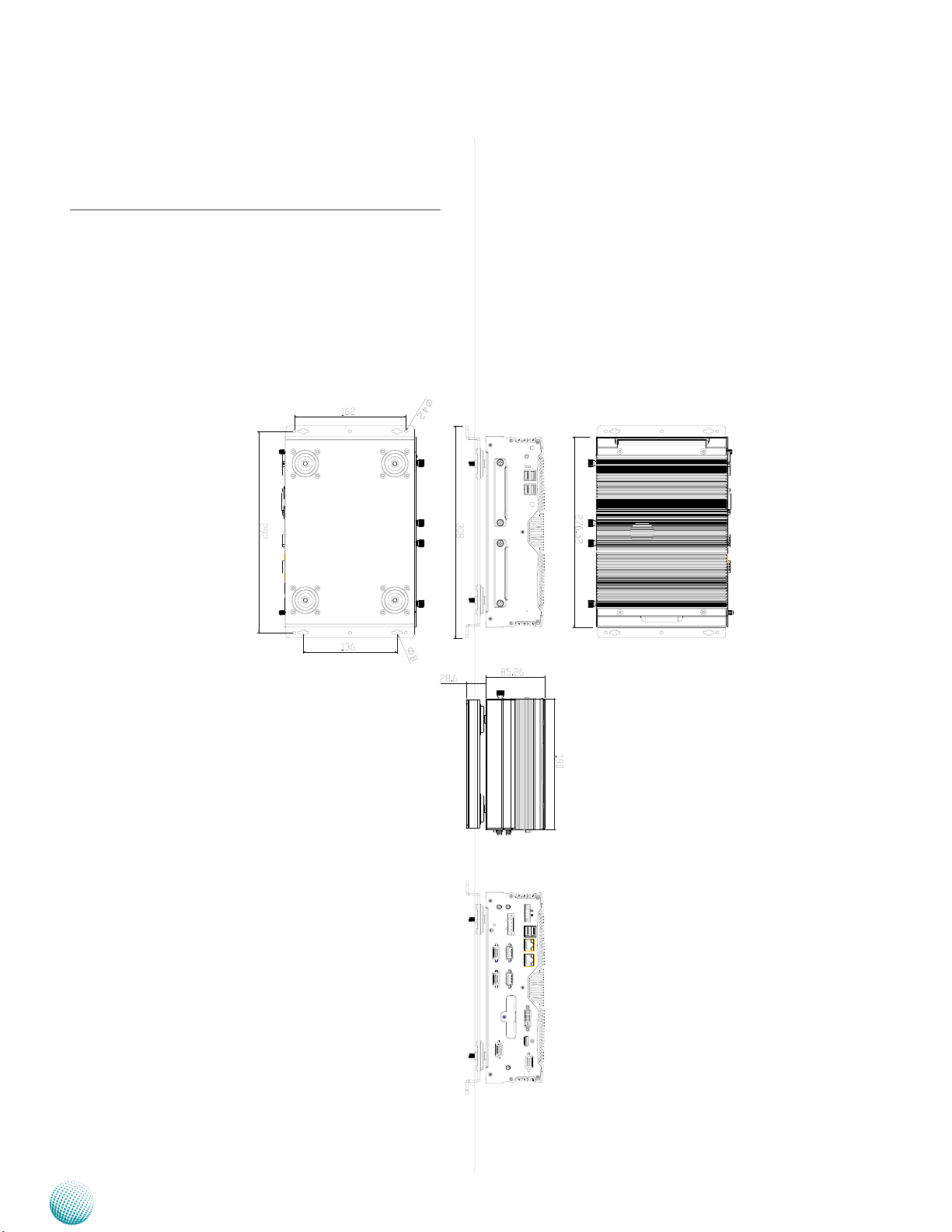
System Drawing
Mechanical dimensions of the LVC-5570 with the
suspension kit
Unit: mm
System Components
Embedded and Industrial Computing
7
Page 8
Chapter 2
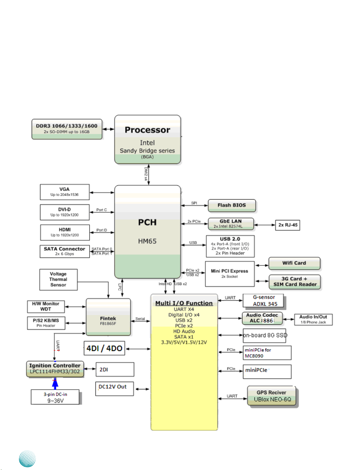
Block Diagram: The MainBoard
The block diagram depicts the relationships among the
interfaces and modules on the motherboard.
System Components
Embedded and Industrial Computing
8
Page 9
Chapter 2
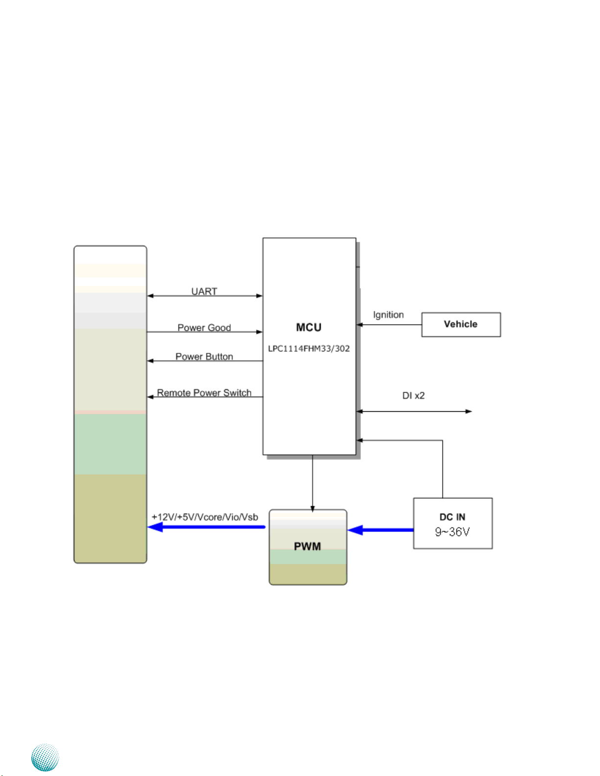
Block Diagram: The Ignition Board
The block diagram depicts the relationship between the
power ignition board and the mainboard.
System Components
Embedded and Industrial Computing
9
Page 10
Chapter 2
System Components
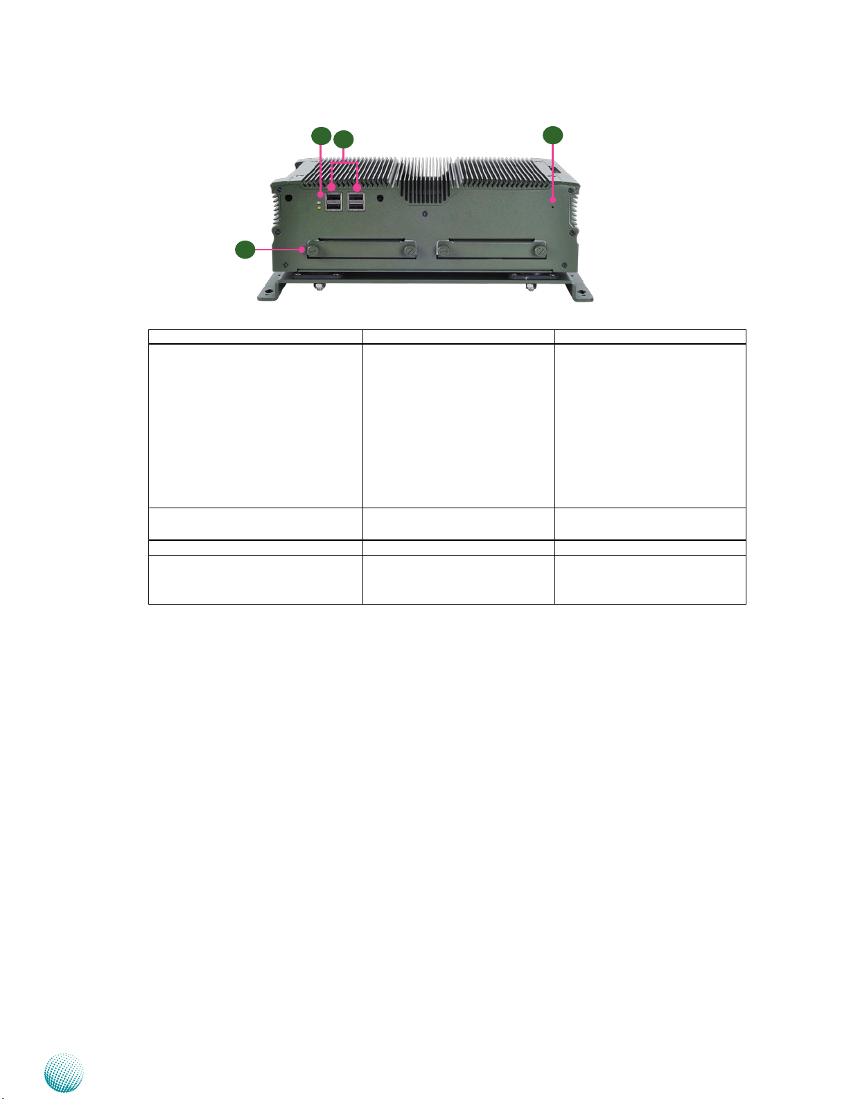
Front Components
F1 HDD (Yellow) and
Power LED (Green)
F2 Four USB 2.0 Ports USB type A connectors Dual USB Port #0, #1 and #2, #3
F3 Reset Switch A hardware reset button RST1 on page 24
F4 Hard Disk Slot External SATA 2.5” hard disk
F1
F3
F4
Component Description Pin Definition Reference
HDD
Blinking: data access •
activities
Off: no data access •
activities or no hard disk
present
Power
On: The computer is on.•
Off: The computer is off .•
drive for easy access and replacement of the data storage.
F3
(USB1,USB2) on page 25
SATA1/SATA2 on page 22
Embedded and Industrial Computing
10
Page 11
Chapter 2
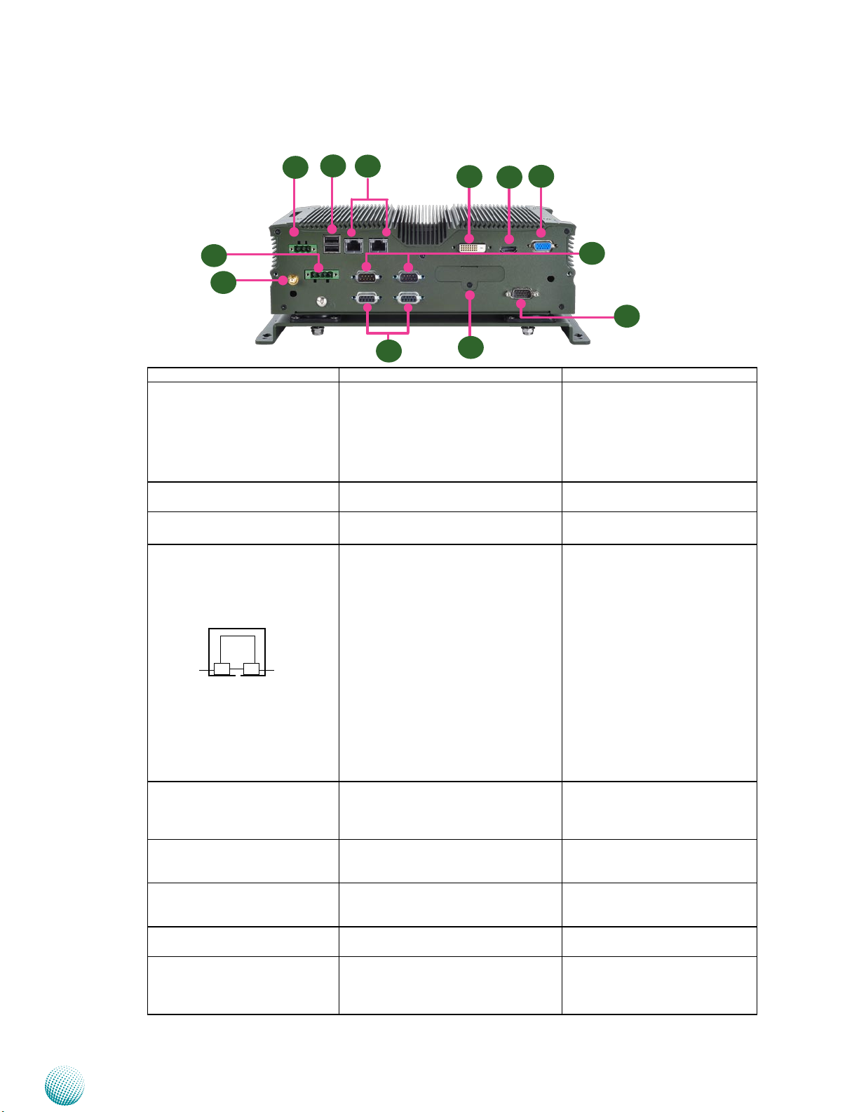
Rear Components
R1
R3
R4
R5
R6
System Components
R7
R2
R8
Component Description Pin Definition Reference
COM1 COM2
R10
R12
R1 Power-In (DC) Power-in with ignition support. The
LVC-5570 support a wide range of
R9
R11
DC_IN Connector (CN3) on page
25
power input (+9V ~ +36) including
the prevalent 12V and 24V vehicular
power system. It has a 2KV ESD
protection on the DC input and
ignition line.
R2 DC Relay Bypass 9~36V, 10A (GND, Power-Out)
CN2 on page 21
Integrated in 1x 4-pin terminal block
R3 Two USB 2.0 Ports USB type A connectors Dual USB Port Connector #4 and
#5 (USB3) on page 25
R4 Two 10/100/1000Mbps LAN
ports
Two RJ-45 (network) jacks with LED
indicators as described below
LANB1/LANB2 on page 25
LINK/ACT (Yellow)
On/Flashing: The port is linking •
and active in data transmission.
Off: The port is not linking.•
SPEED
LINK/ACT
SPEED (Green/Amber)
Amber: The connection speed is •
1000Mbps.
Green: The connection speed is •
100Mbps
Off: .The connection speed is •
10Mbps.
R5 DVI-D (*) A DVI-D port (single link) which
DVID1 on page 23
is provided by Intel HD Graphic
Engine. This port can support up to
1920x1200@60Hz resolution.
R6 HDMI Port (*) A DVI-D port (single link) which is
HDMI1 on page 23
provided by Intel HD Graphics 3000
(resolution: 1920x1200@60Hz).
R7 VGA Port (*) It connects an external VGA
VGA1 on page 23
monitor or projector (resolution:
2048x1536@75Hz)
R8 GPS Antenna It connects an antenna for the build-
in GPS module.
R9 Serial Ports (from left to right:
COM1/COM2)
COM1 and COM2 provide RS232/
RS422/RS485 communications with
RS-232 COM Port (COM1, COM2)
on page 19
a dip switch selecting among these
standards.
Embedded and Industrial Computing
11
Page 12
Chapter 2
R10 3G Audio (optional) and PC
Audio Ports (†)
R11 MIO Connector (†) A DE-15 male connector for 4 Digital-
R12 External SIM Card Readers
with cover (SIM2/SIM1)
* Only DVI-D +VGA or HDMI + VGA can work at the same time.
†In order to offer more flexibility for port arrangement, the connectors will not be installed as shown
here. Instead, we will provide the cables (one with D-sub 9 connector and the other one with DE-15
connector) for you to fix the ports on the panel.
System Components
Component Description Pin Definition Reference
D-sub 9 connector for MIC input and
HD Audio output (w/2 Watt) from
LEK-IOA6.
The 3G audio is provided by AUDIO
TLV320AIC1106 TSSOP20P (designed
by TI). It enables 3G wireless audio
communication with MIC-in and
EAR-out connectors. The 3G service is
connected via the external SIM (SIM2)
card reader (see R12 below) and the
MCARD1 PCIe connector.
In & 3 Digital-output, at 12V level.
The digital input helps triggering
between open and closed circuit such
as PIRs, door/window contact, glass
break detector. And the output can
connect to devices such as sirens.
In addition to the above Digital I/O
function, two IGN_in pins can be used
to wake up the system even when the
system is shut down.
External SIM Card Reader for 3G
wireless Internet service. The
system supports triple 3G Internet
service with three SIM card readers.
The SIM2 connector (left) together
with an internal PCIe expansion
(MCARD1) supports 3G SMS/Ring
wake-up and 3G voice service (with
the recommended 3G module: Sierra
MC8090/8092 (power voltage 3.6V)).
There is also a jumper setting for
selecting the connector’s voltage
from 3.3V or 3.6V.
COM1/COM2 on page 18
J3 on page 19
SIM1/SIM2 on page 20
Embedded and Industrial Computing
12
Page 13
Chapter 3
Chapter 3:
Board Layout
Connectors
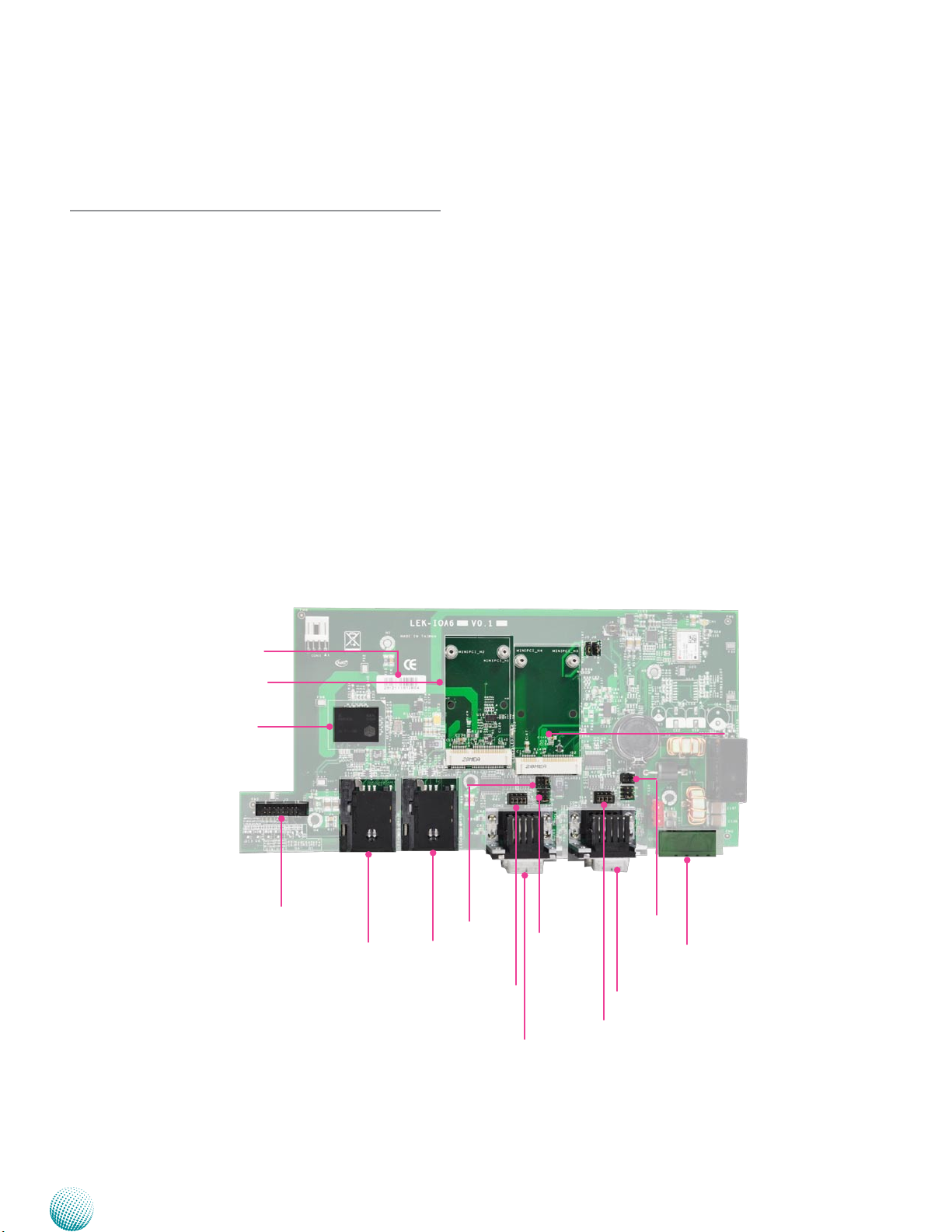
The following picture highlights the location of the COM
ports and other connectors on the expansion card. Refer
to the table 3.1 Connector List for more details.
Board Layout
HDDSL1
MPCIE1
Onboard 8G SSD
J3
SIM1
SIM2
SCT4
SCT3
COM2
MCARD1
COM2
SCT2
SCT1
CN2
COM1
SCT1
Embedded and Industrial Computing
LEK-IOA6
13
Page 14
Chapter 3
Ignition Board Connectors
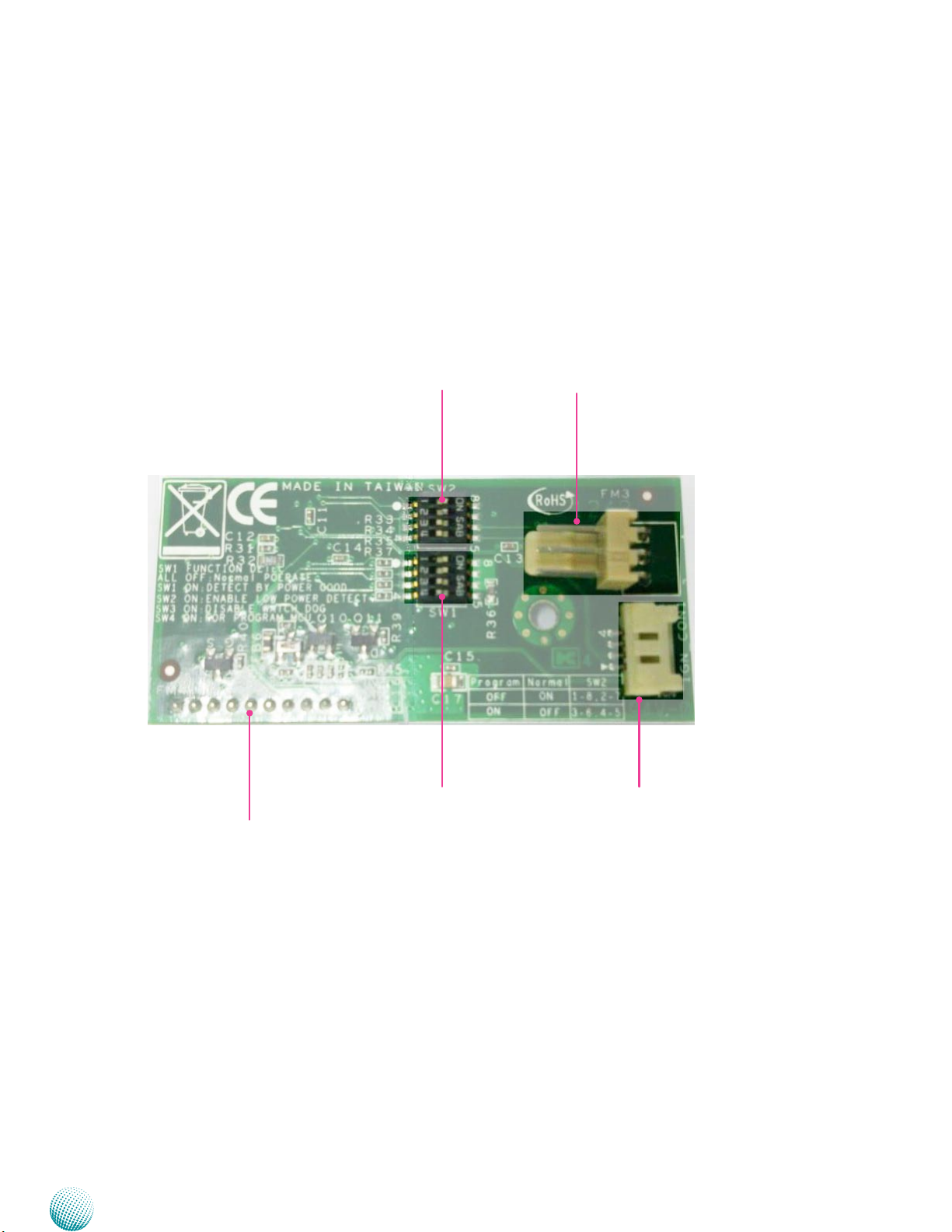
The following picture highlights the location of ignition
board connectors. The ignition board also equips with
jumpers that can be switched to enable or disable
automatic power management control. Refer to the table
3.2 Connector List for more details.
Board Layout
IGNITION1
SW2
SW1
CN1
IGN_CON1
Embedded and Industrial Computing
LEK-IG1
14
Page 15
Chapter 3
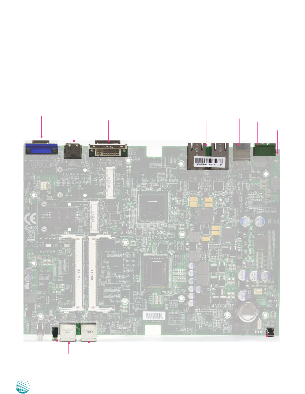
External Connectors
The following picture highlights the location of external
input/output connectors. Refer to the table 3.3 Connector
List for more details.
Board Layout
VGA1
HDMI1
DVID1
LAN1/LAN2
USB3
CN3
CN4/
DCJK1
(optional)
USB1
LED1
Embedded and Industrial Computing
USB2
RST1
LEB-5570
15
Page 16
Chapter 3
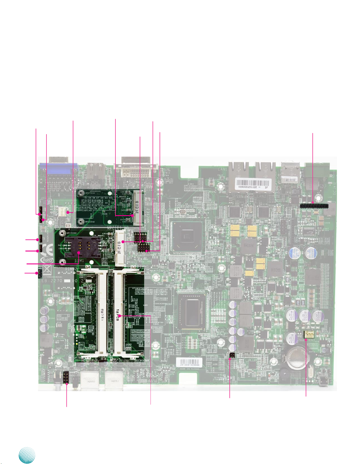
Internal Connectors and Jumpers
The following picture highlights the location of internal
connectors and jumpers. Refer to the table 3.3 Connector
List for more details.
Board Layout
CMOS2
COMSLT2
COMSLT1
SIM1
SATA_PW2
CMOS1
FAN2
MPCIE2
MPCIE1
LPC1
SPI1
Ignition1
FRONT1
Embedded and Industrial Computing
SO-DIMM
J1
FAN1
LEB-5570
16
Page 17
Chapter 3
Internal Connectors and Jumpers
(backside)
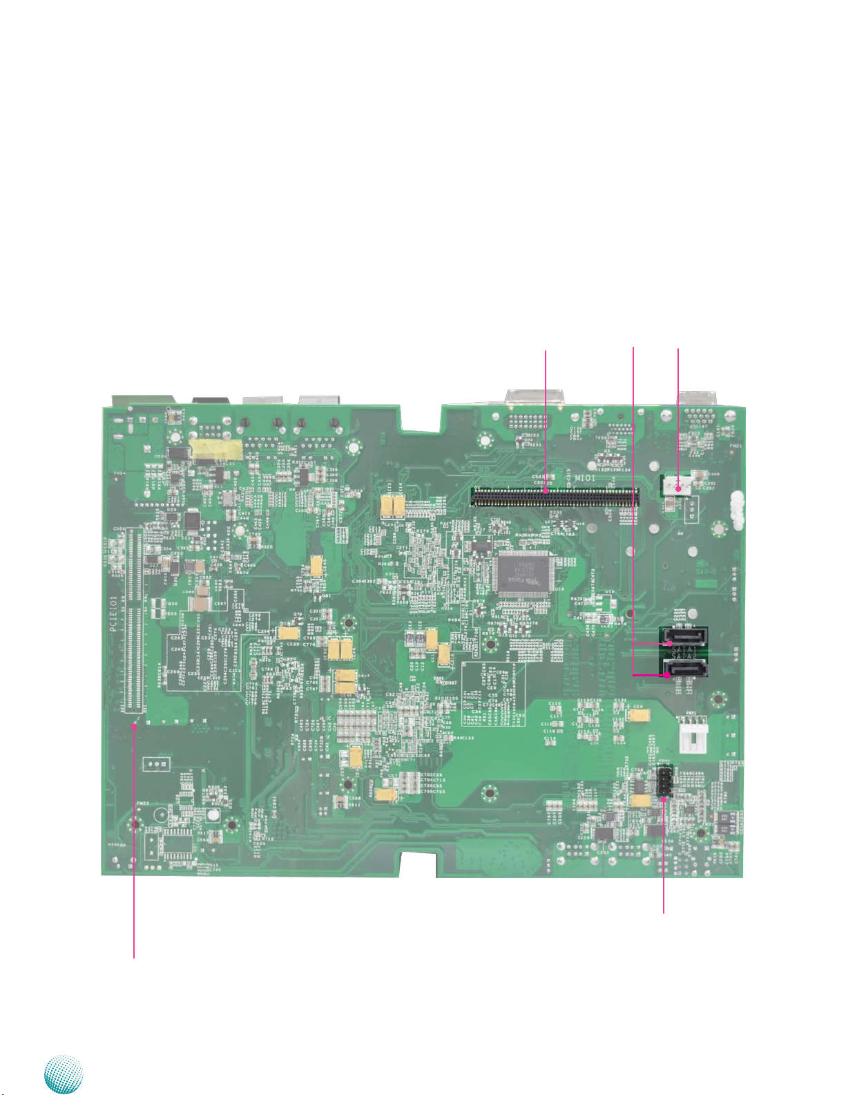
The following picture highlights the location of internal
connectors and jumpers on the backside of the board.
Refer to the table 3.3 Connector List for more details.
Board Layout
MIO1
SATA1
SATA2
SATA_PWR1
PCIEIO1
Embedded and Industrial Computing
KBM1
LEB-5570
17
Page 18
Chapter 3
Board Layout
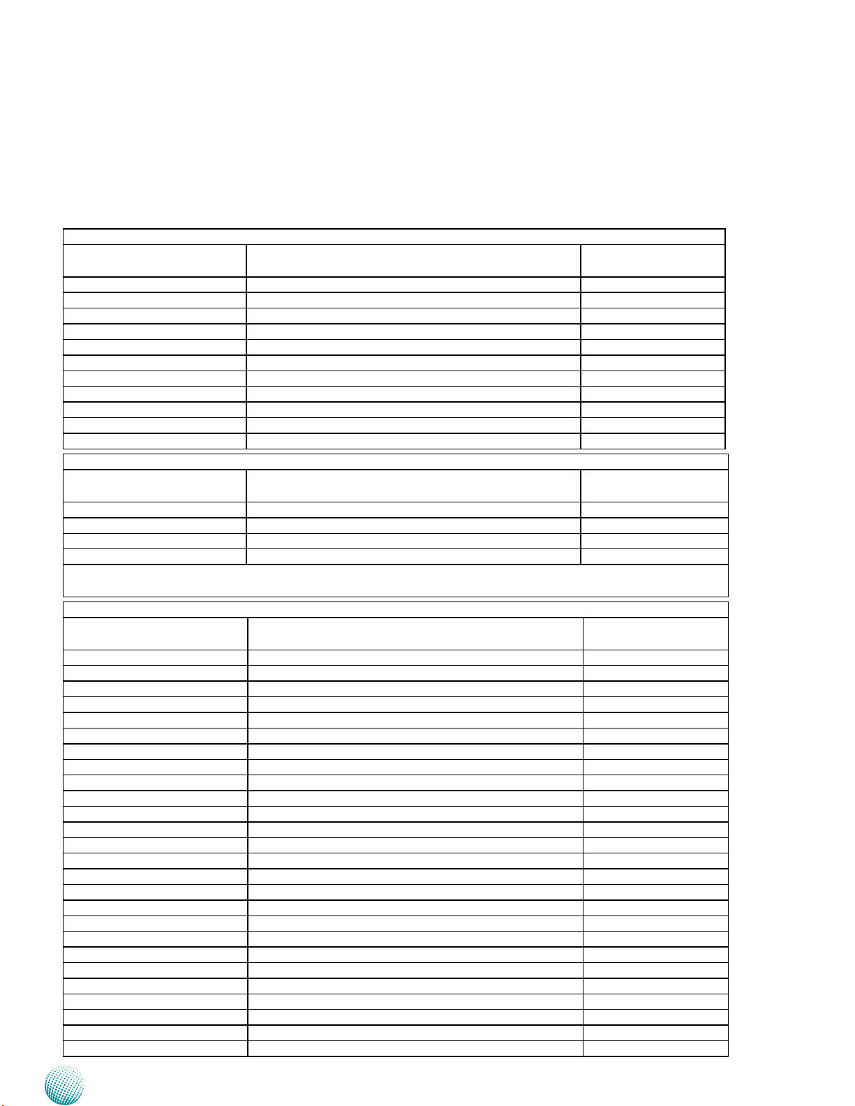
Connectors and Jumpers List
The tables below list the function of each of the board
jumpers and connectors by labels shown in the above
section. The next section in this chapter gives pin
definitions and instructions on setting jumpers.
Table 3.1 Connector List for LEK-IOA6 Board
Labels Function Pin Denition Refer-
ence Page
CN2 DC Relay Bypass P21
COM1 RS232/422/485 Serial Port P19
COM1 3G Audio Connector (D-Sub) P19
COM2 RS232/422/485 Serial Port P19
COM2 HD Audio Connector (D-Sub) P19
HDDSL1 Enable/disable onboard SSD P21
J3 DIO port P20
J6 Select MCARD1 Voltage for Module Sierra MC809x P21
SCT1/SCT2 Select COM1 Protocol Setting P19
SCT3/SCT4 Select COM2 Protocol Setting P19
SIM1/SIM2 SIM Card Reader (along with MCARD1 for 3G service) P21
Table 3.2Connector List for LEK-IG1 Board
Labels Function Pin Denition Refer-
ence Page
CN1 MCU Programming Connector P27
IGNITION1 Ignition Control Connector P27
IGN_CON1 Power Connector P27
SW1 Power Ignition Behavior Switch P26
The ignition board also equips with jumpers that can be switched to enable or disable automatic power management
control.
Table 3.3 Connector List for LEB-5570 Board
Labels Function Pin Denition Refer-
ence Page
CMOS1 Cleaning CMOS Data Including RTC P25
CMOS2 Cleaning CMOS Data Only P25
COMSLT1 Daughter board LEK-IOA6 enable/disable P25
COMSLT2 Daughter board LEK-IG1 enable/disable P25
CN3 Power Connector with Power -ignition Control P25
DCJK1 (optional) Optional DC Jack Type of Power Connector P25
DVID1 DVI-D Connector P23
FAN1/FAN2 System Fan Connector P23
Front1 Front Panel Function Pin Header P22
HDMI1 HDMI Port P23
Ignition1 Connector for power Ignition Control P26
J1 PEG16X Lane Function Selection P24
KBM1 PS/2 Keybaord and Mouse Connector P26
LAN1/LAN2 Ethernet Connector 1/Ethernet Connector 2 P25
LPC1 Low Pin Count Interface Reserved for factory use
MIO1 COM and Audio Expansion Card Connector P22
MPCIE1 Mini-PCIe Connector P24
MPCIE2 Mini-PCIe Connector P24
RST1 Reset Button P24
SATA1/SATA2 Serial-ATA Connector (SATA2 supports SATA-DOM) P22
SATA_PWR1 SATA Power Connector P22
SATA_PW2 Switch for SATA port 2 power state P22
SIM1 SIM Card Reader P25
SPI1 Serial Peripheral Interface Bus Reserved for factory use
USB1/USB2/USB3 USB Type A Connector #0,1; #2,3; #4,5 P25
VGA1 VGA Port P23
Embedded and Industrial Computing
18
Page 19
Chapter 3
Board Layout
Jumper Settings
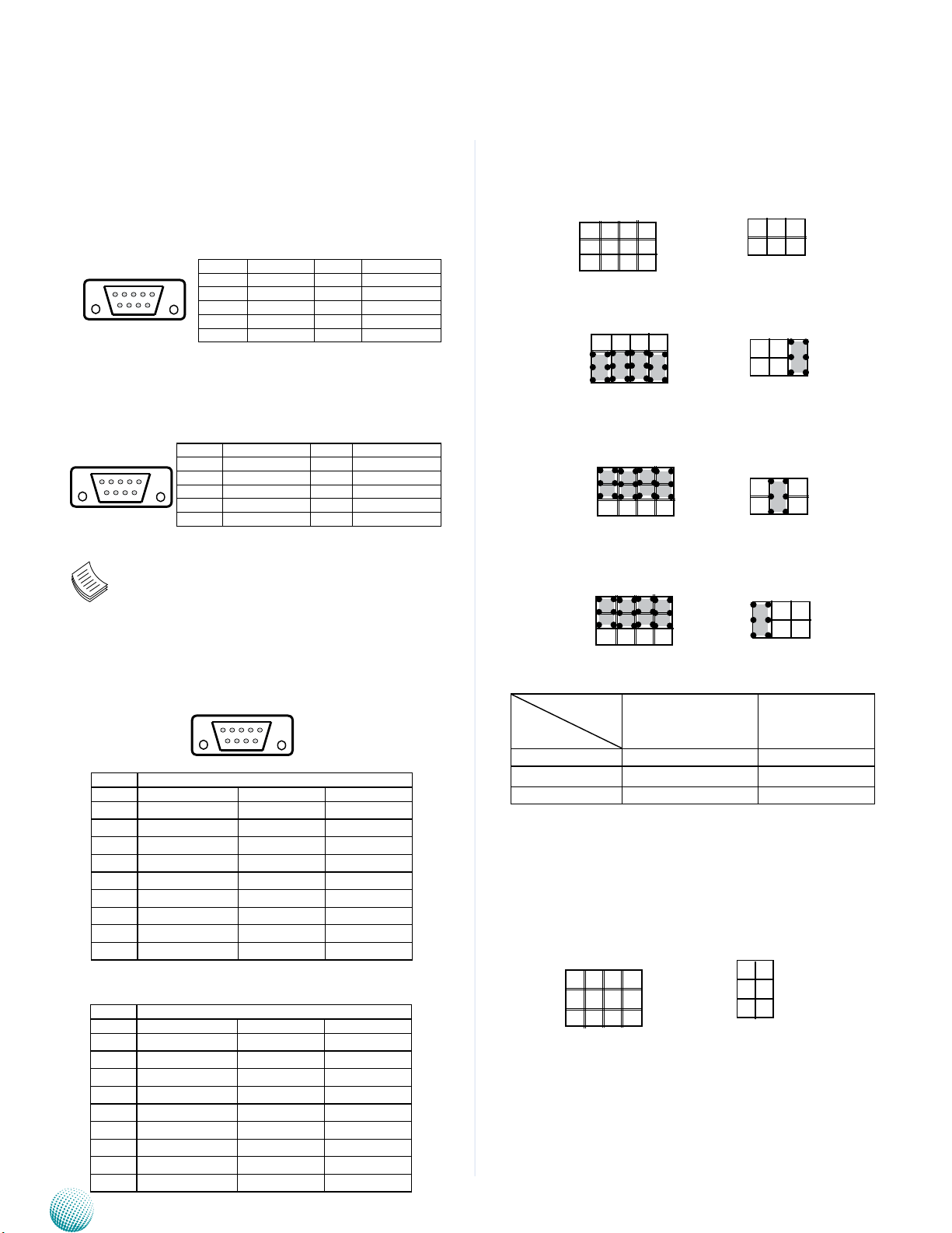
LEK-IOA6 Board
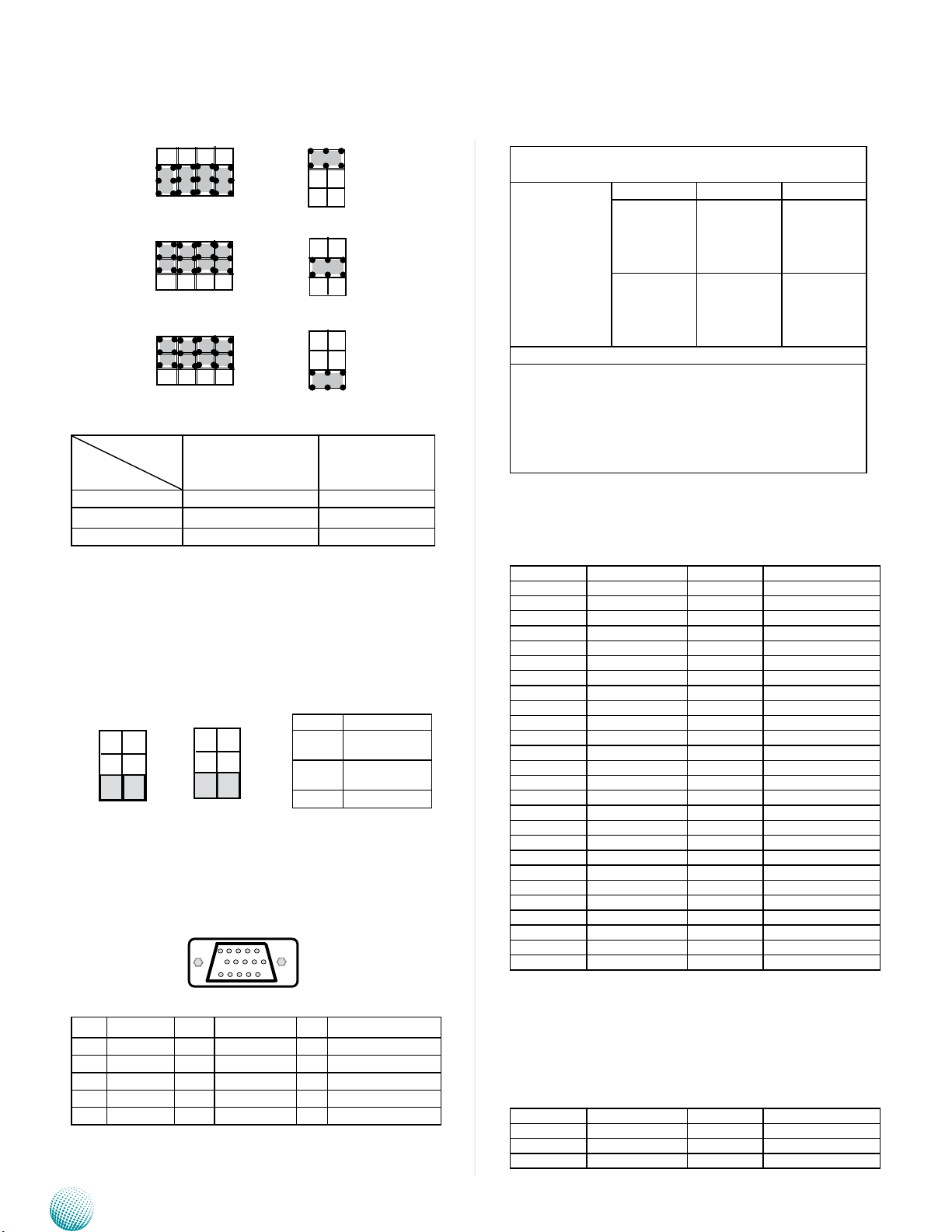
3G Audio Connector (COM1): a D-sub 9 male connector
for 3G Audio
12345
6789
Line-out Audio Jack (COM2): a D-sub 9 male connector
for HD Audio
12345
6789
Note: The driver for the VGA and Audio ports
should be installed with the following order:
Chipset INF->Graphic->Audio
COM1 RS-232 Serial Port(COM1): a RS-232/422/485 port
through the D-SUB9 connector.
Pin No. Function Pin No. Function
1 3G_MIC_R 6 3G_MIC_L
2 N/A 7 N/A
3 3G_EAROR 8 GND_AUD1
4 3G_EAROL 9 GND_AUD1
5 N/A 10 N/A
Pin No. Function Pin No. Function
1 AUDIO_OUT_R 6 AUDIO_OUT_L
2 N/A 7 N/A
3 AMPOUT_R 8 GND_AUD
4 AMPOUT_L 9 GND_AUD
5 N/A 10 N/A
12345
SCT1, SCT2: Select COM1 Protocol Setting
SCT2
5
6
9
5
1
SCT1
12
8
4
RS-232
9
5
1
12
8
4
5
6
RS-422
9
5
1
12
8
4
5
6
RS-485
9
5
1
Switch
12
8
4
5
6
SCT1 SCT2
1
2
1
2
1
2
1
2
6789
Pin No. Pin Name
RS-232 RS-422 RS-485
1 DCD TXD- DATA2 RXD TXD+ DATA+
3 TXD RXD+
4 DTR RXD5 GND
6 DSR
7 RTS
8 CTS
9 RI
RS-232/422/485 Serial Port(COM2): a RS-232/422/485
port through the D-SUB9 connector.
Pin No. Pin Name
RS-232 RS-422 RS-485
1 DCD TXD- DATA2 RXD TXD+ DATA+
3 TXD RXD+
4 DTR RXD5 GND
6 DSR
7 RTS
8 CTS
9 RI
Embedded and Industrial Computing
Protocol
RS-232 (default) 1-5, 2-6, 3-7, 4-8 1-2
RS-422 5-9, 6-10, 7-11, 8-12 3-4
RS-485 5-9, 6-10, 7-11, 8-12 5-6
SCT3, SCT4: Select COM2 Protocol Setting
9
5
1
SCT3
12
8
4
SCT4
1
3
5
2
4
6
19
Page 20
Chapter 3
Board Layout
9
5
1
9
5
1
9
5
1
Switch
12
8
4
12
8
4
12
8
4
1
3
5
SCT3 SCT4
2
4
6
Protocol
RS-232 (default) 1-5, 2-6, 3-7, 4-8 1-2
RS-422 5-9, 6-10, 7-11, 8-12 3-4
RS-485 5-9, 6-10, 7-11, 8-12 5-6
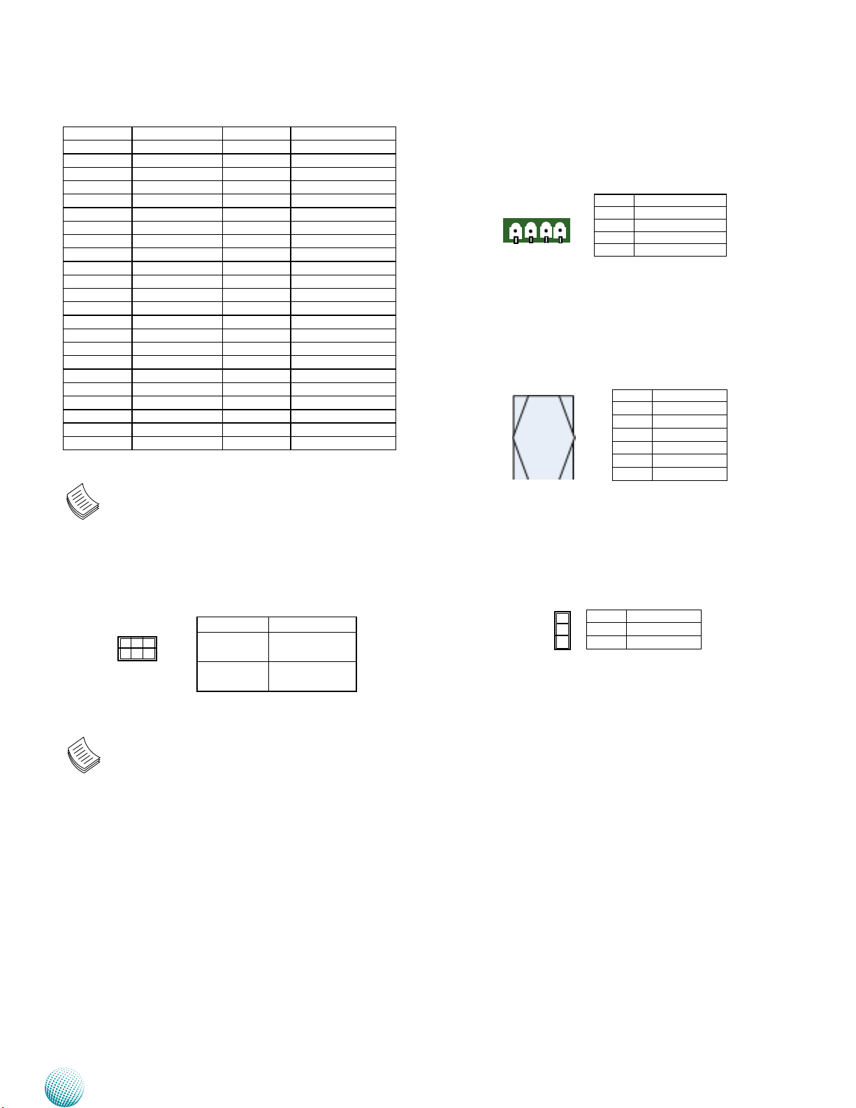
PCOM1, PCOM2: Select COM1 and COM2 Pin9 Function
(in RS-232) respectively. The Ring indicator pinout of
the RS-232 COM port can be altered according to the
following jumper settings.
J1
1
3
5
2
4
6
J2
1
3
5
2
4
6
Pin No. Function
1-2 Supply +5V to
the Device
3-4 Supply +12V to
the Device
5-6 Ring-in (default)
Digital Input and Output (J3): A DE-15 Male Connector
for 4 DI & 3 DO, 12V
15 11
Maximum input/output current for each port is
100mA
For all Input/
output pins:
Voltage Logic Register
DI: <0.8V
Low 0
Do: <0.4V
DI: 0.9 ~ 5V
High 1
Do:5V
The default BIOS value is 1 for DI and 1 for DO
Pin 11 is used for remote power switch.1.
Pin 6 is used for relay power switch.2.
Pin12 and pin13 can be used for DI wake-up 3.
function (Refer to the flow chart in Chapter 4 and
the ISM in Appendix A).
MPCIE1: a Mini-PCIe connector with a SIM card reader
(SIM1). It supports both PCIe and USB signal type. We
recommend Sierra MC8790/8795 and Novatel NVTL E346.
Wi-Fi modules are also supported in this connector.
Pin Signal Pin Signal
1 PCIE_WAKE_N 2 VCC3P3_MINI1
3 N/A 4 GND
5 N/A 6 V1P5_MPCIE
7 MINI_CLKREQ_N1 8 VREG_USIM1
9 GND 10 UIM1_DATA
11 PCIE_CKN5 12 UIM1_CLK
13 PCIE_CKP5 14 UIM1_RESET
15 GND 16 UIM1_VPP
17 RSV 18 GND
19 RSV 20 RF_KILL_1
21 GND 22 MINIPCIE_RST_N
23 PCH_PCIE_RXN5 24 VCC3P3_MINI1
25 PCH_PCIE_RXP5 26 GND
27 GND 28 V1P5_MPCIE
29 GND 30 SMBCLK_RESUME
31 PCH_PCIE_TXN5 32 SMBDATA_RESUME
33 PCH_PCIE_TXP5 34 GND
35 GND 36 PCH_USB_N13
37 GND 38 PCH_USB_P13
39 VCC3P3_MINI1 40 GND
41 VCC3P3_MINI1 42 3G_LED1_WWAN_N
43 GND 44 N/A
45 N/A 46 N/A
47 N/A 48 V1P5_MPCIE
49 N/A 50 GND
51 N/A 52 VCC3P3_MINI1
5 1
Pin Signal Pin Signal Pin Signal
1 RIO_IN0 6 RIO_OUT0 11 EXT_POWER_ON
2 RIO_IN1 7 RIO_OUT1 12 IGN_IN0
3 RIO_IN2 8 RIO_OUT2 13 IGN_IN1
4 RIO_IN3 9 RIO_OUT3 14 GND
5 GND 10 GND 15 12V_OUT
Embedded and Industrial Computing
MCARD1: a Mini-PCIe connector with a SIM Card
Reader(SIM2). It supports only USB signal type. We
recommend Sierra MC 8090/8355/8790/8795 and
Novatel NVTL E346. In addition, it also support SMS/
Ring power-on function and voice communication ( with
MC8090)
Pin Signal Pin Signal
1 N/A 2 VCC3P6_MINI1
3 N/A 4 GND
5 N/A 6 N/A
20
Page 21
Chapter 3
Board Layout
Pin Signal Pin Signal
7 N/A 8 VREG_USIM2
9 GND 10 UIM2_DATA
11 N/A 12 UIM2_CLK
13 N/A 14 UIM2_RESET
15 GND 16 UIM2_VPP
17 N/A 18 GND
19 N/A 20 RF_KILL_2
21 GND 22 N/A
23 N/A 24 VCC3P6_MINI1
25 N/A 26 GND
27 GND 28 N/A
29 GND 30 N/A
31 N/A 32 3G_WAKE_MCU
33 3G_RESET_N 34 GND
35 GND 36 PCH_USB_N12
37 GND 38 PCH_USB_P12
39 VCC3P6_MINI1 40 GND
41 VCC3P6_MINI1 42 3G_LED2_WWAN_N
43 GND 44 N/A
45 PCM_CLK 46 N/A
47 PCM_DIN 48 N/A
49 PCM_OUT 50 GND
51 PCM_SYNC 52 VCC3P6_MINI1
Note: Jumper J6 is used to select power voltage
for MCARD1.
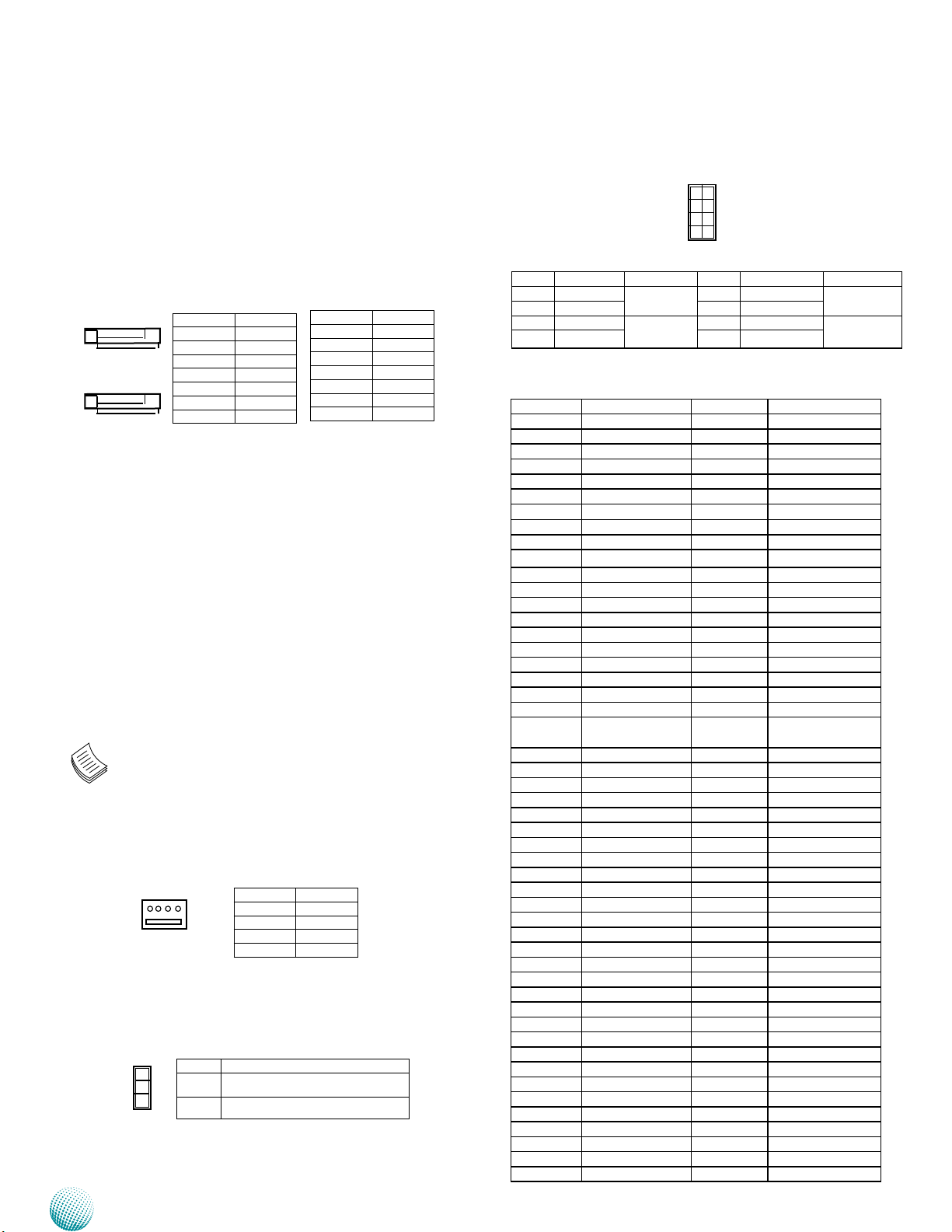
DC Relay Bypass (CN2) : 9~30V, 10A DC power input and
output Integrated in a 4-pin terminal.
4 3 2 1
Pin No. Function
1 P930V
2 GND
3 GND_930V
4 P930V_OUT
SIM Card Socket (SIM1/SIM2): SIM1 and SIM2 are paired
with connector MPCIE1 and MCARD1 respectively.
C1 C3
C5 C7
Pin No. Description
C1 VREG
C2 USIM_RESET
C3 USIM_CLK
C5 GND
C6 USIM_VPP
C7 USIM_DATA
Select MCARD1 Voltage for Module Sierra MC809x
(J6) : The default is 3.3V for most 3G mini card; for Sierra
Airprime HSPA+ mini card , set it to +3.6V.
Enable or disable the onboard SSD memory (HDDSL1)
Pin No. Pin Name
5
6
1
2
1-3 short
2-4 short
3-5 short
4-6 short
Enable (default)
Disable
Note: When trying to install an OS on the external
SATA 2.5 hard disk or SSD, disable it first by setting
the jumpers accordingly. Enable it after finishing
the OS installation.
1
2
3
Pin No. Description
1-2 3.3V
2-3 3.6V
Embedded and Industrial Computing
21
Page 22
Chapter 3
Board Layout
LEB-5570 Board
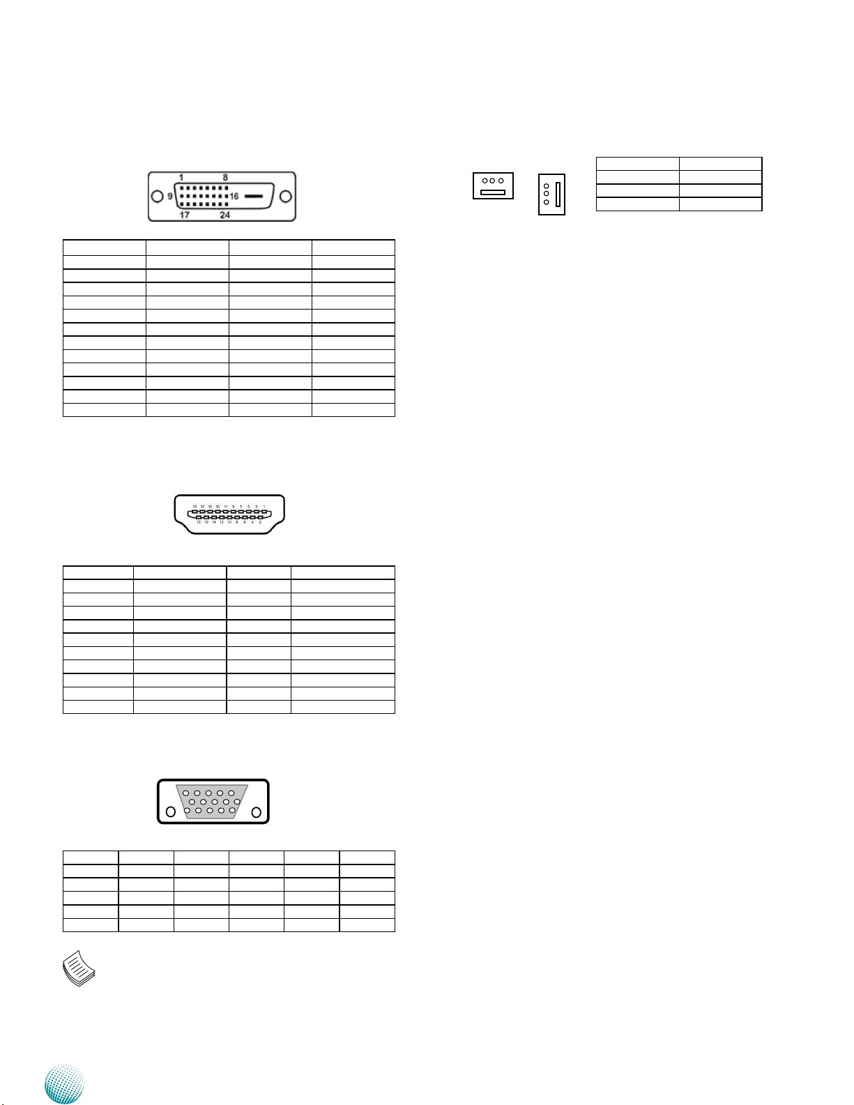
Serial-ATA Connector (SATA1/SATA2): It is for connecting
a 2.5’’ hard disk to be served as your system’s storage. It
can support SATA III which features Data transfer rates up
to 6.0 Gb/s (600 MB/s). The SATA connector also supports
SATA-DOM (the power line of SATA-DOM can be disabled
with a jumper on, see SATA_PW2).
1 2 3 4 5 6 7
SATA1
7 6 5 4 3 2 1
SATA2
Pin No. Function
1 GND
2 TX0_P
3 TX0_N
4 GND
5 RX0_N
6 RX0_P
7 GND
Pin No. Function
1 GND
2 TX1_P
3 TX1_N
4 GND
5 RX1_N
6 RX1_P
7 VCC5
The controller contains two modes of operation—a
legacy mode using I/O space, and an AHCI mode using
memory space. Software that uses legacy mode will not
have AHCI capabilities.
The AHCI ( Advanced Host Controller Interface) is a
programming interface which defines transactions
between the SATA controller and software and enables
advanced performance and usability with SATA. Platforms
supporting AHCI may take advantage of performance
features such as no master/slave designation for SATA
devices—each device is treated as a master—and
hardware assisted native command queuing. AHCI also
provides usability enhancements such as Hot-Plug.
Use the BIOS menu to configure your hard disk
to be AHCI compatible.
4-pin Serial-ATA Power Connector (SATA_PWR1): It is
for connecting the SATA power cord.
Pin No. Function
1 +12V
4 3 2 1
2 GND
3 GND
4 +5V
SATA_PW2: A switch for supply of SATA Connector II’s
power.
1
2
3
Embedded and Industrial Computing
Pin No. Pin Name
1-2 SATAII Connector without power
2-3 SATA II Connector with 5V power
Front Panel Function Pin Header (FRONT1): It provides
LED signal and button function on the front panel.
10
Pin No. Pin Name Function Pin No. Pin Name Function
1 HD_LED+ HDD LED 2 PWR_LED+ Power LED
3 HD_LED- 4 PWR_LED5 Reset System Reset
7 GND 8 GND
Button
9
8
7
6
5
4
3
2
1
6 POWER_BTN Power On/Off
Push Button
Mini PCI Express Connector (MIO1) on the mainboard:
COM and Audio Expansion Card Connector
PIN Pin Name PIN Pin Name
1 GND 51 HDA_BCLK
2 SATATXN2 52 HDA_SYNC
3 SATATXP2 53 HDA_RST
4 GND 54 HDA_SDIN0
5 SATARXN2 55 HDA_SDO
6 SATARXP2 56 SPK
7 GND 57 VCC3_SB
8 VCC3P3_PS 58 VCC3_SB
9 VCC3P3_PS 59 VCC3_SB
10 VCC3P3_PS 60 VCC3_SB
11 GND 61 VCC3_SB
12 PCIE_RXN5 62 PCIE_RXN6
13 PCIE_RXP5 63 PCIE_RXP6
14 PCIE_TXN5 64 PCIE_TXN6
15 PCIE_TXP5 65 PCIE_TXP6
16 PCIE_CKN5 66 PCIE_CKN6
17 PCIE_CKP5 67 PCIE_CKP6
18 IGN_DI2 68 IGN_DI1
19 PLTRST 69 SMBCLK_
20 WAKE_N 70 SMBDATA
21 DCIN_VCC 71 REMOTE_POWER_
22 VCC12_PS 72 3G_POWER_ON
23 VCC5_SB 73 USB_N12
24 VCC5_SB 74 USB_P12
25 VCC5 75 GND
26 VCC5 76 USB_N13
27 VCC5 77 USB_P13
28 GND 78 GND
29 DGOUT_0 79 DGIN_0
30 DGOUT_1 80 DGIN_1
31 DGOUT_2 81 DGIN_2
32 DGOUT_3 82 DGIN_3
33 GND 83 GND
34 COM3_DCD# 84 COM1_DCD#
35 COM3_RI# 85 COM1_RI#
36 COM3_CTS# 86 COM1_CTS#
37 COM3_DTR# 87 COM1_DTR#
38 COM3_RTS# 88 COM1_RTS#
39 COM3_DSR# 89 COM1_DSR#
40 COM3_SOUT 90 COM1_SOUT
41 COM3_SIN 91 COM1_SIN
42 GND 92 GND
43 COM4_DCD# 93 COM2_DCD#
44 COM4_RI# 94 COM2_RI#
45 COM4_CTS# 95 COM2_CTS#
46 COM4_DTR# 96 COM2_DTR#
47 COM4_RTS# 97 COM2_RTS#
48 COM4_DSR# 98 COM2_DSR#
49 COM4_SOUT 99 COM2_SOUT
50 COM4_SIN 100 COM2_SIN
ON
22
Page 23
Chapter 3
Board Layout
DVI-D Connector (DVID1): A single link DVI-D Connector
Pin No. Description Pin No. Description
1 TXD_2- 2 TXD_2+
3 GND 4 N/A
5 N/A 6 DDC_CLK
7 DDC_DATA 8 N/A
9 TXD_1- 10 TXD_1+
11 GND 12 N/A
13 N/A 14 VCC5
15 GND 16 HPD
17 TXD_0- 18 TXD_0+
19 GND 20 N/A
21 N/A 22 GND
23 TXD_CLK_P 24 TXD_CLK_N
HDMI Connector (HDMI1): An HDMI Connector
System FAN Connector (FAN1/FAN2)
FAN1
3 2 1
FAN2
Pin No. Description
3
2
1
1 GND
2 VCC5
3 FAN TAC
Pin No. Description Pin No. Description
1 HDMI_DATP2_P 2 GND
3 HDMI_DATP2_N 4 HDMI_DATP1_P
5 GND 6 HDMI_DATP1_N
7 HDMI_DATP0_P 8 GND
9 HDMI_DATP0_N 10 HDMI_CLK_P
11 GND 12 HDMI_CLK_N
13 N/A 14 N/A
15 HDMI_DDC_CLK 16 HDMI_DDC_DAT
17 GND 18 PHDMI
19 HDMI_HPD
VGA (VGA1)
5 4 3 2 1
15 14 13 12 11
Pin Signal Pin Signal Pin Signal
1 RED 6 CRT DET 11 N/A
2 GREEN 7 GND 12 DDC DAT
3 BLUE 8 GND 13 HSYNC
4 N/A 9 VCC5 14 VSYNC
5 GND 10 GND 15 DDC CLK
Note: The driver for the VGA and Audio ports
should be installed with the following order:
Chipset INF->Graphic->Audio
Embedded and Industrial Computing
23
Page 24
Chapter 3
Board Layout
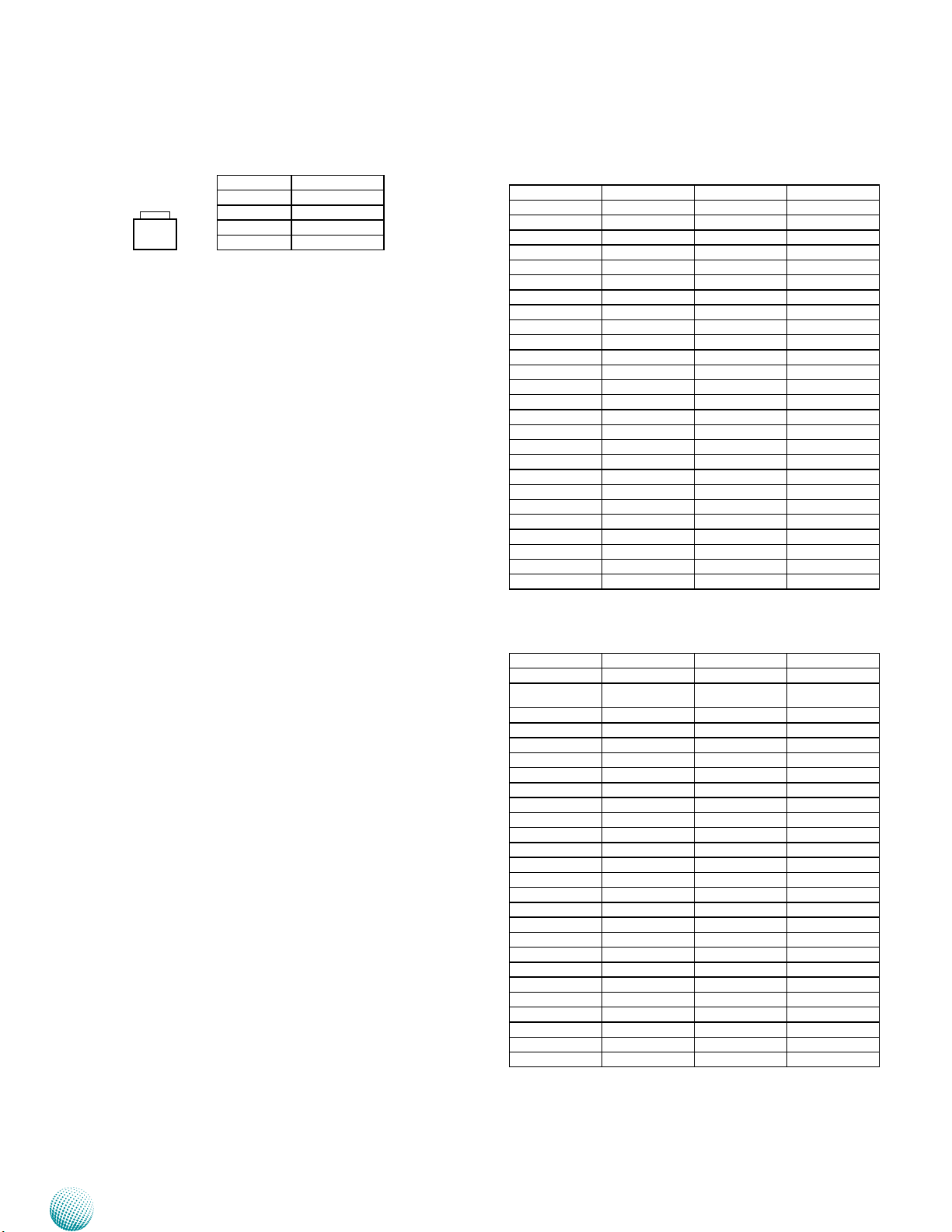
Reset Button (RST1)
2
4
1
3
Pin NO. Description
1 RST_BTN
2 GND
3 GND
4 N/A
MPCIE1: Mini-PCIe Connector with one SIM Card
Reader(SIM1). It supports both Wi-Fi and 3G module.
Pin Signal Pin Signal
1 WAKE# 2 VCC3.3
3 N/A 4 GND
5 N/A 6 VCC1.5
7 CLKREQ# 8 USIM_PWR
9 GND 10 UIM_DATA
11 PCIE_CLK_N3 12 UIM_CLK
13 PCIE_CLK _P3 14 UIM_RESET
15 GND 16 UIM_VPP
17 RSV 18 GND
19 RSV 20 N/A
21 GND 22 PLTRST
23 PCIE_RX_N3 24 VCC3.3
25 PCIE_RX_P3 26 GND
27 GND 28 VCC1.5
29 GND 30 SMBCLK
31 PCIE_TX_N3 32 SMBDATA
33 PCIE_TX_P3 34 GND
35 GND 36 USB_N8
37 GND 38 USB_P8
39 VCC3.3 40 GND
41 VCC3.3 42 N/A
43 GND 44 N/A
45 RSV 46 N/A
47 RSV 48 VCC1.5
49 RSV 50 GND
51 RSV 52 VCC3.3
MPCIE2: Mini-PCIe Connector. It does not come with a
SIM card reader so only Wi-Fi modules are supported.
Pin Signal Pin Signal
1 WAKE# 2 VCC3.3
3 N/A 4 GND
5 N/A 6 VCC1.5
7 CLKREQ# 8 N/A
9 GND 10 N/A
11 PCIE_CLK _N4 12 N/A
13 PCIE_CLK _P4 14 N/A
15 GND 16 N/A
17 RSV 18 GND
19 RSV 20 N/A
21 GND 22 PLTRST
23 PCIE_RX_N4 24 VCC3.3
25 PCIE_RX_P4 26 GND
27 GND 28 VCC1.5
29 GND 30 SMBCLK
31 PCIE_TX_N4 32 SMBDATA
33 PCIE_TX_P4 34 GND
35 GND 36 USB_N9
37 GND 38 USB_P9
39 VCC3.3 40 GND
41 VCC3.3 42 N/A
43 GND 44 N/A
45 RSV 46 N/A
47 RSV 48 VCC1.5
49 RSV 50 GND
51 RSV 52 VCC3.3
Embedded and Industrial Computing
24
Page 25

Chapter 3
Board Layout
SIM Card Socket (SIM1):
C1 C3
C5 C7
Pin No. Description
C1 UIM_PWR
C2 UIM_RST
C3 UIM_CLK
C5 GND
C6 UIM_VPP
C7 UIM_DAT
CN3: A power connector with power -ignition Control
1 2 3
Pin No. Pin Name
1 Ignition
2 GND
3 DC_VIN
DCJK1 (Optional): An optional DC Jack type of Power
Connector
Pin No. Pin Name
1 DC_VIN
2 GND
3 GND
LAN1/LAN2 Ports (LAN1/LAN2): The LAN ports are
provided by Intel 82574L Ethernet controller whose
interface complies with PCI-e 1.1 (2.5 Ghz). It has advanced
management features including IPMI pass-through via
SMBus or NC-SI, WOL, PXE remote boot, ISCSI boot and
VLAN filtering.
Pin No. Description
Fast Ethernet Gigabit Ethernet
1 TX+ BI_DA+
2 TX- BI_DA3 RX+ BI_DB+
4 -- BI_DC+
5 -- BI_DC6 RX- BI_DB7 -- BI_DD+
8 -- BI_DD-
Enable or Disable Daughter Board LEK-IOA6 (COMSLT1):
This jumper is for enabling or disabling COM3/COM4 of
daughter board LEK-IOA6.
Enable or Disable Daughter Board LEK-IG1 (COMSLT2):
This jumper is for enabling or disabling COM5/COM6 of
daughter board LEK-IG1. If this jumper is set to disable,
the ISM will not work (refer to Appendix A Using the Ignition
System Manager (ISM)).
1
2
3
Pin No. Pin Name
1-2 Disable
2-3 Enable
Dual USB 2.0 Port Connector #0 and #1 (USB1)
Dual USB 2.0 Port Connector #2 and #3 (USB2)
Dual USB 2.0 Port Connector #4 and #5 (USB3)
Pin No. Pin Name
1 VCCUSB
5 6 7 8
1 2 3 4
2 USB0N
3 USB0P
4 GND
5 VCCUSB1
6 USB1N
7 USB1P
8 GND
Clear CMOS jumper (CMOS1/CMOS2): It is for clearing
the CMOS data. CMOS 1clears CMOS data with real-time
clock (RTC) whereas CMOS2 clears CMOS data only.
1
2
3
Pin No. Pin Name
1-2 Normal (Default)
2-3 Clear CMOS and RTC (CMOS1)
Clear CMOS only (CMOS2)
To erase the CMOS data:
Turn off the computer and unplug the power cord.
Move the jumper cap from pins 1-2 (default) to pins 1.
2-3. Keep the cap on pins 2-3 for about 5-10 seconds,
then move the cap back to pins 1-2.
Pin No. Pin Name
1
2
3
Embedded and Industrial Computing
1-2 Disable
2-3 Enable
Plug the power cord and turn on the computer.2.
Enter BIOS setup to re-enter data.3.
25
Page 26
Chapter 3
Board Layout
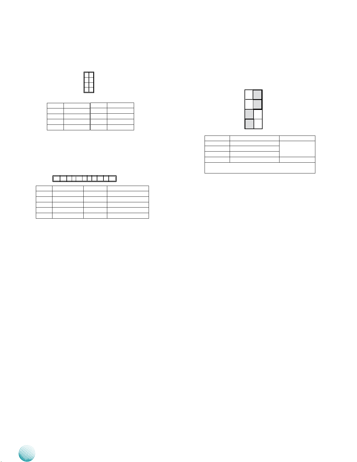
PS/2 Keyboard and Mouse Connector (KBM1)
1
2
3
4
5
6
7
8
Pin No. Pin Name
1 VCC5
3 MDATA
5 KDATA
7 GND
Pin No. Pin Name
2 MCLK
4 NC
6 NC
8 KCLK
Ignition Connector on Board (ignition1): Power
ignition connector.
1 2 3 4 10
Pin No. Pin Name Pin No. Pin Name
1 DCIN_VCC 6 DC2DC_PWROK
2 DC_VIN 7 COM5_SIN
3 GND 8 SOUT
4 SYS_PWROK 9 PWR_BTN_IGN
5 DC2DC_EN 10 IGNITION
LEK-IG1 Board
Select MCU Detect Function for power ignition
behavior (SW1):
SW1
1
2
3
4
Selector No. SW1 Ignition Function
1 Power Good Detection ON: Enable
2 Low Voltage Detection
3 Watchdog
4 Programming MCU Reserved
The default value is ON for selector 1, ON for selector 2, OFF for selector 3, and OFF for selector 4
8
7
6
5
ON
OFF: Disable
The functions of the above jumpers are further explained
here.
Power Good Detection1. : A power-good signal
from the main board will be sent to the ignition
controller so that the ignition controller can
decide or alter the power state upon the following
instances. (Refer to the flow chart in Chapter 4):
•
Power-on instance
Power-good signal turned-low instance •
Low Voltage Detection2. : Turn on this switch to
enable the automatic detection of low voltage
state of the battery. It will automatically turn
off the system when low voltage state has been
detected (Note: the low-voltage condition needs
to remain 30 seconds continually). The voltage
level can be set in the Ignition System Manager
(ISM) which is provided by Lanner as a sample
code for functions on the power ignition module.
The default setting of this function: Shutdown
Voltage in the ISM is disabled. (Refer to the flow
chart in Chapter 4 and the Using the Ignition
System Manager (ISM) in Appendix A.)
Watchdog: 3. Enable this switch to enable shutdown
after watchdog timer count-down to zero. This is a
programmable function. If there is no program to
control and monitor the watchdog timer, set this
jumper to disabled to avoid abnormal shutdown.
The default time-out value is 300 sec( you will need
an AT command to reset watchdog timer; contact
Lanner rep for this program).
Embedded and Industrial Computing
26
Page 27
Chapter 3
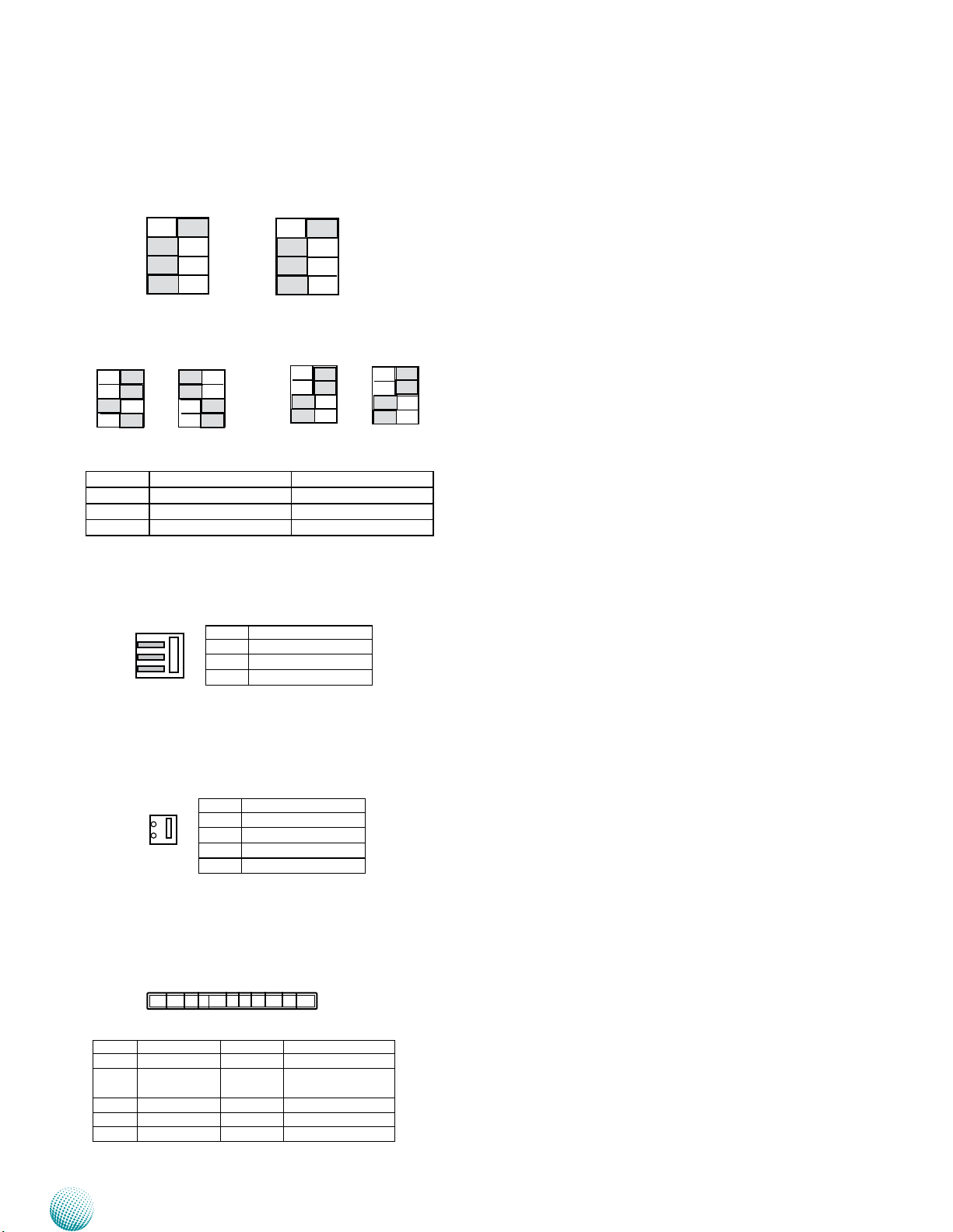
MCU (Microcontroller) Function Selection (SW1, SW2):
It is for selecting the microcontroller’s function.
SW1
1
2
3
4
ON
SW2
1
2
3
4
ON
Board Layout
Download Data
1
2
3
4
ON
Jumper Pin No. Pin NO.
SW1 1-ON, 2-ON, 3-OFF, 4-ON 1-ON, 2-ON, 3-OFF, 4-OFF
SW2 1-OFF, 2-OFF, 3-ON, 4-ON 1-ON, 2-ON, 3-OFF, 4-OFF
Function Download Data Normal (Default)
1
2
3
4
ON
Normal (Default)
1
2
3
4
ON
1
2
3
4
ON
An external RS-232 connector for MCU programming
(CN1)
1
2
3
Pin No. Pin Name
1 EXT_TXD_R
2 GND
3 EXT_RXD_R
IGN_CON1
4
3
2
1
Pin No. Pin Name
1 REMOTE_POWER_ON
2 3G_POWER_ON
3 IGN_DI0
4 IGN_DI1
Ignition Control Connector (IGNITION1)
10 9 8 7 1
Pin No. Pin Name Pin No. Pin Name
1 IGNITION 6 D2D_EN
2 SYS_POWER_
SWITCH
3 COM_SOUT 8 GND
4 COM_SIN 9 DC_VIN
5 D2D_PWROK 10 DCIN_VCC
Embedded and Industrial Computing
7 SYS_POWER_OK
27
Page 28
Chapter 4
Chapter 4:
The Flow Chart
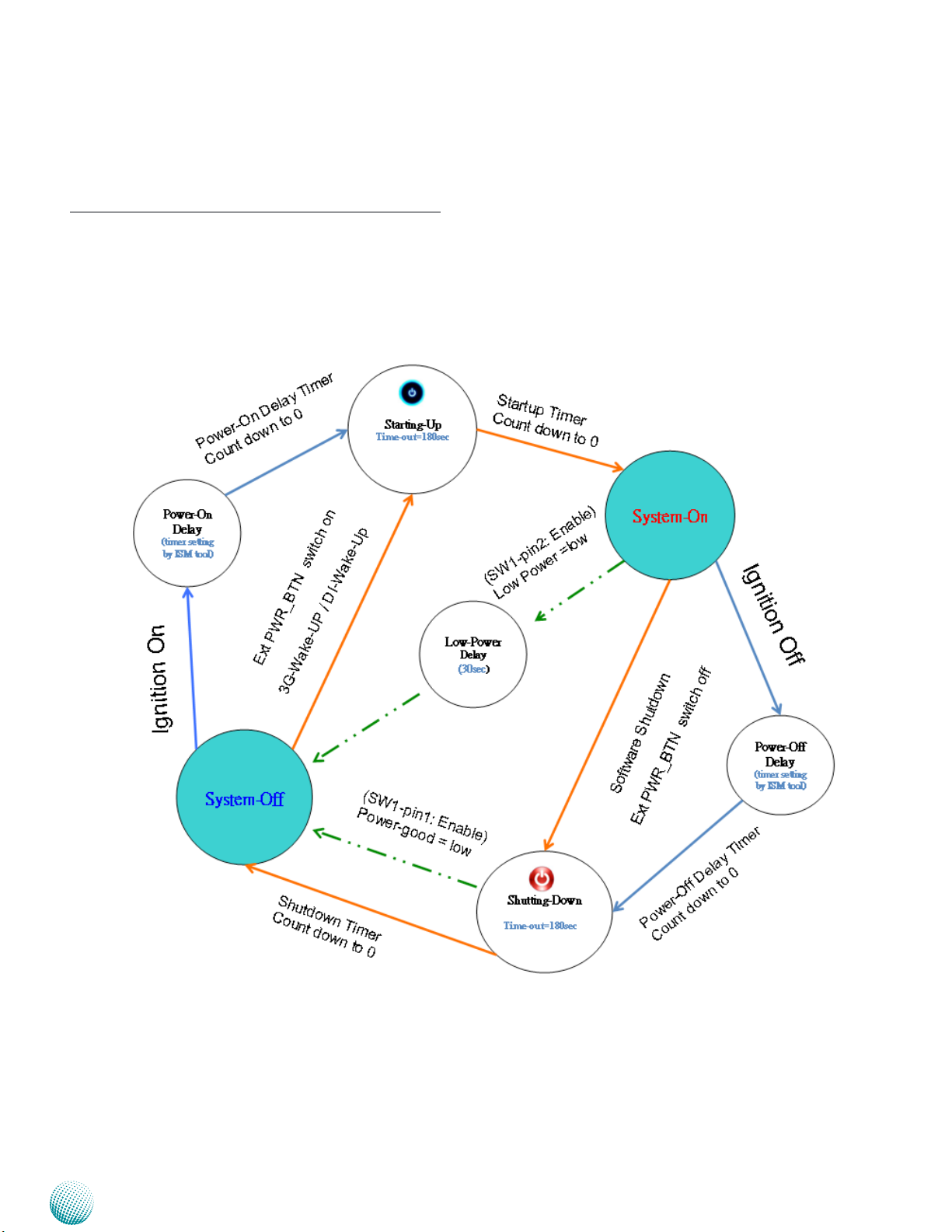
The flow chart section contains all flow chart used in the
system. The flow chart describes the system’s behavior on
powering on and off the system via power ignition control
or on/off switch when the appropriate timer control
parameters are set.
Flow Chart
Note:
1.
For power-good and low-voltage
mechanism to function in the workflow,
you will need to enable the power-good
and low-voltage detection function
with selector 1 and selector 2 jumper
respectively of SW1 on LEK-IG1 board.
(Refer to Chapter 3 Board Layout).
Embedded and Industrial Computing
For power on and power off delay timer 2.
parameter, refer to Appendix A Using the
Ignition System Manager (ISM).
For 3G wake-up and DI wake-up 3.
function, refer to jumper MCARD1(MiniPCIe) and J3 (DIO) respectively. Refer to
Chapter 3 Board Layout and Appendix
A Using the Ignition System Manager
(ISM) for jumper setting and parameter
setting.
When the system’s shutdown timer starts 4.
counting down 180sec, using ignition
or External PWR_BTN to start the system
again during shutdown process will not
work until the countdown finishes.
28
Page 29
Chapter 5
Hardware Setup
Chapter 5:
Hardware Setup
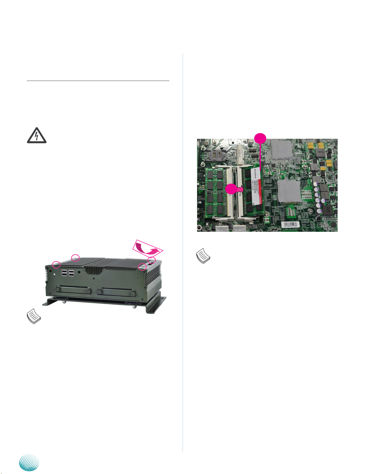
Preparing the Hardware Installation
To access some components and perform certain service
procedures, you must perform the following procedures
first.
WARNING: To reduce the risk of personal injury,
electric shock, or damage to the equipment,
remove the power cord to remove power from
the server. The power switch button does not
completely shut off system power. Portions of the
power supply and some internal circuitry remain
active until power is removed.
Unpower the LVC-5570 and remove the power cord.1.
Unscrew the 4 threaded screws from the top cover.2.
Open the cover.3.
Installing the System Memory
The motherboard supports DDR3 memory to meet the
higher bandwidth requirements of the latest operating
system and Internet applications. It comes with two
Double Data Rate Three (DDR3) Small Outline Dual Inline
Memory Module (SO-DIMM) socket.
Align the memory module’s key with the SO-DIMM 1.
socket’s key.
Install the SO-DIMM.2.
2
1
Note:
If the CPU thermal pad mounting breaks apart,
use your hands to reattach the falling parts and
stick them together.
Note:
The system can support memory of DDR3 SODIMM up to 16 GB in maximum with 2 SO-DIMM
sockets.
Embedded and Industrial Computing
29
Page 30
Chapter 5
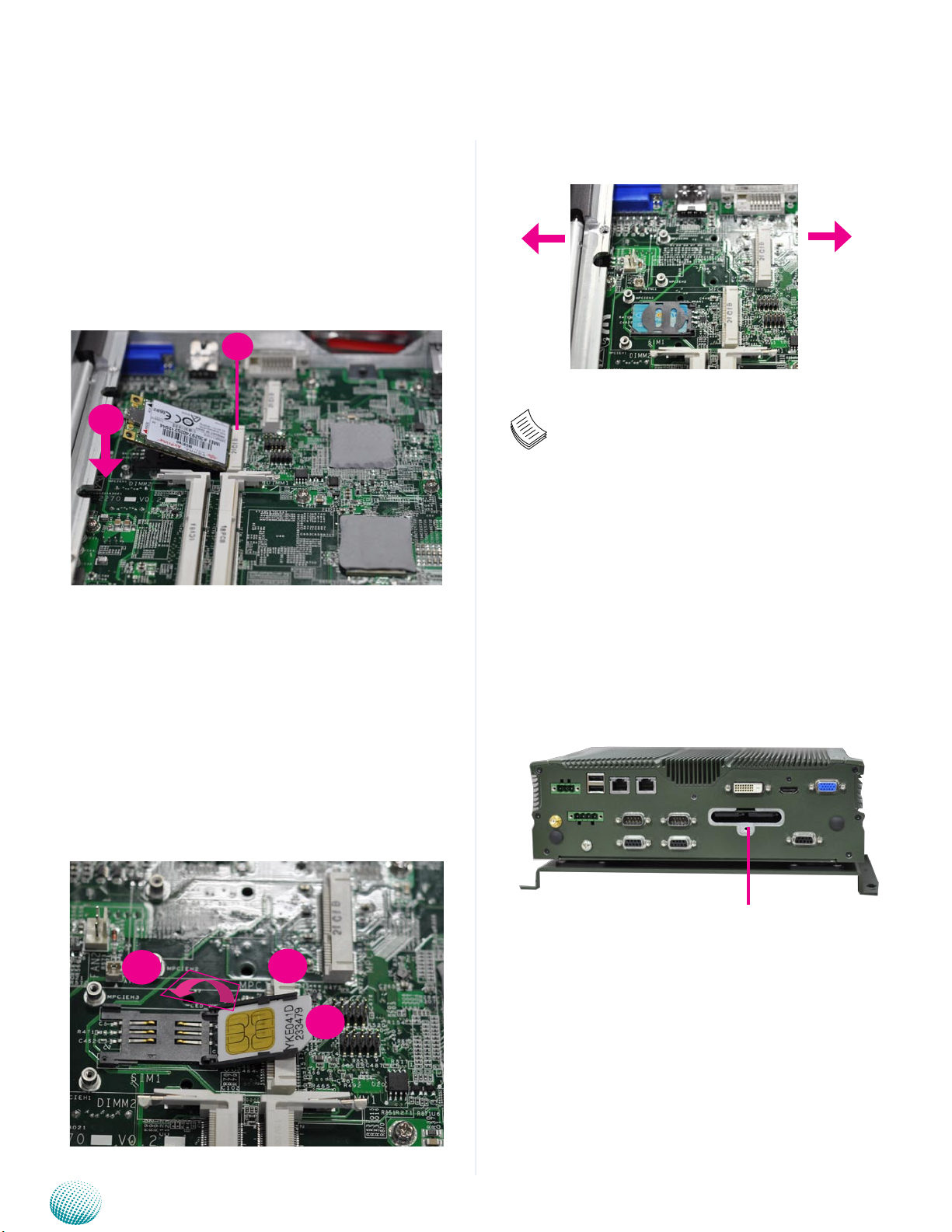
Wireless Module Installation
Align the wireless module’s cutout with the Mini-PCIe 1.
slot notch.
Insert the wireless module into the connector 2.
diagonally.
Hold down the other end of the wireless module and 3.
tighten it with the screws.
2
Lock
Hardware Setup
Unlock
3
3G SIM Card Installation
Unlock the SIM card reader first by sliding it outward.1.
Flip the SIM card reader diagonally.2.
Align the angled corner of the SIM card pointing 3.
toward SIM card reader. Make sure the ICs will be in
contact with the SIM card reader.
Insert the 4. SIM card into the reader and close the tray.
You should feel a click when the SIM card is locked
securely in the SIM card reader.
Note: To remove the SIM card, slide the card
reader outward to unlock it.
External SIM Card Installation
Take out the SIM Card tray by pushing the ejector with 1.
a pointed object.
Place the SIM card on the SIM card tray. Notice the 2.
angled corner to align the SIM card properly.
4
Embedded and Industrial Computing
ejector
(SIM2 SIM1)
2
3
30
Page 31
Chapter 5
IG - +
DC IN
DC_IN
IGNITION
LVC-5570
DC_GND
Hardware Setup
Installing the Hard Disk
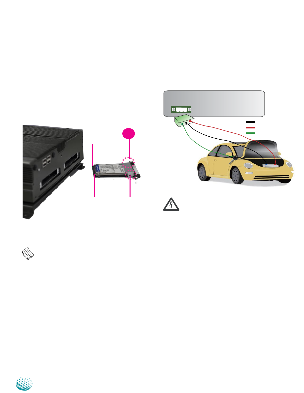
The system can accommodate two Serial-ATA disk. Follow
these steps to install the hard disk into the system:
Place the HDD/SSD on the hard disk tray of the front 1.
panel and align the holes of the hard disk with the
mounting holes on the tray.
Fix the HDD/SSD on the hard disk tray by using 2 2.
mounting screws
Push the HDD/SSD into the hard disk slot and secure it 3.
in place with the thumb screws.
1
Drive Connector
Connecting Power
Connect the LVC-5570 to a +12V or +24V vehicle battery.
The DC power-in connector comes with a 3-pin terminal
block for its Phoenix contact. This power socket can only
accept the power supply with the right pin contact so be
cautious when inserting power to the system.
Power Connector
Note:
The system only supports 2.5” HDD/SSD.1.
Make sure that you insert the HDD in 2.
the right orientation (shown as the
above picture) to prevent damage to the
connectors. Do not force the HDD into the
slot; it indicates wrong orientation if the
insertion is not smooth.
Silver plate
Warning:
Connect the power to the DC-IN connector in the
right orientation or the LVC-5570 will be damaged.
Embedded and Industrial Computing
31
Page 32
Appendix A
Appendix A:
Using the Ignition System
Manager (ISM)
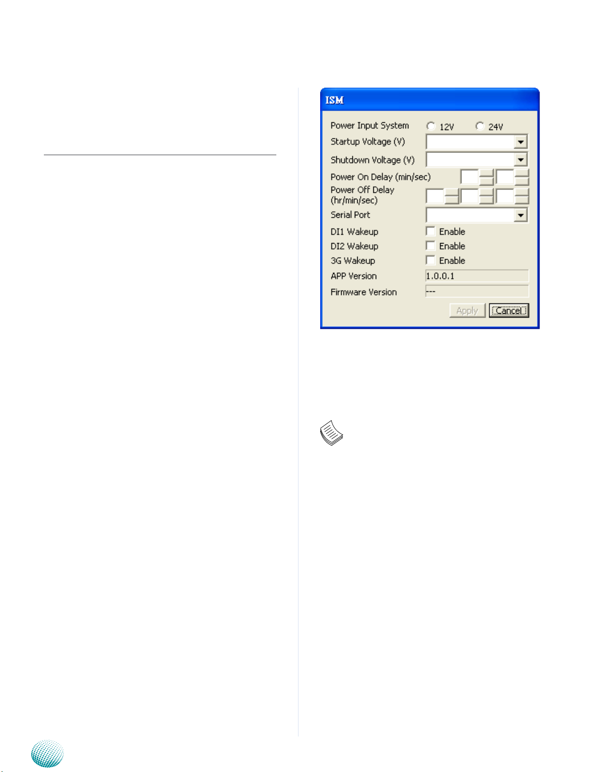
The Ignition System Manager (ISM) is a software that
can monitor the system’s voltage level and configure the
features that the Power Ignition Module provides.
Using the Ignition System Manager (ISM)
For sample ISM code, see ISM folder under LVC-5570 Utility
on the Driver and Manual CD.
Running the Program
Just double click the ISM.exe to launch the ISM.
The program can configure the following values:
Voltage: It shows the current power system.
Power Input System: Select either 12V or 24V for vehicular
power input.
Startup Voltage (V): If the DC-in voltage is not higher
than this value, the system will not be able to start up.
Shutdown Voltage (V): If the DC-in voltage is lower than
the shutdown voltage, the system will start shutdown
process automatically. (Refer to selector 2 of SW1 dip
switch on the LEK-IG1 board)
Power-on Delay (min/sec): Select power-on delay value
to indicate the time to delay powering on the system.
(Refer to the flow chart in Chapter 4)
Power-off Delay (hr/min/sec): Select power-off delay
value to indicate the time to delay powering off the system
(Refer to the flow chart in Chapter 4)
Serial Port: Select the serial communication port for the
ISM. Choose COM5.
D1/D2 Wakeup: Digital input triggering to enable
automatic wake-up function. Select this option and it will
start the system automatically once an input has been
triggered.
COM5
Note:
You will have to enable (the default is enabled) 1.
the selector 2 (Low Voltage Detection) of SW1
dip switch on the LEK-IG1 to enable automatic
shutdown function. (Refer to Select MCU Detect
Function for power ignition behavior (SW1) in
Chapter 3 Board Layout).
DI1/DI2 Wakeup function is detected via pin 2.
12/13 of J3 (DIO)
3G Wake-up function is enabled via MCARD1 3.
Mini-PCIe connector.
Refer to the flow charts in Chapter 4 for more 4.
information.
3G Wakeup: 3G SMS/Ring wake-up to enable automatic
wake-up function. Select this option and it will start the system
automatically through 3G internet service.
After you have made changes, click Apply to apply the
changes to the Ignition controller or Cancel to cancel the
changes.
Click Cancel to exit the ISM program.
Embedded and Industrial Computing
.
32
Page 33
Appendix B
Digital Input/Output Control
Appendix B:
Digital Input/Output
The Digitanl I/O on the rear panel is designed to provide
the input and output operations for the system. For sample
DIO code, see SuperIO folder under LVC-5570 Utility on the
Driver and Manual CD. Make sure that you have installed
the Lanner GPIO driver as instructed below.
Driver Installation
Before you could access or control the operation of the
G-sensor, GPS and Digital I/O functions, install the the L_
IO driver which is the library and driver needed for Lanner
General Purpose Input/Output interface or functions.
To install the L_IO driver:
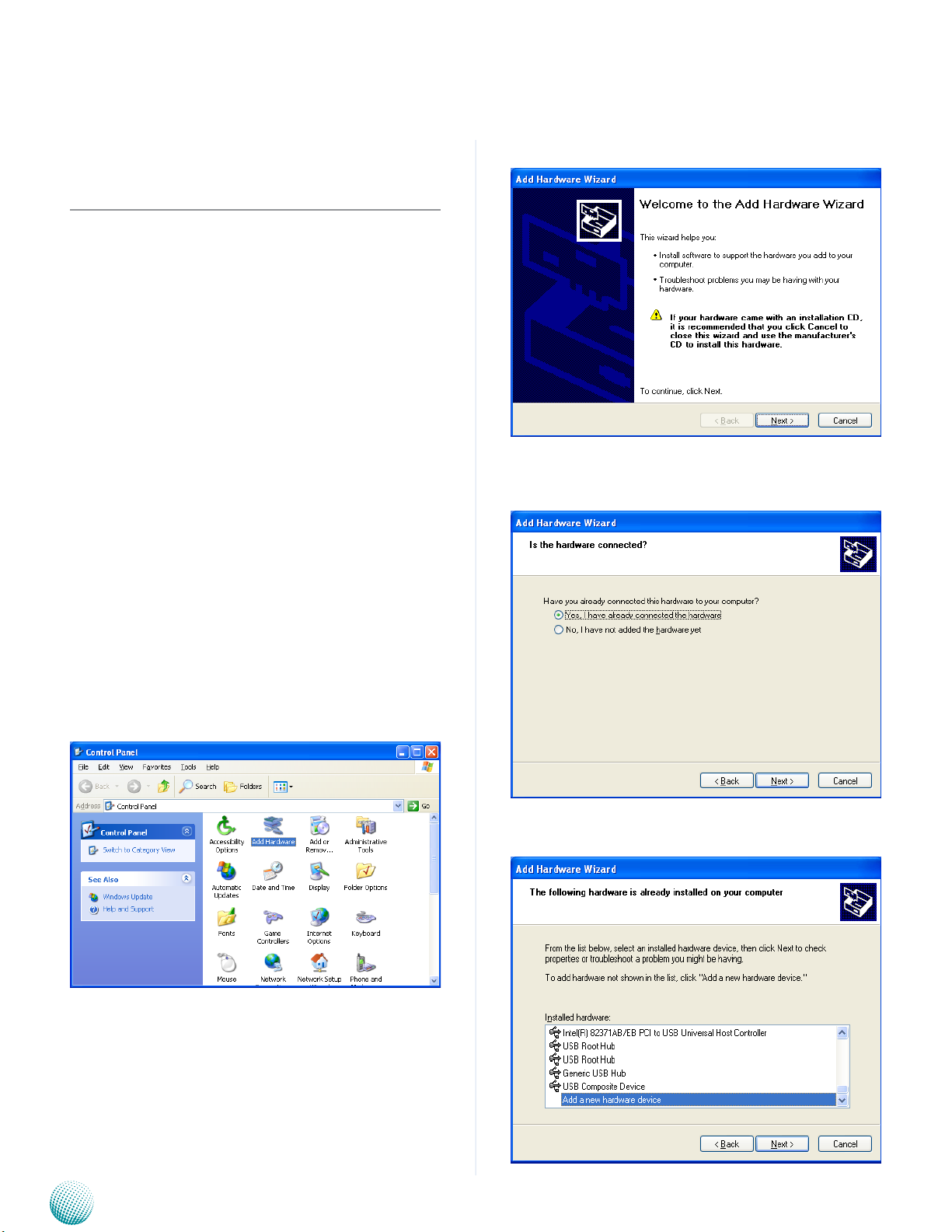
Restart the computer, and then log on with 1.
Administrator privileges.
Insert the Drivers and User’s Manual CD to the USB-2.
optical drive.
Select Next to proceed5.
Answer “Yes” to the question and select Next to 6.
proceed.
Browse the contents of the support CD to locate the 3.
file in the LIO folder.
From the control panel, click the ADD Hardware 4.
program
Select Add a new hardware device.7.
Embedded and Industrial Computing
33
Page 34
Appendix B
Digital Input/Output Control
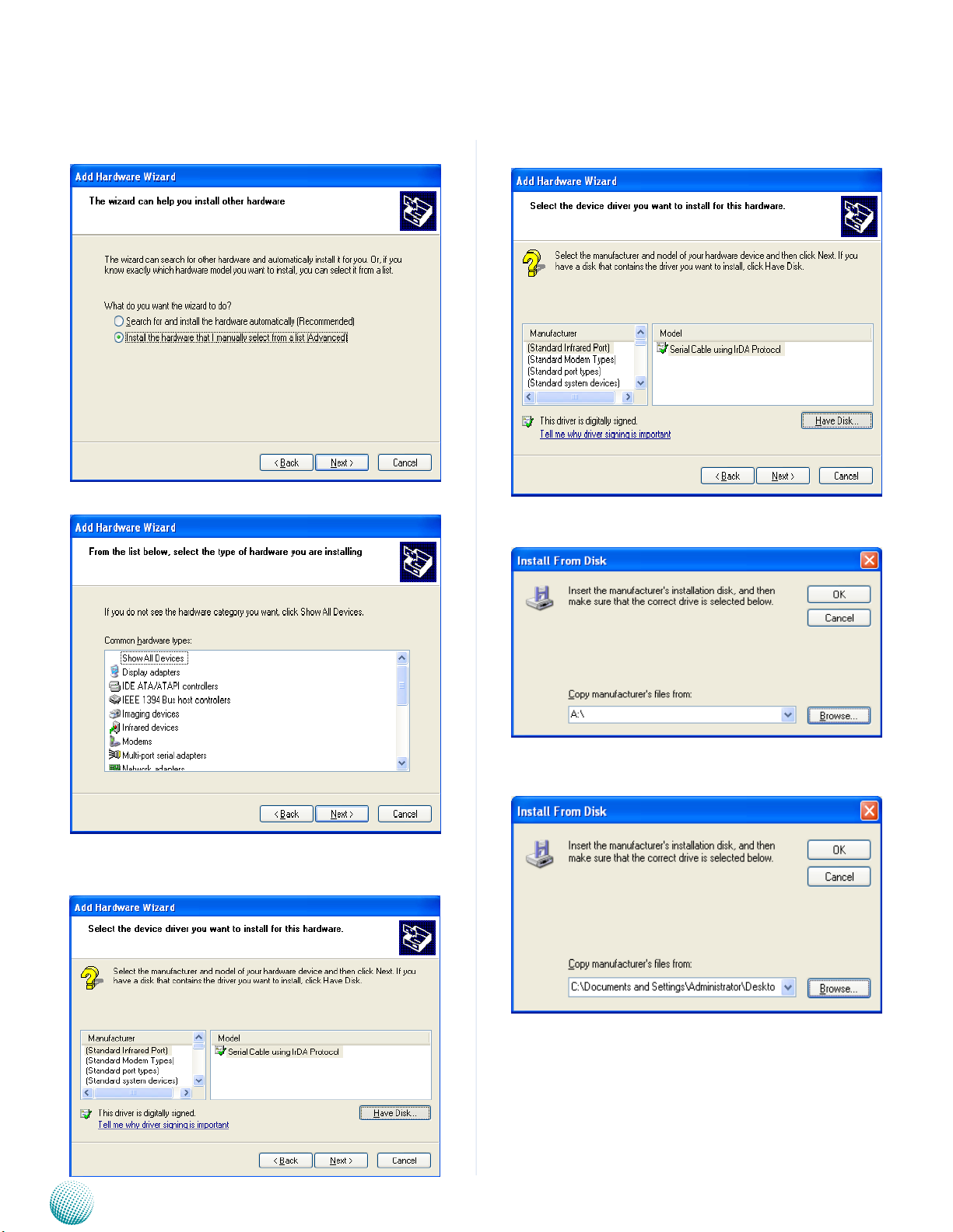
Choose to select the hardware Manually8.
Choose Show all device and click Next.9.
Click HaveDisk to locate the L_IO.inf file11.
Select the L_IO.inf12.
Click HaveDisk to locate the L_IO.inf file10.
Embedded and Industrial Computing
Select OK to confirm with the installation13.
34
Page 35
Appendix B
Digital Input/Output Control
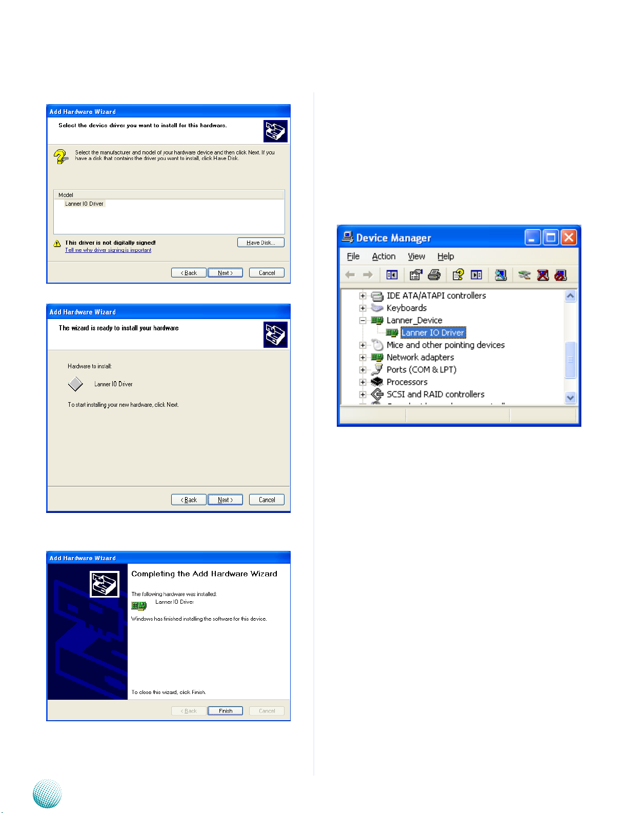
Select the Lanner IO driver and click Next.14.
Click Next15.
To verify the GPIO driver installation, do the following
steps:
Right-click on the My Computer icon, and then select 1.
Properties form the menu.
Click the Hardware tab, then click the Device Manager 2.
button.
Click the + sign next to the Lanner_Device, then the 3.
Lanner IO Driver should be listed.
Click 16. Complete to close the installation program.
Embedded and Industrial Computing
35
Page 36

Appendix B
A sample DIO program in C:
ioaccess.c: IO access code for Lanner Platfomr Digital IO
program
*********************************************************
**********************/
Digital Input/Output Control
#include <time.h>
#include <stdint.h>
#include <fcntl.h>
#include <errno.h>
#include <string.h>
#include “../include/config.h”
#ifdef DJGPP
/* standard include file */
#include <stdio.h>
#include <stdlib.h>
#include <unistd.h>
/* For DOS DJGPP */
#include <dos.h>
#include <inlines/pc.h>
#else //DJGPP
/* For Linux */
#define delay(x) usleep(x)
#endif
#ifdef MODULE
#include <linux/kernel.h>
#include <linux/module.h>
#include <linux/kernel.h>
#include <linux/fs.h>
#include <asm/io.h>
#include <linux/delay.h>
#undef delay
#define delay(x) mdelay(x)
#undef fprintf
#define fprintf(S, A) printk(A)
#ifdef DIRECT_IO_ACCESS
/* For Linux direct io access code */
/* standard include file */
#include <stdio.h>
#include <stdlib.h>
#include <unistd.h>
#if defined(LINUX_ENV)
#include <sys/io.h>
#endif
#if defined(FreeBSD_ENV)
#include <machine/cpufunc.h>
#endif
Embedded and Industrial Computing
#endif //MODULE
#ifdef KLD_MODULE
#include <sys/types.h>
#include <sys/param.h>
#include <sys/systm.h>
#include <sys/malloc.h>
#include <sys/kernel.h>
#include <sys/bus.h>
#include <sys/errno.h>
36
Page 37

Appendix B
Digital Input/Output Control
#include <machine/bus.h>
#include <machine/resource.h>
#endif
#endif
/* local include file */
#include “../include/ioaccess.h”
#if (defined(MODULE) || defined(DIRECT_IO_ACCESS) ||
defined(KLD_MODULE))
/*
*---------------------------------------------------------------------------
---
* LEB-5570 Version V1.0
*output3-0 = GPIO 03-00, input3-0= GPIO 53-50
*---------------------------------------------------------------------------
--------
outportb(INDEX_PORT, 0xAA);
return;
}
unsigned char read_SIO_reg(int LDN, int reg)
{
outportb(INDEX_PORT, 0x07); //LDN register
delay(5);
outportb(DATA_PORT, LDN);
delay(5);
outportb(INDEX_PORT, reg);
delay(5);
return(inportb(DATA_PORT));
}
void write_SIO_reg(int LDN, int reg, int value)
{
*/
/*
* Device Depend Definition :
*/
#define INDEX_PORT 0x2E
#define DATA_PORT 0x2F
void enter_SIO_config(void)
{
outportb(INDEX_PORT, 0x87); // Must Do It Twice
outportb(INDEX_PORT, 0x87);
return;
}
void exit_SIO_config(void)
{
outportb(INDEX_PORT, 0x07); //LDN register
delay(5);
outportb(DATA_PORT, LDN);
delay(5);
outportb(INDEX_PORT, reg);
delay(5);
outportb(DATA_PORT, value);
return;
}
void dio_gpio_init(void)
{
enter_SIO_config();
write_SIO_reg(0x6, 0x30,0x01); //enable GPIO
Port
write_SIO_reg(0x6, 0xf0,((read_SIO_reg(0x6,
0xf0)& 0xF0)|0x0f)); //RxF0[3-0]=1111b, output
write_SIO_reg(0x6, 0xA0, (read_SIO_reg(0x6,
0xA0)& 0xF0)); //RxA0[3-0]=0000b, input
Embedded and Industrial Computing
37
Page 38

Appendix B
exit_SIO_config();
return;
}
void dio_set_output(unsigned char out_value)
{
enter_SIO_config();
write_SIO_reg(0x6, 0xf1, ((read_SIO_reg(0x6,
0xf1)& 0xF0)|out_value));
exit_SIO_config();
return;
}
unsigned int dio_get_input(void)
{
Digital Input/Output Control
unsigned int tmp=0x00;
enter_SIO_config();
tmp=read_SIO_reg(0x6, 0xA2)& 0x0f;
exit_SIO_config();
return tmp;
}
//======================================
========================================
=================
#endif
Embedded and Industrial Computing
38
Page 39

Appendix C
Accessing the Digital Accelerometer
Appendix C:
Accessing the Digital
Accelerometer Data from
the LVC-5570
The system employs Analog Devices’s ADXL345 Digital
Accelerometer which is a small, thin, ultralow power, 3-axis
accelerometer with high resolution (13-bit) measurement
at up to ±16 g. It interfaces with the LVC-5570 through a
SPI interface.
Driver Installation
To access the G-Sensor data, use the following
instructions:
Make sure you already installed the Lanner GPIO driver on
your LVC-5570 as instructed in Appendix B.
To access the Gsensor data, locate the adxl345_v001 folder
and execute the executable file adxl345 and it will show G
value of 3 axes.
A sample program in C:++
// main.cpp
// The adxl345.exe utility shows the 3 axis G value.
//
// History:
// 07/15/2011: Initial version
#include <winsock2.h>
#include <windows.h>
#include <stdio.h>
#include “ich7.h”
#include “adxl345.h”
void adxl345_init()
{
ich7_SM_WriteByte (0x1D, POWER_CTL, ACT_INACT_
SERIAL | MEASURE) ; // Power CTL:
Measure mode, Activity and Inactivity Serial
ich7_SM_WriteByte (0x1d, BW_RATE, RATE_100);
/ /
Output Data Rate: 100Hz
ich7_SM_WriteByte (0x1d, DATA_FORMAT, FULL_
RESOLUTION | DATA_JUST_LEFT | RANGE_16G);
/ /
Data Format: 16g range, right justified, 256->1g
}
Embedded and Industrial Computing
int main(int argc, char* argv[])
{
adxl345_init () ;
39
Page 40

Appendix C
while (1)
{
short x = (short) ich7_SM_ReadByte
(0x1d, DATAX1) << 8 | ich7_SM_ReadByte (0x1d,
DATAX0)<<0 ;
short y = (short) ich7_SM_ReadByte
(0x1d, DATAY1) << 8 | ich7_SM_ReadByte (0x1d,
DATAY0)<<0 ;
short z = (short) ich7_SM_ReadByte
(0x1d, DATAZ1) << 8 | ich7_SM_ReadByte (0x1d,
DATAZ0)<<0 ;
printf (“\rX=%.2f Y=%.2f Z=%.2f”, ((float)
x)/2048,((float)y)/2048,((float)z)/2048) ;
}
Accessing the Digital Accelerometer
}
Embedded and Industrial Computing
40
Page 41
Appendix D
Accessing the GPS Data
Appendix D:
Accessing the GPS Data
from the LVC-5570
The LVC-5570 employs an onbard u-blox NEO-6Q GPS
module for vehicle tracking and navigation system. You
could read the GPS data through the RS-232 serial port.
It has the following listed key features and performance
ratings:
Receiver type 50 Channels
GPS L1 frequency, C/A Code
SBAS: WAAS, EGNOS, MSAS
Time-To-First-Fix (All satellites at -130 dBm)
Sensitivity Tracking &Navigation: •
Maximum Navigation
update rate
Horizontal position accurach (CEP, 50%, 24 hours
static, -130dBm, SEP:
<3.5m)
Congurable Timepulse
frequency range
Accuracy for Timepulse
signal
Velocity accuracy 0.1m/s
Heading accuracy 0.5 degrees
Operational Limits Dynamics: less than and
Cold Start: 26 s
Warm Start: 26 s
Hot Start: 1 s
Aided Starts: 1 s
-162dBm
Reacquisition: -160dBm•
Cold Start (without aid-•
ing): -148 dBm
Hot Start: -157 dBm•
5Hz
GPS: 2.5m
SBAS: 2.0m
0.25 Hz to 1 kHz
RMS: 30 ns
99%: <60 ns
Granularity: 21 ns
Compensated: 15 ns
equal to 4g
Altitude: 50,000m
Velocity: 500m/s (Assuming
Airborne <4g platform)
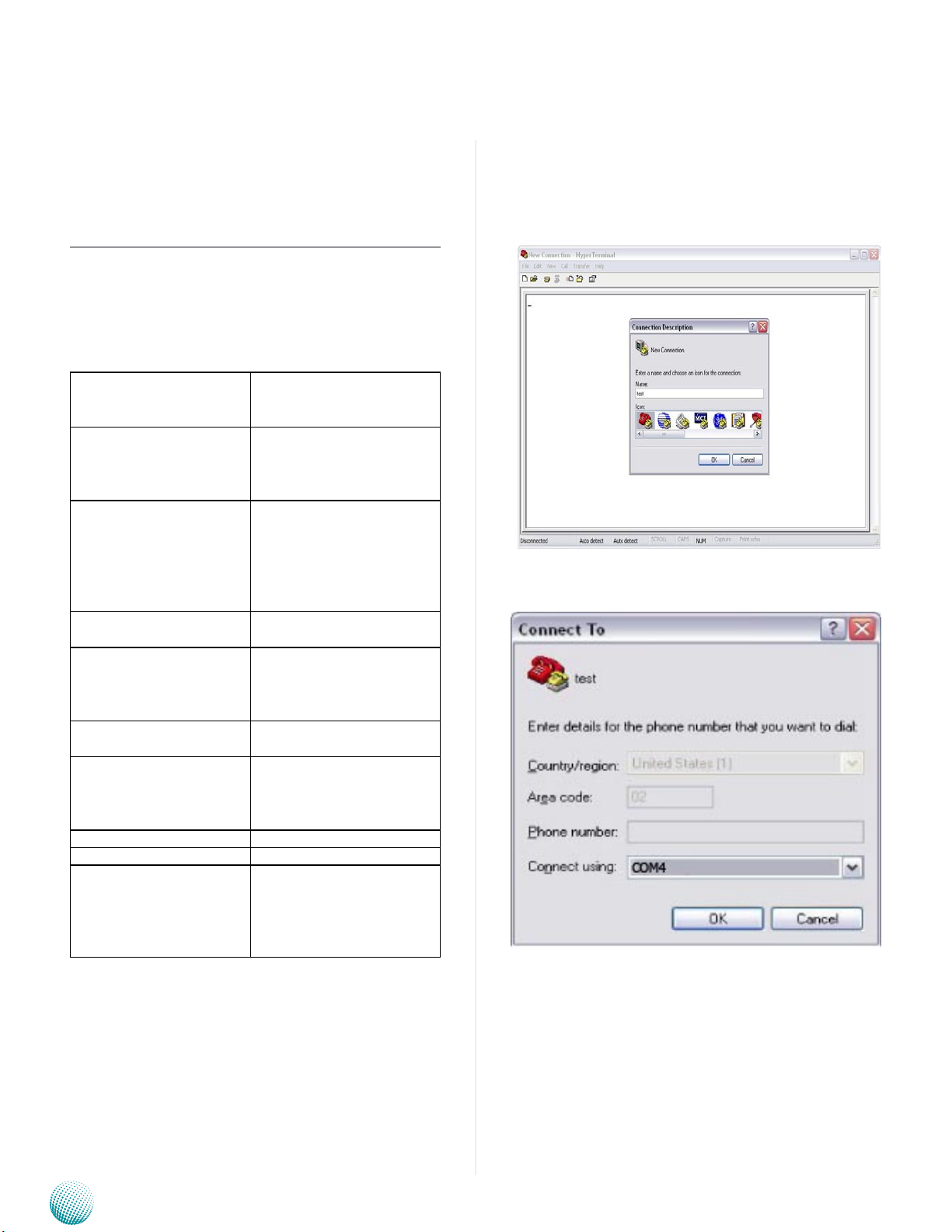
To access the GPS data, follow the following steps:
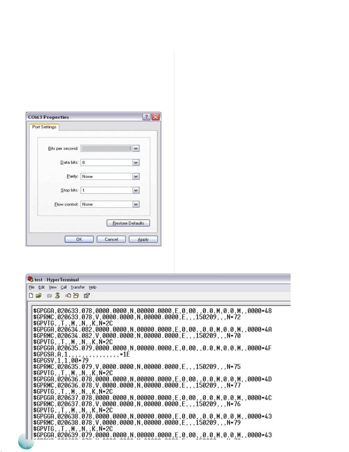
Select Programs from the Start menu on your windows
and open the Hyper Terminal program.
Choose COM4 from the Connection using drop-down
menu:
Embedded and Industrial Computing
41
Page 42
Appendix D
Specify the following communication parameters:
Bits per Second: 9600
Data Bits: 8
Parity: None
Stop Bit: 1
Flow Control: None
9600
Accessing the GPS Data
The hyper terminal should display GPS data:
Embedded and Industrial Computing
42
Page 43
Appendix E
Programming Watchdog Timer
Appendix E:
Programming System
Watchdog Timer of the
LVC-5570
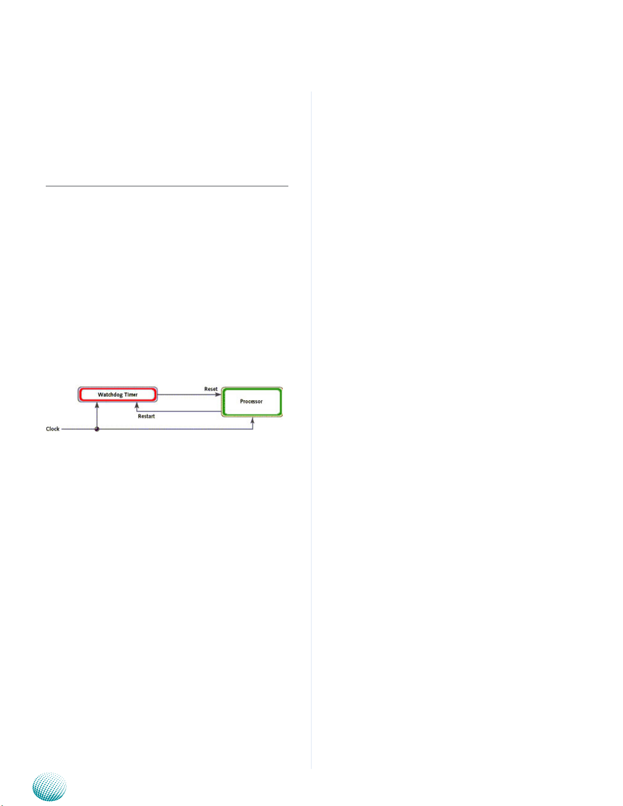
A watchdog timer is a piece of hardware that can be
used to automatically detect system anomalies and reset
the processor in case there are any problems. Generally
speaking, a watchdog timer is based on a counter that
counts down from an initial value to zero. The software
selects the counter’s initial value and periodically restarts
it. Should the counter reach zero before the software
restarts it, the software is presumed to be malfunctioning
and the processor’s reset signal is asserted. Thus, the
processor will be restarted as if a human operator had
cycled the power.
For sample watchdog code, see watchdog folder under
LVC-5570 Utility on the Driver and Manual CD
#include “F81865.h”
#define PARAMETER_HELP “\n”\
“The F81865 GPIO utility of Lanner\n”\
“-------------------------------------\n”\
“Usage:\n”\
“ F81865_test DIO_IN port_
number\n”\
“ F81865_test DIO_OUT port_number
value\n”\
“ F81865_test PIO port_number
value\n”\
“ F81865_test RunLED port_number
value\n”\
“ F81865_test AlarmLED port_number
value\n”\
“ F81865_test GPS_LED port_number
value\n”\
Executing through the Command Line:
Execute the WD.EXE file under DOS (WD.EXE and CWSDPMI.
EXE should be placed on same directory), then enter the
values from 0~255. The system will reboot automatically
according to the time-out you set.
/////////////////////////////////////////////////////////
You can write your own program by modifying the source
code F81865_Test.cpp.. The index address is 2EH.
/////////////////////////////////////////////////////////////////////
////
// F81865_Test.cpp : F81865_test.exe utility for F81865.lib
APIs demonstration.
//
// History:
// 7/15/2011 Brand new F81865_test
program.
“ F81865_test WirelessLED port_number
value\n”\
“ F81865_test WatchDog seconds\n”\
“ F81865_test CaseOpen\n”\
“ F81865_test CaseOpen_Clear\n”\
“ F81865_test Sleep
milliseconds\n”\
“\n”\
“Argement:\n”\
“ DIO_IN Read state from DIO
In.\n”\
“ DIO_OUT Set DIO Out state.\n”\
“ PIO Set PIO LED state.\n”\
“ RunLED Set RUN LED state.\n”\
“ AlarmLED Set Alarm LED state.\n”\
#include <winsock2.h>
#include “Windows.h”
#include “stdio.h”
Embedded and Industrial Computing
“ GPS_LED Set GPS LED state.\n”\
“ WirelessLED Set Wireless LED state.\n”\
43
Page 44

Appendix E
Programming Watchdog Timer
“ Watchdog Set
Watchdog timer.\n”\
“ CaseOpen Check case opened state.\n”\
“ CaseOpen_Clear Clear case open state.\n”\
“ port_number The port number.\n”\
“ value 1 for on and 0 for off.\n”\
“ seconds The
watchdog count down seconds. 0 for disable.\n”\
“ milliseconds Milliseconds to
delay\n”
#define RETMSG(a,b) {printf (b) ; return a;}
#define CHECK_ARGC(a) {if (argc
!= a) throw PARAMETER_HELP ;}
// Translate Hex string to a long value
LONG Hex2Long (char *str)
{
LONG nLong ;
if (scanf (str, “%x”, &nLong) != 1)
throw “Error parsing parameter\n” ;
return nLong ;
}
// Make sure the argument is numeric
void CheckNumeric (char *szBuf)
{
int nLen = strlen (szBuf) ;
for (int i = 0 ; i < nLen ; i++)
if (!strchr (“01234567890ABCDEFabcdef”, szBuf[i]) )
throw “Wrong argument\n” ;
}
// Common GPIO output function definition
#define GPIO_OUT(a,b,c) \
int a (int argc, char *argv[]) \
{
\
CHECK_ARGC (4) ;
\
\
int nPort = atoi (argv[2]) ; \
int nValue = atoi (argv[3]) ; \
\
c (nPort, nValue) ;
\
\
printf (b “ #%d = %d\n”, nPort, nValue) ; \
\
return 0
; \
}
// Function generate by common function definition
GPIO_OUT (mDIO_
OUT , “DIO_OUT” , Write_DIO)
G P I O _ O U T
(mPIO , “DIO_OUT” , PIO)
G P I O _ O U T
(mRunLED , “RunLED” , RunLED)
G P I O _ O U T
(mAlarmLED , “AlarmLED” , AlarmLED)
GPIO_OUT (mGPS_
LED , “GPS_LED” , GPS_LED)
G P I O _ O U T
(mWirelessLED , “WirelessLED” , WirelessLED)
// Check case open
int mCaseOpen (int argc, char* argv[])
{
CHECK_ARGC (2) ;
BOOL bOpen = CaseOpen () ;
printf (“Case is %s\n”, bOpen ? “Open” : “Close”) ;
return bOpen ;
}
CheckNumeric (argv[2]) ; \
CheckNumeric (argv[3]) ; \
Embedded and Industrial Computing
44
Page 45

Appendix E
Programming Watchdog Timer
// Clear case open state
int mCaseOpen_Clear (int argc, char* argv[])
{
CHECK_ARGC (2) ;
CaseOpen_Clear () ;
BOOL bOpen = CaseOpen () ;
printf (“CaseOpen state %s”, bOpen ? “not cleared”
: “cleared”) ;
return bOpen ;
}
// Get DIO_IN state
int mDIO_IN (int argc, char* argv[])
{
CHECK_ARGC (3) ;
CheckNumeric (argv[2]) ;
return 0 ;
}
// Watchdog
int mWatchDog (int argc, char *argv[])
{
if (argc != 3 && argc != 2)
RETMSG (-1, PARAMETER_HELP) ;
if (argc == 3)
{
CheckNumeric (argv[2]) ;
int nValue = atoi (argv[2]) ;
WatchDog_Enable (nValue) ;
}
int nLeft = WatchDog_GetLeft () ;
int nPort = atoi (argv[2]) ;
BOOL ret = Read_DIO (nPort) ;
printf (“DIO_IN #%d = %d\n”, nPort, ret) ;
return ret ;
}
// Milli-second delay
int mSleep (int argc, char *argv[])
{
CHECK_ARGC (3) ;
CheckNumeric (argv[2]) ;
Sleep (atoi (argv[2]) ) ;
printf (“Watchdog timer left %d seconds\n”, nLeft)
;
return nLeft ;
}
// Argument - function mapping
typedef struct
{
char *szCmd ;
int (*function) (int argc, char *argv[]) ;
} CMD2FUN ;
CMD2FUN c2f[] =
{
Embedded and Industrial Computing
45
Page 46

Appendix E
{“DIO_IN” , mDIO_IN
},
{“DIO_OUT” , mDIO_OUT
},
{“PIO” , mPIO
},
{“RunLED” , mRunLED
},
{“AlarmLED” , mAlarmLED
},
{“GPS_LED” , mGPS_LED
},
{“WirelessLED” , mWirelessLED },
{“CaseOpen” , mCaseOpen },
{“CaseOpen_Clear”,mCaseOpen_Clear},
{“Watchdog” , mWatchDog
},
Programming Watchdog Timer
// No match argument
RETMSG (-1, “Wrong Argument\n”) ;
}
catch (char *str)
{
// Output the error message
printf (“\n%s\n”, str) ;
}
catch (...)
{
// Unknown exception
printf (“\nUnknown Exception\n”) ;
}
{“Sleep” , mSleep }
} ;
// Program start here
int main(int argc, char *argv[])
{
try
{
// The total argument allowed
int num = sizeof (c2f ) / sizeof (c2f[0]) ;
// Too few argument
if (argc < 2)
RETMSG (-1, PARAMETER_HELP)
;
return -1 ;
}
// Find the match argument and execute
the mapping function
for (int i = 0 ; i < num ; i++)
if (stricmp (argv[1], c2f[i].szCmd)
== 0)
return c2f[i].function
(argc, argv) ;
Embedded and Industrial Computing
46
Page 47

Appendix F
Terms and Conditions
Appendix F:
Terms and Conditions
Warranty Policy
All products are under warranty against defects in 1.
materials and workmanship for a period of one year
from the date of purchase.
The buyer will bear the return freight charges for 2.
goods returned for repair within the warranty period;
whereas the manufacturer will bear the after service
freight charges for goods returned to the user.
The buyer will pay for repair (for replaced components 3.
plus service time) and transportation charges (both
ways) for items after the expiration of the warranty
period.
If the RMA Service Request Form does not meet the 4.
stated requirement as listed on “RMA Service,” RMA
goods will be returned at customer’s expense.
The following conditions are excluded from this 5.
warranty:
RMA Service
Requesting a RMA#
To obtain a RMA number, simply fill out and fax the 6.
“RMA Request Form” to your supplier.
The customer is required to fill out the problem code 7.
as listed. If your problem is not among the codes listed,
please write the symptom description in the remarks
box.
Ship the defective unit(s) on freight prepaid terms. 8.
Use the original packing materials when possible.
Mark the RMA# clearly on the box. 9.
Note: Customer is responsible for shipping
damage(s) resulting from inadequate/loose
packing of the defective unit(s). All RMA# are valid
for 30 days only; RMA goods received after the
effective RMA# period will be rejected.
Improper or inadequate maintenance by the customer
Unauthorized modification, misuse, or reversed
engineering of the product Operation outside of the
environmental specifications for the product.
Embedded and Industrial Computing
47
Page 48
Appendix F
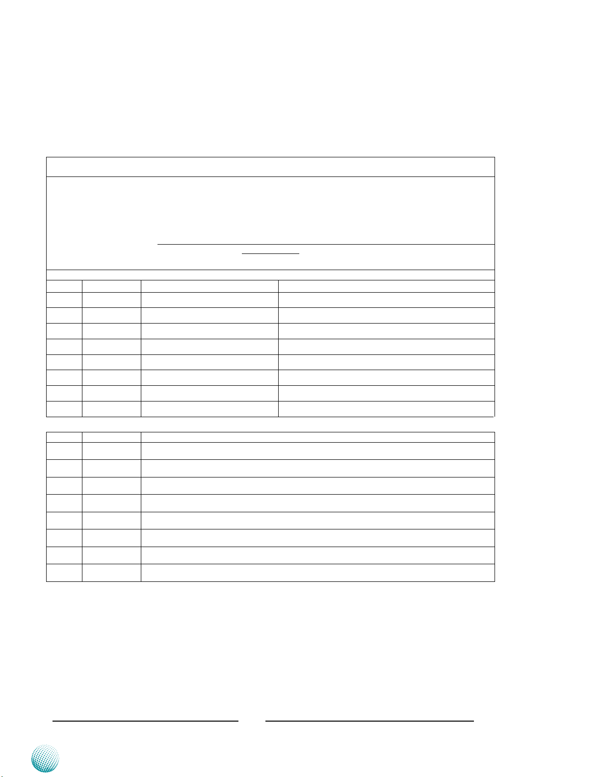
RMA Service Request Form
When requesting RMA service, please fill out the following form. Without
this form enclosed, your RMA cannot be processed.
RMA No:
Reasons to Return: Ŀ Repair(Please include failure details)
Ŀ Testing Purpose
Company: Contact Person:
Phone No. Purchased Date:
Fax No.: Applied Date:
Return Shipping Address:
Shipping by: Ŀ Air Freight Ŀ Sea Ŀ Express ___
Ŀ Others:________________
Item Model Name Serial Number Configuration
Item Problem Code Failure Status
*Problem Code:
01:D.O.A.
02: Second Time
R.M.A.
03: CMOS Data Lost
04: FDC Fail
05: HDC Fail
06: Bad Slot
07: BIOS Problem
08: Keyboard Controller Fail
09: Cache RMA Problem
10: Memory Socket Bad
11: Hang Up Software
12: Out Look Damage
13: SCSI
14: LPT Port
15: PS2
16: LAN
17: COM Port
18: Watchdog Timer
19: DIO
20: Buzzer
21: Shut Down
22: Panel Fail
23: CRT Fail
24: Others (Pls specify)
Request Party
Confirmed By Supplier
Authorized Signature / Date Authorized Signature / Date
Terms and Conditions
Embedded and Industrial Computing
48
 Loading...