

Page 1
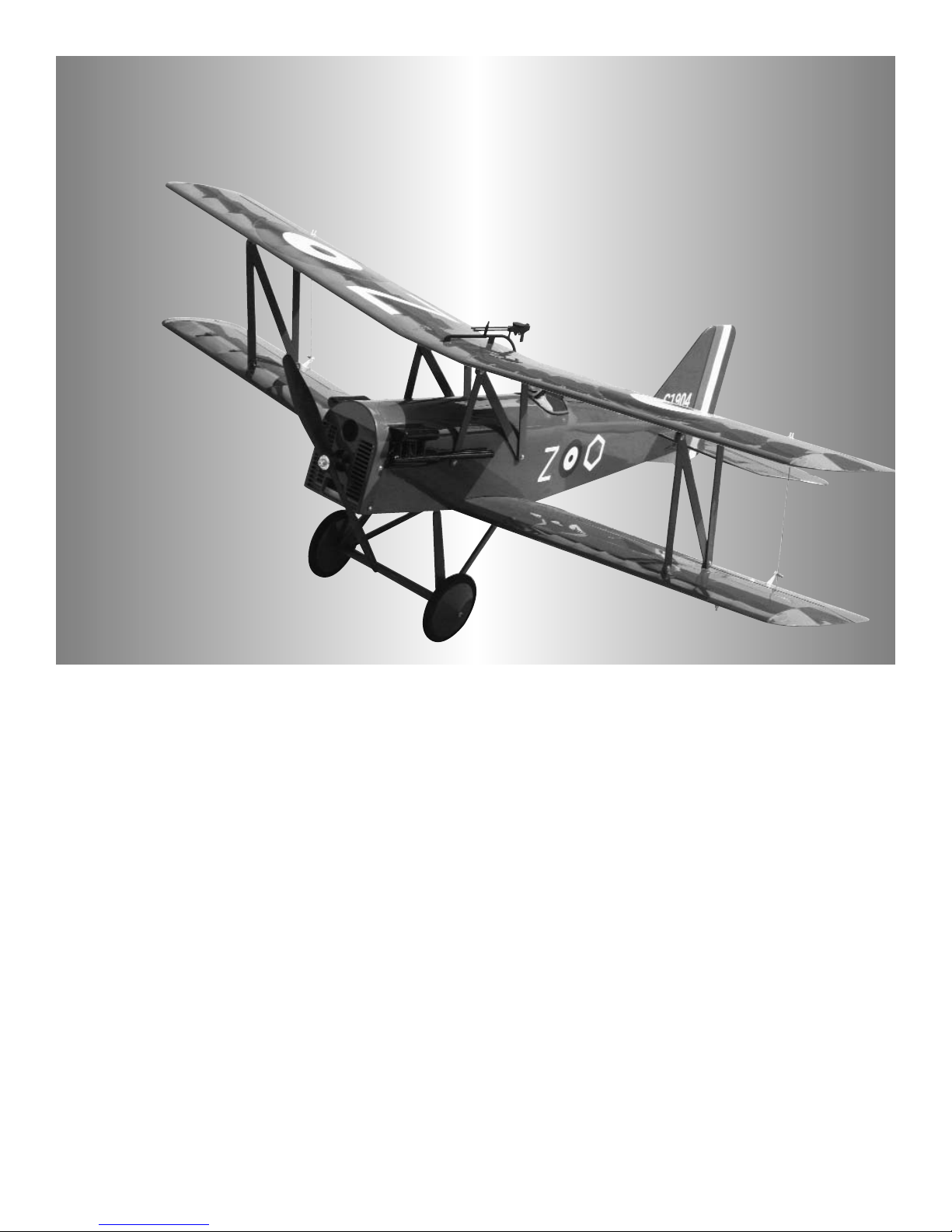
S.E.5a
Lanier R/C, INC. P.O. Box 458 Oakwood, Ga. 30566 PH 770 532 6401
© copyright 2006 Lanier R/C
Important Information:
Please inspect the plane before beginning to assemble to make sure you are happy with it. After
assembly has begun you cannot return the kit. If you find a problem before beginning to assemble the
plane you must contact us, please do not return it to the dealer. Due to temperature changes the plane
may develop some wrinkles in the covering that you will need to remove with an iron. Be sure to seal
the edges down first so that you do not cause the covering to shrink and leave exposed areas of wood.
The model is built light to ensure good flight characteristics. With the power available from the new
breed of engines, it is necessary to use throttle management in order not to overstress the airframe.
You must maintain good tight control linkage with no slop, good servos with plenty of power, and good
servo arms to protect against flutter. Sloppy linkage and over speeding the plane will cause flutter
which is not covered in the warranty. Lanier R/C is proud of the care and attention that goes into the
manufacture of parts for its model kits. The company warrants that for a period of 90 days, it will
replace, at the buyers request, any parts or material shown to the company’s satisfaction to have been
defective in workmanship or material at the time of purchase. No other warranty of any kind, expressed
or implied, is made with respect to the merchandise sold by the company. The buyer acknowledges
and understands that he is purchasing only a component kit from which the buyer will himself construct
a finished flying model airplane. The company is neither the manufacturer of such a flying model airplane, nor a seller of it. The buyer hereby assumes the risk and all liability for personal or property
damage or injury arising out of the buyers use of the components or the finished flying model airplane,
whenever any such damage or injury shall occur. Any action brought forth against the company, based
on the breach of the contract of sale to the buyer, or on any alleged warranty there under, must be
brought within 1year of the date of such sale, or there after be barred. This one year limitation is
imposed by agreement of the parties as permitted by the laws of the state of Georgia.
Page 2

2
USING THIS INSTRUCTION MANUAL
Before you begin assembling your S.E.5a ARF, take some
time to read through this entire instruction book. It is
designed to take you step-by-step through the process and
to give you added information on motor and radio selection
and set-up, balancing your aircraft, and flying your model.
The time you spend will speed the assembly process and
help you avoid problems.
PREPARING FOR ASSEMBLY
You will need a work area of approximately 24 x 48" which has
been covered to protect it from adhesive, as well as cuts and
other damage. Many people cover their work area with a
sheet of dry wall (sheet rock) and/or waxed paper t o prevent CAGlue and Epoxy from ruining the work surface.
CONSTRUCTION TIPS
IMPORTANT: ALWAYS READ A FEW STEPS AHEAD.
This will alert you to coming instructions and will help you
plan accordingly.
Using the Parts Identification section, familiarize yourself
with the various items included in your kit box.
Do not hesitate to ask questions. Your local hobby dealer
and area flyers will most likely be happy to help, as they
want you to have a successful flying experience.
ADHESIVES & GLUING TECHNIQUES
CA adhesives are specially formulated to firmly glue the
plywood, hardwood, and balsa used in your model and to
withstand the vibration and stresses of high performance
flight. However, there are times, such as when you are
installing the stabilizer and fin on the fuselage and want
more set-up time for careful alignment and positioning,
then you should use epoxy. Occasionally, you also will
want to use thin CA, which "wicks" into the surrounding
areas. Aliphatic resin glue or similar water-based glues can
also be used, but they will add to the assembly time
because they dry so much more slowly than CA glue.
Remember, when ever using any CA, you must be careful
to read instructions thoroughly, as you will have only seconds for positioning of parts. Be sure to trial fit parts
together before gluing. Also, never use watery THIN type
CA glue for gluing plywood and hardwood parts. Thin CA's
do not adequately bond these areas.
CAUTION
Some people may experience an allergic reaction when
exposed to fumes from CA glue or epoxy. As with paints,
thinners, and solvents, it is always important to use glues
only where there is adequate ventilation to carry fumes
away. A fan is recommended. Also, special care must be
taken when using CA, as it will bond skin as well as other
surfaces. Before using any CA, carefully read all label precautions. When using CA, protective eye-wear and care in
keeping the glue away from the face is highly recommended. If CA does happen to get into the eye, hold lid open
and flush with water only. Seek immediate medical attention.
COVERING
The S.E.5a ARF is covered in a polyester film chosen for
its beauty, toughness, and ease of application and repair.
It is not uncommon for ARF's to develop a few wrinkles in
transit. If this is true of your model, the situation is easily
corrected. Before you begin putting the pieces together,
run around the edge of the seams first then over the surface of each section with an iron (either specially designed
for airplane use or the more cumbersome household iron).
Apply the heat (set at about 300° F), following along with a
soft cloth and pressing down on the covering as you go
around. This will more firmly set the covering adhesive into
the wood and keep your aircraft covering tight and smooth
in the future. Once you have ironed the seams stay away
from them with the heat or the covering will slide when you
try to shrink the middle. If this happens the wrinkles will not
come out of the covering.
One of the great advantages of polyester film is that it can
be applied over itself without causing gas bubbles. This
allows you to repair your aircraft, as well as to customize it
in a number of ways. If, due to a flight mishap, you get a
hole or similar covering damage, simply trim away the
ragged edges and then apply a patch, following the directions that come with your covering , which is available at
your hobby dealer.
The S.E.5a covering can be closely matched
using
Oracover Red #871
Oracover White #870
Oracover Olive Drab #904
Oracover Blue #873
Oracover Cream #878
Page 3

3
ITEMS NEEDED TO COMPLETE THIS AIRCRAFT
1 4 CHANNEL RADIO WITH 4 MICRO SER-
VOS. (WE USED 4 CHANNEL FUTABA
RADIO WITH S3110 SERVOS AND
FUTABA RECEIVER )
1 6” SERVO “Y” HARNESS
2 12” SERVO EXTENSIONS
1 ELECTRONIC SPEED CONTROL (WE
USED A CASTLE CREATIONS PHOENIX
25 BRUSHLESS SPEED CONTROL)
1 3 CELL LI-PO BATTERY (GREAT PLANES
ELECTRICFLY 1500)
1 ULTRAFLY BRUSHLESS MOTOR A/30/29
WITH 3.89 GEAR RATIO
1 GREAT PLANES ELECTRIFLY PROP
ADAPTER 3MM APC LONG
1 APC PROPELLER 9 X4.7 SLO FLYER
1 CA ACCELERATOR
1 1 OZ. BOTTLE CA MEDIUM GLUE
1 1/2 OZ. BOTTLE CA THIN GLUE
1 5 MINUET EPOXY
1 1/4” FOAM RUBBER
1 SHEET METAL SCREWS FOR
MOTOR(MIGHT BE REQUIRED FOR SOME
MOTOR INSTALLATIONS)
TOOLS AND SUPPLIES FOR ASSEMBLY.
MODELING OR UTILITY KNIFE
WORK SURFACE (24" X48")
SMALL STANDARD & PHILLIPS SCREW-
DRIVERS
MASKING TAPE
NEEDLE NOSE PLIERS
24” RULER
FLEXIBLE STRAIGHT-EDGE
30-60-90° x 6" TRIANGLE
SOFT PENCIL
A FEW STRAIGHT OR "T" PINS
WIRE CUTTER (DYKES)
OPTIONAL HEAT GUN/COVERING IRON
ACID BRUSH
5 FT. LENGTH OF STRING
Caution:
Before starting, carefully go
over all high stress areas
(Wing bolt mounting blocks,
Firewall,etc.) with an epoxy or
wood glue to confirm all
areas are well glued.
Warnings about Lithium
Polymer batteries
NEVER charge Lithium Polymer batteries with a
charger designed for NiCd, NiMH, or any
other type of battery chemistry. Use ONLY
the chargers listed under REQUIRES or
equivalent substitutes.
Do not allow Li-Po cells to overheat at any time. Cells
which reach greater than 140° Fahrenheit
(60C) will usually become damaged and
could catch fire.
Do not charge or discharge Li-Po cells on or near
combustible materials including paper, plastic,
carpets, vinyl, leather, wood, inside an R/C
model or full size automobile.
Do not expose Li-Po cells to water or moisture at any
time.
Do not store batteries near an open flame or heater.
Do not assemble Li-Po cells or pre-assembled packs
together with other Li-Po cells or packs.
Do not allow a Li-Po battery to be left unattended dur-
ing charging or discharging.
Always store Li-Po batteries in a secure location
away from children.
Always remove a Li-Po battery if model is involved in
any kind of
crash. Carefully inspect the
battery and connectors for even the
smallest damage.
CAUTION, cells may be hot!
Do not allow the electrolyte to get into eyes or on
skin. Wash affected areas immediately if
they come into contact with electrolyte.
Page 4
Installing Ailerons
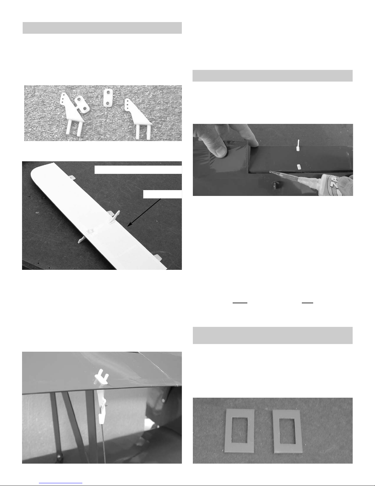
1. Collect the following parts:
(2) Wings
(4) Ailerons ( Left & Right)
(12) Mini CA hinges
2. Locate the pre-cut aileron hinge slots in both
sides of the wing. Using a hobby knife (#11
blade), slide the blade into each slot to make
sure it is cleanly cut.
Repeat this process with the ailerons, making
sure all hinge slots are clean.
3.
Insert the mini CA hinges half way into the
wing and the ailerons. (Use a pin inserted into
the middle of the hinge to help keep the hinge
in the middle.)
Make sure that the aileron is tight against the
wing and even with the wing tip.
Using thin CA glue, place one drop on all
hinges top and bottom.
Repeat for the other three ailerons.
Aileron Control Horns
1. Gather the following items:
(6) Small Control Horns
(2) Wing
(2) EZ Connectors With Hardware
(2) Swivel Keeper
2. Cut the back plate off the side of the control
horn.
3. Locate the pre-drilled control hole holes in the
aileron. The control horn on the bottom side
faces toward the leading edge of the aileron.
The other control horn goes on the top side of
the aileron and faces the trailing edge.
Place glue on the control horn pins and insert
them in the holes.
Place the plate on the pins on the opposite
side and glue in place.
bottom side of bottom wing aileron
leading edge
4. Install the two control horns on the top wing
ailerons on the bottom side facing the rear.
Installing Aileron Servos
1. Gather the following items:
(2)12" Extension wires
(1) Bottom Wing
(2) Servos
(1) Electrical tape
(2) Servo spacers
Page 5
5
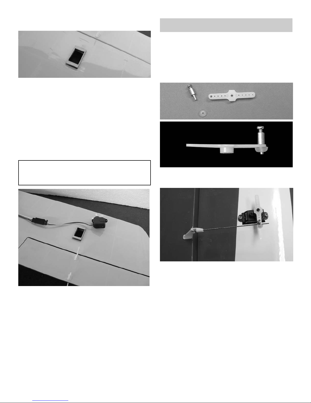
2. Mount the EZ connector hardware on the
aileron servo arm.
3. Find the small aileron pushrod wire.
Make a 90º bend (or a "z" bend, if preferred)
1/4” from the end of the wire
Insert the wire into the control horn.
Secure the wire with a nylon swivel keeper.
4.
Insert the other end of the push rod through
the EZ connector.
Mount your servo arm on top of your servo.
5. Repeat for the other servo in the other wing.
2. Locate the two aileron servo spacers.
IMPORTANT! To ensure that any connections located
inside the wing will not come loose, either when the
wires are pulled, or during flying, always tape them
securely together with electrical tape.
3. Lay the spacer over the cutout for the aileron
servo and mark around the outside edge.
Carefully remove the covering inside your
marks and glue the spacer plate in place.
4. Use the string to pull the aileron wires through
the wing and exit the hole in the center section.
5. Mount the servo using the hardware supplied
with the servo.
6. Repeat for the other wing.
Aileron Pushrods
1. Gather the following items:
(2)12" Extension wires
(1) Bottom Wing
(2) Servos
(1) Electrical tape
(2) Servo spacers
Page 6
6
Main Landing Gear
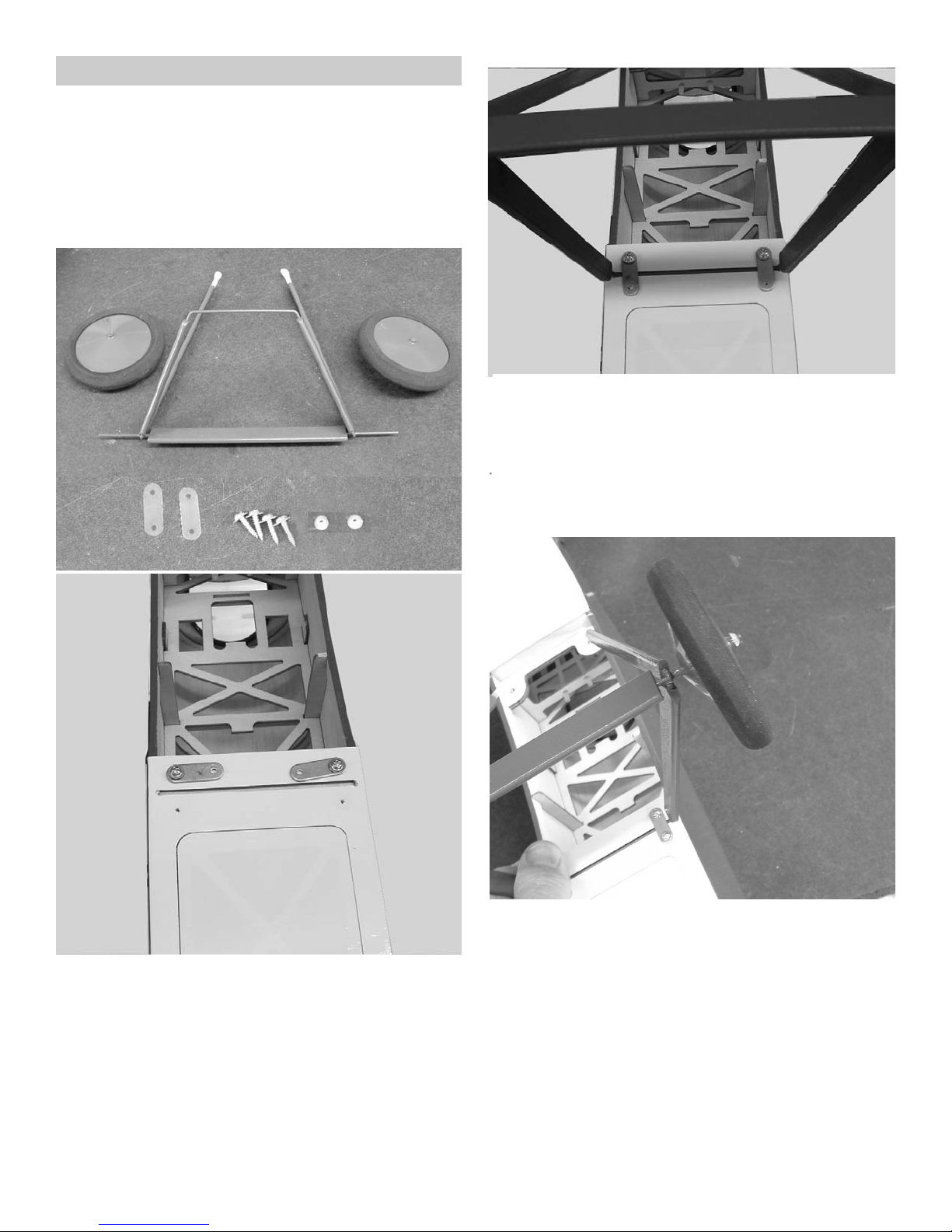
3. Fit the gear into the slot on the bottom of the
fuselage.
Swing the two straps into place over the wire
and install the other two screws. The two rear
supports go under the wing mounting bolts
when the bottom wing is installed.
1. COLLECT THE FOLLOWING PARTS:
(1) Fuselage
(1) Main Landing gear
(4) #2 x 3/8” screws
(2) Main Wheels
(2) nylon wheel retainers
(2) landing gear straps
4. Fit the main wheel on the axle and hold in
place with the press on nylon keeper.
Repeat for the other wheel.
2. Use two of the screws and mount the landing
gear straps to the fuse in the rear holes.
Page 7
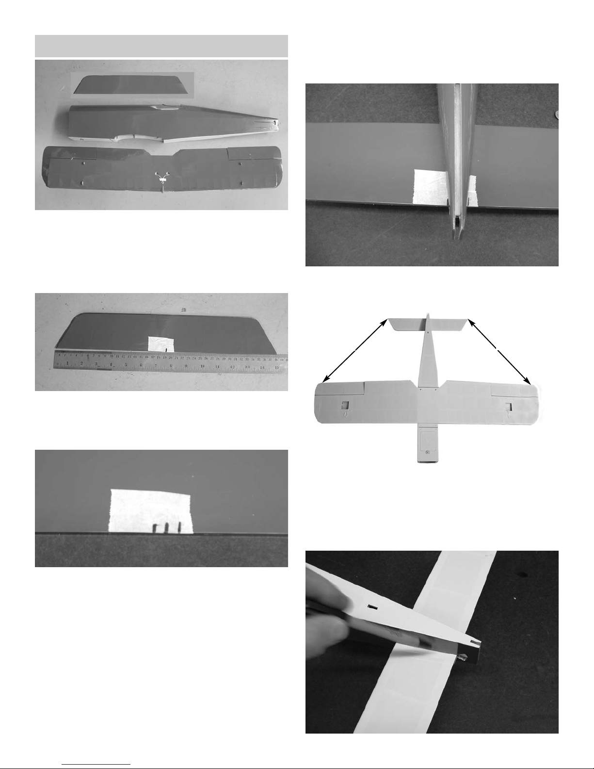
Installing Stabilizer
1. COLLECT THE FOLLOWING PARTS:
(1) Fuselage
(1) Stabilizer
(1) Bottom wing
(2) #4 x 3/4” screws
4. Mount the bottom wing to the fuselage using
the two #4 x 3/4” bolts.
5. Slide the stab into the fuselage and align the
center marks on both sides of the fuselage.
2. Put a piece of masking tape along the trailing
edge of the stab and measure and make a
mark in the center of the stab.
3. Make another mark on each side of the center
line 1/4” over. These two marks will line the
stab up in the center of the fuselage at the
rear.
A
A
6. Measure out the wing on each side an equal
distance and make a mark. Measure from the
tip of the stab to the mark on the wing and
adjust stab until both sides are the same( A
equals A)
Page 8
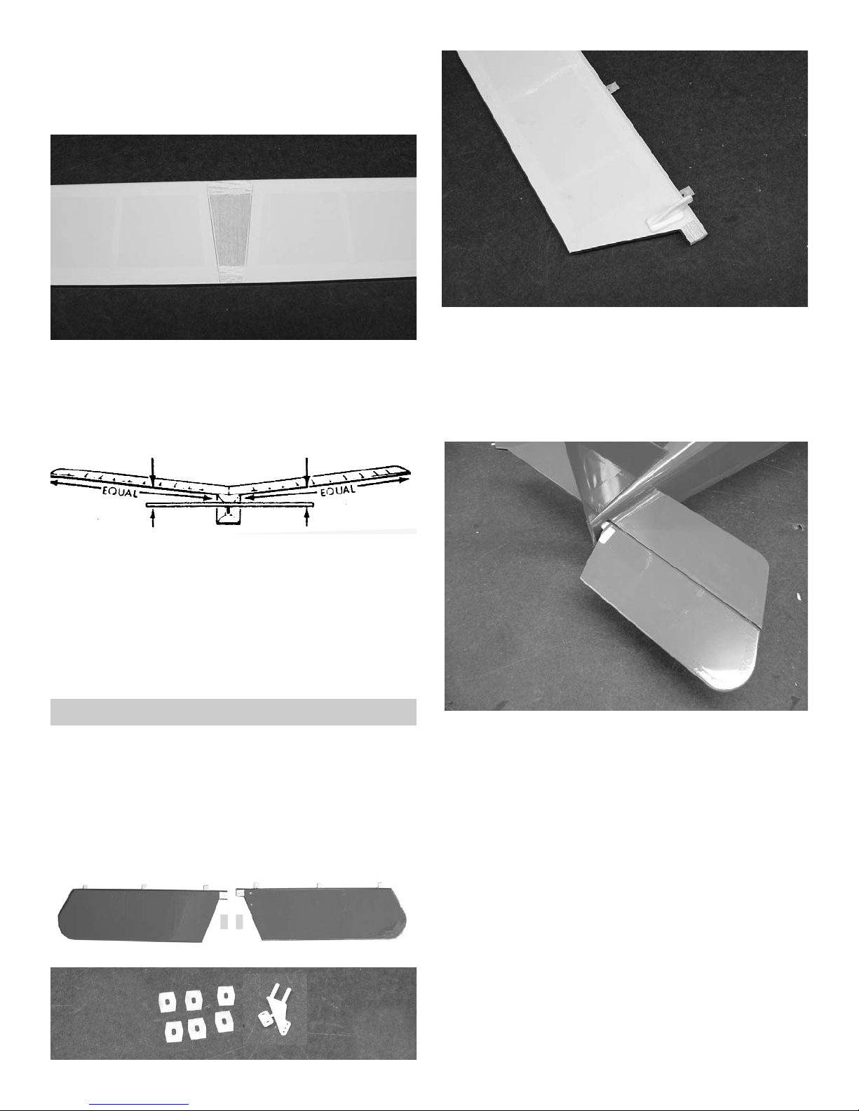
8
Look down the length of the fuselage and
check that the stabilizer is parallel to the wing.
If it is not then shim the low side till they are
parallel.
When satisfied then glue the stabilizer in place
using 5 minuet epoxy. Make sure the stabilizer remains both perpendicular and parallel to
the wing and fuselage while the epoxy dries.
7. When stab is properly aligned, make a mark
along side the fuselage on the stab top and
bottom, left side and right side.
8. Carefully cut the covering 1/8” inside the line
you marked and remove. Don’t cut into the
wood as this will weaken the structure.
Remove covering both top and bottom.
Elevator Installation
1. Collect the following parts:
(1) Fuselage With Stabilizer
(2) Elevators
(6) Mini CA Hinges
(2) Plastic elevator joiners 3/8” x 1”
(1) nylon control horn
2. Locate the pre-drilled control hole holes in the
right side elevator. .
Place glue on the control horn pins and insert
them in the holes.
Install the plate on the pins on the top side and
glue.
3. Insert 3 hinges half way into each elevator
Slide the elevator hinges into the stabilizer.
4. Make sure the elevator is pushed up tight
against the stabilizer and the end of the elevator is even with the end of the stabilizer.
Page 9
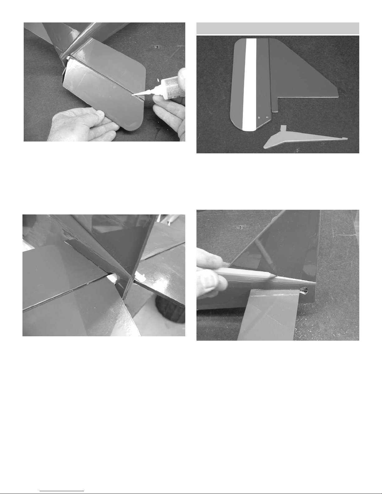
9
5. Deflect the elevator to it full travel (about 1”)
and glue the hinges in place using thin CA
Turn the plane over and repeat for the bottom
side.
6. Repeat steps 3,4, and 5 for the left elevator.
7. Join the two elevator halves in the center
using the 3/8” x 1” strips of plastic. Glue one
on the top of the elevators where they meet in
the center and one on the bottom side.
Fin & Rudder Installation
1. Collect the following parts:
(1) Fuselage With Stabilizer
(2) Fin & Rudder
(2) Mini CA Hinges
(1) Nylon Control Horn
(1) Tail skid
2. Fit the fin into the notch on the top of the fuse-
lage and mark around the top edge of the
fuselage.
Page 10
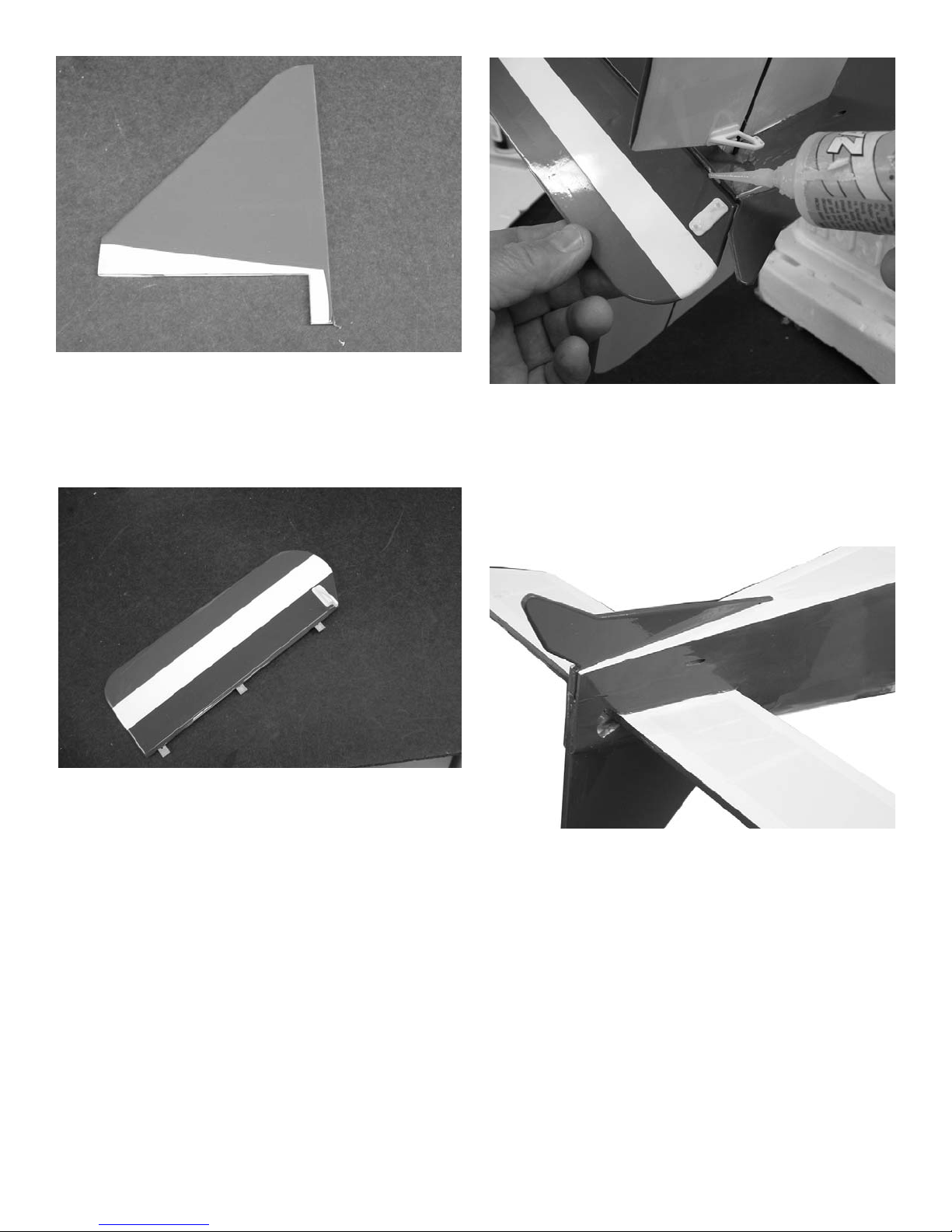
10
3. Remove the covering by cutting 1/8” inside
the line you marked making sure not to cut
into the wood.
Glue the fin into the fuselage using epoxy.
2
4. Place a drop of glue on the control horn and
insert the rudder control horn in the left side
rudder holes.
Insert the back plate onto the control horn pins
sticking out the other side of the rudder.
Place a drop of glue on the pins to hold the
back plate in place.
5. Fit the hinges into placed on the fin and make
sure the rudder is tight against the fin. Deflect
the rudder to one side about 1-1/2” and glue
hinges with thin CA.
Deflect the rudder in the other direction and
glue the hinges on the opposite side.
6. Glue the tail skid into the notches provided on
the bottom of the fuselage.
Page 11
11
3. Repeat step 2 for the elevator pushrod and
control horn.
Pushrod Installation
1. Collect the following parts:
(2) Nylon swivel keepers
(2) 20” Long Pushrod Wire
2. Insert the pushrod into the tube in the fuse-
lage.
Make a 1/4” bend at the end of the pushrod
and place it in the control horn.
Place a swivel keeper on the end of the
pushrod.
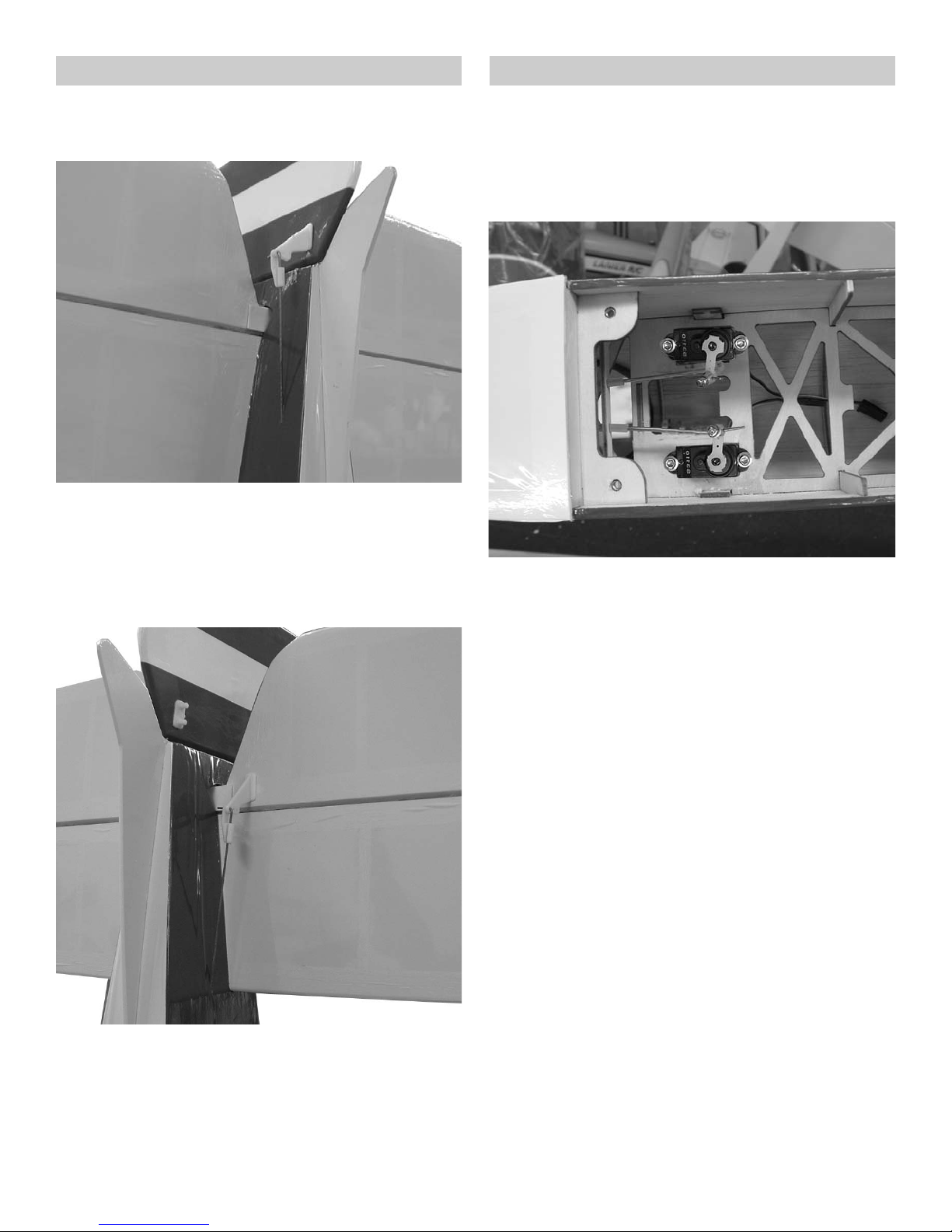
2. Mount the elevator and rudder servo as
shown above.
Attach the EZ connectors to the servo arms
the same way you did the aileron servos.
Insert the pushrod wires through the EZ con-
nectors and mount the two servo arms to the
top of the servos.
Cut off the excess pushrod wire.
3.
Plug the elevator and rudder servos into your
receiver.
Attach the “Y” harness to the receiver in the
aileron channel.
Plug in the speed control.
Cut foam and wrap around the receiver.
4.
Put the receiver wrapped in foam in front of
the servos.
Radio Installation
1. Collect the following parts:
(1) Fuselage
(2) Micro Servos with Hardware (Not Included)
(1) Micro Receiver (Not Included)
(1) Servo “Y” Harness (Not Included)
(2) Mini- Pushrod Connectors
Page 12
12
Top Wing Installation
1. Collect the following parts:
(2) Cabane struts
(2) N- struts
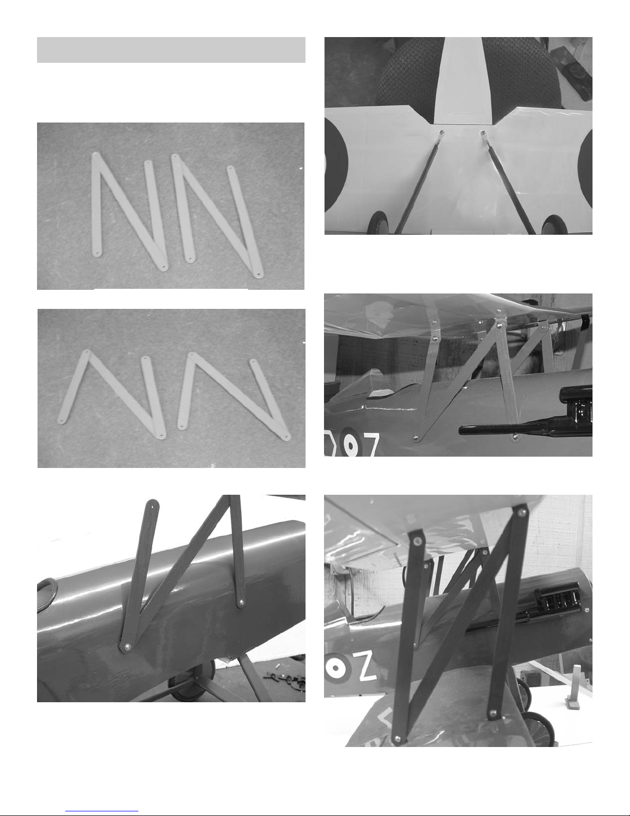
(16) #2 x 3/8” screws
2. Attach the cabane struts to the fuselage side
as shown above. Use the pre-drilled holes in
the fuselage side to locate them.
N-Struts
Cabane Struts
3. Bolt the bottom wing in place with the landing
gear struts under the wing bolts.
4. Set the top wing in place on the cabane struts
and install the four screws.
5. Install the N-struts and secure with four
screws.
Page 13
13
Installing Motor & ESC
1. Collect the following parts:
(1) Fuselage
(1) Motor (Not Included)
(1) Electronic Speed Control (Not Included)
(1) Screw for motor installation (Not Included)
Note:
Read the instructions that come with your
motor and speed control for proper wiring.
Your Motor and Speed Control might be dif-
ferent than shown.
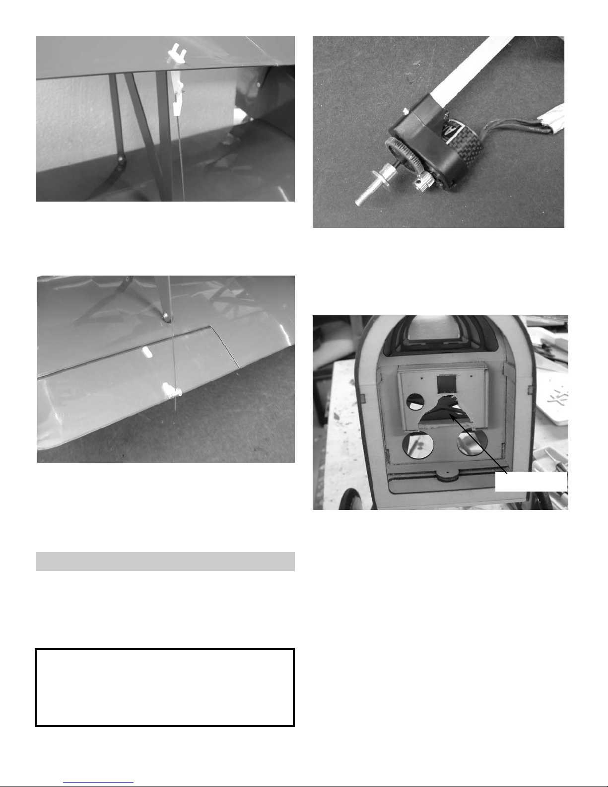
6. Locate the 1/32” x 7” aileron pushrod and
make a 90 degree bend 1/4” long in one end.
Fit it into the outer hole on the top aileron control horn and retain with the swivel keeper.
7. Fit the bottom end of the pushrod into the e-z
connector on the bottom wing aileron.
Center both ailerons and tighten the set
screw.
2. We used the Ultra fly A30-29 brushless motor
which comes with the gear box and prop
adapter. It mounts on a 3/8” square stick
which is supplied with the plane. The firewall
is set up to accept either the 3/8” square
mount or an outrunner radial mount.
3. If using the 3/8” stick mount you will need to
remove some wood below it to allow the motor
wires to clear the firewall.
remove
Page 14
Caution:
Do not install the propeller at this time.
Electric motors can start turning at any time
during radio installation. This can cause
damage to the plane or bodily harm.
14
Note:
We flew the S.E.5a ARF with a Ultrafly brush-
less motor A/30/29 with 3.89 gear ratio
with a 9 x 4.7 Slo-Flyer APC prop
We also used a Castle Creations Phoenix 25
brushless speed control
This motor system worked well
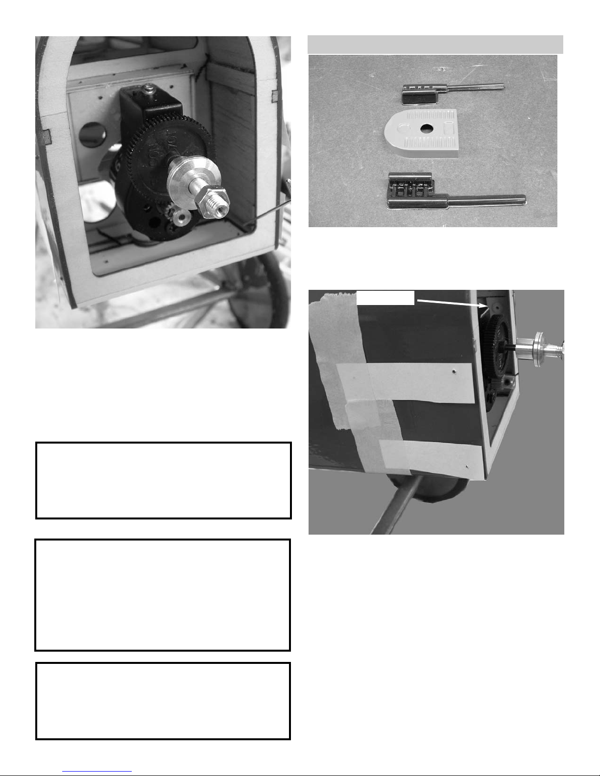
4. Glue the motor stick into the square hole in
the firewall and second bulkhead.
Insert the speed control into the nose through
the wing cutout and pull the wires through the
firewall. Plug the wires into the motor and
slide the motor on the stick and retain with a
screw.
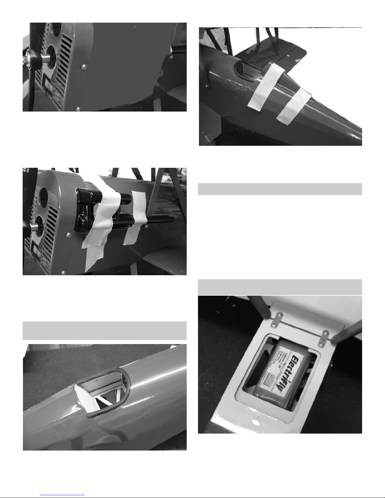
Mounting Cowl
1. Collect the following parts:
(1) Fuselage
(1) Cowl and dummy engine with exhaust
(4) #2 x 3/8 screws
2. Locate the four plastic nuts on the inside of
the fuselage on both side. Take a straight pin
and bend a 90 degree angle on one end and
use it to punch the holes through from the
inside of the fuselage through the plastic nut.
Cut four strips of paper about 1/2” wide and 3’
long and tape to the side of the fuselage. Mark
the location of the holes in the paper.
plastic nut
Caution:
Too much speed will cause flutter on the
control surfaces which can cause structural
failure in the airframe.
WE DO NOT WARRANTY FOR FLUTTER.
Page 15
15
Study the kit box label for decal location.
1.
Using glass cleaner and a soft cloth, clean the
model surface thoroughly before applying
decal's.
Cut the decal sheets apart in sections, as
needed.
Peel the backing off the decal and apply the
decal to the location desired.
Decal Locations
3. Slip the cowl over the nose of the plane with
the paper strips on the outside of the cowl.
Transfer the holes to the cowl.
Screw the cowl in place with four #2 x 3/8”
screws.
4. Using a canopy glue, glue the dummy engines
in place just behind cowl and just above the
mounting screws for the cowl and cabane
struts. The exhaust pipe does not get glued
down past the cabane strut.
Cockpit
1. Install the cockpit combing around the cockpit
and glue in place.
2. Glue the headrest to the top of the turtledeck
and use masking tape to hold in place till the
glue dries.
Battery Location
1. The battery will fit into the compartment on the
bottom of the nose of the plane
2.
We used the Electrifly 1500 mah 3 cell Li-Poly
battery.
Page 16
16
Control Set Up
Turn on your transmitter and plug in the receiver
battery. Center all the control surfaces (rudder,
elevator & aileron). If required by your speed
control this is the time to program it for your
use.
Control Travel
Aileron up / down 1/2”
Elevator up / down 3/4”
Rudder right / left 1”
You will want to adjust these throws to suit
your flying abilities. The throws given are
starting throws.
Balancing
Balance the S.E.5a at 1” back from the
leading edge of the bottom wing
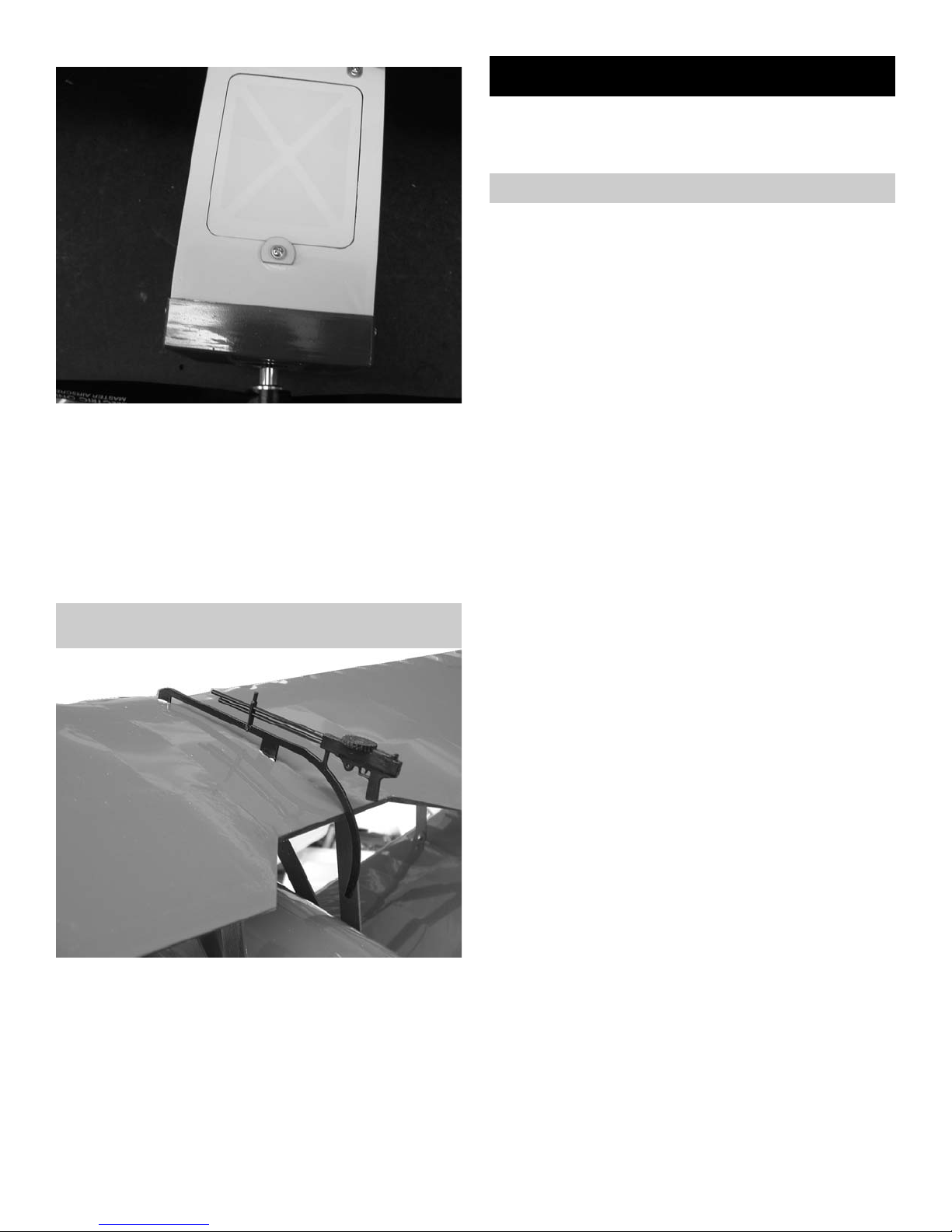
3. The hatch is held in place by the washer and
screw in front. The washer can be rotated to
remove the hatch without removing the screw.
The covering can be removed in the open
areas of the hatch to allow for cooling if necessary.
1. Glue the machine gun in place on the top wing
in the two notches provided.
Machine Gun
 Loading...