

Page 1
Ripper
Ripper
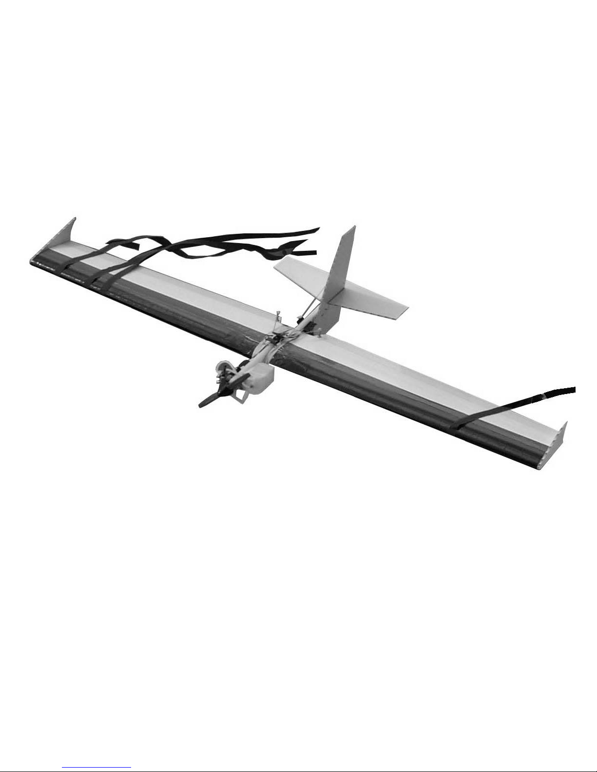
Combat plane for SSC and Open A .15 engines
Lanier R/C Inc.
P.O. Box 458
Oakwood, GA. 30566
Phone 770 532 6401
Fax 770 532 2163
©copyright 2003 Lanier R/C
Page 2

Ripper
Assembly instructions
2
Introduction
Thank you for purchasing the Lanier R/C Ripper Combat Plane. We
believe we have one of the best combat designs for SSC available. It is
very fast to build, will come in at or below the minimum weight, and be
very sturdy in combat. The flight characteristic of the plane allow you
to be very aggressive because you can concentrate on your opponent
and not on keeping the plane in the air. The roll rate is very quick,
allowing you to quickly change from one knife edge to the other and be
on your opponent very quickly. So get on with construction and go get
some streamers.
Important information:
Please inspect the plane before beginning to assemble to make sure you are
happy with it. After assembly has begun you cannot return the kit. If you find
a problem before beginning to assemble the plane you must contact us,
please do not return to the dealer.Lanier R/C is proud of the care and attention that goes into the manufacture of parts for its model kits. The company
warrants that for a period of 30 days, it will replace, at the buyers request,
any parts or material shown to the company’s satisfaction to have been
defective in workmanship or material at the time of purchase.
No other warranty of any kind, expressed or implied, is made with respect to
the merchandise sold by the company. The buyer acknowledges and understands that he is purchasing only a component kit from which the buyer will
himself construct a finished flying model airplane. The company is neither
the manufacturer of such a flying model airplane, nor a seller of it. The
buyer hereby assumes the risk and all liability for personal or property damage or injury arising out of the buyers use of the components or the finished
flying model airplane, whenever any such damage or injury shall occur.
Any action brought forth against the company, based on the breach of the
contract of sale to the buyer, or on any alleged warranty there under, must
be brought within 1year of the date of such sale, or there after be barred.
This one year limitation is imposed by agreement of the parties as permitted by
the laws of the state of Georgia.
To stay under the weight limit of 2.5 lbs. on open A you may need to omit the
leading edge reinforcements. Depending on servos and battery pack used it
may be over 2.5 lbs. For SSC there is no problem since you must be over 2.5
and the plane will come in under that if built with light equipment.
Page 3
Ripper
Assembly instructions
3
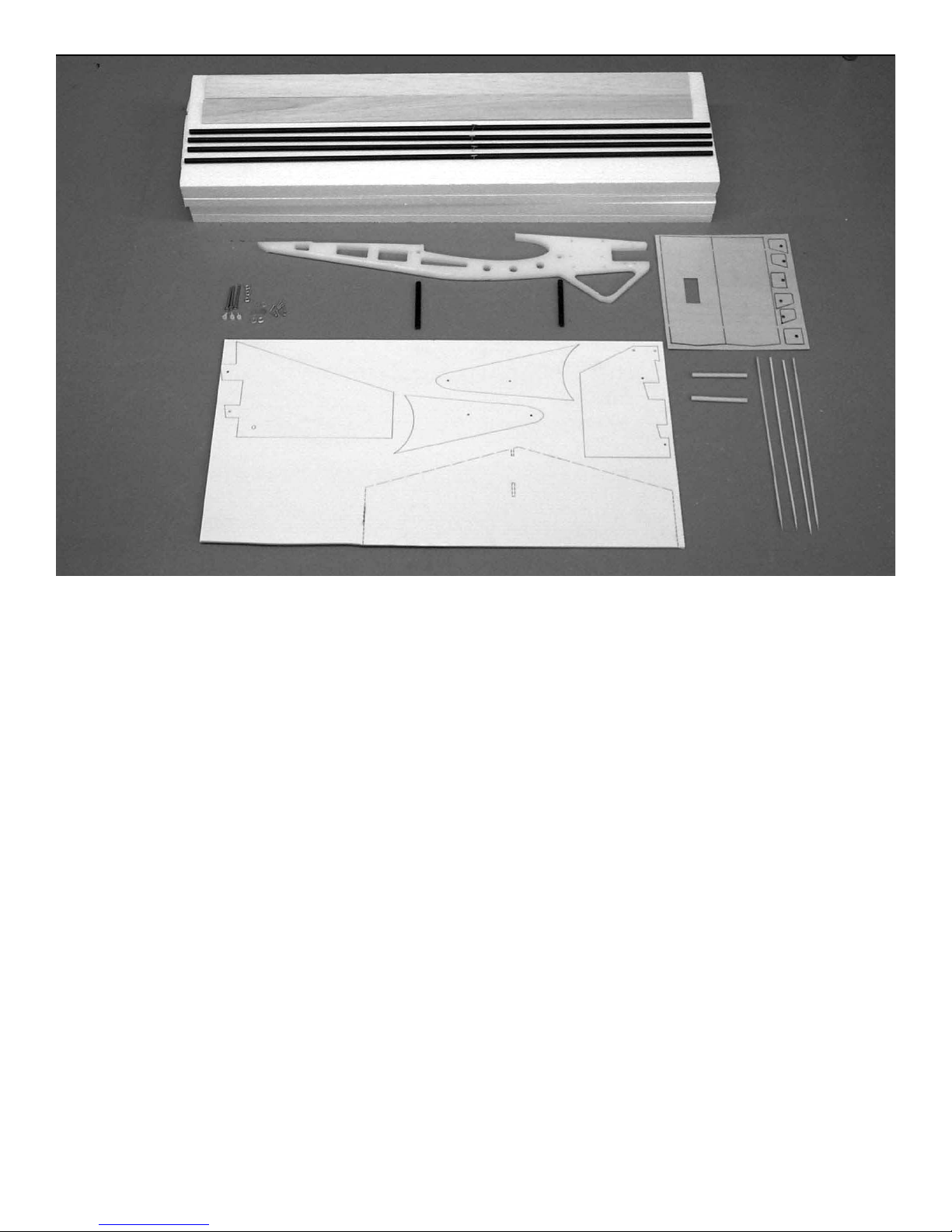
Parts list
1. Wing panels 2
2. Epoxy glass spars 4
3. Balsa Ailerons 2
4. HDPE fuselage 1
5. epoxy glass wing dowels 2
6. Coroplast component sheet 1
7. Hardwood spar joiners 2
8. 1/32” Plywood doublers 1
9. bamboo skewers 4
10. 2-56 threaded pushrods 4
11. 2-56 Golden clevises 4
12. 2-56 jam nuts 4
13. Golden clevis retainer clips 4
14. nylon snap-r-keepers 4
15. 6-32X1-1/2” bolts 3
16 6-32 nuts 3
17. #6 Flat washers 6
18. Nylon pushrod fittings 3
19. #2x1/2” sheet metal screws 6
20. #2x3/4” sheet metal screws 2
21. #4 flat washers 8
22. Laser cut 1/16” plywood
stab reinforcement 1
23.Vacuum formed leading edges 2
24. 1/8” lite ply laser cut trail
ing edge reinforcement.
25. 1/32”x12” plYwood trailing
edge
Page 4
Ripper
Assembly instructions
4
Wing
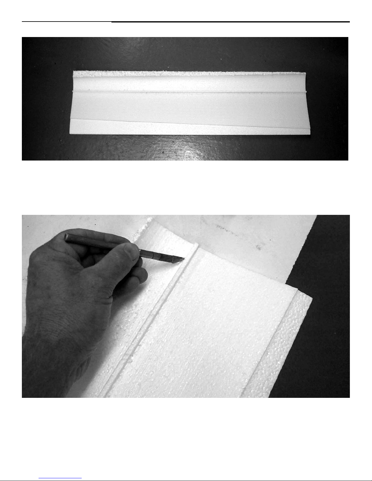
Begin construction with the wing. Remove the wing panels from their cores
and lay aside. All work on the wing panels should be done with the wings laying in the cores so as not to warp them. Using a knife or saw blade, split the
cores down the leading edge so you have a top and bottom half.
Using a knife, remove the foam left from cutting the spar slot in the wing.
This is so you can flip the wing over in the cores after the spars are
installed.
Page 5
Ripper
Assembly instructions
5
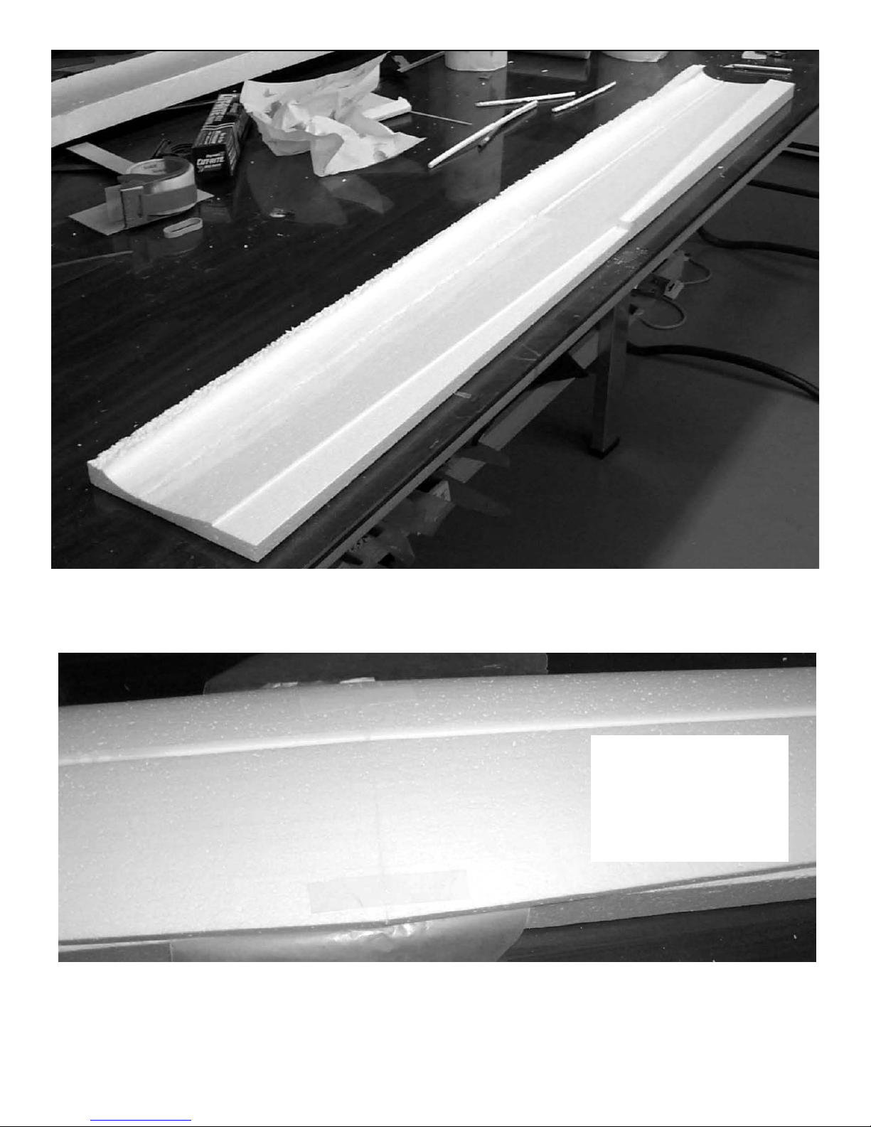
Lay a piece of wax paper over the center of the root so the glue does not
stick the panel to the core when gluing together. Mix some 5-minute epoxy and
spread on the root of both wing panels. Place the panels in the cores and use
masking tape to hold the panels together till the epoxy sets.
Make sure the left
and right panel are
perfectly aligned
with each other
and laying flat in
the cores.
The wings are fully symmetrical so there is no left and right until you glue
on the center doublers. Lay the cores on a flat surface with the roots
butted together, if your table is not straight your wings will not be straight.
You may have to shim one side to make sure the two halves are perfectly even
with each other.
Page 6
Ripper
Assembly instructions
6
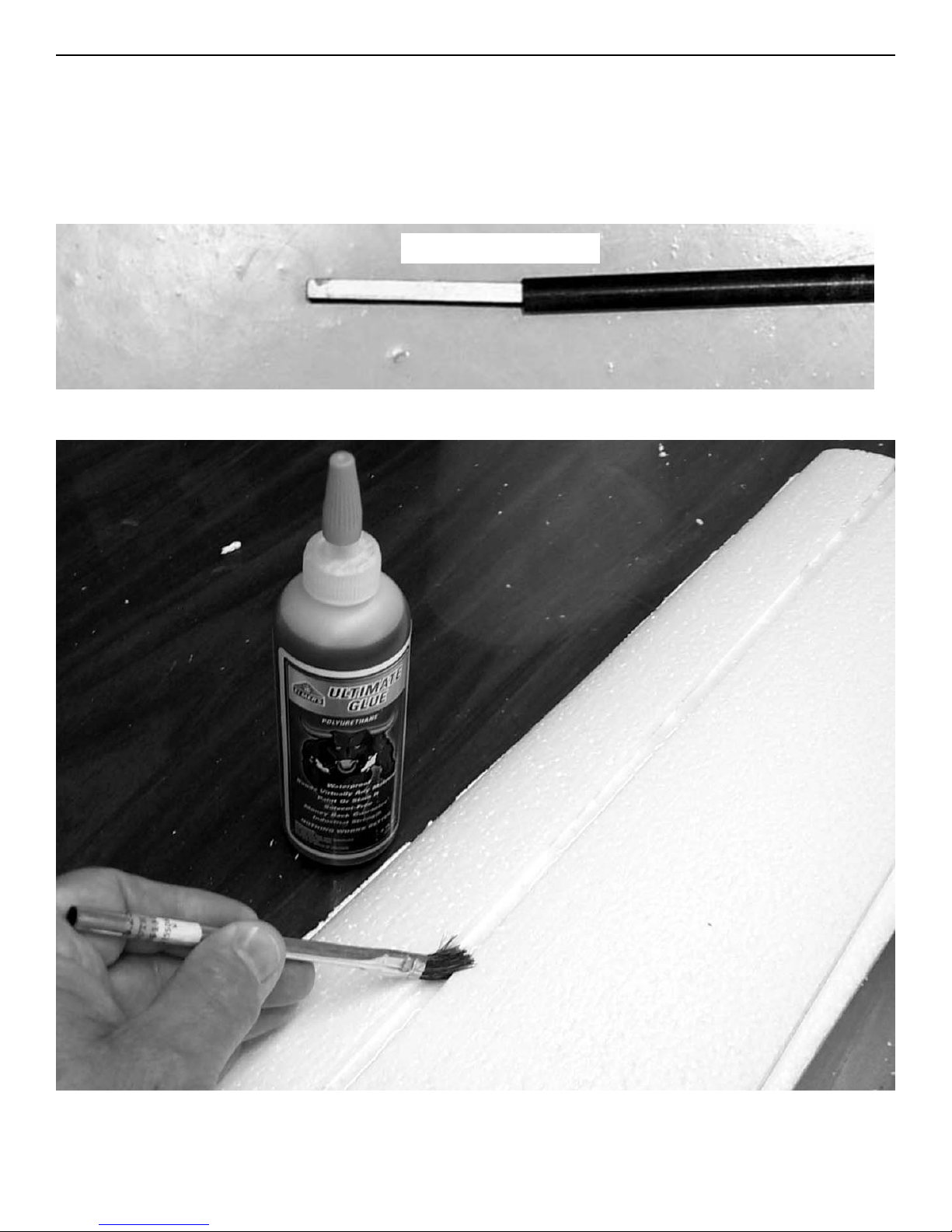
Locate the four epoxy glass spars, and the two laser cut joiners.
Trial fit the spars in the grooves. The spars are at a slight angle,swept forward, so install the joiner with the angle toward the front of the wing.When
happy with the fit, glue a joiner in the end of one of the spars. We recommend
using pro-bond urethane glue which can be purchased at most any hardware
store or building supply such as Home Depot or Lowes. Another name is
Gorilla glue which is the same thing.
using the urethane glue, run a bead down the entire length of the spar slots
and use a brush to make sure it coat the sides and bottom.
note angle
Page 7
Ripper
Assembly instructions
7
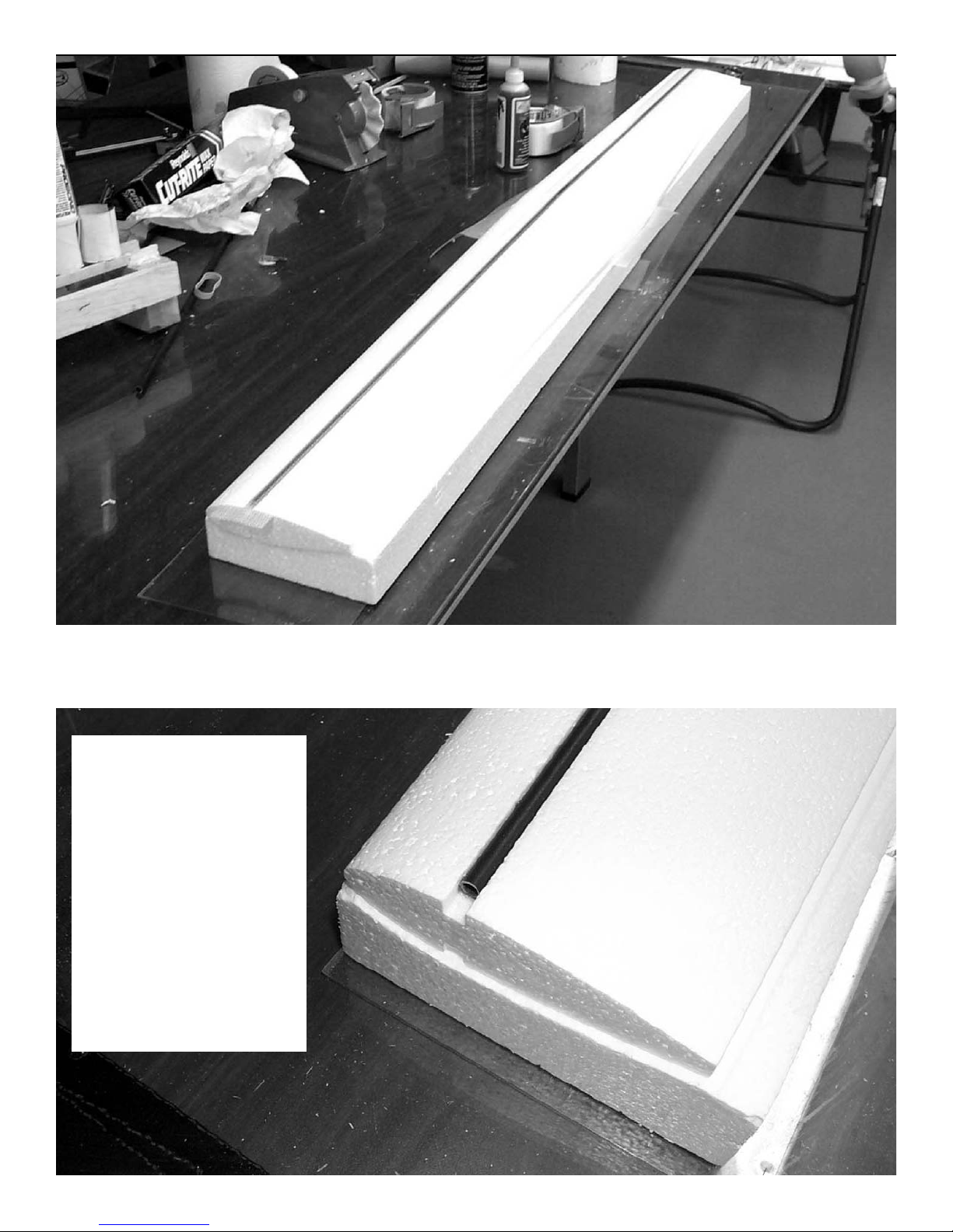
Coat the other end of the joiner and insert it into the other spar. Lay the
spars in the slots and press down firmly. Remember this must be done with the
panels in the cores so as not to warp them.
The spars do not
extend all the way to
the tip. We have
found that in a cartwheel or hard hit on
the end of the wing
the spar can be broken loose from the
panel. By leabint it
about 1/2” short you
have a cushion at the
tip.
Page 8
Ripper
Assembly instructions
8
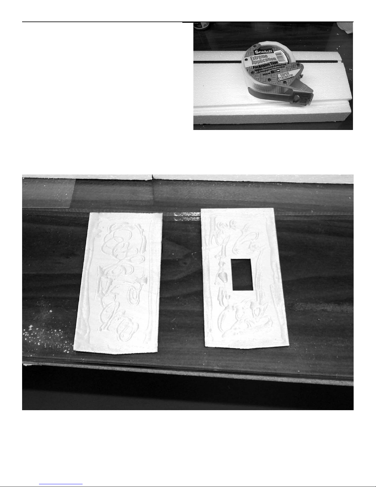
The pro-bond glue will expand when
drying so you must go ahead and
apply the center plywood doublers
and bi-directions tape now or temporarily cover with masking tape till
the glue dries The tape can be purchased at any office supply. It is a 3m
product called extreme application.
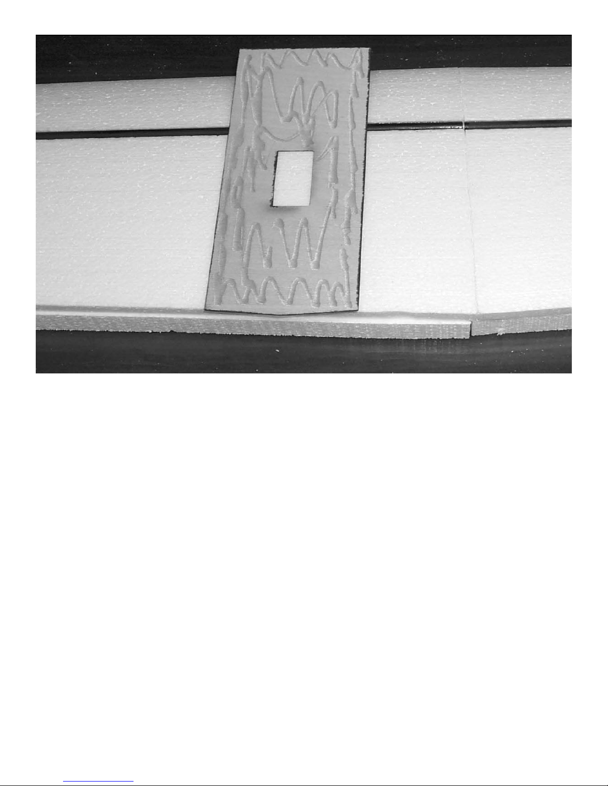
Next locate the top and bottom center section doublers. the top doubler has
the servo cut out and is made of 1/32” plywood. The bottom doubler is 1/32”
plywood.
Coat both pieces with urethane or epoxy glue.Make sure to get a good coat
over the spars so they will be firmly glued to the doublers.
Page 9
Ripper
Assembly instructions
9
Place the doubler in place centered over the seam and aligned with the
trailing edge. Flip wing over and install the bottom doubler. Pull masking
tape around the trailing edge to hold in place. Next pull the leading edge
down and tape in place until the glue dries.
Page 10
Ripper
Assembly instructions
10
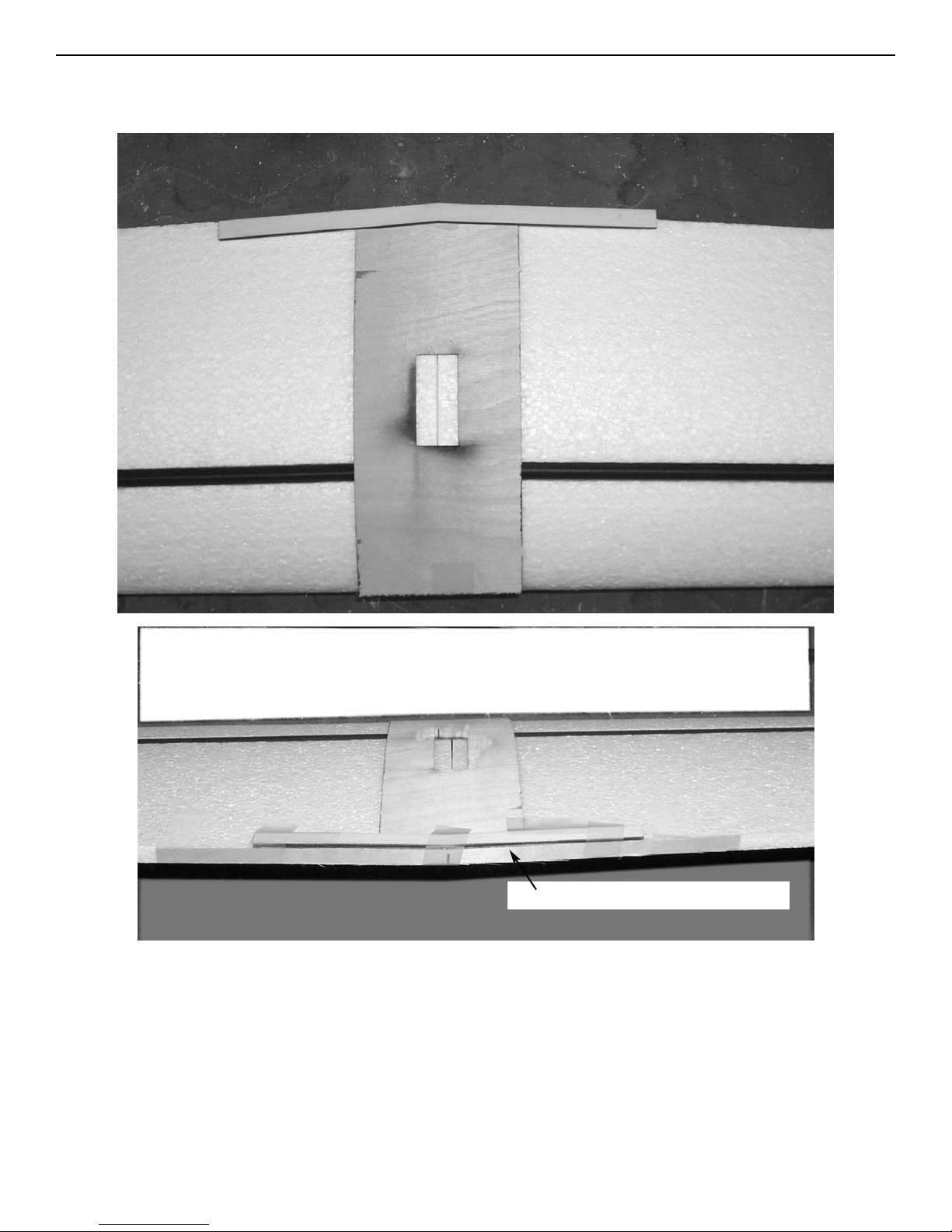
Locate the 1/8” lite ply trailing edge doubler and epoxy in place flush with
the trailing edge of the wing. The angle is cut to match the angle of the trailing edge. This will prevent the rubber bands from crushing the trailing edge
Next locate the 1/32” x 3/8” x 12” plywood strip. Make a mark in the center
and and ailgn on the center line of the wing. Mark a mark at both ends and
carefully sand 1/32” off the foam so the plywood will be flulsh with the
trailing edge. Epoxy to the trailing edge of the wing. This piece will stop the
wing from splitting from the trailing edge up to the wing spars when you hit
the ground hard. All the wood should be glued directly to the foam with the
tape going on top, not under the wood.
1/32” plywood doubler
Page 11
Ripper
Assembly instructions
11
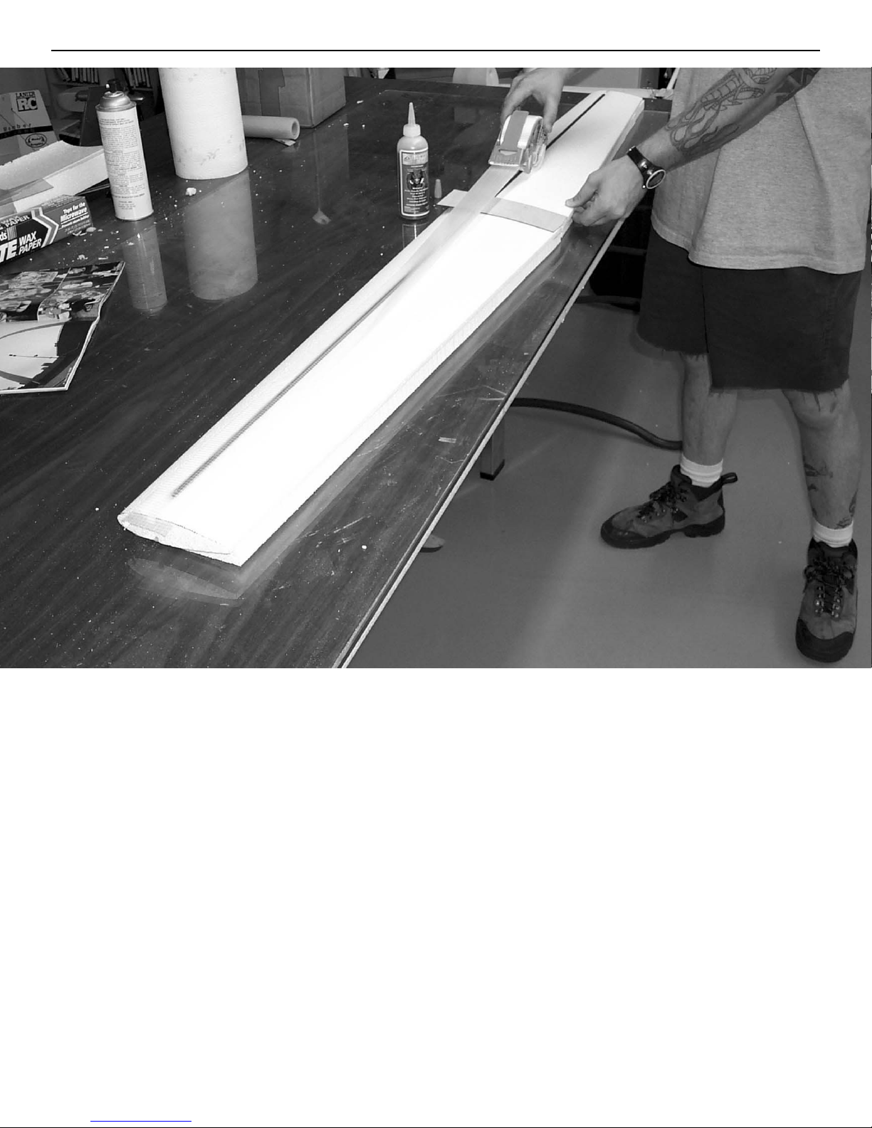
Next pull a single piece of the bi-directional tape from one wing tip to the
other across the center section, center on the spar.
Page 12
Ripper
Assembly instructions
12
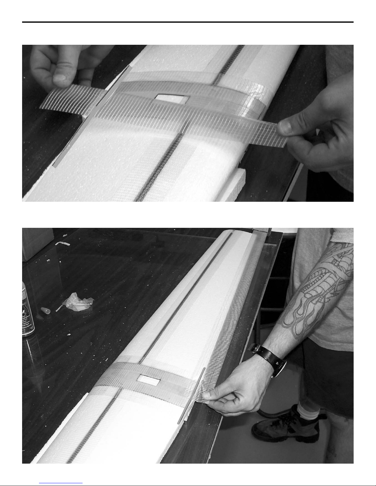
Now tape the center section from front to rear centering the tape on the
edge of the plywood. Do the tapeing both top and bottom.
Page 13
Ripper
Assembly instructions
13
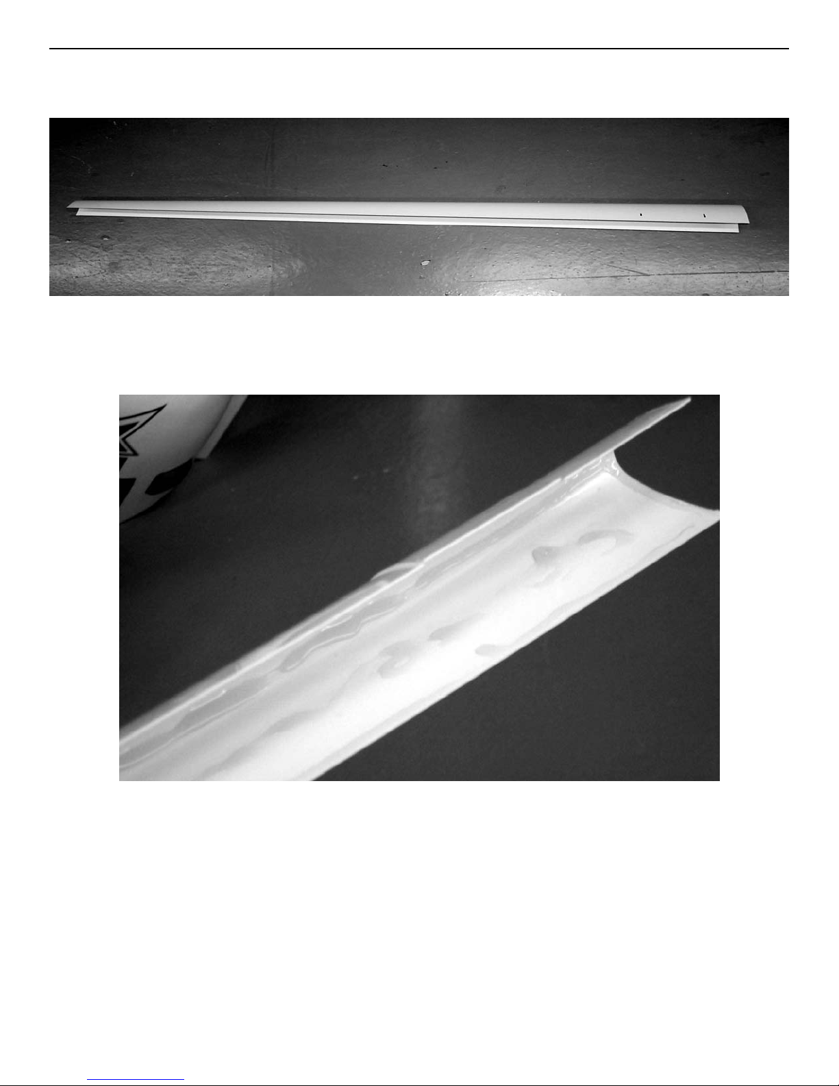
Next pull a piece of the bi-directional tape down the trailing edge, over lap
the top 1 inch then carefully wrap around the trailing edge being careful
not to warp the trailing edge.
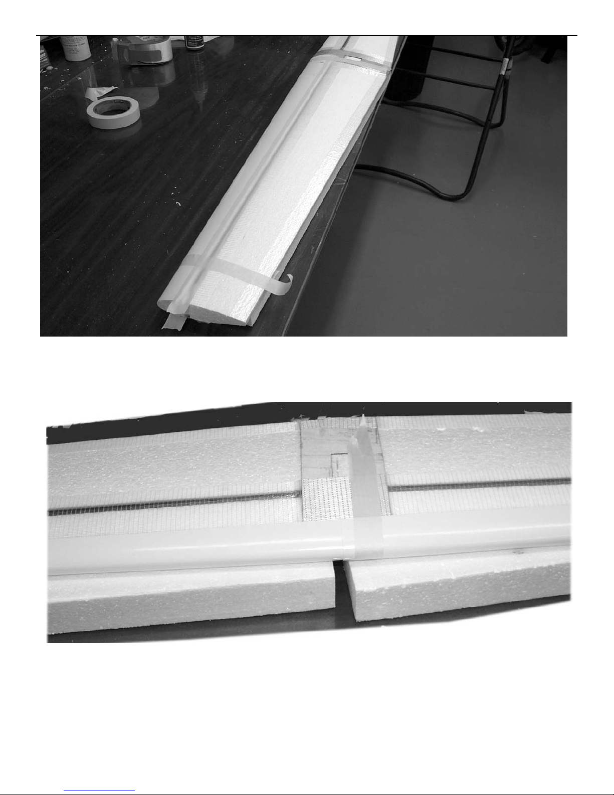
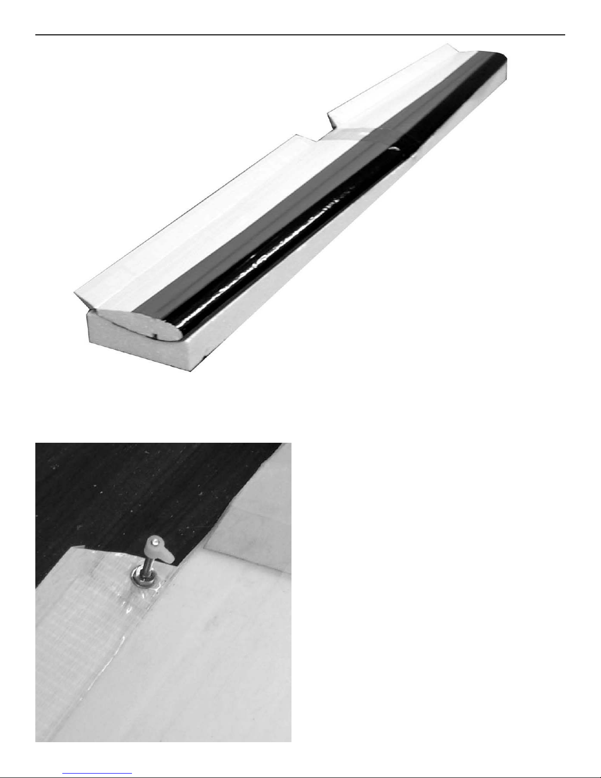
Locate the two pre-formed leading edge caps.
Apply urethane glue to the inside of the leading edge cover. Don’t over do it
with the glue because it does expand.
Page 14
Ripper
Assembly instructions
14
Align the leading edge cover with the tip of the wing and allow them to over
lap in the center about 1/2” and tape in place. Repeat for the other wing.
Glue the overlap area with thin ca. This adds a lot of strength to the center
section of the wing.
Page 15
Ripper
Assembly instructions
15
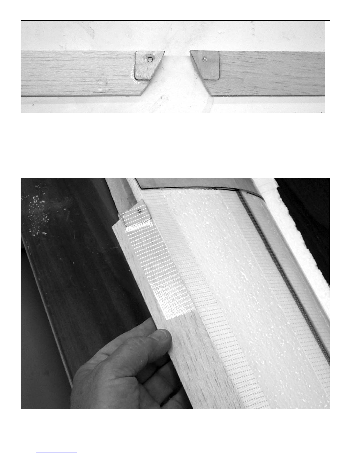
Prepare the ailerons by gluing the laser cut plywood doublers to the
tapered ends. The hole is closer to the edge on the bottom that the top. Tops
are marked with a T. Glue flush with the end and leading edge of aileron.
Run a 9/64” drill through the hole and aileron. Turn the aileron over and
glue the bottom doubler on. Align the hole in the doubler with the hole in the
aileron.
Hinge the ailerons using the bi-directional tape.
Page 16
Ripper
Assembly instructions
16
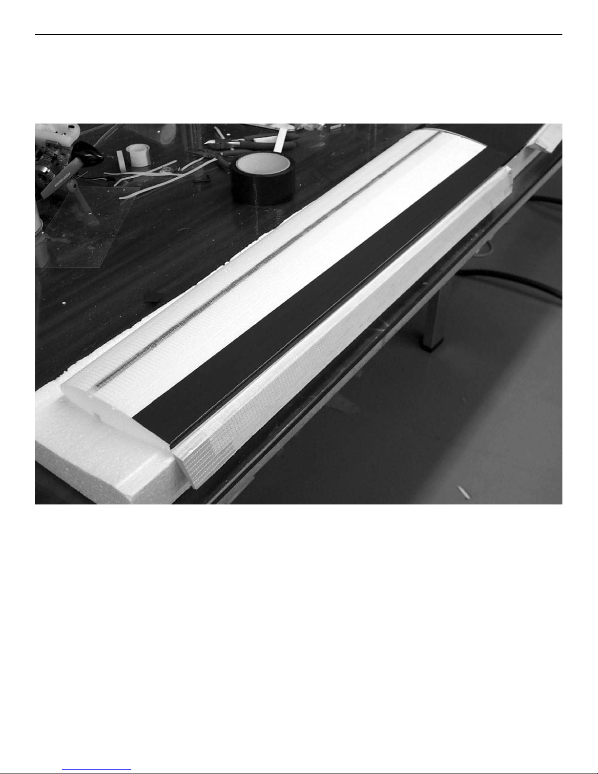
The best way to cover the wing is with packing tape. Most local stores only
carry the clear and olive drab colored tape. It is available in most all colors. On the top, start at the trailing edge of the aileron and simply pull a
piece from the tip to the center section. Have the aileron in the full down
position.The tape is 2” wide, start the next row by overlapping about 1/4” to
3/8” of the row you just put down. Continue on to the leading edge.
On the bottom of the wing start at the trailing edge of the wing. Flex the
aileron down and let the covering go around the trailing edge. You can then
start a piece at the leading edge of the aileron and cover it. Continue forward with the tape to the leading edge.
The other method is to use rip-stop nylon which can be purchased at a cloth
store. You simply cut to the shape of each wing panel and brush clear
polyurehtane onto the cloth. This will result in a tougher wing but will also
weigh more.
Page 17
Ripper
Assembly instructions
17
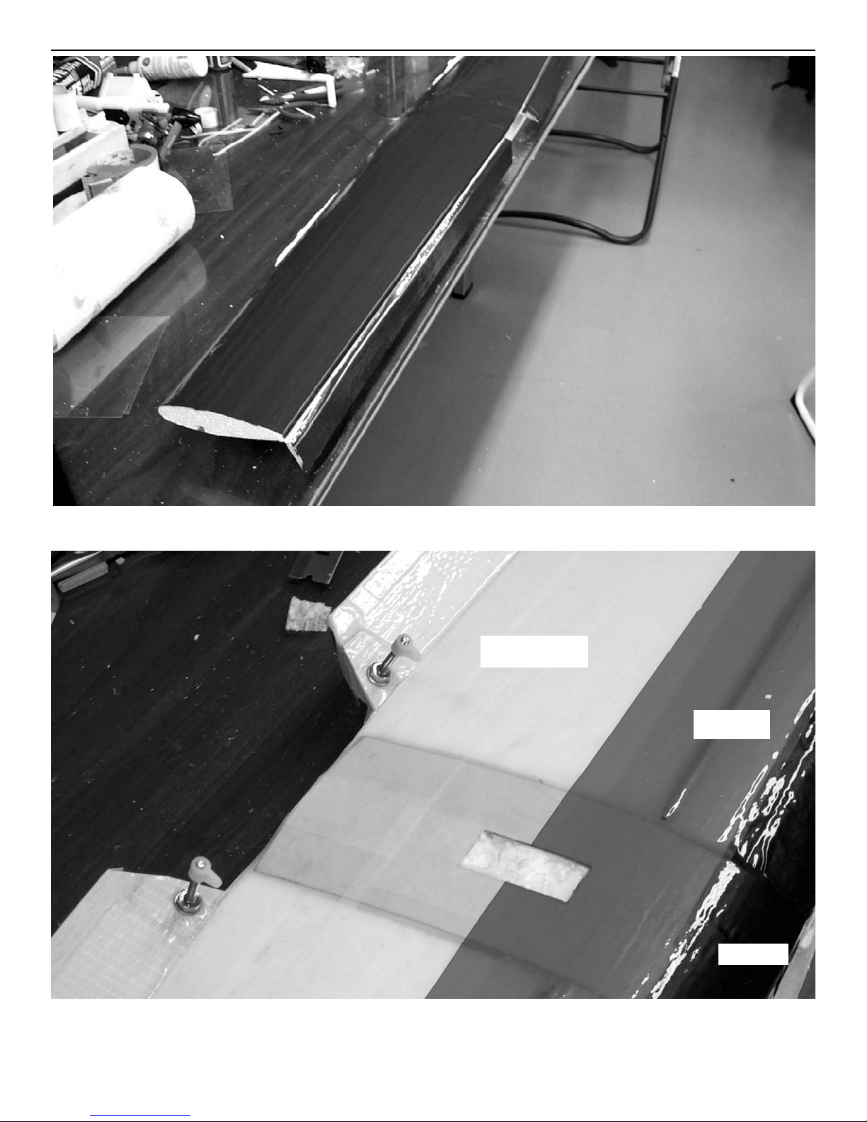
black
Bottom of wing fully covered.
center of wing on top showing three colors of packing tape and aileron
servo cutout. Cover top and bottom in contrasting colors to help you see the
plane better.
white
red
Page 18
Ripper
Assembly instructions
18
Cut the tape from the holes in the
ailerons and install the control
horns. Locate the 6-32 x 1-1/2” bolts
number 6 washers and nuts and the
nylon pushrod fittings. Install the
bolt with a washer on each side of
the aileron and the nut. Put a drop
of CA on the nut to make sure it does
not come loose. Screw the nylon fitting on top flush with the end of the
screw.
finished wing
Page 19
Ripper
Assembly instructions
19
Align the aileron with the end of the wing and lay the angle cut in the leading edge against the trailing edge of the wing( aileron in the full down position). Use a short piece of tape on each end and one in the middle to form the
hinge. Allow the tape to overlap the wing one inch and the aileron one inch.
After the aileron is aligned fill in the spots between the tape with more tape
so the entire top surface is covered. Now fold the aileron over so the top
surface is laying on the top of the wing and apply tape to the bottom of the
aileron allowing it to over lap the wing one inch and the aileron one inch.
Repeat for other wing.
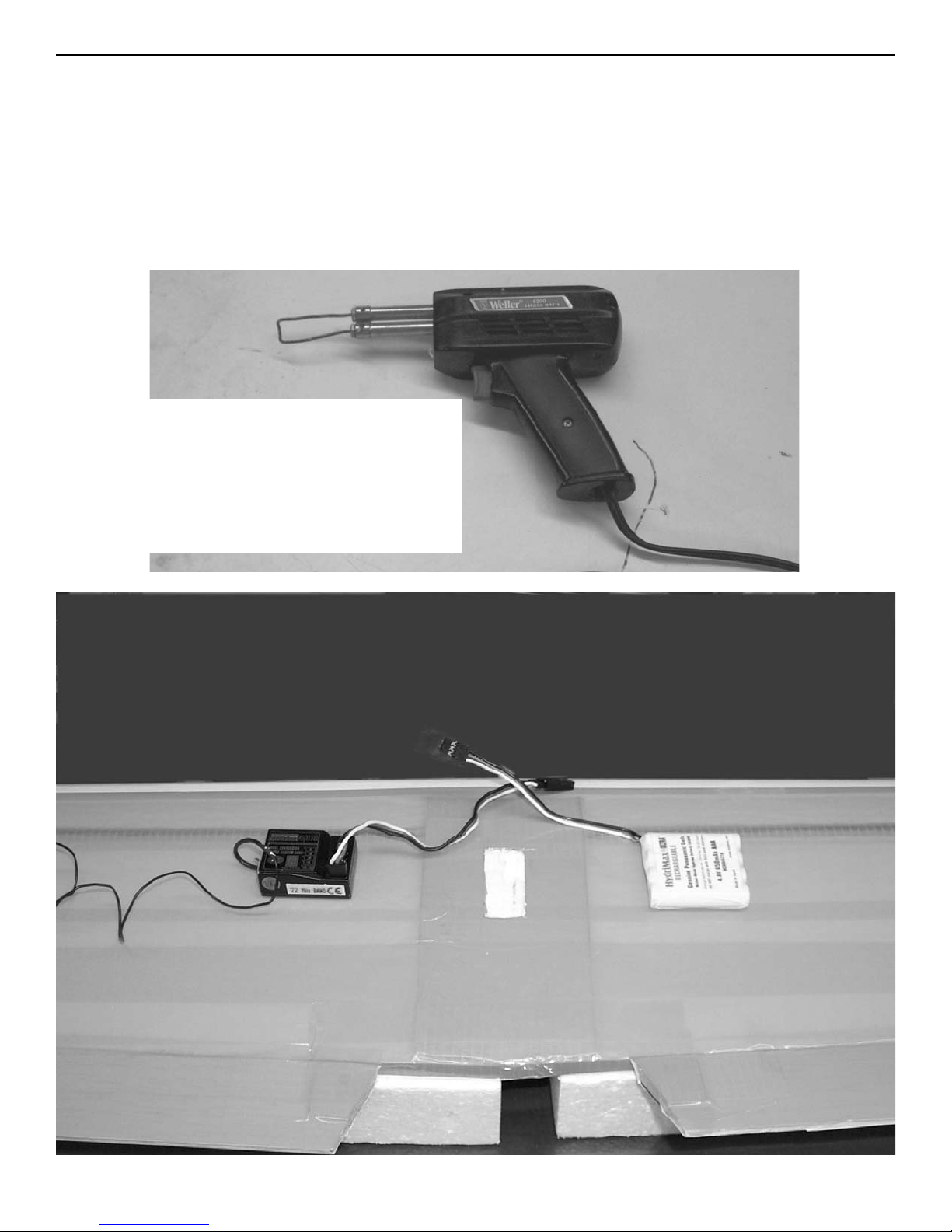
The best way to remove the foam
from the servo, battery and receiver compartment is with a soldering
iron with a piece of #10 copper wire
formed into a loop 3/4” wide which
will just fit into the servo cutout.
Page 20
Ripper
Assembly instructions
20
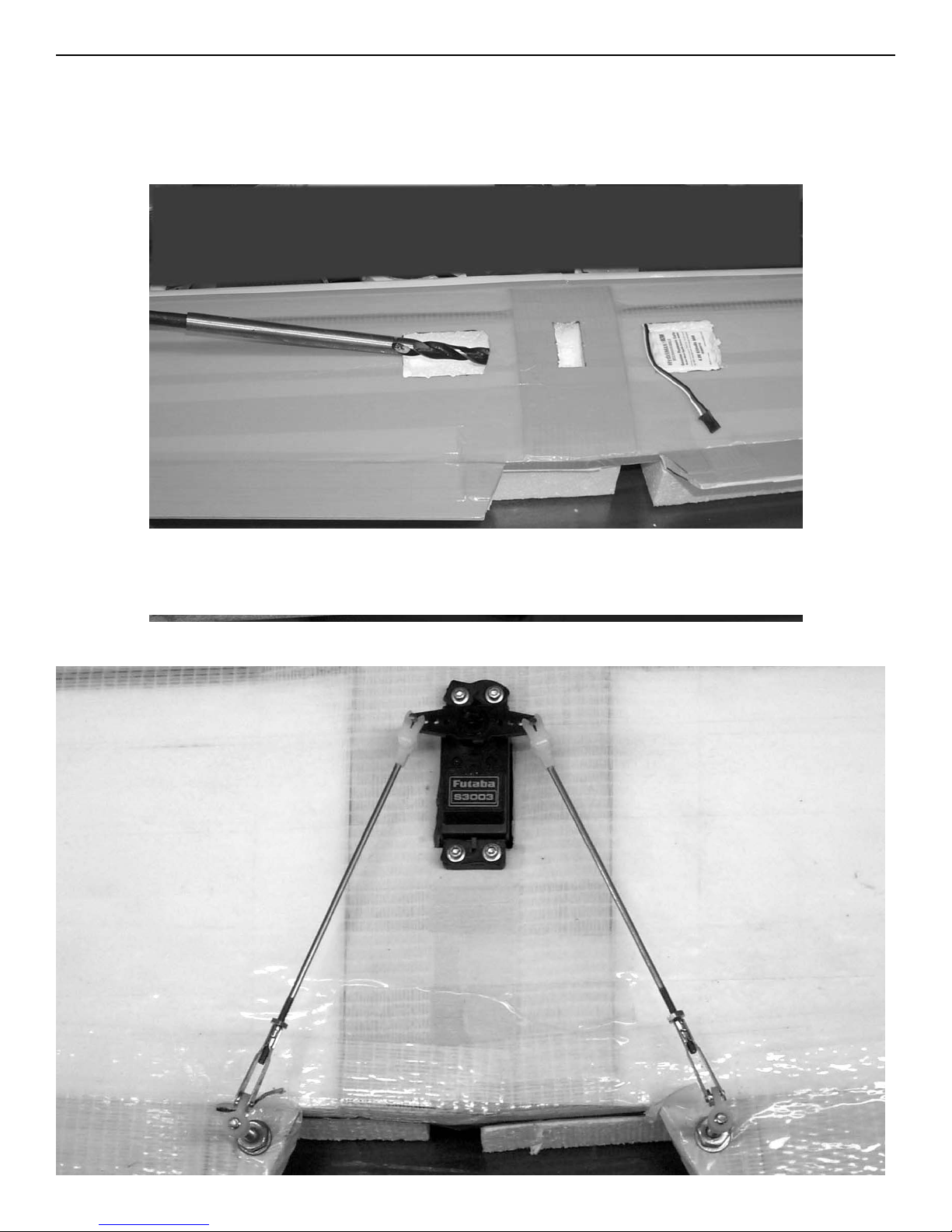
Mount the aileron servo in the cutout and pull the wire into the receiver compartment.
lay out the receiver and battery pack and mark thier location on the wing.
Put the receiver on the left side and the battery on the right side about 1/2”
behind the spar. Use the soldering iron to cut the foam out. Cut just deep
enough for the battery to fit flush with the top of the wing and the receiver
to have room for the wires.
Use a 1/2” drill to make the hole from the receiver compartment to the
aileron servo mount hole.
Page 21
Ripper
Assembly instructions
21
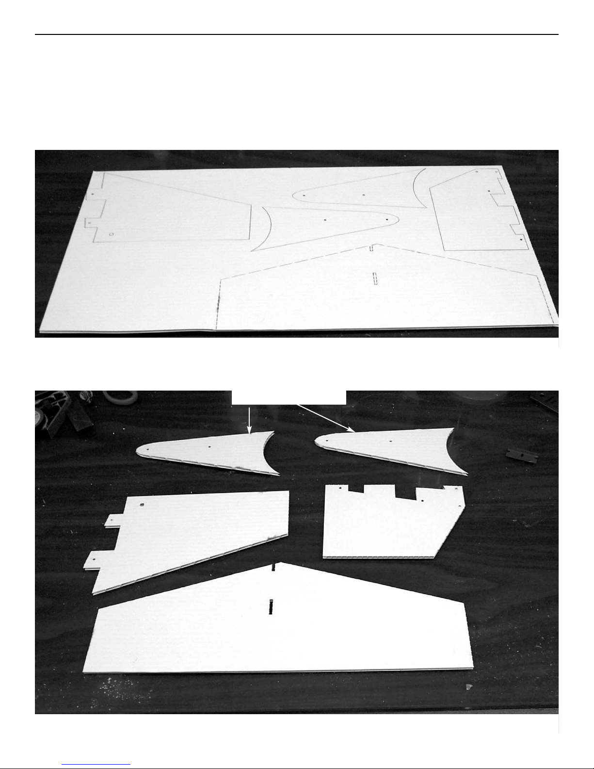
Install a servo arm on the servo and center it. Locate the 2-56 threaded
rods, 2-56 golden clevises and 2-56 nuts. install the nut and clevis and
attach to aileron horn. Measure the wire to the center of the control horn
and bend at 90 degrees. Cut the bend at 3/8” and install in horn. The horn
will have to be drilled out to .078” to accept the rod. Retain on the horn with
the nylon snap-r-keeper. Don’t forget to put the screw in the servo horn.
After adjusting center, install the retainer clip on the clevis.
Locate the coroplast sheet and cut all the parts out using a knife with a #11
blade. If some discoloration is present from the laser cutting, it can be
removed with some solvent or alcohol and a rag. Be careful with solvent and
don’t desolve the coroplast.
With the parts separated, locate the wing tips.
wing tips
Page 22
Ripper
Assembly instructions
22
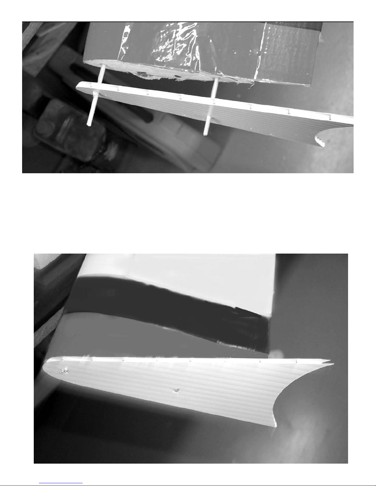
Take one of the bamb0o skewers and cut it into 4 equal pieces align the wing
tip with the leading edge of the wing and insert one of the skewers. Align the
rear hole in the tip to the center of the wing and insert the other skewer.
Push the tip against the end of the wing and mark the outline on the tip.
Remove the tip an apply urethane glue where the wing will contact the tip
and on the wooden skewers. Push the tip flush against the end of the wing
and secure with masking tape till dry.
Page 23
Ripper
Assembly instructions
23
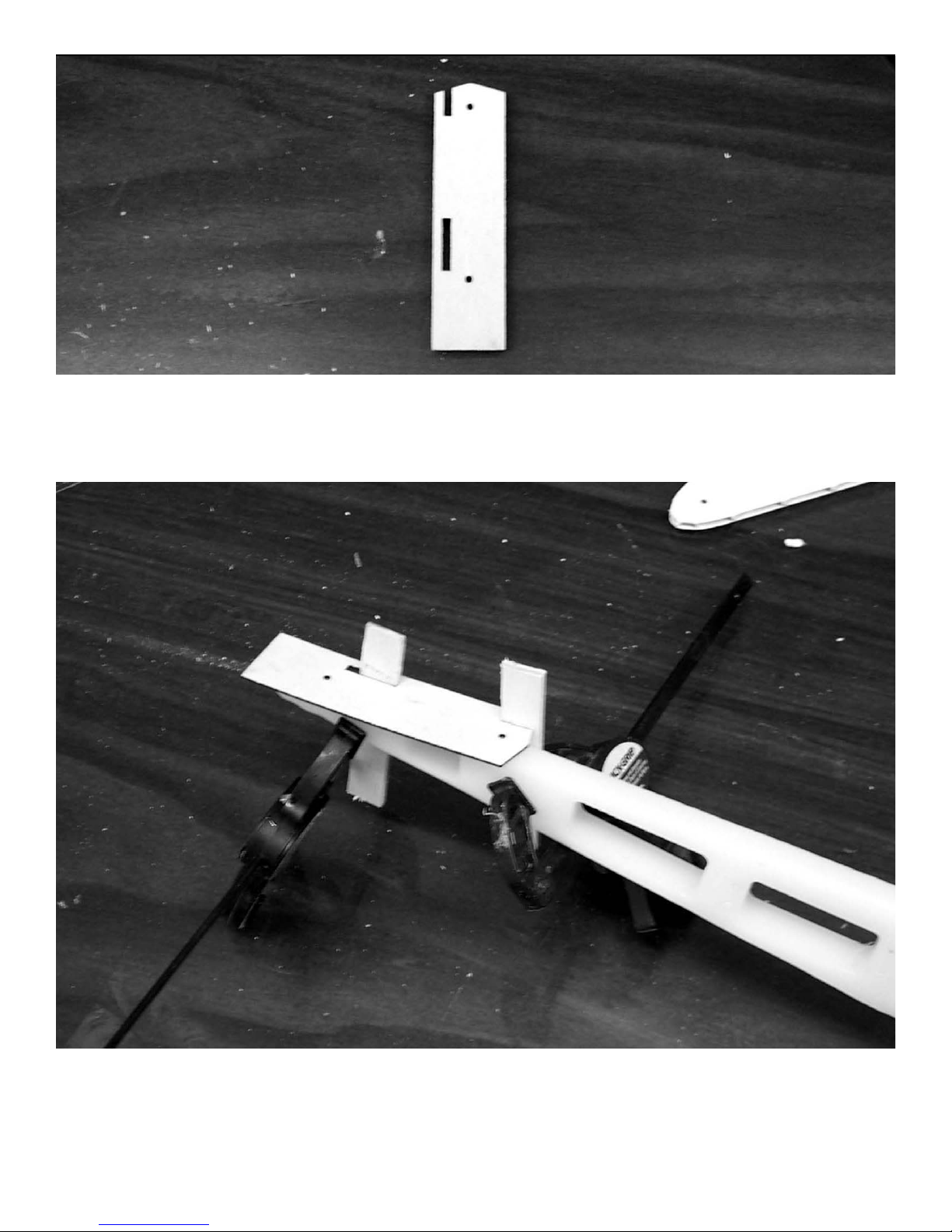
Locate the laser cut 1/16” ply stab
reinforcement plate.
Align the rear edge of the stab reinforcement plate with the rear end of the
fuselage. Insert a scrap piece of wood in the slots and clamp to the fuselage
side. This will insure the fin is square when installed. Drill two 5/64” holes
through the holes in the plywood plate into the fuselage to mount the stab.
Page 24
Ripper
Assembly instructions
24
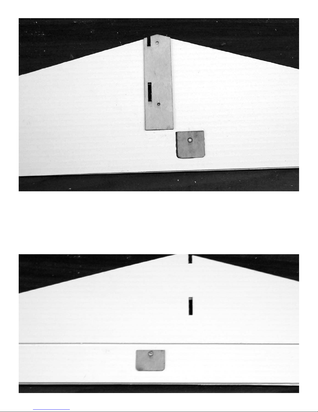
Glue the stab reinforcement plate to the top of the stabilizer. the cutout
for the hinge line goes on the bottom. Align the slots for the fin in the stab
with the slots in the plywood. Glue the elevator horn reinforcement plate
to the top of the elevator, aligned with the rear of the stab reinforcement
plate. Drill a 9/64” hole through the laser cut hole in the plywood reinforcement plate on the elevator. Turn the assembly over and glue the bottom reinforcement plate in place centered over the hole.
Page 25
Ripper
Assembly instructions
25
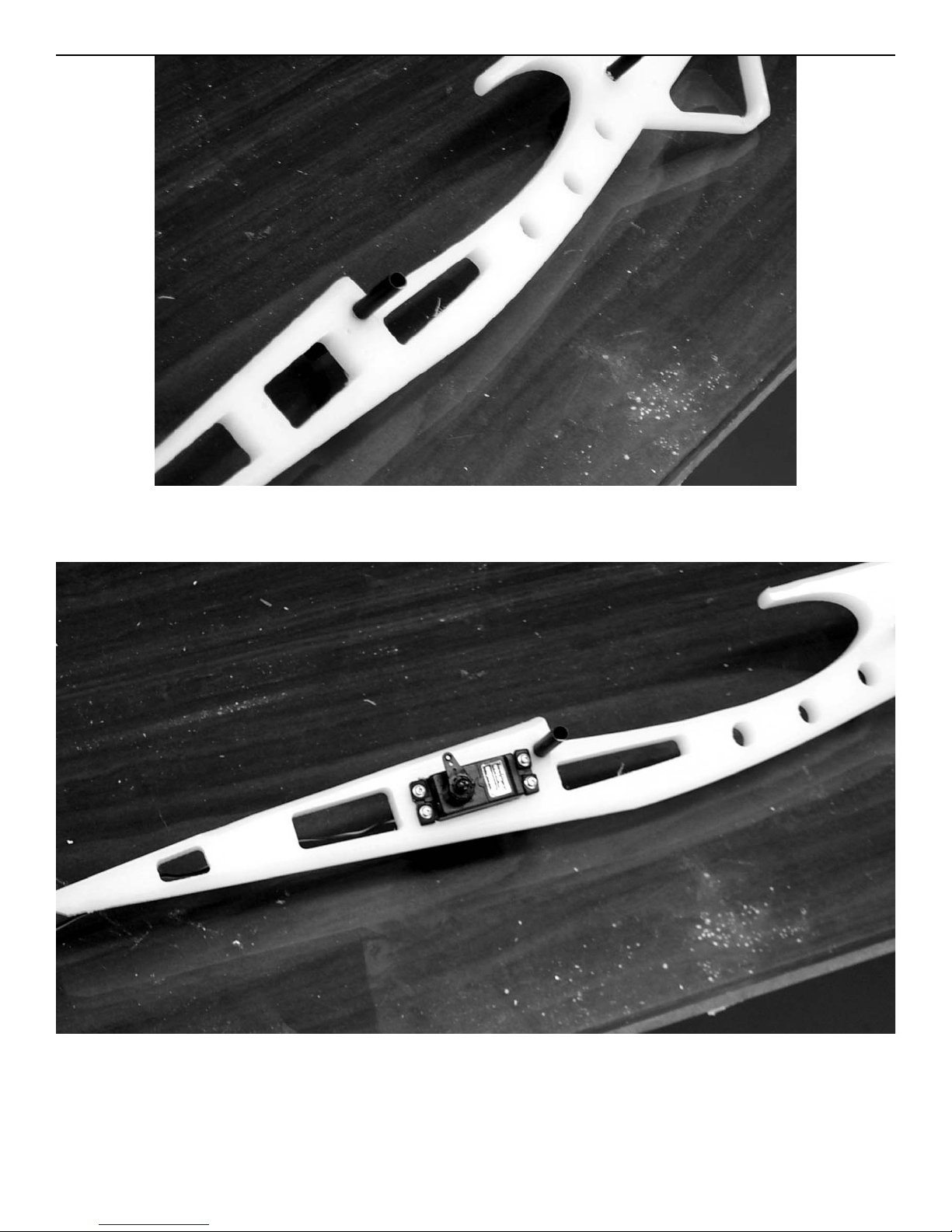
Locate the two 3” epoxy glass dowels and insert in fuselage at the front and
rear of wing saddle. These are a press fit and do not require any glue.
Install the elevator servo in the precut hole at the rear of the wing saddle.
Use the hardware supplied with the radio.
Page 26
Ripper
Assembly instructions
26
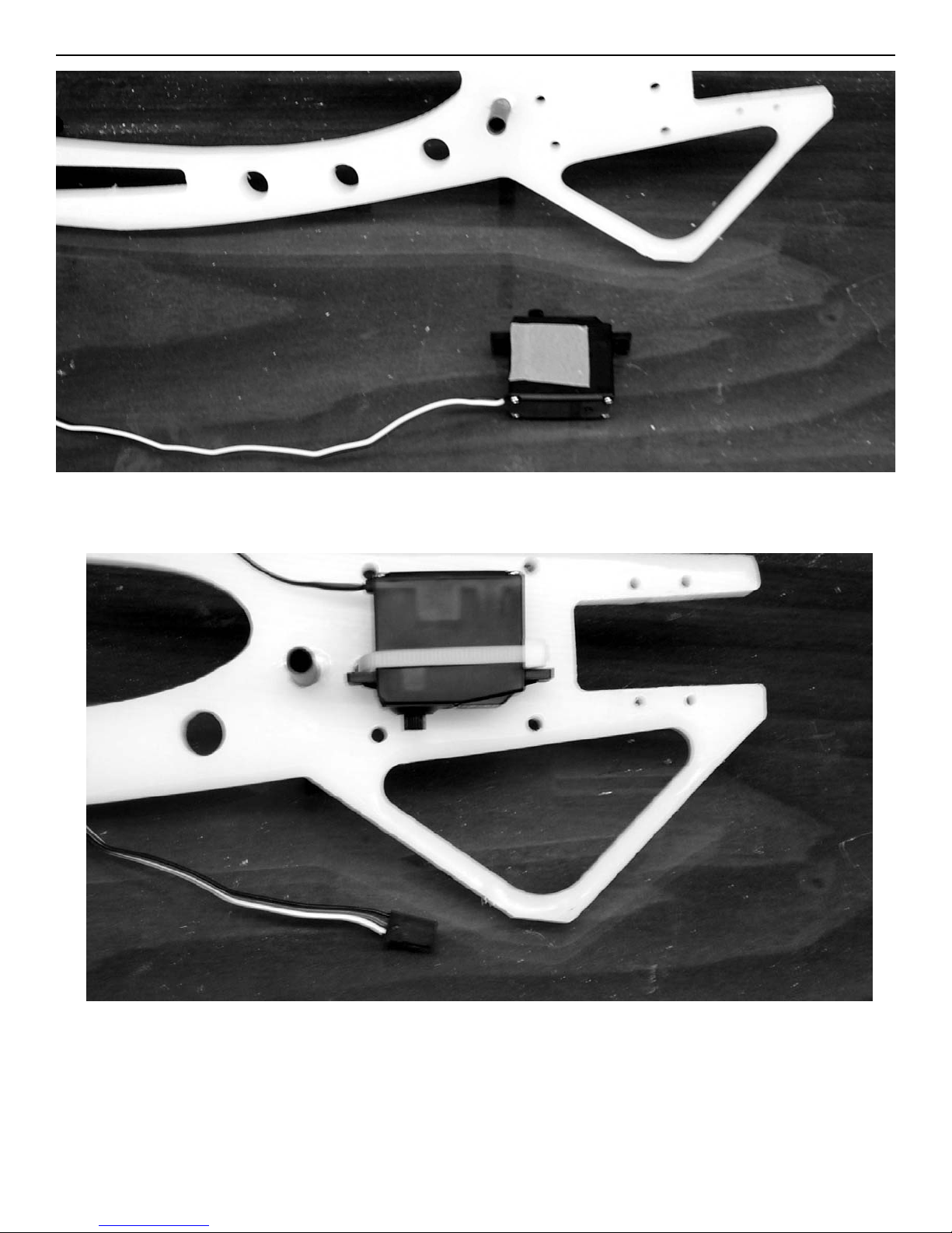
put a small piece of double sided tape ( not supplied) on the throttle servo.
Stick the throttle servo on the side of the fuse centered between the
predrilled holes with the hole just at the bottom of the mounting lugs,and
secure with a cable tie through the predrilled holes.
Page 27
Ripper
Assembly instructions
27
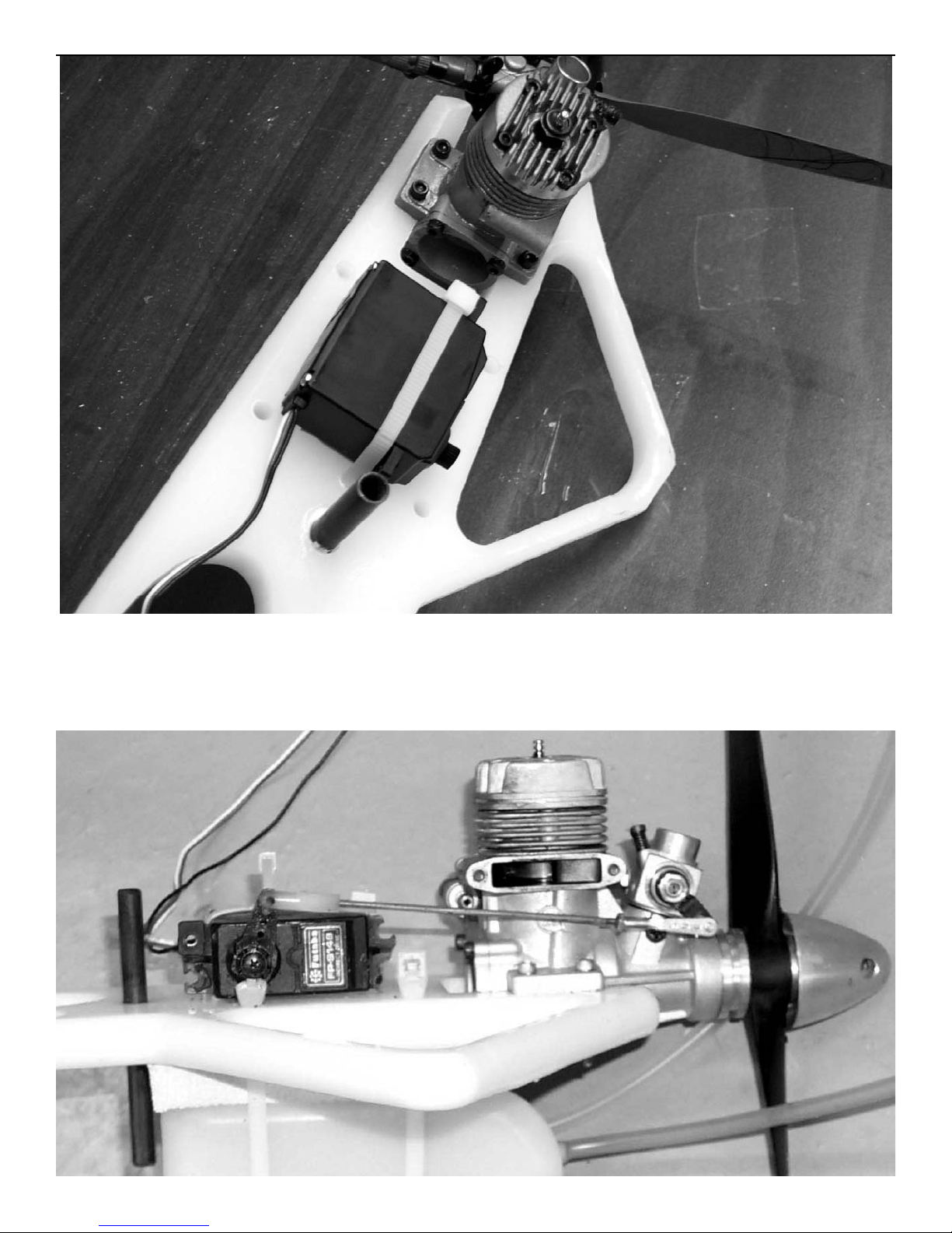
Center your engine in the mounts and mark the mounting hole locations.
Drill a 1/8” hole at the marks and mount the engine using 4-40 bolts and lock
nuts (not supplied).
Page 28
Ripper
Assembly instructions
28
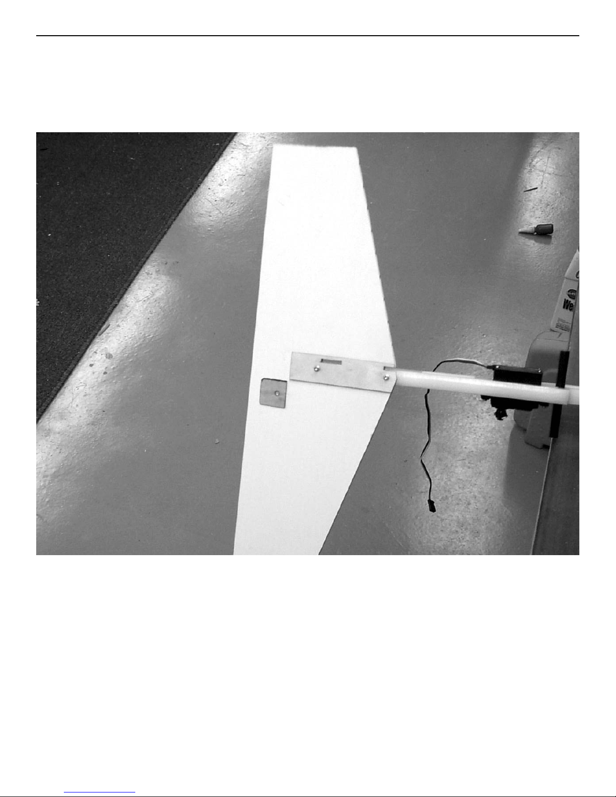
Locate the 2-56 threaded rod , the 2-56 golden clevis and nut. Install the nut
and clevis and attach to the throttle arm on the motor. With the throttle
fully open and the servo at high motor, mark the location of the bend in the
rod and bend at 90 degrees. Cut off at 3/8” and attach to servo using the
nylon snap-r-keeper. the servo arm will have to be drilled out to .078”.
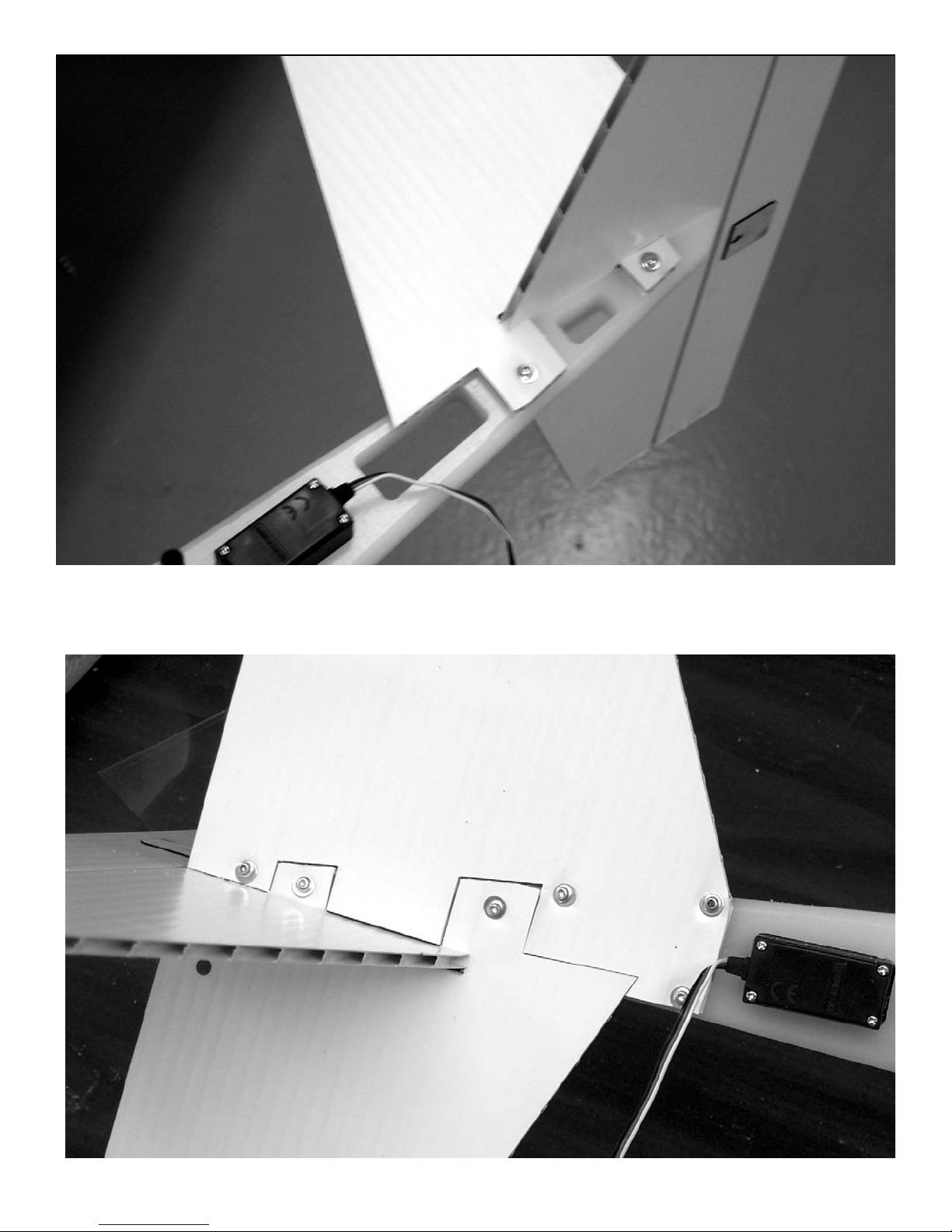
Mount the stab to the fuselage using two #2x3/4” screws with #4 washers
under the heads.
Page 29
Ripper
Assembly instructions
29
Insert the fin through the holes in the stab and drill a 5/64” holes at the
two mount locations. Mount the fin using #2x1/2” screws and #4 washers
under the heads.
Page 30
Ripper
Assembly instructions
30
Fit the sub-fin in place and drill 5/64” holes at the 4 mount locations. Mount
sub-fin using four #2x1/2” screws and #4 washers under the heads.
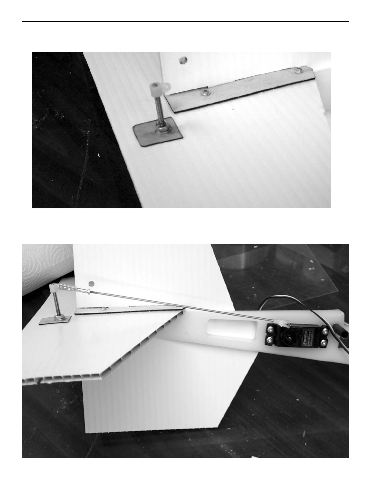
Install the elevator horn ( 6-32x1-1/2” screw) with a washer on both sides
and secure the nut with a drop of CA glue. Screw the nylon fitting on the
end flush with the end of the bolt.
Page 31
Ripper
Assembly instructions
31
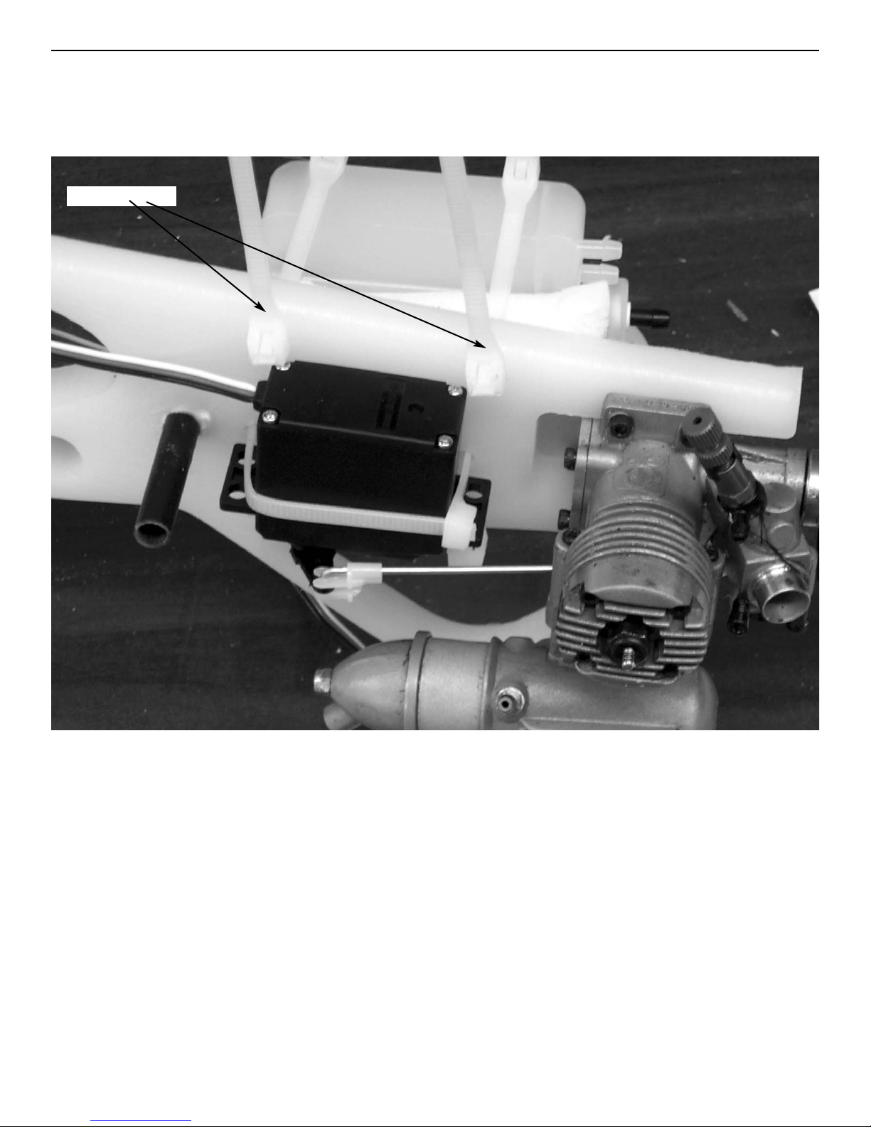
Locate the 2-56 threaded rod and golden clevis and nut. Attach to elevator
horn and center the servo. Bend the rod 90 degrees and cut off at 3/8”.
Attach to servo with the nylon snap-r-keeper.
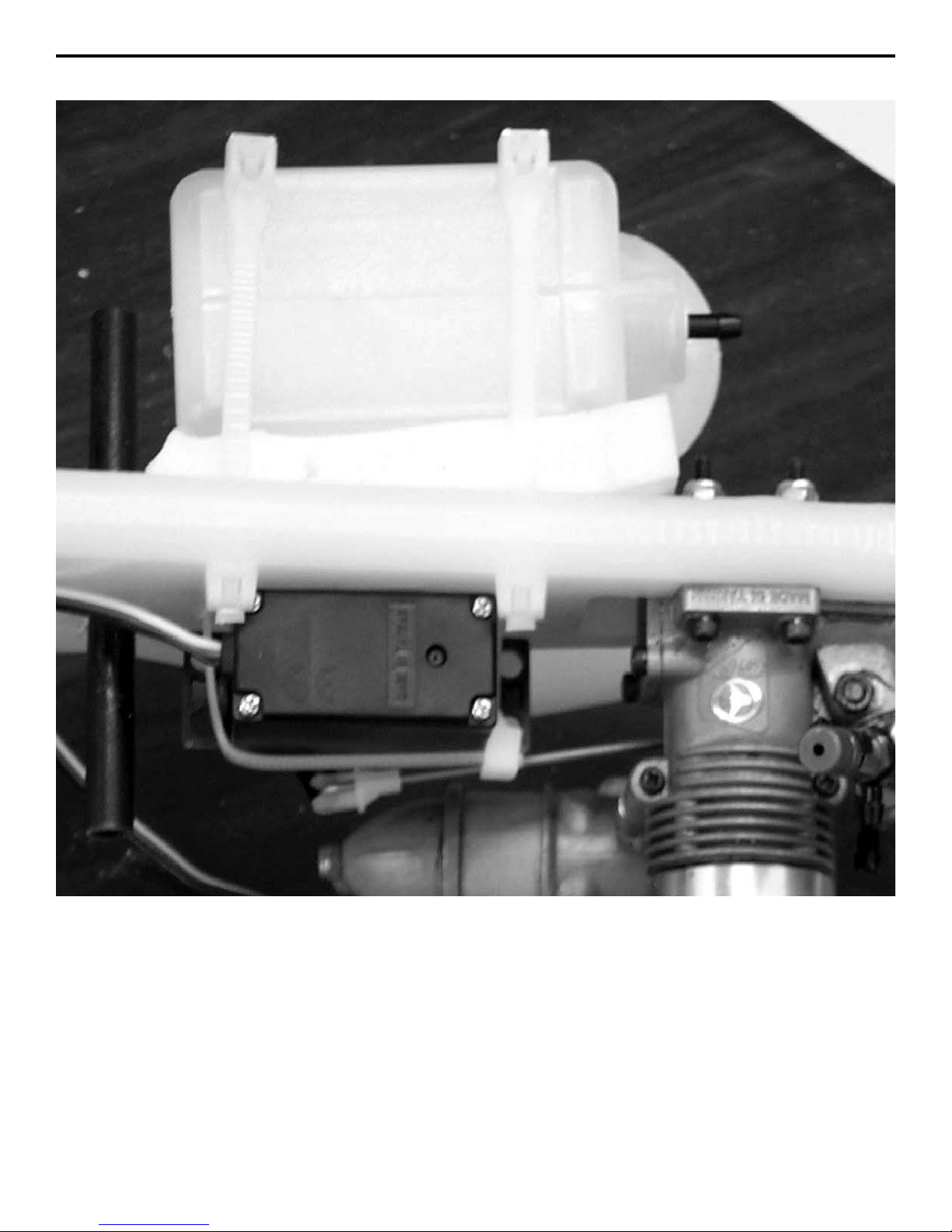
The cable ties that mount the tank do not go all the way around the fuselage. Insert one through the holes on the bottom, around the tank and back
through the holes on the top side. Use another tie wrap to secure the end
and clip using just the end of the tie wrap.
clip here
Page 32
Ripper
Assembly instructions
32
Use a piece of 1/2” foam under the tank and do not pull the tie wraps tight.
Leave loose so as not to cause bubbles in the tank.
Page 33
Ripper
Assembly instructions
33
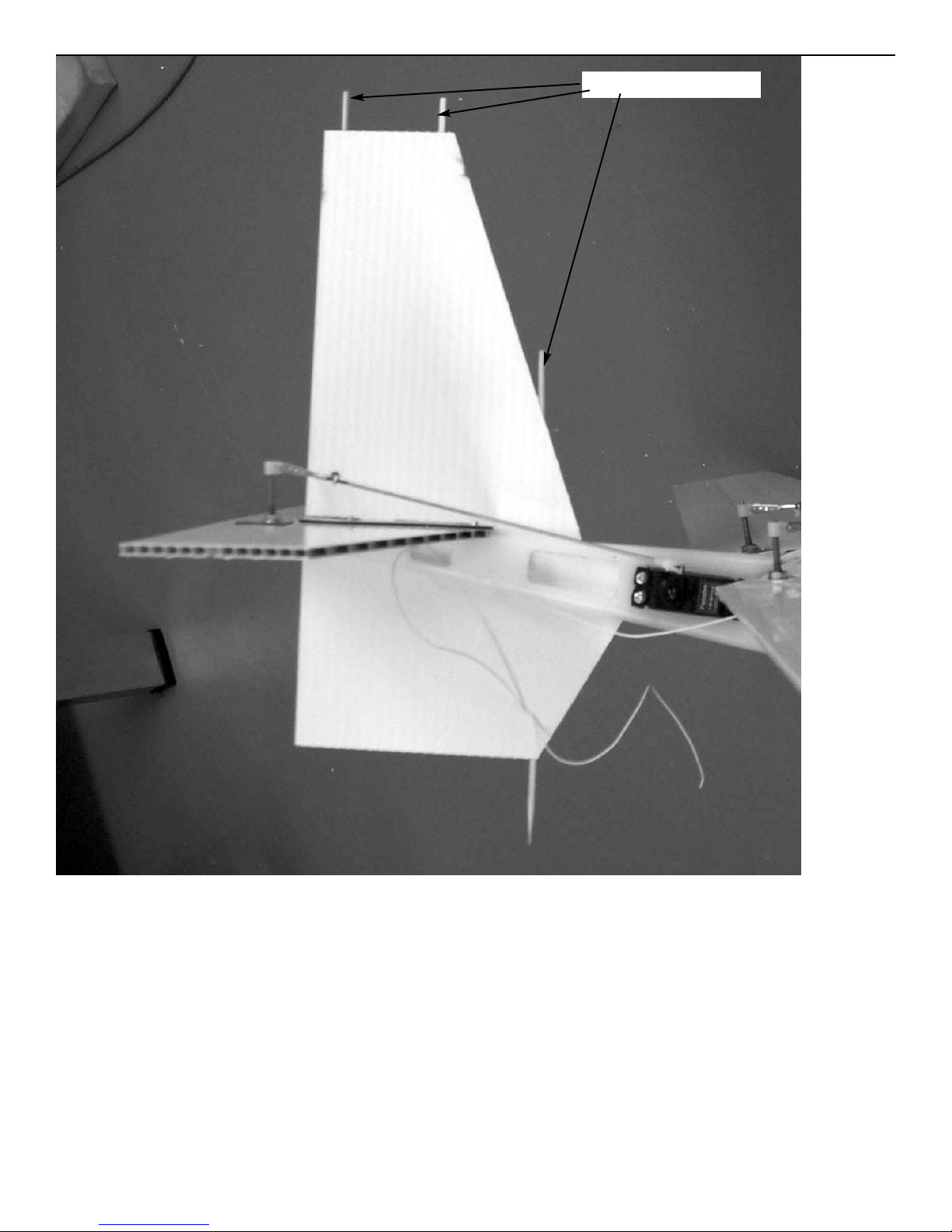
Locate the other 3 skewers and install in fin, sub-fin assembly. The skewers
should go from the top, through the stab and into the sub-fin. If you have a
long 1/8” drill you can drill through the stab from the top of the fin. If not
mark the location of the holes, remove the fin and drill a hole in the stab so
the skewers can pass through. Apply a drop of CA at one end of the skewer
to prevent it from backing out. Do not glue to stab so if you need to replace
the fin or stab during a match it will be a matter of a couple of screws coming out.
skewers
Page 34
Ripper
Assembly instructions
34
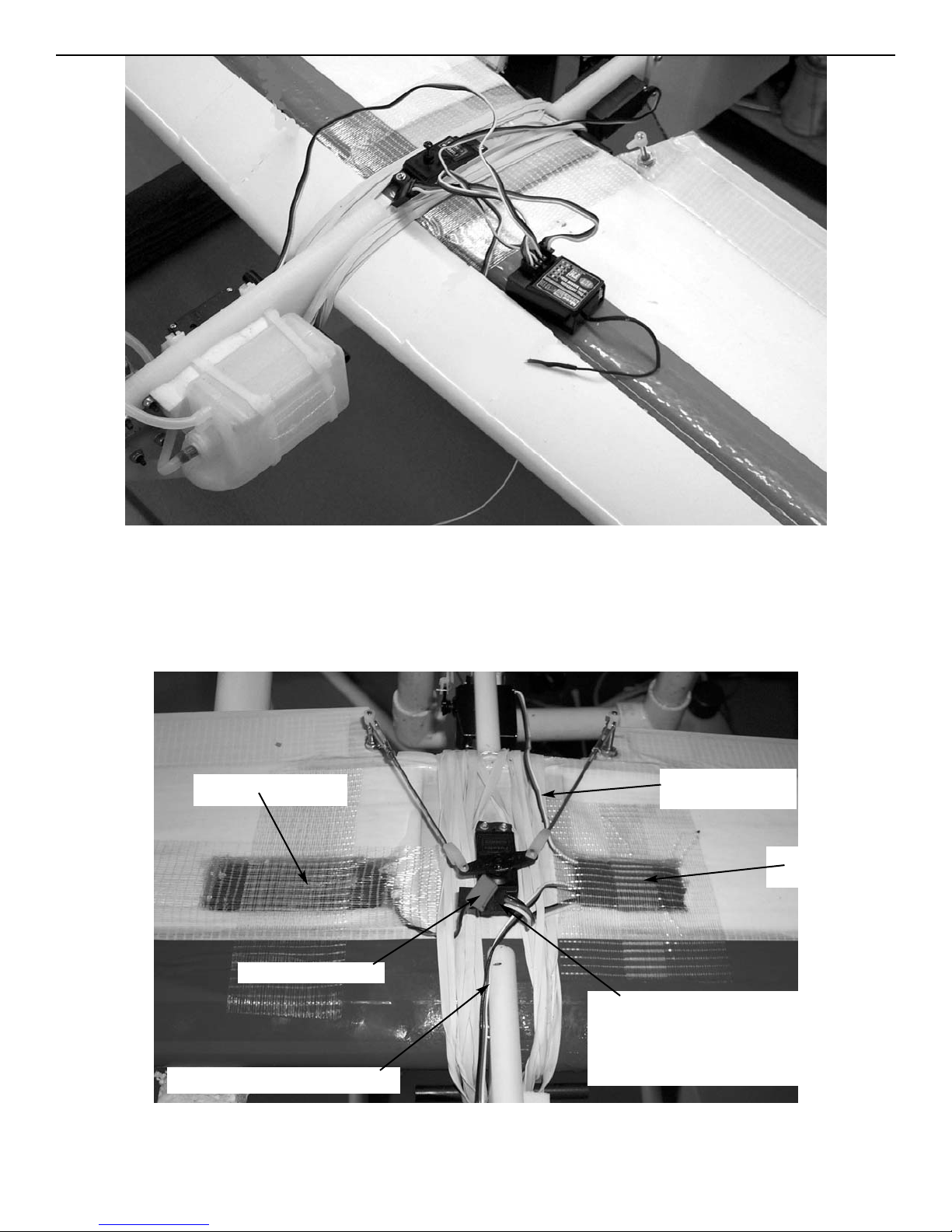
Place wing in saddle and secure with at least 6 #64 rubber bands on each
side. Plug the aileron lead, elevator lead and throttle lead into the receiver. Drill a 5/64” hole in the bottom of the receiver compartment and pass the
receiver antenna through to the bottom of the wing. Plug a 6” extension into
the battery terminal on the receive, we will not be using a switch.
Place receiver in compartment with foam and tape in place. The throttle
servo wire and elevator servo wire can be held in place with another rubber
band.
battery lead
6” extension pluged into
receiver. Plug into battery
when ready to fly.
receiver
elevator
servo lead
battery
throttle servo lead
Page 35
Ripper
Assembly instructions
35
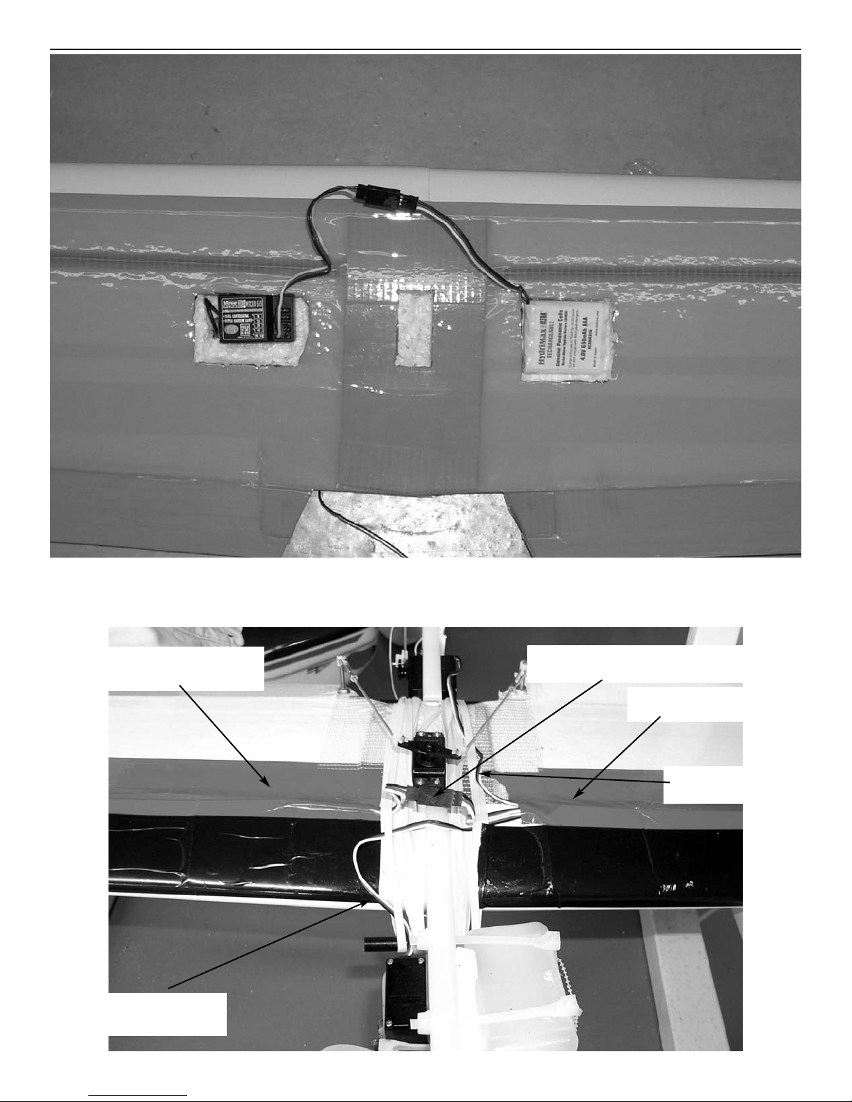
Install the battery in the other wing and tape down. The wire can be secured
under one of the rubber bands.
receiver
compartment
battery
compartment
receiver power lead
plugged into battery lead
throttle servo
lead
elevator
servo lead
Page 36

Ripper
Assembly instructions
36
The CG should be between 2-1/4” and 2-3/4”. If set up as shown, it should be
fine with no weight added. I have use O.S. LA.15. Thunder Tiger .15, Mecoa .15
and all were fine with no added weight. Some have added weight to the tail to
make the plane more sensitive on elevator. You can adjust to your flying
style. The elevator throw should be set up so you can do loops without snapping out. I have found that 1/2” throw works out about right. If you cannot
do loops without snapping out, adjust throw. the ailerons work really well
with 3/4” throw on high rate and 1/2” on low rate.
Page 37

Ripper
Assembly instructions
37
Parts price list
1. Fuselage HDPE $34.95
2. Wing Kit CORES, SPARS, SPAR JOINERS, AILERONS,
WING TIPS,LEADING EDGE REINFORCEMENTS,
1/32 PLYWOOD DOUBLERS $39.95
3. Wing Cores each $10.00
4. Spars EPOXY GLASS each $3.95
5. Leading edge reinforcement covers each $6.95
6. Ailerons Balsa each $1.95
7. Laser cut 1/32” plywood doublers set $4.95
8. Laser cut 1/16” stab reinforcement $1.00
9. Bamboo skewers each .10
10. Spar joiners each .75
11. Coroplast wing tips each $1.50
12. Coroplast stab $3.95
13. Coroplast fin $2.95
14. Coroplast sub fin $2.50
 Loading...