

Page 1
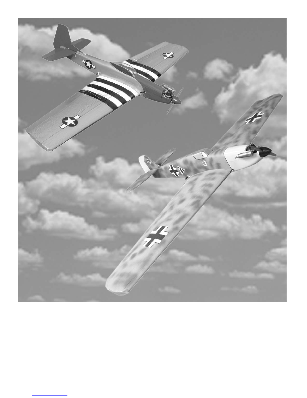
Building Instructions
P-51 BF109
Sport model for .015 engines. Legal for SSC Warbird
Lanier R/C Inc. P. O. Box 458 Oakwood, Ga. 30566
Copyright 2004 Lanier R/C Inc.
Page 2

Warbird Combat
Assembly instructions
2
Introduction
Thank you for purchasing the Lanier R/C Warbird Combat Plane. We
believe we have one of the best combat designs for SSC available. It is
very fast to build, and be very sturdy in combat. The flight charatristic
of the plane allow you to be very aggressive because you can concentrate on your opponent and not on keeping the plane in the air. The roll
rate is very quick, allowing you to quickly change from one knife edge
to the other and be on your opponent very quickly. So get on with construction and go get some streamers.
The construction of the two planes is exactly the same so some of the
pictures will be of the P-51 and others will be of the BF109. The shape
of the parts will vary but just follow the instructions for that particular part.
Important information:
Please inspect the plane before beginning to assemble to make sure you are
happy with it. After assembly has begun you cannot return the kit. If you find
a problem before beginning to assemble the plane you must contact us,
please do not return to the dealer.Lanier R/C is proud of the care and attention that goes into the manufacture of parts for its model kits. The company
warrants that for a period of 30 days, it will replace, at the buyers request,
any parts or material shown to the company’s satisfaction to have been
defective in workmanship or material at the time of purchase.
No other warranty of any kind, expressed or implied, is made with respect to
the merchandise sold by the company. The buyer acknowledges and understands that he is purchasing only a component kit from which the buyer will
himself construct a finished flying model airplane. The company is neither
the manufacturer of such a flying model airplane, nor a seller of it. The
buyer hereby assumes the risk and all liability for personal or property damage or injury arising out of the buyers use of the components or the finished
flying model airplane, whenever any such damage or injury shall occur.
Any action brought forth against the company, based on the breach of the
contract of sale to the buyer, or on any alleged warranty there under, must
be brought within 1year of the date of such sale, or there after be barred.
This one year limitation is imposed by agreement of the parties as permitted by
the laws of the state of Georgia.
Page 3
Warbird Combat
Assembly instructions
3
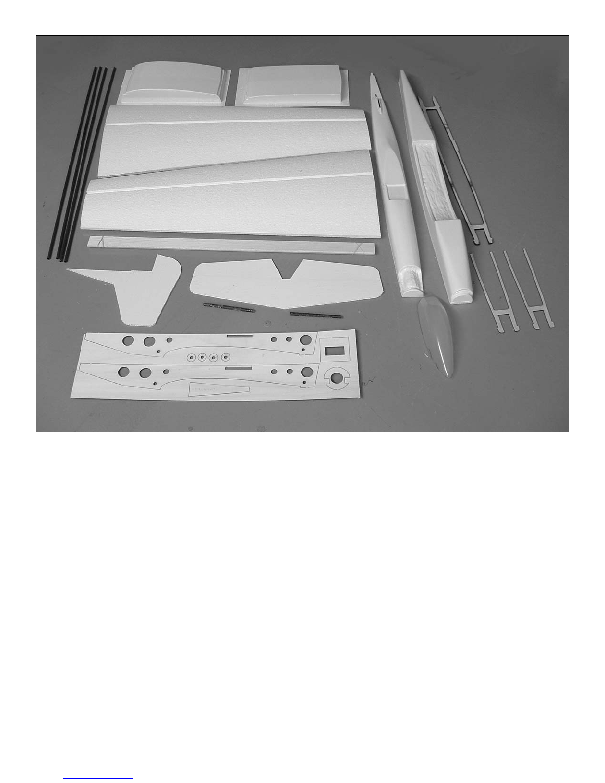
Parts list
1. Wing panels 2
2. Epoxy glass spars 4
3. Balsa Ailerons 2
4. Vacuum formed fuse halves 2
5. epoxy glass wing dowels 2
6. Coroplast Stab 1
7. Coroplast Fin 1
8. 1/8” Laser Cut Sheet 1
Stab mount (1)
Fuselage sides (2)
Nose ring (1)
Wing dowel doublers (2)
Elevator servo mount (1)
9. 1/4” Fuselage center support 1
10. 1/8” laser Cut Motor Mounts 2
11. Vacuum formed wing center doublers 2
12. Clear canopy (P-51 only) BF 109 has no canopy
13. Throttle servo mount
14. bamboo skewers 2
15. hardware bag
P-51 shown
Page 4
Warbird
Assembly instructions
4
Wing
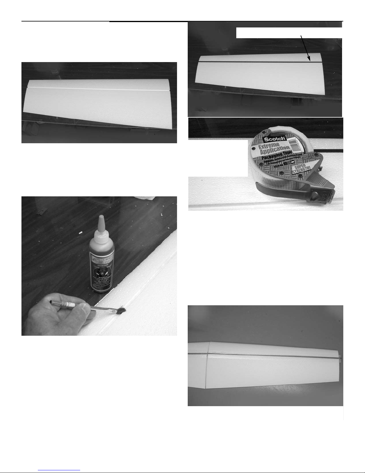
Begin construction with the wing.
Remove the wing panels from their
cores and lay aside.
Using urethane glue or epoxy, glue
the epoxy glass spars in each panel.
If you use urethane glue, don’t over
do it because it expands as it dries.
Brush a lite coat in the spar slots.
Butt the wings together and block
the tip up 1-1/8” to give the proper
dihedral.
3M extreme
application bidirectional
tape
Use b-directional tape to secure the
spars in the slots while the glue
dries. This will also keep the urethane glue from expanding out on
the wing. Stop the tape 2” from the
center of the wing so the spars can
be joined by the center doubler
later. Glue all four spars in the
slot on both wings. You can also use
clear duct tape which is available at
Home Depot and Lowes.
stop tape 2” from center
We recommend using pro-bond urethane glue which can be purchased
at most any hardware store or building supply such as Home Depot or
Lowes. Another name is Gorilla glue
which is the same thing.
Using the urethane glue, run a bead
down the entire length of the spar
slots and use a brush to make sure it
coat the sides and bottom.
Page 5
Warbird
Assembly instructions
5
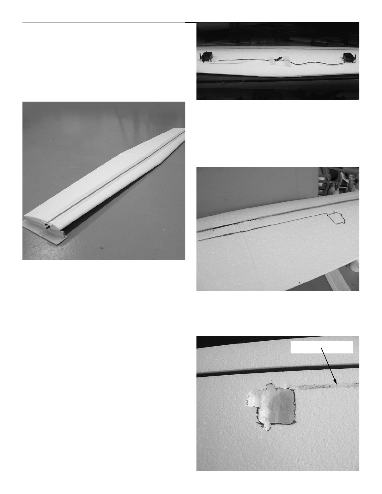
Make sure the left and right panel
are perfectly aligned with each
other and laying flat on the table.
Lay a piece of wax paper over the
center of the root so the glue does
not stick the panel to the table when
gluing together. Mix some 5-minute
epoxy and spread on the root of both
wing panels. Place the panels flat
on the table with the tip blocked up
and use masking tape to hold the panels together till the epoxy sets
The wings are flat bottomed, Lay the
cores on a flat surface with the
roots butted together, if your table
is not straight your wings will not be
straight. You may have to shim one
side to make sure the two halves are
perfectly even with each other.
Layout the position of the aileron
servos on each wing panel. The front
edge of the servo should be 1” behind
the spar. The servos should be out
from the center of the wing by the
length of the servos wire.
Use a sharpie marker and mark
around the servo and down the
length of the wire.
slot for wire
Page 6
Warbird Combat
Assembly instructions
6
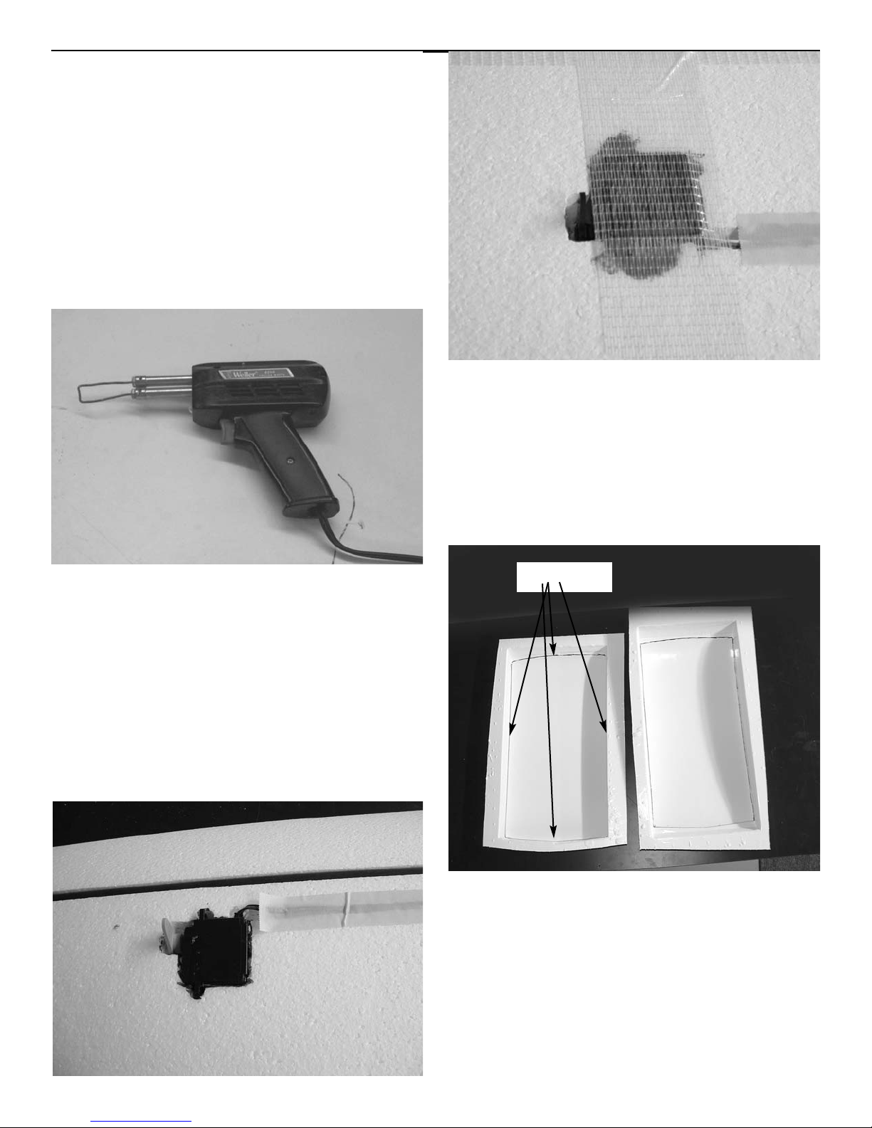
The easy way to remove the foam
from the aileron cutout and the
servo wire channel , is with a soldering iron with a piece of #10 copper
wire bent and formed into a loop.
Make the end 3/4” wide and it will be
just right for the servo cutout. If
you don’t have a soldering iron you
can just dig it out with a knife.
Cut the hole so the servo will be
tight in the hole. It will be held in
place by the foam itself.
Fit the servo in the hole and run the
wire down the channel to the center
of the wing. Use masking tape over
the channel to hold the wire in
place.
you must center your servo with the
arm in place before installing the
servo because you cannot get to it
after it is installed.
Make a cut out to clear the control
horn.
Press the servo into the slot, if necessary use silicone rubber glue on
each end to make the servo tight so
there is no movement. Use a piece of
the bi-directional tape over the
servo to secure in place. Repeat for
the other wing.
locate the two vacuum formed center wing covers. They still have the
flanges on them, so will need to be
trimmed at the bottom edge of the
flange. The covers have the dihedral
molded in so there is a top and bottom.
Trim
Page 7
Warbird Combat
Assembly instructions
7
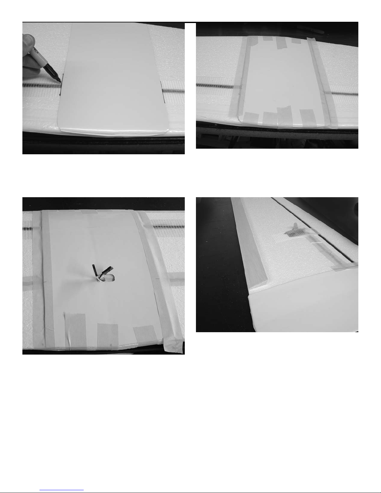
locate the bottom cover, dihedral
proper way, and center it on the
wing. Mark a line down both sides.
Locate the top cover and mark the
location of the aileron plugs and
cut a hole to pull them through.
Also mark down each edge. Remove
the covers lightly sand the inside
with 150 grit sandpaper. Mix some 30
minute epoxy and spread on the inside
of the cover. Lay a bead of epoxy on
top of the spars on both sides. Be
sure the spars and the area of the
cover that they contact have plenty
of glue, the spars are not joined in
the middle other than the doubler.
Use masking tape to hold the covers
in place, both top and bottom, till
the epoxy sets.
Locate the ailerons and align with
the trailing edge of the wing. The end
should be 1/2” out side the edge of
the center doubler.
Page 8
Warbird Combat
Assembly instructions
8
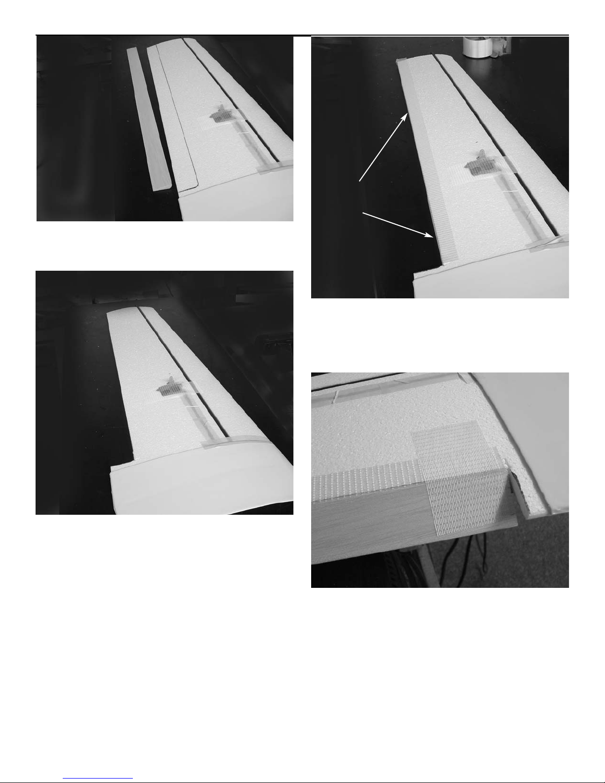
mark the location of the aileron
using your sharpie marker.
Use a straight edge and a single
edged razor blade and remove the
foam along the line.
Use the bi-directional tape and run a
piece down the trailing edge of the
wing wrapping around to the bottom
side.
The ailerons are hinged using the bidirectional tape. Cut a 3”piece and
attach to the aileron at the center
end with 1/2 extending past the leading edge. Fit the angle on the leading
edge of the aileron against the wing
trailing edge. This will have the
aileron in the full down position.
Leave 1/16” clearance from the center section of the wing.
bi-directional
tape
Page 9
Warbird Combat
Assembly instructions
9
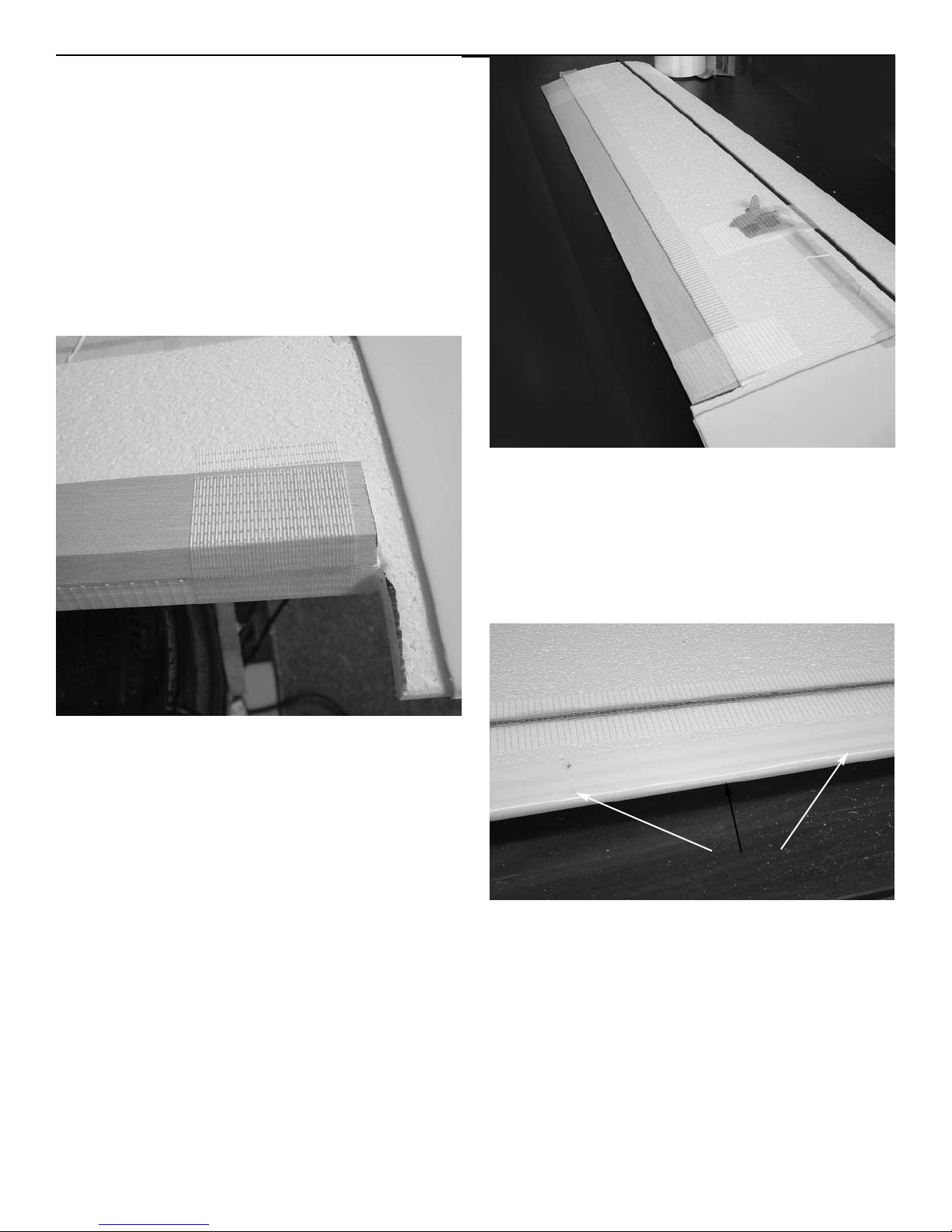
Repeat the hinge taping at the tip of
the wing making sure to keep the
aileron tight against the wing trailing edge. The tip hinge tape should be
1-1/2” from the end of the aileron so
that when you cut the tip to shape
you do not cut away the hinge.
Add three more hinges evenly
spaced between the root and tip for
a total of 5 hinges.
After all five hinges are installed
on the top side, flip the aileron all
the way over till the top surface of
the aileron is laying flat on the top
of the wing.
Now add 3” pieces of tape to the bottom side at the same locations as the
tape on the top side. Put the tape
even with the trailing edge of the
aileron and pull it tightly around
the trailing edge of the wing.
The aileron is now hinged with no
gap on the top surface. The trailing
edge of the wing is thicker than the
aileron on the bottom but at the
speeds the .15 size plane flies it is
not a problem.
Filament tape
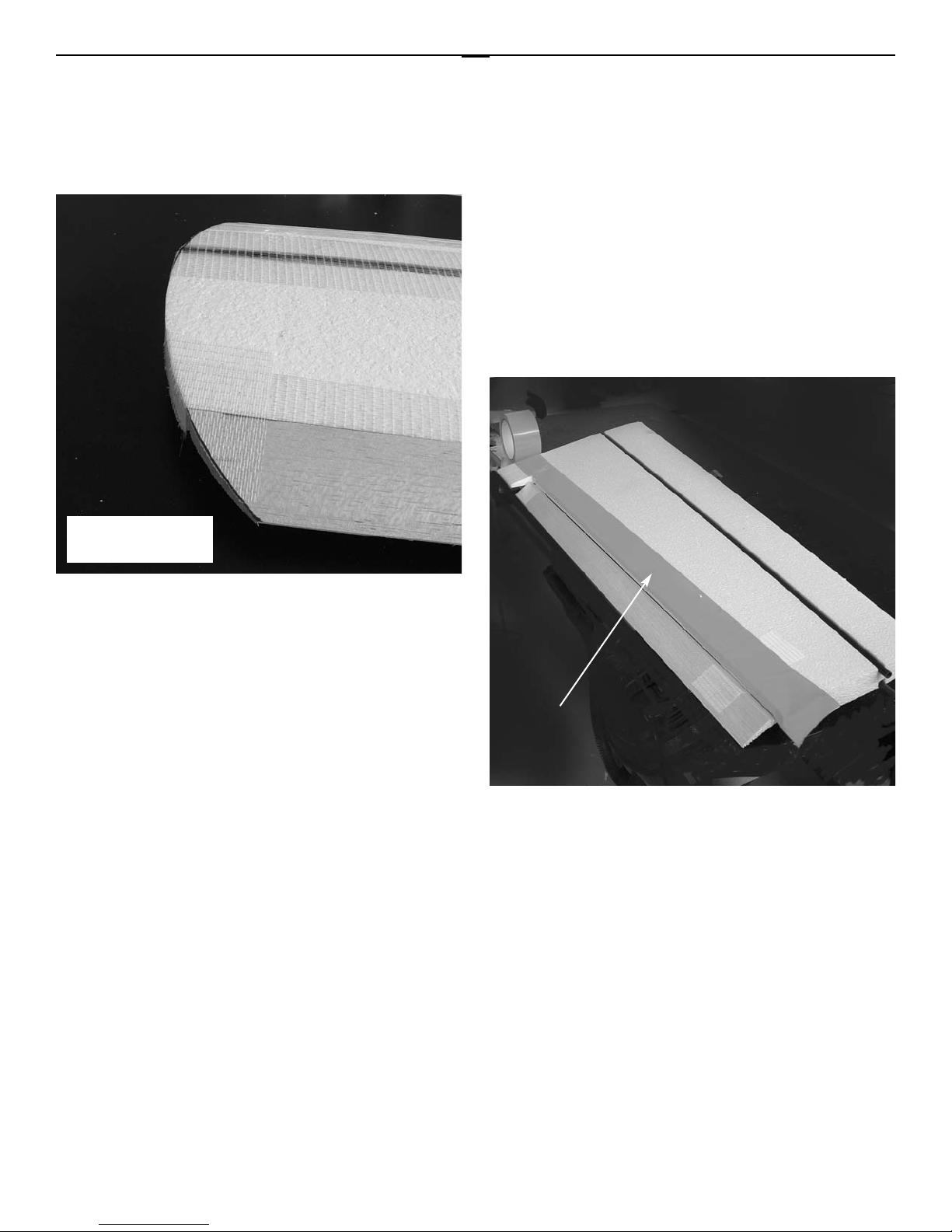
If you plan to only use the plane for
sport flying you may want to skip this
step. The filament tape added to the
leading edge is for protection in collisions from combat. The tape add
weight so for sport flying you don’t
need it. For the combat planes add
four rows of 3/4” filament tape.
Start with one down the center of
the leading edge. Then put one on the
top of the wing overlapping the center piece 1/8”. Now add one to the
Page 10
Warbird Combat
Assembly instructions
10
bottom surface of the wing overlapping the center piece by about 1/8”.
Now add another piece down the center of the leading edge again making
it two layers thick.
BF 109 tip
shown
Locate the templates in the back of
the instruction manual for the P-51
and BF109 wing tip shape. Using the
proper one for your plane, mark the
shape on the tip and cut to shape.
This is best done with a band saw.
This completes the construction of
the wing.
The best way to cover the wing is
with packing tape. Most local stores
only carry the clear and olive drab
colored tape. It is available in most
all colors. Lanier R/C stocks most
colors if you want to order them.
You can also cover the wing in rip
stop nylon available at your local
cloth shop. Some of the low heat
shrink films will work fine.
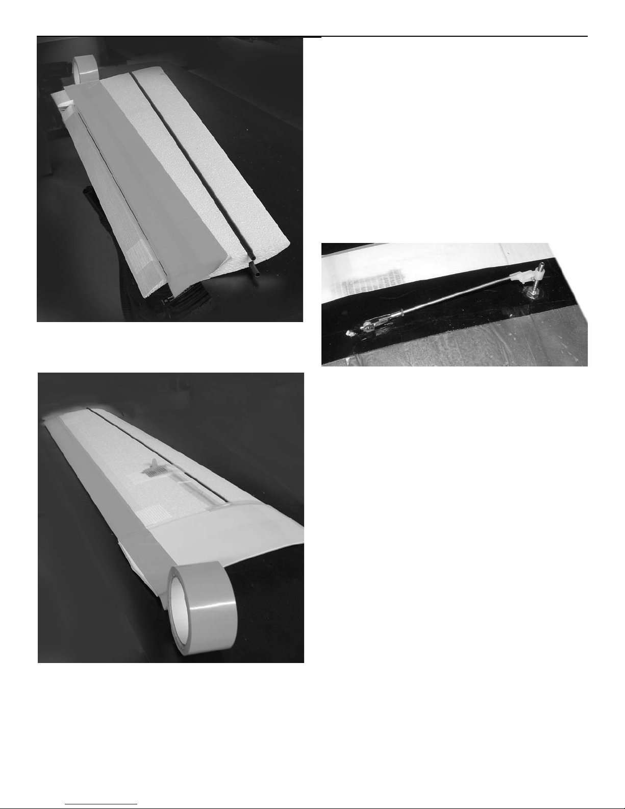
On the bottom of the wing start at
the trailing edge of the wing, not the
aileron. Flex the aileron down and
let the covering go around the trailing edge. You can then start a piece
at the leading edge of the aileron
and cover it. Continue forward with
the tape to the leading edge. Since
the tip is not as wide as the root, you
will need to over lap more at the tip.
Let the tape over lap 1/4” at the
root and adjust at the tip .
We will cover the method used with
the packing tape since it is strong
and inexpensive.
first row
Page 11
Warbird Combat
Assembly instructions
11
start the next row by overlapping
about 1/4” to 3/8” of the row you
just put down. Continue on to the
leading edge.
it is best to cover the bottom in a
contrasting color for better visibility.
If you plan to paint the tape you must
first sand it lightly with 220 grit
paper to break the glaze on the tape.
Wipe the surface down with lacquer
thinner after sanding. You can now
use one of the model paints like
Luster Coat or Rustoleum enamel
works fine. I have used krylon
Camouflage paint and it is fuel proof
and works fine.
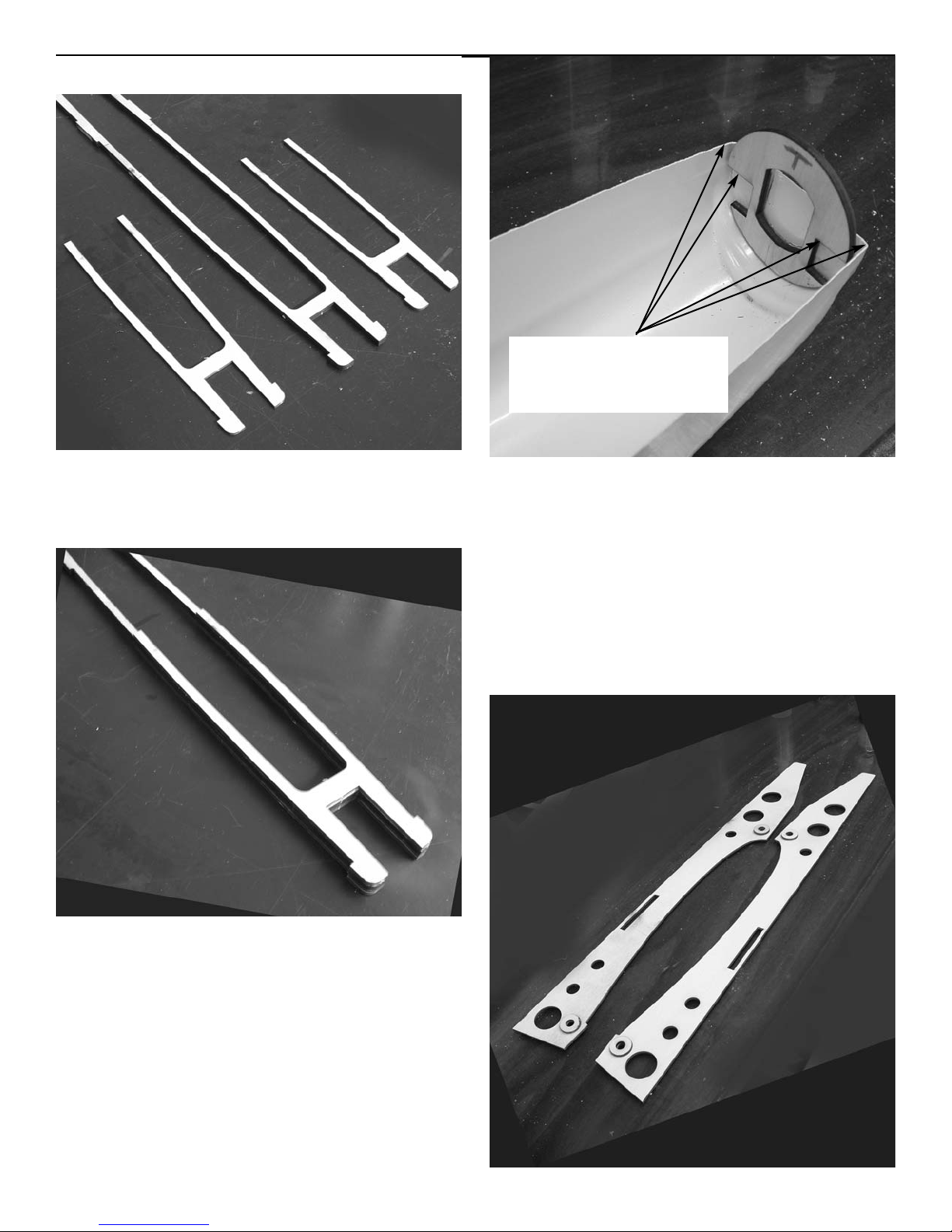
After the wing is covered, drill a
9/64” hole in the aileron in line with
the servo output arm. Drill the hole
3/8” back from the leading edge on
the top of the aileron so it will be
just at the rear of the tapered section on the bottom. Run thin CA into
the hole to harden the balsa. Install
the 6-32x1-1/2” bolt with washers
top and bottom and the nut on top.
Install the nylon pushrod end on
top. Use one of the 2-56x10”
pushrods, golden clevis and 2-56 jam
nut and attach to the servo output
arm. Center the servo and the
aileron. Mark the location of the
aileron horn and bend the pushrod
90 degrees Retain with one of the
nylon snap-r-keepers. Repeat for the
other aileron.
On the top, start at the trailing edge
of the aileron and simply pull a piece
from the tip to the center section.
Have the aileron in the full down
position. The tape is 2” wide, so let it
cover the aileron hinge line and it
will seal the gap.
Page 12
Warbird Combat
Assembly instructions
12
Fuselage construction
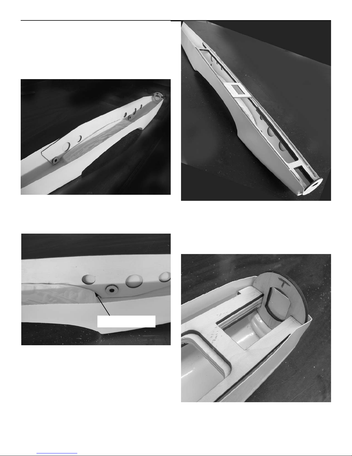
Locate the two 1/8” laser cut motor
mount doublers and the 1/4” center
fuselage support.
Laminate one of the doublers on
each side of the 1/4” piece. You can
use medium CA or epoxy.
Next locate the nose ring and the
vacuum formed fuse bottom. Glue the
nose ring in the front of the fuselage using medium CA glue. Pay attention to the side marked top and don’t
install it upside down. Make sure the
notches are aligned straight with
the fuse because this is what aligns
the center support.
notches even distance from lip of
plastic
Page 13
Warbird Combat
Assembly instructions
13
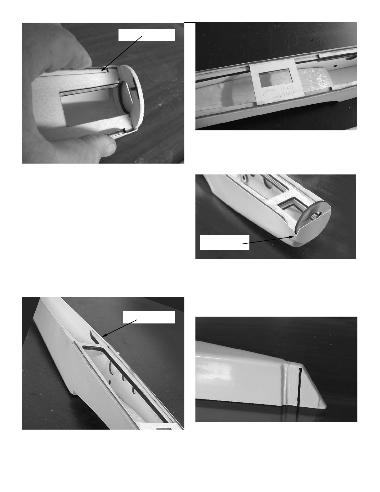
Locate the four 3/4” dowel reinforcement disc and glue them to the
inside of the fuselage crutch sides
to reinforce the wing dowel holes.
Make sure to make a left
and right side.
Place the crutch sides in the fuselage making sure they sit down in the
wing saddle.
fit here
Make sure the sides are pulled back
and fit in the front of the wing saddle.
Install the center assembly in the
fuselage with the notches on the
side fitted into the slots in the
crutch sides. Put the center in place
with the marks for the elevator
servo mount to the top side.
Fit the front of the motor mounts
into the nose ring.
Page 14
Warbird Combat
Assembly instructions
14
fit here
Pull the crutch sides in against the
motor mounts making sure they fit in
the cutout. Glue the sides to the
mounts starting at the nose. Glue
the mounts to the nose ring. Work
from the front to the back gluing
the sides to the center support.
After the sides are glued to the center support, glue the sides to the
fuselage in the wing saddle area.
Make sure the plane is sitting on a
flat surface and press the sides
down into the wing saddle so as not
to warp the fuselage.
Glue the rear portion of the center
support to the plastic behind the
fuse sides.
glue here
Glue the elevator servo mount in
place on the marks on the fuse center section.
The top half of the fuselage overlaps the bottom half 1/4” Clip the
corners of the bottom half of the
nose ring 1/4” to allow the top to fit
forming the 2” nose ring.
clip here
Mark the tail of the fuselage bottom
at the top of the angle and cut along
the line. This leaves a 3/8” flange to
mount the fin.
Page 15
Warbird Combat
Assembly instructions
15
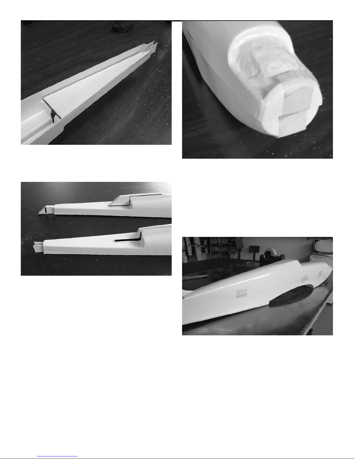
Locate the 1/8” laser cut stab
mount and glue to the inside of the
fuselage top. Use CA glue.
Trim the plastic at the rear of the
fuselage leaving flange for mounting the fin. The raised portion on the
fuselage where the fin mounts will
need to be cut. Cut just the top off
leaving a flange to mount the fin.
The portion of the plastic in the stab
saddle will need to be removed as
shown above.
Fit the top half of the fuselage over
the bottom half and hold in place
with masking tape. Start at the nose
and align the top straight over the
bottom Sight from the front and
make sure the fuse looks straight at
the cockpit area. Move the top till
the fuselage looks right.
Make sure the stab saddle is parallel to the wing saddle. Use small
pieces of masking tape to hold fuse
while you align it.
Page 16
Warbird Combat
Assembly instructions
16
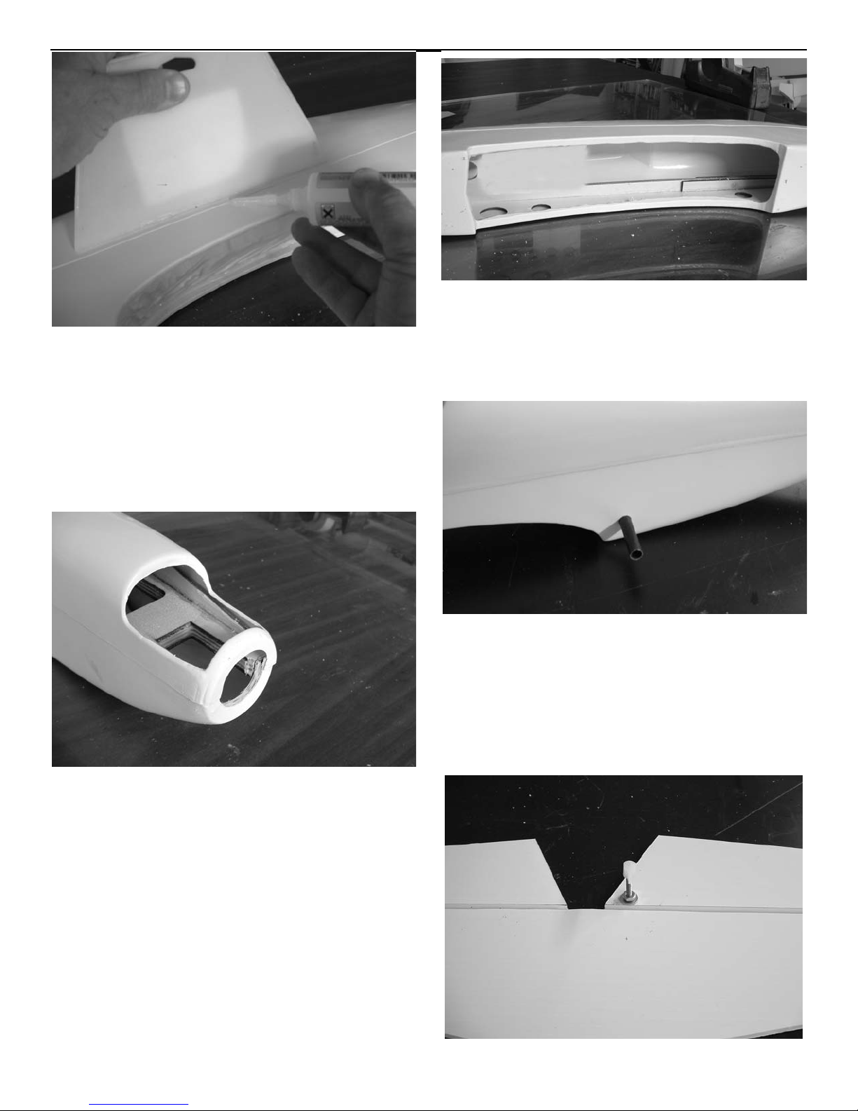
When satisfied with the fit, start
gluing in the middle of the fuse over
the wing saddle. Work from the middle to the tail then from the middle
to the nose. A large squeegee work
well to hold the seam down while
applying thin CA along the seam.
After both sides are glued down, use
an x-acto knife and cut the plastic
out of the nose ring and the engine
opening.
Cut the plastic away in the wing saddle. Cut at the bottom of the flange
which leaves a lip rolled over the
edge of the 1/8” fuselage sides.
Mark the location of the dowel
holes by reaching inside the fuse and
pushing a sharp piece of wire
through the hole in the plywood
fuselage side. Drill the plastic using
a 9/32” drill and install the epoxy
glass dowels. Glue in place with CA.
Page 17
Warbird Combat
Assembly instructions
17
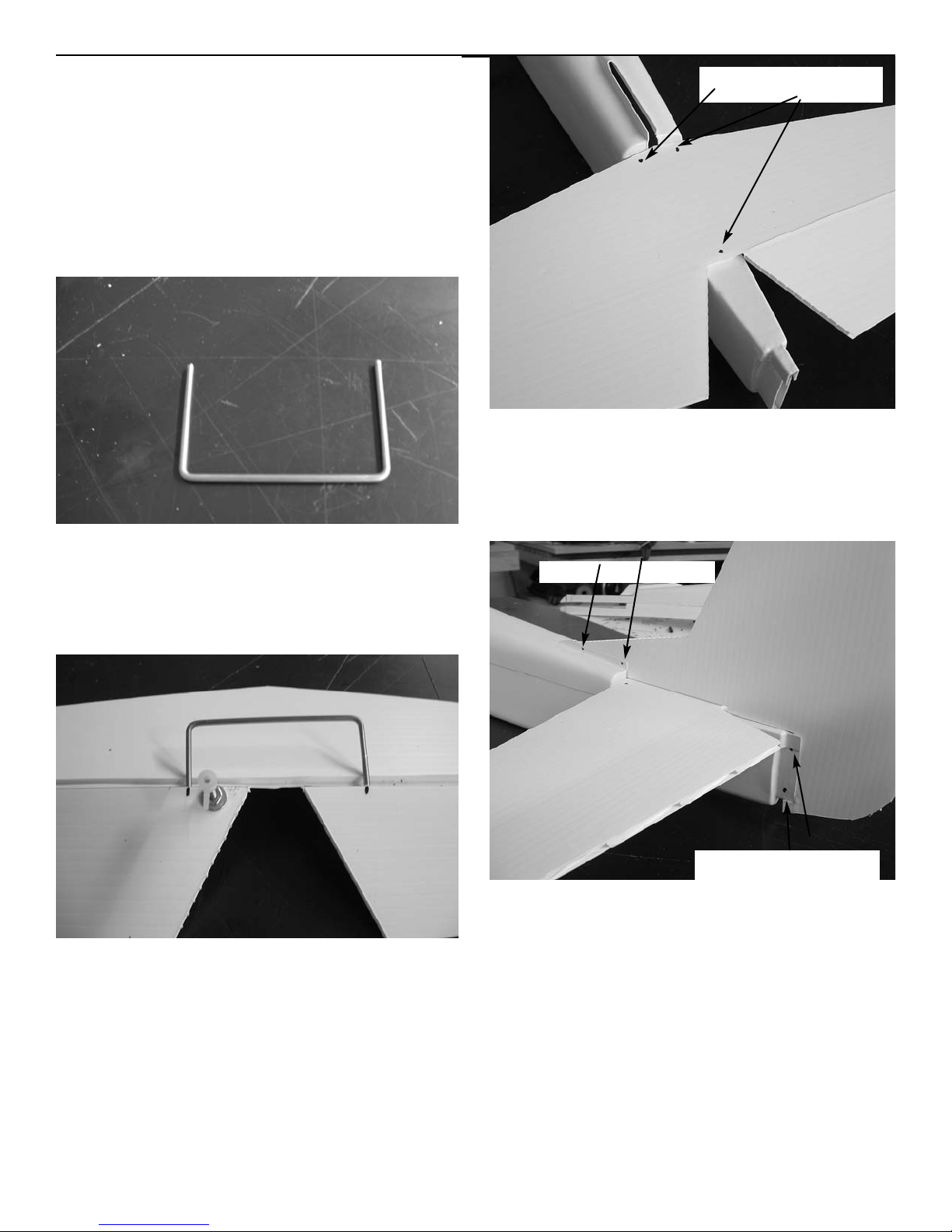
Locate the stab and mount the control horn on the bottom side. Drill a
9/16” hole 1/4” behind the hinge line
and 1/2” in on the end. Use the 6-32
x1-1/2” bolt two #6 washers and a 632 nut. Use a washer top and bottom
and glue in place with CA glue after
tightening the nut. Install the nylon
horn fitting on top.
mounting holes
Fit the stab on the fuselage and center it. Mark the hole location and
drill through the holes with a 1/16”
drill into the fuse. Mount the stab
using three #2 screws and flat washers.
mounting holes
mounting holes
Fit the fin in place and mark the
location of the mounting holes. Two
holes in the dorsal fin and two in the
rear of the fuselage. Drill a 1/16”
hole through the flange in the fuselage and the fin at the same time and
install a #2 screw. Repeat for the
other three screws.
Locate the 3/32” x 6” elevator joiner wire. Bend each end at a 90 degree
angle 1-1/4” long. Make sure it lies
flat on the table. Adjust till it does.
Mark the location of the wire on the
elevators. Use a 3/32” drill and
make a hole in each elevator half to
accept the joiner wire. Install the
wire and run some thin CA down into
the holes.
Page 18
Warbird Combat
Assembly instructions
18
Radio Installation
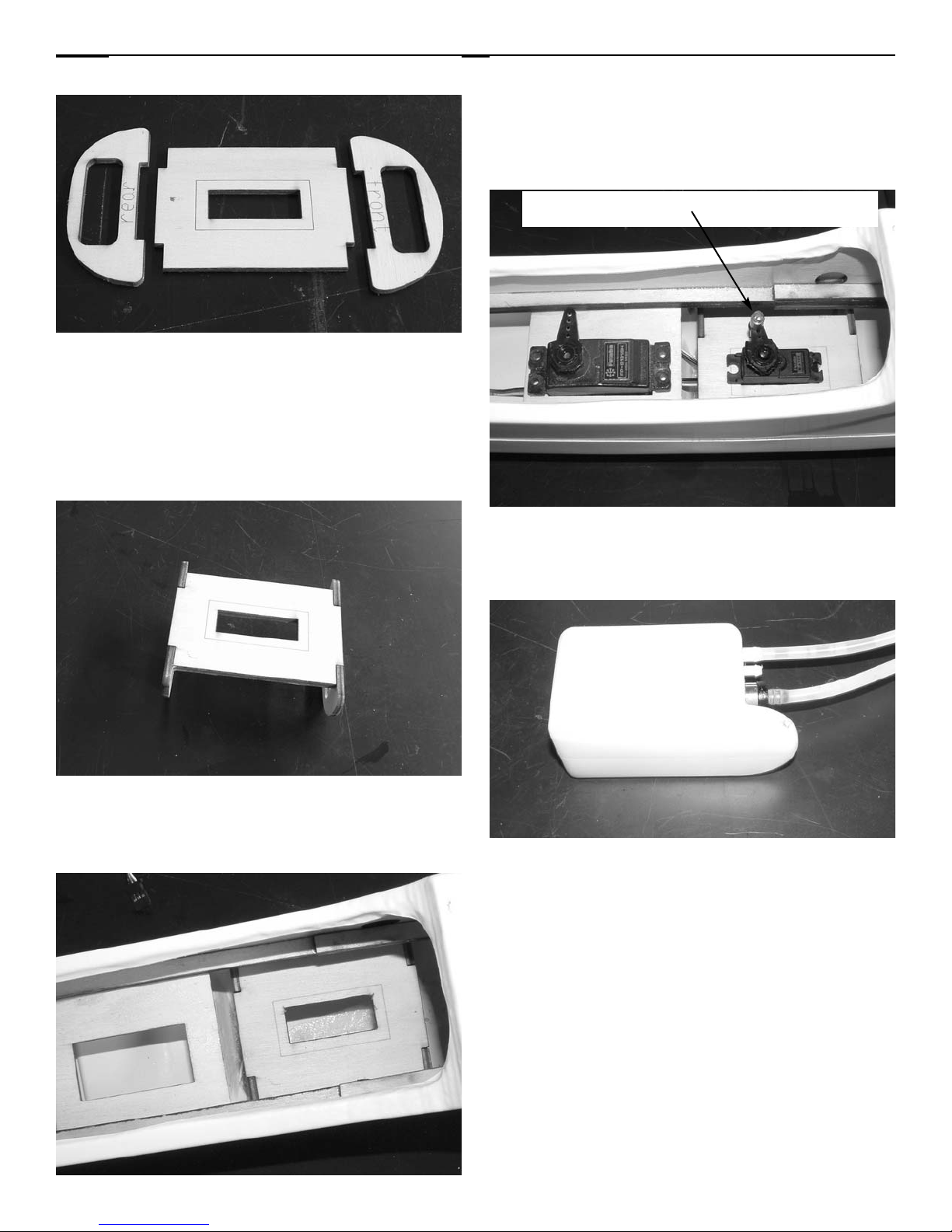
1. Locate the three pieces of the
throttle servo mount. The bulkheads
are marked front and rear. The
servo mount plate is cut out for a
mini servo and marked for a standard
servo.
2. Glue the assembly together with
the plate fitting in the notches in the
bulkhead.
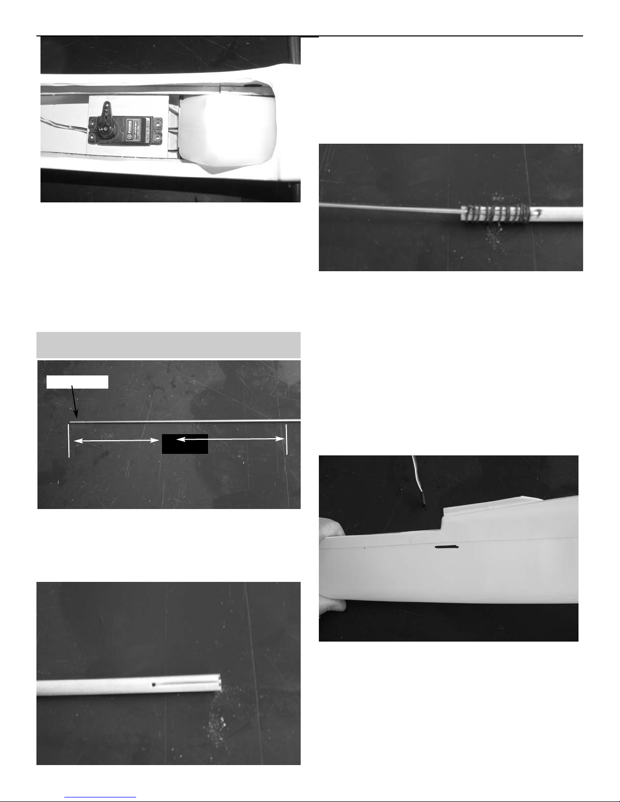
3. Slip the assembly into the fuselage
just in front of the elevator servo
mount. Make sure the bulkhead with
rear stamped on it is to the rear of
the plane. Glue in place using CA.
4. Install the elevator and throttle
servo using the hardware supplied
with the radio.
5. The Hayes, Great Planes or
Thunder Tiger 4 oz. tank will fit into
the front of the fuselage.
e-z connector on throttle arm
Page 19
Warbird Combat
Assembly instructions
19
6. The tank will slide into the fuse
over the throttle servo and fit
between the wooden rails. Push it
all the way forward and the protrusion on the bottom of the tank will
fit against the rear of the motor
mounts.
Elevator pushrod
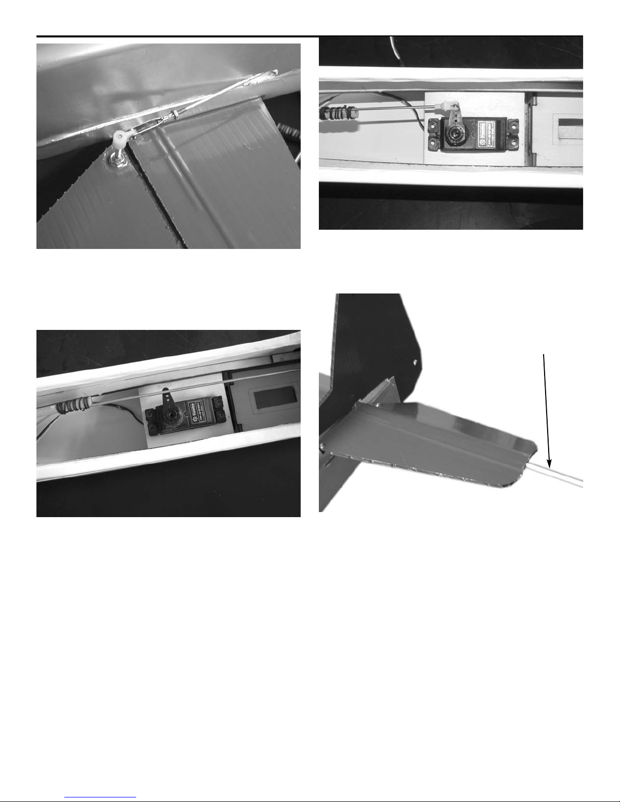
1. Locate the 2-56 x 15” pushrod and
make a 90 degree bend 7” from the
threaded end. Cut the rod off at
1/8”.
threads
7”
2. Locate the 1/4” x 11” wooden
dowel. Drill a hole(.078”) in each end
1-1/4” from each end. Use an e-xacto
knife to cut a slot from the hole to
the end of the dowel that will
accept the 2-56 wire.
3. Insert the angled end of the elevator wire into the hole in the end of
the dowel and press into the slot.
Wrap the wire with string and glue in
place with CA.
4. Take the piece of wire you cut from
the elevator pushrod wire and bend
a 90 degree angle in the end 1/8”
long. Insert it in the other end of
the dowel and wrap and glue it in
place.
5. cut a slot 3/4” long and 3/32”
wide in the rear of the fuselage on
the same side as your elevator horn
for the pushrod to exit. It should be
centered on the front edge of the
stab and just below the seam in the
fuselage.
Page 20
Warbird Combat
Assembly instructions
20
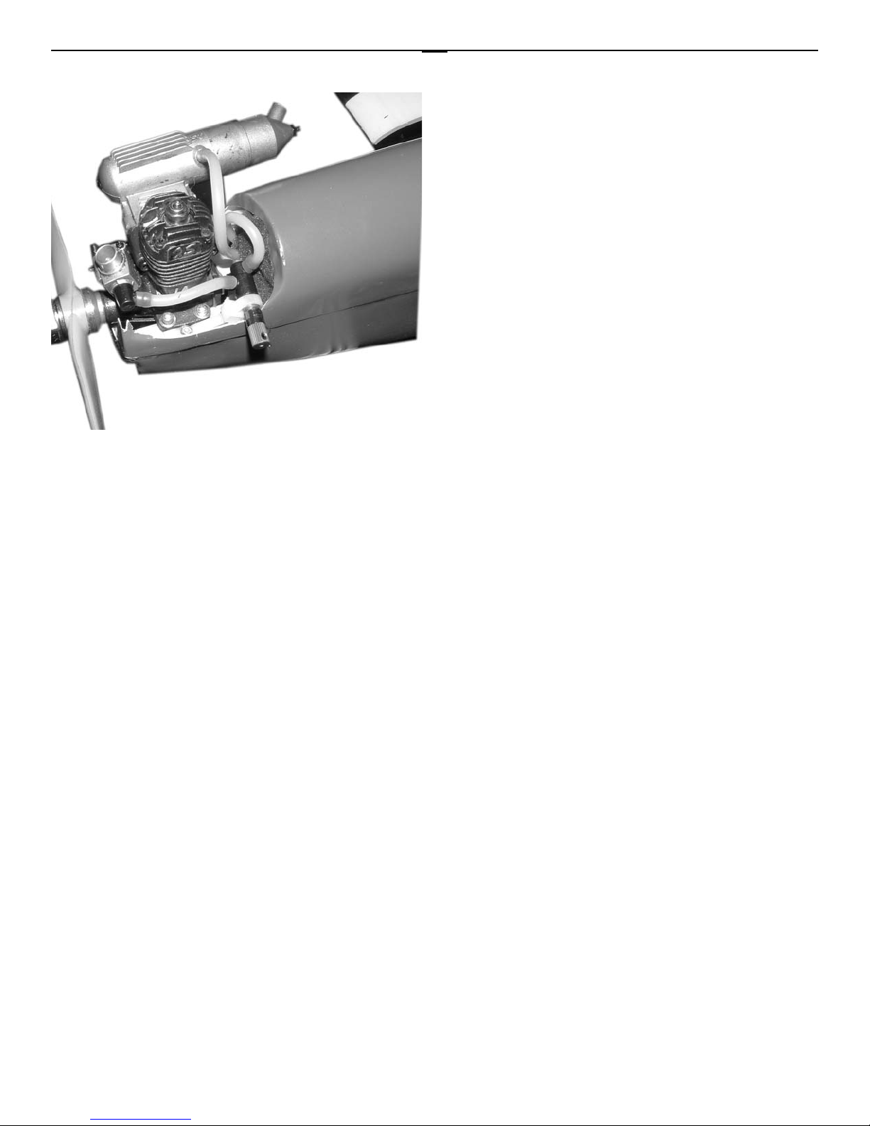
6. Fit the pushrod in the fuse and exit
the slot. Install a 2-56 nut and clevis
on the end of the rod. Hook the clevis to the elevator horn.
7. Center the elevator servo and
make sure the elevator is centered.
Mark the wire where it crosses the
elevator arm on the servo and bend
up at a 90 degree angle. Cut off at
3/8”.
8. Fit the pushrod in the arm and
retain with the nylon snap-r-keeper.
bamboo skewer
Two bamboo skewers are included to
stiffen the stab. Insert one into the
flute in the coroplast just in front
of the hinge line. Push it all the way
in, it will extend past the center of
the stab. Go to the other side and go
1 flute forward of the one on the
other side so they will not hit in the
middle. They will overlap in the center, one in front of the other. This
will add strength to the center section. The bamboo varies a lot in diameter. If too tight you may have to sand
a little then tap into place with a
hammer. If loose just apply glue and
insert and let the glue dry.
Page 21
Warbird Combat
Assembly instructions
21
Use the 15” 2-56 pushrod, golden
clevis and jam nut and attach to the
carb arm. Insert the other end
through the e-z connector on the
throttle servo and adjust linkage.
Trim the clear canopy to fit on the P51 and install using ZAP canopy
glue. The ZAP canopy glue is white
and dries clear and sticks very well
to the abs plastic or paint.
For Combat flying I don’t use a
switch, one more item to break. You
can use a dremel tool and cut a 1/2”
long slot 1/8” wide in the side of the
fuselage just above the forward
wing hold down dowel. The battery
lead and power lead from the receiver can be routed out this slot and
plugged in when ready to fly. If you
wish you can install a switch in the
fuse side.
The CG should be on the main spars
at the side of the fuselage. Mark the
location on the top of the wing next
to the fuselage and invert the plane.
If you don’t have a balance stand,
place one finger on the marks on
each side and the plane should sit
level or slightly nose down. Add
weight if necessary to make it balance.
The control throws should be 1/2”
up and down on the elevator on low
rate and 3/4” on high rate. The
ailerons should be 3/8” low rate
and 5/8” high rate. The elevator
throw should be adjusted so that a
full up elevator loop does not cause
the plane to snap out. If the plane is
snapping out in loops or tight turns,
reduce the elevator throw.
Install the engine between the
beams and twist the motor to the
right. This will give a small amount
of right thrust which is all you
need(1 degree).The top part of the
nose ring will probably have to be
removed to not interfere with the
carb. Mark the location of the
mounting holes and drill the mounts.
Install 4-40 blind nuts and mount the
engine using 4-40x 1” bolts (bolts and
nuts not included).
Motor Installation
Page 22
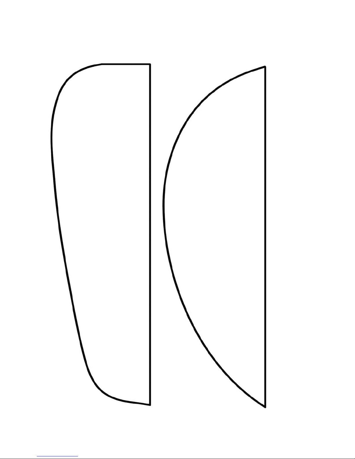
BF109 tip
P-51 tip
 Loading...