

Page 1

User’s Guide
© 2005 Ricoh Printing Systems, Ltd.
N905363
Page 2

© 2005 Ricoh Printing Systems, Ltd. All rights reserved.
No part of this document may be reproduced without the express permission of Ricoh
Printing Systems, Ltd.
The material in this document is for informational purposes and is subject to change
without notice. Ricoh Printing Systems, Ltd. assumes no responsibility for errors or
omissions in this doc ument. No l iabi lit y is ass umed for a ny damage s resul ting f rom the
use of the information it contains.
NOTICE TO USER
In an effort to meet t he demands of a ra pidly changing t echn ology, the manufac turer is
continually developing new features and functions to meet your changing printing or
printer needs. As a result, this manual may not exact ly reflect future changes made to
the product. Please be sure to consult all manual updates or addenda when using this
product’s documentation.
Page 3

Rev. Table
Rev. for
Manual
Machine
Rev.
Page No. (Contents) Date
00 - First Edition Jul. 21, 2005
Page 4

Blank
Page 5

Table of Contents
SAFETY SUMMARY. . . . . . . . . . . . . . . . . . . . . . . . . . . . . . . . . . . . . .Safety Summary-1
SICHERHEIT ZUSAMMENFASSUNG . . . . . . . Siche rheit Zu sammenf assung-1
Introduction
About This Manual . . . . . . . . . . . . . . . . . . . . . . . . . . . . . . . . . . . . . . . . . . . . . . . . . . . . . . . . . . 0-1
Audience . . . . . . . . . . . . . . . . . . . . . . . . . . . . . . . . . . . . . . . . . . . . . . . . . . . . . . . . . . . . . . 0-1
Manual Conventions . . . . . . . . . . . . . . . . . . . . . . . . . . . . . . . . . . . . . . . . . . . . . . . . . . . . . 0-2
For More Information . . . . . . . . . . . . . . . . . . . . . . . . . . . . . . . . . . . . . . . . . . . . . . . . . . . . 0-2
Chapter 1. Printer Overview
What This Chapter Provides. . . . . . . . . . . . . . . . . . . . . . . . . . . . . . . . . . . . . . . . . . . . . . . . . . . 1-1
Printer Features . . . . . . . . . . . . . . . . . . . . . . . . . . . . . . . . . . . . . . . . . . . . . . . . . . . . . . . . . . . . . 1-2
I/O Configurations . . . . . . . . . . . . . . . . . . . . . . . . . . . . . . . . . . . . . . . . . . . . . . . . . . . . . . . 1-3
Operator Control Panel . . . . . . . . . . . . . . . . . . . . . . . . . . . . . . . . . . . . . . . . . . . . . . . . . . . 1-3
External View of the Printer . . . . . . . . . . . . . . . . . . . . . . . . . . . . . . . . . . . . . . . . . . . . . . . . . . . 1-4
Internal View of the Printer. . . . . . . . . . . . . . . . . . . . . . . . . . . . . . . . . . . . . . . . . . . . . . . . . . . . 1-5
Powering On the Printer . . . . . . . . . . . . . . . . . . . . . . . . . . . . . . . . . . . . . . . . . . . . . . . . . . . . . . 1-6
Powering Off the Printer. . . . . . . . . . . . . . . . . . . . . . . . . . . . . . . . . . . . . . . . . . . . . . . . . . . . . . 1-7
Clearing Error Condition s . . . . . . . . . . . . . . . . . . . . . . . . . . . . . . . . . . . . . . . . . . . . . . . . . 1-8
Space Required for Installation. . . . . . . . . . . . . . . . . . . . . . . . . . . . . . . . . . . . . . . . . . . . . . . . 1-10
Chapter 2. Control Panels
What This Chapter Provides. . . . . . . . . . . . . . . . . . . . . . . . . . . . . . . . . . . . . . . . . . . . . . . . . . . 2-1
Description of Control Panels. . . . . . . . . . . . . . . . . . . . . . . . . . . . . . . . . . . . . . . . . . . . . . . . . . 2-2
OCP Menu Icons and Buttons. . . . . . . . . . . . . . . . . . . . . . . . . . . . . . . . . . . . . . . . . . . . . . . . . . 2-3
Using the OCP Menus. . . . . . . . . . . . . . . . . . . . . . . . . . . . . . . . . . . . . . . . . . . . . . . . . . . . . . . . 2-4
Using the Option Button Menu . . . . . . . . . . . . . . . . . . . . . . . . . . . . . . . . . . . . . . . . . . . . . 2-4
Using the Ten Key Pad Menu. . . . . . . . . . . . . . . . . . . . . . . . . . . . . . . . . . . . . . . . . . . . . . . 2-5
Using the + / - C hange Button Menu . . . . . . . . . . . . . . . . . . . . . . . . . . . . . . . . . . . . . . . . . 2-6
Using the Enable/Disab le Change Button Menu . . . . . . . . . . . . . . . . . . . . . . . . . . . . . . . . 2-7
OCP Menu Structure. . . . . . . . . . . . . . . . . . . . . . . . . . . . . . . . . . . . . . . . . . . . . . . . . . . . . . . . . 2-8
Main Menu . . . . . . . . . . . . . . . . . . . . . . . . . . . . . . . . . . . . . . . . . . . . . . . . . . . . . . . . . . . . . 2-8
Information Menu. . . . . . . . . . . . . . . . . . . . . . . . . . . . . . . . . . . . . . . . . . . . . . . . . . . . . . . . 2-9
Printer Menu. . . . . . . . . . . . . . . . . . . . . . . . . . . . . . . . . . . . . . . . . . . . . . . . . . . . . . . . . . . 2-11
Setup Menu. . . . . . . . . . . . . . . . . . . . . . . . . . . . . . . . . . . . . . . . . . . . . . . . . . . . . . . . . . . . 2-18
Reports Menu . . . . . . . . . . . . . . . . . . . . . . . . . . . . . . . . . . . . . . . . . . . . . . . . . . . . . . . . . . 2-22
Jobs Menu. . . . . . . . . . . . . . . . . . . . . . . . . . . . . . . . . . . . . . . . . . . . . . . . . . . . . . . . . . . . . 2-23
Sub Panel. . . . . . . . . . . . . . . . . . . . . . . . . . . . . . . . . . . . . . . . . . . . . . . . . . . . . . . . . . . . . . . . . 2-24
Table of Contents v
OG L
0 0
Page 6

Chapter 3. Paper Handling
What This Chapter Provides. . . . . . . . . . . . . . . . . . . . . . . . . . . . . . . . . . . . . . . . . . . . . . . . . . . 3-1
Paper . . . . . . . . . . . . . . . . . . . . . . . . . . . . . . . . . . . . . . . . . . . . . . . . . . . . . . . . . . . . . . . . . . . . . 3-2
Unacceptable Paper . . . . . . . . . . . . . . . . . . . . . . . . . . . . . . . . . . . . . . . . . . . . . . . . . . . . . . 3-2
Storing Paper . . . . . . . . . . . . . . . . . . . . . . . . . . . . . . . . . . . . . . . . . . . . . . . . . . . . . . . . . . . 3-2
Paper Sizes, Paper Weights, Paper Types and Paper Color . . . . . . . . . . . . . . . . . . . . . . . . . . . 3-3
Paper Size . . . . . . . . . . . . . . . . . . . . . . . . . . . . . . . . . . . . . . . . . . . . . . . . . . . . . . . . . . . . . . 3-3
Paper Size Indication . . . . . . . . . . . . . . . . . . . . . . . . . . . . . . . . . . . . . . . . . . . . . . . . . . . . . 3-4
Paper Weights. . . . . . . . . . . . . . . . . . . . . . . . . . . . . . . . . . . . . . . . . . . . . . . . . . . . . . . . . . . 3-5
Paper Type . . . . . . . . . . . . . . . . . . . . . . . . . . . . . . . . . . . . . . . . . . . . . . . . . . . . . . . . . . . . . 3-5
Loading Paper . . . . . . . . . . . . . . . . . . . . . . . . . . . . . . . . . . . . . . . . . . . . . . . . . . . . . . . . . . . . . . 3-7
Proper Paper Handling . . . . . . . . . . . . . . . . . . . . . . . . . . . . . . . . . . . . . . . . . . . . . . . . . . . . 3-7
Loading Paper in Tray . . . . . . . . . . . . . . . . . . . . . . . . . . . . . . . . . . . . . . . . . . . . . . . . . . . . 3-9
Loading Special Media. . . . . . . . . . . . . . . . . . . . . . . . . . . . . . . . . . . . . . . . . . . . . . . . . . . . 3-6
Setting the Non-Standard Paper Size . . . . . . . . . . . . . . . . . . . . . . . . . . . . . . . . . . . . . . . . . . . 3-15
Setting the Paper Weight Value . . . . . . . . . . . . . . . . . . . . . . . . . . . . . . . . . . . . . . . . . . . . . . . 3-19
Setting the HV Adjust Values. . . . . . . . . . . . . . . . . . . . . . . . . . . . . . . . . . . . . . . . . . . . . . . . . 3-21
Setting the Table Adjust . . . . . . . . . . . . . . . . . . . . . . . . . . . . . . . . . . . . . . . . . . . . . . . . . . . . . 3-23
Setting the Paper Moisture . . . . . . . . . . . . . . . . . . . . . . . . . . . . . . . . . . . . . . . . . . . . . . . . . . . 3-25
Preparing the Stacker . . . . . . . . . . . . . . . . . . . . . . . . . . . . . . . . . . . . . . . . . . . . . . . . . . . . . . . 3-27
Set the Basket into the Stacker. . . . . . . . . . . . . . . . . . . . . . . . . . . . . . . . . . . . . . . . . . . . . 3-27
Removing Paper . . . . . . . . . . . . . . . . . . . . . . . . . . . . . . . . . . . . . . . . . . . . . . . . . . . . . . . . . . . 3-28
Removing Paper from the Stacker . . . . . . . . . . . . . . . . . . . . . . . . . . . . . . . . . . . . . . . . . . 3-28
Chapter 4. Care and Maintenance
What This Chapter Provides. . . . . . . . . . . . . . . . . . . . . . . . . . . . . . . . . . . . . . . . . . . . . . . . . . . 4-1
Replacing Consumables . . . . . . . . . . . . . . . . . . . . . . . . . . . . . . . . . . . . . . . . . . . . . . . . . . . . . . 4-2
Adding Toner . . . . . . . . . . . . . . . . . . . . . . . . . . . . . . . . . . . . . . . . . . . . . . . . . . . . . . . . . . . 4-2
Replacing the Toner Bag . . . . . . . . . . . . . . . . . . . . . . . . . . . . . . . . . . . . . . . . . . . . . . . . . . 4-7
Replacing the Developer Mix . . . . . . . . . . . . . . . . . . . . . . . . . . . . . . . . . . . . . . . . . . . . . . 4-9
Replacing the Fuser Cleaning Web . . . . . . . . . . . . . . . . . . . . . . . . . . . . . . . . . . . . . . . . . 4-17
Replacing the Fine Filter . . . . . . . . . . . . . . . . . . . . . . . . . . . . . . . . . . . . . . . . . . . . . . . . . 4-20
Winding the OPC Sheet . . . . . . . . . . . . . . . . . . . . . . . . . . . . . . . . . . . . . . . . . . . . . . . . . . 4-22
Clearing Paper Jams . . . . . . . . . . . . . . . . . . . . . . . . . . . . . . . . . . . . . . . . . . . . . . . . . . . . . . . . 4-24
Regist Cover . . . . . . . . . . . . . . . . . . . . . . . . . . . . . . . . . . . . . . . . . . . . . . . . . . . . . . . . . . 4-25
Input Station Area. . . . . . . . . . . . . . . . . . . . . . . . . . . . . . . . . . . . . . . . . . . . . . . . . . . . . . . 4-27
Regist Station Area . . . . . . . . . . . . . . . . . . . . . . . . . . . . . . . . . . . . . . . . . . . . . . . . . . . . . 4-29
Paper Feed Area . . . . . . . . . . . . . . . . . . . . . . . . . . . . . . . . . . . . . . . . . . . . . . . . . . . . . . . . 4-31
Container Stacker . . . . . . . . . . . . . . . . . . . . . . . . . . . . . . . . . . . . . . . . . . . . . . . . . . . . . . 4-41
High Capacity Feeder (HCF) . . . . . . . . . . . . . . . . . . . . . . . . . . . . . . . . . . . . . . . . . . . . . . 4-48
Cleaning the Printer. . . . . . . . . . . . . . . . . . . . . . . . . . . . . . . . . . . . . . . . . . . . . . . . . . . . . . . . . 4-51
Cleaning the Printer Covers . . . . . . . . . . . . . . . . . . . . . . . . . . . . . . . . . . . . . . . . . . . . . . . 4-52
Cleaning Trays . . . . . . . . . . . . . . . . . . . . . . . . . . . . . . . . . . . . . . . . . . . . . . . . . . . . . . . . . 4-52
Cleaning the Container Baskets . . . . . . . . . . . . . . . . . . . . . . . . . . . . . . . . . . . . . . . . . . . . 4-53
Cleaning the Toner Bottle Joint . . . . . . . . . . . . . . . . . . . . . . . . . . . . . . . . . . . . . . . . . . . . 4-54
Cleaning the Discharger and the Detach Corotoron. . . . . . . . . . . . . . . . . . . . . . . . . . . . . 4-55
vi Table of Contents
OG L
0 0
Page 7

Clearing the Inverter Valve Peace . . . . . . . . . . . . . . . . . . . . . . . . . . . . . . . . . . . . . . . . . . 4-56
Handling and Storing Supplies and Consumables . . . . . . . . . . . . . . . . . . . . . . . . . . . . . . . . . 4-58
Paper . . . . . . . . . . . . . . . . . . . . . . . . . . . . . . . . . . . . . . . . . . . . . . . . . . . . . . . . . . . . . . . . 4-58
Toner and Developer . . . . . . . . . . . . . . . . . . . . . . . . . . . . . . . . . . . . . . . . . . . . . . . . . . . . 4-59
Chapter 5. Troubleshooting
What This Chapter Provides. . . . . . . . . . . . . . . . . . . . . . . . . . . . . . . . . . . . . . . . . . . . . . . . . . . 5-1
Guidelines Flowchart . . . . . . . . . . . . . . . . . . . . . . . . . . . . . . . . . . . . . . . . . . . . . . . . . . . . . . . . 5-2
Basic Troubleshooting Tips . . . . . . . . . . . . . . . . . . . . . . . . . . . . . . . . . . . . . . . . . . . . . . . . . . . 5-3
General Printing Problems . . . . . . . . . . . . . . . . . . . . . . . . . . . . . . . . . . . . . . . . . . . . . . . . . . . . 5-4
Print Quality Problems . . . . . . . . . . . . . . . . . . . . . . . . . . . . . . . . . . . . . . . . . . . . . . . . . . . . . . . 5-6
Duplex Printing Problems. . . . . . . . . . . . . . . . . . . . . . . . . . . . . . . . . . . . . . . . . . . . . . . . . . . . . 5-6
Printer Notice . . . . . . . . . . . . . . . . . . . . . . . . . . . . . . . . . . . . . . . . . . . . . . . . . . . . . . . . . . . . . . 5-7
OCP Display Messages. . . . . . . . . . . . . . . . . . . . . . . . . . . . . . . . . . . . . . . . . . . . . . . . . . . . . . . 5-8
Printer Status Message . . . . . . . . . . . . . . . . . . . . . . . . . . . . . . . . . . . . . . . . . . . . . . . . . . . . 5-8
Printer Warning Message . . . . . . . . . . . . . . . . . . . . . . . . . . . . . . . . . . . . . . . . . . . . . . . . . 5-10
Printer Error Message. . . . . . . . . . . . . . . . . . . . . . . . . . . . . . . . . . . . . . . . . . . . . . . . . . . . 5-10
Chapter 6. Web Utilities
What This Chapter Provides. . . . . . . . . . . . . . . . . . . . . . . . . . . . . . . . . . . . . . . . . . . . . . . . . . . 6-1
Overview. . . . . . . . . . . . . . . . . . . . . . . . . . . . . . . . . . . . . . . . . . . . . . . . . . . . . . . . . . . . . . . . . . 6-1
Access and Security . . . . . . . . . . . . . . . . . . . . . . . . . . . . . . . . . . . . . . . . . . . . . . . . . . . . . . 6-3
Accessing the Web Utilities . . . . . . . . . . . . . . . . . . . . . . . . . . . . . . . . . . . . . . . . . . . . . . . . 6-4
Web Page Organization . . . . . . . . . . . . . . . . . . . . . . . . . . . . . . . . . . . . . . . . . . . . . . . . . . . 6-5
Manage Status Options . . . . . . . . . . . . . . . . . . . . . . . . . . . . . . . . . . . . . . . . . . . . . . . . . . . . . . . 6-8
Status-General . . . . . . . . . . . . . . . . . . . . . . . . . . . . . . . . . . . . . . . . . . . . . . . . . . . . . . . . . . 6-9
Status-Tray . . . . . . . . . . . . . . . . . . . . . . . . . . . . . . . . . . . . . . . . . . . . . . . . . . . . . . . . . . . . 6-10
Status-Paper Output . . . . . . . . . . . . . . . . . . . . . . . . . . . . . . . . . . . . . . . . . . . . . . . . . . . . . 6-11
Status-Consumables . . . . . . . . . . . . . . . . . . . . . . . . . . . . . . . . . . . . . . . . . . . . . . . . . . . . . 6-12
Status-Errors. . . . . . . . . . . . . . . . . . . . . . . . . . . . . . . . . . . . . . . . . . . . . . . . . . . . . . . . . . . 6-13
Status-Usage . . . . . . . . . . . . . . . . . . . . . . . . . . . . . . . . . . . . . . . . . . . . . . . . . . . . . . . . . . . 6-14
Status-Network . . . . . . . . . . . . . . . . . . . . . . . . . . . . . . . . . . . . . . . . . . . . . . . . . . . . . . . . . 6-15
Status-Report . . . . . . . . . . . . . . . . . . . . . . . . . . . . . . . . . . . . . . . . . . . . . . . . . . . . . . . . . . 6-16
Status-Revision. . . . . . . . . . . . . . . . . . . . . . . . . . . . . . . . . . . . . . . . . . . . . . . . . . . . . . . . . 6-17
Manage System Options . . . . . . . . . . . . . . . . . . . . . . . . . . . . . . . . . . . . . . . . . . . . . . . . . . . . . 6-18
System-General . . . . . . . . . . . . . . . . . . . . . . . . . . . . . . . . . . . . . . . . . . . . . . . . . . . . . . . . 6-19
System-Tray . . . . . . . . . . . . . . . . . . . . . . . . . . . . . . . . . . . . . . . . . . . . . . . . . . . . . . . . . . . 6-21
System-Paper Output . . . . . . . . . . . . . . . . . . . . . . . . . . . . . . . . . . . . . . . . . . . . . . . . . . . . 6-25
System-Virtual Printer . . . . . . . . . . . . . . . . . . . . . . . . . . . . . . . . . . . . . . . . . . . . . . . . . . . 6-26
System-Accounting . . . . . . . . . . . . . . . . . . . . . . . . . . . . . . . . . . . . . . . . . . . . . . . . . . . . . 6-33
System-Jobs . . . . . . . . . . . . . . . . . . . . . . . . . . . . . . . . . . . . . . . . . . . . . . . . . . . . . . . . . . . 6-34
System-Serial Number . . . . . . . . . . . . . . . . . . . . . . . . . . . . . . . . . . . . . . . . . . . . . . . . . . . 6-35
Manage Configuration Options. . . . . . . . . . . . . . . . . . . . . . . . . . . . . . . . . . . . . . . . . . . . . . . . 6-36
Configuration-General . . . . . . . . . . . . . . . . . . . . . . . . . . . . . . . . . . . . . . . . . . . . . . . . . . . 6-37
Configuration-Events . . . . . . . . . . . . . . . . . . . . . . . . . . . . . . . . . . . . . . . . . . . . . . . . . . . . 6-38
Configuration-Configuration . . . . . . . . . . . . . . . . . . . . . . . . . . . . . . . . . . . . . . . . . . . . . . 6-39
OG L
Table of Contents vii
0 0
Page 8

Configuration-Communication. . . . . . . . . . . . . . . . . . . . . . . . . . . . . . . . . . . . . . . . . . . . . 6-43
Using the Accounting File . . . . . . . . . . . . . . . . . . . . . . . . . . . . . . . . . . . . . . . . . . . . . . . . . . . 6-47
Appendix A . Specifications
What This Appendix Contains . . . . . . . . . . . . . . . . . . . . . . . . . . . . . . . . . . . . . . . . . . . . . . . . .A-1
Specifications . . . . . . . . . . . . . . . . . . . . . . . . . . . . . . . . . . . . . . . . . . . . . . . . . . . . . . . . . . . . . .A-2
Base Printer. . . . . . . . . . . . . . . . . . . . . . . . . . . . . . . . . . . . . . . . . . . . . . . . . . . . . . . . . . . . .A-2
Consumables. . . . . . . . . . . . . . . . . . . . . . . . . . . . . . . . . . . . . . . . . . . . . . . . . . . . . . . . . . . .A-3
Append ix B. Pa per S pecifications
Media Guidelines . . . . . . . . . . . . . . . . . . . . . . . . . . . . . . . . . . . . . . . . . . . . . . . . . . . . . . . . . . .B-1
General Media Recommendations . . . . . . . . . . . . . . . . . . . . . . . . . . . . . . . . . . . . . . . . . . .B-1
Paper Specifications . . . . . . . . . . . . . . . . . . . . . . . . . . . . . . . . . . . . . . . . . . . . . . . . . . . . .B-2
Paper Weight . . . . . . . . . . . . . . . . . . . . . . . . . . . . . . . . . . . . . . . . . . . . . . . . . . . . . . . . . . .B-3
Paper Color . . . . . . . . . . . . . . . . . . . . . . . . . . . . . . . . . . . . . . . . . . . . . . . . . . . . . . . . . . . .B-3
Paper Composition . . . . . . . . . . . . . . . . . . . . . . . . . . . . . . . . . . . . . . . . . . . . . . . . . . . . . .B-4
Paper Cut . . . . . . . . . . . . . . . . . . . . . . . . . . . . . . . . . . . . . . . . . . . . . . . . . . . . . . . . . . . . . .B-4
Paper Smoothness . . . . . . . . . . . . . . . . . . . . . . . . . . . . . . . . . . . . . . . . . . . . . . . . . . . . . . .B-4
Paper Fusing . . . . . . . . . . . . . . . . . . . . . . . . . . . . . . . . . . . . . . . . . . . . . . . . . . . . . . . . . . .B-4
Moisture . . . . . . . . . . . . . . . . . . . . . . . . . . . . . . . . . . . . . . . . . . . . . . . . . . . . . . . . . . . . . . .B-5
Paper Curl . . . . . . . . . . . . . . . . . . . . . . . . . . . . . . . . . . . . . . . . . . . . . . . . . . . . . . . . . . . . .B-6
Recycled Paper . . . . . . . . . . . . . . . . . . . . . . . . . . . . . . . . . . . . . . . . . . . . . . . . . . . . . . . . .B-7
Grain Direction . . . . . . . . . . . . . . . . . . . . . . . . . . . . . . . . . . . . . . . . . . . . . . . . . . . . . . . . .B-7
Paper Smoothness . . . . . . . . . . . . . . . . . . . . . . . . . . . . . . . . . . . . . . . . . . . . . . . . . . . . . . .B-7
Special Media . . . . . . . . . . . . . . . . . . . . . . . . . . . . . . . . . . . . . . . . . . . . . . . . . . . . . . . . . . . . . .B-8
Preprinted Paper . . . . . . . . . . . . . . . . . . . . . . . . . . . . . . . . . . . . . . . . . . . . . . . . . . . . . . . .B-8
Prepunched Paper . . . . . . . . . . . . . . . . . . . . . . . . . . . . . . . . . . . . . . . . . . . . . . . . . . . . . .B-10
Adhesive Labels . . . . . . . . . . . . . . . . . . . . . . . . . . . . . . . . . . . . . . . . . . . . . . . . . . . . . . . B-12
Perforated Paper . . . . . . . . . . . . . . . . . . . . . . . . . . . . . . . . . . . . . . . . . . . . . . . . . . . . . . . B-15
Printing Guidelines . . . . . . . . . . . . . . . . . . . . . . . . . . . . . . . . . . . . . . . . . . . . . . . . . . . . . . . . .B-17
Printable Area . . . . . . . . . . . . . . . . . . . . . . . . . . . . . . . . . . . . . . . . . . . . . . . . . . . . . . . . .B-17
Preprinted Lines . . . . . . . . . . . . . . . . . . . . . . . . . . . . . . . . . . . . . . . . . . . . . . . . . . . . . . . .B-18
Preprint Inhibited Area. . . . . . . . . . . . . . . . . . . . . . . . . . . . . . . . . . . . . . . . . . . . . . . . . . .B-18
Glossary
viii Table of Contents
OG L
0 0
Page 9
SAFETY SUMMARY
General Safety Guidelines
Before operating the machi ne, read the following instructions carefully:
■ Allow all the operating procedures provided in this manual.
■ Pay special attention to and follow all the hazard warning on the machine and in
the manual. Failure to do so can cause injury to yourself or damage to the
machine.
■ The hazard warnings which appear on the warning labels on the machine or in the
manual have one of the following alert headings consisting of an alert symbol and
a signal ward, DANGER, WARNING, or CAUTION.
DANGER! : indicates an imminently hazardous situation which, if not avoided,
will result in death or serious injury.
WARNING!: indicates a potentially hazardous situation which, if not avoided,
can result in death or serious injury.
CAUTION!: indicates a hazardous situation which, if not avoided, will or can
result in minor or moderate injury, or serious damage of product.
The alert symbol shown left precedes every signal word for hazard
warnings, and appears in safety related descriptions in the man ual.
The signal word ’NOTE’ is used to present warn ings which are not directly related to
personal injury hazards.
■ Do not perform any operation or action in any way other than as provided in this
manual. When in doubt, call the d esignated field engineer.
■ Keep in mind that the hazard warn ings in this manual or on the machine cannot
cover every possible case, as it is impossible to predict and evaluate all
circumstances beforehand. Be alert and use your common sense.
OG L
Safety Summary -1
0 0
Page 10

SAFETY SUMMARY
Hazard Warming Statements
WARNING Statement
■ “Use of controls, adj ustments or performance of procedures othe r than those
specified in this manual may result in hazardous laser radiation exposure.” on
page Safet y Summa r y-5
■ “Connect the power plug only to a properly rated power outlet. Otherwise, a fire
or shock hazard may result.” on pa ge Safety Summary-7
■ “Never use multi-plug adaptors to plug multiple power plugs into the same power
source. Be sure to operate the printer on a sole-use receptacle. Multiple
connectors can cause overheating and a fire could result.” on page Safety
Summary-7
■ “The pri nter must be connected to the grounding power outlet for safe and proper
operation.” on page Safety Summary-7
■ “Apparatet må kun tilkoples jordet stikkontakt.” on page Safety Summary-7
■ “Apparaten skall ansulatas till jordat uttag när den ansluts till ett nätverk.” on
page Safet y Summa r y-7
■ “Für einen sicheren und ordnungsgemäßen Betrieb muß der Drucker an eine
geerdete Steckdose angeschlossen werden.” on pa ge Safety Summary-7
■ “These statements indicate a need for special care and safety to prevent you from
harming yourself when carrying, unpacking, assembling, installing, or operating
the product.” on page 1-2
■ “To avoid serious injury or death, disconnect the power cord from the power
outlet. Do not attempt to perform any servicing operation when the power cord is
connected to the power outlet. The AC line voltage is present inside the controller
enclosure regardless of the main power switch position.” on page 1-3
■ “Do not throw the toner bottle into a fire because it may suddenly burn, causing a
risk of fire or personal injury.” on page 4-6
■ “Dispose the toner bottle as incombustible waste.” on page 4 -6
■ “Waste materials should be disposed of or incinerated under conditions which
meet all federal, state and local environmental regulations. Since regulations may
vary from one region to another, check with the agency that governs waste
disposal i n your area for proper proce dures.” on page 4-8
■ “Do not throw the developer bottle in to a fire because it may suddenly burn,
causing a risk of fire or personal injury.” on page 4-16
■ “The Fuser Unit is very hot. Do not touch any parts of the Fuser Unit ex cept those
parts which are used to replace the Fuser Cleaning Web.” on page 4-17
■ “The Fuser Unit is very hot. Do not touch any parts of the Fuser Unit ex cept those
parts which are used to remove the paper . It is better to use the Bamboo Tweezers
to remove the paper. (The Bamboo Tweezers is an attatced accessory.)” on page
4-34
Safety Summary -2
OG L
0 0
Page 11

CAUTION Statement
■ “Never unplug or replug the printer while it is on.” on page Sa fety Summa ry-8
■ “Do not place the printer near heaters or volatile, flammable, or combustible
materials.” on page Safety Summ ary-9
■ “Once the printer is powered off, wait at least 5 seconds to next po wer on.” on
page 1-6
■ “If the printer does not power on, power off the printer, wait at least 30 seconds,
then power on the printer again.” on page 1-6
■ “You must set the correct paper weight value. The incorrect paper weight value
may cause pa per jam.” on page 3-19
■ “Depending on amount of paper, the Basket is very heavy. Take care not to hurt
your back when lifting a heavy Basket.” on page 3-29
■ “Toner is not harmful to the human body, but if some toner has come in contact
with your skin or clothes, you should wash it immediately with cold water.” on
page 4-3
SAFETY SUMMARY
■ “The toner is not harmful to the human b ody. However, take care not to inhale or
swallow it because you may feel sick.” on page 4-6
■ “If the toner goes into your eyes, immediately rinse with running water. If
affected eyes are not rinsed, it may become injured. If the skin or clothing is
contacted, wash with soap and water” on page 4-6
■ “Hold the developer bottle when you turn the cap so that the bottle is not turned
together with the cap.” on page 4-10
■ “Hold the developer bottle when you turn the cap so that the bottle is not turned
together with the cap.” on page 4-13
■ “Incorrect setting of the Developer Bottle cause damage to the Developer Unit.
Make sure the setting of the Developer Bottle before go to next step.” on page 413
■ “If the developer is spilled out on the floor, the floor becomes very slippy. This
may result in a fall and/or injury. Clean up the spilled developer with a toner-safe
vacuum cleaner.” on page 4-15
■ “If the developer goes into your eyes, immediately rinse with running water. If
affected eyes are not rinsed, it may become injured. If the skin or clothing is
contacted, wash with soap and water” on page 4-15
■ “Surface of the Photoconductor Drum (OPC Sheet) is very sensitive. Carefully
remove a paper to avoid scratch the surface of the Photoconductor Drum.” on
page 4-32
■ “Power off the printer prior to cleaning.” on page 4-51
■ “Do not use solvent on the printer. Using solvent may dissolve the plastic and
paint of t he printer.” on page 4-51
■ “Do not us e cleaning sol utions to clean inside and around th e printer. Use only a
water-moistened cloth.” on page 4-51
Safety Summary -3
OG L
0 0
Page 12

SAFETY SUMMARY
■ “For cleaning up toner or developer spillage, use a s pecially-designed toner-safe
vacuum cleaner. If you use a regular vacuum cleaner, the drawn toner/developer
powder may scatter in the air. If you inhale or your eyes come into contact with
such powder, you may feel sick or injure your eyes. Further, the drawn toner/
developer powder may render the vacuum cleaner defective when it enters the
vacuum cleaner’s motor section.” on page 4-51
■ “The Paper Height Sensor in the Tray is sensitive. Carefully cleaning a Tray to
avoid a damage to the Paper Height Sensor.” on page 4-52
■ “Do not use paper that contains CaCO3 as it can drastically reduce fuser life.” on
page B-4
■ “Adhesive that comes in contact with the prin ter may contaminate the
photoconductor and the internal printer mechanism. To test label stock for
adhesive exposure, press a sheet of plain paper against a sheet of label stock . The
plain pap er should not adhere to the label stock at a l l.” on page B-12
Safety Summary -4
OG L
0 0
Page 13

Laser Safety
This printer is certified as a Class 1 laser pr oduct under the U.S. Department of Health
and Human Services (DHHS) Radiation Performance Standard according to the
Radiation Control for Health and Safety Act of 1 968. Th is means th at the printer does
not emit hazardous laser radiation.
Since radiation emitted inside the printer is completely confined within the protective
housings and external covers, the laser beam cannot escape from the machine during
any phase of user operation.
The Center for Devices an d Radiological Health (CDRH) of the U.S. Food and Drug
Administration implemented regulations for laser products on August 1976. These
regulations apply to laser products marketed in th e United States. The label on the
printer indicates compliance with the CDRH regulations and must be attached to laser
products marketed in the United States.
This printer is classified as a Class 1 laser product both under EN60825 and the Code
of Federal Regulations, 1040.10 of Title 21.
SAFETY SUMMARY
LOUKAN 1 LASERLAITE
CLASS 1 LASER APPARAT
Internal Laser Radiation
Maximum Radiation Power: 10mW x 4 diodes
Wave Lengt h: 780nm
WARNING!
Use of controls, adjustments or performance of procedures other than
those specified in this manual may result in hazardou s laser radiation
exposure.
OG L
Safety Summary -5
0 0
Page 14

Certifications
FCC Notice
This equipment has been tested and found to comply with th e limits for a Class A
digital device pursuant to Part 15 of FCC Rules. These limits are designed to provide
reasonable protection against harmful interference when the equipment is operated in
a commercial environment. This equipment generates, uses, and can radiate radio
frequency energy and, if not installed and used in accordance with this user’s guide,
may cause harmful interference to radio communications. Operation of this equipment
in a residential area is likely to cause harmful interf erence. If this occurs, users are
required to correct the interference at their own expense.
Use of shielded cables is required to comply with Class A limits in Subpart B of
Part 15 of FCC Rules.
Do not make any changes or modifications to the equipment other than those specified
in this user’s guide.
You may find the following booklet prepared by the Federal Communications
Commission helpful: How to Identify and Resolve Radio - TV Interference Problems.
This booklet is available from the U.S. Government Printing Office, Washington, D.C.
20402, Stock N o. 00 4- 000-00345-4.
SAFETY SUMMARY
Canadian Certification
This Class A digital apparatus complies with Canadian ICES-003.
Cet appareil numérique de la classe A est conforme à la norme NMB-003 du Canada.
VCCI Notice (Japan)
This is a class 1 product based on the standard of t he Voluntary Control Council for
Interference by Information Technology Equipment (VCCI). If this equipment is used
in a domestic environment, radio disturbance may arise. When such trouble occurs, you
may be required to take corrective action s.
Safety Summary -6
OG L
0 0
Page 15
SAFETY SUMMARY
When Installing and Relocating the Printer
Power Specifications
Power Cords
WARNING!
Connect the power plug only to a properly rated power outlet. Otherwise,
a fire or shock hazard may result.
Never use multi-plug adaptors to plug multiple power plugs into the same
power source. Be sure to operate the printer on a sole-use receptacle.
Multiple connectors can cause overheating and a fire could result.
Ensure that the plug connection is free of dust. In a damp environment, a contaminated
connector can draw a non-negligible amount of current that can generate heat and
eventually cause a fire over an extended period of time.
To prevent the risk of electric shocks and personal injury, fire, and printer damage:
■ Always use the power cord provided with your printer. When an extension power
cord is required, always use a properly rated cord.
Rated Voltage
200/208/220/230/240V 50/60Hz 21A
380/400/415V 50/60Hz 21A
Rated
Frequency
Rated Current
If the power cord is not provided, use the following types of power cords:
❒ For North America:
4 wires, Type SJT 4x12 AWG (4x4.0 mm
2
) or thicker
Rated min. 30 0V/ 2 5A (w it h gr ounding plug).
❒ For Europe
5 wires, min. 5x4.0 mm
2
Harmoni zed (<HA R >), Rated min. 300V/25A (with grounding plug).
WARNING!
The printer must be connected to the grounding power outlet for safe and
proper operation.
Apparatet må kun tilkoples jordet stikkontakt.
Apparaten skall ansulatas till jordat uttag när den ansluts till ett nätverk.
Für einen s i cheren und ordnungsgemäßen Betrieb muß der Dr uck er an
eine geerdete Steckdose angeschlossen werden.
Safety Summary -7
OG L
0 0
Page 16

SAFETY SUMMARY
■ Do not attempt to rework, pull, bend, chafe, or otherwise damage the power cord.
Do not place a heavy object on the cord.
■ Never touch a power cord with wet hands.
■ If your printer produces smoke, excessive heat, unusual noises or odors, or if any
liquid is spilled into the printer, immediately switch off and unplug the printer.
■ If the power cord is broken or insulated wires are exposed, be sure to get them
replaced. (Do not use the damaged cord.)
CAUTION!
Never unplug or replug the printer while it is on.
■ When unplugging the printer, grasp the plug instead of the cord.
■ Be sure to switch off and un plug the printer before accessing its interior for
cleaning or maintenance.
■ When the printer is not used over an ex tended period of time, switch it off and
unplug it.
■ Once a month, unplug the printer and check that:
❒ t he power cord is plugged firmly into a receptacle.
❒ t he power cord is not cracked or frayed.
❒ t he plug is not excessively heated, rusted, or bent.
❒ t he plug and receptacle are free of dust.
NOTE:
If you notice any unusual conditions, contact your service represen tative.
Safety Summary -8
OG L
0 0
Page 17

SAFETY SUMMARY
Position in g the Printer Safely
To prevent the risk of electric shocks and personal injury, fire, and printer damage:
■ Switch off the printer before connecting the interface cable or optional accessory.
CAUTION!
Do not place the printer near heaters or vola tile, flammable, or
combustible materials.
■ Place the printer on a level and sturd y surface that can withstand the printer’s
weight. If tilted, the printer may fall over and cause injuries.
■ Do not place the printer in a hot, humid, dusty, or poorly ventilated environment.
■ When moving the printer, be sure to unplug the power cord from the outlet. If the
printer is moved with the power cord connected, it can cause damage to the cord.
■ When moving the printer, do not tilt it mor e than 10 degrees. If tilted excessively ,
the printer may fall over and cause injuries.
■ If you need to move the p r inter over a long distance, consult your Technical
Representative.
Environmental Limit
■ The printer is capable of operating normally within the fo llowing recommended
environmental limits:
❒ Temperature range: 60 °-89°F (16°-32°C).
❒ Humidity ra nge: 20-80% RH (no conden sation).
NOTE:
Sudden temperature fluctuations can affect print quality. Rapid heating of
a cold room can cause condensation inside the printer, directly in terfering
with image transfer.
■ Do not expose the printer to direct sunlight, or the printer's performance may
decline.
OG L
Safety Summary -9
0 0
Page 18

SAFETY SUMMARY
Operating Precautions
■ Take care not to allow ties, sleeves, shirts, or long hair to be caught in the printer
while operating.
■ Be careful not to touch the hazard ous parts near the caution labels.
■ Be sure to avoid accidentally powering on the printer or pressing switches on the
operator’s panel while operating the printer.
■ Never touch the high voltage portions of the prin ter, where cautio n labels are
attached, when the printer is on. It may cause personal injuries if accidentally
touched.
■ Make sure that the printer paper complies with the supplies specifications.
Printing on paper which does not comply with the specifications may result in
paper jams and print quality degradation.
■ Properly load the paper into the hopper to preven t paper skew and paper jams.
■ It is absolutely necessary to follow the procedures and instructions described in
this manual in order to optimize the printer’s performance and to assure its safe
operation.
Safety Summary -10
OG L
0 0
Page 19

SAFETY SUMMARY
SAFETY PRECAUTIONS
■ Always keep the area around the printer tidy. Use the printer under the proper
lighting (500-1,000 lux.). Keep sufficient space around the printer so the hoppers
can be pulled forward. Space required in the vicinity of the printer is as follows:
Front side: 1 meters
Left, right and rear side: 1 m eter
■ Do not place anything on the printer.
■ Do not open any covers during printing operation. It may cause personal injuries
if moving elements or electrical parts are accidentally touched.
■ Be particularly careful when working in the fuser unit area. Do not touch the
inside of the fuser unit. The fuser unit becomes very hot (approx. 374°F [190°C])
and it may cause personal injuries if accidentally touched.
■ Toner and developer are comp rised of po wdery particles. Avoid inhaling toner or
developer when it accidentally spills and circulates. If it spills o n the floor,
immediately clean it with water-damped cloth. Do not leave it on the floor. I t may
cause accidents if stepped on as they are slippery beads of metal.
■ Limit your operations to those described in this manual. Contact the field engineer
or service technician for further operations which are not explained in this
manual.
■ This equipment generates ozone. Long-term exposure should be limited to 0.1
ppm calculated as an 8 hr. time weighted average concentration. Provide proper
ventilation. Avoid installing the unit in a small room (smaller than 27cub ic
meter). If installing in a space smaller than 27cubic meter, frequent ventilation is
necessary
OG L
Safety Summary -11
0 0
Page 20
SAFETY SUMMARY
Care of Printer Supplies
■ Store the paper, toner , and other supplies in a place free from d irect sunlight and
away from any heating apparatus. Keep them in a dry, cool, clean environment.
■ Store paper that has been removed from its wrapper, but not loaded into the
drawer, in a sealed, plastic bag in a cool, dark place.
■ If your hands become soiled with toner, wash them with soap and water
immediately.
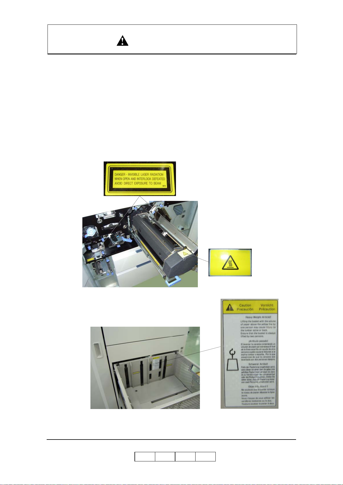
Caution Labels
Follwing figure shows the caution labels affixed on the printer.
Safety Summary -12
OG L
0 0
Page 21

SICHERHEIT ZUSAMMENFASSUNG
Allgemeine Sicherheit Richtlinien
Bevor Sie die Maschine laufen lassen, lesen Sie die f olgenden Anweisungen sorgfaltig:
■ Erlauben Sie alle Betriebsverfahren, die in diesem Handbuch b ereitgestellt
werden.
■ Lenken Sie besondere Aufmerksamkeit auf und folgen Sie der ganzer
Gefahrwarnung auf der Maschine und im Handbuch. Nichtbeachten kann
Verletzung oder Beschädigung der Maschine verursachen selbst.
■ Die Gefahrwarnungen, die auf den warnenden Aufklebern auf der Maschine
erscheinen, oder im H andbuch eine der folg enden Alarmüberschri ften haben S ie,
die aus einem Alarmsymbol und einem Sig nalbezirk bestehen, DANGER,
WARNING, or CAUTION.
DANGER! : zeigt eine in bedrohlicher Weise gefährliche Situation an, die, wenn
sie nicht vermieden wird, Tod oder ernste Verlet zung ergibt.
WARNING!: zeigt eine möglicherweise gefährliche Situation an, die, wenn sie
nicht vermieden wird, Tod oder ernste Verletzung ergeben kann.
CAUTION!: zeigt eine gefährliche Situ ation an, die, wenn sie nicht, kleine oder
gemäßigte Verletzung ergeben wird vermi eden wird oder kann,
oder ernste Beschädigung des Produktes.
Das Alarmsymbol, das nach links gezeigt wird, geht jedes
Kennzeichenwort fü r Gefahrwarnungen voran und erscheint in
Sicherheit bezogenen Beschreibungen im Handbuch.
Das Kennzeichenwort 'NOTE' wird verwendet, Warnungen darzust ellen, die nicht
direkt mit Personenschä dengefahren zusammenhängen.
■ Führen Sie keinen Betrieb oder Tätigkeit in keiner Weise anders als durch, wie in
diesem Handbuch zur Verfügung gestellt. Wenn im Zweifel, rufen Sie den
gekennzeichneten Kundendiensttechniker an.
■ Halten Sie im Verstand, dem die Gefahrw arnungen in diesem Handbuch oder auf
der Maschine ni cht jeden möglichen Fall abd ec k en k önnen, da es unmöglich ist,
alle Umstände vorher vorauszusa gen und auszuwerten. Seien Sie Ala rm und
verwende n Sie Ihren ge sunden Menschenversta nd.
OG L
Sicherheit Zusammenfassung -1
0 0
Page 22

SICHERHEIT ZUSAMMENFASSUNG
Gefahr-W ärmende Aussagen
WARNING Aussage
■ “Use of controls, adj ustments or performance of procedures othe r than those
specified in this manual may result in hazardous laser radiation exposure.” on
page Safet y Summa r y-5
■ “Connect the power plug only to a properly rated power outlet. Otherwise, a fire
or shock hazard may result.” on pa ge Safety Summary-7
■ “Never use multi-plug adaptors to plug multiple power plugs into the same power
source. Be sure to operate the printer on a sole-use receptacle. Multiple
connectors can cause overheating and a fire could result.” on page Safety
Summary-7
■ “The pri nter must be connected to the grounding power outlet for safe and proper
operation.” on page Safety Summary-7
■ “Apparatet må kun tilkoples jordet stikkontakt.” on page Safety Summary-7
■ “Apparaten skall ansulatas till jordat uttag när den ansluts till ett nätverk.” on
page Safet y Summa r y-7
■ “Für einen sicheren und ordnungsgemäßen Betrieb muß der Drucker an eine
geerdete Steckdose angeschlossen werden.” on pa ge Safety Summary-7
■ “These statements indicate a need for special care and safety to prevent you from
harming yourself when carrying, unpacking, assembling, installing, or operating
the product.” on page 1-2
■ “To avoid serious injury or death, disconnect the power cord from the power
outlet. Do not attempt to perform any servicing operation when the power cord is
connected to the power outlet. The AC line voltage is present inside the controller
enclosure regardless of the main power switch position.” on page 1-3
■ “Do not throw the toner bottle into a fire because it may suddenly burn, causing a
risk of fire or personal injury.” on page 4-6
■ “Dispose the toner bottle as incombustible waste.” on page 4-6
■ “Waste materials should be disposed of or incinerated under conditions which
meet all federal, state and local environmental regulations. Since regulations may
vary from one region to another, check with the agency that governs waste
disposal i n your area for proper proce dures.” on page 4-8
■ “Do not throw the developer bottle in to a fire because it may suddenly burn,
causing a risk of fire or personal injury.” on page 4-16
■ “The Fuser Unit is very hot. Do not touch any parts of the Fuser Unit ex cept those
parts which are used to replace the Fuser Cleaning Web.” on pag e 4-17
■ “The Fuser Unit is very hot. Do not touch any parts of the Fuser Unit ex cept those
parts which are used to remove the paper . It is better to use the Bamboo Tweezers
to remove the paper. (The Bamboo Tweezers is an attatced accessory.)” on
page 4-34
Sicherheit Zusammenfassung -2
OG L
0 0
Page 23

SICHERHEIT ZUSAMMENFASSUNG
CAUTION Aussage
■ “Never unplug or replug the printer while it is on.” on page Sa fety Summa ry-8
■ “Do not place the printer near heaters or volatile, flammable, or combustible
materials.” on page Safety Summ ary-9
■ “Once the printer is powered off, wait at least 5 seconds to next po wer on.” on
page 1-6
■ “If the printer does not power on, power off the printer, wait at least 30 seconds,
then power on the printer again.” on page 1 -6
■ “You must set the correct paper weight value. The incorrect paper weight value
may cause pa per jam.” on page 3-19
■ “Depending on amount of paper, the Basket is very heavy. Take care not to hurt
your back when lifting a heavy Basket.” on page 3-29
■ “Toner is not harmful to the human body, but if some toner has come in contact
with your skin or clothes, you should wash it immediately with cold water.” on
page 4-3
■ “The toner is not harmful to the human b ody. However, take care not to inhale or
swallow it because you may feel sick.” on page 4-6
■ “If the toner goes into your eyes, immediately rinse with running water. If
affected eyes are not rinsed, it may become injured. If the skin or clothing is
contacted, wash with soap and water” on page 4-6
■ “Hold the developer bottle when you turn the cap so that the bottle is not turned
together with the cap.” on page 4-10
■ “Hold the developer bottle when you turn the cap so that the bottle is not turned
together with the cap.” on page 4-13
■ “Incorrect setting of the Developer Bottle cause damage to the Developer Unit.
Make sure the setting of the Developer Bottle before go to next step.” on page 413
■ “If the developer is spilled out on the floor, the floor becomes very slippy. This
may result in a fall and/or injury. Clean up the spilled developer with a toner-safe
vacuum cleaner.” on page 4-15
■ “If the developer goes into your eyes, immediately rinse with running water. If
affected eyes are not rinsed, it may become injured. If the skin or clothing is
contacted, wash with soap and water” on page 4-15
■ “Surface of the Photoconductor Drum (OPC Sheet) is very sensitive. Carefully
remove a paper to avoid scratch the surface of the Photoconductor Drum.” on
page 4-32
■ “Power off the printer prior to cleanin g.” on page 4-51
■ “Do not use solvent on the printer. Using solvent may dissolve the plastic and
paint of t he printer.” on page 4-51
Sicherheit Zusammenfassung -3
OG L
0 0
Page 24

SICHERHEIT ZUSAMMENFASSUNG
■ “Do not us e cleaning sol utions to clean inside and around th e printer. Use only a
water-moistened cloth.” on page 4-51
■ “For cleaning up toner or developer spillage, use a s pecially-designed toner-safe
vacuum cleaner. If you use a regular vacuum cleaner, the drawn toner/developer
powder may scatter in the air. If you inhale or your eyes come into contact with
such powder, you may feel sick or injure your eyes. Further, the drawn toner/
developer powder may render the vacuum cleaner defective when it enters the
vacuum cle aner’s motor section.” on page 4-51
■ “The Paper Height Sensor in the Tray is sensitive. Carefully cleaning a Tray to
avoid a damage to the Paper Height Sensor.” on page 4-52
■ “Do not use paper that contains CaCO3 as it can drastically reduce fuser life.” on
page B-4
■ “Adhesive that comes in contact with the prin ter may contaminate the
photoconductor and the internal printer mechanism. To test label stock for
adhesive exposure, press a sheet of plain paper against a sheet of label stock . The
plain pap er should not adhere to the la bel stock at a ll.” on page B-12
Sicherheit Zusammenfassung -4
OG L
0 0
Page 25

SICHERHEIT ZUSAMMENFASSUNG
Laser-Sicherheit
Dieser Druc ker ist ein Laser-Produkt der Klasse 1 unter dem Radiation Per formance
Standard des U.S. Department of Health and Human Services (DHHS) gemäß dem
Radiation Control for Health and Safety Act 1968. Dies bedeutet, dass der Druc ker
keine gefährliche Laserstrahlung ausstrahlt.
Da die im Inneren dieses Druckers auftre tende S trahlung vollständ ig von den
Schutzgehäusen und externen Abdeckungen abgeschirmt wird, kann der Laserstrahl
während der richtig en Bedienun g durch den Anwender aus dem Drucker ni cht
austreten.
Das Center for Devices and Radiol ogical Health (CDRH) der U.S. Food and Drug
Administration implementierte V orschriften für Laser-Produkte im August 1976. Diese
Vorschriften treffen auf Laser-Produkte zu, die in den Vereinigten Staaten vertrieben
werden. Das Etikett an dem Drucker weist auf Über einstimmung mit den CDRHVorschriften hin und muss an in den V ereinigten Staaten vertriebenen Laser-Produkten
angebracht sein.
Der Drucker ist sowohl unter EN60825 als auch dem Code of Federal Regulations,
1040.10 des Title 21 als Laser-Produkt der Klasse 1 klassifiziert.
LOUKAN 1 LASERLAITE
CLASS 1 LASER APPARAT
Interne Laserstrahlu ng
Maximale Strahlungsleistung: 10mW x 4 Dioden
Wellenlänge: 780nm
WARNING!
Die Verwendung von Bedienelementen, Einstellungen oder die Ausführung
von Vorgängen, die nicht in dieser Anleitu ng beschrieben sind, kann dazu
führen, dass der Anwender gefährlicher Laserstrahlung ausgesetzt wird.
OG L
Sicherheit Zusammenfassung -5
0 0
Page 26

SICHERHEIT ZUSAMMENFASSUNG
Zertifizierungen
FCC-Hinweis
Dieses Gerät wurde getestet u nd in Übereinstimmung mit den Grenzwerten für
Digitalgeräte der Klasse A befunden, wie sie in T eil 15 der FCC-Vorschriften festgelegt
sind. Diese Grenzwerte sind so au sgelegt, dass ausreichender Schutz gegen schädliche
Interferenzen gewährleistet wird, wenn das Gerät in einem kommerziellen Umfeld
betrieben wird. Dieses Gerät generiert, verwendet und kann Radiofrequenzenergie
abstrahlen, wenn es nicht gemäß dieser Bedienungsanleitung installiert und verwendet
wird. Der Betrieb dieses Gerätes in einem Wohnbereich führt wahrscheinlich zu
schädlichen Interferenzen. In diesem Fall werden die Anwender aufgefordert, diese
Interferenzen auf eigene Kosten zu berichtigen.
Die Verwendung von abgeschirmte n Kabeln gemäß den Grenzw erten der Klasse A in
Unterabschnitt B von Teil 15 der FCC-Vorschriften ist erforderlich.
Nehmen Sie niemals andere als in dieser Bedienungsanleitung vorgeschriebene
Änderungen oder Modifikationen vor.
Sie werden wa hrs ch e i nli ch da s folge n de vo n de r F ede r al Com mu ni ca ti o ns
Commission veröffentliche Büchlein „How to Identify and Resolve Radio – TV
Interference Problems“ nützlich finden. Dieses Büchlein ist von dem U.S. Government
Printing Office, Washin gton, D.C. 20402, Stock No. 004-000-0035-4 erhältlich.
Kanadische Zertifikation
Dieses Digi talgerät de r Klasse A ent s pricht den ka nadischen Vorschriften ICES-003.
Cet appareil numérique de la classe A est conforme à la norme NMB-003 du Canada.
VCCI-Hinweise (Japan)
Dies ist ein Produkt der Klasse 1 gemäß dem Standard des Volun t ary Control Council
for Interference by Information Technology Equipment (VCCI). Falls dieses Gerät in
einem domestischen Umfeld verwendet wird, kann es zu Radiostörungen kommen.
Falls solche Störungen auftr eten, müssen Sie ggf. di e berichtigenden Akti onen
ausführen.
Sicherheit Zusammenfassung -6
OG L
0 0
Page 27

SICHERHEIT ZUSAMMENFASSUNG
Installation und Neuaufstellung des Druckers
Anforderungen an di e Stromversorgung
Nennspannung Nennfrequenz Nennstromstärke
200/208/220/230/240V 50/60Hz 21A
380/400/415V 50/60Hz 21A
Netzkabel
WARNING!
Stecken Sie den Netzstecker nur an eine Netzdose mit den
vorgeschriebenen Nennwerten an. Anderenfalls kann es zu Feuer- oder
Stromschlaggefahr kommen.
Verwenden Sie niemals Verzweigungsstecker, um mehrere Netzstecker an
die gleiche Netzdose anzuschließen . Betreiben Sie den Drucker nur von
einer separaten Netzdose. Mehrfachanschlüsse können zu Überhitzung
und Feuer füh ren.
Achten Sie darauf, dass d er Steckeranschluss frei von Staub ist. Bei feuchten
Bedingungen kann ein verschmutzter Stecker zu einem nicht vernachlässigbaren
Stromverbrauch führen, der Hitze erzeugen und über eine längere Zeitdauer zu einem
Brand führe n kann .
Um das Risiko von elektrischen Schlägen, persönlichen Verletzungen, Feuer u nd
Beschädigu ng des Druckers zu vermeiden:
■ Verwenden Sie nur das mit Ihrem Drucker mitg elieferte Netzkabel. Falls ein
Verlängerungskabel erforderlich ist, verwenden Sie nur ein Verlängerungskabel
mit den geeigneten Nennwerten.
Falls mit Ihrem Drucker kein Netzkabel mitgeliefert wurde, verwenden Sie die
folgend en Typen von Netzkabel:
❒ Für Nordamerika:
4 Dräht e, Typ SIT 4x12 AWG (4 x 4.0 mm²) oder dic k er
Nennwerte mindestens 300 V/25 A (mit Erdungsstecker)
❒ Für Europa :
5 Drähte, min. 5x4.0 mm
2
Harmonisiert (<HAR>), Nennwerte m indestens 300 V/25 A (mit
Erdungsstecker)
WARNING!
Für einen s i cheren und ordnungsgemäßen Betrieb muß der Dr uck er an
eine geerdete Steckdose angeschlossen werden.
OG L
Sicherheit Zusammenfassung -7
0 0
Page 28

SICHERHEIT ZUSAMMENFASSUNG
■ Ändern, zie hen, biegen, schaben oder beschädig en Sie nicht das Netzkabel.
Stellen Sie keine schweren Gegenstände auf dem Netzkabel ab.
■ Berühren Sie ni emals das Netzkabel mi t nas s en H änden.
■ Falls Rauch, übermäßige Hitze, ungewöhnliche Betriebsgeräusche oder ein
ungewöhnlicher Geruch an Ihrem Drucker auftreten sollten oder Flüssigkeit auf
den Drucker verschüttet wurde, schalten Sie den Drucker unverzüglich ab, und
ziehen Sie den Netzstecker.
■ Falls das Netzkabel beschädigt ist oder blanke Drähte freiliegen, lassen Sie das
Netzkabel erneuern. (Verwenden Sie niemals ein besch ädigtes Netzkabel.)
CAUTION!
Ziehen Sie niemals den Netzstecker ab, wenn die Stromversorgung des
Druckers eingeschaltet ist.
■ Wenn Sie den Drucker vom Netz abtrennen, ziehen Sie immer am Netzsteck er
und niemal s am Net z ka be l .
■ Schalten Sie unbedingt den Drucker aus, und ziehen Sie den Netzstecker von der
Netzdose ab, bevor Sie Reinigung s- oder Wartungsarbeiten im Inneren des
Druckers ausführen.
■ Falls Sie den Drucker für läng ere Zeit nicht verwenden, schalten Sie diesen aus,
und ziehen Sie den Netzstecker vo n der Netzdose ab.
■ Ziehen Sie den Netzstecker des Druckers einmal monatlich ab, und prüfen Sie,
dass:
❒ der Netzstecker richtig an die Netzdose angesteckt ist.
❒ das Netzkabel nicht beschädigt oder ausgefranst ist.
❒ d er Netzstecker nicht übermäßig erhitz t, verrostet oder verb ogen ist.
❒ d er Netzsteck er und die Netzdose frei von Staub sind.
NOTE:
Falls Sie ungewöhnliche Bedingungen feststellen sollten, wenden Sie sich
bitte an Ihren Kundendienst.
Sicherheit Zusammenfassung -8
OG L
0 0
Page 29

SICHERHEIT ZUSAMMENFASSUNG
Sichere Positionierun g des Druckers
Um das Risiko von elektrischen Schlägen, persönlichen Verletzungen, Feuer u nd
Beschädigu ng des Druckers zu vermeiden:
■ Schalten Sie den Drucker aus, bevor Sie das Schnittstellenkabel oder das
optionale Zubehör anschließen.
CAUTION!
Stellen Sie den Drucker niemals in der Nähe von Heizungen oder
flüchtigen, entzündbaren oder brennbaren Materialien auf.
■ Stellen Sie den Drucker auf einer waagerechten und stabilen Fläche auf, die das
Gewicht de s Druckers abstützen kann. Bei ge neigter Aufstellung kann der
Drucker herunterfallen und Verletzungen verursachen.
■ Stellen Sie den Drucker niemals an einem heiß en, feuchten, staubigen oder
schlecht belüfteten Ort auf.
■ Falls Sie den Drucker an einen anderen Ort bringen müssen, ziehen Sie vorher
unbedingt den Netzstecker von der Netzdose ab. Falls der Drucker mit
angeschl ossenem Netzkabel transportiert wird, kann das Netzkabel beschädigt
werden.
■ Falls Sie den Drucker an einen anderen Ort bringen müssen, neigen Sie diesen
niemals um mehr als 10 Grad. Bei übermäßiger Neigung kann der Drucker
umfallen und Verletzungen verursachen.
■ Falls Sie den Drucker über eine große Strecke transportieren müssen, wenden Sie
sich bitte an einen Kundendienst.
Umfeldgrenzwerte
■ Dieser Drucker gewährleistet Normalbetrieb innerhalb der nachfolgend
empfohlenen Umfel dgrenzwerte:
❒ Temperaturbereich: 16 °C bis 32 °C
❒ Luftfeuchtigkeitsbereich: 20 bis 80 % relative Luftfeuchtigkeit (ohne
Kondensation)
NOTE:
Plötzliche Temperaturschwankungen können die Druckqualität
beeinträchtigen. Schnelles Aufheizen eines kalten Raumes kann zu
Kondensation im Inneren des Druckers führen, wodurch die
Bildübertragung beeinträchtigt werden kann.
■ Setzen Sie dem Drucker keinem direkten Sonnenlicht aus, da anderenfalls das
Leistungsvermögen des Druckers nachlassen könnte.
OG L
Sicherheit Zusammenfassung -9
0 0
Page 30

SICHERHEIT ZUSAMMENFASSUNG
VORSICHTSMASSNAHMEN BEIM BETRIEB
■ Passen Sie auf, daß sich Krawatten, Ärmel, Hemden und langes Haar beim
Betrieb nicht im Drucker verfangen.
■ Berühren Sie nicht die gefährlichen Teile im Bereich der Aufkleber mit den
W arnhinweisen.
■ Schalten Sie den Druc ker nicht versehentlich ein, un d drücken Sie während des
Druckerbetriebs keine Schalter im Bedienerfeld.
■ Beriihren Sie bei eingeschaltetem Drucker unter keinen Umständen die Hochsp
annungsteile des Druckers, an denen Aufkleber mit W arnhinweisen angebracht
sind.
■ Vergewissern Sie sich, daß das Druckerpapier die Angaben für Materialen erfüllt.
Drucken auf Papier, das diesen Angaben nicht entspricht, kann zu Papierstaus und
Einbußen bei der Druckqualität führen. Versehentliches Berühren kann zu
Verletzungen führen.
■ Legen Sie das Papier sachgemäß in den Behälter ein, um Papierstaus und schiefen
Einzug des P a pie r s z u ve r me i d en.
■ Es ist underläßlich , daß Sie die in di esem Handbuch beschri ebenen
Verfahrensweisen un d Anweisungen befol gen, um die Leistung d es Drucker s zu
oprimieren und einen sicheren Betrieb zu gewährleisten.
Sicherheit Zusammenfassung -10
OG L
0 0
Page 31

SICHERHEIT ZUSAMMENFASSUNG
SICHERHEITSVORKEHRUNGEN
■ Halten Sie im Bereich des Druckers stets Ordnung. Verwenden Sie den Drucker
bei den richtigen Lichtverhältnissen (500-1,000 lux).
Sorgen Sie für ausreichenden Platz um den Drucker herum, damit die Behälter
herausgezogen werden kön nen. Im Druckerbereich wird folgender Platz benötigt:
Vorderseite: 1 Meter
Links, rechts und auf der Rückseite: 1 Meter
■ Legen Sie keine Gegenstände auf den Drucker.
■ Ôffnen Sie die Abdeckungen nicht während des Druck vorgangs. Versehentliches
Berühren beweglicher oder elektrischer Teile kann zu Verletzungen führen.
■ Seien Sie bei Arbeiten in Bereich der Fixiereinheit besonders vorsichtig.
Berühren Sie auf keinen Fall das Innere der Fixiereinheit. Die Fixiereinheit wird
sehr heiß (etwa 190
führen.
■ Toner und Entwickler bestehen aus pulverförmigen Partikeln. Vermeiden Sie das
Einatmen von Toner oder Entwickler, wenn Substanzen aus Versehen v erschüttet
werden und in der Luft zirkulieren. Werden diese Substanzen auf den Boden
verschüttet, entfernen Sie sie sofort rait einem mit Wasser angefeuchteten Tuch.
Belassen Sie diese Substanzen nicht auf d em Boden. Dies könnte zu Unfällen
führen, da Sie auf den schlüpfrigen Metallkügelchen ausrutschen könnten.
°C) und versehentliches Berühren kann zu Verletzungen
■ Führen Sie nur die in diesem Handbuch b eschriebenen Operationen aus.
Setzen Sie sich mit dem zuständigen technischen AuBendienst oder mit dem
Kundendienst in V erbindung, wenn Sie Operationen ausführen möchten. die nicht
in diesem Handbuch beschrieben sind.
■ Dieses Gerät erzeugt Ozon. Die langzeitige Belastung solite auf 0.1 ppm.
berechnet als 8-stündige mittlere Konzentration beschränkt sein. Gute Belüftung
gewhären und das Gerät nicht in einem kleinen Raum (kleiner als 27 Kubikmeter)
aufstellen. W ird es jedoch in einem kleinen Raum von weniger als 27 Kubikmeter
aufgestellt, so ist es erforderlich, die Luft öfters aufzufrischen.
OG L
Sicherheit Zusammenfassung -11
0 0
Page 32

SICHERHEIT ZUSAMMENFASSUNG
Behandlung der Druckerverbrauchsartikel
■ Bewahren S ie das Papier, den Toner und die anderen Ve r bra u chsartikel an einem
Ort auf, de r fre i von dir ekte m Sonn enlic ht und e ntfe rnt vo n Heiz ungen ist. L agern
Sie diese Artikel nur an einem trockenen, kühlen und sauberen Ort.
■ Bewahren Sie das aus der Verpackung entfernte und noch nicht in den Drucker
eingesetzte Papier in einen versiegelten Plastik beutel eingesetzt an einem kühlen,
trockenen Ort auf.
■ Falls Sie Ihre Hände mit Toner verschmutzen sollten, waschen Sie Ihre Hände
unverzüglich mit Seife und W a sser.
Vorsicht Aufkleber
Folgende A bbildung zeigt die Vorsicht Aufkleber, die auf dem Drucker hinzugefügt
werden.
Sicherheit Zusammenfassung -12
OG L
0 0
Page 33

About This Manual
This manual provides easy access to the information you need to operate the 156PPM
(Pages Per Minute) laser printer.
NOTE:
This User’s Guide is intended to be viewed online. W hen viewing it online,
use the bookmarks and page reference links for easy navigation
throughout the do c ume n t .
To find out about a specific topic, refer to:
■ SAFETY INFORMATION – For safety information and printer characteristics,
including environmental and electrical requirements.
■ Chapter 1: Printer Overview – For printer components and features.
■ Chapter 2: Operator Control Panel – To access and use the liquid crystal display
(LCD) window and the menus screens.
■ Chapter 3: Paper Handling – For media recommendations and paper handling
procedures.
Introduction
Audience
This manual is written for those persons responsible for operating the printer. A basic
understanding of computer equipment and its operations is required.
■ Chapter 4: Care and Maintenance – For detailed instructions on replacing
consumables, clearing paper jams, and cleaning and maintaining the printer.
■ Chapter 5: Troubleshooting – For information on printing problems and printer
error and warning messages.
■ Chapter 6: Web Utilities – For information on accessing th e printer via the
Internet or your company’s Intranet.
■ Appendix A: Specifications – For printer specifications.
■ Appendix B: Paper Specifications – For me dia specifications and printing
guidelines.
■ Glossary – For definitions of terms and acronyms.
OG L
Introduction 0-1
0 0
Page 34

Manual Conventions
The following conventions are u sed in this manual:
■ Bold and Italics are used sparingly for emphasis.
■ Information yo u enter: Looks Like This.
■ Key Names (or Labels): Look Like This.
■ System message s: Look Like This.
■ Variable user information: Looks Like This.
Pay particular attention to Notes, Cautions, and Warnings. These alert you to critical
information, as follows:
NOTE:
Provides important additional information.
CAUTION!
Alerts you to an operat ing procedure, practice, or condition that, if not
strictly observed, might result in damage to the equipment.
WARNING!
Alerts you to an operat ing procedure, practice, or condition that, if not
strictly observed, can result in safety hazards to personnel, severe injury,
or loss of life.
For More Information
Refer to the following related documents for more details about your printer.
■ Installation Guide
■ Engine Maint enance Manual
■ Controller Maintenance Manual
■ Parts Catalog
0-2 Introduction
OG L
0 0
Page 35

What This Chapter Provides
This chapter describes the parts and functions of the printer.
■ Printer Features
■ External View of the Printer
■ Internal View of the Printer
■ Powering On the Printer
■ Powering Off the Printer
■ Space Required for Installation
Chapter 1
Printer Overview
OG L
Printer Overview 1-1
0 0
Page 36

Printer Features
The printer is a high-speed, heavy duty laser printer for a 1.5M page/month printing
environment. It incorporates a wide variety of features:
■ High-Speed and High-Quality Printing.
❒ Print speed is up to 156 pages per minute (ppm), A4/Letter/Legal (Simplex).
❒ The printing output is at a reso lut i o n of 60 0 dots per inch (dpi), assuri ng
razor-sharp graphic and text output, even at very small point sizes.
■ Flexible Paper Source and Delivery.
Paper Source:
❒ Standard – One 2,500-sheet and one 1,000-sheet universal paper trays.
❒ Option – High Capacity Feeder with 3,000 to 12,000-sheet capacity.
Paper Delivery:
❒ Standard – Contai ner St acker with 2,000 to 4,000-sheet capac ity and sta cking
capability.
❒ Option – Additional Container S tacker with 2,000 to 4 ,000-sheet capacity and
stacking capability.
■ Multiple Original Printing (MOP) – for printing of multiple collated document
sets without multiple file transfers. Processes PCL and PostScript jobs once,
stores the images on disk, and prints each set from disk (after the first set).
■ Virtual Printer Technology (VPT) – allows a single printer to offer print services,
or virtual printers, each of which is conf ig ured by the Network Administrator.
■ Web Utili ties – for remote access to the printer through the Internet or your
company’s Intranet.
■ Ergonomic operation.
❒ The easy-to-read display clearly shows the operational status of the pr inter.
1-2 Pri nter Overview
OG L
0 0
Page 37

■ High-volu me pr i nti ng .
❒ Two standard paper trays with appr oximately 3,500-sheet capacity total.
❒ Optional High Capacity Feeder (HCF) adds up to 12,000 additional sheets.
❒ Together they allow continuous printing of up to 15,500 sheets.
■ Supports a wide-range of media types (plain, bond, letterhead, special application,
recycled, labels) and sizes. See “Paper” on page 3-2 for more information.
■ Printer Language Support.
❒ PCL5e and PCL XL printer langua g e.
❒ PostScript Level III (Adobe) printer language.
❒ P DF and TIFF files printing.
NOTE:
PDF Files printing is only supported for PDF Version 1.3.
■ Network.
❒ Ethernet 10/100/1000 Base-T with onboard network
❒ Additional Ethernet 10/100 Base-T with Multi-protocol NIC option.
■ Network Protocol.
❒ TCP/IP, LPR/LPD and IPP with onboard network.
❒ TCP/IP, LPR/LPD, NetWare IPX/SPX, Ethertalk with Multi-protocol NIC
option.
■ Easy installation of additional fonts and macros using the PCL Startup File.
I/O Configurations
■ Ethernet 10/100/1000 Base-T with onboard network.
■ Additional Ethernet 10/100Base-T with Multi-protocol NIC option.
Operator Control Panel
The Operator Control Panel (OCP) is your physical interface to the printer's features
and functions. From the control panel, you can monitor the printer's operating status
and configure the specific printer functions.
See Chapter 2 for detailed information about the OCP.
OG L
Printer Overview 1-3
0 0
Page 38

External View of th e Printer
The following illustration shows the printer with an optional Container Stacker,
optional High Capacity Feeders and optional Attention Light are installed.
7. High Capacity Feede r 1
10. High Capacity Feeder 2
12. HCF2 Upper Tray
11. HCF2 Lower Tray
3. Toner Supply Cover
9. HCF1 Upper Tray
8. HCF1 Lower Tray
Figure 1-1. External View of the Printer
1. Power Switch
6. Tray 2
4. Operator Control Panel
13. Sample Tr ay
2. Front Cover
5. Tray 1
20. Attention Light
14. Container Stac ker 1
17. Container Stacker 2
19. Container 2
Upper T ray
15. Container1 Lower Tray
16. Container1 Upper Tray
18. Container 2
Lower Tray
Table 1-1. External Vie w of the Print er
Key Component Description
1 Power Switch Press to turn the printer on and off.
2 Front Cover Open to replace units, clear paper jams, or clean the printer.
3 Toner Supply Cover Open to replenish the toner supply.
4 Operator Control Panel (OCP) Displays printer status and menu information.
5 Tray 1 Holds up to 2,500 sheets of paper.
6 Tray 2 Holds up to 1,000 sheets of paper.
7 High Capacity Feeder 1 Two 3,000-sheet input trays.
8 HCF1 Lower Tray Holds up to 3,000 sheets of paper.
9 HCF1 Upper Tray Holds up to 3,000 sheets of paper.
10 High Capacity Feeder 2 Two 3,000-sheet input trays.
11 HCF2 Lower Tray Holds up to 3,000 sheets of paper.
12 HCF2 Upper Tray Holds up to 3,000 sheets of paper.
13 Sample Tray 100-sheet output tray
14 Container Stacker 1 Two 2,000-sheet output trays
15 Container1 Lower Tray Stacks up to 2,000 sheets of paper.
16 Container1 Upper Tray Stacks up to 2,000 sheets of paper.
17 Container Stacker 2 Two 2,000-sheet output trays
18 Container2 Lower Tray Stacks up to 2,000 sheets of paper.
19 Container2 Upper Tray Stacks up to 2,000 sheets of paper.
20 Attention Light Indicates error, warning and printer ready status.
1-4 Pri nter Overview
OG L
0 0
Page 39

Internal View of the Printer
1. Toner Supply Cover
2. Developer Duct
3. Drum Unit
4. Fuser Unit
6. SF Cover
5. Toner Bottle / Toner Bag
7. Main AC Power Switch
Figure 1-2. Internal V iew of the Printer
Table 1-2. Internal View of the Printer
Key Component Description
1 Toner Supply Cover Open this cover when supplying the new toner.
2 Developer Duct
3 Drum Unit OPC drum.
4 Fuser Unit Fuses the toner on the paper.
5 Toner Bottle/Toner Bag Collect the waste toner.
6 SF Cover Open this cover when replacing the Fine Filter.
7 Main AC Power Switch Turn the printer main AC power on and off
Mount the developer bot tle onto th e devel op er du ct to repla ce
consumed developer
OG L
Printer Overview 1-5
0 0
Page 40

Powering On the Printer
The printer has two power switches, the Main AC Power Switch and the Power
Switch. The location of switches are shown below. Both switches are marked “I” for
power on.
Main AC Power Switch
When the printer is powered on, the prin ter go through a power-up sequence that takes
approximately 5 minutes. During the power-up sequence, the printer runs a series of
internal tests.
CAUTION!
Once the printer is powered off, wait at least 5 seconds to next power on.
If the printer does not power on, power off the printer, wait at least 30
seconds, then power on the printer again.
Power Switch
Figure 1-3. Powering On the Printer
1-6 Pri nter Overview
OG L
0 0
Page 41

Power ing Off the Printer
The printer should only be powered off when it is in a “Ready” state; that is, there are
no jobs printing or pr ocessing. The following OCP displays indicate norm al
conditions. In these conditions, wait until printing is complete and the printer is
Ready, then switch off the Power Switch.
Figure 1-4. Normal Conditions
If the printer status is Pause/Offline, touch the “” button to return printer to a Ready
status bef ore pow eri n g off.
Figure 1-5. Pause/Offline
OG L
Printer Overview 1-7
0 0
Page 42

Clearing Error Con di tio ns
OCP Alternates between Ready and Processing
1. Cancel the print job(s). For detail of canceling print job,
Figure 1-6. OCP Alternates between Ready and Processing
E0XX, E1XX Error
1. Correct the error and touch the “” button on the OCP display.
2. Wait until printing is complete and the printer returns to Ready, then switch off
the main power.
1-8 Pri nter Overview
Figure 1-7. E0XX, E1XX Error
OG L
0 0
Page 43

E2XX, EC#XX Call for Service Error
1. Touch the “” button on the OCP display .
2. Wait until printing is complete and the printer returns to Ready.
Figure 1-8. Call for Service Error
3. If the Call for Service error persists, cancel the print job(s) , power off the printer,
and contact your authorized service technician.
OG L
Printer Overview 1-9
0 0
Page 44

Space Required for Installation
)
Install the printer in a well-ventilated place and keep around the printer as shown
below for safe and effective operation.
Required Sp ace (for Maximum Configuration
1264 905 905
968 1318
Figure 1-9. Space Required for Installation
(Top View)
1-10 Printer Overview
OG L
0 0
Page 45

What This Chapter Provides
This chapter contains information on the following topics.
■ Description of Control Panels
■ OCP Menu Icons and Buttons
■ Using the OCP Menus
■ OCP Menu Struc ture
■ Sub Panel
Chapter 2
Control Panels
OG L
Control Panels 2-1
0 0
Page 46

Description of Control Panels
The Operator Control Panel (OCP) is a touch panel display that you use to set up print
options and monitor job and printer status. It is also used by the Network Administrator
to configure the printer and by the Service Technician to perform maintenance on the
printer.
This prin ter also have sub panel equipped to eac h Input and Output Trays. Sub panel
has some functions to each Input and Ou tput Tr ays.
Sub Panel (Input Tray)
Operator Control Panel
Sub Panel
(Output Tra y)
Figure 2-1. Operator Control Panel
2-2 Control Panels
OG L
0 0
Page 47

OCP Menu Icons and Buttons
The menus are accessed via the touch panel. Each OCP menu consists of icons and
buttons that you use to make selections. The icons and buttons are defined below . See
“Main Menu” on page 2-8 for more icons.
Table 2-1. OCP Menu Icons and Buttons
Icon or
Button
?
i
Name Function
Help Touch to display Help on the current screen.
Information From the Main Menu, displays infor ma ti on about the printer and
Pause/Offline Touch to pause the printer.
Resume/Online When the printer is offline, touch to return to Ready status.
Return to Main
Menu
Previous Menu Touch to cancel the current selection and return to the previous screen
More Options Touch to display additional options for the current selection.
Enter or Accept Confirm or Done. Touch to confirm your selection and return to the
consumables.
From relevant scre ens, displ ays an illus tr ation o f the p a per trays
or finisher trays.
Touch to cancel the current selection and return to the Main Menu.
or menu.
previous screen or menu.
Sample Touch to duplicate a current prin ti ng p a ge a nd o utput to the sampl e tra y.
Clear Button Touch to erase entire entry.
Delete Button Touch to erase last character entered.
–
Ten Key Use to enter numeric values.
Brightness Use to adjust backlight value of the OCP display.
Contrast Use to adjust the contrast level of the OCP display.
Status Bar Displays the current screen name and/or any system messages.
Control Panels 2-3
OG L
0 0
Page 48

Using the OCP Menus
There are 4 types of OCP Menu displays.
■ Option Button
■ Ten Key Pad
■ Change Button (+ / -)
■ Change But t on (Ena b l e /D i s abl e )
A brief description of each m enu and how to use it follows.
Using the Option Button Menu
The image below is a sample of a menu with Option buttons. The status bar indicates
the current setting. In this sample there is a More Options button indicating there are
more options to choose from on the following page.
Status Bar
Option Buttons
Previous Menu
More Options
Figure 2-2. Option Button M enu
Enter/Accept
To use this menu,
1. Touch the Option button. The selection is highlighted.
2. Touch the Enter/Accept button to activate the selection.
NOTE:
The selection will be ignored if the Enter/Accept button is not touched, or
if any other button is touched prior to touching Enter/Accept.
2-4 Control Panels
OG L
0 0
Page 49

Using the Ten Key Pad Menu
The image below is a sample of a menu with a ten key pad. It is used to enter numeric
values.
Status Bar
Text Box
Ten Key Pad
Figure 2-3. Ten Key Pad Menu
Erase Entire Entry
Erase Last Digit
Unit Value
Previous Menu
Enter/Accept
To enter a value,
1. Touch the appropriate numbers on th e pad. The value appears in the T ext Box.
2. Touch the desired Unit Value button (if applicable).
3. Touch the Enter/Accept button to activate the entry.
NOTE:
The entry will be ignored if the Enter/Accept button is not touched, or if
the Previous Menu button is touched prior to touching Enter/Accept.
OG L
Control Panels 2-5
0 0
Page 50

Using the + / - Change Button Menu
The image below is a sample of a menu with a + / - change button. It is used to increase
and decrease the OCP brightness and contrast. The current value is displayed to the
right of the icon.
Decrease -
Increase +
Figure 2-4. + / - Change Button Menu
10
10
Current Value
3
Previous Menu
Enter/Accept
To increase or decrease th e value,
1. Touch the + or - to adjust brig htness or contrast. The numeric value and the
display will change immediately.
Touch the Enter/Accept button to activate setting.
NOTE:
The setting will be ignored if the Enter/Accept button is not touched, or if
the Previous Menu button is touched prior to touching Enter/Accept.
2-6 Control Panels
OG L
0 0
Page 51

Using the Enable/Disable Change Button Menu
The image below is a sample of a menu with an Enable/Disable toggle. It is used to turn
an option on or off.
Enabled
40 seconds
Options
Figure 2-5. Enable/Disable Change Button Menu
1. Touch the Option Button to toggle between enable and disable. The current
setting appears to the right.
2. When you are finished, touch the Previous Menu button.
NOTE:
The Enter/Accept button is not used fo r Enable/Disable options. The
setting is activated immediately.
Disabled
Disabled
Middle
Current Status
Previous Menu
OG L
Control Panels 2-7
0 0
Page 52

OCP Menu Structure
The OCP menu is structur ed as show n on the fo llowing pages. A top level me nu screen
is shown followed by a description of the options on the screen. A table that outlines
the complete structure of the menu is also provided. Each box in the table represents an
OCP display menu. Use this information to assist you in setting printer options.
Main Menu
The Main Menu screen is shown below. A description of the icons that make up the
screen follows.
Status Bar
Printer Menu
Setup Menu
Jobs Menu
Printer Menu
Touch to display the Printer Menu.
Setup Menu
Touch to display the Setup Menu.
Reports Menu
Touch to display the Reports Menu.
Help
Current Screen
Information
Reports Menu
Sample
Pause/Offline
Figure 2-6. Main Menu
Jobs Menu
Touch to display the Cancel Printing screen and view a list of all jobs.
For other buttons or i cons, see “Using the Option Button Menu” on page 2-4.
2-8 Control Panels
OG L
0 0
Page 53

Information Menu
When you touch the information icon on the Main Menu this screen is displayed. You
can use it to determine the current settings and status o f the options described below.
See Table 2-2 on page 2-10 for the complete Information Menu structure.
Printer
Touch to display information about the engine and controller so f tware revision, error
counts, and the current p aper type and source settings.
Consumables
Figure 2-7. Information Menu
Displays the status of the consumables: Toner, Developer Mix., OPC Sheet, and OPC
Sheet Counter.
Usage
Displays current information regarding print density, preventative maintenance, and
page coun ts.
Paper Output
Displays current information regarding the Output Tray of the printer.
Network
Displays information such as MAC and IP Address, Gateway Address, Subnet Mask
and HTTP Port.
OG L
Control Panels 2-9
0 0
Page 54

Table 2-2. Information Menu S tructure
Level 1 Level2 Level 3 Level 4
Informati on Printer 1 Size, Status, Type, Weight
2 Size, Status, Type, Weight
HCF1 Lower (Note1) Size, Status, Type, Weight
HCF1 Upper (Note1) Size, St atus, Type, Weight
HCF2 Lower (Note1) Size, Status, Type, Weight
HCF2 Upper (Note1) Size, St atus, Type, Weight
Printer Graphic
Default Paper Source
Error Count of This Period
Controller Revision
Consumable Toner Normal/Low
Developer Mix (current/limit k)
OPC Sheet (current/limit k)
OPC Sheet Counter (curr ent/limit k)
Usage Toner Cov erage (current %)
PM Due In (current k)
Total Page Counter (current k)
Process Counter (current k)
Paper Output 1L Paper Size, Bask et Information, Basket Size
1U Paper Size, Basket Information, Basket Size
2L (Note2) Paper Size, Basket Information, Basket Size
2U (Note2) Paper Size, Basket Information, Basket Size
Printer Graphic
Network 10/100/1000B-T MAC Address
IP Address
Subnet Mask
Gateway Address
HTTP Port
10/100B-T NIC MAC Address
IP Address
Subnet Mask
Gateway Address
HTTP Port
Note 1: This display is only available when the HCF is installed.
Note 2: This display is only available when the additional stacker is installed.
2-10 Control Panels
OG L
0 0
Page 55

Printer Menu
When you select Printer icon from the Main Menu, this screen is displayed. You use
the Printer Menu to gain access to the printing options described below. See Table 2-3
beginnin g on pa ge 2-15 for the com plete Printer Menu structure.
Paper Source
■ Default
Defines th e defa ult paper tr ay. Use this wh en the paper so urce is not d esig nated by
a host command. If a command from the host defines the paper source, th e OCP
setting is ignored. When “AutoSelect” is selected, tray is automatically selected
according to paper size and/or paper type defined by host.
Figure 2-8. Printer Menu
■ Paper Size
When Paper Size is selected the pap er size of the currently selected paper source
is displayed. When the “Custom Size Switch” in the tray is set to “Stand ard”,
paper size is automatically detected.
T o use the OCP to set the paper size to something other than the standard sizes, set
the Custom Size Switch in the tray to “Custom”, then s elect Paper Size on the
OCP. See “Paper Sizes, Paper Weights, Paper Types and Paper Color” on page 3-
3 for more information.
■ Paper Type
Defines the paper type to desired input tray. The paper type screen displays
currently selected paper type, and press the option buttons to change to d e sir ed
paper type. See “Paper Sizes, Paper Weights, Paper Types and Paper Color” on
page 3-3 for more information.
■ Paper Color
Defines the paper color to desired input tray. The paper color screen displays
currently selected paper color, and press the option buttons to change to desired
paper color. See “Paper Sizes, Paper W eights, Paper Types and Pap er Color” on
page 3-3 for more information.
OG L
Control Panels 2-11
0 0
Page 56

■ Paper Weight
Defines the paper weight to desired input tray. The paper weight screen displays
currentl y d efined paper weight, and redefi ne to desired paper weight by this
screen. See “Paper Sizes, Paper Weights, Paper Types and Paper Color” on
page 3-3 for more information.
■ HV Adjust
The print position can be adjusted vertically and horizontally using the HV Adjust
option. The white arrow on the HV Adjust screen indicates paper feed direction.
The adjustment can be set to millimeters or inches and the range is -6.3 to +6.3
millimeters (-0.25 to +0.25 inches) in increments of 0.1 millimeter (0.01 inch).
Difference positions can be set for front and back side in duplex printing mode.
See “Setting the HV Adjust Values” on page 3-21 for more information.
■ Table Adjust
Defines the table height setting of the each input tray. This option can be adjusted
to five settings: +2, +1, Normal, -1 or -2. See “Setting the Table Adjust” on
page 3-23 for more information.
■ Paper Moisture
Defines the Paper Moisture setting to each input tray. This option can be adjusted
to four settings: Highest, Higher, Normal and Lower. See “Setting the Paper
Moisture” on page 3-25 for more information.
■ HCF Tray Control
Paper Output
■ Default Output
■ Stacking Level
Defines the HCF tray control mode if the optional HCF is installed. This option
can be set to the “Normal Pick Mode” or the “Prior Pick Mode”.
❒ Normal Pick Mode
Printer picks paper fro m the HCF by no rm al meth od .
❒ Prior Pick Mode
Printer picks paper from the HCF prior to the standard tray, and paper is
waiting to print on the paper path. The tray switching time to the HCF is
shorter than Normal Pick Mode, but more papers might be wasted than
Normal Pick Mode when paper jam is occurred.
Use this when the output tray is not designated by a host command. If a command
from the host defines the output tray, the OCP setting is ignored.
Defines the Upper limit of the stackin g level of each output tray. This option can
be adjusted to three settings: 50%, 75% or 100%.
2-12 Control Panels
OG L
0 0
Page 57

Options
■ Exit Jam Recovery
Can be set to enable or disable. When set to enable, the p rinter will reprint pages
that were improperly printed due to a paper jam.
■ Wait Timeout
Defines the waiting period (in seconds) from reception of last data to the
reception of next data. If data is not received within the defined period, the job is
cancelled. A command from the host will override th e OCP setting.
■ LPD Queuing
Can be set to enable or disable. The factory default is disabled.
■ Duplex Always
Can be set to enable or disable. When set to enable, the printer will always prints
the job by duplex mode.
■ Print Density
Print Density can be adjusted to five settings: Lig ht, Semi-Light, Middle, SemiDark or Dark
■ Auto Proof Sample
PostScript
This function provides the automatic proof sample printing instead of manually
pressing the “Sample” button on the OCP . Print interval of the sample page can be
set from 0 to 5,000 every 5 00 sheet (0, 500, 1,000, 1,500, ... 5,000). For example ,
If interval is set to “500”, then printer auto matically duplicates the proof sample
to the Sample Tray every 500 sheet during printing. If the interval is s et to “0”,
this function is disabled.
■ Print Errors
Can be set to enable or disable. When set to enable, the printer will prints error
page when PostScript error is o ccurred.
■ Best Fit
Can be set to enable or disable. When set to en able, the printer will prints the p age
image to fit the paper size.
■ Job Timeout
Defines the time limit (in seconds) for processing of the PostScript job.
■ Halftone Density
Halftone Density can be adjusted to three settings: Light, Medium or Dark. .
NOTE:
The Halftone Density menu is only displayed when the Ha lftone Selection
in the Service menu is enabled.
Control Panels 2-13
OG L
0 0
Page 58

Test Pri n t
PCL
Use this button to prints the test pattern for checking the print quality or th e print
position. Following test patterns are available in this menu.
■ Cross Pattern
This option prints the combination of Horizontal/Vertical/Diagonal lines for
checking the print position. This pattern is printed by duplex.
■ Raster Pattern
This option prints the 8 page of the raster pattern and 8 page of th e blank pages
(total 16 pages) for checking the print quality. This pattern is printed by simplex.
■ Wide A4
Can be set to enable or disable. When set to enable, th e printer changes the
margin/printable area of A4 paper so that 80 10-pitch characters may be printed
on a line.
■ Requested Tray
Defines the printer behavior when requested tray is specified in jobs.
❒ Exclusively
Printer should print from the requested tray only.
❒ First
Printer should print from the requested tray first.
2-14 Control Panels
OG L
0 0
Page 59

Table 2-3. Printer Menu Structure
Level 1 Level 2 Level 3 Level 4 Level 5 Level 6
Printer Paper Source Default
(Note 1)
Paper Size
(Note 1)
Paper Type
(Note 1)
Auto Select
1
2
HCF1 Lower
(Note2)
HCF1 Upper
(Note2)
HCF2 Lower
(Note2)
HCF2 Upper
(Note2)
1
2
HCF1 Lower
(Note2)
HCF1 Upper
(Note2)
HCF2 Lower
(Note2)
HCF2 Upper
(Note2)
1
2
HCF1 Lower
(Note2)
HCF1 Upper
(Note2)
HCF2 Lower
(Note2)
HCF2 Upper
(Note2)
Folio SEF, Folio LEF, Super B SEF,
Executive LEF, Letter SEF, A4 SEF,
Legal SEF, Custom Size (Note 3)
Folio SEF, Folio LEF, Super B SEF,
Executive LEF, Letter SEF, A4 SEF,
Legal SEF, Custom Size (Note 3)
Folio SEF, Folio LEF, Super B SEF,
Executive LEF, Letter SEF, A4 SEF,
Legal SEF, Custom Size (Note 3)
Folio SEF, Folio LEF, Super B SEF,
Executive LEF, Letter SEF, A4 SEF,
Legal SEF, Custom Size (Note 3)
Folio SEF, Folio LEF, Super B SEF,
Executive LEF, Letter SEF, A4 SEF,
Legal SEF, Custom Size (Note 3)
Folio SEF, Folio LEF, Super B SEF,
Executive LEF, Letter SEF, A4 SEF,
Legal SEF, Custom Size (Note 3)
Plain, Bond, Color, Label, Letterhead,
Preprinted, Prepunched, Recycled,
Tracing Paper, Special, Other
Plain, Bond, Color, Label, Letterhead,
Preprinted, Prepunched, Recycled,
Tracing Paper, Special, Other
Plain, Bond, Color, Label, Letterhead,
Preprinted, Prepunched, Recycled,
Tracing Paper, Special, Other
Plain, Bond, Color, Label, Letterhead,
Preprinted, Prepunched, Recycled,
Tracing Paper, Special, Other
Plain, Bond, Color, Label, Letterhead,
Preprinted, Prepunched, Recycled,
Tracing Paper, Special, Other
Plain, Bond, Color, Label, Letterhead,
Preprinted, Prepunched, Recycled,
Tracing Paper, Special, Other
Length: 7-18”
(178-457.2mm)
Width: 8-14”
(203-355.6mm)
Length: 7-18”
(178-457.2mm)
Width: 8-14”
(203-355.6mm)
Length: 7-18”
(178-457.2mm)
Width: 8-14”
(203-355.6mm)
Length: 7-18”
(178-457.2mm)
Width: 8-14”
(203-355.6mm)
Length: 7-18”
(178-457.2mm)
Width: 8-14”
(203-355.6mm)
Length: 7-18”
(178-457.2mm)
Width: 8-14”
(203-355.6mm)
Note 1: Commands from the Host override OCP settings.
Note 2: This menu is displayed only when the HCF is installed.
Note 3: This menu is available only when the Custom Size Switch in is set to “Custom”.
Control Panels 2-15
OG L
0 0
Page 60

Table 2-3. Printer Menu Structure - Continued
Level 1 Level 2 Level 3 Level 4 Level 5 Level 6
Printer Paper Source Paper Color
(Note 1)
Paper
Weight
(Note 1)
HV Adjust
Table Adjust
1 White, Pink, Yellow,
Buff, Goldenrod, Blue,
Green, Custom
2 White, Pink, Yellow,
Buff, Goldenrod, Blue,
Green, Custom
HCF1 Lower
(Note 2)
HCF1 Upper
(Note 2)
HCF2 Lower
(Note 2)
HCF2 Upper
(Note 2)
White, Pink, Yellow,
Buff, Goldenrod, Blue,
Green, Custom
White, Pink, Yellow,
Buff, Goldenrod, Blue,
Green, Custom
White, Pink, Yellow,
Buff, Goldenrod, Blue,
Green, Custom
White, Pink, Yellow,
Buff, Goldenrod, Blue,
Green, Custom
1 60-199gm
(33-110 lb. index,
16-53 lb. bond)
2 60-199gm
HCF1 Lower
(Note 2)
HCF1 Upper
(Note 2)
(33-110 lb. index,
16-53 lb. bond)
60-199gm
(33-110 lb. index,
16-53 lb. bond)
60-199gm
(33-110 lb. index,
16-53 lb. bond)
HCF2 Lower
(Note 2)
HCF2 Upper
(Note 2)
60-199gm
(33-110 lb. index,
16-53 lb. bond)
60-199gm
(33-110 lb. index,
16-53 lb. bond)
2
2
2
2
2
2
Front H/V Direction -0.25” to +0.25”
Back H/V Direction -0.25” to +0.25”
1:Thick +2/+1/Norm al/-1/-2
1:Thin +2/+1/Normal/-1/-2
2:Thick +2/+1/Norm al/-1/-2
2:Thin +2/+1/Normal/-1/-2
HCF1L:Thick
+2/+1/Normal/-1/-2
(Note 2)
HCF1L:Thin
(Note 2)
HCF1U:Thick
(Note 2)
HCF1U:Thin
+2/+1/Normal/-1/-2
+2/+1/Normal/-1/-2
+2/+1/Normal/-1/-2
(Note 2)
HCF2L:Thick
+2/+1/Normal/-1/-2
(Note 2)
HCF2L:Thin
(Note 2)
HCF2U:Thick
(Note 2)
HCF2U:Thin
(Note 2)
+2/+1/Normal/-1/-2
+2/+1/Normal/-1/-2
+2/+1/Normal/-1/-2
Color 1, Color 2, Color 3, Color 4,
Color 5, Color 6, Color 7, Color 8,
Color 9, Color 10, Color 11, Color 12,
Color 13, Color 14, Color 15, Color 16
Color 1, Color 2, Color 3, Color 4,
Color 5, Color 6, Color 7, Color 8,
Color 9, Color 10, Color 11, Color 12,
Color 13, Color 14, Color 15, Color 16
Color 1, Color 2, Color 3, Color 4,
Color 5, Color 6, Color 7, Color 8,
Color 9, Color 10, Color 11, Color 12,
Color 13, Color 14, Color 15, Color 16
Color 1, Color 2, Color 3, Color 4,
Color 5, Color 6, Color 7, Color 8,
Color 9, Color 10, Color 11, Color 12,
Color 13, Color 14, Color 15, Color 16
Color 1, Color 2, Color 3, Color 4,
Color 5, Color 6, Color 7, Color 8,
Color 9, Color 10, Color 11, Color 12,
Color 13, Color 14, Color 15, Color 16
Color 1, Color 2, Color 3, Color 4,
Color 5, Color 6, Color 7, Color 8,
Color 9, Color 10, Color 11, Color 12,
Color 13, Color 14, Color 15, Color 16
(-6.3 to +6.3mm)
(-6.3 to +6.3mm)
Note 1: Commands from the Host override OCP settings.
Note 2: This menu is displayed only when the HCF is installed.
2-16 Control Panels
OG L
0 0
Page 61

Table 2-3. Printer Menu Structure - Continued
Level 1 Level 2 Level 3 Level 4 Level 5 Level 6
Printer Paper Source Paper Moisture
HCF Tray
Control (Note 2)
Paper Output Default Output
(Note 1)
Stacking Level
Options Exit-Jam
Recovery
Wait Timeout
LPD Queuing
Duplex-Always
Print Density
Auto Proof
Sample
PostScript Print Errors
Best Fit
Job Timeout
Halftone
Density (Note
3)
Test Print Cross Patte rn
Raster Pattern
PCL Wi d e A4
Requested Tray
1 Highest/Higher/
2 Highest/Higher/
HCF1 Lower
(Note 2)
HCF1 Upper
(Note 2)
HCF2 Lower
(Note 2)
HCF2 Upper
(Note 2)
Normal Pick Mode
Prior Pick Mode
Container 1 Lower
Container 1 Upper
Container 2 Lower
(Note 1)
Container 2 Upper
(Note 1)
1 Lower :Short 100%/75%/50%
1 Lower :Long 100%/75%/50%
1 Upper :Short 100%/75%/50%
1 Upper :L ong 100%/75%/50%
2 Lower :Short
(Note 1)
2 Lower :Long
(Note 1)
2 Upper :Short
(Note 1)
2 Upper :L ong
(Note 1)
Enable/Disable
0-999 seco nds
Enable/Disable
Enable/Disable
Light/Semi-Light/
Middle/Semi-Dark/
Dark
0, 500, 1,000, 1,500,
2,000, 2,500, 3,000,
3,500, 4,000, 4,500,
5,000
Enable/Disable
Enable/Disable
0 second or
15-999 se conds
Light/Medium/Dark
Select Paper Source Select Paper
Select Paper Source Select Paper
Enable/Disable
Exclusively/First
Normal/Lower
Normal/Lower
Highest/Higher/
Normal/Lower
Highest/Higher/
Normal/Lower
Highest/Higher/
Normal/Lower
Highest/Higher/
Normal/Lower
100%/75%/50%
100%/75%/50%
100%/75%/50%
100%/75%/50%
Destination
Destination
Note 1: This menu is displayed only when the Additional Stacker is installed.
Note 2: This menu is displayed only when the HCF is installed.
Note 3: This menu is displayed only when the Halftone Selection in the Ser v ice menu is
enabled.
Control Panels 2-17
OG L
0 0
Page 62

Setup Menu
When you select Setup icon from the Main Menu, this screen is displayed. Use it to gain
access to the Setup option screens th at are described below. See Table 2-4 on page 2-
21 for the complete Setup Menu structure.
OCP
■ Brightness
Figure 2-9. Setup Menu
Brightness of the OCP can be adjusted. The range is 1 to 16. The factory default is
10.
Service
■ Contrast
Contrast of the OCP can be ad justed. The range is 1 to 16. The factory default is
10.
■ Buzzer Volume
Buzzer Volume of the OCP can be adjusted. The range is 1 to 5. The factory
default is 3.
The Service option is password protected and this option is used by Authorized Service
Technician only.
2-18 Control Panels
OG L
0 0
Page 63

System
The System option is password protected. Contact your System Administrator if you
need access to these options.
■ Software Log
Create software log
■ Network
Defines the parameters of the network. The standard network is displayed as “10/
100/1000B-T”. If the Multi-protocol NIC option is installed, “10/100B-T NIC” is
also displayed. Following parameters can be set to each networks.
❒ IP Address
Can be set desired IP Address. Factory default is 192.0.0.1.
❒ Subnet Mask
Can be set desi red Subnet Mask. Factor y default is 0 .0.0.0.
❒ Gateway Address
Can be set desired Gateway Address. Factory default is 0.0.0.0.
❒ Boot Method
Can be set Boot Method to Static or DHCP. If the Multi-protocol NIC option
is installed, can be set to Auto Select, DHCP, RARP or Static. Factory default
is STATIC.
❒ HTTP Port
Can be set HTTP port to desired port number. Factory default is 80.
■ Calendar
The following settings can be made.
❒ Time Zone - See the following table for options.
❒ Date - 0000/00/00 (Year/Month/Day)
❒ Time - Set printer clock
■ Country Co de
Select the appropriate country code used in international phone numbers. The
default setting is 1.
■ Energy Save Mode
Can be set to enable or disable.
■ Energy Save Time
Defines the waiting time (in minutes) to enter the E nergy Save Mode when
Energy Save Mode is enabled.
OG L
Control Panels 2-19
0 0
Page 64

■ Password
■ Public R/W
Consumables
Touch to display the use r consumable options, which include replac ing the developer
mix, OPC Sheet and fuser web.
■ Developer Mix
■ OPC
Use to change the System password. The system password is used by your System
Administrator and provides access to the system parameters.
Enable allows read/write when SNMP community name is Public.
Select exhaust to empty old developer mix, then s elect Supply to replenish with
new developer mix. The counter is automatically reset.
❒ OPC Sh eet
Select the Winding OPC Sheet to wind the OPC Sheet.
❒ Counter
Select the Counter to reset the winding cou nt when replacing the OPC Sheet.
NOTE:
The OPC menu is only displayed when the OPC Mode in the Service menu
is enabled.
■ Fuser Web
Touch to reset the OCP message when rep lacing the Fuser Web.
Language
Touch to list the OCP display language options. (English, Deutsch, Francais)
Attention Buzzer
Enable or disable the buzzer of the Attention Light if this option is installed.
■ Buzzer: Yellow
Enable or disable the buzzer when the Yellow lig ht is blinking.
■ Buzzer: Red
Enable or disable the buzzer wh en the Red light is blinking.
2-20 Control Panels
OG L
0 0
Page 65

Table 2-4. Setup Menu Structure
Level 1 Level 2 Level 3 Level 4 Level 5 Level 6 Level 7
Setup OCP Brightness 1-16
Contrast 1-16
Buzzer Volume 1-5
Service
(Note 1)
System Input Password
(Note 2)
Consumable Developer Mix Exhaust
OPC
(Note5)
Fuser Web
Language English
Deutsch
Francais
Attention
Buzzer
(Note7)
Buzzer:Ye llow Enable/Disable
Buzzer:Red Enable/Disable
Softwar e Lo g
Network 10/100/1000B-T IP Address
Subnet Mask
Gateway Address
Boot Method Static
HTTP Port
10/100B-T NIC
(Note 6)
Calendar Time Zone GMT -12:00 to
Date
(Note 3)
Time
Country Code
Energy Save Mode Enable/Disable
Energy Save time
(Note 4)
Password Input Password
Public R/W Enable/Disable
Supply
Winding OPC
Sheet
Counter
15-230 minutes
IP Address
Subnet Mask
Gateway Address
Boot Method Auto
HTTP Port
GMT +12:00
DHCP
Select
DHCP
RARP
STATIC
Note 1: Use of the service menu is password protected. Contact your authorized Service
Technician.
Note 2: Use of the system me nu is password protected. Contact your Syste m Administrator.
Note 3: Date format is 0000/00/00 (Y ear/Month/Day)
Note 4: Only displayed when Energy Save Mode is enabled.
Note 5: Only displayed when OPC Mode in the Service menu is enabled.
Note 6: Only displayed when Multi-protocol NIC option is installed.
Note 7: Only worked when the Attention Lamp Option is installed.
Control Panels 2-21
OG L
0 0
Page 66

Reports Menu
When you sele ct Reports icon from the Main Menu, this screen is displayed. You use
it to print the reports described below.
Status
T ouc h to prin t a st atus r eport a nd ret urn t o the Main Me nu. Th e stat us repo rt show s the
current configuration of the printer and printer usage information.
Demo
Figure 2-10. Reports Menu
T ou ch t o pri nt a dem o r ep ort an d re tur n to the M ain Me nu. The demo re po rt show s the
printer specifications such as speed, paper handling, resolution, etc.
Summary
Touch to print a summary report and return to the Main Menu. The summary report
shows processor, connectivity, RAM and other miscellaneous information.
Disk Directory
Touch to print a disk directory report and return to the Main Menu.
Fonts
Touch to print the font lists of the printer.
Configuration
Touch to print the list of various configuration parameters.
Table 2-5. Font Lists
Level 1 Level 2 Level3
Reports Status
Demo
Summary
Disk Directory
Fonts PCL Fonts
PostScript Fonts
Configuration
2-22 Control Panels
OG L
0 0
Page 67

Jobs Menu
When you select Jobs icon from the Main Menu, this screen is displayed. You use the
Jobs Menu to canceling print jobs in the printer.
List of Jobs
List of Jobs
Received jobs in the printer are listed in the screen. Con tents of the list is shown below .
Job-01 1/ 3-12 ““ 16:02 P
Job-02 0/1-1
Text-fil 0/1-1
Figure 2-11. Jobs Men u
““ 16:03 P
““ 16:08 P
Scroll Bar
Scroll Bar
Select All
Clear All
Delete
““ 16:02 P
User Name
Job Name
Job-01
Current Copy
Total Copy
Page Count
1/3-12
You can to uch to select each job for canceling.
Touch to scroll the list of jobs.
Touch to select all print jobs for canceling all print jo bs .
Touch to clear all selected jobs to unselect.
Job Status
P: Pause A: Active
C: Cancel
Time
Touch to delete the selected Job(s).
OG L
Control Panels 2-23
0 0
Page 68

Sub Panel
Sub panel is equipped to each Input and Output T ray. The contents of sub panel are
shown below.
Paper Level Indicator
Paper Size LED
Indicates paper size that is loaded in the Input Tray or stacked in the Output Tray. See
“Paper Size Indication” on page 3-4 for indication of each paper size.
Paper Size LED
Select LED
(LED 1)
(LED 2)
(LED 3)
Lock LED
Down Switch
Figure 2-12. Sub Panel
Select LED
When this LED is ON, it means the Tray is currently selected.
When this LED is blinking, it means the following cases;
■ Paper jam is occurred at selected tray.
■ Down Switch was pressed.
Paper Level Indicator (LED1/2/3)
For Input Tray, it indicates paper level (paper amount) that is loaded in the In put Tray
by 3 levels. For Output Tray, it indicates paper level (paper amount) that is stacked in
the Output Tray by 3 levels.
When all LEDs are off, it mean s the Input Tray or the Output Tray is empty.
When LED3 is blinking, it means the Input Tray or the Output Tray is near empty.
When LEDs for Output Tray are blinking, it means the Output Tray is full.
Lock LED
When this LED is ON, In put Tray o r Output Tray is locked, and cannot be opened.
When this LED is OFF, Input Tray or Output Tr ay is unlocked, and can be opened.
When this LED is blinking, it means the table in the Tray is moving up or down.
Down Switch
Use to unlock the Tray . When the Lock LED is ON, press this switch to down the table
in the Tray and unlock the Tray.
2-24 Control Panels
OG L
0 0
Page 69

What This Chapter Provides
This chapter contains information on the following topics.
■ Paper
■ Paper Sizes, Paper Weights, Paper Types and Paper Color
■ Loading Pape r
■ Setting the Non-Standard Paper Size
■ Setting the Paper Weight Value
■ Setting the HV Adjust Values
■ Setting the T a ble Adjust
■ Setting the Paper Moisture
■ Preparing the Stacker
Chapter 3
Paper Handling
■ Removin g Pa per
OG L
Paper Handling 3-1
0 0
Page 70

Paper
T o obtain good print quality, u se the recommended paper and properly position it in the
correct trays. For the load ing paper, see “Loading P aper” on pa ge 3-7. Refer to
Appendix B for detailed information ab out paper specifications and printing on special
print media.
Unacceptable Paper
Avoid using the following media as they cause paper jams an d print quality problems.
■ Excessively thick or thin paper
■ Paper that has already been printed (preprinted letterhead is allowed)
■ Wr inkled, torn, or bent paper
■ Moist or wet paper
■ Curled pap er
■ Paper with an electrostatic charge
■ Glued paper
■ Paper with special coating
■ Colored paper with surface treatment
■ Paper una ble to withst and tempera ture of 210° C (410°F) and pressure of about
250kPa (36.3k lbs/in2)
■ Thermal paper
■ Carbon paper
■ Paper with paper fasteners, ribbons, tape, etc., attached
■ Heavily textured paper
■ Label stock with exposed backing sheets
Storing Paper
Store the paper properly to avoid print quality problems and paper jams.
■ Store paper horizontally, in a flat, dry location to avoid wrinkling, bending,
curling, etc.
■ Store paper away from direct sunlig ht.
■ Store any unused paper in its original packing.
3-2 Paper Handling
OG L
0 0
Page 71

Paper Sizes, Paper Weights, Paper Type s and Paper Color
Paper Size
The following table show which paper sizes can be used in this printer. The paper size
is shown in both millimeters and inches.
■ The term SEF indicates the paper is being fed into the printer short edge first and
the term LEF indicates the paper is being f ed into the printer long edge first.
■ This printer classifies paper size into “Standard” and “Custom” by using “Custom
Size Switch” in the each tray.
❒ When y ou use “Stan dard” size shown in following table, set the “Custom Size
Switch” in the tray to “Standard”. Printer will automatically detects p a per
size.
❒ When you use other than “Standard” size shown in following table, set the
“Custom Size Switch” in the tray to “Custom”, and set appropriate paper size
by using OCP.
See “Loading Paper” on page 3-7 for more information.
Table 3-1. Paper Size
Paper Size
B5 (LEF) 257.0/10.13 182.0/7.17
A4 (SEF) 210.0/8.3 297.0/11.7
A4 (LEF) 297.0/11.7 210.0/8.3
B4 (SEF) 257.0/10.1 364.0/14.3
A3 (SEF) 297.0/11.7 420.0/16.5
Letter (LEF) 279.0/11.0 216.0/8.5
Letter (SEF) 216.0/8.5 279.0/11.0
Folio (LEF) 330.0/13.0 216.0/8.5
Folio (SEF) 216.0/8.5 330.0/13.0
Legal (LEF) 356.0/14.0 216.0/8.5
Legal (SEF) 216.0/8.5 356.0/14.0
Ledger (SEF) 279.0/11.0 432.0/17.0
Executive (LEF) 266.7/10.5 184.2/7.25
Super B (SEF) 305.0/12.0 457.0/18.0
Custom
(0.1 mm/0.1 in. increments)
Leading Edge
mm/inch
203.2 to 355.6/
8.0 to 14.0
Side Edge
mm/inch
177.8 to 457.2/
7.0 to 18.0 (Note1)
Standard
9
9
9
9
9
9
9
Note 1: Applicable paper size of the HCF1 and HCF2 is from 182.0mm (7.17”) to
457.2mm (18.0”).
Paper Handling 3-3
OG L
0 0
Page 72

Paper Size Indication
Each Input Tray and Output Tray is equipped with the Paper S ize LED for indicating
current loaded or stacked p aper size in the tray.
Following table shows paper size indication for each paper size.
Paper Size Switch Position Indication
B5 (LEF)
A4 (LEF)
B4 (SEF)
Table 3-2. Paper Size I ndication
A3 (SEF)
Letter (LEF)
Legal (LEF)
Ledger (SEF)
Other Sizes Custom
Standard
3-4 Paper Handling
OG L
0 0
Page 73

Paper Weights
The printer can define the following paper weights in all paper trays, including the
HCF.
Paper Size and Feed Orientation Paper Weights
B5(LEF), A4(LEF), Letter(LEF), Legal(LEF),
Executive(LEF), Folio(LEF) and
Custom Size: Side edge =< 215.9mm (8.5”)
A4(SEF), B4(SEF), A3(SEF), Letter(SEF),
Legal(SEF), Ledger(SEF), Super B(SEF),
Folio(SEF) and
Custom Size: Side edge > 215.9mm (8.5”)
To set the paper weight using the OCP, see “Setting the Paper Weight Valu e” on page
3-19.
Paper Type
The printer can define the following paper type in all paper trays, including the HCF.
■ Plain
■ Bond
From 60g/m2 (16lbs) to 199g/m2 (110(index)lbs)
From 75g/m2 (20lbs) to 199g/m2 (110(index)lbs)
■ Color
■ Label
■ Letterhead
■ Preprinted
■ Prepunched
■ Recycled
■ Tracing Paper
■ Special
■ Other
OG L
Paper Handling 3-5
0 0
Page 74

Paper Color
The printer can define the following paper color in all pap er trays, including the HCF.
■ White
■ Pink
■ Yellow
■ Buff
■ Goldenrod
■ Blue
■ Green
Additionally, user can define desired color name as the custom color . The custom color
can be defi ned up to 16 colors.
3-6 Paper Handling
OG L
0 0
Page 75

Loading Paper
Load paper into the trays according to the instructions that follow. Thoroughly
understand and follow the instructions to prevent any paper troubles su ch as paper jams
and paper sk ew. See “Loa ding Special Media ” on page 3-13 for directions on loading
prepunched and preprinted paper. Paper can be loaded while a print job is running,
except into the tray that is currently in use.
Proper Paper Handlin g
Paper is easily affected by storage conditions and envir onments much as room
temperature or humidity . When the proper mois ture content of paper is n ot maintained
due to sudden temperature changes, the paper may be deformed as shown belo w and
cause paper jams.
Curl
Waving
Follow the instructions below to prevent paper jams.
■ Unwrap paper just before printing. Do not leave unwrapped paper for a long time
before printing.
■ Check the paper in the Input Tray has not become deformed befo re printing. If the
paper is deformed, remove it from the Input Tray.
■ Paper may become deformed and the edges curl upward during the night or
holidays, when the air conditioner or ventilators are temp orarily turned off.
Remove paper from the Input Tray and store with moisture-proof wrapping before
the night or holidays.
Checking paper quality
Carefully checking paper quality when unwrapping o r before loading into the Input
Tray. Remov e and do not use any paper with the following defects.
(When finding any defects imme diately after unwra pping, consult to the vendor for
paper quality.)
Figure 3-1. Proper Paper Handling (1)
OG L
Paper Handling 3-7
0 0
Page 76

■ Tears, Creases, Dog-eared corners
Paper jams or pape r sk e w ma y be c aus ed in the Input Tray.
Dog-eared corner
Crease
Figure 3-2. Proper Paper Handling (2)
■ Curled edges
The Dram Wrap jam may be caused.
Curled Edge
Tear
Figure 3-3. Proper Paper Handling (3)
■ Burrs
The Dram Wrap jam may be caused.
Burr
Figure 3-4. Proper Paper Handling (4)
When paper jam is occurred, turn the paper in the Input Tray upside d own. It may
prevent frequently paper jams caused by this defect.
3-8 Paper Handling
OG L
0 0
Page 77

Loading Paper in Tray
1. Unlock the Tray by pressing the Down Switch if the Lock LED is ON.
Lock LED
Down Switch
Figure 3-5. Loading Paper in Tray (1)
NOTE:
Tray is locked when paper is remaining in the tray. If you press the Down
Switch, wait until the Lock LED is OFF.
2. Open the Tray by pulling it by the handle.
Figure 3-6. Loading Paper in Tray (2)
OG L
0 0
Paper Handling 3-9
Page 78

3. Unpack the paper, and hold the paper on your hand.
Figure 3-7. Loading Paper in Tray (3)
NOTE:
Do not hold t oo much paper at a time. Pick up only 200 - 500 sheet at a
time.
4. Place the paper into the Tray.
NOTE:
Gently pla ce the paper on top. To preven t any damage to th e paper edge,
do not slide the paper on the table.
Place the paper to fit the Front-Left corner in the Input Tray.
Before loading the paper, the tray table position is high, and the pa per is
placed more than 1,000 sheets, the tray table is automatically down. The
tray table can be downed manually by pressing the Down Switch.
3-10 Paper Handling
Figure 3-8. Loading Paper in Tray (4)
OG L
0 0
Page 79

5. Mov e the Paper Guide and contact it to the paper edge.
Paper Guide
Custom Size Switch
Figure 3-9. Loading Paper in Tray (5)
NOTE:
Confirm that there is no large gap between the paper and the Paper
Guide. A paper jam may be caused if there is large gap (more than 1mm).
6. Paper can be added until the Max. Level Indicator
Figure 3-10. Loading Paper in Tray (6)
NOTE:
Do not add the paper more than the max. level indication.
Max. Level Indicator
OG L
Paper Handling 3-11
0 0
Page 80

7. If the paper size you have loaded is a standard size, set the Custom Size Switch to
“Standard” position. If the paper size you have loaded is a non-standar d or a
custom size, set the Custom Size Switch to “Custom” position.
Figure 3-11. Loading Paper in Tray (7)
NOTE:
Standard paper sizes are shown in a table “Paper Sizes, Paper Weights,
Paper Types and Paper Col or” on page 3-3.
8. Gently close the Tray.
NOTE:
The Paper Height Error (E0BB, E0BD, E0BF, E0C1, E0C3 or E0C5)
might be caused if there is paper deformation such as curl, waving or
folding. In this case, remove the deformed paper from the Tray.
9. If the paper specification you have loaded is a first use, or paper specification is
changed from previous one, set the paper weight refer to “Setting the Paper
Weight Value” on page 3-19.
10. If the paper size y ou have loaded is a non-standard size, see “Settin g the Non-
Standard Paper S ize” on page 3-15.
3-12 Paper Handling
OG L
0 0
Page 81

Loading Special Med i a
Pre-punched Paper
Load pre-punched paper as indicated in the following diagrams. Refer to Appendix B
for more information about using pre-punched paper.
Table 3-3. Loading Direction of Pre-punched Paper
Feeding
Direction
Long Edge Feed
Binding Print Orientation Loading Direction
Long Edge
Binding
Short Edge
Binding
Long Edge
Binding
Portrait/Landscape
Portrait
Landscape
Portrait/Landscape
Short Edge Feed
Short Edge
Binding
OG L
Portrait
Landscape
Paper Handling 3-13
0 0
Page 82

Loading Pre-printed Paper
Load pre-printed paper as indicated in the following table. Refer to Appendix B for
more details about using pre-printed paper.
Table 3-4. Loading of Pre-printed Paper
Paper Type Loading
Front/Back Face Predetermined Front face down
Page Number Predetermined First sheet on top, front face down
3-14 Paper Handling
OG L
0 0
Page 83

Setting the Non-Standard Paper Size
If the paper size you hav e selected is a non-standard size, you must set the paper size
using the OCP. First, follow the steps fo r loading paper into the desired tray, then
perform these steps.
1. Before closing the tray, set the Custom Size Switch located in the tray to
“Custom” position
Figure 3-12. Setting the Non-Standard Paper Size(1)
2. To display the Paper Size screen, making the following selection on the OCP:
Printer/Paper Sourc e / Pa pe r Size
Figure 3-13. Setting the Non-Standard Paper Size (2)
OG L
Paper Handling 3-15
0 0
Page 84

3. Select desired paper tray to set the paper size.
Figure 3-14. Setting the Non-Standard Paper Size (3)
4. If the paper size you have loaded is alread y listed, th en touch desired paper size
button, and touch the “
” button. The display returns to Select Paper Source
screen and the size you have entered is shown.
Figure 3-15. Setting the Non-Standard Paper Size (4)
5. If the paper size you have loaded is the custom size, then touch the Custom Size
button. The Custom Paper Size screen is shown
Figure 3-16. Setting the Non-Standard Paper Size (5)
3-16 Paper Handling
OG L
0 0
Page 85

6. On th e Custom Paper Size screen, select the unit of paper size, and touch the
value box for the leading edge (the arrow in the illus tration points to the leading
edge). The Custom Paper Size input screen is displayed.
Unit of paper size
7. Using the ten key pad, enter the value for the leading edge of the paper.
Ten Key Pad
Leading Edge Value Box
Figure 3-17. Setting the Non-Standard Paper Size (6)
Figure 3-18. Setting the Non-Standard Paper Size (7)
8. Touch the “” button. The display returns to Custom Paper Size and the value
you have entered is shown.
9. Touch the value box f or the side edge. The display returns to Custom Paper Size
Input.
Side Edge Value Box
Figure 3-19. Setting the Non-Standard Paper Size (8)
OG L
Paper Handling 3-17
0 0
Page 86

10. Using the ten key pad, enter the value for th e side edge of the paper.
11. Touch the “
” button. The display returns to Custom Paper Size screen and now
both values you have entered are displayed.
12. Touch the “
” button. Your custom paper size settings are now saved.
3-18 Paper Handling
OG L
0 0
Page 87

Setting the Paper Weight Value
When you load paper into the tray, you must set the paper weight value by using the
OCP.
CAUTION!
You must set the correct paper weight value. The incorrect paper weight
value may cause paper jam.
1. To display the Paper Weight screen, make the following selection from the OCP:
Printer/Paper Source / Pa pe r Weight
Figure 3-20. Setting the Paper Weight Value (1)
2. Select desir ed paper tray to set the paper weight. The Paper Weight input screen is
displayed.
Figure 3-21. Setting the Paper Weight Value (2)
OG L
Paper Handling 3-19
0 0
Page 88

3. Select the unit of paper weight, and enter the paper weight value by using the Ten
Key Pad.
Unit of paper weight
Ten Key Pad
Figure 3-22. Setting the Paper Weight Value (3)
4. Touch th e “” b utton. The display returns to Select Paper Source screen and now
paper weight value you have entere d are displa yed.
3-20 Paper Handling
OG L
0 0
Page 89

Setting the HV Adjust Values
The HV adjust feature is u sed when it is necessary to shift the image on the printed
page. You can shift the image
you can set different HV adjust values for the front side and back side of the paper.
1. T o display the HV Adjust screen, make the fo llowing selections from the OCP:
Printer/Paper Source/HV Adjust
Figure 3-23. Setting the HV Adjust Values (1)
2. On th e Tray Adjust screen, choose Front or Back face you will adjust, and select
the unit of adjust value.
– 0.25 in. (– 6.3 mm). When printing in duplex mode,
Unit of adjust value
3. Touch the vertical position value box. The HV Adjust input screen is displayed.
Vertical Position Value Box
Paper Face
Figure 3-24. Setting the HV Adjust Values (2)
Figure 3-25. Setting the HV Adjust Values (3)
OG L
0 0
Paper Handling 3-21
Page 90

4. Using the Ten Key Pad, enter the value for the v ertical image position (feed
direction) of the paper. For example, entering + 0.25 moves the image 0.25 in. to
the right on the printed page.
Ten Key Pad
Figure 3-26. Setting the HV Adjust Values (4)
5. Touch th e “” button. The display returns to the HV Adjust screen and the value
you have entered is shown.
6. Touch the horizontal position value box. The display returns to HV Adjust Input.
Horizontal Position Value Box
Figure 3-27. Setting the HV Adjust Values (5)
7. Using the Ten Key Pad, enter the value for the h orizontal image position (scan
direction) of the paper. For example, entering + 0.25 moves the image 0.25 in. to
the top of the printed page.
8. Touch the “
” button. The display returns to the HV Adjust screen and now both
values you have entered are displayed.
9. Touch the “
” button. Your HV Adjust settings are now saved.
3-22 Paper Handling
OG L
0 0
Page 91

Setting the Table Adjust
T able Adjust is a fu nction for adjusting the table h eight of the Input T ray. This function
is used when try to resolve occurrence of following paper jams.
■ Paper Jam Tray 1 (E1A0, E1A1, E1A2)
■ Paper Jam Tray 2 (E1A3, E1A4, E1A5)
■ Paper Jam HCF1 Lower (E1A6, E1A7, E1A8) (if installed)
■ Paper Jam HCF1 Upper (E1 A9, E1AA, E1AB) (if installed)
■ Paper Jam HCF2 Lower (E1AF, E1B0, E1B1) (if installed)
■ Paper Jam HCF2 Upper (E1B2, E1B3, E1B4) (if installed)
■ Double Feed Jam Tray 1(E150, E151)
■ Double Fe ed Jam Tray 2 (E152, E153)
■ Double Feed Jam HCF1 Lower (E154, E155) (if installed)
■ Double Feed Jam HCF1 Upper (E156, E157) (if installed)
■ Double Feed Jam HCF2 Lower (E15A, E15B) (if installed)
■ Double Feed Jam HCF2 Upper (E15C, E15D) (if installed).
NOTE:
Before using this function, check the deformation of the paper in the Tray,
such as curl, waving or folding. If the paper h as deformation, remove the
deformed pa per in the Tray.
If other paper is loaded after changing the Table Adjust setting, paper
jams listed above may occur. Restore to “Normal” setting if loa ding other
paper.
1. To display the T able Adjust screen, make the following selections from the OCP:
Printer/Paper Source/Table Adjust
Figure 3-28. Setting the Table Adjust (1)
OG L
Paper Handling 3-23
0 0
Page 92

2. Select desir ed paper tray to adjust the table height. If the paper weight in the tray
is less than 75g/m
2
, select the “Thin” button. If the paper weigh t is 75g/m2 or
above, select the “Thick” button.
Figure 3-29. Setting the Table Adjust (2)
3. Change the Table Adjust setting refer to following guidelines, and touch the “”
button.
■ If “Paper Jam xxxx” is occurred, change to “+1”. If “Paper Jam xxxx” is not
solved, change to “+2”.
■ If “Doub le Feed Jam xxxx” is occurred, change to “-1”. If “Double Feed Jam
xxxx” is not solved, change to “-2”.
The display returns to the Select Paper Source screen and Table Adjust setting
you have entered are displayed.
Figure 3-30. Setting the Table Adjust (3)
3-24 Paper Handling
OG L
0 0
Page 93

Setting the Paper Moisture
This function is used when try to resolve occurrence of following paper jams.
■ Dram Wrap (E17A, E17B)
The Paper Moisture can be set to the each Input Tray independently.
NOTE:
Before using this function, check the deformation of the paper in the Tray,
such as curl, waving or burrs. If the paper has deforma tion, remove the
deformed pa per in the Tray.
If other paper is loaded after changing the Paper Moisture setting, paper
jams listed above may occur. Restore to the “Normal” setting if loading
other paper.
1. To display the Paper Moisture screen, make the following selections from the
OCP:
Printer/Paper Source/Paper Moisture
Figure 3-31. Setting the Paper Moisture (1)
2. Select desir ed paper tray to set the Paper Moisture. The Paper Moisture setting
screen is displayed.
Figure 3-32. Setting the Paper Moisture (2)
Paper Handling 3-25
OG L
0 0
Page 94

3. Change the Paper Moisture setting refer to following guidelines, and tou c h the
“
” button.
■ If the paper contains moisture, change to “Higher”. If “Dram Wrap” is not
solved, change to “Highest”.
■ If the paper is dry, chan ge to “Lower”.
The display returns to the Select Paper Source screen and Paper Mo isture setting
you have entered are displayed.
Figure 3-33. Setting the Paper Moisture (3)
3-26 Paper Handling
OG L
0 0
Page 95

Preparing the Stacker
Set the Basket into the Stacker according to the instructions that follow.
Set the Basket into the Stacker
1. Confirm that the Lock LED is OFF.
Figure 3-34. Set the Basket into the Stacker (1)
2. Pull o ut the Drawer by pulling it by the handle.
Lock LED
Figure 3-35. Set the Basket into the Stacker (2)
3. Set the empty Basket on the Drawer.
Figure 3-36. Set the Basket into the Stacker (3)
4. Clo se the Drawer.
OG L
Paper Handling 3-27
0 0
Page 96

Removing Paper
Removing Paper from the Stacker
1. Set the Basket Lift Tool on the floor.
Figure 3-37. Removing Paper from th e S tacker (1)
2. Unlock the Drawer by pressing th e Down Switch if the Lock LED is ON.
NOTE:
Drawer is locked during the Lock LED is ON. If you press the Down
Switch, wait until the Lock LED is OFF.
3-28 Paper Handling
Figure 3-38. Removing Paper from th e S tacker (2)
OG L
0 0
Page 97

3. Pull o ut the Drawer by pulling it by the handle.
Figure 3-39. Removing Paper from th e S tacker (3)
NOTE:
Gently pull out the drawer to prevent collapse of paper stacking.
4. Rem ove the Basket from the Drawer.
CAUTION!
Depending on amount of paper, the Basket is very heavy. Take care not to
hurt your back when lifting a heavy Basket.
Figure 3-40. Removing paper from the Stacker (4)
OG L
0 0
Paper Handling 3-29
Page 98

5. Put an d drop the Basket onto the Basket Lift Tool.
Figure 3-41. Removing paper from the Stacker (5)
6. Remov e the paper from the Basket.
3-30 Paper Handling
OG L
0 0
Page 99

What This Chapter Provides
This chapter contains the following information:
■ Replacing Consumables
■ Clearing Paper Jams
■ Cleaning the Printer
■ Handling and Storing Consumables
Chapter 4
Care and Maintenance
OG L
Care and Maintenance 4-1
0 0
Page 100

Replacing Consumab le s
When a consumable needs to b e replaced, the printer stops printing and displays an
error message indicating wh ich consumable should be replaced. The following table
shows the life expectancy of each consumable.
Table 4-1. Life of Consumables
Consumable Life Expectancy
Toner 54,000 images (5% coverage)
Developer Mix 800,000 rotations (640,000 images)
Fuser Cleaning Web 600,000 - 200,000 images
Fine Filter 2,000,000 images (5% coverage)
Toner Bag Exchange for every two toner supply
NOTE:
The projected life of the above consumables are based on 5% image
coverage, on Xerox 4024 letter size 20 lb paper, or 80% print utilization.
The actual point at which the supplies should be replaced will vary with
the type of materials you ar e pointing.
Waste materials should be disposed of under conditions which meet all
federal, state and local environmental regulations. Since regulations may
vary from one region to another, check with the agency that governs waste
disposal in y our area for proper procedures.
The life expectancy of the consumables is calculated using the assumption
that 80% of drum rotations result in printed pages. This allows for the
extra rotations at the start and end of a printing cycle. Each r otation of the
drum results in wear because of the drum cleaning brush and the char ge/
discharge cycles. If the jobs are short re sulting in the printer stopping and
starting frequently, then the consumable lifetime of the drum will be lower.
The life of fuser cleaning web”600,000 images” is based on the following
conditions.
Stop frequency is once every 250 images, and web rolling-up interval is
once every 60 images.
The life of fuser cleaning web “200,000 images” is based on the following
conditions.
Stop frequency is once every 250 images, and web rolling-up interval is
once every 20 images.
1
Coverage is calculated per printed sheet and is defined as the ratio of area with toner to the total area of the sheet.
Toner usage is based on 5% coverage when the toner density level is set to the default value (1.3 optical density for
solid black areas printed on Xerox 4024 paper). The following items affect toner coverage: the printed image content,
the paper used, and the condition and calibration of the printer. Actual toner usage may vary due to these factors.
4-2 Care and Maintenance
OG L
0 0
 Loading...