

Page 1

IR Laser Illuminator
Model No. : VM-A600
User Manual
Page 1 / 23
Page 2

Content List
(Pages)
User Manual History 3
Description, Features, Application 4
1. Profile 5
2. Specifications 6
3. Installation and electrical interface 7
3.1 Mechanical Schematic 7
3.2 Electrical Interface 8
4. Protocols 10
4.1 Protocol Format 10
4.2 Command list 11
4.3 Command 12~18
5. VM Control Program 19
5.1 Port Control 20
5.2 Target Product 20
5.3 LD Command 20
5.4 Motor Command 21
5.5 FAN Command 21
5.6 System Command 22
5.7 Log Window 22
Page 2 / 23
Page 3

User Manual History
No
Revision
Date
Change Item
Written
Approval
1
REV0.1
2017.04.12
English Version
K.Y.M
Page 3 / 23
Page 4
Description
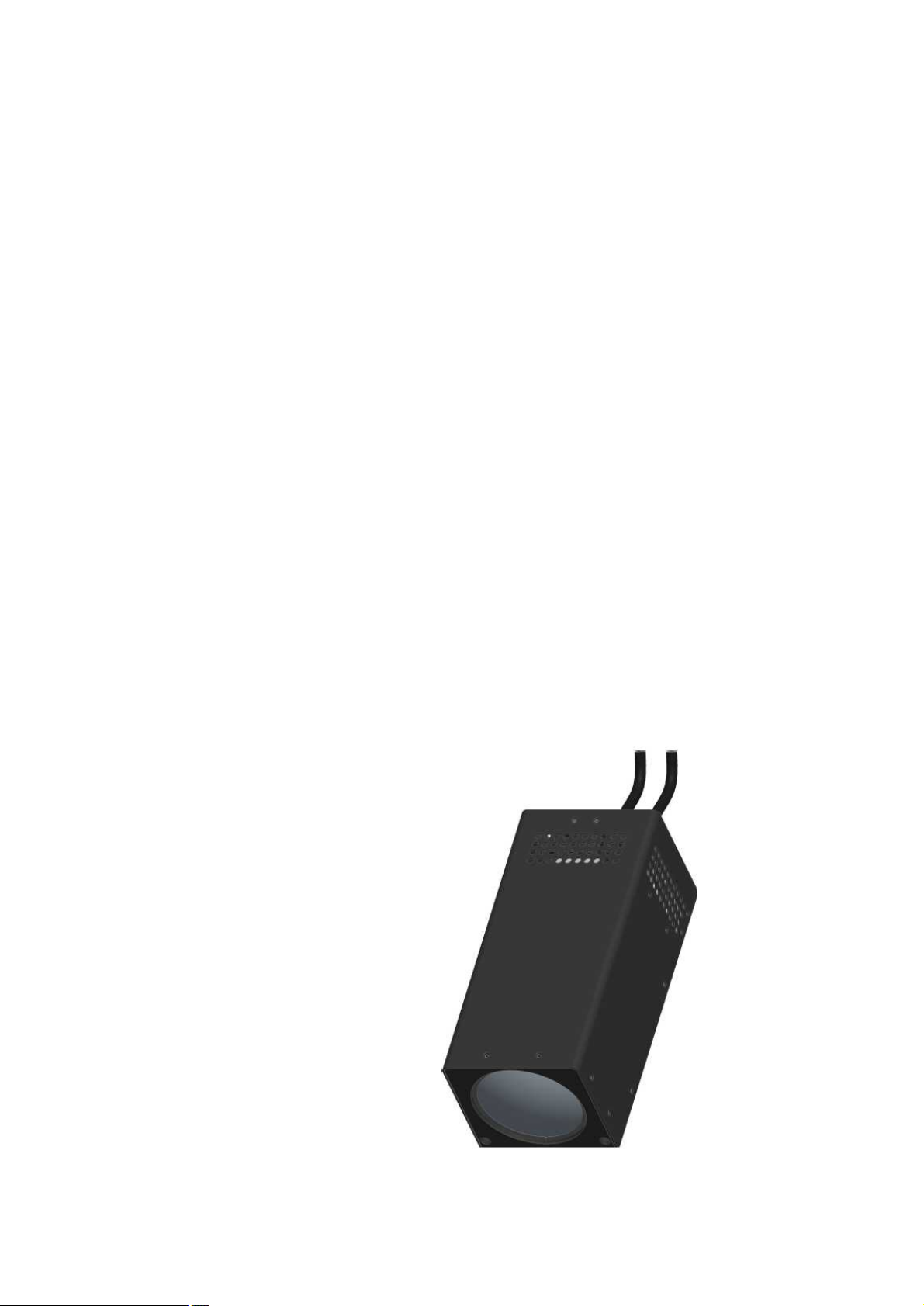
The VM series laser illuminator is high performance integrated with high quality VCSEL chip
and excellent optics design, and outstanding circuit control with high efficiency.
It has widespread angle zooming, which can match the field view angle of cameras.
User can control the beam angle by controlling a motor that enables to move the optical
lenses.
It can be widely used in high-speed dome, PTZ camera, Box camera, Military application.
Features
n Covered Distance : 1,500m
n Typical Wavelength : 860±10nm
n Fan Angle : 0.8~35°
n VCSEL Power : 6W
n Optical Output Power : 4.5W±10%
n Beam Shape : Circular
n Weight : About 1,400g
n Single Operating Voltage : DC 12V
n Protocol Interface : RS232(Default), RS485(Optional), TTL(Optional)
n Matching the Camera Angle
n High Reliability
n Long life time up to 30,000Hours
n Uniform Beam Intensity
n Speckle Free
Application
n PTZ Camera
n Box Camera
n Military Application
Page 4 / 23
Page 5

1. Profile
The laser illuminators with the model of VM-A600, is high performance and uniform beam,
it is very applicable to high definition imaging for security surveillance and factory
applications such as machine vision.
Page 5 / 23
Page 6

2. Specifications
Parameters
Typical values
Unit
Remarks
Model No.
VM-A600
Wavelength
860±10
nm
VCSEL power
6.0
W
Optical Output Power
4.5±10%
W
Beam Shape
Circular
Illuminating Distance
1,500
m
Fan Angle
0.8~35
°
±0.2°
Operating Voltage
12
V
Operating Current
2.5(Max.)
A
Operating Mode
CW
VCSEL MTTF
30,000
Hours
Operating Temperature
-30~+60
°C
Storage Temperature
-40~+70
°C
Power Consumption
30(Max.)
W
Dimension
88X82X198
mm
Housing Material
Aluminum and steel
Laser Class
4
IEC 60825-1
Protocol Interface
TTL, RS485, RS232
Weight
1,400
g
Page 6 / 23
Page 7
3. Installation and Electrical Interface
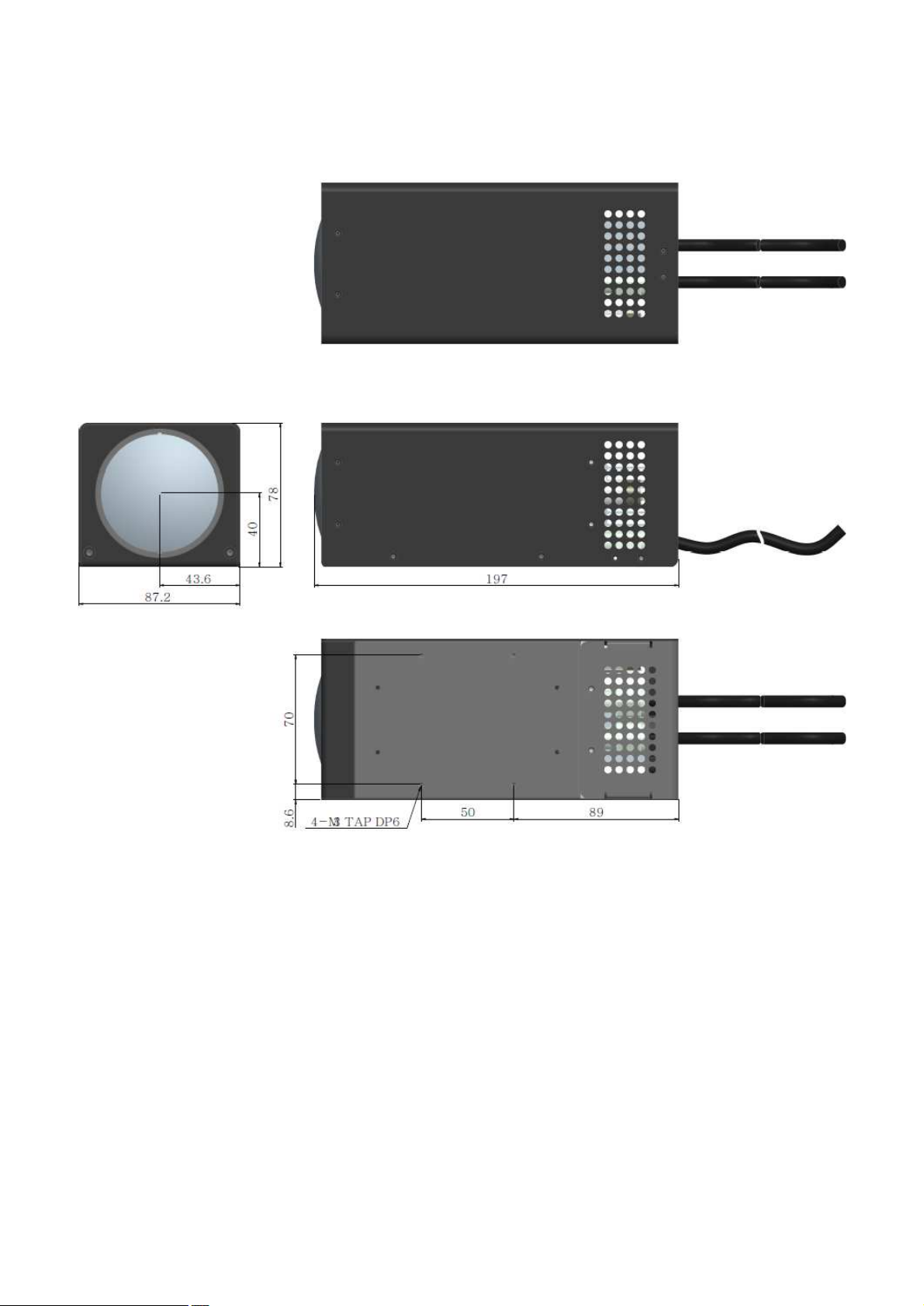
3.1 Mechanical Schematic
[Unit : mm]
Page 7 / 23
Page 8
3.2 Electrical Interface
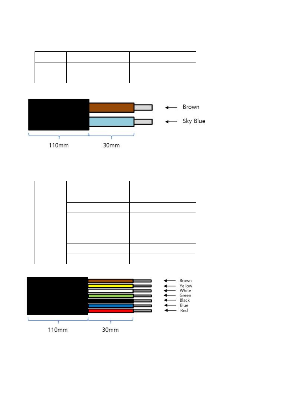
Line color
Values
Power
Brown
DC 12V
Sky Blue
GND
Line color
Values
Protocol
Interface
Brown
RS232 : TX
Yellow
RS232 : RX
White
RS485 : TRX(+)
Green
RS485 : TRX(-)
Black
GND
Blue
TTL : RXD
Red
TTL : TXD
(1) Power
- Wire Part No. : AWG18
(2) Protocol Interface
- Wire Part No. : AWG22
Page 8 / 23
Page 9
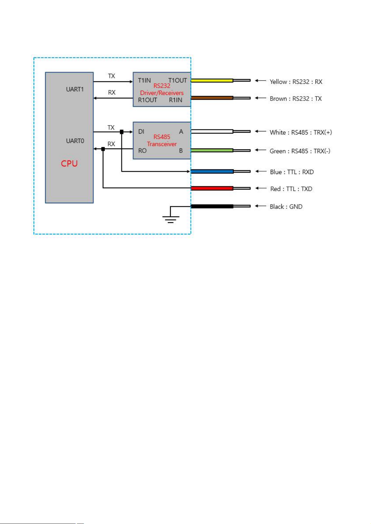
- Protocol Interface Diagram
Page 9 / 23
Page 10

4. Protocols
Byte
1 2 3 4 5
6~N
N+1
N+2
STX
SYS ID
HOST ID
CMD
SIZE
DATA
Checksum
ETX
Description
1) STX: 05h
2) SYS ID: 00h
3) HOST ID: 00h
4)SIZE: DATA SIZE
5)Checksum: 0xFF-SUM(SYS ID to DATA)
6)ETX: 06h
Byte
1 2 3 4 5
6~N
N+1
N+2
STX
HOST ID
SYS ID
CMD
SIZE
DATA
Checksum
ETX
Description
1) STX: 05h
2) SYS ID: 00h
3) HOST ID: 00h
4)SIZE: DATA SIZE
5)Checksum: 0xFF-SUM(HOST ID to DATA)
6)ETX: 06h
4.1 Protocol format
HOST -> LASER
HOST <- LASER
Page 10 / 23
Page 11

4.2 Command list
No
CMD Name
CMD No.
Response
Comment
1
SET_LASER
E0h(224d)
Yes
Laser Set Command
2
GET_LASER
E1h(225d)
Yes
Laser Get Command
3
FW_APP_UPDATE_START
90h(144d)
Yes
Firmware update command1
4
FW_BL_UPDATE_START
91h(145d)
Yes
Firmware update command2
5
FW_BL_SET_DATA
92h(146d)
Yes
Firmware update command3
6
FW_BL_UPDATE_FINISH
93h(147d)
Yes
Firmware update command4
7
8
9
10
11
12
13
14
15
16
17
18
19
20
21
22
23
24
25
26
27
28
29
30
31
32
33
34
35
Page 11 / 23
Page 12

4.3 Command
No
Function
SET_LASER
1
Remark
1) Set laser
Byte
1 2 3 4 5
6~N
N+1
N+2
STX
ID
CMD
SIZE
DATA
CS
ETX
Command
Packet
05h
SYS ID
HOST ID
E0h
TS1
TD1-TDN
CS
06h
Ack Packet
05h
HOST ID
SYS ID
E0h
RS1
RD1-RDN
CS
06h
Parameter
TS1, TD1~TDN: Please refer to the following table
RS1: Same as TS1, RD1-RDN: Same as TD1-TDN
TS1
TD1-TDN
01h
[TD1] LASER_LD_STEP_UP (01h) : Increase the output power 1 step
[TD1] LASER_LD_STEP_DOWN (02h): Decrease the output power 1 step
[TD1] LASER_LD_OUT_STOP (03h): Shut off the output power
[TD1] LASER_LD_OUT_START (04h): Start the output power
[TD1] LASER_LD_OUT_MAX (05h): Max. output power
[TD1] LASER_MOT_STEP_GO (30h): Go 25 step (Become smaller)
[TD1] LASER_MOT_STEP_BACK (31h): Back 25 step (Become bigger)
[TD1] LASER_MOT_RESET_MOVE (33h): Move to reset position
[TD1] LASER_MOT_25_STEP_GO (34h): Go 250 step(1/10)(Become smaller)
[TD1] LASER_MOT_25_STEP_BACK (35h): Back 250 step (1/10) (Become bigger)
[TD1] LASER_MOT_MID_MOVE (36h): Move to middle position
[TD1] LASER_MOT_START_MOVE (37h): Move to end position (Min. beam)
[TD1] LASER_MOT_HOME (3Bh): Move to home position of motor (Sensor detection position)
[TD1] SYS_SOFT_RESET (62h): Soft reset
02h
[TD1] LASER_LD_STEP_SEL (06h): Output any step
[TD2] LD Out Value (00h~64h)
[TD1] LASER_LD_INCREASE (07h) : Sequential increment of laser output power
[TD2] LD Increase Speed (00h ~ FFh)
[TD1] LASER_LD_DECREASE (08h): Sequential decrement of laser output power
Page 12 / 23
Page 13

[TD2] LD Decrease Speed (00h ~ FFh)
[TD1] LASER_LD_STOP (09h): Stop the sequential increment and sequential decrement of laser output power
[TD2] 0x00
[TD1] LASER_MOT_INCREASE (38h) : Sequential increment of motor step value
[TD2] MOT Increase Speed (00h ~ FFh)
[TD1] LASER_MOT_DECREASE (39h): Sequential decrement of motor step value
[TD2] MOT Decrease Speed (00h ~ FFh)
[TD1] LASER_MOT_STOP (3Ah): Stop the sequential increment and sequential decrement of motor step value
[TD2] 0x00
03h
[TD1] LASER_MOT_STEP_MOVE(32h): Move any step
[TD2] MOT Move Value (00h~FFh) Low Byte
[TD3] MOT Move Value (00h~0Fh) High Byte
04h
[TD1] LASER_MOT_STEP_MOVE(40h): Move any step (Designation motor speed)
[TD2] MOT Move Value (00h~FFh) Low Byte
[TD3] MOT Move Value (00h~0Fh) High Byte
[TD4] MOT Move Speed (00h ~ FFh)
Page 13 / 23
Page 14
No
Function
GET_LASER
2
Remark
1) Read the set value of laser
Byte
1 2 3 4 5
6~N
N+1
N+2
STX
ID
CMD
SIZE
DATA
CS
ETX
Command
Packet
05h
SYS ID
HOST ID
E1h
TS1
TD1-TDN
CS
06h
Ack Packet
05h
HOST ID
SYS ID
E1h
RS1
RD1-RDN
CS
06h
Parameter
TS1, TD1~TDN: Please refer to the following table
RS1, RD1~RDN: Please refer to the following table
Remark
TS1
TD1-TDN
01h
[TD1] LASER_MONITORING (01h): Request current set value
[TD1] LASER_FW_VERSION (02h): Request firmware version
[TD1] FAN_SENSOR_TEMP (52h): Get the sensing temperature of the fan sensor
RS1
RD1-RDN
06h
TD1= LASER_MONITORING ,
[RD1] LASER_MONITORING (01h)
[RD2] Temp Value (00h ~ FFh)
[RD3] LD Out Value (00h ~ 64h)
[RD4] MOT Move Value (00h ~ FFh) Low Byte
[RD5] MOT Move Value (00h ~ 0Fh) High Byte
[RD6] Status Value (00h ~ FFh)
03h
TD1= LASER_FW_VERSION ,
[RD1] LASER_FW_VERSION (02h)
[RD2] App Version (00h~09h) High Byte
[RD3] App Version (00h~63h) Low Byte
TD1= FAN_SENSOR_TEMP ,
[RD1] FAN_SENSOR_TEMP (52h)
[RD2] Sensor Temp (00h~FFh) Low Byte (The value of multiple by 100 for two decimal places)
[RD3] Sensor Temp (00h~FFh) High Byte (The value of multiple by 100 for two decimal places)
Page 14 / 23
Page 15
No
Function
FW_APP_UPDATE_START
3
Remark
1) Jump to bootloader command
Byte
1 2 3 4 5
6~N
N+1
N+2
STX
ID
CMD
SIZE
DATA
CS
ETX
Command
Packet
05h
SYS ID
HOST ID
90h
04h
TD1-TDN
CS
06h
Ack Packet
05h
HOST ID
SYS ID
94h
04h
RD1-RDN
CS
06h
Parameter
TD1: BaudRate and Block Size
BIT7
BIT6
BIT5
BIT4
BIT3
BIT2
BIT1
BIT0
Block Size
BaudRate
-128bytes: 20h
- Regardless of value, 9600bps
TD2-TD3: Target
- Laser: 40h
TD4: Model
- VM Series 80h
RD1: Update Status
-FW_APP_START_OK: 00h
-FW_APP_START_FAIL: 01h
-FW_BL_START_OK: 02h
-FW_BL_START_FAIL: 03h
-FW_BL_UP_DATA_OK: 04h
-FW_BL_UP_DATA__FAIL: 05h
-FW_BL_UP_DATA_REBOOT_FAIL: 06h
-FW_BL_FINISH_OK: 07h
-FW_BL_FINISH_FAIL: 08h
-FW_BL_FINISH_REBOOT_FAIL: 09h
-FW_BL_UP_DATA_TIME_OUT: 0Ah
-FW_BL_UP_CHECKSUM_ERROR: 0Bh
-FW_BL_VERIFY_DATA_OK: 0Ch
-FW_BL_VERIFY_DATA_FAIL: 0Dh
RD2: Current FW Version(VersionH)
RD3: Current FW Version(VersionL)
RD4: 00h
비고
Page 15 / 23
Page 16

No
Function
FW_BL_UPDATE_START
4
Remark
1) Erase flash command
Byte
1 2 3 4 5
6~N
N+1
N+2
STX
ID
CMD
SIZE
DATA
CS
ETX
Command
Packet
05h
SYS ID
HOST ID
91h
04h
TD1-TDN
CS
06h
Ack Packet
05h
HOST ID
SYS ID
94h
05h
RD1-RDN
CS
06h
Parameter
TD1: Currebt update target
- Laser: 07h
TD2: FW page size(File size / Block size) low byte
TD3: FW page size(File size / Block size) high byte
TD4: Model
- VM Series 80h
RD1: Update Status
-FW_APP_START_OK: 00h
-FW_APP_START_FAIL: 01h
-FW_BL_START_OK: 02h
-FW_BL_START_FAIL: 03h
-FW_BL_UP_DATA_OK: 04h
-FW_BL_UP_DATA__FAIL: 05h
-FW_BL_UP_DATA_REBOOT_FAIL: 06h
-FW_BL_FINISH_OK: 07h
-FW_BL_FINISH_FAIL: 08h
-FW_BL_FINISH_REBOOT_FAIL: 09h
-FW_BL_UP_DATA_TIME_OUT: 0Ah
-FW_BL_UP_CHECKSUM_ERROR: 0Bh
-FW_BL_VERIFY_DATA_OK: 0Ch
-FW_BL_VERIFY_DATA_FAIL: 0Dh
RD2: Currebt update target
-Laser: 07h
RD3: Current FW Version(VersionH)
RD4: Current FW Version(VersionL)
RD5: 0x00
비고
Page 16 / 23
Page 17

No
Function
SMC_FW_BL_SET_DATA
5
Remark
1) Write data to flash command
Byte
1 2 3 4 5
6~N
N+1
N+2
STX
ID
CMD
SIZE
DATA
CS
ETX
Command
Packet
05h
SYS ID
HOST ID
92h
82h(130)
TD1-TDN
CS
06h
Ack Packet
05h
HOST ID
SYS ID
94h
03h
RD1-RDN
CS
06h
Parameter
TD1: FW current page number low byte
TD2: FW current page number high byte
TD3-TD130: FW data 128bytes
RD1: Update Status
-FW_APP_START_OK: 00h
-FW_APP_START_FAIL: 01h
-FW_BL_START_OK: 02h
-FW_BL_START_FAIL: 03h
-FW_BL_UP_DATA_OK: 04h
-FW_BL_UP_DATA__FAIL: 05h
-FW_BL_UP_DATA_REBOOT_FAIL: 06h
-FW_BL_FINISH_OK: 07h
-FW_BL_FINISH_FAIL: 08h
-FW_BL_FINISH_REBOOT_FAIL: 09h
-FW_BL_UP_DATA_TIME_OUT: 0Ah
-FW_BL_UP_CHECKSUM_ERROR: 0Bh
-FW_BL_VERIFY_DATA_OK: 0Ch
-FW_BL_VERIFY_DATA_FAIL: 0Dh
RD2: FW current page number low byte
RD3: FW current page number high byte
Remark
Page 17 / 23
Page 18

No
Function
FW_BL_UPDATE_FINISH
6
Remark
1) Write data to flash command
Byte
1 2 3 4 5
6~N
N+1
N+2
STX
ID
CMD
SIZE
DATA
CS
ETX
Command
Packet
05h
SYS ID
HOST ID
93h
00h - CS
06h
Ack Packet
05h
HOST ID
SYS ID
94h
03h
RD1-RDN
CS
06h
Parameter
RD1: Update Status
-FW_APP_START_OK: 00h
-FW_APP_START_FAIL: 01h
-FW_BL_START_OK: 02h
-FW_BL_START_FAIL: 03h
-FW_BL_UP_DATA_OK: 04h
-FW_BL_UP_DATA__FAIL: 05h
-FW_BL_UP_DATA_REBOOT_FAIL: 06h
-FW_BL_FINISH_OK: 07h
-FW_BL_FINISH_FAIL: 08h
-FW_BL_FINISH_REBOOT_FAIL: 09h
-FW_BL_UP_DATA_TIME_OUT: 0Ah
-FW_BL_UP_CHECKSUM_ERROR: 0Bh
-FW_BL_VERIFY_DATA_OK: 0Ch
-FW_BL_VERIFY_DATA_FAIL: 0Dh
RD2: FFh
RD3: FFh
Remark
Page 18 / 23
Page 19
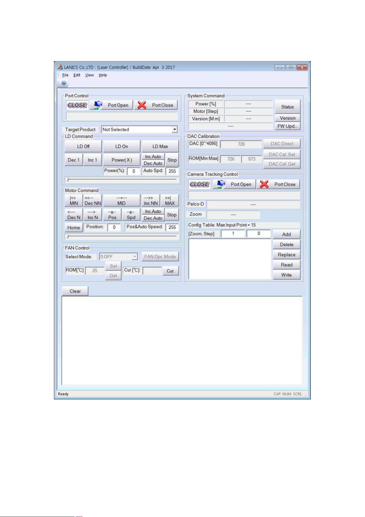
5. VM Control Program
Page 19 / 23
Page 20
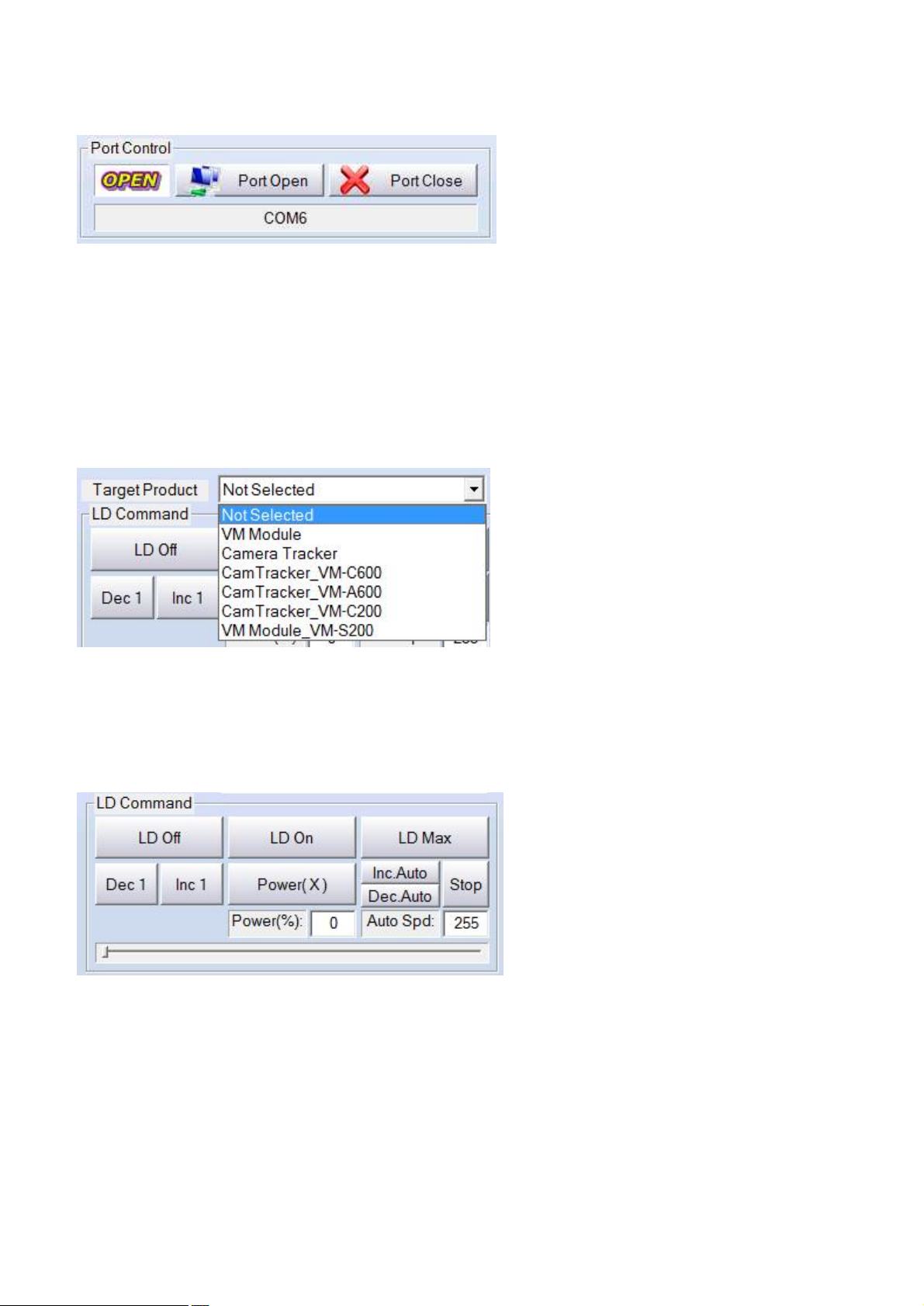
5.1 Port Control
Command group to which the communication port control
- Open: Open the communication port
- Close: Close the communication port
- Message Box: Show the port number that is currently being used
5.2 Target Product
Choose the affected product among products group
Change the range of step motor as select
5.3 LD Command
Command group to which the output power of laser diode control
- LD Off: Off the power of laser diode. Shut off automatically if the set power is 0%
- LD On: On the power of laser diode. Shut on automatically if the set power is over 1%
- LD Max: Set the maximum output power of laser diode
- Dec 1: Decrease 1% of current output power
- Inc 1: Increase 1% of current output power
- Power(X): Control any power.
The output power can be set if user input the value in the box of Power(%) or use slider control bar.
Page 20 / 23
Page 21
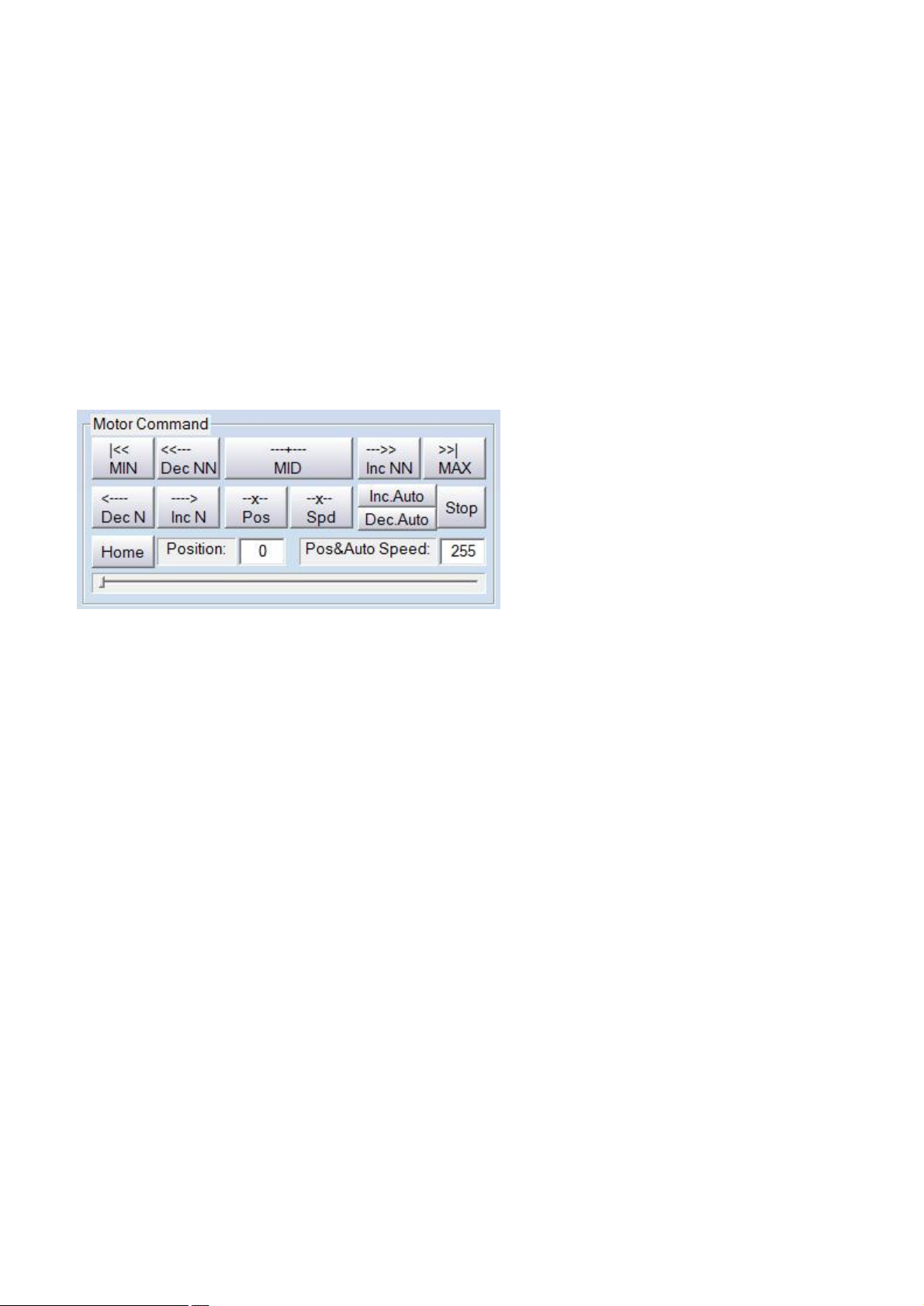
Need to click the button after input the value.
- Inc. Auto: Gradually increase the output power of laser to 100%
User can input the value from 0 to 255 user want in the box of ‘Auto Spd:
- Dec. Auto: Gradually decrease the output power of laser to 0%
User can input the value from 0 to 255 user want in the box of ‘Auto Spd:
- Stop: Stop the changing output power when the laser power are changing by command of ‘Inc. Auto’ or ‘Dec.
Auto’
5.4 Motor Command
Command group to which the beam angle control
- MIN: Move to the minimum step position
- Dec NN: Move the 250 step to minimum step position
- MID: Move to the middle step position
- Inc NN: Move the 250 step to maximum step position
- MAX: Move the maximum step position
- Dec N: Move the 25 step to minimum step position
- Inc N: Move the 25 step to maximum step position
- Pos: Move any position
User can set the step position value if user input the value in the box of Position or use slider control bar.
Control automatically the step range as the choice of target product. (ex: VM-P6000=4500, VM-
S200=3300)
- Spd: Move to any position
User can set the speed value from 0 to 255 if use input the value in the box of Pos&Auto Speed
5.5 FAN Command
Command group to which the heat sinking fan control
Page 21 / 23
Page 22
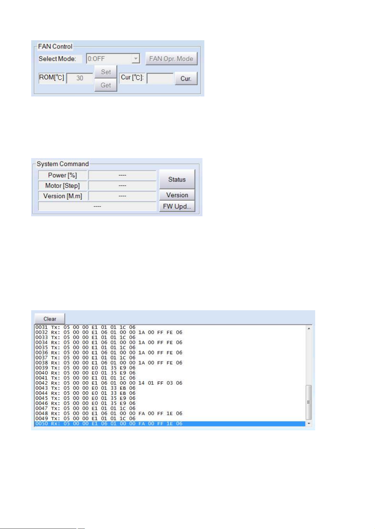
- Cur.: Show the current temperature value from the temperature sensor
(Show the value after division 100)
5.6 System Command
Command group of system
- Status: Can check the current output power and motor step value
Can also check the value when the power is changing or Motor is moving
- Version: Can check the current firmware version
- FW Upd…: The command is that new firmware update in inside flash memory.
5.7 Log Window
Window to which communication frame show
- Clear: Initialize the frame serial number after delete all displayed contents
- XXXX (4 Digit): The serial number of frame
- TX: Show the transmitted frame from window program to the illuminator
- RX: Show the transmitted frame from the illuminator to the window program
Page 22 / 23
Page 23

- Data: Show the frame information to Hexadecimal notation in bytes
Please refer to the protocol manual if you want the details
Lanics.Co.,Ltd
#703 Woolim E biz center 170-5, Guro-Dong, Guro-Gu, 152-769, Seoul, Korea
Tel. : +82-2-2108-2255 Fax. : +82-2-2108-2260
URL: http://www.lanics.com
Mail : [email protected]
Page 23 / 23
 Loading...