

JINAN LANGRUI DETECTION TECHNOLOGY CO.,LTD.
R
LR-G200 Integrated Rebar Scanner
Operating Instructions

PREFACE
Your choice of the products made by Jinan Langrui Detection Technology
Co., Ltd.(LANGRY)is greatly appreciated. We are committed to deliver you
excellent products and satisfied sales services. Please carefully read the instruc-
tions prior to use.
1. The instructions are prepared to provide the correct and complete
descriptions of related products and data. However, we do not guarantee that
there are no errors or omissions. Therefore, we will not bear responsibilities for
any resulting consequences.
2. LANGRY keeps the right of updating the instructions without prior notice.
3. LANGRY bears no responsibilities for possible losses from data deviation
or incorrect testing conclusion arising from instrument failure and other errors.
4. When the instrument is put into operation, it means that you have
carefully read and had full picture of all terms in the instructions, and you have
fully agreed to all the terms in the instructions.
5. LANGRY will not bear responsibilities for all the signed agreements violat-
ing the statement during the sales and services process not involving LANGRY.
Contents
1 Overview ......................................................................................................................1
1.1 Introduction ...............................................................................................................1
1.2 Functions and characteristics..................................................................................1
1.3 Technical indicators..................................................................................................2
1.4 Performance Indicators............................................................................................4
1.5 Precaution..................................................................................................................4
1.6 Responsibility.............................................................................................................6
2 Instrument Description.............................................................................................7
2.1 Instrument Composition..........................................................................................7
2.2 Testing Principle .......................................................................................................9
3 Operation Descriptio .................................................................................................9
3.1 System Overview .......................................................................................................9
3.2 Function description ..............................................................................................10
3.3 Firmware upgrading ...............................................................................................44
4 Maintenance and repair ..........................................................................................45
4.1 Pre-operation inspection .......................................................................................45
4.2 Cleaning ....................................................................................................................45
4.3 Battery.......................................................................................................................45
5 Precautions on field detection...............................................................................46
6 Metering and calibration.........................................................................................47
7 Data analysis software description.......................................................................49
7.1 Introduction..............................................................................................................49
7.2 Software installation...............................................................................................50
7.3 System setting ..........................................................................................................51
7.4 Receiving component data ....................................................................................52
7.5 Data processing .......................................................................................................54
7.6 Upgrading.................................................................................................................58
1 Overview
1.1 Introduction
LR-G200 integrated rebar scanner is a portable intelligent NDT device, which is
mainly used for structural testing of reinforced concrete, and able to carry out
accurate testing on depth of rebar cover and diameter of rebar on the surface of
reinforced concrete, and analyze distribution of rebar.
1.2 Functions and characteristics
1. The instrument sensor is of integrated structure in small size, thus permitting
easy operation.
2. Carry out testing with combination of high-power transmitting coil and
multiple small coil to ensure higher accuracy and resolution.
3. Perform displacement scanning and rebar distance measurement at a higher
accuracy level with use of high-accuracy grating sensor.
4. Provide different types of scanning to suit the different measurement cases.
5. Permit large and small-range testing, with the scanning distance up to 65m
max. Perform data testing in a flexible way. The instrument itself allows storage
of max. 4000 components.
6. Permit correction of multiple stirrup so as to obtain more accurate testing
results.
7. Furthermore, the USB wire data transmission and Bluetooth wireless data
1
transmission are allowed so that the quick data uploading is possible.
8. Use 3.2" 65K color LCD screen to yield the higher resolution and better display,
plus the capacitive touch screen, thus facilitating the man-machine interaction.
9. Perform power supply with use of 8.4v 3200mah high capacity lithium-ion
battery to ensure that the instrument can continuously operate around-the-clock.
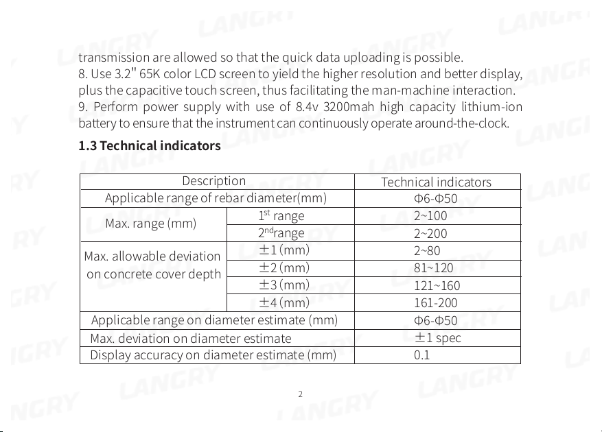
1.3 Technical indicators
Description
Applicable range of rebar diameter(mm)
st
Max. range (mm)
Max. allowable deviation
on concrete cover depth
1 range
nd
2 range
±1(mm)
±2(mm)
±3(mm)
±4(mm)
Applicable range on diameter estimate (mm)
Max. deviation on diameter estimate
Display accuracy on diameter estimate (mm)
2
Technical indicators
Φ6-Φ50
2~100
2~200
2~80
81~120
121~160
161-200
Φ6-Φ50
±1 spec
0.1
Detailed specification on testing of concrete cover depth
Dia.
Range
6
8
10
12
14
16
18
20
22
25
28
32
36
40
50
Small
2~70 2~97
2~70
2~75
2~75
2~75
3~85
3~85
3~85
3~85
3~90
3~90
4~95
4~95
4~95
6~100
3
Large
2~97
3~100
3~107
3~117
3~120
3~125
3~137
3~140
3~145
3~145
4~155
4~155
5~185
6~200
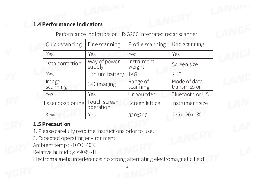
1.4 Performance Indicators
Performance indicators on LR-G200 integrated rebar scanner
Grid scanning
Yes
Screen size
3.2"
Mode of data
transmission
Instrument size
235x120x130
Quick scanning
Yes
Data correction
Yes
Image
scanning
Yes Yes
Laser positioning
3-wire
Fine scanning
Profile scanning
Yes Yes
Way of power
supply
Lithium battery
3-D imaging
Instrument
weight
1KG
Range of
scanning
Unbounded Bluetooth or US
Touch screen
operation
Yes
Screen lattice
320x240
1.5 Precaution
1. Please carefully read the instructions prior to use.
2. Expected operating environment:
Ambient temp.: -10℃~40℃
Relative humidity: <90%RH
Electromagnetic interference: no strong alternating electromagnetic field
4
Exposure to direct sunshine for an extended period prohibited
Corrosion control: take necessary measures to ensure proper operation at the
humid, dust and corrosive gas environment.
3. Expected storage environment:
Ambient temp.: -20℃~50℃
Relative humidity: <90%RH
In case of out of use for an extended period, please regularly switch on the instru-
ment and recharge it. The instrument shall be placed at a well ventilated, cool
and dry location without repeated exposure to direct sunshine.
4. Prevent moisture impact, and operation at the intense magnetic fields, such as
in the vicinity of large electrical magnet, transformer, VFD, etc.
5. Vibration control: take measures to prevent violent vibration and impact during
operation and handling.
6. Charge management: the instrument is recharged with the rechargeable
lithium battery. In case of low battery, recharge the instrument without delay to
avoid battery damage. Perform recharge with the recharger specific to the instru-
ment rather than other types of adapter or recharger, which may otherwise lead
to battery damage.
7. Maintenance: conduct proper cleaning at the end of operation every time to
prevent declined performance or property damage due to dust presence in the
5
instrument or plug connector.
1.6 Responsibility
The instrument is a precision detector. We will bear no responsibility in case of
the following user operations being identified.
1. Incompliance with the above working environment requirements or storage
environment requirements.
2. Non-standard operation.
3. Unauthorized removal of the casing and parts.
4. Serious instrument damage by operator or accident.
6
2 Instrument Description
2.1 Instrument Composition
The instrument consists of main machine, specific charger and attachment.
2.1.1 Main Machine
LR-G200 integrated rebar scanner is illustrated below.
2.1.2 External Interface
USB interface: data transmission interface is used for connection to the computer
to upload the data saved in the instrument.
Charge interface: when the instrument shows low battery, charge with the specific
recharger via the interface.
7
2.1.3 Key Description
Key
Function description
Switch on or off the instrument
Diameter estimate key or instrument
calibration
Confirm current selection
Back to the previous menu
Option up or digital adjustment up
Option down or digital adjustment down
Multi-function key
Note: Refer to the related chapters for details on function of each key.
8
2.2 Testing Principle
The instrument will generate the pulsed magnet field via high-current excitation
transmitting coil. In case of rebar being detected underneath the magnetic field,
the rebar will produce the turbulence at the excitation of pulsed magnet field, and
then make an induced magnetic field. The receiving coil will convert the induced
magnetic field to an electrical signal. The main machine performs real-time analysis
of the electrical signal, and then identify the location of rebar, concrete cover
depth and diameter. The receiving coil is configured in a multiple set of coil
combination, thus yielding the higher testing accuracy against the traditional coil
testing in a single way.
3 Operation Description
3.1 System Overview
LR-G200 Integrated rebar scanner system is designed to assure indication of each
function menu, instrument status, measurement data and result. The man-machine
interaction for the entire system is achieved through the key and touch units,
which is easier to operate than the traditional simple key operation.
3.1.1 Interface Description
The system interface mainly contains the menu selection and data result display,
in which there are title display zone and content display zone. In the title display
zone, the current interface title, Bluetooth device and USB interface readiness
9
and instrument battery status appear. In the content display zone, the main
content in the current interface appears.
3.1.2 Operation Method Description
The user can work via key or touch screen. Use of touch screen is more convenient
so we recommend to run the instrument with touch screen.
Key operation: the user can select the desired menu via Up or Down key in each
interface, and confirm with 【OK】 key. Exit or cancel with【C】 key.
Touch screen operation: the user can work with the icon in the touch screen.
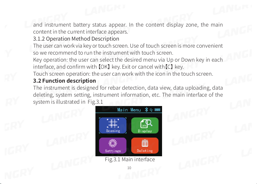
3.2 Function description
The instrument is designed for rebar detection, data view, data uploading, data
deleting, system setting, instrument information, etc. The main interface of the
system is illustrated in Fig.3.1
Fig.3.1 Main interface
10
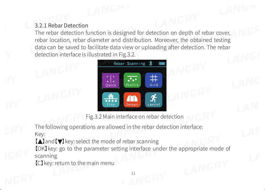
3.2.1 Rebar Detection
The rebar detection function is designed for detection on depth of rebar cover,
rebar location, rebar diameter and distribution. Moreover, the obtained testing
data can be saved to facilitate data view or uploading after detection. The rebar
detection interface is illustrated in Fig.3.2.
Fig.3.2 Main interface on rebar detection
The following operations are allowed in the rebar detection interface:
Key:
【 】and【 】key: select the mode of rebar scanning
【OK】key: go to the parameter setting interface under the appropriate mode of
scanning
【C】key: return to the main menu
11
Touch: touch the appropriate icon to go to the appropriate mode of scanning
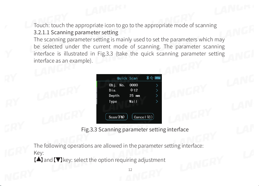
3.2.1.1 Scanning parameter setting
The scanning parameter setting is mainly used to set the parameters which may
be selected under the current mode of scanning. The parameter scanning
interface is illustrated in Fig.3.3 (take the quick scanning parameter setting
interface as an example).
Fig.3.3 Scanning parameter setting interface
The following operations are allowed in the parameter setting interface:
Key:
【 】and【 】key: select the option requiring adjustment
12
【OK】key: go to the status of change for the option
【C】key: exit the parameter change status or return to the rebar detection
interface.
【FN】key: go to detection
Touch: touch the area requiring change to complete parameter change. Touch
the appropriate icon button to function as expected.
The parameters permitting change are as follows:
Component No.
The component no. consists of digit, letter and symbol. The user can set a
component no. in max. 12 digits and min. 1 digit. The user may carry out setting
whenever required, as detailed below:
Move the cursor to the desired component no. Press 【OK】 key or directly touch
the field to go to the component no. edit status. Now, a soft keyboard will appear
in the bottom of screen. Select the character to be entered with use of direction
key, and press 【OK】key to confirm or directly touch Enter. Later, press 【C】 key or
touch the return button to exit the edit status.
Design Diameter
It is used to set the diameter of rebar being detected. Total 15 types of rebar diameter
can be selected, ie. 6, 8, 10, 12, 14, 16, 18, 20, 22, 25, 28, 32, 36, 40, 50.
You have to set the design diameter at both X and Y directions simultaneously
13
under the grid scanning and image scanning modes.
Design Depth
It is used to set the depth of design cover for the rebar being detected within a
range of 2-200.
You have to set the design depth at both X and Y directions simultaneously under
the grid scanning and image scanning modes.
Type Of Component
It is used to set the type of rebar component being detected. You may select two
types of component, i.e. “Beam” and “Slab”.
Notes:
1)The component no. can be set in max. 12 digits without space. If you start
detection without entering the component no., a prompt message will appear,
reminding you of entering the component no.
2)For rebar cover depth measurement, it is required to set the rebar diameter
beforehand. Only with correct setting of design diameter, can the correct Detailed
specification on testing of concrete cover depth being measured be assured.
Otherwise, deviation to a varying extent may occur.
3)Setting of design depth and component type parameters is a basis of assessing
if the Detailed specification on testing of concrete cover depth at the measuring
point during measurement is acceptable. All unacceptable measurements in the
14
measurement interface are highlighted in red for quick identification.
3.2.1.2 Quick scanning
In the quick scanning interface, slowly move the trolley at constant speed to the
right to start measurement. When the trolley approaches the rebar, a green
aiming box appears. Now, slowly move the trolley while the aiming box slowly
approaches the centerline. When the aiming box completely fits the centerline,
the aiming box turns out to be red and the red light gets lit, plus beep sound being
heard. The laser light in front of the instrument will emit a red line,indicating that
the instrument has detected the rebar, right below the red line. In case of
automatic storage mode being set, automatic storage is performed to assess the
concrete cover depth. In case of manual storage mode being set, press 【FN】key
to save the depth value, which appears in the bottom of screen. When the trolley
moves far from the rebar, the aiming box gets away from the centerline. When the
aiming box moves beyond the effective range of detection, the aiming box
returns back to the centerline, highlighted in grey. When the trolley stays between
two rebars, the aiming box is in blue.
Continue to move the trolley to the right for detection of next rebar. The same
hint will appear in the instrument. Now, the concrete cover depth and distance to
the previous rebar will appear simultaneously. As illustrated in Fig.3.4, the
concrete cover depth is now 11mm, concrete cover depth for the previous rebar
15
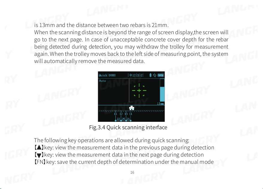
is 13mm and the distance between two rebars is 21mm.
When the scanning distance is beyond the range of screen display,the screen will
go to the next page. In case of unacceptable concrete cover depth for the rebar
being detected during detection, you may withdraw the trolley for measurement
again. When the trolley moves back to the left side of measuring point, the system
will automatically remove the measured data.
Fig.3.4 Quick scanning interface
The following key operations are allowed during quick scanning:
【 】key: view the measurement data in the previous page during detection
【 】key: view the measurement data in the next page during detection
【FN】key: save the current depth of determination under the manual mode
16

【OK】key: switch between the manual or automatic save mode
【C】key: exit the scanning interface
【�】key: keep pressing the key to estimate the diameter of rebar being scanned,
and instantaneously press for instrument self-calibration.
Touch operation: complete appropriate operation in the field corresponding to
the touch status bar.
3.2.1.3 Profile scanning
Profile scanning is a type of scanning designed to display the location of rebar
being detected, concrete cover depth, distance of neighboring rebars, measurement
diameter, etc. in the longitudinal profile distribution diagram. This type of
scanning is similar to the quick scanning. The profile scanning is illustrated in
Fig.3.5.
With use of profile scanning, slowly move the trolley to the right. When the trolley
moves above the rebar, the aiming box in the bottom right will turn out to be red,
with the same display as that for quick scanning. Refer to the related chapter for
more details. In the bottom left of the screen, the current displacement value may
appear in a real-time manner. When the rebar is being scanned, you may see the
display in the profile point in the screen, in which the concrete cover depth is
marked. The following key operations are allowed for calculation of distance of
neighboring rebars during profile scanning:
17

Fig.3.5 profile scanning interface
Key:
【 】key: view the measurement data in the previous page during detection
【 】key: view the measurement data in the next page during detection
【�】key: keep pressing the key to estimate the diameter of rebar being
scanned, and instantaneously press for instrument self-calibration.
【C】key: exit the profile scanning
Touch operation: complete appropriate operation in the field corresponding to
the touch status bar.
18

3.2.1.4 Fine scanning
The mode of fine scanning provides the real-time indication of waveform of the
rebar being detected, rebar location, concrete cover depth, center-to-center
distance of neighboring rebars, estimated diameter, etc. in the waveform
diagram. The user may also manually add or delete the measuring point of rebar
according to the waveform distribution pattern.
It is required to determine the location of rebar in a real-time manner under the
quick scanning. Thus, the quick scanning is not suitable for scanning of heavi-
ly-distributed rebar. The fine scanning is specifically designed for heavily-distrib-
uted rebar. The fine scanning interface is illustrated in Fig.3.6.
Fig.3.6 Fine scanning interface
19

In the fine scanning interface, locate the instrument on the surface of object to
be measured, and slowly move to the right to start measurement. The signal
waveform will appear in the screen, and the real-time displacement value will
appear in the bottom left of screen. The signal value starts to increase with the
instrument approaching the rebar, and the waveform curve slowly rises. When
the instrument moves far from the rebar, the waveform curve slowly lowers
down. Now, a peak may appear. The location of peak is just the location of rebar.
A white line appears at the peak, indicating that there is a rebar here. The
concrete cover depth for the rebar will appear above the peak. When a number
of rebar is detected, the instrument will automatically calculate the rebar
distance, to be displayed below the waveform.
In case of intensive distribution of rebar distance occurring during detection, the
waveform signal will get gentle, wider than the waveform signal in the single
rebar waveform diagram. Now, the instrument has to make judgment on rebar
location in combination with variation in the neighboring waveforms. Thus, the
delayed determination of rebar location may occur.
It is required to switch to the pretty heavily-distributed rebar mode in case of
need to measure the heavily-distributed rebar. In the detection interface, press
the Down key to switch to the pretty intensive rebar mode. Under the pretty
intensive rebar mode, slowly move the trolley at constant speed to assure detection
20

accuracy. Press the Down key again to return to the intensive rebar mode.
When the scanning distance is beyond the range of screen display, the instrument
will automatically conduct screen scrolling for display, and permit max. 10m
range of scanning.
The following operations are allowed in the fine scanning:
Key:
【 】key: view the measurement data in the previous page during detection
【 】key: view the measurement data in the next page during change on mode of
detection or during detection
【�】key: keep pressing the key to estimate the diameter of rebar being scanned,
and instantaneously press for instrument self-calibration.
【FN】key: keep pressing the key to go to the manual addition and deletion of
measuring point interface
【C】key: exit the fine scanning
Touch operation: keep pressing the waveform display field in the touch screen to
go to the manual addition and deletion of measuring point interface to complete
appropriate operation in the field corresponding to the touch status bar.
In case of unacceptable waveform signal or deviation in rebar determination
occurring during detection, you may withdraw to the left to erase the waveform
with determination deviation, and restart scanning. Alternatively, you may keep
21

pressing 【FN】key at the end of scanning or keep pressing the waveform display
field in the touch screen to go to the manual addition and deletion of measuring
point interface, as illustrated in Fig.3.7. Now, the user is allowed to manually add
or delete the rebar measuring point in the interface.
The following operations are allowed in the manual addition and deletion of
measuring point interface.
Key:
【 】key: instantaneously press the key to move the cursor to the location of last
signal. Keep pressing for quick move
【 】key: instantaneously press the key to move the cursor to the location of next
signal. Keep pressing for quick move
【FN】key: add or delete a rebar at current position
【C】key: exit the fine scanning
Touch:
Touch the waveform data display field to move the cursor to the location where
the rebar needs to be added or deleted. In case that rebar addition at the current
position is allowed, the rebar button in the top of screen is highlighted. Now, you
can touch the button for rebar addition. Similarly, when the button for rebar
deletion is On, touch the button for rebar deletion.
22

Fig.3.7 Manual rebar addition/deletion
measuring point interface for fine scanning
Note:
Max. 10m scanning is permitted under fine scanning.
With access to the manual addition/deletion measuring point function under fine
scanning, the instrument is not able to return to continue measurement of this
component.
Set to the intensive rebar mode in default under the fine scanning. Measurement
of most intensive rebars can be accomplished under the fine scanning. For the
pretty intensive rebar measurement, press the Down key to switch to the pretty
intensive rebar mode, in which the rebar diameter has to be correctly set.
Conduct scanning slowly at constant speed to assure accuracy of sampling data.
23

3.2.1.5 Grid scanning
Fig.3.8 Grid scanning interface
Grid scanning is a type of measurement designed to display the location of rebar
being measured, concrete cover depth and rebar distance in the grid schematic.
In the grid schematic obtained from grid scanning, the user can clearly view the
rebar distribution. The grid scanning is illustrated in Fig.3.8.
For grid detection, firstly carry out “Grid horizontal” scanning, and slowly move
the trolley to the bottom left of screen to start recording the displacement. When
the rebar is detected, plot the rebar measuring point and concrete cover depth
with use of the grid line at the appropriate location, and calculate and display the
distance of neighboring rebars. At the end of scanning the rebar in the horizontal
direction, press 【OK】 key to switch to the “Grid vertical” scanning to continue
24

detection. At the end of entire detection, press 【C】key to save data and exit the
grid detection.
The following key operations are allowed in the grid scanning:
【 】key: view the measurement data in the previous page during detection
【 】key: view the measurement data in the next page during detection
【�】key: keep pressing the key to estimate the diameter of rebar being scanned,
and instantaneously press for instrument self-calibration.
【OK】key: switch the direction of scanning
【C】key: exit the grid detection
Touch operation: complete appropriate operation in the field corresponding to
the touch status bar.
3.2.1.6 Image scanning
Image scanning is a type of measurement for comprehensive analysis following
repeated scanning horizontally and vertically in a field of given area based on
combination of fine scanning and grid scanning, which is suitable for measure-
ment of rebar in an irregular distribution.
For image scanning, the user can conduct scanning in max. 5x5 grid (or 2x2, 3x3,
4x4 grid), i.e. horizontal scanning 5 times and longitudinal scanning 5 times. The
sequential location of scanning is up to your desire. Fig.3.9 shows the location
selection interface for image scanning.
25

Fig.3.9 Image scanning location selection interface
The following operations are allowed in the image scanning location selection
interface:
Key:
【 】【 】 key: select the location to be scanned
【FN】key: go to the location scanning or cancel the scanned data for measure-
ment again
【C】key: exit the image scanning.
Touch:
Touch the location field requiring scanning for selection. Use the touch button to
complete operation.
During the single scanning measurement for image scanning, the measurement
26

results are displayed via the waveform diagram. For detailed function and operation
parameter, refer to the fine scanning chapter for more details.
At the end of all data acquisition, the user can perform data import to the
computer for data analysis, and meanwhile generate the 3D graphics to view the
rebar distribution more accurately.
Note:
An individual scanning can cover max. 1m for image scanning mode.
An individual scanning for image scanning mode is not suitable for the manual
addition/deletion rebar measuring point function.
3.2.1.7 Diameter estimation
It is able to display the estimated diameter under all scanning modes. In case of
need to estimate the rebar diameter, move the trolley to a point just above the
rebar, and keep pressing 【...】key to go to the diameter estimate function. Wait for
3sec. after measurement, and the instrument interface will display the estimated
diameter and concrete cover depth. Automatically exit 3 sec. later.
Note:
Keep the instrument location constant during diameter measurement, which
may otherwise lead to deviation of measurement result.
The diameter measurement results are displayed only, and not saved.
3.2.1.8 Signal resetting calibration
27

In case of change to the detection environment or considerable difference
between the measured depth of rebar cover and the design, it is necessary to
carry out signal resetting calibration for the instrument. Under any mode of
measurement, press【...】key to start the signal calibration function.
Note:
Instrument calibration shall be carried out to atmosphere, far from the ferromag-
netic substances. As instructed in the interface, press【OK】key to start calibration.
Exit at the end of instruct self-calibration.
The unacceptable calibration signal indicates calibration failure. Now, carry out
calibration again.
3.2.2 Data view
There are two ways of viewing the component data available in the instrument,
i.e. in graphic and list. The user can select an appropriate way of view on a
case-by-case basis. Set to the graphic data view in default.
3.2.2.1 Component list display
In the data view interface, the component list appears, as illustrated in Fig.3.10,
including:
Component list information and data statistics of designated component
The following operations are allowed in the component list display interface:
Key:
28

【 】key: move upward to select a component
【 】key: move downward to select a component
【OK】key: go to the graphic display interface containing the selected component
data
【C】key: exit the data view interface
Touch: complete operation by touching the appropriate field or button.
Fig.3.10 Data view interface
Note:
The content of component data statistics information may vary depending on the
different modes of component scanning:
Display content of quick, profile and fine scanning: scanning type, design diameter,
design depth, scanning distance, no.s of measuring point, pass rate and detection
29

time, etc.
Display content of grid scanning: scanning type, design diameter X and Y, design
depth X and Y, scanning distance X and Y, no.s of measuring point X and Y, pass
rate X and Y, and detection time, etc.
Display content of image scanning: scanning type, design diameter X and Y,
design depth X and Y, detection time, etc.
3.2.2.2 Component data graphic display
The component data graphic interface display is designed to display the current
component’s measurement data in graphics, which is easily read and under-
stood. The graphic display interface for each mode of scanning is illustrated
below. The following operations are allowed in the component data graphic
display interface:
Key:
【 】key: scroll up to view the data in the previous screen
【 】key: scroll down to view the data in the next screen
【OK】key: go to the component data list display interface
【FN】key: switch horizontally or vertically to view the data (only grid scanning
data allowed)
【C】key: exit the component data graphic view interface
Touch: complete operation by touching the appropriate button.
30

Fig.3.11 Quick scanning
Fig.3.12 Profile scanning
31

Fig.3.13 Fine scanning
Fig.3.14 Grid scanning
32

Fig.3.15 Image scanning
Note:
1. The title bar of component data graphic display interface mainly provides
information on the scanning type of the component, no. of component and
design diameter; the graphic display field provides information on location,
depth and distance of measuring point in the measurement data in graphics.
2. In the graphic display interface of image scanning component data, you will
see the summary of all measurements first, as illustrated in Fig.3.16. The user
shall press the down direction key to select the scanning location to be viewed,
and then press【OK】key to go to the graphic data view interface for selection of
scanning location.
33

Fig.3.16 Scanning location view interface with image scanning
3.2.2.3 Component data list display
The component data list display interface is designed to display the measure-
ment data for the component in the data list. The list display interface for each
mode of scanning is illustrated below.
34

Fig.3.17 Quick scanning
Fig.3.18 Profile scanning
35

Fig.3.19 Fine scanning
Fig.3.20 Grid scanning at the horizontal direction
36

Fig.3.21 Grid scanning at the vertical direction
Fig.3.22 Image scanning
The following operations are allowed in the component data list display
interface:
37

Key:
【 】key: scroll up to view the data in the previous screen
【 】key: scroll down to view the data in the next screen
【FN】key: switch horizontally or vertically to view the data (only grid scanning-
mode allowed)
【C】key: return to the component data graphic display interface
Note:
The symbols in the component data list display interface are interpreted below:
No.⸺No. of current measuring point
Hx⸺Measured depth at the current measuring point at Direction X under the
quick, profile, fine, grid and image scanning modes
Hy⸺Measured depth at the current measuring point at Direction Y under the
grid scanning mode
Sx⸺Measured displacement at the current measuring point at Direction X
under the quick, profile, fine, grid and image scanning modes
Sy⸺Measured displacement at the current measuring point at Direction Y
under the grid scanning mode
△H ⸺Difference between the depth value at current measuring point and the
design
△S ⸺Displacement variation at the current measuring point and previous one.
38

3.2.3 Data deletion
The data deletion function is designed to allow data deletion manually. With
access to the data deletion interface, the instrument will ask you if you want to
delete data or not? (Y/N). Now, press 【OK】key or the corresponding button in the
touch screen to delete data. Press 【C】key or the corresponding button in the
touch screen to cancel data deletion. The data deletion interface is illustrated in
Fig.3.23.
Fig.3.23 Data deletion confirmation interface
39

Fig.3.24 Data deletion process interface
Note:
1. Figure out if the data are uploaded to the computer prior to data deletion since
the data are not retrieved after deletion.
2. The instrument is not configured to cancel with key or touch during data
deletion.
3.2.4 Data uploading
It is advisable to upload the data to the computer on completion of data detec-
tion or with the memory nearly fully loaded. The user can upload the data via
USB or Bluetooth interface. For Bluetooth transmission, which is an extended
function, the specific mobile phone software is required to complete uploading.
The user may make choice as required. Only USB transmission is outlined below.
40

USB transmission is carried out in steps below:
1. Conduct wiring to the instrument and computer via specific USB data cable;
2. Switch on the instrument;
3. Activate the Langrui rebar scanner management software already in the
computer;
4. Click the import component data menu in the menu bar;
5. Select the component data requiring uploading, and click the upload to start
uploading the data;
6. Wait until data transmission ends.
3.2.5 System setting
The system setting menu interface is designed to provide the user with the
system setting parameter information for his/her own adjustment, including the
power saving setting, sound setting, date setting, scan setting and system
management, as illustrated in Fig.3.25.
3.2.5.1 Power saving setting
In the power saving setting, the user can set the backlight brightness, standby
time, automatic shutdown time and horizontal laser light switch. At factory
delivery, the backlight brightness is set at 50% brightness, standby time at
10min., automatic shutdown time at 25min., and horizontal laser light On. The
user may make setting himself/herself whenever required, which can be accom-
41

plished via key and touch screen.
Fig.3.25 System setting interface
3.2.5.2 Sound setting
The sound setting includes the key tone and warning tone. The key tone is the
tone from the user's key operation and the warning tone is the tone when the
rebar is detected. The user may make setting himself/herself whenever required,
which can be accomplished via key and touch screen.
3.2.5.3 Date setting
Set the system time, including the year, month, day, hour and minute, which can
be accomplished via key and touch screen.
3.2.5.4 Scan setting
42

The scan setting menu covers the stirrup distance, range selection and rebar type.
Stirrup distance: during field detection, it is necessary to pre-scan the stirrup
distance. In case of less than 120mm, set the parameter at [100], [80], [60] and [40]
on a case-by-case basis. Now, the instrument will undergo the appropriate
compensation correction. In case of stirrup distance above 120mm, set the
parameter at [>120].
Range selection: select the small range for the small depth of rebar cover being
measured. Otherwise, switch to the large range mode. Make selection on a
case-by-case basis.
Rebar type: it includes the deformed bar and round steel.Make the appropriate
setting based on the type of rebar being detected. Ensure correct setting on rebar
type prior to detection, which may otherwise affect the measurement accuracy.
3.2.5.5 System management
Bluetooth-based uploading: instrument's extended function, to be used with the
specific mobile phone software.
Language selection: select the different operation language depending on the
user's need.
3.2.6 About device
The About device menu provides the information on the device, as illustrated in
Fig.3.26, including the following:
43

Instrument type and name
Firmware version no.
Device no.
Company contact tel.
Company website
Fig.3.26 About device interface
3.3 Firmware upgrading
There is a built-in firmware online upgrading program so that the user can carry
out firmware upgrading through connection to the computer via data cable.
Through connection to the computer via data cable, the computer software can
automatically detect the firmware version no. In case of latest version of
firmware, the computer software may ask the user if upgrading is required. Refer
44

to the software description profile for details.
Note:
You shall not shut down the instrument during firmware upgrading. If upgrading
fails, shut down the instrument and manually go to the upgrading interface for
upgrading again.
4 Maintenance and repair
4.1 Pre-operation inspection
Switch on the instrument and go to any mode of scanning for instrument self-cal-
ibration. Later, carry out scanning in the calibrated unit to check for correct
signal.
4.2 Cleaning
The instrument has no water resistance function. Cleaning with wet rag is prohibited.
Cleaning the instrument and accessories with the organic solvent is prohibited.
Clean the instrument and accessories with the clean and soft dust-free rag.
4.3 Battery
The instrument is charged with the chargeable lithium battery. The instrument
can operate for continuously 24h when it is fully charged. In case of low battery, it
will provide a warning on low battery and automatically goes to shutdown. Now,
the instrument has to be charged. In order to ensure that the instrument is fully
charged, please keep charging for 6-8h.
45

Note:
Charging at high temperature is prohibited. In case of out of use for an extended
period, the battery may have slight power loss, leading to reduced power.
Recharge prior to use. It is acceptable that the charger may be hot during
charging. Keep the charging environment well ventilated to facilitate heat
dissipation. Carry out charging with the specific charger. Use of other types of
charger or adaptor may damage the instrument.
5 Precautions on field detection
1. The rough or uneven detection surface may affect the detection accuracy.
Thus, keep the scanning surface flat without large protrusion. If the surface is too
rough to be cleaned, place a sheet on the scanning surface. The depth of the
sheet shall be deducted from the measurement result;
2. Keep the instrument to slowly move at constant speed during scanning;
3. Set the instrument to scan in a direction perpendicular to the rebar routing
direction. Otherwise, it may lead to misjudgment or deviation in depth measure-
ment;
4. For mesh rebar, typically locate the rebar at the top, and then carry out
measurement between two rebars at the top to locate the rebar in the base;
5. In case of change to the detection environment or considerable deviation in
measurement result, carry out resetting calibration on instrument signal. It is
46

recommended to carry out resetting calibration on instrument signal before
every measurement. During resetting calibration, keep away from the ferromag-
netic materials for calibration to atmosphere to ensure calibration accuracy;
6. The instrument is configured to allow large and small range switchover. There
is a higher measurement accuracy for small range case, so it is recommended to
use the small range for detection provided the conditions on range of measure-
ment are met;
7. The design diameter in the measurement parameter setting must be correctly
entered. Otherwise, deviation may occur on depth judgment.
6 Metering and calibration
The instrument will be calibrated according to the national calibration criteria
before factory delivery. The calibration content and procedure are outlined
below:
1)Calibration environment: room temperature, free of strong magnetic interfer-
ence, air relative humidity of less than 80%.
2)Calibration device: 3 rebar calibration coupons, separately standing for the
deformed bar of Φ12, Φ16 and Φ25.
3)Calibration content and detection method:
Depth: For the deformed bar in 3 sizes, the calibrated depth varies. For the Φ12
rebar, depth up to 40mm shall be detected.For the Φ25 rebar, depth above 60mm
47

shall be detected.
Carry out detection with the large and small ranges, and take 3-5 key sampling
points for continuous measurement and take note of results.
The detection results shall be acceptable to the requirements in 1.3 Performance
indicator.
Diameter: make measurement on diameter of deformed bar in 3 sizes in the
coupon. Make measurement on the deformed bar of each size 3 times and figure
out the average value. The detection results shall be acceptable to the require-
ments in 1.3 Performance indicator.
Diameter: make measurement on diameter of deformed bar in 3 sizes in the
coupon. Make measurement on the deformed bar of each size 3 times and figure
out the average value. The detection results shall be acceptable to the require-
ments in 1.3 Performance indicator.
48

7 Data analysis software description
7.1 Introduction
The rebar detection data analysis software is a multi-function analysis software
developed by Jinan Langrui Detection Technology Co., Ltd. for processing the
rebar detection data. The software can run in XP/win7/win10 OS, presenting
friendly interface and easy operation, which is specifically designed for project
detection staff.
1)Conduct management on all component information as well as the detection
data at each measuring point;
2)Conduct analysis and evaluation on detection data according to the construc-
tion quality acceptance criteria;
3)Display the component data in a graphic way;
4)Generate a detection data file through integration of several ones; it is easy to
add or remove the detection data;
5)Print the preview and export treatment results;
6)It is easy to import the rebar scanner data into the computer with use of the
software to facilitate further analysis and archive;
7)Automatically generate the detection report in word format.
The data files saved in the software has the file extension name in . xgjy format.
The detection report automatically generated has the file extension name in
49

.docx format.
7.2 Software installation
7.2.1 Installation of port driver
LR-G200 rebar scanner is furnished with the program U-disc. Please attach the
U-disc to the available USB port in the computer prior to operation. Activate the
U-disc and find out the port driver folder and open it. Double click the installation
program “setup” dialog box and then click “INSTALL”.
Start installation. Later, the “Driver pre-installation success” may appear in the
screen and click Ok. Next, attach the computer USB communication port to the
rebar scanner USB port via communication cable. Switch on the rebar scanner,
and the computer will show that the new hardware has been located. Several
minutes later, you may start operation on completion of hardware identification.
If you are asked to confirm the authorized selection, please select “Ok” and
confirm.
7.2.2 Software installation
The rebar scanner is furnished with the program U-disc. Please attach the U-disc
to the available USB port in the computer prior to operation. Activate the U-disc
and find out the “Rebar scanner online system” folder and open it. Double click
the installation program “setup-x.x” and open the installation wizard. Please
complete installation as instructed and operate it.
50

★ Please tick the option to generate a desktop shortcut. Then, you can run the
software by double clicking the desktop shortcut.
7.3 System setting
7.3.1 Enterprise information
Click “Tool (T) → Enterprise information” menu item so that the enterprise,
information option card may appear below. The enterprise information as shown
below may appropriately appear at the corresponding page location in the
testing report.
51

7.3.2 Report setting
Click “Tool (T) → Report setting” so that the following dialog box appears, showing
the print report title and print report options. A set of proposed report template
has been provided in the software for user's use. The template may be customized
to meet the user's special requirements.
7.4 Receiving component data
7.4.1 Connection to the rebar scanner host computer
1)Wiring of communication cable: confirm that the USB communication cable
leading the computer to the rebar scanner host computer has been attached.
2)Instrument power-on: press the power-on key to switch on the rebar scanner
host computer, and keep it online.
3)Click the title bar “Rebar scanner”option. Select the“Import detection data”
option in the pull-down menu, and click it. The rebar scanner data dialog box
52

appears. The software provides the automatic port identification function. If the
rebar scanner host computer is correctly attached to the computer, and main-
tained online, the software can automatically identify the communication port
and Baud rate, and display it. If the software fails to identify the communication
port or the communication port is incorrect, please click the“Refresh”in the
dialog box.
7.4.2 Data uploading
Select to import all components or partial components as illustrated above.
Then, click “Import” so that the instrument can automatically upload the select-
ed component data. No operation is required during uploading.
★When the data are transmitted the computer, the data saved in the instrument
will not get lost.
53

★You may click Cancel to stop uploading at any time during uploading.
7.5 Data processing
7.5.1 Original data processing
In the software's home page, fill out the detection information and enterprise
information, and then automatically generate a “Detection report” and “Original
data record”, which can be separately printed. In the “Detection data” master
window, you can alter all the parameters which were not correctly entered, and
make calculations again to meet the need of different clients.
54

When the data are uploaded, select the component no. in the left navigation bar,
and fill out and set the component information in the right item box. Further-
more, you can view the detection results on the component.
Grid scanning and image scanning can display 3D stereogram and plan in the
right graphic display box.
55

Display the waveform schematic via fine scanning
56

7.5.2 Report generation
Click the title bar “Data processing (D)” → Generate report to generate a report. A
report no. (for example, Report 001) may appear in the “Detection report” bar in
the left navigation bar. Click the “Report 001” to display the report fillout
interface. In the right report composition option, select the report type and tick in
the square box before the data in the bottom the data requiring report generation.
After completing the report, you may select print preview to print the report.
★In the print pre-view, click “Export word” to save the pre-viewed report in word
format.
57

7.5.3 Data deletion
If you want to delete a component, click selection and press “Data processing (D)
”→“ Delete component” to delete the selected component.
★The deleted component goes to the list of deleted components, in which you
may select the component deleted by mistake and retrieve it.
7.5.4 Data save
The original data or completed report can be saved in the computer. Click the
title bar “File (F)” →“ Save” to save the file in a format of .xgjy.
7.6 Upgrading
The user can manually carry out software upgrading and firmware upgrading.
The computer shall be attached to the internet.
Software upgrading: click the title bar “Help” →“ Check new version” so that the
software will automatically check for latest version of software. If so, the comput-
er may ask the user if upgrading is required. Click “Upgrade” to start automatic
upgrading.
Firmware upgrading: attach the rebar scanner to the computer’s USB port via
data cable. Switch on the rebar scanner, and click the software title bar “Rebar
scanner” →“ Upgrade the rebar scanner” so that the software may automatically
check for latest version of firmware software. If so, the computer may ask the user
if upgrading is required. Click “Upgrade” to start automatic upgrading
58

Components
1.LR-G200 Integrated rebar scanner
2. U-disk memory
3.Charger
4.Communication data line
5.Instrument box
6.Instrument package
7.Operating instructions
8.Product certificate
59

1 2 3
4
7 8
5 6
60

Manufacturer warranty
LANGRY guarantees that the tool is free from defects in materials and manufac-
turing processes when it leaves the factory, and the warranty is valid only if the
user correctly installs, operates, maintains and cleans the tool in accordance with
Langry's operating instructions.
The warranty covers the free replacement or repair of damaged parts during the
whole service life of this tool. If the parts need to be repaired or protected due to
normal wear and tear, they are not covered by the warranty.
Other claims are not covered by the warranty unless there is a different provision
under the specific law of the customer's country. In particular, langry shall not be
liable for any direct, indirect, incidental or inevitable damage, financial loss or
additional expenses caused by or related to the improper use or abuse of this
tool. Expressly exclude implied warranties of merchantability and fitness for a
particular purpose.
In case of repair or replacement, the tool or relevant parts shall be sent to
Langry's market organization immediately after the failure is determined.
61

JINAN LANGRUI DETECTION TECHNOLOGY CO.,LTD.
Email:langry@jnlrkj.com
Website:www.langry.cn
 Loading...