

Page 1
Installation, Operation, Maintenance, & Troubleshooting
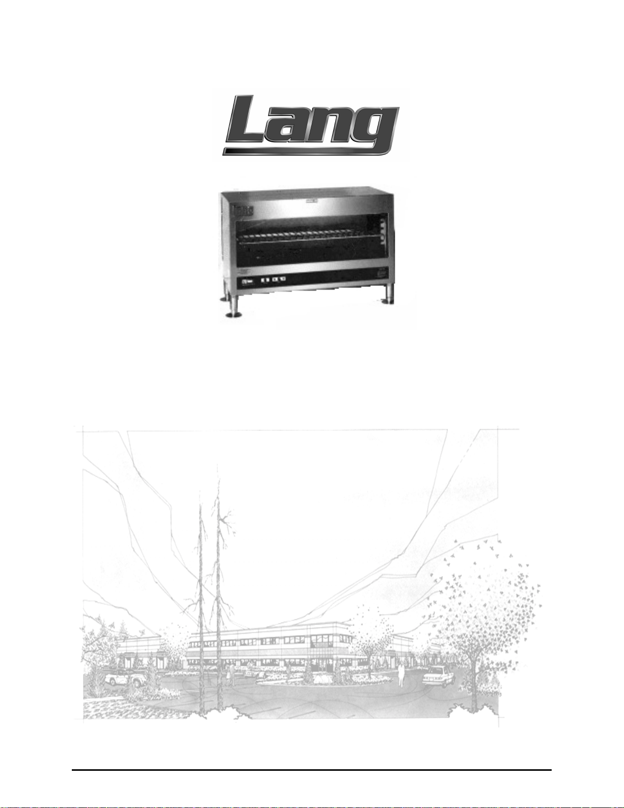
Model: MM36W-E-CLS
Serial:
Electric Cruise Line Cheese-melter
Lang Manufacturing Company 6500 Merrill Creek Parkway Everett, WA 98203
Phone: 425-349-2400 Fax: 425-349-2733
WWW.LANGWORLD.COM © Copyright 2000
Page 2

THIS MANUAL MUST BE RETAINED FOR FUTURE REFERENCE.
READ, UNDERSTAND AND FOLLOW THE INSTRUCTIONS AND
WARNINGS CONTAINED IN THIS MANUAL.
FOR YOUR SAFETY
DO NOT STORE OR USE GASOLINE OR OTHER FLAMMABLE
VAPORS AND LIQUIDS IN THE VICINITY OF THIS OR ANY
OTHER APPLIANCE.
WARNING: IMPROPER INSTALLATION, ADJUSTMENT,
ALTERATION, SERVICE OR MAINTENANCE CAN CAUSE
PROPERTY DAMAGE, INJURY OR DEATH. READ THE
INSTALLATION, OPERATING AND MAINTENANCE
INSTRUCTIONS THOROUGHLY BEFORE INSTALLING OR
SERVICING THIS EQUIPMENT.
NOTICE:
THIS EQUIPMENT IS APPROVED FOR INSTALLATION ONLY ON
VESSELS GREATER THAN 65 FEET IN LENGTH, IN
ACCORDANCE WITH USCG REGULATIONS IN TITLE 46 CFR
110-113. ANY WIRING USED IN THE INSTALLATION OF THIS
APPLAINCE MUST BE STRANDED COPPER.
2
Page 3

TABLE OF CONTENTS
CHAPTER PAGE
1. TABLE OF CONTENTS................................................................................3
2. READ FIRST..................................................................................................4
3. UNPACKING.................................................................................................6
4. INSTALLATION............................................................................................7
5. OPERATION..................................................................................................9
6. CLEANING & MAINTENANCE PROCEDURES......................................10
7. TROUBLESHOOTING..................................................................................11
8. PARTS LISTS.................................................................................................13
9. EXPLODED VIEW........................................................................................14
10. WIRING DIAGRAM......................................................................................19
11. WARRANTY..................................................................................................20
3
Page 4
IMPORTANT READ FIRST IMPORTANT
CAUTION:
CAUTION:
CAUTION:
DANGER:
WARNING:
CHEESE-MELTER WEIGHS 135 lbs (61.24 kg). FOR
SAFE HANDLING, INSTALLER SHOULD OBTAIN
HELP AS NEEDED, OR EMPLOY APPROPR IATE
MATERIALS HANDLING EQUIPMENT (SUCH AS A
FORKLIFT, DOLLY, OR PALLET JACK) TO REMOVE
THE UNIT FROM THE SKID AND MOVE IT TO THE
PLACE OF INSTALLATION.
ANY STAND, COUNTER OR OTHER DEVICE ON
WHICH THE CHEESE-MELTER WILL BE LOCATED
MUST BE DESIGNED TO SUPPORT THE WEIGHT OF
THE UNIT.
SHIPPING STRAPS ARE UNDER TENSION AND CAN
SNAP BACK WHEN CUT.
THIS APPLIANCE MUST BE GROUNDED AT THE
TERMINAL PROVIDED. FAILURE TO GROUND THE
APPLIANCE COULD RESULT IN ELECTROCUTION
AND DEATH.
INSTALLATION OF THE UNIT MUST BE DONE BY
PERSONNEL QUALIFIED TO WORK WITH
ELECTRICITY. IMPROPER INSTALLATION CAN
CAUSE INJURY TO PERSONNEL AND/OR DAMAGE
TO EQUIPMENT. UNIT MUST BE INSTALLED IN
ACCORDANCE WITH ALL APPLICABLE CODES.
NOTICE:
NOTICE:
CAUTION:
CAUTION:
The data plate is located on the left side of the unit in
the lower front corner. The voltage, wattage, serial
number, wire size, and clearance specifications are
on the data plate. This information should be
carefully read and understood before proceeding
with the installation.
The installation of any components such as a vent
hood, grease extractors, fire extinguisher systems,
must conform to their applicable National, State and
locally recognized installation standards.
ALWAYS KEEP THE AREA NEAR THE APPLIANCE
FREE FROM COMBUSTIBLE MATERIALS.
KEEP FLOOR IN FRONT OF EQUIPMENT CLEAN
AND DRY. IF SPILLS OCCUR, CLEAN IMMEDIATELY,
TO AVOID THE DANGER OF SLIPS OR FALLS.
4
Page 5
IMPORTANT READ FIRST IMPORTANT
WARNING:
CAUTION:
NOTICE:
WARNING:
CAUTION:
KEEP WATER AND SOLUTIONS OUT OF CONTROLS.
NEVER SPRAY OR HOSE CONTROL CONSOLE,
ELECTRICAL CONNECTIONS, ETC.
MOST CLEANERS ARE HARMFUL TO THE SKIN, EYES,
MUCOUS MEMBRANES AND CLOTHING.
PRECAUTIONS SHOULD BE TAKEN TO WEAR RUBBER
GLOVES, GOGGLES OR FACE SHIELD AND
PROTECTIVE CLOTHING. CAREFULLY READ THE
WARNING AND FOLLOW THE DIRECTIONS ON THE
LABEL OF THE CLEANER TO BE USED.
Service on this, or any other, LANG appliance must be
performed by qualified personnel only. Consult your
authorized service station directory or call the factory at
1-800-224-LANG (5264), or
for the service station nearest you.
BOTH HIGH AND LOW VOLTAGES ARE PRESENT
INSIDE THIS APPLIANCE WHEN THE UNIT IS
PLUGGED/WIRED INTO A LIVE RECEPTACLE. BEFORE
REPLACING ANY PARTS, DISCONNECT THE UNIT
FROM THE ELECTRIC POWER SUPPLY.
USE OF ANY REPLACEMENT PARTS OTHER THAN
THOSE SUPPLIED BY LANG OR THEIR AUTHORIZED
DISTRIBUTORS CAN CAUSE BODILY INJURY TO THE
OPERATOR AND DAMAGE TO THE EQUIPMENT AND
WILL VOID ALL WARRANTIES.
WWW.LANGWORLD.COM
5
Page 6
3.1 Receiving the Cheese-melter
Upon receipt, check for freight damage, both visible and concealed. Visible
damage should be noted on the freight bill at the time of delivery and signed by the
carrier's agent. Concealed loss or damage means loss or damage, which does not
become apparent until the merchandise has been unpacked. If concealed loss or
damage is discovered upon unpacking, make a written request for inspection by the
carrier's agent within 15 days of delivery. All packing material should be kept for
inspection. Do not return damaged merchandise to Lang Manufacturing Company.
File your claim with the carrier.
3.2 Location
Prior to un-crating, move the cheese-melter as near its intended location as
practical. The crating will help protect the unit from the physical damage normally
associated with moving it through hallways and doorways.
3.3 Un-crating
The cheese-melter will arrive completely assembled inside a wood frame covered
by cardboard box and strapped to a skid.
straps and remove the wood frame.
Remove the cardboard cover, cut the
UNPACKING
The unit back is not attached to the machine. It is packaged loose behind the
Cheese-melter.
The screws used to attach the back to the cheese-melter are screwed into the rear
edge of the machine.
CAUTION:
CAUTION:
CAUTION:
Remove cheese-melter from skid and place in intended location.
CHEESE-MELTER WEIGHS 135 lbs (61.24 kg). FOR
SAFE HANDLING, INSTALLER SHOULD OBTAIN HELP
AS NEEDED, OR EMPLOY APPROPRIATE MATERIALS
HANDLING EQUIPMENT (SUCH AS A FORKLIFT,
DOLLY, OR PALLET JACK) TO REMOVE THE UNIT
FROM THE SKID AND MOVE IT TO THE PLACE OF
INSTALLATION.
ANY STAND, COUNTER OR OTHER DEVICE ON WHICH
CHEESE-MELTER WILL BE LOCATED MUST BE
DESIGNED TO SUPPORT THE WEIGHT OF THE UNIT.
SHIPPING STRAPS ARE UNDER TENSION AND CAN
SNAP BACK WHEN CUT.
6
Page 7

INSTALLATION
DANGER:
WARNING:
NOTICE:
NOTICE:
THIS APPLIANCE MUST BE GROUNDED AT THE
TERMINAL PROVIDED. FAILURE TO GROUND THE
APPLIANCE COULD RESULT IN ELECTROCUTION AND
DEATH.
INSTALLATION OF THE UNIT MUST BE DONE BY
PERSONNEL QUALIFIED TO WORK WITH ELECTRICITY.
IMPROPER INSTALLATION CAN CAUSE INJURY TO
PERSONNEL AND/OR DAMAGE TO EQUIPMENT. UNIT
MUST BE INSTALLED IN ACCORDANCE WITH ALL
APPLICABLE CODES.
The data plate is located on the left side of the unit in the
lower front corner. The voltage, wattage, serial number,
wire size, and clearance specifications are on the data
plate. This information should be carefully read and
understood before proceeding with the installation
The installation of any components such as a vent hood,
grease extractors, fire extinguisher systems, must conform
to their applicable National, State and locally recognized
installation standards.
4.1 Assembly
The unit back is not attached to the machine. It is package loose behind the cheesemelter.
The screws used to attached the back to the cheese-melter are screwed into the rear
edge of the machine.
IF HANGING THE UNIT ON A WALL:
Split the back into two pieces; note the pre-drilled holes in one panel. This is
the wall mounting bracket.
Fasten the wall mounting bracket to the wall using pre-drilled holes. Use
suitable lag screws or anchor fasteners to secure panel to the wall with the offset at the top. Make certain that the mounting bracket is level.
Remove the screws from the rear of the cheese-melter; screw the stainless steel
portion of the back to the cheese-melter with the off-set at the top.
Lift the cheese-melter and hang it on the wall mounted bracket.
Replace the screws around the edge of the back.
Observe minimum clearances at all times.
IF HANGING THE UNIT OVER A COOKING SURFACE:
Follow instructions for hanging on a wall.
Must be mounted with 12 to 22 inches above the cooking surface.
Install the Heat Shield on the bottom of the unit.
This unit cannot be mounted above a broiler.
7
Page 8

INSTALLATION CONT’D
4.1 Electrical Connection
Electrical service routing may be made through either of two 1 1/4 inch knockouts
provided. One may be found along the bottom edge of the back panel. The second
knockout is located on the bottom of the unit.
4.2 Cheese-melter Voltage
The model MM36C-3-CLS Cheese-melter is shipped from the factory wired for 220
volts.
4.3 Phasing
All cheese-melters are shipped from the factory set up for a
4.4 Elements
Elements for all electric Cheese-melters are shipped, packaged separately, within the
shipping crate.
These should be inspected upon opening of the shipping carton. If an element is found
damaged or broken, notify the Freight Company immediately.
Installation of the elements is not a warrantable expense. The installer or a qualified
service company should complete installation. Damage to elements or equipment
resulting from incorrect or improper installation will be the responsibility of the
equipment owner or individual installing elements.
single phase
service.
WARNING:
DUE TO THE HIGH HEAT EXPOSURE EXPERIENCED AT
CONNECTIONS, USE OF NON-CERAMIC WIRE NUTS IS NOT
RECOMMENDED. DAMAGE TO EQUIPMENT, OR INJURY TO
PERSONNEL MAY RESULT.
CHEESE-MELTER SPECIFICATIONS
NOMINAL AMPS PER LINE
MODEL
NUMBER
MM36W-E-CLS
TOTAL
kW
3.6 15 135 lbs.
SINGLE PHASE
220 VOLT
WEIGHT
8
Page 9

OPERATION
CAUTION:
CAUTION:
ALWAYS KEEP THE AREA NEAR THE APPLIANCE
FREE FROM COMBUSTIBLE MATERIALS.
KEEP FLOOR IN FRONT OF EQUIPMENT CLEAN AND
DRY. IF SPILLS OCCUR, CLEAN IMMEDIATELY, TO
AVOID THE DANGER OF SLIPS OR FALLS.
6.1 General
The Lang Electric Cheese-melter can be used to poach, sauté and brown. In addition
to melting cheese on sandwiches, French onion soup, hot apple pie and casseroles, it
may be used for finishing Italian, Mexican and au gratin dishes utilizing less energy
than conventional broilers.
The product is heated with infrared energy provided by quartz heaters. Although
the heating elements are not directly controlled to regulate heat, the exposure of the
product to heat is adjustable. Heat adjustment may be obtained by raising and
lowering the rack position. The shelf positions provide a choice of cooking positions
for a variety of applications. The top position is very hot, and can be used for quick
browning and toasting, with the heat decreasing at each lower position.
In order to change positions, simply slide the rack in and out of the slots provided.
6.2 Operation
Controls are located on the front panel and consist of the following items:
Power Switch
- a toggle switch used to turn the unit on and off.
OPERATING DO's and DON'Ts
DO:
Insure all dishes placed in the cheese-melter are oven safe.
Pre-heat pans in the cheese-melter or on a stove.
Turn products halfway through cooking, as needed.
DON'T:
Do not use the cheese-melter as a cooking or baking device, it is best suited for
finishing dishes immediately pr ior to serving.
Do not use the unit to heat or thaw chilled or frozen product.
Do not place aluminum foil on the rack or bottom shelf. This will reflect heat
and expose components to unnecessary high temperatures.
Do not move rack from one position to another without hand protection.
9
Page 10

CLEANING & MAINTENANCE
WARNING: KEEP WATER AND SOLUTIONS OUT OF CONTROLS.
NEVER SPRAY OR HOSE CONTROL CONSOLE,
ELECTRICAL CONNECTIONS, ETC.
CAUTION:
MOST CLEANERS ARE HARMFUL TO THE SKIN,
EYES, MUCOUS MEMBRANES AND CLOTHING.
PRECAUTIONS SHOULD BE TAKEN TO WEAR
RUBBER GLOVES, GOGGLES OR FACE SHIELD AND
PROTECTIVE CLOTHING. CAREFULLY READ THE
WARNING AND FOLLOW THE DIRECTIONS ON THE
LABEL OF THE CLEANER TO BE USED.
7.1 Daily Cleaning (after each meal)
Always start with a cold unit.
The stainless interiors can easily be cleaned using a non-etching solution.
Follow the manufacturer's instructions when using any cleaner.
Care should be taken to prevent caustic cleaning compounds from coming in
contact with aluminized steel.
To clean the rack, remove it from the unit and soak it in a solution of ammonia and
water.
The stainless front should normally be cleaned with a soap and water solution.
Discoloration or heat tint may be removed with any of the following cleaners:
Penny Bright Copper Bright Du-Bois Temp, or Past Nu-Steel.
Always apply these cleaners when the unit is cold and rub in the direction of the
metal's grain.
CAUTION:
Never spray liquids on the quartz elements as this can
weaken the element and break the glass.
7.2 Maintenance
ELEMENT REPLACEMENT
Quartz Elements are replaced as follows:
De-energize unit and open power supply breaker.
Remove rack and set to one side.
Remove three (3) screws from each element bracket. Brackets support each end of
the elements. One or both brackets may be removed.
Remove ceramic wire nuts from both ends of the element, label wires as necessary
to allow ease of reconnection.
To check each element, use an ohmmeter and check for continuity from one end of
the element to the other. If an element is found without continuity
this element.
Hold elements in position and connect wires as they were removed. Use new
"Ceramic"
Re-install bracket supporting element ends.
wire nuts to reconnect elements.
10
(open)
, replace
Page 11

TROUBLESHOOTING
9.1 Symptoms
What follows is a chart of Symptoms and Possible Causes to aid in diagnosing
faults with the oven.
Refer to the Symptoms column to locate the type of failure then to the Possible
Cause for the items to be checked.
To test for a possible cause, refer to the TEST section and locate the Possible Cause
then refer to test to identify test procedures.
SYMPTOM POSSIBLE CAUSE
Cheese-melter will not heat
Product burning
•
Failed quartz element
•
Failed contactor
•
No power to unit
•
Open wire
•
Failed power switch
•
Product is cooked too long
11
Page 12

TROUBLESHOOTING CONT’D
9.2 TESTS
NOTICE:
WARNING:
If an item on the list is followed by an asterisk (*), the work should be done by a factory
authorized service representative.
Service on this, or any other, LANG appliance must be
performed by qualified personnel only. Consult your
authorized service station directory or call the factory
at 1-800-224-LANG (5264), or
For the service station nearest you.
BOTH HIGH AND LOW VOLTAGES ARE PRESENT
INSIDE THIS APPLIANCE WHEN THE UNIT IS
PLUGGED/WIRED INTO A LIVE RECEPTACLE.
BEFORE REPLACING ANY PARTS, DISCONNECT THE
UNIT FROM THE ELECTRIC POWER SUPPLY.
WWW.LANGWORLD.COM
Possible Cause TEST
Product is cooked too long
Failed contactor
Failed quartz element
CAUTION:
USE OF ANY REPLACEMENT PARTS OTHER THAN
THOSE SUPPLIED BY LANG OR THEIR AUTHORIZED
DISTRIBUTORS CAN CAUSE BODILY INJURY TO THE
OPERATOR AND DAMAGE TO THE EQUIPMENT AND
WILL VOID ALL WARRANTIES.
•
No test available, operational condition
•
Check for proper resistance across contactor
coil
•
Remove the wires and check for proper
resistance across the element
12
Page 13

PARTS LIST
MM36W-E-CLS
Item # Description Part Number Qty
1 Body N/A 1
2 Not Used N/A 0
3 Lamp Bottom Support Left Hand MMCL-141 1
4 Reflector Clip MMCL-181 2
5 3 foot Reflector MMCL-178 1
6 Lamp Bottom Support Right Hand MMCL-142 1
7 Rack Holder MMCL-169 2
8 Shelf Pivot MMCL-166 2
9 Access Panel MMCL-153 1
10 Bottom Assembly MMCL-144 1
11 Tinnerman Clip 20602-01 3
12 Body Wrap MMCL-175 1
13 Insulation Kit 60106-51 1
14 MM36 Rack 50200-14 1
15 Black Threaded Boot for Metal Toggle Switch 30303-15 1
16 Metal Handle Toggle Switch, On-On, DPDT 30303-14 1
17 Panel Assembly MMCL-191-1 1
18 2 Pole Contactor, 30 Amp, 208/240 VAC 30701-02 1
19 Small 3 Pole Terminal Block, 95 Amp 30500-09 1
20 Quartz Heater, 120V, 1800 Watt 11160-22 2
21
22
23
24 3 foot Back M M CL-183 1
25 Insulation for MM36 Wall Mount Kit MM-189 1
26 3 foot Wall Bracket MMCL-186 1
12 Gauge Tan Wire, UL5256, 250°C
18 Gauge Tan Wire, UL5256, 250°C
14 Gauge Tan Wire, UL5335, 450°C
31102-02 14 FT
31102-03 2 FT
31103-02 2 FT
13
Page 14

1415161718
Page 15

Page 16

Page 17

Page 18

Page 19

WIRING DIAGRAM
19
Page 20

Lang Manufacturing Limited Warranty
to Cruise Line Purchasers
WARRANTY
Lang Manufacturing Equipment (“Lang
Equipment”) has been skillfully manufactured,
carefully inspected and packaged to meet rigid
standards of excellence. Lang warrants its
Equipment to be free from defects in material and
material-related workmanship for (13) thirteen
consecutive months from the date of initial
shipboard installation or (18) eighteen consecutive
months from date of initial factory shipment, which
ever comes first. The aforementioned warranty
statement is subject to the following conditions and
limitations.
I. This warranty is limited to the provision of
replacement components for Product sold by Lang to
a joiner company for installation aboard a cruise
ship, or a cruise ship company for installation aboard
its own ship. The provision of replacement
components to affect Product repairs will be on a nocharge basis during the term of the warranty.
Replacement components will be sent to the address
required within 48 hours of Lang receiving written
notification of the description of the defect and the
model and serial number of the Product affected by
the repair.
Quartz elements are warranted for ninety (90) days
from the date of installation.
III. Replacement components will be shipped
F.O.B. factory with freight prepaid.
Replacement component damage related to
shipment is not covered under this warranty.
IV. This warranty does not co ver consumable
parts such as quartz elements, and does not
cover defects caused by improper installation,
abuse, careless operation, or improper
maintenance of Product.
V. All warranties are conditioned upon Lang’s
receipt of written notice of any defect prior to the
end of the applicable warranty period.
VI.
THIS WARRANTY IS EXCLUSIVE AND IS
IN LIEU OF ALL OTHER WARRANTIES,
EXPRESSED OR IMPLIED, INCLUDING ANY
IMPLIED WARRANTY OF
MERCHANTABILITY OR FITNESS FOR A
PARTICULAR PURPOSE, EACH OF WHICH IS
HEREBY EXPRESSLY DISCLAIMED. THE
REMEDIES DESCRIBED ABOVE ARE
EXCLUSIVE AND IN NO EVENT SHALL LANG
BE LIABLE FOR SPECIAL, CONSEQUENTIAL
OR INCIDENTAL DAMAGES FOR THE
BREACH OR DELAY IN PERFORMANCE OF
THIS WARRANTY.
II. Damage during shipment is to be reported to the
carrier, is not covered under this warranty, and is the
sole responsibility of purchaser/user.
VII. Lang Equipment is for cruise line use only. If
sold as a component of another (OEM)
manufacturer’s equipment, or if used as a consumer
product, such Equipment is sold AS IS and without
any wa r ranty.
20
 Loading...