

Page 1
Installation, Operation, and
Maintenance
Instructions
Deck Oven
Model: DO36 and DO36L
Star Manufacturing International 10 Sunnen Drive St. Louis, MO.63143-3800
Part Number: 2M-W475 Ph: 314-781-2777 Fax: 314-781-2714
Rev.A
WWW.STAR-MFG.COM May 16, 2007
Page 2

TABLE OF CONTENTS
TABLE OF CONTENTS ..............................................................................................................1
INTRODUCTION
DESCRIPTION................................................................................................................1
FEATURES.....................................................................................................................1
SAFETY PRECAUTIONS AND WARNINGS..............................................................................2
INSTALLATION
RECEIVING AND UNCRATING.....................................................................................3
INSTALLING THE LEGS................................................................................................3
CLEARANCES...................................................................................................3
DECK OVEN ASSEMBLY ..............................................................................................3
STACKING THE OVENS...................................................................................3
ELECTRICAL CONNECTION............................................................................4
INTERCONNECTING THE OVENS..................................................................4
OVEN PHASING................................................................................................5
LOAD REQUIREMENTS...................................................................................5
RANGE ASSEMBLY.......................................................................................................6
INSTALLATION ON OVEN BASE.....................................................................6
ELECTRICAL CONNECTION............................................................................6
PHASING RANGE ASSEMBLY.........................................................................7
LOAD REQUIREMENTS...................................................................................7
OPERATION
INITIAL START-UP.........................................................................................................8
NORMAL OPERATION ..................................................................................................8
PREHEATING....................................................................................................8
OVEN RACK......................................................................................................8
CONTROL PANEL..........................................................................................................9
3-HEAT SWITCHES ..........................................................................................9
PAN PLACEMENT.............................................................................................10
VENT CONTROL...............................................................................................10
TIMER................................................................................................................10
PRODUCTIVE MAINTENANCE
CLEANING......................................................................................................................11
THERMOSTAT CALIBRATION......................................................................................11
CALIBRATION CHECK PROCEDURE..........................................................................11
CALIBRATION ADJUSTMENT..........................................................................12
INSTALLATION TROUBLESHOOTING GUIDE ........................................................................13
OVEN PARTS LIST.....................................................................................................................14
DECK OVEN WIRING SERIES...................................................................................................15
WIRING DIAGRAM
208/240V.........................................................................................................................16
240V................................................................................................................................17
Page 3

INTRODUCTION
This manual contains the necessary information to install, operate, and maintain the Lang
DO36L Series Electric Deck Oven.
DESCRIPTION
The DO36 Series Deck Oven is designed
as a single pan all purpose baking and
roasting oven. The oven can be stacked
with other 36 bake ovens, stacked with a
F6 Convection Oven, or assembled with a
three section Cook Top to create a range
with any top configuration.
FEATURES
The oven cavity is large enough to accept
a single full size sheet pan. The pan can
be placed on the pebble oven deck or
raised off of the deck and placed in the
middle of the cavity on a rack, supplied
with the oven.
The heating elements are located above
the product and below the oven deck.
They are controlled by a thermostat with
an operational range of 150°F to 550°F
and two Hi-Medium-Low (3-Heat)
switches.
The oven features a 1 hour timer and
oven cavity vent as standard equipment.
The oven door is a self closing pull down
type that when fully open is strong enough
to act as a loading platform for the oven.
The oven front is a high quality stainless
steel; the oven sides, top, and back are
baked enamel or optional stainless steel.
The oven cavity is a durable aluminized
finish.
Page 4

SAFETY PRECAUTIONS AND WARNINGS
DANGER
MAKE SURE THE MAIN POWER SUPPLY IS TURNED OFF AT THE SOURCE PRIOR TO
CONNECTING POWER TO THE APPLIANCE.
Disconnect the appliance from power before attempting any repair
The following clearances to combustible surfaces must be maintained.
4 inches to sides
3 inches to back
Make sure the wire leads that supply electricity to the cook top or upper oven decks are not
pinched between the oven and range top or between the decks.
Be sure the power supply voltage matches the voltage specified on the data plate.
This appliance must be phased per the wiring diagram.
Any cleaner used in the oven cavity must be labeled "Safe on Aluminum".
2
Page 5

RECEIVING AND UNCRATING
Upon receipt of the equipment, check for
freight damage, both concealed and
visible. Visible damage must be noted on
the freight bill at the time of delivery and
signed for by the freight company's agent.
Concealed loss or damage means loss or
damage which does not become apparent
until the merchandise has been unpacked.
When concealed damage is discovered,
make a written request for inspection by
the carrier’s agent within 15 days of the
delivery date. In either case, do not
return the damaged merchandise to
Star Manufacturing, file your claim with
the carrier.
Before uncrating the equipment confirm
that the voltage marked on the box
matches that of the building. The oven
voltage must match the voltage supplied.
Place the crate as near the intended
installation as possible before uncrating
the equipment. The crate will help protect
the equipment while it is being moved
through doorways and down halls.
Uncrate the oven and set as near the
intended installation as practical. Save
the crating materials as they may be used
during the installation.
INSTALLING THE LEGS
If the oven is to be assembled as a range
the legs are packaged in with the range
top. If the oven is to be stacked on
another oven the legs are packaged in a
separate box marked "Fabricated Legs".
Place some cardboard on the floor and
gently tip the oven backwards onto it.
INSTALLATION
sure the legs are screwed firmly into the
nuts.
The stacked oven fabricated legs attach to
the bottom corners of the oven with the
nuts and bolts supplied with the legs.
Set the oven on the legs, push it into
position, and level it using the adjusters
on the bottom of the legs.
CLEARANCES
THE FOLLOWING CLEARANCES TO
COMBUSTIBLE SURFACES MUST BE
MAINTAINED:
4 INCHES TO SIDES
3 INCHES TO BACK
DECK OVEN ASSEMBLY
STACKING THE OVENS
If the oven is to be assembled as a range,
skip this section refer to the Range Top
Installation Manual.
Remove the envelope labeled "Stacking
Kit" from the oven cavity.
Place some cardboard on the floor and
gently tip the oven that is to be stacked
backwards onto it. Install four pins from
the stacking kit into the threaded holes on
the side flanges of the oven bottom.
Remove the plastic plugs from the top of
the oven on legs so the pins just installed
in the top oven can nest into the holes.
Lift the oven that is lying on its back onto
the oven on legs. Align the pins so they
drop into the holes in the bottom oven.
The range legs are screwed into 4 nuts
welded to the bottom of the oven. Make
3
Page 6

ELECTRICAL CONNECTION
DANGER
MAKE SURE THE POWER SUPPLY TO THE APPLIANCE IS TURNED OFF BEFORE MAKING
THE CONNECTION.
If the oven is to be assembled as a range, skip this section and refer to the
Range Top Installation Manual.
The electrical connection is made through
a 1 1/4 inch knockout in the bottom of the
oven to a terminal block located behind an
access door that is below the control
panel.
Before connecting the oven to power
check the data plate located behind the
access door to confirm that the power
supply wires are large enough to carry the
load.
A one deck oven requires a single phase
connection only; however, this does not
mean the oven cannot be connected to a
three phase service, simply use two lines
of the three phase.
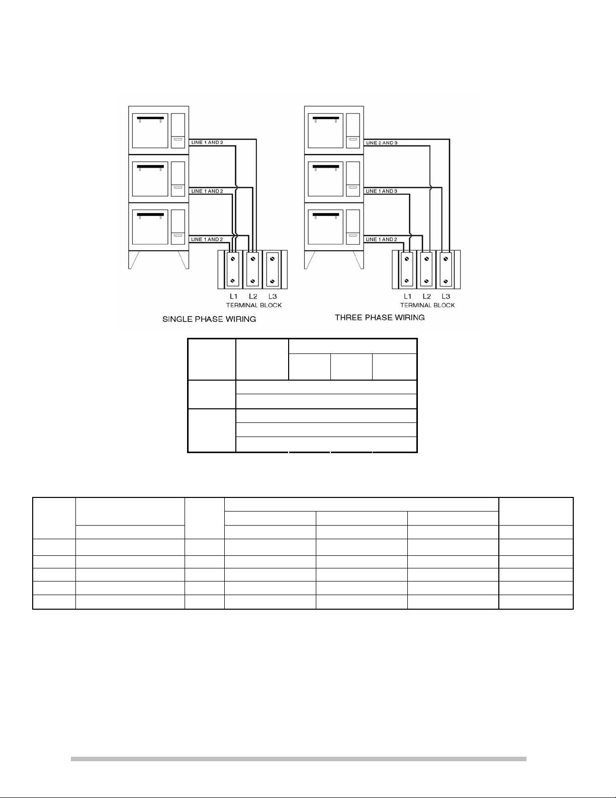
INTERCONNECTING THE OVENS
If the oven is assembled as a 2 deck
model, remove the wire from one of the
Stacking Kit envelopes and cut it in half.
Strip the cut ends of the wires 3/4 inch
and install them into the terminal block of
the top oven. Snap a 3/4 inch plastic
bushing from one of the Stacking Kit
envelopes into the hole in the bottom of
the top oven and run the wires from the
top oven through it to the terminal block in
the bottom oven. Connect the top oven
wires into the terminal block with the wires
from the bottom oven. Refer to the wiring
diagram in this manual for the correct
phasing of the wires.
If the oven is assembled as a 3 deck
model, remove the wires from all three
Stacking Kit envelopes and cut one
half. Use the 2 full length wires to connect
to the top deck and the cut wire to connect
to the middle deck. Refer to the figure
below or the wiring diagram in back of this
manual for the correct wire grouping at the
bottom oven terminal block.
in
4
Page 7
OVEN PHASING
MODEL
NO.
DO36I
DO36L
D036
DO362
D0363
Power
Supply
Terminal
Block
1ST
Deck
OVEN
2ND
Deck
3RD
Deck
L1 X X X Single
Phase
L2 X X X
L1 X X
Three
Phase
L2 X X
L3 X X
LOAD REQUIREMENTS
LOADING THREE PHASE AMPS
KW PER PHASE
LI L2 L2 L3 L3 L1
TOTA
L Kw
208 VOLT 240 VOLT 480 VOLT
L1 L2 L3 L1 L2 L3 L1 L2 L3 208V 240V
6 0 0 6 28.8 28.8 0 25 25 0 12.5 12.5 0 28.8 25
6 0 0 6 28.8 28.8 0 25 25 0 12.5 12.5 0 28.8 25
6 0 0 6 28.8 28.8 0 25 25 0 12.5 12.5 0 28.8 25
6 0 6 12 50 28.8 28.8 43.3 25 25 21.7 12.5 12.5 57.7 50
6 6 6 18 50 50 50 43.3 43.3 43.3 21.7 21.7 21.7 86.5 75
SINGLE
PHASE AMPS
5
Page 8
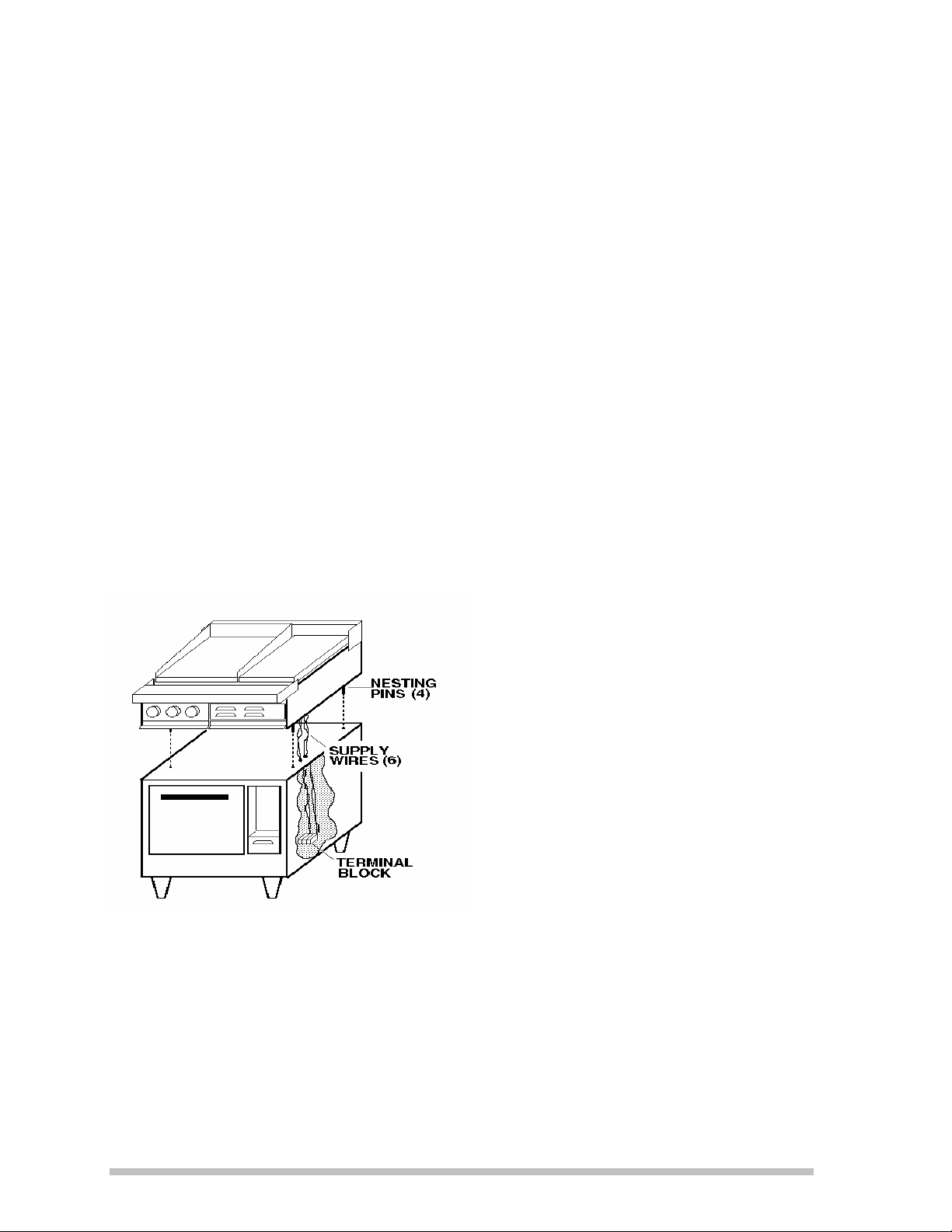
RANGE ASSEMBLY
INSTALLATION ON OVEN BASE
Remove all the plastic plug buttons from
the top of oven(s).
Lay a 2 X 4 or cardboard corner pad
across the top of the oven.
Lift the range top off of the shipping skid
and place it on top of the oven so that the
front edge of the range top is sitting on the
2 X 4 and is elevated off of the oven top.
Feed the two groups of power supply
wires through the two holes in the oven
top until all the wire slack is inside the
oven control compartment.
Lift the front of the range top and remove
the 2 X 4.
Allow the range top to set into place so
that the pins in the bottom if the range top
nest into the holes in the top of the oven
base.
ELECTRICAL CONNECTION
The electrical connection must be made in
accordance with local codes or in the
absence of local codes with NFPA No. 70
latest edition (in Canada use: CSA STD.
C22.1)
Supply wire size must be large enough to
carry the amperage load for the range
being installed. Wire size information can
be found on the range data plate.
This range can be installed on both single
and three phase supplies and is shipped
from the factory un-phased.
The range top wires connect into a
terminal block located in the oven base
control compartment.
6
Page 9

PHASING RANGE ASSEMBLY
Follow the drawings, below, to group the supply wires to match the power phase.
THREE PHASE SINGLE PHASE
LOAD REQUIREMENTS
For proper supply wire and circuit breaker size, refer to the chart below.
THREE PHASE LOADING NOMINAL AMPS PER LINE
Star
Model
Number
136SB 36S 6.0 10.0 5.0 21.0 45.8 66.7 62.5 39.7 57.8 54.2 19.9 28.9 27.1 101.0 87.5
N/A 72S #1 6.0 10.0 5.0 21.0 45.8 66.7 62.5 39.7 57.8 54.2 19.9 28.9 27.1 101.0 87.5
N/A 72S #2 6.0 10.0 5.0 21.0 45.8 66.7 62.5 39.7 57.8 54.2 19.9 28.9 27.1 101.0 87.5
R36C RF21S 6.6 10.0 5.0 21.6 48.3 69.2 62.5 41.9 59.9 54.2 20.9 30.0 27.1 103.8 90.0
N/A RF42S#1 6.6 10.0 5.0 21.6 48.3 69.2 62.5 41.9 59.9 54.2 20.9 30.0 27.1 103.8 90.0
N/A RF42S#2 6.6 10.0 5.0 21.6 48.3 69.2 62.5 41.9 59.9 54.2 20.9 30.0 27.1 103.8 90.0
TOP ONLY
Number
Lang
Model
Total
K.W. PER PHASE
L1 - L2 L2 -L3 L3 -L1
5.0 5.0 5.0 15.0 41.7 41.7 41.7 36.1 36.1 36.1 18.1 18.1 18.1 72.1 62.5
KW
Conn
208 VOLT 240 VOLT 480 VOLT
L1 L2 L3 L1 L2 L3 L1 L2 L3
THREE PHASE
SINGLE
PHASE
208V 240V
7
Page 10

INITIAL START-UP
OPERATION
The preservatives must be cleaned off the
oven front before it is heated. Wipe the
oven front with a damp rag and a mild
soap solution, rinse with warm water and
a damp rag, and then completely dry the
oven front.
Before the initial use of the oven it must
be allowed to thoroughly dry the elements
out. This is accomplished by setting the
top and bottom oven 3-heat switches to
the "Low" position and the thermostat to
350 degrees. Allow the oven to heat until
all vapor and smoke has been eliminated.
Somewhere along the rising temperature
curve between 250 and 350 degrees a
moderate amount of smoke will issue from
within the oven. Preservative oils and oil
accumulated during manufacture will
come off as smoke at these temperatures.
Do not be alarmed.
NORMAL OPERATION
PREHEATING
The oven will not bake uniformly if not
allowed to thoroughly preheat before
loading the product. To compensate for
the temperature loss during loading, set
the oven thermostat 50
desired cooking temperature,
then reset the thermostat to the proper
temperature after closing the oven door.
The oven can be preheated with the 3Heat switches set on any position,
however, the fastest preheat will be
accomplished with both the switches set
to the "High" position. Once the oven is at
the set temperature and the product is
loaded reset the 3-Heat switches to their
proper setting. An indicator light, located
below the oven thermostat knob, will go
out once the oven has recieved the set
temperature. Allow the oven indicator
lamp to cycle on and off at least two times
during the preheat.
degrees over the
load the oven,
OVEN RACK
The oven is equipment with a removable
rack as standard. Baking pies, bread, or
for roasting operations the rack can be
placed directly on the metal deck and the
pans placed on the rack. For cakes or
pastries the rack can be slid into the rack
supports, located about halfway up the
oven sides, and the pans placed on the
rack in this raised position.
8
Page 11

CONTROL PANEL
3-HEAT SWITCHES
While the oven thermostat controls the
temperature, the 3-Heat switches control the
amount of power from the upper and lower
elements. Setting the top element 3-Heat
switch to "High" will burn (or broil) the tops
and setting the bottom 3-Heat switch to "Low"
will not cook the bottom of most products. Set
the 3-Heat switches to achieve the best
uniformity between the top and bottom of the
Class of
product
Average
Temperature
Switch Settings Rack Position
Top Bottom
product. Best results for baking will be
accomplished with the top 3-Heat switch set to
the "Low" position and the bottom 3-Heat
switch set to either "Medium" or "High".
The following Temperature Switch Setting and
Rack Position chart is suggested as a guide in
baking the various classes of product. Be
aware this chart is only a suggestion
temperature, switch settings and rack
positions will be arrived at through experience.
Pie 375-425 Low Medium On Deck
Rolls 375-400 Low High Rack Support
Cake 350-400 Low High Rack Support
Pastries 325-375 Low High Rack Support
Bread 425-450 Low Medium On Deck
. Correct
Roast 300-325 Low Medium On Deck
9
Page 12

PAN PLACEMENT
Place the pan in the center of the oven
rack for the best baking results. Keep the
oven door closed as much as possible.
Excessively opening the oven door will
cool the front section of the oven and the
products placed near the opening will
bake slower.
VENT CONTROL
The oven is supplied with an oven vent
control located above the thermostat dial.
If cooking products with high moisture
content open the vent by pulling the knob
out. The moisture will be vented out the
back of the oven as steam. If the
products require a moist baking
environment push the vent damper
closed.
TIMER
A 60 minute mechanical timer is supplied
as standard equipment. To set, turn the
dial until the desired time is at the top of
the dial. If setting the timer for less than
10 minutes the dial must first be turned
past the 10 minute mark then reset to the
required time. Once the timer has timedout it will sound a bell for about 5 seconds
then automatically turn off.
10
Page 13

PRODUCTIVE MAINTENANCE
"Productive Maintenance" is defined as a means of keeping the appliance as efficient and productive
after years of service as it was when new.
CLEANING
Cleaning the appliance on a regular basis will assure years of efficient performance and
maintain the gleaming appearance it has when new.
Clean the exterior of the oven using a mild soap and water solution. Rinse with clear water
and a damp rag.
Do not
CAUTION
The oven interior must be cleaned with a cleaner that states it is "Safe on
Aluminum". Use of any other cleaner will severely damage the coating on the
inside of the oven and it can not be repaired.
Pay particular attention around the door opening, door edges and at the bottom of the door
so the door continues to close tightly. Should the paint around the door opening begin to
wear off, it can be recoated using a high temperature silver paint found in any hardware
store.
use a pressure washer of any kind to clean the appliance exterior or interior.
THERMOSTAT CALIBRATION
All thermostats are factory calibrated and are extremely reliable mechanical devices.
Thermostat calibration should be attempted only when continued experience indicates
inaccurate cooking temperatures and then only after the calibration of the thermostat has
been thoroughly checked.
However, as the appliance becomes older the thermostat should be checked once a year in
order to make minor adjustments to the calibration.
CALIBRATION CHECK PROCEDURE
Locate an oven thermometer or thermocouple in the center of the oven cavity.
Set the thermostat to 350°F degrees, the upper element 3-Heat switch to "Low", and the
lower element 3-Heat switch to "High".
Allow the oven to heat for at least one hour before attempting any calibration check.
Watch the red indicator lamp below the thermostat dial. When the lamp comes on the oven
elements are "cycling on", when the indicator lamp goes out the elements are "cycling off".
After the oven has heated of an hour record the temperature of the oven when the indicator
lamp "cycles on".
Allow the oven to continue heating and record the temperature when the indicator lamp
"cycles off".
Continue taking the "cycle on" and "cycle off" readings three times.
After 3 complete "cycles" average the six temperature readings (add them up and divide by
6). The average temperature should be within 25 degrees, plus or minus, of 350°F degrees.
11
Page 14

CALIBRATION ADJUSTMENT
A 1/16 inch flat blade screwdriver with a 2 inch shaft is required to adjust the thermostat.
Maintain the oven temperature at 350°F degrees.
Without turning the thermostat dial, pull it off the shaft of the thermostat.
Locate the screw at the base of the thermostat shaft; this is the thermostat calibration screw.
Insert a small flat blade screwdriver down the thermostat shaft until it contacts the screw.
Grasp the thermostat shaft so it does not move while turning the calibration screw.
Use caution when making adjustments to the thermostat, a 1/8 turn of the calibration screw
will adjust the oven temperature about 5 to 7 degrees.
To raise the oven temperature, turn the calibration screw Counter-Clock-Wise.
To lower the oven temperature, turn the calibration screw Clock-Wise.
Reinstall the oven knob and recheck the oven temperature
.
12
Page 15

INSTALLATION TROUBLE SHOOTING GUIDE
SYMPTOM PROBLEM CAUSE
Not Heating Breakers off
Reset Breakers
Not Connected to Power
Improper Phasing at Terminal
Block
Defective Thermostat
Connect to Power
Correct Phasing
Replace Thermostat
One Deck Works Others Do
Not
Internal Circuit Breakers off
Ovens Not Interconnected
Improper Phasing at Terminal
Block
Reset Breakers
Connect all Decks to Lower
Terminal Block
Correct Phasing
Circuit Breakers Trip Supply and Oven Voltage Do
Not Match
Thermostat Capillary Tube
Shorted to Element
Correct Voltage Mismatch
Replace Thermostat to Clear
Short
Too Long To Preheat Supply and Oven Voltage Do
Not Match
"3-Heat" Switches Set on Low
Correct Voltage Mismatch
Set Switches to High
13
Page 16

SK2423 Rev. - 6/08/09
Model:
DO36 Deck Oven
LA36 Deck Oven
2
1
3
5
6
7
1
9
1
10
11
12
13
14
15
16
8
4
See Detail A
See Detail B
Page 17

PARTS LIST June 8, 2009, Rev -
Model No: DO36
36” Bake Deck Oven
Key
Number
1 2C-20103-02 37 SCRW SM PLT 10 X .5 PHLSL
2 N9-LA36-159 1 TOP LA OVEN S/S DO36L (LOWER STACKED UNITS)
N9-LA36-159-1 1 TOP LA OVEN S/S DO36
3 2N-11050-25 2 ELE 36OVN 240V O/S 1.8KW DO36-240VM
2N-11050-29 2 ELMNT 36” OVEN 480V O/S DO36-440VM, DO36-480V, CLDO36L-440V
2N-11050-31 2 ELE 36”OVN 208V O/S 1.8KW DO36-208VM
4 2N-11050-26 2 ELE 36OVN 240V I/S 1.2KW DO36-240VM
2N-11050-30 2 ELMNT 36” OVEN 480V I/S DO36-440VM, DO36-480V, CLDO36L-440V
2N-11050-32 2 ELE 36”OVN 208V I/S 1.2KW DO36-208VM
5 P9-50301-09 12 LONG ELEMENT CLIP S/S
6 P9-50301-10 12 SHORT ELEMENT CLIP
7 2C-20301-15 8 NUT HEX 10-32 PLTD
8 N9-LA36-109-1 1 CAPILLARY SHIELD
9 2P-70901-05 1 PLGBTNBLKPLSTC 3/4DP-750
10 2E-31200-02 1 LUG GROUNDING UL APPROVED
11 2C-20103-01 2 SCRW SM PLT 10X7/8 PHIL
12 2E-30500-07 1 TRM BLOCK 3PLELRGE 125AMP
13 N9-LA36-128 1 SWITCH DOOR ASSY
14 N9-LA36-193 1 DOOR ASSY A/L
15 2M-60301-43 1 DIE CAST PLT LANG SATIN
16 N9-LA36-184 1 DECK CHANNEL ASSY A/L
NI 2A-72500-06 4 LEG 5 1/2 W/BOLT DOWN ADJ CLDO36L-440V
NI 2B-50200-09 1 RACK 36 OVEN
NI 2B-50200-52 1 RACK 36 OVEN CRUISE LINE CLDO36L-440V
Part
Number
Qty
Per
Description
1
IMPORTANT: WHEN ORDERING, SPECIFY VOLTAGE OR TYPE GAS DESIRED PAGE
2
INCLUDE MODEL AND SERIAL NUMBER OF
Some items are included for illustrative purposes only and in certain instances may not be available.
Star Manufacturing International, Inc.
Page 18

SK2424 Rev. - 6/08/09
Model:
DO36 Deck Oven, Details A & B
LA36 Deck Oven, Details A & B
33
1
3
5
11
10
12
13
14
15
17
18
20
21
22
23
24
25
28
29
30
15
31
32
27
26
19
16
6
7
8
9
4
2
Detail A
Detail B
Page 19

PARTS LIST June 8, 2009, Rev -
Model No: DO36
36” Bake Deck Oven, Details A & B
Key
Number
1 N9-LA36-116 1 VENT PIPE ASSY
2 2T-30402-07 1 STAT ADJ 550o 48 C/T
3 2E-30304-35 2 SWTROT3HT 240/480VAC20AMP
4 2J-30801-01 1 TIMER MECHANICAL LONG
5 N9-LA36-130 1 CONTROL SLIDE ASSY
6 2C-20103-02 37 SCRW SM PLT 10 X .5 PHLSL
7 2C-20303-01 1 NUT HX SS 1/4-20
8 2R-70701-25 1 KNOB DAMPER BLACK PLAIN
9 Y9-70701-10-1 2 KNOB 3-HEAT 208-240V
10 Y9-70701-12-1 1 KNOB 550o A PHANTOM
11 Q9-70701-09-1 1 KNOB MANUAL TIMER PHANTOM
12 2J-31601-01 1 PILOT LT 250V 6LEAD BLK 208V, 240V, 440V
12 2J-31601-02 1 PILOT LT 480V 6LEAD BLK DO36-480V, DO36-480VM
13 2C-20101-77 2 SCRW MS PLT 6-32 X .25
14 2E-31800-01 2 CB 250V50A 1 POLE CRLNGSW DO36-208VM
14 2E-31800-04 1 CB 480V 50A 3-POLE DO36-480V, DO36-480VM, CLDO36L-440V
15 2C-20102-04 4 SCRW PHD ST 8-32X.5 PLTD
16 2C-20102-06 2 SCRW PHD ST 6-32X3/8 PLTD
17 Q9-50312-81 1 BREAKER HOLDER
18 2C-20301-29 2 NUT HEX ACORN 1/4-20 S/S
19 2C-20204-02 2 WASHER SS 1/4 SPLIT LOCK
20 N9-LA36-142 1 DOOR INSIDE PANEL
21 2H-LA36-312 1 INSULATION DOOR #2
22 2H-LA36-311 1 INSULATION DOOR #1
23 2A-50800-07 2 TENSION DISC STD OVEN
24 2A-LA36-145 2 DOOR RODS LA36
25 2A-LA36-146 2 DOOR PIPE LA36
26 2P-51001-01 1 SPRING OVN LH DOOR
26 2P-51001-02 1 SPRING OVN RH DOOR
27 2C-20105-04 2 SCREW SET 1/4-20X1/2
28 2C-20101-24 3 SCRW MS PLT 10-32 X .375
29 K9-60301-43-1 1 DIE CAST LOG + TINNERMAN
30 P9-50312-79 RANGE HANDLE
31 2R-50800-91 1 DOOR HANDLE
32 2C-20101-10 2 SCRW THD MS 1/4-20X2 1/4
33 Y9-50300-38 1 HANDLE MARINE MARINE APPLICATIONS
Part
Number
Qty
Per
Description
1
IMPORTANT: WHEN ORDERING, SPECIFY VOLTAGE OR TYPE GAS DESIRED PAGE
2
INCLUDE MODEL AND SERIAL NUMBER OF
Some items are included for illustrative purposes only and in certain instances may not be available.
Star Manufacturing International, Inc.
Page 20

WIRING DIAGRAM
15
Page 21

1
2ND DECK
3RD DECK
TERMINAL BLOCK
1ST DECK
L1 L2 L3
LA-336S "
USE ON ALL E SERIAL NUMBERS
6.0
6.0
2
36S RANGE
LA-236S "
LA-136S OVEN
6.0
6.0
6.0
10.0
0.0
0.0
1
2L1CL2
3
1
5
NUMBER
MODEL
L1 L2 L2 L3 L3 L1
KW PER PHASE
LOADING
C21L1
3
L2
4
2ND AND 3RD DECK
WIRING IDENTICAL
TO 1ST DECK
OVEN WIRING
2
2
3
4
5
6
CONNECT WIRES FROM RANGE
TOP OR ADDITIONAL DECKS TO
LOWER OVEN TERMINAL BLOCK
AS SHOWN AT RIGHT
7
CIRCUIT BREAKER
SPEED UNIT
6 HEAT SWITCH
3 HEAT SWITCH
PILOT LAMP
1
HEAT ELEMENT
THERMOSTAT
36S-10
36S-20
36S-2
36S-3A
36S-0
MODEL DESIGNATION
SCALE:
UNLESS OTHERWISE SPECIFIED
DIMENSIONS ARE IN INCHES
ANGLES
± .5°
.XXX ± .015
.XX ± .03
TO FIT
NEXT HIGHER ASSY.
SHEET
OF
2M-61106-01
DRAWING NUMBER REV
DR:
CK:
FRACTIONS DECIMALS
± 1/64
TOLERANCES
DATE:
DATE:
PART NUMBERQTY ITEM DESCRIPTION / MATERIAL
2-1-94
.X ± .05
208/240VAC
LANG MANUFACTURING
TITLE:
LA36 OVEN / 36S RANGE
CREATED BY STUART R. CARTIER
6.0
18.0
50.0
50.0
50.0
43.3
43.3
43.3
86.5
75.0
6.0
12.0
50.0
28.8
28.8
43.3
25.0
25.0
57.7
50.0
0.0
6.0
28.8
28.8
0.0
25.0
25.0
0.0
28.8
25.0
5.0
21.0
45.8
66.7
62.5
39.7
57.8
54.2
101.0
87.5
TOTAL
L1
L2
L3
L1
L2
L3
208V
240V
KW
ELECTRICAL DATA
PHASE
208 VOLT 240 VOLT
THREE PHASE AMPS
L3 2-4-6
-2
SINGLE
PHASE AMPS
21-21
PHASE
THREE
L2
L1
L2
1-532-4-6
2
1
2
-12
SUPPLY
SINGLE
BLOCK
L1
TOP
1-3-5 1
1st DECK 2nd DECK 3rd DECK
1
SEC-1
A
B
B
A
C
SEC-2
A
B
B
A
55
POWER
5
ABC
TERMINAL
GRILL HOT TOP SPEED UNITS
RANGE
ELECTRICAL CONNECTIONS
4
5
2
55
2
OVEN
C
SEC-3
C
B
C
A
C
2000
3000
1
4
4
2134 2134
7
2
1
1667
1
3
2
4
3
1667
1
1667
4
2
3
1
6
TOP ARRANGEMENT
ECN NO.REV DESCRIPTION DR: DATEMFG ENG
TOP SECTION WIRE DIAGRAMS
REVISION BLOCK
D
Page 22

TERMINAL BLOCK
1
4A
8A
8B
8C
8A
1ST DECK
2
5
L1 L2 L3
36S RANGE
LA-236S "
LA-336S "
LA-136 OVEN
3
3
L2
L1
1B
1A2
NUMBER
MODEL
1
2L1C
L2
7
3
5B 5A
L3
1C
4A
8B
8C
C21L1
L2
4
66
7
TO LOWER OVEN TERMINAL
BLOCK
CONNECT WIRES FROM RANGE
TOP TO OVEN CIRCUIT
BREAKER. CONNECT WIRES
FROM ADDITIONAL DECKS
6 HEAT SWITCH
2ND DECK
1
3
4
5
6
3 HEAT SWITCH
PILOT LAMP
CIRCUIT BREAKER
SPEED UNITS
3RD DECK
2ND AND 3RD DECK
WIRING IDENTICAL
TO 1ST DECK
3
2
2
1
36S-10
36S-20
HEAT ELEMENT
THERMOSTAT
1
36S-3A
2
36S-2
3
36S-0
OVEN WIRING
MODEL DESIGNATION
SCALE:
NONE
OF
UNLESS OTHERWISE SPECIFIED
DIMENSIONS ARE IN INCHES
± 1/64
ANGLES
± .5°
.XXX ± .015
.XX ± .03
.X ± .05
NEXT HIGHER ASSY.
480 VAC
SHEET
6.0
USE ON ALL E SERIAL NUMBERS
6.0
6.0
18.0
21.7
21.7
21.7
PART NUMBERQTY ITEM DESCRIPTION / MATERIAL
FRACTIONS DECIMALS
TOLERANCES
DR: SRC
CK:
DATE:
DATE:
2-1-94
LANG MANUFACTURING
TITLE:
LA36 OVEN / 36S RANGE
CREATED BY STUART R. CARTIER
6.0
0.0
6.0
12.0
21.7
12.5
12.5
6.0
0.0
0.0
6.0
12.5
12.5
0.0
6.0
10.0
5.0
21.0
19.9
28.9
27.1
L1 L2 L2 L3 L3 L1
TOTAL
L1
L2
L3
KW PER PHASE
LOADING
ELECTRICAL DATA
KW
PHASE
480 VOLT
AMPS
L3 2-4-6
-2
BREAKER
POWER
THREE
SUPPLY
ABC
L1
L2
CONNECT TO
BREAKER
OVEN CIRCUIT
1-5
31
1st DECK 2nd DECK 3rd DECK
BOTTOM DECK TERMINAL BLOCK
2
GRILL HOT TOP SPEED UNITS
RANGE TOP
ELECTRICAL CONNECTIONS
UPPER OVENS CONNECT TO
OVEN 3 POLE
CIRCUIT
L1
L2
L3
TO BREAKER TO BREAKER TO BREAKER
123456
B
A
C
SEC-1
TOP ARRANGEMENT
A
B
SEC-2
A
B
B
A
C
SEC-3
C
B
C
A
C
2000
4
2
4
4
3
2
3000
1
ECN NO.REV DESCRIPTION DR: DATEMFG ENG
TOP SECTION WIRE DIAGRAMS
1667
1
1667
1
1667
2
REVISION BLOCK
2M-61106-10
DRAWING NUMBER REV
D
-
21-
1
2134 2134
4
2
7
2
1
3
1
4
3
6
Page 23

Page 24

STAR MANUFACTURING GROUP
Star - Holman - Lang - Wells - Bloomeld
10 Sunnen Drive, St. Louis, MO 63143 U.S.A.
(800) 807-9054 (314) 781-2777
Parts & Service (800) 807-9054
www.star-mfg.com
 Loading...