

Page 1
Installation,
Operation, and
Maintenance, Instructions
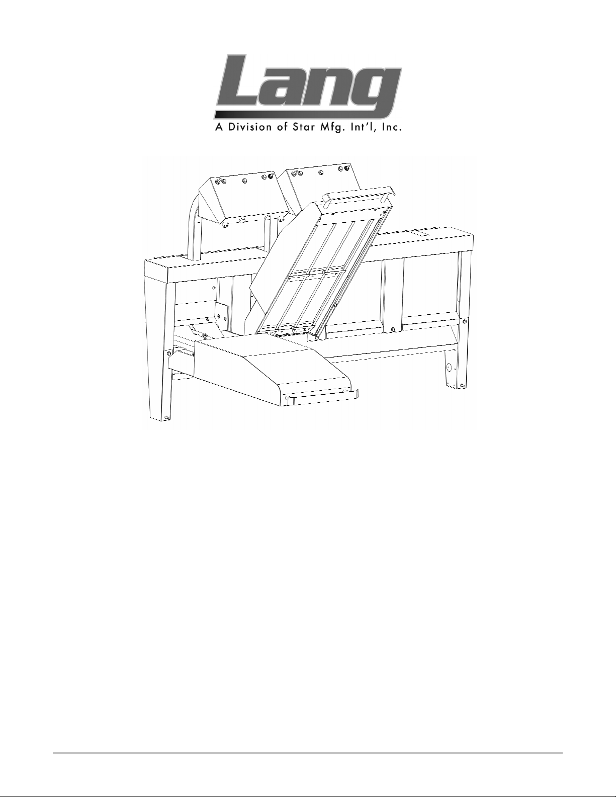
Electric Clamshell
Model:
CSE12-1-208V
CSE12-1-240V
Star Manufacturing International 10 Sunnen Drive St. Louis, MO 63143
Part Number: 2M-W364 Phone: 314-781-2777 Fax: 314-781-2714
Rev. - WWW.STAR-MFG.COM December 1, 2006
Page 2

THE INFORMATION IN THIS MANUAL IS CRUCIAL AND MUST BE
RETAINED FOR FUTURE REFERENCE. READ, UNDERSTAND AND
FOLLOW THE INSTRUCTIONS AND WARNINGS CONTAINED IN THIS
MANUAL.
DANGER
WARNING
CAUTION
NOTICE
POTENTIALLY HAZARDOUS SITUATION WHICH, IF NOT
AVOIDED, COULD RESULT IN DEATH.
POTENTIALLY HAZARDOUS SITUATION WHICH, IF NOT
AVOIDED, COULD RESULT IN DEATH OR SERIOUS INJURY.
POTENTIALLY HAZARDOUS SITUATION WHICH, IF NOT
AVOIDED, MAY RESULT IN MINOR OR MODERATE INJURY.
Helpful operation and installation instructions and tips are
present.
FOR YOUR SAFETY
DO NOT STORE OR USE GASOLINE OR OTHER FLAMMABLE VAPORS
AND LIQUIDS IN THE VICINITY OF THIS OR ANY OTHER APPLIANCE.
WARNING: IMPROPER INSTALLATION, ADJUSTMENT, ALTERATION,
SERVICE OR MAINTENANCE CAN CAUSE PROPERTY DAMAGE, INJURY
OR DEATH. READ THE INSTALLATION, OPERATING AND MAINTENANCE
INSTRUCTIONS THOROUGHLY BEFORE INSTALLING OR SERVICING THIS
EQUIPMENT.
Model #: Purchased From:
Serial #:
Location:
Date Purchased:
Purchase Order #:
Date Installed:
For Service, Call:
Page 3

TABLE OF CONTENTS
CHAPTER PAGE
TABLE OF CONTENTS ...................................................................................... 3
READ FIRST ........................................................................................................ 4-5
SAFETY PROCEDURES ..................................................................................... 6
EQUIPMENT DESCRIPTION ............................................................................. 7
UNPACKING........................................................................................................ 8
INSTALLATION.................................................................................................. 9
INITIAL START UP AND OPERATION............................................................ 10
MAINTENANCE & CLEANING......................................................................... 11
TROUBLE SHOOTING ....................................................................................... 12
EXPLODED VIEW............................................................................................... 14
PARTS LIST ......................................................................................................... 15
WIRING DIAGRAM ............................................................................................ 16
ETL File 68964 Rev. - 2006
3
Page 4
IMPORTANT READ FIRST IMPORTANT
CAUTION
CAUTION
CAUTION
DANGER
WARNING
WARNING
NOTICE
THE UNIT IS EXTREMELY HEAVY. FOR SAFE HANDLING, INSTALLER
SHOULD OBTAIN HELP AS NEEDED, OR EMPLOY APPROPRIATE
MATERIALS HANDLING EQUIPMENT (SUCH AS A FORKLIFT, DOLLY, OR
PALLET JACK) TO REMOVE THE UNIT FROM THE SKID AND MOVE IT TO
THE PLACE OF INSTALLATION.
ANY STAND, COUNTER OR OTHER DEVICE ON WHICH UNIT WILL BE
LOCATED MUST BE DESIGNED TO SUPPORT THE WEIGHT OF THE UNIT.
SHIPPING STRAPS ARE UNDER TENSION AND CAN SNAP BACK WHEN
CUT.
THIS APPLIANCE MUST BE GROUNDED AT THE TERMINAL PROVIDED.
FAILURE TO GROUND THE APPLIANCE COULD RESULT IN
ELECTROCUTION AND DEATH.
INSTALLATION OF THE UNIT MUST BE DONE BY PERSONNEL
QUALIFIED TO WORK WITH ELECTRICITY AND PLUMBING. IMPROPER
INSTALLATION CAN CAUSE INJURY TO PERSONNEL AND/OR DAMAGE
TO EQUIPMENT. UNIT MUST BE INSTALLED IN ACCORDANCE WITH ALL
APPLICABLE CODES.
BROILER ELEMENTS CAN IGNITE GREASE FIRES ON THE GRIDDLE
SURFACE WHICH MAY RESULT IN PROPERTY DAMAGE, SERIOUS
INJURY OR DEATH. ENSURE GRIDDLE SURFACE IS SLOPPED DOWN
FROM BACK TO FRONT BY AT LEAST ¼” BEFORE COOKING
The data plate is located behind hood wrap on hood frame. The hood
voltage, wattage, serial number, wire size, and clearance specifications
are on the data plate. This information should be carefully read and
understood before proceeding with the installation.
NOTICE
NOTICE
CAUTION
CAUTION
WARNING
CAUTION
NOTICE
The installation of any components such as a vent hood, grease
extractors, fire extinguisher systems, must conform to their applicable
National, State and locally recognized installation standards.
During the first few hours of operation you may notice a small amount of
smoke coming from the unit, and a faint odor from the smoke. This is
normal for a new unit and will disappear after the first few hours of use.
ALWAYS KEEP THE AREA NEAR THE APPLIANCE FREE FROM
COMBUSTIBLE MATERIALS.
KEEP FLOOR IN FRONT OF EQUIPMENT CLEAN AND DRY. IF SPILLS
OCCUR, CLEAN IMMEDIATELY, TO AVOID THE DANGER OF SLIPS OR
FALLS.
KEEP WATER AND SOLUTIONS OUT OF CONTROLS. NEVER SPRAY OR
HOSE CONTROL CONSOLE, ELECTRICAL CONNECTIONS, ETC.
MOST CLEANERS ARE HARMFUL TO THE SKIN, EYES, MUCOUS
MEMBRANES AND CLOTHING. PRECAUTIONS SHOULD BE TAKEN TO
WEAR RUBBER GLOVES, GOGGLES OR FACE SHIELD AND
PROTECTIVE CLOTHING. CAREFULLY READ THE WARNING AND
FOLLOW THE DIRECTIONS ON THE LABEL OF THE CLEANER TO BE
USED.
The plunger switch should be compressed approximately 1/8” with the
hood in the up position.
ETL File 68964 Rev. - 2006
4
Page 5
IMPORTANT READ FIRST IMPORTANT
NOTICE
WARNING
CAUTION
Service on this, or any other, LANG appliance must be performed by
qualified personnel only. Consult your LANG authorized service agent
directory or call the factory at 1-800-807-9054, or WWW.STAR-MFG.COM
For the service agent nearest you.
HIGH VOLTAGES ARE PRESENT INSIDE THIS APPLIANCE WHEN THE
UNIT IS PLUGGED/WIRED INTO A LIVE RECEPTACLE. BEFORE
REPLACING ANY PARTS, DISCONNECT THE UNIT FROM THE ELECTRIC
POWER SUPPLY.
USE OF ANY REPLACEMENT PARTS OTHER THAN THOSE SUPPLIED BY
LANG OR THEIR AUTHORIZED DISTRIBUTORS CAN CAUSE BODILY
INJURY TO THE OPERATOR AND DAMAGE TO THE EQUIPMENT AND
WILL VOID ALL WARRANTIES.
ETL File 68964 Rev. - 2006
5
Page 6

SAFETY PROCEEDURES
Lockout Procedure
1. Announce lockout to other personnel.
2. Turn power off at main panel.
3. Test lockout by turning power switch on and observing if elements come on. Check heater circuit
with voltmeter.
4. Perform necessary repairs or tests.
5. Clear unit of personnel before restarting.
6. Turn power on at main panel.
7. Announce unit is “ON” to other personnel.
Safety Precautions
The Manufacturer, Star Manufacturing, hereby disclaims any and all responsibility for injury, damage,
loss or other claim that may occur to person or property from improper alteration, modification, addition,
operation, maintenance or service, whether it be mechanical, electrical, or otherwise, which may occur
from such improper alteration, modification, addition, operation, maintenance or service to this piece of
equipment.
Safety Considerations
Your Lang 12-inch Clamshell is manufactured to rigid standards. This equipment is ETL, CETL, or
NSF listed meeting safety and sanitation standards.
The presence of safety equipment control and interlocks on an appliance and attendant components of
installation cannot in and of themselves, assure absolute safety of operation. Diligent, capable, well
trained operators and maintenance personnel, as well as proper programs of operation and maintenance,
are essential to the safe and reliable operation of this appliance.
A. The responsibility of the manufacturer
recommendations for the operation and maintenance of the appliance.
B. Trained qualified and factory-authorized personnel must perform all operation, maintenance and
repair of these appliances. It is the responsibility of the owner / operator
happens.
C. A regular periodic program of cleaning, inspection and maintenance must be established and
comprehensive maintenance records maintained. It is the sole responsibility of the user
schedule and enforce the frequency and scope of these programs in keeping with recommended
practice and with due consideration given to actual operating conditions.
D. The appliance must be operated within the limits it was designed for, which will not exceed the
working limits of any component within the appliance as a whole.
is to supply suitable, comprehensive instructions and
to ensure that this
to establish,
ETL File 68964 Rev. - 2006
6
Page 7

EQUIPMENT DESCRIPTION
Lang Model: CSE12-1
12-Inch Electric Clamshell
Controls
The CSE12-1 Broiler has a power switch located on the right of the pylon
mounted control panel. An indicator light adjacent to the power switch indicates
power when power is on. A micro switch mounted in the clamshell, actuated by
placing the hood in the up “idle” position, switches between full and idle power
settings. A standby circuit, consisting of a momentary contact switch and an
amber indicator light, allows element power to be reduced to idle when the hood is
in the down “cooking” position.
Technical
The broiler, not including the griddle, is standard 208 or 240-volt, single phase.
The voltage must be specified when ordering.
ETL File 68964 Rev. - 2006
7
Page 8

Receiving the Unit
Upon receipt, check for freight damage, both visible and concealed. Visible
damage should be noted on the freight bill at the time of delivery and signed by the
carrier's agent. Concealed loss or damage means loss or damage, which does not
become apparent until the merchandise has been unpacked. If concealed loss or
damage is discovered upon unpacking, make a written request for inspection by the
carrier's agent within 15 days of delivery. All packing material should be kept for
inspection. Do not return damaged merchandise to Star Manufacturing
International. File your claim with the carrier.
Location
Prior to un-crating, move the unit as near its intended location as practical.
The crating will help protect the unit from the physical damage normally associated
with moving it through hallways and doorways.
Un-crating
The unit will arrive completely assembled inside a wood frame covered by
cardboard box and strapped to a skid. Remove the cardboard cover, cut the
straps and remove the wood frame.
The unit may now be removed from the skid.
CAUTION
CAUTION
CAUTION
THE UNIT IS EXTREMELY HEAVY. FOR SAFE HANDLING, INSTALLER
SHOULD OBTAIN HELP AS NEEDED, OR EMPLOY APPROPRIATE
MATERIALS HANDLING EQUIPMENT (SUCH AS A FORKLIFT, DOLLY, OR
PALLET JACK) TO REMOVE THE UNIT FROM THE SKID AND MOVE IT TO
THE PLACE OF INSTALLATION.
ANY STAND, COUNTER OR OTHER DEVICE ON WHICH THE UNIT WILL
BE LOCATED MUST BE DESIGNED TO SUPPORT THE WEIGHT OF THE
UNIT.
SHIPPING STRAPS ARE UNDER TENSION AND CAN SNAP BACK WHEN
CUT.
UNPACKING
ETL File 68964 Rev. - 2006
8
Page 9

DANGER
INSTALLATION
THIS APPLIANCE MUST BE GROUNDED AT THE TERMINAL PROVIDED.
FAILURE TO GROUND THE APPLIANCE COULD RESULT IN
ELECTROCUTION AND DEATH.
WARNING
WARNING
NOTICE
NOTICE
ELECTRICAL CONNECTION
Ensure griddle is installed per griddle installation instructions.
If installation is a retrofit, locate and drill mounting holes in griddle splasher.
Mount hood with hardware provided.
Electrical service connection is made in the box mounted at the back of the griddle.
MODEL:
CSE12-1
1 EA. 208V 3.8 3.8 N/A N/A N/A 18.3
1 EA. 240V 3.8 3.8 N/A N/A N/A 15.8
2 EA. 208V 3.8 3.8 7.6 N/A N/A N/A 36.5
2 EA. 240V 3.8 3.8 7.6 N/A N/A N/A 31.7
CLEARANCES
Maintain clearances of base appliance. For use only in non-combustible locations.
INSTALLATION OF THE UNIT MUST BE DONE BY PERSONNEL
QUALIFIED TO WORK WITH ELECTRICITY AND PLUMBING. IMPROPER
INSTALLATION CAN CAUSE INJURY TO PERSONNEL AND/OR DAMAGE
TO EQUIPMENT. UNIT MUST BE INSTALLED IN ACCORDANCE WITH ALL
APPLICABLE CODES.
BROILER ELEMENTS CAN IGNITE GREASE FIRES ON THE GRIDDLE
SURFACE WHICH MAY RESULT IN PROPERTY DAMAGE, SERIOUS
INJURY OR DEATH. ENSURE GRIDDLE SURFACE IS SLOPPED DOWN
FROM BACK TO FRONT BY AT LEAST ¼” BEFORE COOKING
The data plate is located behind hood wrap on hood frame. The unit
voltage, wattage, serial number, wire size, and clearance specifications
are on the data plate. This information should be carefully read and
understood before proceeding with the installation.
The installation of any components such as a vent hood, grease
extractors, fire extinguisher systems, must conform to their applicable
National, State and locally recognized installation standards.
AMPS PER LINE THREE
PHASE
VOLTS
kW PER PHASE
L1-L2 L2-L3 L1-L3 TOTAL L1 L2 L3
SINGLE
PHASE
ETL File 68964 Rev. - 2006
9
Page 10

NOTICE
Each unit is preheated, tested and calibrated at the factory before shipment.
However, due to temperature and climate changes during shipment the unit can
absorb moisture and should be dried out before attempting to put it in full operation.
Prior to putting any unit into full time operation at normal cooking temperatures, it
must be thoroughly "seasoned" or dried out. Moisture absorption in the closed
spaces, in the insulation and even inside the heating elements can cause future
trouble if not properly treated.
Before the initial use of the unit, the element must be thoroughly allowed to dry out.
This can be done by cycling the unit on and placing the hood into the down position.
Allow the unit to saturate until all vapor and condensation has been eliminated. For
best operating results allow the unit to thoroughly dry out for 8 to 12 hours.
If the unit is out of use for three or more days, a one-hour preheat schedule should be
used, especially when exposed to high humidity and/or cool temperatures.
During the first few hours of operation you may notice a small amount of
smoke coming from the appliance, and a faint odor from the smoke. This
is normal for a new oven and will disappear after the first few hours of
use.
INITIAL START UP
CAUTION
CAUTION
ALWAYS KEEP THE AREA NEAR THE APPLIANCE FREE FROM
COMBUSTIBLE MATERIALS.
KEEP FLOOR IN FRONT OF EQUIPMENT CLEAN AND DRY. IF SPILLS
OCCUR, CLEAN IMMEDIATELY, TO AVOID THE DANGER OF SLIPS OR
FALLS.
GENERAL
Once the griddle has been loaded properly lower the hood over the product.
Elements must not touch product when clamshell® is in the closed position.
OPERATION
ETL File 68964 Rev. - 2006
10
Page 11

MAINTENANCE & CLEANING
WARNING
CAUTION
KEEP WATER AND SOLUTIONS OUT OF CONTROLS. NEVER SPRAY OR
HOSE CONTROL CONSOLE, ELECTRICAL CONNECTIONS, ETC.
MOST CLEANERS ARE HARMFUL TO THE SKIN, EYES, MUCOUS
MEMBRANES AND CLOTHING. PRECAUTIONS SHOULD BE TAKEN TO
WEAR RUBBER GLOVES, GOGGLES OR FACE SHIELD AND
PROTECTIVE CLOTHING. CAREFULLY READ THE WARNING AND
FOLLOW THE DIRECTIONS ON THE LABEL OF THE CLEANER TO BE
USED.
DAILY CLEANING
The CSE12-1 hood is a self-cleaning device. When the hood is in the down
position it will bake off any debris that may accumulate during normal business
operation. DO NOT USE ANY WATER OR CLEANING SOLUTION ON
THE ELEMENTS.
Clean the exterior of the appliance with hot water and mild detergent to maintain a
gleaming appearance.
Wipe drip shield between hood and griddle to remove any grease.
WEEKLY CLEANING
It may be necessary after high use to allow the hood to burn off any carbon build up.
With a cold griddle, lower the hood and allow the hood to cook for 30 minutes.
Additional time may be necessary for more baked-on grease.
ETL File 68964 Rev. - 2006
11
Page 12

TROUBLESHOOTING
Symptoms
What follows is a chart of Symptoms, Possible Causes, and Remedy’s to aid in
diagnosing faults with the oven.
Refer to the Symptoms column to locate the type of failure then to the Possible
Cause for the items to be checked. On the following pages is a chart with the
possible causes and the test to properly identify the problem.
SYMPTOM POSSIBLE CAUSE
Unit will not heat
Unit will not stay up
NOTICE
WARNING
CAUTION
Service on this, or any other, LANG appliance must be performed by
qualified personnel only. Consult your LANG authorized service agent
directory or call the factory at 1-800-807-9054, or WWW.STAR-MFG.COM
For the service agent nearest you.
BOTH HIGH AND LOW VOLTAGES ARE PRESENT INSIDE THIS
APPLIANCE WHEN THE UNIT IS PLUGGED/WIRED INTO A LIVE
RECEPTACLE. BEFORE REPLACING ANY PARTS, DISCONNECT THE
UNIT FROM THE ELECTRIC POWER SUPPLY.
USE OF ANY REPLACEMENT PARTS OTHER THAN THOSE SUPPLIED BY
LANG OR THEIR AUTHORIZED DISTRIBUTORS CAN CAUSE BODILY
INJURY TO THE OPERATOR AND DAMAGE TO THE EQUIPMENT AND
WILL VOID ALL WARRANTIES.
No power to Unit
Defective power switch
Defective micro switch
Defective element
Spring needs to be adjusted
Spring needs to be replaced
TESTS
Possible Cause TEST
No Power to unit
Defective power switch
Defective micro switch
Failed element
Confirm that circuit breakers are on.
Check for voltage at the terminal block. *
Check toggle switch for normal operation.
Check micro switch for normal operation
Remove the wires and check for continuity
across the element*
*A factory authorized service representative should perform this work.
ETL File 68964 Rev. - 2006
12
Page 13

ETL File 68964 Rev. - 2006
13
Page 14

ILLUSTRATED PARTS BREAKDOWN
(SHOWN: 4’ ELECTRIC WITH ONE 12-INCH CLAMSHELL)
Rev. -2006
Sheet A1 of 2
Page 15

PARTS LIST
CSE12-1 ELECTRIC 12-INCH CLAMSHELL
ITEM# PART#
1 2N-11160-32-2 2 Element, 208 Volt, 1600W 208V Only
1A 2N-11160-32-4 2 Element, 240 Volt, 1600W 240V Only
2 2P-51002-15 1 Spring, Hood
3 K9-XLH-709 1 Handle Assy
4 K9-SKXLH7401 1 Hood Mercury Switch Svc Kit
4A 2E-30307-04 2 Switch, Mercury Tilt, Hi-Temp
5 2E-30303-06 1 Toggle Switch, DPDT
6 2J-31601-15 1 Pilot Light 250V 6" Lead Amber CE
7 2J-31601-16 1 Pilot Light 250v 6" Lead Green CE
8 2J-31601-17 1 Pilot Light 250v 6" Lead White CE
9 2E-30500-08 * Terminal Block, 2 Pole, Small 95 Amp
10 2E-30500-02 * Terminal Block, 4 Pole, 30Amp 600V
11 2E-31200-08 * Grounding Lug, 2 Hole
12 2E-30705-01 1 Interlocking ContactorCONTC 2-SPD MTR-COIL 240 VA
13 2J-40302-02 1 Timer Receptacle
14 2E-30600-10 1 Relay, 240V DPDT
15 2E-30303-16 1 Momentary Switch
16 K9-XLH-609 1 Front Hood Wrap
17A K9-XLH-636-2 1 Bridge Cover - 2’ 2’ Griddle
17B K9-XLH-636-3 1 Bridge Cover - 3’ 3’ “
17C K9-XLH-636-4 1 Bridge Cover - 4’ 4’ “
17D K9-XLH-636-5 1 Bridge Cover - 5’ 5’ “
17E K9-XLH-636-6 1 Bridge Cover - 6’ 6’ “
18 K9-XLH-733-1 * Bridge Cover Pylon
19 K9-XLH-659-1 1 Stanchion Cover - R/H
20 K9-XLH-660-1 1 Stanchion Cover - L/H
21B K9-XLH-640-01 1 Control Panel Cover
22A K9-XLH-731-2 1 Conn Box Assy - 2’ Elec 2’ Griddle
22B K9-XLH-737-32 1 Conn Box Assy - 3’ Elec 3’ “ “
22C K9-XLH-737-32 1 Conn Box Assy - 4’ Elec 4’ “ “
22D K9-XLH-737-42 1 Conn Box Assy - 5’ Elec 5’ “ “
22E K9-XLH-737-62 1 Conn Box Assy - 6’ Elec 6’ “ “
22F K9-XLH-735-22 1 Conn Box/Flue Assy - 2’ Gas 2’ Griddle
22G K9-XLH-735-32 1 Conn Box/Flue Assy - 3’ Gas 3’ “ “
22H K9XLH-735-42 1 Conn Box/Flue Assy - 4’ Gas 4’ “ “
22J K9-XLH-735-52 1 Conn Box/Flue Assy - 5’ Gas 5’ “ “
22K K9-XLH-735-62 1 Conn Box/Flue Assy - 6’ Gas 6’ “ “
23 2A-70805-04 2 Bumper
24 K9-XLH-734 1 Bridge To Hood Wire Conduit
25 K9-XLH-703-4 1 Spring Rod
QTY
PER
UNIT
DESCRIPTION
USAGE
(OVEN
MODEL)
Rev. -2006
Page 16

WIRING DIAGRAM
Rev. -2006
 Loading...