

Lang Manufacturing 224ZT Installation Manual
ENVIROZONE-TSTAT
GAS GRIDDLE
Commercial
224ZT, 236ZT, 248ZT, 260ZT, 272ZT
Installation and
Operation
Instructions
2M-W1785 Rev. C 4/23/15
272ZT
IL2412
SAFETY SYMBOL
DO NOT STORE OR USE GASOLINE OR OTHER FLAMMABLE VAPORS AND LIQUIDS IN
The installation of the Appliance must conform to the NATIONAL FUEL GAS CODE "ANSI Z223.1 - LATEST
EDITION" AND ALL LOCAL GAS COMPANY RULES AND REGULATIONS.
IN CANADA INSTALLATION SHALL BE IN ACCORDANCE WITH THE CURRENT CAN/CGA-B149.1 NATURAL
GAS INSTALLATION CODE OR CAN/CGA-B149.2 PROPANE INSTALLATION CODE AND LOCAL CODES WHERE
APPLICABLE.
INSTRUCTIONS TO BE FOLLOWED IN THE EVENT USER SMELLS GAS. THIS INFORMATION
SHALL BE OBTAINED BY CONSULTING YOUR LOCAL GAS SUPPLIER. AS A MINIMUM, TURN
OFF THE GAS AND CALL YOUR GAS COMPANY AND YOUR AUTHORIZED SERVICE AGENT.
IMPROPER INSTALLATION, ADJUSTMENT, ALTERATION, SERVICE OR MAINTENANCE CAN
CAUSE PROPERTY DAMAGE, INJURY OR DEATH. READ THE INSTALLATION, OPERATION
& MAINTENANCE INSTRUCTIONS THOROUGHLY BEFORE INSTALLING OR SERVICING THIS
These symbols are intended to alert the user to the presence of important operating
and maintenance instructions in the manual accompanying the appliance.
FOR YOUR SAFTEY
THE VICINTIY OF THIS OR ANY OTHER APPLIANCE.
POST IN PROMINENT LOCATION
EVACUATE ALL PERSONNEL FROM THE AREA.
WARNING
EQUIPMENT.
WARNING
RISK OF FIRE OR ELECTRIC SHOCK
DO NOT OPEN
WARNING, TO REDUCE THE RISK OF ELECTRICAL SHOCK, DO NOT REMOVE
CONTROL PANEL. NO USER-SERVICABLE PARTS INSIDE.
REPAIRS SHOULD BE DONE BY AUTHORIZED SERVICE PERSONNEL ONLY.
NOTICE
Using any part other than genuine Lang factory supplied parts relieves the manufacturer of all liability.
Lang reserves the right to change speci cations and product design without notice. Such
revisions do not entitle the buyer to corresponding changes, improvements, additions or
replacements for previously purchased equipment.
Due to periodic changes in designs, methods, procedures, policies and regulations, the
specifications contained in this sheet are subject to change without notice. While Lang
Manufacturing exercises good faith efforts to provide information that is accurate, we are
not responsible for errors or omissions in information provided or conclusions reached as a
result of using the speci cations. By using the information provided, the user assumes all risks in con-
nection with such use.
MAINTENANCE AND REPAIRS
Contact your local dealer for service or required maintenance. Please record the model number, serial
number, voltage and purchase & Installation Information in the area below and have it ready when you
call to ensure a faster service.
Model No.:
Serial No.:
Voltage:
1-Phase or 3 Phase:
Purchased From:
Location:
Purchase Date:
Installed Date:
2

PROBLEMS, QUESTIONS or CONCERNS
Before you proceed consult you authorized Lang service agent directory
or
Call the Lang Technical Service & Parts Department at (314) 678-6315
TABLE OF CONTENTS
Specications . . . . . . . . . . . . . . . . . . . . . . . . . . . . . 4
Equipment Description . . . . . . . . . . . . . . . . . . . . . . . . 5
Unpacking . . . . . . . . . . . . . . . . . . . . . . . . . . . . . . . 6
Installation
Leg Installation . . . . . . . . . . . . . . . . . . . . . . . . . . 6
Ventilation & Clearence . . . . . . . . . . . . . . . . . . . . . . 7
Electrical & Gas Connection. . . . . . . . . . . . . . . . . . . . 8
Initial Start-Up
Initial Lighting Procedure . . . . . . . . . . . . . . . . . . . . . 9
Seasoning Cooking Surface . . . . . . . . . . . . . . . . . . . . 9
Operation
Setting the Griddle Temperature . . . . . . . . . . . . . . . . .10
Suggested Times and Temperatures . . . . . . . . . . . . . . .10
Loading the Griddle . . . . . . . . . . . . . . . . . . . . . . . . 11
Sequence of Operation
Power On . . . . . . . . . . . . . . . . . . . . . . . . . . . . . 11
Maintenance
Daily Cleaning . . . . . . . . . . . . . . . . . . . . . . . . . . . 12
Weekly Cleaning . . . . . . . . . . . . . . . . . . . . . . . . .12
Burner Air Shutter Adjustment . . . . . . . . . . . . . . . . . . . 12
Calibration . . . . . . . . . . . . . . . . . . . . . . . . . . . . . 13
Troubleshooting
Symptoms / Possible Causes / Test . . . . . . . . . . . . . . . . 14
Wiring Diagram . . . . . . . . . . . . . . . . . . . . . . . . . . .15 - 17
Exploded View & Parts List . . . . . . . . . . . . . . . . . . . . . 18-23
NOTICE ServiceonthisoranyotherLangappliancemustbeperformedbyqualied
personnel only. Consult your Lang Authorized Service Agent Directory.
You can call technical service at (314) 678-6315 or visit our website
WWW.LANGWORLD.COM for the service agent nearest you.
3
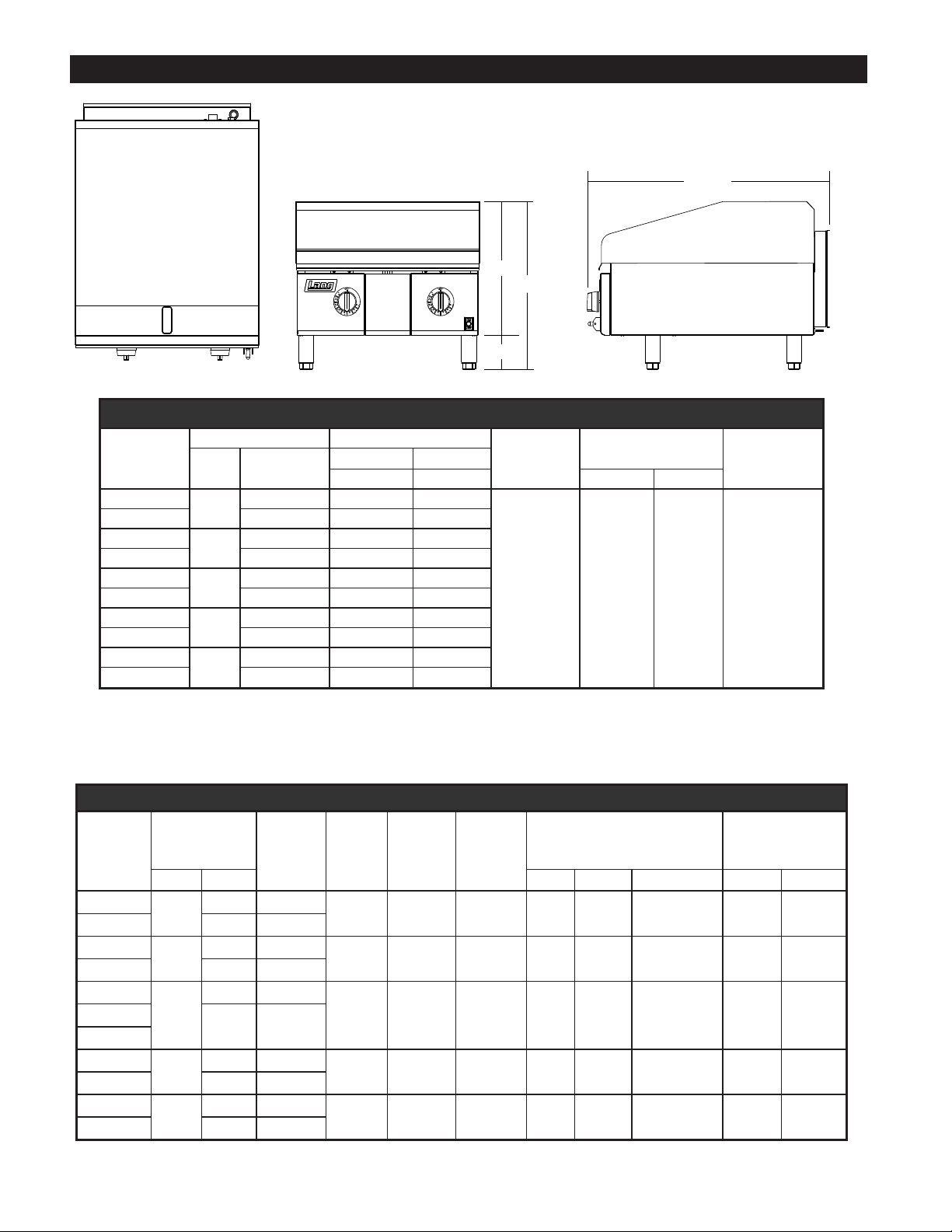
Front Side
Top
31.375”
16.5”
20”
4”
IL2411
EQUIPMENT SPECIFICATIONS
GAS AND ELECTRIC INPUT REQUIRMENTS
MODEL
NUMBER
224ZT
224ZTD 30” 70,000 70,000
236ZT
236ZTD 30” 105,000 105,000
248ZT
248ZTD 30” 140,000 140,000
260ZT
260ZTD 30” 175,000 175,000
272ZT
272ZTD 30” 210,000 210,000
DESCRIPTION TOTAL BTU INPUT
Unit
Width
24”
36”
48”
60”
72”
Griddle Surface
Depths
24” 54,000 54,000
24” 81,000 81,000
24” 108,000 108,000
24” 135,000 135,000
24” 162,000 162,000
NATURAL PROPANE
5” WC 10” WC VOLTAGE AMPS
GAS
CONNECTION
ELECTRICAL
CONNECTION
CORD/PLUG
& PRESSURE
REGULATOR
ONE 3/4” NPT 115 VOLT 2 SUPPLIED
MODEL
NUMBER
224ZT
224ZTD 30 “ 720
236ZT
236ZTD 30 “ 1,080
248ZT
248TDC
260ZT
260ZTD 30 “ 1,800
272ZT
272ZTD 30 “ 2,160
GRILL SURFACE
OVERALL
WIDTH DEPTH SIDES BACK BOTTOM ACTUAL SHIPPING
24 “
36 “
48 “
60 “
72 “
23 “ 552
23 “ 828
23 “ 1,104
30 “ 1,440
23 “ 1,380
23 “ 1,656
SPECIFICATIONS AND INFORMATION
SQUARE
INCHES OF
GRIDDLE
NUMBER
BURNERS
NUMBER OF
OF
CONTROLS
2 2 1 0 “ 5 “ 4 INCH LEG 255 300
3 3 1 0 “ 5 “ 4 INCH LEG 336 400
4 4 2 0 “ 5 “ 4 INCH LEG 435 500248ZTD
5 5 2 0 “ 5 “ 4 INCH LEG 530 625
6 6 2 0 “ 5 “ 4 INCH LEG 610 725
NUMBER
OF GREASE
DRAWERS
CLEARANCE FROM NON-
COMBUSTIBLE SURFACES
4
WEIGHT
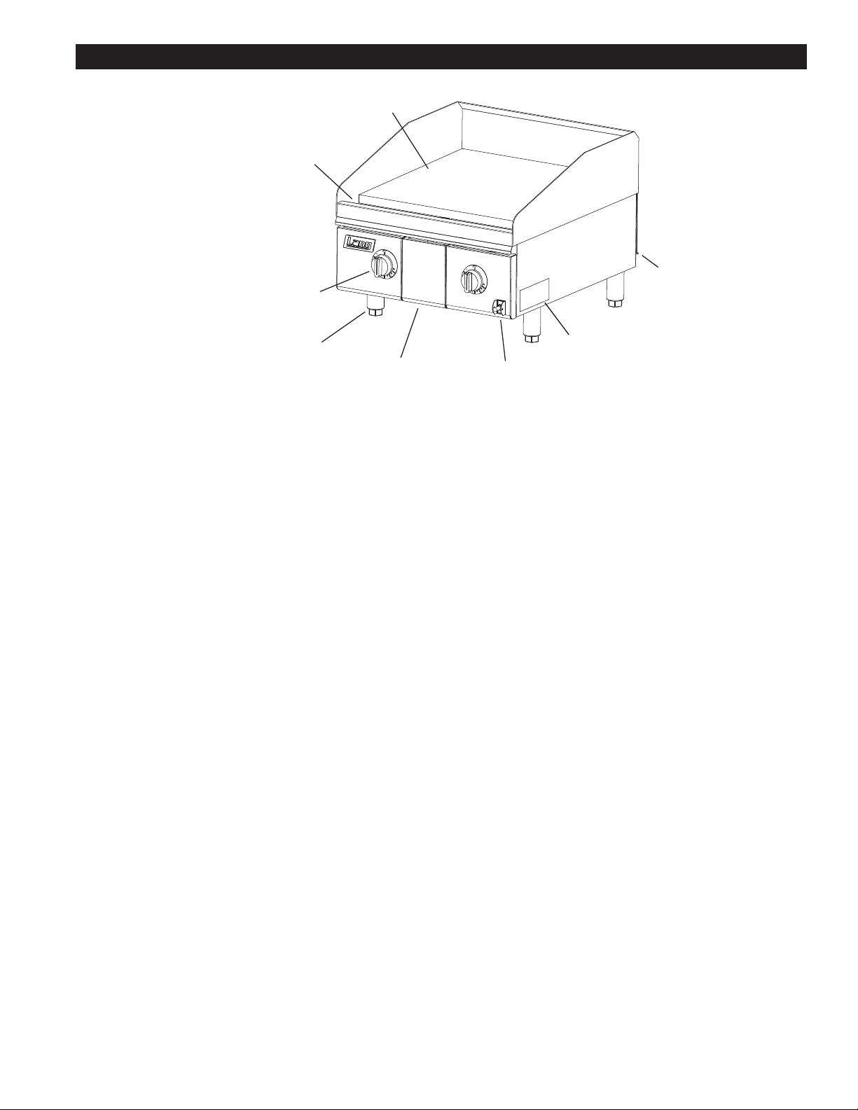
EQUIPMENT DESCRIPTION
1” Griddle Surface
Gutter
Section Temp Dial
Wall Anchor
& Gas Inlet
Adj. Legs
Grease Pan Main Power Switch
Nameplate
IL2410
Exterior Construction
The griddle dimensions are 17” (43.18cm) High, 30” (76.20cm) Deep, and width is dependent on the actual model
number.
The Sides, Bottom, and Rear wall are constructed of double wall stainless steel, which allows closer installation to
combustible surfaces.
The griddle surface is made of 1” thick, highly polished steel to reduce hot and cold spots, recovery problems,
warping, and ensure even heat to the edges of the griddle.
Operation
• Each 12” section has its own snap-action thermostat and gas valve that are fully “ON” or fully “OFF”.
• The control has factory congurable maximum and minimum temperature settings. The maximum temperature
value can be set at 550°F (288°C). The minimum temperature value can be set at 200°F (93°C).
Technical
• Griddle operates on either Natural gas or Propane, which must be specied when ordering.
• It is shipped with a power cord and plug attached.
• Floor space required is 30” (76.20cm) Deep, and width is 2 ft, 3ft, 4ft, 5ft, or 6ft depending on actual model
number.
• The griddle weighs 255, 336, 435, 530, 610 lbs. depending on actual model number.
GriddleGasandVoltageSpecications
The Lang Model can be connected to any 120 Volt source. The gas and electrical specications are listed in the
table on the previous page.
NOTICE The data plate is on the right side of the griddle. The voltage, wattage, serial
number,wiresize,andclearancespecicationsareonthedataplate.This
information should be carefully read and understood before proceeding with
the installation.
5
CAUTION
UNPACKING
Receiving the Griddle
Upon receipt, check for freight damage, both visible and concealed.
Visible damage should be noted on the freight bill at the time of delivery and
signed by the carrier’s agent. Concealed loss or damage means it does not
become apparent until the merchandise has been unpacked. If concealed
loss or damage is discovered upon unpacking, make a written request for
inspection by the carrier’s agent within 15 days of delivery. All packing
material should be kept for inspection. DO NOT return damaged
merchandise to Lang Manufacturing. File your claim with the carrier.
Location
Prior to un-crating, move the griddle as near to its intended location as practical. The crating will help
protect the unit from the physical damage normally associated with moving it through hallways and
doorways.
Un-crating
The griddle will arrive completely assembled inside a wood frame and strapped to a skid.
Cut the straps and remove the wood frame.
The griddle can now be removed from the skid.
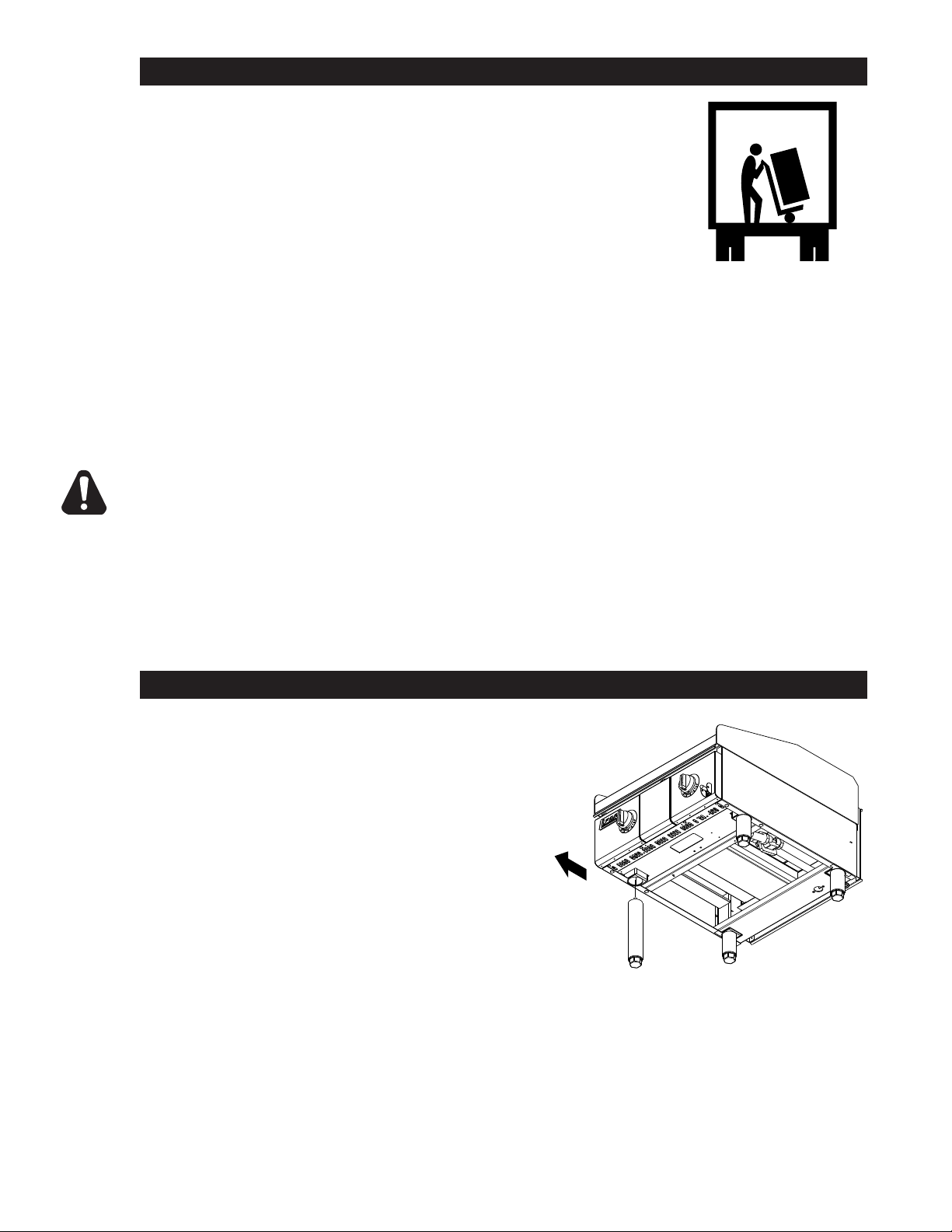
THE UNIT IS EXTREMELY HEAVY. FOR SAFE HANDLING, INSTALLER SHOULD
OBTAIN HELP AS NEEDED, OR EMPLOY APPROPRIATE MATERIALS HANDLING
EQUIPMENT (SUCH AS A FORKLIFT, DOLLY, OR PALLET JACK)
TO REMOVE THE UNIT FROM THE SKID AND MOVE IT TO THE PLACE OF
INSTALLATION.
ANY STAND, COUNTER OR OTHER DEVICE ON WHICH GRIDDLE WILL BE
LOCATED MUST BE DESIGNED TO SUPPORT THE WEIGHT OF THE GRIDDLE.
SHIPPING STRAPS ARE UNDER TENSION AND CAN SNAP BACK WHEN CUT.
LEG INSTALLATION
The legs are installed by sliding the threaded ends of the
legs into the leg receiver tubes located in each corner of
the griddle.
Slide the leg up until contact is made with the threaded
nut at the top of the reciever tube. Screw the leg counterclockwise until it is hand tight.
After the griddle is in its nal position, adjust the legs to
create 1/8 inch slant from back to front. This will allow the
grease to run into the front grease gutter and provide the
proper combustion air for the burners. It will also allow
exposed gasses to escape out the rear of the unit.
Level unit by adjusting the (4) legs for accurate and perfect
lineup with other units.
Front
IL2379
6

VENTILATION & CLEARENCE
CLEARANCE
For use on non-combustible countertops only.
Combustible and non-combustible material must be at least 48” (120cm) from the top of the
appliance. Combustible material must be 5” (150mm) from the sides and back, while clearance to
non-combustible material on the sides and back is 0”. Adequate clearance should also be provided
for proper operation and servicing.
AIR SUPPLY
Make certain not to obstruct the ow of combustion and ventilation air. Provisions for adequate air
supply must be furnished. The legs supplied with the unit must be installed. Make certain that air
intake openings in the bottom of the appliance are not obstructed. They are essential for proper
combustion and operation of the appliance.
EXHAUST CANOPY
It is essential that facilities be provided over the griddle to carry off fumes and gases. However,
the unit should not be directly connected to a ue or stack.
7
INSTALLATION
Electrical Connection
The griddle is supplied with a cord and plug. The receptacle is not provided with the griddle.
Follow the receptacle manufacturer’s instructions when connecting the receptacle to the power supply.
Gas Connection
This griddle is manufactured for use with the type of gas indicted on the nameplate.
Contact the factory if your type of gas does not match the nameplate data.
All gas connectors must be in accordance with local codes and comply with the National Fuel Federal
Gas Codes ANSI Z223.1 latest edition.
This appliance should be installed with a separate gas valve in the gas line ahead of the unit. Use a
3/4 inch or larger gas supply line.
Remove the 5/16 inch nuts securing the rear of burners. These nuts are for securing the main burners
during transportation only. The rear burner shield must be removed to gain access to the nuts.
A pressure regulator for the type of gas specied is installed on each appliance.
This regulator must be installed in the gas supply line. (Note the direction of the gas ow arrow.)
The pressure in the manifold of the appliance should be tested with a manometer and the regulator
adjusted for proper pressure with the appliance operating at full re. A 1/8 inch NPT tap is provided in
the manifold for connecting a manometer.
Correct manifold pressures are:
5 inches water column for natural gas
10 inches water column for propane
When replacing the plug in the manifold, a pipe joint compound or sealant should be used that is
resistant to the action of liquid petroleum gas.
Initial adjustments are the responsibility of the installer and are not chargeable to Lang Manufacturing
International.
After the griddle is in its nal position, adjust the legs to create 1/8 inch slant from back to front.
This will allow the grease to run into the grease gutter and provide the proper combustion air for the
burners.
DANGER: THIS APPLIANCE MUST BE GROUNDED AT THE TERMINAL
PROVIDED. FAILURE TO GROUND THE APPLIANCE COULD
RESULT IN ELECTROCUTION AND DEATH.
INSTALLATION OF THE UNIT MUST BE DONE BY PERSONNEL
QUALIFIED TO WORK WITH ELECTRICITY AND PLUMBING.
IMPROPER INSTALLATION CAN CAUSE INJURY TO PERSONNEL
WARNING
AND/OR DAMAGE TO EQUIPMENT. UNIT MUST BE INSTALLED IN
ACCORDANCE WITH ALL APPLICABLE CODES.
NOTICE: The data plate is located on the right side of the griddle. The
griddlevoltage,serialnumber,gasspecications,andclearance
specicationsareonthedataplate.Thisinformationshould
be carefully read and understood before proceeding with the
installation.
NOTICE: The installation of any components such as a vent hood, grease
extractors,reextinguishersystems,mustconformtotheir
applicable National, State and locally recognized installation
standards.
8
 Loading...