


2016.08.15. E1 user manual
User manual
Immunity development system
E 1
How to make a DUT immune to interference
through measurement and modification at the development stage
Copyright (C) Dipl.- Ing. Gunter Langer
Nöthnitzer Hang 31
01728 Bannewitz
10.04.2014

- 2 -
LANGER
EMV-Technik
DE-01728 Bannewitz
mail@langer-emv.de
www.langer-emv.de
E1
Table of contents: Page
1 Description of the E1 immunity development system 3
2 Description of the E1 components 4
2.1 SGZ 21 pulse density counter / burst generator 5
2.1.1 SGZ 21 as a disturbance generator 5
2.1.2 SGZ 21 as a pulse density counter 6
2.1.3 Preparing the SGZ 21 as a disturbance generator 6
2.1.4 Preparing the SGZ 21 as a pulse density counter and for signal monitoring 7
2.2 Field sources 8
2.2.1 Field sources for magnetic fields 8
2.2.2 Field sources for electric fields 9
2.2.3 Measurement set-up with SGZ 21 to inject burst current with field sources 11
2.3 Sensor 11
2.3.1 Principal mode of operation of the sensor 12
2.4 Magnetic field probes 13
3 The pulse density method 14
4 Prerequisites for interference suppression in a device under test 17
5 Measurement strategies for interference suppression in a device under test 17
5.1 Analysis of the interference current paths 19
5.1.1 Basic principle of magnetic coupling – two-pole injection into the DUT 19
5.1.2 Basic principle of electric coupling – single-pole injection into the DUT 24
5.2 Localisation of weak points with field sources 26
5.2.1 Mechanism of action behind magnetic field coupling 27
5.2.2 Mechanism of action behind electric field coupling 28
5.2.3 Practical procedure for coupling with magnetic field sources 29
5.2.4 Practical procedure for coupling with electric field sources 34
5.3 Monitoring of logic signals from the device under test 39
5.3.1 Use of the pulse density method to evaluate immunity levels 40
5.3.2 Monitoring of logic signals from the device under test 41
5.4 Measurement of burst-related magnetic fields 42
6 Safety instructions 44
7 Warranty 44
8 Technical specifications 45
9 Scope of delivery 46
10 Optional components 47
10.1 S2 magnetic field probe set 47
10.2 Digital or analog optical signal transmission 48

- 3 -
LANGER
EMV-Technik
DE-01728 Bannewitz
mail@langer-emv.de
www.langer-emv.de
E1
1 Description of the E1 immunity development system
The E1 immunity development system is an advanced tool for the electronics developer to examine the
immunity of modules to pulsed interference (burst/ESD) in experiments. The system allows him to analyse
the interference immunity in the confined space of a module. The selective injection of disturbance current
into individual sections (disturbance current paths) and application of pulsed electric (E fields) or magnetic
(H fields) fields to selected areas of the module's surface are decisive for the localisation of weak points.
While pulsed disturbances are applied to the device under test, the signals can be monitored
simultaneously via optical fibre without interaction.
The E1 immunity development system has been specially designed for the development process. It helps
the developer suppress interference in devices/modules or further harden them since it allows him to
clarify the immediate causes of immunity problems and test the effects of counter-measures directly.
The E1 immunity development system cannot be used for standard compliance tests. Testing a module's
immunity on the basis of the IEC 61000-4-4 and IEC 61000-4-2 standards, however, is an ideal starting point
for examining the device under test with the E1. The disturbances generated by the standard burst
generator in accordance with the standard are injected into the supply lines of the device under test and
flow back to the generator via ground. The paths on which the pulse-shaped disturbances flow through the
device module are not known. An unknown percentage of these disturbances encounters an unknown
victim in the device and generates a functional fault. This weak point can usually be pinpointed to a few
square centimetres of a module but can only be localised with difficulty in a standard compliance test. The
developer does not yet know if and where the disturbance current with its associated magnetic field
induces a voltage pulse in a conductor loop or couples electric field capacitively to sensitive lines.
Exact information about the fault pattern that has occurred is the decisive result of a failed compliance test.
But the fault pattern does not reveal precisely where the weak point of the device under test lies. A test in
accordance with the standard should thus initially be performed to determine the immunity of the device
under test so as to identify the fault pattern. The developer can then use the E1 at his workplace to analyse
the causes of the immunity problems, where the functional faults shown in the fault pattern provide a
certain orientation for interference suppression.
The immunity development system allows the developer to verify the effectiveness of EMC modifications
carried out in the interference suppression process immediately and thus to achieve a significant reduction
in the development time and development costs.

- 4 -
LANGER
EMV-Technik
DE-01728 Bannewitz
mail@langer-emv.de
www.langer-emv.de
E1
2 Description of the E1 components
The E1 immunity development system comprises a SGZ 21 pulse density / burst generator, an S31 optical
sensor, an MS 02 magnetic field probe with optical fibre output, magnetic and electric field sources and
numerous accessories.
Figure 1: E1 hardware scope of delivery.

- 5 -
LANGER
EMV-Technik
DE-01728 Bannewitz
mail@langer-emv.de
www.langer-emv.de
E1
2.1 SGZ 21 pulse density counter / burst generator
The SGZ 21 (Figure 2) is a burst generator with potential-free pulse generation on the one hand, and on the
other hand the SGZ°21 is also a pulse density counter to measure the disturbance pulses of the device
under test.
Figure 2: SGZ 21 pulse density counter / burst generator.
Generator ON/OFF: to switch the SGZ 21 on or off
Intensity: potentiometer to gradually adjust the intensity of the disturbance pulses
Pulse shape: toggle switch to change between steep and flat pulses
Counter display: six-digit counter to measure the pulse density
SIGNAL LED display: to indicate the received light signal
SPIKE LED display: to indicate the received light signal with pulse trap; the pulse is stretched to a visible
width of 50 ms
Burst output: symmetric output galvanically isolated from ground
Counter's optical fibre input: input socket for 2.2 mm plastic optical fibre
The power supply is located on the left side of the generator. A 12 V power supply unit is included in the
scope of delivery.
2.1.1 SGZ 21 as a disturbance generator
The SGZ 21 generates potential-free, pulse-shaped disturbances whose edges have a rise time of approx.
2 ns and a fall time of approx. 10 ns. In contrast, a standard generator generates pulse shapes of 5/50 ns.
The SGZ 21's smaller pulse width prevents the device under test from being destroyed. Furthermore,
working at a lower disturbance voltage level ensures greater safety for the engineer.
The SGZ 21 allows partial injection into structural parts, cables, shielding, earth connections and primarily
directly into the modules. The disturbance current of the SGZ 21 is generated via a differential output.
Consequently, the generated pulsed current does not relate to the generator housing potential.

- 6 -
LANGER
EMV-Technik
DE-01728 Bannewitz
mail@langer-emv.de
www.langer-emv.de
E1
The path that the disturbance current takes through the device under test can be defined by contacting the
device under test accordingly. Disturbance current can thus be injected into defined sections of the module
without significantly influencing the environment.
The peak values of the disturbance pulses are between 0 and 1500 volt. They are constantly changed but
are stochastically evenly distributed.
- The SGZ 21 has a symmetric output that is galvanically isolated from ground. The disturbance pulses are
coupled out capacitively with alternating polarity.
- The pulse shape toggle switch of the SGZ 21 can be used to change over between steep and flat pulses
to adjust the disturbance effect.
2.1.2 SGZ 21 as a pulse density counter
A counter with an optical input (2.2 mm plastic optical fibre) is integrated in the SGZ 21 (Figure 2). A sensor
that is located in the device under test (Chapter 0) or a magnetic field probe transmits light pulses to the
SGZ 21 counter via an optical fibre and the optical input. The received light pulses are initially displayed by
the "Signal" and the "Spike" LEDs and then counted by the counter. The counter's peak time is 1 s.
Using the pulse density method (Chapter 3) allows a very fast assessment of the sensitivity of a device
under test.
The SGZ 21 can be operated standing perpendicular on its rear so that you can easily read the counter from
above – e.g. when working standing up.
2.1.3 Preparing the SGZ 21 as a disturbance generator
Generator cables and connecting terminals are needed to operate the SGZ 21 as a disturbance generator.
The generator cables are connected to the SGZ 21 output sockets via the 4 mm plug (banana plug). The
generator cables (Figure 3) end in two-pole 0.64 mm plug pins. Both pins are connected to the core of the
cable. Only one plug pin of each generator cable is used to connect the 250 mm long extension cable
(Figure 5).
The connection to the device under test is via alligator clips or micro-kleps (miniature clamp-type test
probes with rotating grip jaws) (Figure 4). The field sources contained in the E1 system can be connected
directly to the extension cables as required.
Figure 3: Generator cables (bottom); two extension cables (top).

- 7 -
LANGER
EMV-Technik
DE-01728 Bannewitz
mail@langer-emv.de
www.langer-emv.de
E1
Figure 4: Alligator clips on the left and micro-kleps on the right.
2.1.4 Preparing the SGZ 21 as a pulse density counter and for signal monitoring
The optical fibre has to be inserted into the input up to the limit stop and fastened with the knurled screw
(Figure 6).
Figure 6: Optical fibre connection on the SGZ 21.
Figure 5: SGZ 21 with generator cables plus an alligator clip and a micro-klep.
- 8 -
LANGER
EMV-Technik
DE-01728 Bannewitz
mail@langer-emv.de
www.langer-emv.de
E1
2.2 Field sources
The field sources are supplied with disturbance current from the SGZ 21 and generate either pulsed
magnetic or electric fields depending on the type of field source used. The field intensities of these pulsed
fields are comparable to those generated by burst currents on the surface of modules during standard
compliance tests. The field sources can be used to subject small areas of the device under test or individual
conductor runs to defined disturbances.
The field sources contained in the E1 system are optimised so that they generate either a magnetic field or
an electric field. Furthermore, the field sources are of different sizes, allowing the developer to apply the
pulsed field to differently dimensioned areas on the module. In addition, there are special field sources for
specific tasks such as magnetic field sources that couple to conductors via a specially shaped field.
Different types of probe heads are offered that are designed for certain measurement tasks. They allow the
developer to pinpoint weak points to the millimetre or to search for critical links and connections such as
components, conductor runs or IC pins on the defined interference path. The sensitivity of different IC pins
can be assessed. Following localisation, the sensitive areas can be treated in a specific way.
E-field-sensitive weak points cannot be identified with H-field sources. Special E-field probes have to be
used to localise these weak points. Apart from conductor run sections, high-resistance components such as
pull-up resistors or quartz generators may also prove critical in this respect.
2.2.1 Field sources for magnetic fields
The E1 contains four field sources which are able to generate magnetic fields. Thanks to the probe head's
various designs, two types of measurements can be performed:
a) Determination of an IC pin's / conductor's sensitivity irrespective of whether a layout-related disturbance
is conducted to the IC. This measurement provides the developer with an overview of which IC pins and/or
conductor runs are sensitive in general.
b) Localisation of weak points in the layout
The disturbance fields applied from outside during the standard compliance test couple to the module's
conductor runs at weak points in the layout. The disturbances are passed on to the IC via the conductor
runs. The disturbance process triggered by the standard compliance test on the module is generally due to
electric and magnetic field coupling. The E1 system contains field sources which have been customdeveloped to simulate these field coupling phenomena for fault localisation.
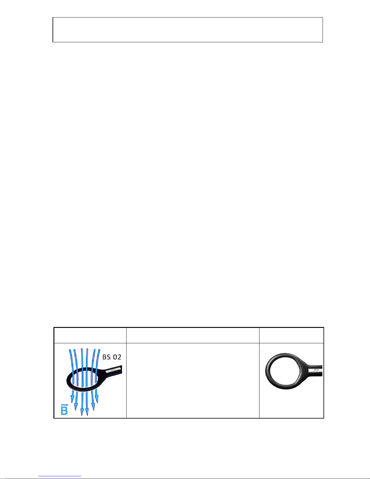
Field pattern
Use
Design
BS 02 is a field source to localise weak points in the layout. The
magnetic field source produces a B-field line bundle with a
diameter of > 5 cm. It is suitable for investigations on both
devices and modules. The size of the probe allows the developer
to apply the field to large areas of housing surfaces and inner
spaces, connecting elements and modules with conducting
structures as well as ICs to identify weak points that are sensitive
to magnetic fields.

- 9 -
LANGER
EMV-Technik
DE-01728 Bannewitz
mail@langer-emv.de
www.langer-emv.de
E1
BS 04DB is a field source to localise weak points in the layout. It
generates a B-field line bundle in the millimetre range
(approx. 3 mm). The field beam emerging from the probe's face
can be used to scan the surface of circuit boards and resolve
magnetically sensitive weak points in small spaces of 3 mm in the
field of layout and packaging. The BS°04DB allows the localisation
of critical conductor run sections, components and component
connections.
BS 05D is a field source to localise weak points in the layout. The
magnetic field source generates a B-field line bundle with a
diameter of approx. 3 mm similar to the BS 04 DB. But the field
lines are at an angle of 90° to the probe shaft. The probe is thus
ideal to localise weak points between two printed circuit boards
or in hard-to-reach locations of modules between components,
for example. Before using the BS 05D field probe, the weak point
should be roughly narrowed down with the BS 02 or BS 04DB
probe.
BS 05DU is a field source that can be used to determine an
individual IC pin's/conductor's sensitivity. The magnetic field source
generates a circular magnetic field in the millimetre range. It can
also be used as a mini coupling clamp to couple disturbance current
into selected individual conductor runs, IC pins, SMD devices and
thin lines (ribbon cable).
A module often has several insensitive and only a few sensitive
signal connections (conductor runs, IC pins). The field source is
the ideal tool to quickly identify the sensitive ones and carry out
appropriate layout modifications.
2.2.2 Field sources for electric fields
The E1 contains five field sources which are able to generate electric fields. Thanks to the probe head's
various designs, two types of measurements can be performed:
a) Determination of an IC pin's/conductor's sensitivity
b) Localisation of weak points in the layout
The size of the coupling electrode in the probe head is the field sources' distinguishing feature.
ES 08D is a probe tip that can be used to determine an
individual IC pin's/conductor's sensitivity. A galvanic isolating
point with capacitive coupling of approx. 1 pF is contained in
the probe tip which is ideal for very small structures. The
pin/conductor run is contacted with the probe tip and its
sensitivity determined by changing the intensity on the
SGZ 21 ("Intensity" controller) in the test. The field source has
to be connected via two poles. One conductor is connected to
the probe tip via a coupling capacitance of 1 pF. The second
conductor is connected to a counter-electrode, preventing
disturbance current from flowing through the device under
test unintentionally and thus affecting other areas.
Connection: two-pole
- 10 -
LANGER
EMV-Technik
DE-01728 Bannewitz
mail@langer-emv.de
www.langer-emv.de
E1
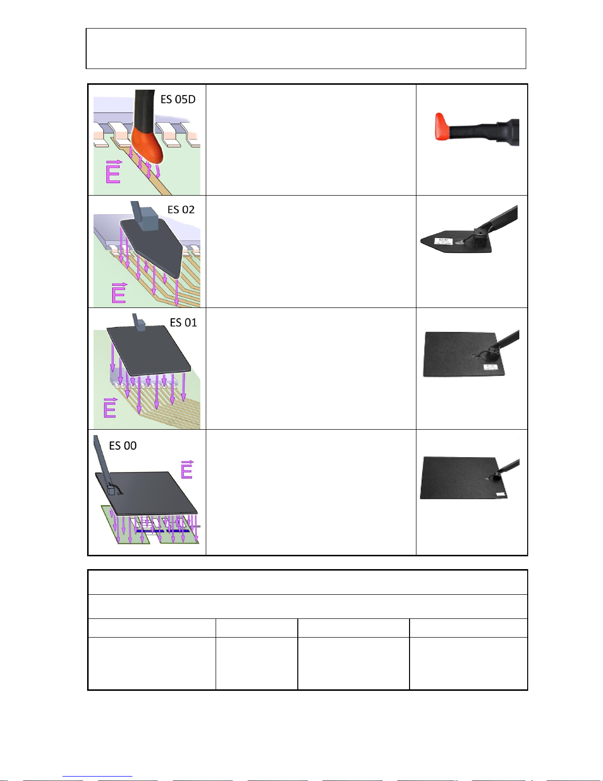
ES 05D is a field source that can be used to determine the
sensitivity of an IC pin/conductor or individual components.
The E-field source has a narrow line-shaped coupling
electrode in its probe head. This design makes it ideal for
being placed on conductor runs and small components and
their connections, wires and individual SMD components such
as resistors and capacitors. Individual plug contacts or cores
of ribbon cables can also be examined. The probe is placed on
the component/conductor run to inject the E-field.
Connection: two-pole
ES 02 is a field source to localise weak points in the layout.
The size of the field source allows the developer to couple the
field to large areas of housing surfaces and inner spaces,
connecting elements and components with conducting
structures and ICs (e.g. bus systems, LCD displays). The tip of
the E-field source can be used to localise small weak points
that are sensitive to E-field (conductor runs, quartz crystal
oscillators, pull-up resistors, ICs).
Connection: two-pole
ES 01 is a field source to localise weak points in the layout.
The field source allows electric coupling to large areas. The
probe is ideal for applying an electric field to extensive or
line-shaped weak points with a size of 5 to 10 cm and ranks
between the ES 02 and ES 00 field sources (please refer to the
corresponding description). The ES 02 may be too small and
the ES 00 source too large for certain purposes. The ES 01 can
also be used to couple disturbance current to a module. The
intensity of the disturbance current can be controlled by the
distance between the probe and the module.
Connection: single-pole
ES 00 is a field source to localise weak points in the layout.
The field source allows electric coupling to large-area or lineshaped structures (150 cm²). Electrically sensitive weak points
often extend over large areas from 10 to 15 cm of a module
(LCD display, bus systems). These weak points do not respond
to small field sources. Large-area field sources such as the
ES 00 are needed to identify this type of weak points. The
source can also be used for coupling to housings. The ES 00
can also be used to couple disturbance current to a module.
The intensity of the disturbance current can be controlled by
the distance between the probe and the module.
Connection: single-pole
Key to designations
Example: BS 04 DB
Type of field
Size
Attenuation
Special field shape
BS Field source for magnetic
field
ES Field source for electric
field
00
01
02
D Common-mode
attenuation
B Bundled field lines
U Circular field

- 11 -
LANGER
EMV-Technik
DE-01728 Bannewitz
mail@langer-emv.de
www.langer-emv.de
E1
2.2.3 Measurement set-up with SGZ 21 to inject burst current with field sources
The field sources are connected directly to the "Burst output" (Figure 2) of the SGZ 21 via the generator and
extension cables. Magnetic field sources are always connected via two poles (Figure 7).
Apart from the field sources themselves, the connecting cables also generate fields that may couple to the
device under test and affect the measurement result. Cables should thus always be kept away from the
device under test if possible.
2.3 Sensor
The S31 sensor (Figure 8) is a digital probe head to transmit binary signals from the device under test. The
sensor has a three-pin shrouded header (RM 2.5 mm). One pin of the shrouded header is the 3.5 V auxiliary
power supply. The second pin is the ground pin. The third pin is the input of the probe head. The sensor
input is connected internally to a digital IC input. This is connected to digital signals, VCC (</= 5 V) and
ground inside the device under test. The IC output supplies an optical transmitter. The transmitter is
connected to a 2 mm conical socket to accommodate a 2.2 mm plastic optical fibre (LWL). The light signals
from the sensor are transmitted to the "LWL" counter input of the SGZ 21 via an optical fibre.
The level changeover switch allows the signal to be negated.
The sensor can be used in two different ways:
a) to detect logic signals in the device under test
b) to detect disturbances in the device under test
to a) It is helpful if important signals (Reset, CE) of the device under test are monitored so as to find the
causes of problems in immunity investigations with the SGZ 21. When using a conventional oscilloscope
probe head, the disturbances are led to the oscilloscope via the probe head. The disturbances would affect
the oscilloscope. In addition, the probe head would change the disturbance current paths of the device
under test and thus falsify the measurement results. This is the reason why probe heads with an optical
fibre connection have to be used. The S31 sensor is such a probe head.
to b) The IC input of the S31 sensor has an immunity level that can be used to detect disturbances in the
device under test. The sensor's sensitivity to disturbance pulses depends on the sensitivity of the __00 IC
(four NAND gates) that is mounted on it. The user can define the sensor's sensitivity by selecting the IC to
be mounted from a certain IC family.
Figure 7: SGZ 21 with BS°04DB magnetic field source.
Depending on their type,
field sources for electric
fields are connected via one
pole or two poles (Figure 31).

- 12 -
LANGER
EMV-Technik
DE-01728 Bannewitz
mail@langer-emv.de
www.langer-emv.de
E1
Figure 8: S31 sensor with an IC mounted (top) and without IC (bottom).
Pulse stretching
Which fast transient disturbances the S31 sensor of the E1 can detect depends on the IC mounted. The
pulse widths of these disturbances may be in the nanosecond range. Due to the low limit frequency of the
optical system (5 MHz), such short disturbances cannot be transmitted. A pulse stretching circuit which
stretches short pulses to 100 ns is integrated in the sensor. The optical fibre is then able to transmit these
pulses. Neither can the optical system of the sensor transmit frequencies above 5 MHz. The same sensor
circuit reduces frequencies > 5 MHz to 5 MHz.
Without this circuit, the optical system would not be able to transmit anything. It would assume a high or low state.
The circuit ensures that fault states are transmitted from the device under test.
2.3.1 Principal mode of operation of the sensor
The sensor is integrated in the device under test and connected to the line of interest. A three-pole socket
(included in the scope of delivery) is glued to the device under test with super glue in the immediate
vicinity of the interesting signal line, if possible at the input, and wired with a short CuL wire; the ground, 35 V voltage and sensor input are also wired before the sensor is connected (Figure 9). The wiring should be
short and laid directly on the module's surface so as to prevent the formation of loops where magnetic or
electric fields could couple in.
The S31 sensor is supplied with a 3 to 5 volt voltage from the device under test. If this is not possible, a
battery module can be used (not included in the scope of delivery).
Figure 9: S31 sensor connected to an IC in the device under test, for example, via a three-pole socket.
ICs which have been damaged
during the measurement can be
easily replaced.

- 13 -
LANGER
EMV-Technik
DE-01728 Bannewitz
mail@langer-emv.de
www.langer-emv.de
E1
2.4 Magnetic field probes
The magnetic field probe is used to measure burst-related magnetic fields in the device under test.
The disturbance current i of the SGZ 21 generates a magnetic field B. The magnetic field which penetrates
the probe head induces a voltage in the probe head's induction coil. The voltage drives an optical
transmitter diode that is located in the MS 02 probe shaft (Figure 10).
Each disturbance pulse of the SGZ 21 causes a light pulse of the optical transmitter diode. The transmitter
diode has a 2.2 mm conical socket and is integrated in the MS 02 probe shaft. An optical fibre is guided
from the rear end of the MS 02 probe shaft through to the socket of the transmitter diode. The light pulse
is transmitted to the SGZ 21 in the same way as with the S31 sensor (Chapter 2.3). The measurement of the
magnetic field is based on the pulse density method (Chapter 3).
Figure 10: Measuring a magnetic field with the MS 02 probe.
Fields which penetrate the probe's induction coil in the orthogonal direction induce a voltage. Fields whose
direction coincides with the coil plane do not induce a voltage and are thus not detected. The maximum
voltage corresponds to the direction of the magnetic field (Figure 11). The MS 02 magnetic field probe is
used to determine the field distribution. The probe emits a light pulse for each magnetic field pulse which is
detected. The value shown on the SGZ 21 counter is proportional to the mean magnetic field strength
measured (Chapter 3, pulse density method). The field line configuration and field density are indicative of
the disturbance current distribution in the device under test.
The MS 02 is a passive probe and does not require any auxiliary power. The power needed to generate the
light pulses is taken from the burst-related magnetic field. The MS 02 is connected to the SGZ 21 counter
input via an optical fibre.
Figure 11: The MS 02 magnetic field probe can detect a magnetic field which is orthogonal to the probe
opening/probe shaft.

- 14 -
LANGER
EMV-Technik
DE-01728 Bannewitz
mail@langer-emv.de
www.langer-emv.de
E1
3 The pulse density method
The pulse density method is a measuring method which can be used to determine the relative immunity of
a device under test. The effect of EMC modifications can be evaluated based on the relative immunity.
Furthermore, the pulse density method is the basis for measuring burst-related magnetic fields with MS 02
magnetic field probes and the optional S2 magnetic field measuring system (Chapter 10).
Figure 12: Ramp-like rise of the SGZ 21 disturbance pulses. The immunity level is exceeded n times at
different immunity level voltages u.
Figure 12 shows how the pulse density method functions in principal. The voltage u of the disturbance
pulses gradually rises from a minimum value to a maximum value up a ramp over the time T = 1 s. This
process is continuously repeated.
If the disturbance pulses encounter an immunity level u1 in the device under test, the disturbance pulses
which are greater than u1 will exceed the immunity level u1. This is n = 11 pulses in the example. If the
device under test has a higher immunity level, u3, for example, n = 3 pulses will exceed the immunity level.
The number of pulses which exceed the immunity level is inversely proportional to the value of the
immunity level.
This principle can be implemented with the E1 components, i.e. the SGZ 21 and the S31 sensor or the
MS 02 magnetic field probe.
The SGZ 21 generates disturbance pulses which are injected into the device under test. The S31 sensor is
used to create an immunity level in the device under test. If the immunity level of the S31 sensor is
exceeded, a light pulse is transmitted to the SGZ 21 counter via optical fibre. The counter counts how often
the immunity level is exceeded. Depending on the immunity level, the value in the aforementioned
example is: n = 3, n = 7, n = 11. These values are proportional to the immunity of the device under test
relative to the immunity level of the sensor.
This means: the immunity of the device under test is high at n = 3 and the immunity of the device under
test is low at n = 11.
The pulses that are counted in practice may be in the range between 0 and 3,000. A low value is indicative
of a high immunity while a higher value is indicative of a low immunity.

- 15 -
LANGER
EMV-Technik
DE-01728 Bannewitz
mail@langer-emv.de
www.langer-emv.de
E1
There are two possibilities of creating an immunity level with the S31 sensor in the circuitry of a device
under test.
Figure 13: Artificial magnetic field immunity level established by mounting the S31 sensor with
enamelled copper wire as a simulated conductor run.
Figure 13 shows the simulation of a signal conductor run with enamelled copper wire. The enamelled
copper wire is connected to ground on one side and to the input of the S31 sensor on the other. The SGZ 21
is connected to the device under test via two poles. The disturbance pulses i
Stör
from the SGZ 21 penetrate
the device under test and generate a burst-related magnetic field B. The burst-related magnetic field
induces a disturbance voltage in the inserted enamelled copper wire loop which becomes effective on the
S31 sensor input. A light pulse is triggered when the immunity level of S31 is exceeded.
Figure 14: Artificial electric field immunity level established by mounting the S31 sensor with enamelled
copper wire as a simulated conductor run.
Figure 14 shows the simulation of a signal conductor run with enamelled copper wire. The enamelled
copper wire is connected to a pull-up resistor on one side and to the S31 sensor input on the other. The
SGZ 21 is connected to the device under test via one pole. An electric field is generated at the surface of the
device under test. The electric field couples capacitively to the enamelled copper wire and generates a
disturbance voltage on the S31 sensor input. A light pulse is triggered when the immunity level of S31 is
exceeded.
 Loading...