

Page 1
Installation
Operation
Maintenance
Troubleshooting
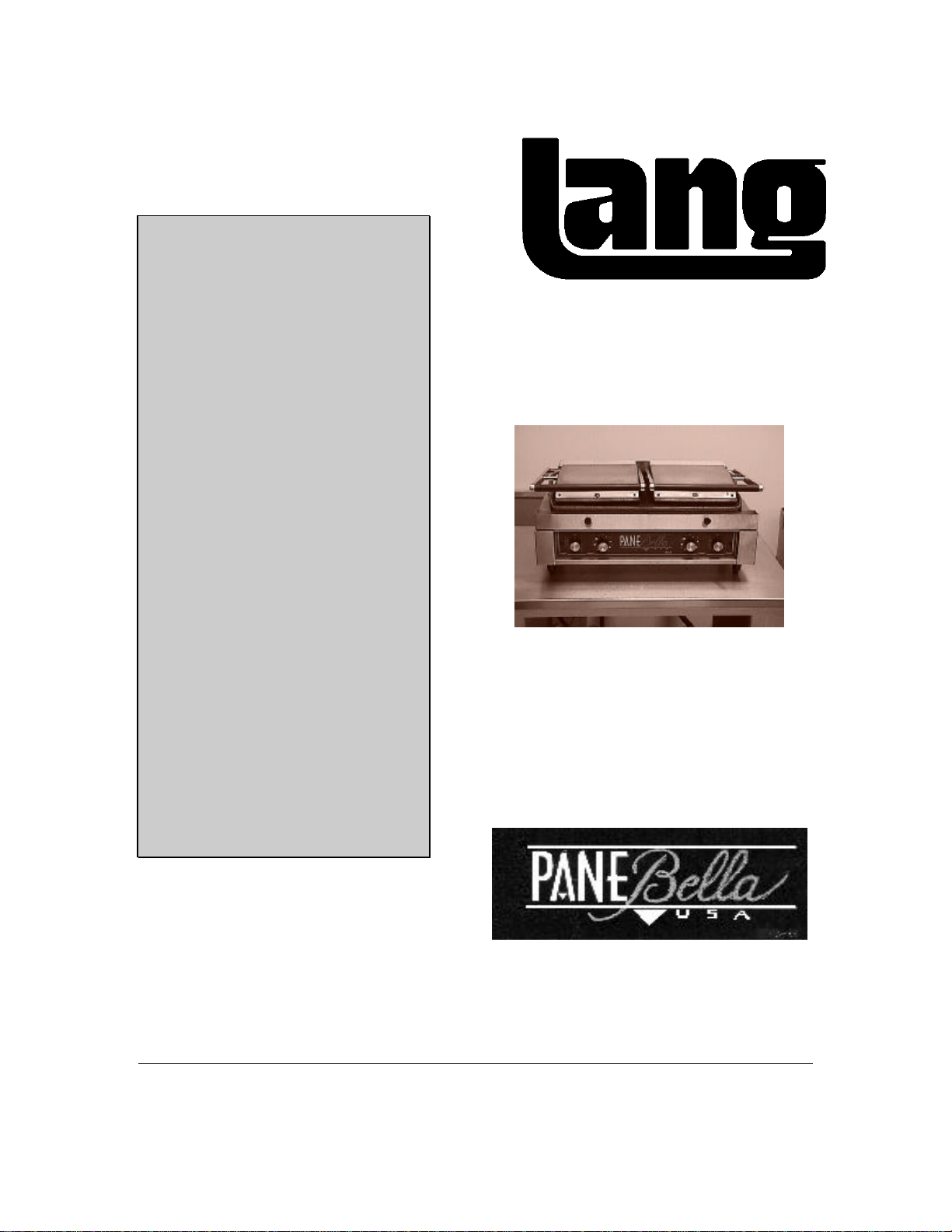
Model: PANE
BELLA
USA-24-6
Lang Manufacturing Company 6500 Merrill Creek Parkway Everett, WA 98203
Part Number: 60800-34 Phone: 425-349-2400 Fax: 425-349-2733 © Copyright 1997
WWW.LANGWORLD.COM
Page 2

THIS MANUAL MUST BE RETAINED FOR FUTURE REFERENCE.
READ, UNDERSTAND AND FOLLOW THE INSTRUCTIONS AND
WARNINGS CONTAINED IN THIS MANUAL.
2
Page 3

1. TABLE OF CONTENTS
CHAPTER PAGE
1. TABLE OF CONTENTS......................................................................3
2. OPERATOR WARNINGS (READ FIRST) ............................................4
3. EQUIPMENT DESCRIPTION..............................................................6
4. UNPACKING......................................................................................7
5. INSTALLATION.................................................................................8
6. INITIAL START-UP ............................................................................10
7. OPERATION.....................................................................................11
8. CLEANING & MAINTENANCE PROCEDURES....................................16
9. TROUBLESHOOTING........................................................................18
10. PARTS LISTS....................................................................................20
11. WIRING DIAGRAMS..........................................................................21
12. WARRANTY …………………………………………………………………..22
3
Page 4
2. WARNINGS
IMPORTANT READ FIRST IMPORTANT
DO NOT STORE OR USE GASOLINE OR OTHER FLAMMABLE VAPORS
AND LIQUIDS IN THE VICINITY OF THIS OR ANY OTHER APPLIANCE.
WARNING: IMPROPER INSTALLATION, ADJUSTMENT, ALTERATION,
SERVICE OR MAINTENANCE CAN CAUSE PROPERTY DAMAGE,
INJURY OR DEATH. READ THE INSTALLATION, OPERATING AND
MAINTENANCE INSTRUCTIONS THOROUGHLY BEFORE INSTALLING
OR SERVICING THIS EQUIPMENT.
DANGER:
WARNING:
1.) THIS APPLIANCE MUST BE GROUNDED AT THE TERMINAL
PROVIDED. FAILURE TO GROUND THE APPLIANCE COULD
RESULT IN ELECTROCUTION AND DEATH.
1.) INSTALLATION OF THIS LANG CONVECTION OVEN MUST BE DONE
BY PERSONNEL QUALIFIED TO WORK WITH ELECTRICITY.
IMPROPER INSTALLATION CAN CAUSE INJURY TO PERSONNEL
AND/OR DAMAGE TO THE EQUIPMENT. THE UNIT MUST BE
INSTALLED IN ACCORDANCE WITH ALL APPLICABLE CODES.
2.) ALWAYS KEEP THE AREA NEAR THE APPLIANCE FREE FROM
COMBUSTIBLE MATERIALS.
3.) BEFORE PERFORMING ANY WORK ON INTERNAL COMPONENTS,
DISCONNECT THE APPLIANCE FROM THE ELECTRIC POWER
SUPPLY.
4.) KEEP WATER AND SOLUTIONS OUT OF CONTROL AND
ELECTRICAL EQUIPMENT. NEVER SPRAY WATER ON THE
APPLIANCE WHICH MAY PERMIT LIQUID TO GET INTO THE
CONTROL AND ELECTRICAL EQUIPMENT AREAS.
4
Page 5

2. WARNINGS CONT’D
CAUTION:
1.) KEEP FLOOR IN FRONT OF EQUIPMENT CLEAN AND DRY. IF
SPILLS OCCUR, CLEAN IMMEDIATELY, TO AVOID THE DANGER OF
SLIPS OR FALLS.
2.) MOST CLEANERS ARE HARMFUL TO THE SKIN, EYES, MUCOUS
MEMBRANES AND CLOTHING. PRECAUTIONS SHOULD BE TAKEN
TO WEAR RUBBER CLOVES, GOGGLES OR FACE SHIELD AND
PROTECTIVE CLOTHING. CAREFULLY READ THE WARNING AND
FOLLOW THE DIRECTIONS ON THE LABEL OF THE CLEANER TO
BE USED.
3.) USE OF ANY REPLACEMENT PARTS OR OTHER THAN THOSE
SUPPLIED BY LANG OR THEIR AUTHORIZED DISTRIBUTOR CAN
CAUSE BODILY INJURY TO THE OPERATOR AND DAMAGE TO THE
EQUIPMENT AND WILL VOID ALL WARRANTIES.
4.) BE SURE ALL OPERATORS READ, UNDERSTAND AND FOLLOW
THE OPERATING INSTRUCTIONS, CAUTIONS AND SAFETY
INSTRUCTIONS CONTAINED IN THIS MANUAL.
5.) SHIPPING STRAPS ARE UNDER TENSION AND CAN SNAP BACK
WHEN CUT.
6.) UNIT IS EXTREMELY HEAVY. FOR SAFE HANDLING, INSTALLER
SHOULD OBTAIN HELP AS NEEDED, OR EMPLOY APPROPRIATE
MATERIALS HANDLING EQUIPMENT (SUCH AS A FORKLIFT,
DOLLY, OR PALLET JACKET) TO REMOVE THE UNIT FROM THE
SKID AND MOVE IT TO THE PLACE OF INSTALLATION.
NOTICE:
IMPORTANT:
1.) NEVER LEAVE A CHLORINE SANITIZER IN CONTACT WITH
STAINLESS STEEL SURFACES LONGER THAN 10 MINUTES.
LONGER CONTACT CAN CAUSE CORROSION.
1.) SERVICE PERFORMED BY OTHER THAN FACTORY AUTHORIZED
PERSONNEL WILL VOID ALL WARRANTIES.
5
Page 6
3. EQUIPMENT DESCRIPTION
Lang Model: USA-24-6
PANE BELLA GRIDDLE
3.1 Exterior Construction
• The griddle dimensions are 12.25” (31.12cm) High (allow an additional 13” (33.02cm
for upper element swing), 14” (35.56cm) Deep, and 24” (60.96) wide.
• The griddle surface is made of two upper and one lower gray iron casting griddle
surfaces.
3.2 Operation
• Each twelve-inch section has its own thermostat and timer.
3.3 Controls
• The PANE BELLA Griddle comes with controls which include:
∗ An independently controlled thermostat for each section.
∗ A separate timer for each section.
3.4 Technical
• Griddle operates on 208, 220, or 240 Volts. It is shipped with a Power Cord and Plug
attached.
• Counter space required is 14” (35.56cm) Deep, and 24” (60.96) wide.
• The griddle weighs 130 lbs.
3.5 Ventilation and Clearances
Standard minimum clearance from combustible construction is as follows:
1 inches from sides
4 inches from back
1 inches from floor
3.6 Electrical Specifications
ELECTRICAL SPECIFICATIONS
Model
Number
USA-24-6
Volt
208 3240 15.58 12 GA
220 3625 16.48 12 GA
240 4314 17.98 12 GA
Watts Amps Wire
6
Page 7

4. UNPACKING
CAUTION
4.1 Receiving the Griddle
Upon receipt, check for freight damage, both visible and concealed. Visible damage
should be noted on the freight bill at the time of delivery and signed by the carrier's
agent. Concealed loss or damage means loss or damage which does not become apparent
until the merchandise has been unpacked. If concealed loss or damage is discovered
upon unpacking, make a written request for inspection by the carrier's agent within 15
days of delivery. All packing material should be kept for inspection. Do not return
damaged merchandise to Lang Manufacturing Company. File your claim with the
carrier.
4.2 Location
Prior to un-crating, move the griddle as near its intended location as practical. The
crating will help protect the unit from the physical damage normally associated with
moving it through hallways and doorways.
4.3 Un-crating
The griddle will arrive completely assembled inside a wood frame covered by cardboard
box and strapped to a skid. Remove the cardboard cover, cut the straps and
remove the wood frame.
GRIDDLE WEIGHS 130 LBS (64.68 kilograms). FOR SAFE HANDLING
INSTALLER SHOULD OBTAIN HELP AS NEEDED OR EMPLOY
APPROPRIATE HANDLING EQUIPMENT TO REMOVE GRIDDLE FROM
SKID.
CAUTION
ANY STAND, COUNTER OR OTHER DEVICE ON WHICH GRIDDLE WILL BE
LOCATED MUST BE DESIGNED TO SUPPORT THE WEIGHT OF THE
GRIDDLE (130LBS).
Remove griddle from skid and place in intended location.
7
Page 8

5. INSTALLATION
CAUTION
DANGER
THIS APPLIANCE MUST BE GROUNDED AT THE TERMINAL PROVIDED.
FAILURE TO GROUND THE APPLIANCE COULD RESULT IN
ELECTROCUTION AND DEATH.
The data plate is located on the back of the griddle. The griddle voltage,
wattage, serial number, wire size, and clearance specifications are on the
data plate. This information should be carefully read and understood
before proceeding with the installation.
NOTICE
The installation of any components such as a vent hood, grease extractors, fire
extinguisher systems, must conform to their applicable Nationally recognized
installation standards.
5.1 Electrical Connection
The oven is supplied with a cord and plug connected. The plug provided is a NEMA-L630P.
Follow the receptacle manufacturer’s instructions when connecting the receptacle to the
power supply.
The electrical connection must be made in accordance with local codes or in the absence
of local codes with NFPA No. 70 latest edition (in Canada use: CSA STD. C22.1).
The electrical service entrance is provided by a cord and plug located at the rear of the
appliance.
The plug provided with the grill is a L6-30P. The receptacle must be supplied by the
installer and is a L6-30R.
Supply wire size must be large enough to carry the amperage load for the number of
appliances being installed. Wire size information can be found on the data
plate and on the chart below.
ELECTRICAL SPECIFICATIONS
Model
Number
USA-24-6
Volt
208 3240 15.58 12 GA
220 3625 16.48 12 GA
240 4314 17.98 12 GA
Watts Amps Wire
8
Page 9

5. INSTALLATION CONT’D
5.2 Ventilation and Clearances
Standard minimum clearance from combustible construction is as follows:
1 inches from sides
4 inches from back
1 inches from floor
The installation of any components such as a vent hood, grease extractors, and/or fire
extinguisher systems, must conform to the their applicable nationally recognized
installation standards.
9
Page 10

6. INITIAL START UP
6.1 Initial Start Up
Before starting the grill for the first time, clean the grill body and cooking surfaces with a
mild soap and water solution then rinse with clear water and dry.
Close the upper cooking surface and turn the temperature dial to position number 1 for 2
hours to evaporate any moisture that may be in the elements and grill castings.
After 2 hours, turn the temperature dial to position 4 for 1/2 hour.
The grill may emit a small amount of smoke as the cooking surfaces passes the 300
degree point. Do not be alarmed, as the smoke is caused by oils associated with the
manufacturing process, and will stop when the grill reaches 350 degrees.
6.2 Seasoning the Cooking Surfaces
The cooking surfaces must be "seasoned" in order to eliminate product sticking.
To season, set the dial to position 2.
Once at temperature (the indicator lamp will go Off), spray the upper and lower
cooking surfaces with a non-salted vegetable oil such as Pam.
Allow the grill to stand at temperature until the cooking surfaces look dry then spray
them again.
Turn the temperature dial to position number 4 and wait until the indicator lamp goes out
then repeat the procedure.
10
Page 11

7. OPERATION
7.1 Setting the Temperature
The grill is divided into a left and right cooking section with upper and lower cooking
surfaces.
A single thermostat controls each section's upper and lower cooking surface.
The temperature range of each thermostat is approximately 100 to 650 degrees
Fahrenheit, Number 1 on the dial equals approximately 200 degrees, 7 equals
approximately 650 degrees.
To set the temperature, turn the thermostat dial until the line on the knob is pointing
at the desired number.
Close the upper cooking surface during preheat and idle periods.
An indicator lamp next to the thermostat dial will glow until the cooking surfaces reach
the set temperature. Once at the set temperature, the indicator lamp will go Off.
CONSERVATION HINT:
Close the upper cooking surfaces during preheat and idle times. The grill
will require far less energy to remain at temperature.
7.2 Setting the Timers
Each cooking section has a 15 minute timer.
To set the timer, turn the timer dial past 10 then back until the line on the knob is pointing
at the desired time.
The timer will sound a single ring when the timer has counted down to zero.
The timer does not control the cooking section.
7.3 Loading the grill
Open the upper cooking surface by raising the handle to the full up position.
Place the product in the center of the lower cooking section.
Grasp the handle of the upper cooking surface and gently lower it onto the product.
Set the timers for the desired cooking time.
When the bell sounds, raise the upper cooking surface and remove the product.
Clean the upper and lower cooking surfaces, with the Pane Bella cleaning tool, between
each load.
7.4 Suggested Times and Temperatures
The Panini Sandwich cooks at temperature dial position number 5 for approximately 3
minutes depending on the bread. We suggest a porous Focaccia bread.
11
Page 12

7. OPERATION CONT’D
7.5 MENU SUGGESTIONS
Ingredients Measure Average Cost*
I. Fresh Mozzarella 2 oz. .36
Tomatoes 2 oz. .10
Fresh Sweet Basil 1/2 oz. .08
Focaccia Bread .50
II. Prosciutto 2 oz .37
Fontina Cheese 2 oz .22
Tomatoes 2 oz .10
Fresh Sweet Basil 1/2 oz .08
Roasted Red Peppers 1 oz. .15
Focaccia Bread .50
*Total: 1.42
III. Grilled Eggplant 2 oz .34
Fontina Cheese 2 oz .22
Tomatoes 2 oz .10
Fresh Sweet Basil 1/2 oz. .08
Focaccia Bread .50
*Total: 1.24
12
*Total: 1.04
Page 13

7. OPERATION CONT’D
IV. Smoked Turkey 2 oz .36
Havarti 1 oz .20
Mozzarella 1 oz .10
Red Onion Reds 1/8 oz .05
Tomatoes 2 oz .10
Fresh Sweet Basil 1/2 oz .08
Focaccia Bread .50
V. Ham 2 oz .32
Mozzarella Cheese 1 oz .10
Fontina Cheese 1 oz .11
Tomatoes 2 oz .10
Sweet Basil 1/2 oz .08
Focaccia Bread .50
*Total: 1.21
VI. Marinated Artichokes 1 oz. .14
Provolone 2 oz. .22
Red Onion Rings 1/8 oz .05
Tomatoes 1 oz .05
Roasted Red Peppers 1 oz .15
Fresh Sweet Basil 1/2 oz .08
Focaccia Bread .50
*Total: 1.19
13
*Total 1.39
Page 14

7. OPERATION CONT’D
VII. Breakfast Bagel or Muffin
Turkey or Ham 1 oz .17
Provolone or Cheddar 1 oz .11
Bagel / Muffin .15
*Total: 0.43
VIII. Dessert Panini
Combine Ricotta Cheese and Powder
Sugar
Chocolate Chip 1 oz .19
Fresh Sliced Peaches / Strawberries
or Blackberries
Focaccia Bread 1/2 Slice .25
Garnish With Whipped Cream
*Total: 1.21
* These are estimated costs, your costs may vary.
Split Focaccia bread length wise (horizontally). Optional brushing inside of cut surfaces
with seasoned olive oil (soak crushed garlic cloves in 2 cups of olive oil, add 1 teaspoon
white pepper and 1 teaspoon dried crushed oregano leaves. Marinate mixture for at least
4 days.)
Build sandwiches and cut into wedges, wrap in clear wrap and refrigerate until needed.
Panini sandwiches are as individual as you are. Enjoy exercising your imagination!!
Meats
Prosciutto Pepperoni
Salami Smoked Turkey
Pastrami Mortadella
Braesala Pancetta
Capacolla Italian Sausage
Sopressata Chicken
Black forest Ham
14
2 oz. .36
2 oz .41
Page 15

7. OPERATION CONT’D
Cheeses
Cambozola Bel Paese
Smoked Cheddar Morbier
Taleggio Mozzarella
Cacciocavallo Gorgonzola
Provolone Creamy Havarti
Swiss Fontina
Vegetables
Roasted red pepper Sun dried Tomatoes
Marinated Artichoke hearts Roasted Eggplant
Red Onion Green peppers
Fresh Spinach Fresh Tomatoes
Fresh sweet Basil Mushrooms
Pepperoncini Parsley
Cilantro
Breads
Focaccia French Rolls
Sour Dough Foccacia Sour Dough
Par Baked Pizza Dough Boboli®
Baquett Bagels
English Muffins
NOTE: IT IS BEST TO USE TRUE FOCACCIA BREAD WHICH IS LIGHT AND
POROUS. HEAT PENETRATES THE SANDWICH EASIER WHEN THE
BREAD IS PARTIALLY COOKED RATHER THAN FULLY COOKED, CRUSTY
AND DARK.
15
Page 16

9. MAINTENANCE & CLEANING
8.1 Cleaning
WARNING
TO PREVENT THE UPPER GRILL FROM FALLING CLOSED WHILE
CLEANING, ALWAYS USE THE HANDLE TO HOLD THE UPPER GRILL IN
THE OPEN POSITION.
The grill is supplied with a Pane Bella grill cleaning tool. Clean the upper and lower
cooking surfaces, with the tool, between each load.
WARNING
DO NOT USE ICE OR WATER TO CLEAN THE COOKING SURFACE WHEN
THE GRILL IS HOT. THE SURFACES ARE CAST IRON AND MAY CRACK
UNDER THE SHOCK OF RAPID TEMPERATUE CHANGE.
For more stubborn buildups on the cooking surfaces use one of the commercially
available liquid cleaners for grills. Follow the manufactures instructions for use.
Clean the exterior of the grill with a mild soap and water solution to maintain a gleaming
appearance.
Empty the crumb tray regularly. It is removable and located at the front edge of the grill.
8.2 Component Access
The thermostats, timers, indicator lamps, power cord and lower cooking surface heating
elements are located inside the body of the grill. Access to these components is achieved
through the bottom of the unit. Gently tip the entire grill onto its side and remove the
four screws holding the bottom to the body. Take care not to damage the power cord
exiting the rear of the grill.
The upper surface heating elements are located in the upper grill assembly. To access,
remove the four screws and one knob holding the curved cover onto the upper assembly.
The upper cooking surface assist springs are located at the top rear of the unit under the handle pilot cover.
To access, remove one screw located at the back of the cover then slide the cover to one side.
16
Page 17

8. MAINTENANCE & CLEANING CONT’D
8.3 Thermostat Calibration
CAUTION
GRILL CALIBRATION RQUIRES DISASSEMBLY OF THE THERMOSTAT
AND SHOULD BE PERFORMED BY QUALIFIED PERSONNEL ONLY. IT IS
GENERALLY MORE COST EFFECTIVE TO REPLACE A THERMOSTAT
THAT IS OUT OF CALIBRATION.
The grill temperature will vary by as much as 50 degrees from the bottom to the top of
the groove. Take all temperatures at the bottom of the groove.
Allow the grill to operate at temperature for 1 hour before attempting to check the
calibration.
Place a surface thermometer in the center of each lower cooking section at the bottom
of the groove.
Record the temperatures at which the thermostat indicator lamp just turns On then Off,
disregard any temperatures other than On and Off.
Average the On and Off temperatures, if the temperature average is within 25 degrees of
the set temperature the thermostat need not be replaced.
17
Page 18

9. TROUBLESHOOTING
9.1 Symptoms
What follows is a chart of Symptoms and Possible Causes to aid in diagnosing faults with
the griddle.
Refer to the Symptoms column to locate the type of failure then to the Possible Cause for
the items to be checked.
To test for a possible cause refer to the TEST section and locate the Possible Cause then
refer to test to identify test procedures.
SYMPTOM POSSIBLE CAUSE
Hood not getting hot
Section will not heat
Product burning
Product under done
Heat lamp doesn’t light
• Failed element
• Failed element
• Failed thermostat
• Product is cooked too long
• Failed thermostat
• Failed thermostat
• No power
• Failed thermostat
• Failed pilot light
• Failed element
18
Page 19

9. TROUBLESHOOTING CONT’D
9.2 TESTS
WARNING
SERVICE ON THIS, OR ANY OTHER, LANG APPLIANCE MUST BE
PERFORMED BY QUALIFIED PERSONNEL ONLY. CONSULT YOUR
AUTHORIZED SERVICE STATION DIRECTORY OR CALL THE FACTORY
AT 1-800-224-LANG (5264), OR WWW.LANGWORLD.COM FOR THE
SERVICE STATION NEAREST YOU.
BOTH HIGH AND LOW VOLTAGES ARE PRESENT INSIDE THIS
APPLIANCE WHEN THE POWER SWITCH IS ON OR OFF. THIS
APPLIANCE MUST BE REMOVED FROM ALL SOURCES OF POWER PRIOR
TO PERFORMING SERVICE ON THE APPLIANCE
POSSIBLE CAUSE TEST
Product not being removed when timer
sounds
No power
Failed pilot light
Failed element
• No test available, operational condition
• Check for correct incoming voltage
• Ensure circuit breaker is not tripped
• Check for continuity across pilot light leads
• Remove the wires from the element terminals and
check for continuity across the element
19
Page 20

10. PARTS LIST
DESCRIPTION PART #
Element, Lower, 900 Watt..............................................................11030-40
Element, Upper, 720 Watt ..............................................................11030-41
Stud, Grill Plate, 10-24 x 1..............................................................20101-13
Stud, Grill Plate, 10-24 x 1 1/4........................................................20101-14
Screw, Crumb Tray Knob ...............................................................20101-24
Thermostat 650°............................................................................30402-36
Terminal Strip................................................................................30500-03
Timer 15 min..................................................................................30801-02
Terminal, Wire, Ring........................................................................................ 31001-03
Terminal, Power Cord......................................................................................31001-04
Terminal, Wire, 1/4 Inch Flag...........................................................................31005-01
Wire, 18 Gage, Black.......................................................................................31001-04
Wire, 18 Gage, Red......................................................................................... 31001-06
Wire, 16 Gage, High Temp.............................................................................. 31103-01
Lamp, Indicator................................................................................................ 31601-01
Crumb Tray, with Knobs.................................................................................. 50302-27
Plate, Grill, Lower............................................................................................ 50800-78-2
Plate, Grill, Upper Left..................................................................................... 50800-79-1
Plate, Grill, Upper Right................................................................................... 50800-80-1
Spring, Upper Grill Assist.................................................................................51001-31
Cord & Plug, Power Cord................................................................................ 60102-161
Label, Panel.....................................................................................................60301-99
Diagram, Wiring...............................................................................................61114-33
Knob, Crumb Tray...........................................................................................70701-49
Knob, Thermostat............................................................................................70701-53
Knob, Timer.....................................................................................................70701-54
Bushing, Strain Relief, Power Cord.................................................................70801-21
Leg, 3 inch.......................................................................................................72500-11
Cleaning Tool, Pane Bella............................................................................... PB-901
20
Page 21

Page 22

THIS PAGE IS INTENTIONALLY LEFT BLANK
22
Page 23

Lang
Manufacturing
Limited
Warranty to
Commercial
Lang Manufacturing Equipment (“Lang Equipment”) has been skillfully
manufactured, carefully inspected and packaged to meet rigid standards
of excellence. Lang warrants its Equipment to be free from defects in
material and workmanship for (12) twelve consecutive months, with the
following conditions and subject to the following limitations.
I. This parts and labor warranty is limited to Lang Equipment sold to the
original commercial purchaser/users (but not original equipment
manufacturers), at its original place of installation, in the continental
United States, Hawaii and Canada.
Purchasers*
(Domestic U.S., Hawaii, &
Canadian Sales only.)
Quartz elements are warranted for ninety(90) days from the date of
installation.
II. Damage during shipment is to be reported to the carrier, is not
covered under this warranty, and is the sole responsibility of
purchaser/user.
III. Lang, or an authorized service representative, will repair or replace,
at Lang’s sole election, and Lang Equipment, including but not limited
to, safety valves, gas and electric components, found to be defective
during the warranty period. As to warranty service in the territory
described above, Lang will absorb labor and portal to portal
transportation costs (time & mileage) for the first (12) twelve months
from the date of installation or eighteen (18) months from date of
shipment from Lang Manufacturing, which ever comes first.
IV. This warranty does not cover routine general maintenance, periodic
adjustments, as specified in operating instructions or manuals, and
consumable parts such as quartz elements, or labor costs incurred for
removal of adjacent equipment or objects to gain access to Lang
Equipment. This warranty does not cover defects caused by improper
installation, abuse, careless operation, or improper maintenance of
equipment.
V. THIS WARRANTY IS EXCLUSIVE AND IS IN LIEU OF ALL
OTHER WARRANTIES, EXPRESSED OR IMPLIED, INCLUDING
ANY IMPLIED WARRANTY OF MERCHANTABILITY OR
FITNESS FOR A PARTICULAR PURPOSE, EACH OF WHICH IS
HEREBY EXPRESSLY DISCLAIMED. THE REMEDIES
DESCRIBED ABOVE ARE EXCLUSIVE AND IN NO EVENT
SHALL LANG BE LIABLE FOR SPECIAL, CONSEQUENTIAL OR
INCIDENTAL DAMAGES FOR THE BREACH OR DELAY IN
PERFORMANCE OF THIS WARRANTY.
VI. Lang Equipment is for commercial use only. If sold as a component
of another(OEM) manufacturer’s equipment, or if used as a consumer
product, such Equipment is sold AS IS and without any warranty.
23
 Loading...