

Page 1
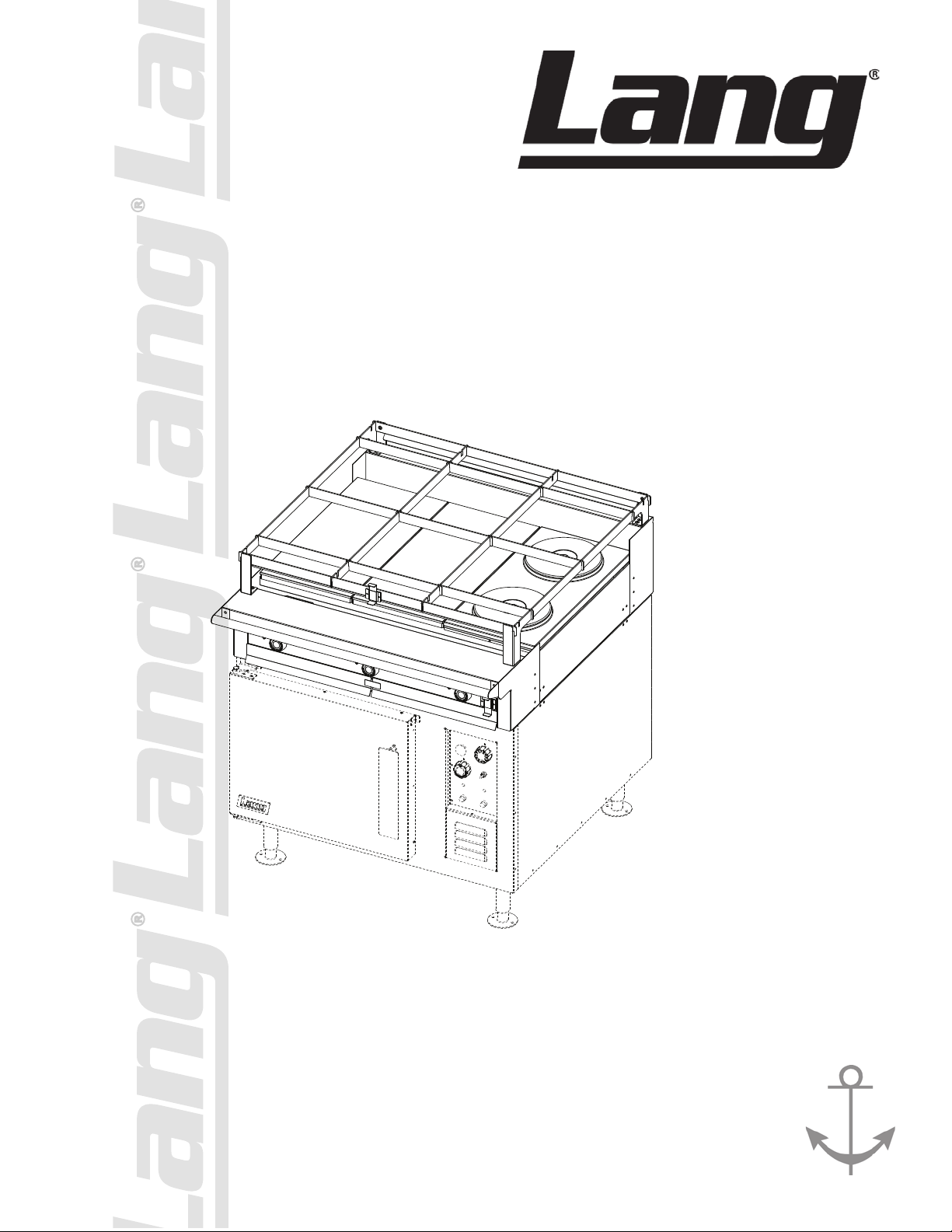
ELECTRIC RANGE
IL1362
RT36
TOP
RT36A thru RT36G
RTI36
Installation and
Operation
Instructions
2M-W1091 Rev. F 10/4/12
FCOF-AT
Page 2
2M-W1091, Commerical & Marine Electric Range Top
These symbols are intended to alert the user to the presence of
important operating and maintenance instructions in the manual
accompanying the appliance.
FOR YOUR SAFTEY
DO NOT STORE OR USE GASOLINE OR OTHER FLAMMABLE VAPORS AND LIQUIDS IN
THE VICINTIY OF THIS OR ANY OTHER APPLIANCE.
POST IN PROMINENT LOCATION
INSTRUCTIONS TO BE FOLLOWED IN THE EVENT USER SMELLS GAS. THIS
INFORMATION SHALL BE OBTAINED BY CONSULTING YOUR LOCAL GAS SUPPLIER.
AS A MINIMUM, TURN OFF THE GAS AND CALL YOUR GAS COMPANY AND YOUR
AUTHORIZED SERVICE AGENT. EVACUATE ALL PERSONNEL FROM THE AREA.
WARNING
IMPROPER INSTALLATION, ADJUSTMENT, ALTERATION, SERVICE OR MAINTENANCE
CAN CAUSE PROPERTY DAMAGE, INJURY OR DEATH. READ THE INSTALLATION,
OPERATION & MAINTENANCE INSTRUCTIONS THOROUGHLY BEFORE INSTALLING OR
SERVICING THIS EQUIPMENT.
WARNING
RISK OF FIRE OR ELECTRIC SHOCK
DO NOT OPEN
WARNING, TO REDUCE THE RISK OF ELECTRICAL SHOCK, DO NOT REMOVE
CONTROL PANEL. NO USER-SERVICABLE PARTS INSIDE.
REPAIRS SHOULD BE DONE BY AUTHORIZED SERVICE PERSONNEL ONLY.
NOTICE
Using any part other than genuine Lang factory supplied parts relieves the manufacturer of all
liability.
Lang reserves the right to change specications and product design without notice. Such
revisions do not entitle the buyer to corresponding changes, improvements, additions or
replacements for previously purchased equipment.
Due to periodic changes in designs, methods, procedures, policies and regulations,
the specications contained in this sheet are subject to change without notice. While
Lang exercises good faith efforts to provide information that is accurate, we are not
responsible for errors or omissions in information provided or conclusions reached as a
result of using the specications. By using the information provided, the user assumes all risks
in connection with such use.
MAINTENANCE AND REPAIRS
Contact your local dealer for service or required maintenance. Please record the model number, serial
number, voltage and purchase & Installation Information in the area below and have it ready when you
call to ensure a faster service.
SAFETY SYMBOL
Model No.:
Serial No.:
Voltage:
1-Phase
or 3 Phase:
Purchased From:
Location:
Purchase
Date:
Installed Date:
2M-W1091, Commerical & Marine Electric Range Top
2
Page 3

2M-W1091, Commerical & Marine Electric Range Top32M-W1091, Commerical & Marine Electric Range Top
PROBLEMS, QUESTIONS or CONCERNS
Before you proceed consult you authorized Lang service agent directory
or
Call the Lang Technical Service & Parts Department at 314-678-6315.
TABLE OF CONTENTS
Equipment Description . . . . . . . . . . . . . . . . . . . . . . . . 4
Unpacking . . . . . . . . . . . . . . . . . . . . . . . . . . . . . . . 5
Installation
Leg Installation
Electrical Connection . . . . . . . . . . . . . . . . . . . . . . . 5
Initial Start-Up
Hot Plates . . . . . . . . . . . . . . . . . . . . . . . . . . . . . 7
French Plates . . . . . . . . . . . . . . . . . . . . . . . . . . . 7
Induction Hot Plates . . . . . . . . . . . . . . . . . . . . . . . . 8
Griddle . . . . . . . . . . . . . . . . . . . . . . . . . . . . . . . 8
Range T
Maintenance
Cleaning . . . . . . . . . . . . . . . . . . . . . . . . . . . . . . 9
Induction Hot Plate Surface Care . . . . . . . . . . . . . . . . . 9
Griddle Surface Care (non-chromium surface) . . . . . . . . . . 9
Calibration .
Troubleshooting . . . . . . . . . . . . . . . . . . . . . . . . . . 10
Induction Troubleshooting . . . . . . . . . . . . . . . . . . . . . 11
Induction Error Codes . . . . . . . . . . . . . . . . . . . . . . . 11
op . . . . . . . . . . . . . . . . . . . . . . . . . . . . . 8
. . . . . . . . . . . . . . . . . . . . . . . . . . 5
. . . . . . . . . . . . . . . . . . . . . . . . . . . . 10
Wiring Diagram
Griddle, Hot Plate, French Plate. . . . . . . . . . . . . . . . . . 12
Induction
Exploded View & Parts List . .
Sea Rail Parts List .
. . . . . . . . . . . . . . . . . . . . . . . . . . . . . . 13
. . . . . . . . . . . . . . . . . . . 14-17
. . . . . . . . . . . . . . . . . . . . . . . . . 18-19
NOTICE ServiceonthisoranyotherLangappliancemustbeperformedbyqualied
personnel only. Consult your Lang Authorized Service Agent Directory.
You can call us at 314-678-6315 or visit our website www.langworld.com for the
service agent nearest you.
Page 4
2M-W1091, Commerical & Marine Electric Range Top
EQUIPMENT DESCRIPTION
FRENCH
PLATE
FRENCH
PLATE
12” x 24”
HOT TOP
12” x 24”
HOT TOP
WAVE
INDUCTION
WAVE
INDUCTION
WAVE
INDUCTION
WAVE
INDUCTION
WAVE
INDUCTION
WAVE
INDUCTION
FRENCH
PLATE
FRENCH
PLATE
FRENCH
PLATE
FRENCH
PLATE
FRENCH
PLATE
FRENCH
PLATE
12” x 24”
HOT TOP
12” x 24”
HOT TOP
12” x 24”
HOT TOP
FRENCH
PLATE
FRENCH
PLATE
24” x 24”
GRIDDLE
RT36-ATA RT36-ATB RT36-ATC
36” x 24”
GRIDDLE
RT36-ATD RT36-ATE
12” x 24”
HOT TOP
FRENCH
PLATE
FRENCH
PLATE
FRENCH
PLATE
FRENCH
PLATE
RT36-ATF
12” x 24”
HOT TOP
FRENCH
PLATE
FRENCH
PLATE
FRENCH
PLATE
FRENCH
PLATE
RT36-ATJ
12” x 24”
GRIDDLE
FRENCH
PLATE
FRENCH
PLATE
FRENCH
PLATE
FRENCH
PLATE
RT36-ATG
RTI36-ATE
IL2313
IL2313
Exterior
The range top dimensions are 8” (20.3 cm) high, 38” (96.5cm) deep, and 36” (91.5cm) wide.
The sides, bottom, and rear wall are constructed of stainless steel.
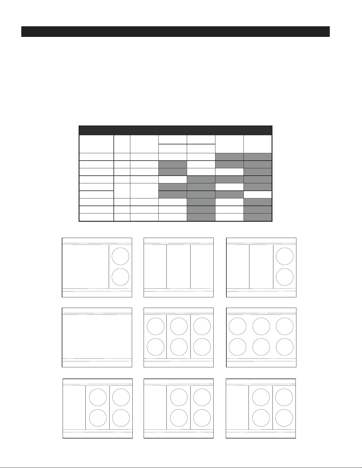
The range surface can come in 5 different congurations (shown below).
Controls
The RT36 Series Range is available with various controls depending upon model number. Shown below are layouts
of each top conguration with its proper model number and a brief description of the controls.
The RT36 provides three (3) options for the bottom of the range. A standard bake oven, convection oven, or just as a
range top.
RangeSurfaceCongurations
Model Conf. Controls
Griddle Hot Tops
450°F 850°F
RT36-ATA A 4 24” 12”
RT36-ATB B 3 36”
RT36-ATC C 4 24” 2
RT36-ATD D 3 36”
RT36-ATE
RTI36-ATE 6
E 6
RT36-ATF F 5 12” 4
RT36-ATG G 5 12” 4
RT36-ATJ F 5 12” 4
French
Plates
6
Wave
Induction
4
2M-W1091, Commerical & Marine Electric Range Top
Page 5
2M-W1091, Commerical & Marine Electric Range Top52M-W1091, Commerical & Marine Electric Range Top
UNPACKING
Receiving the Range
Upon receipt, check for freight damage, both visible and concealed. Note visible
damage on the freight bill at the time of delivery and require the carrier’s agent to
sign the freight bill. Concealed loss or damage means loss or damage, which does
not become apparent until the merchandise has been unpacked. If concealed loss
or damage is discovered upon unpacking, make a written request for inspection
by the carrier’s agent within 15 days of delivery. Keep all packing material for
inspection. Do not return damaged merchandise to Lang Manufacturing, le your
claim with the carrier.
Location
Prior to un-crating, move the range as near its intended location as practical. The crating will help protect
the unit from the physical damage normally associated with moving it through hallways and doorways.
Un-crating
The range will arrive completely assembled inside a wood frame covered by cardboard box and strapped
to a skid. Remove the cardboard cover, cut the straps and remove the wood frame.
RANGE WEIGHS 410 LBS (186 kilograms). FOR SAFE HANDLING, INSTALLER
SHOULD OBTAIN HELP AS NEEDED, OR EMPLOY APPROPRIATE MATERIALS
HANDLING EQUIPMENT (SUCH AS A FORKLIFT, DOLLY, OR PALLET JACK)
TO REMOVE THE UNIT FROM THE SKID AND MOVE IT TO THE PLACE OF
INSTALLATION.
CAUTION
ANY STAND, COUNTER OR OTHER DEVICE ON WHICH RANGE WILL BE
LOCATED MUST BE DESIGNED TO SUPPORT THE WEIGHT OF THE OVEN
(410 LBS.).
SHIPPING STRAPS ARE UNDER TENSION AND CAN SNAP BACK WHEN
CUT.
Remove range from skid and place in intended location.
INSTALLING THE LEGS
Legs or Casters are available and must be specied upon ordering.
To install the 6-inch legs, remove the legs from the range packing, place some cardboard on the oor and
gently tip the range onto its back. Fasten the legs into the threaded holes provided and then gently ip
the oven onto its legs.
To install the 6-inch casters, remove the casters from the oven cavity, place some cardboard on the oor
and gently tip the range onto its back. Attach the casters to the adapter plates. Install the four adapter
plates (one in each corner with the ange pointed toward the oven). Gently tip the oven onto its casters.
Page 6
2M-W1091, Commerical & Marine Electric Range Top
IL2314
CAUTION
INSTALLATION
Electrical Connection
Make all electrical connections in accordance with local codes or
in the absence of local codes with NFPA No. 70 latest edition (in
Canada use: CSA STD. C22.1).
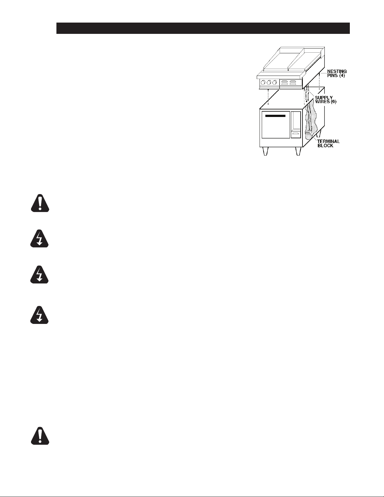
Place spacers, (i.e. 2x4 wood block not supplied) at the front and
rear of the oven top.
Place the range top on the spacers that are located on top of the
oven.
The six wire leads that supply electricity to the cook top are bundled
under the front of the top. Route the six wires through the bushing
provided in the oven top.
Align the four locating pins in the bottom corner of the top with the
four holes in each corner of the oven top.
Remove the spacers and lower the top onto the oven.
The range can now be connected to power.
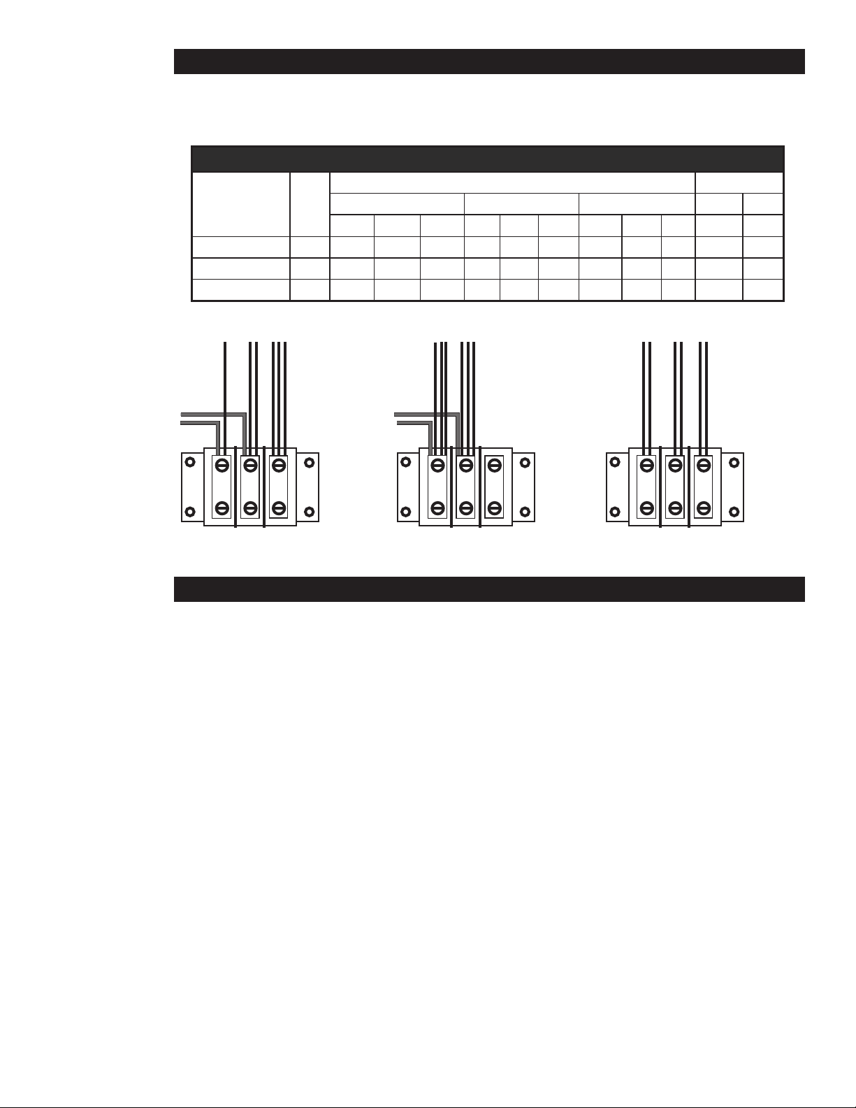
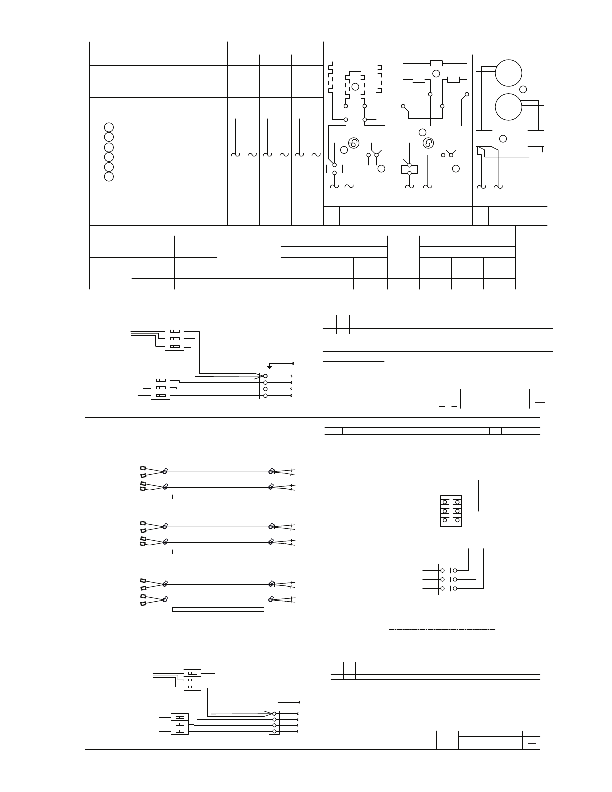
Use the wiring diagram provided in this manual for determining the connections of the cook top wires to
the oven terminal block.
MAKE SURE THE SIX WIRE LEADS TO SUPPLY ELECTRICITY TO THE RANGE
TOP ARE NOT CRIMPED BETWEEN THE OVEN AND RANGE TOP. FAILURE
TO COMPLY WILL RESULT IN DAMAGE TO EQUIPMENT.
WARNING
WARNING
WARNING
NOTICE
NOTICE
TURN OFF THE MAIN POWER SUPPLY TO THE RANGE AT THE SOURCE
PRIOR TO CONNECTING POWER TO THE RANGE. FAILURE TO COMPLY MAY
RESULT IN SERIOUS INJURY AND OR DEATH.
THIS APPLIANCE MUST BE GROUNDED AT THE TERMINAL PROVIDED.
FAILURE TO GROUND THE APPLIANCE COULD RESULT IN ELECTROCUTION
AND DEATH.
INSTALLATION OF THE UNIT MUST BE DONE BY PERSONNEL QUALIFIED TO
WORK WITH ELECTRICITY AND PLUMBING. IMPROPER INSTALLATION CAN
CAUSE INJURY TO PERSONNEL AND/OR DAMAGE TO EQUIPMENT. UNIT
MUST BE INSTALLED IN ACCORDANCE WITH ALL APPLICABLE CODES.
The data plate is located right of range top controls. The oven voltage, wattage,
serialnumber,wiresize,andclearancespecicationsareonthedataplate.
This information should be carefully read and understood before proceeding
with the installation.
2M-W1091, Commerical & Marine Electric Range Top
The installation of any components such as a vent hood, grease extractors,
reextinguishersystems,must conformtotheir applicableNational,State
and locally recognized installation standards.
CAUTION
BE SURE THE POWER SUPPLY VOLTAGE MATCHES THE VOLTAGE SPECIFIED
ON THE NAMEPLATE LOCATED ON THE FRONT OF THE RANGE. FAILURE
TO COMPLY MAY RESULT IN PERSONAL INJURY AND/OR DAMAGE TO
EQUIPMENT
6
Page 7
2M-W1091, Commerical & Marine Electric Range Top72M-W1091, Commerical & Marine Electric Range Top
INSTALLATION continued
3 1,5 2,4,6
TO RANGE
TOP
TO
OVEN
Three Phase with Oven
L1 L2 L3
4,51,3 6,2
TERMINAL BLOCK
RANGE TOP ONLY
Three Phase w/o Oven
L1 L2 L3
2,4,61,3,5
TO RANGE
TOP
TO
OVEN
Single Phase with Oven
L1 L2 L3
IL1412a
Electrical Connection
The following table and illustrations provide the voltage and kilowatts necessary to operate the range
and oven
ElectricalSpecications
Three Phase Single Phase
Total
Range style
k.W.
Range Top Only 15
W / Conv. Oven 21.6 48.3 69.2 62.5 41.9 59.9 54.1 20.5 29.5 27.1 103.8 90
W / Bake Oven 21 45.8 66.7 62.5 39.7 57.8 54.1 19.9 28.9 27.1 101 87.5
208 Volt 240 Volt 480 Volt 208 V 240 V
L1 L2 L3 L1 L2 L3 L1 L2 L3 L1 L2
41.7 41.7 41.7 36.1 36.1 36.1 18.1 18.1 18.1 72.1 62.5
INITIAL START-UP
Hot Plates
To “dry out” the hot plate, set the thermostat dial at 250°F and turn on the power switch. Allow unit
to cycle at least 15 minutes at this heat level. Reset the thermostat to 350°F allowing the same time.
Then reset the thermostat to 450°F allowing the same time. Continue doing this until you reach
850°F then allow the unit to maintain this temperature for a minimum of 4 hours. More time may be
required if the unit has to operate in a moist environment.
If the unit is out of use for three or more days, a one-hour preheat schedule should be used,
especially when exposed to high humidity and/or cool temperatures.
French Plates
To “dry out” the Frenchplate, set the six-heat switch to the rst setting and turn on the power switch.
Allow unit to cycle at least 15 minutes at this heat level. Reset the six-heat switch to position 2 and
allow the same time. Reset the six-heat switch to position 3 and allow the same time. Continue
doing this until you reach position 6 then allow the unit to maintain the temperature for a minimum of
4 hours. More time may be required if the unit has to operate in a moist environment.
If the unit is out of use for three or more days, a one-hour preheat schedule should be used,
especially when exposed to high humidity and/or cool temperatures.
Page 8

2M-W1091, Commerical & Marine Electric Range Top
NOTICE
INITIAL START-UP continued
Induction Hot Plates
Induction requires cookware that is induction efcient or that is made for use on an induction surface.
Generally speaking if a magnet attracts and strongly adherse to the pan bottom it will generally work on
an induction surface. This is a requirment for proper use. DO NOT USE WITH EMPTY PANS.
To operate unit turn the knob clockwise and a small digital number will appear next to the hotplate to
be cooked on. The higher the number the faster the heat up. Heating will begin when the pan surface
comes in contact with the induction surface and will cease when the pan is removed. Note: surface will
remain hot for a certain period of time after the pan is removed.
Induction module, controlled by variable heat control. Great for rapid heat-up, it will generally boil water,
heat sauces or soups in about half the time of a French Plate. Use caution placing items on the glass
cook surface, always wipe down glass with mild soap and water to keep the unit clean.
Griddles
To “dry out” the griddle, set the thermostat to 250°F and turn on the power switch. Allow the unit to cycle
at least 15 minutes at this heat level. Reset the thermostat to 350°F allow the same time. Reset the
thermostat to 450°F and allow the unit to maintain the temperature for a minimum of 4 hours. More time
may be required if the unit has to operate in a moist environment.
If the unit is out of use for three or more days, a one-hour preheat schedule should be used, especially
when exposed to high humidity and/or cool temperatures.
Duringthe rst few hours of operation you may notice a small amount of
smoke coming off the range, and a faint odor from the smoke. This is normal
foranewrangeandwilldisappearaftertherstfewhoursofuse.
CAUTION
ALWAYS KEEP THE AREA NEAR THE APPLIANCE FREE FROM COMBUSTIBLE
MATERIALS.
KEEP FLOOR IN FRONT OF EQUIPMENT CLEAN AND DRY. IF SPILLS OCCUR,
CLEAN IMMEDIATELY, TO AVOID THE DANGER OF SLIPS OR FALLS.
RANGE TOP
Consists of the various top arrangements, depending on specic model purchased:
12” x 24” hot plate controlled by high temperature thermostats. Temperature ranges from 0°F-850°F.
Recommended: Stock pots and heavy kettle work.
Round French Plates, controlled by indicating type 6-heat switch. Temperature ranges from 0°F-750°F.
Recommended: Light duty sauce pans and small stockpots. Not Recommended: Heavy stock pots, or
heavy urns, or kettles.
36” x 24” or 24” x 24” grill plates, controlled by thermostats. Temperature ranges from 0°F-450°F.
Recommended: All heavy and light frying. Set the thermostat dial at the desired temperature. The red
pilot light will be on until the desired temperature is reached. The pilot light indicates that the plate is
heating.
2M-W1091, Commerical & Marine Electric Range Top
8
Page 9

2M-W1091, Commerical & Marine Electric Range Top92M-W1091, Commerical & Marine Electric Range Top
CAUTION
MAINTENANCE AND CLEANING
Cleaning
The range should be thoroughly cleaned at least once a week in addition to the normal daily cleaning to
insure against the accumulation of foreign material.
Any oven cleaner used should be marked “Safe On Aluminum”.
Electric equipment is inherently clean and sanitary, but may become unsanitary if dirt is allowed to
accumulate on it. Take advantage of the clean, sanitary features of electric equipment, give it the regular
attention that it deserves the same as any other highly perfected machinery, to insure best results and
continued high operating efciency.
Always start with a cold griddle, french plate, hot plate or induction surface.
•
The stainless exterior can easily be cleaned using a good non-abrasive cleaner.
•
Always follow the cleaner manufacturer’s instructions when using any cleaner.
•
Always apply these cleaners when the griddle is cold and rub in the direction of the metal’s
•
grain.
Keep-drip pans under the range top plates clean.
•
Keep the hotplate and griddle surfaces clean.
•
Outside of the range and top should be kept clean.
•
Induction Hot Plate Surface Care
Use only cook-top cleaning creme on glass-ceramic cooking surfaces. Wipe the ceramic cooking
surfaces with cleaning creme and a clean cloth. The cleaning creme leaves a protective coating.
CAUTION
DO NOT USE ABRASIVE CLEANERS ON THE INDUCTION GLASS COOKTOP
SURFACE, AS THIS COULD SCRATCH AND DAMAGE THE GLASS SURFACE.
USE ONLY WATER WITH A MILD DISHWASHING SOAP.
Griddle Surface Care (non-chromium surfaces)
It takes very little time and effort to keep the griddle attractive and performing at top efciency. If grease
is permitted to accumulate, it will form a gummy cake and then carbonize into a hard substance which is
extremely difcult to remove. To prevent this condition, the following suggestions for cleanliness should
be followed:
•
After each use, scrape the griddle with a scraper or exible spatula to remove excess grease
and food. A waste drawer is provided for the scrapings. If there is an accumulation of burned
on grease and food, the griddle should be thoroughly scoured and re-seasoned. Use pumice or
griddle stone while the griddle is warm.
Do not use steel wool because of the danger of steel slivers getting into the food. MAINTENANCE AND
CLEANING
Page 10
2M-W1091, Commerical & Marine Electric Range Top
MAINTENANCE AND CLEANING continued
Calibration
Calibration Check
•
Place thermometer in the center of oven cavity.
•
Set thermostat to 350°F and place both 3-heat switches in the “HIGH” position.
•
Allow the oven to Preheat for at least half an hour.
NOTE
Cycle on temperatures and cycle off temperatures for 3 cycles.
(Red indicator light indicates when oven is calling for heat)
After 3 cycles average the temperature. ( Add all six temperatures and divide by 6)
Calibration Adjustment
•
A 1/16” at blade screwdriver with a 2” shaft is required to make adjustments to the
thermostat.
•
Maintain the oven temperature at 350°F.
•
Without turning the thermostat, remove the knob.
•
Locate the adjustment screw at the base of the shaft and insert the screwdriver.
•
Hold the shaft and turn the screwdriver counter clockwise to increase the temperature and
clockwise to decrease the temperature. (1/8 of a turn will move the temperature 5-7 °F in
either direction).
•
Reinstall the oven knob and recheck the oven temperature.
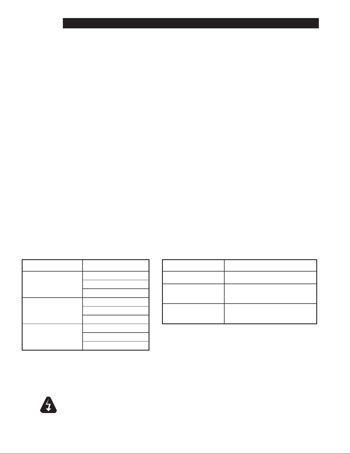
Troubleshooting
Troubleshooting is not an exact science. Several factors may play a part in why your machine is
not operating correctly. The following symptoms are a general idea of what may be causing the
malfunction and should not be considered the complete answer to the situation that you have with
your machine. Here are some of the possible problems you may encounter and possible solutions to
those problems
Symptom Possible Cause
No power to Unit
Hotplate will not heat
French plate will not heat
Griddle plate will not heat
Defective Thermostat
Defective element
No power to Unit
Failed 6-heat switch
Failed element
No power to Unit
Failed Thermostat
Failed element
Service on this or any other Lang appliance must be performed by
NOTICE
qualied personnel only. Consult your Lang Authorized Service
Agent Directory. You can call us at 314-678-6315 or visit our website
www.langworld.com for the service agent nearest you.
WARNING: BOTH HIGH AND LOW VOLTAGES ARE PRESENT INSIDE
THIS APPLIANCE WHEN THE UNIT IS PLUGGED/WIRED INTO A LIVE
WARNING
RECEPTACLE. BEFORE REPLACING ANY PARTS, DISCONNECT THE
UNIT FROM THE ELECTRIC POWER SUPPLY.
Possible Cause Test
Failed thermostat Verify calibration
Failed element
Failed 6-heat switch
If an item on the list is followed by an asterisk (*), the work
should be done by a factory authorized service representative
Remove the wires and check for continuity
across the element*
Call factory or consult service manual for
proper tests
2M-W1091, Commerical & Marine Electric Range Top
10
Page 11
2M-W1091, Commerical & Marine Electric Range Top112M-W1091, Commerical & Marine Electric Range Top
MAINTENANCE AND CLEANING continued
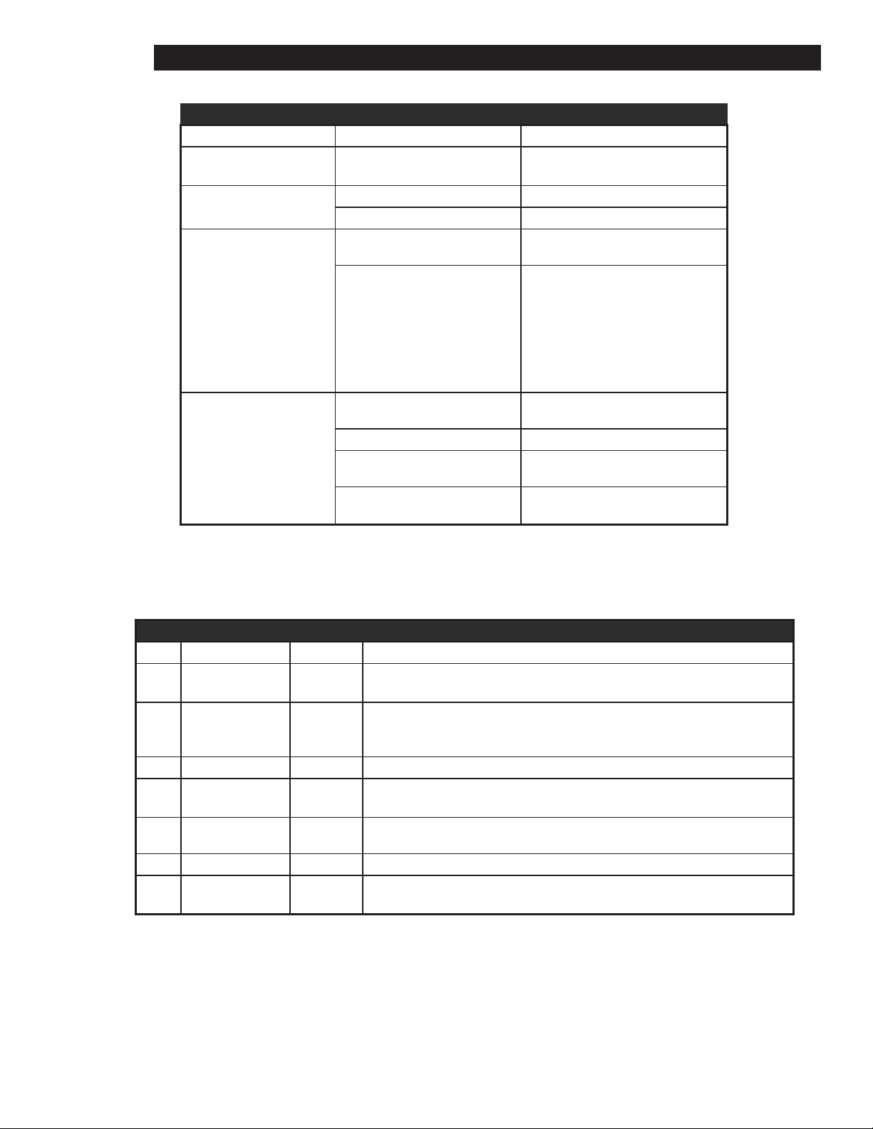
Induction Troubleshooting
INDUCTION TROUBLESHOOTING
Symptom Probable Cause Possible Solution
No Power
(no lights or fan noise)
Pan does not heat
Unit suddenly stops
heating
Power the unit, disconnecteed or
circuit breaker open.
Pan is not induction efcient Use induction efcient pan
Pan not centered center pan
Possible power brown out Verify proper voltage/power
Safety shut-off engaged
Pan not unduction efcient Use induction efcient pan
Turn on main power switch, check
circuit breaker.
The safety shut off will engage if
an empty pan is left on the cooktop
surface while the unit is working at
full power. Make sure the cooktop
surface is clear. Wait 15-20 minutes
for the unit to reset.
Pan heats unevenly or
over heats
In the event of a possible malfunction your Lang Wave module will display an error code on the display.
See below when encountering an error code on your display. To reset error conditions remove the pan
from the unit and turn off power to the unit.
Error Cause Code Troubleshooting
Broken Temp
1
Sensor
Glass Temp. to
2
high
3 Over Current E-03 Try different cookware, current may be required
Over heat or air
4
ow restriction
6 Hig Line Voltage E-06 To reset, turn OFF unit power & turn on again. Verify power line voltage.
Pan bottom may not be at Use at pan
Pan not centered Center pan
Pan is less than 7” dia Use larger induction efcient pan.
INDUCTION ERROR CODES
E-01 Service required to replace sensor
E-02
Air-Flow Make sure air inlet vents in the rear are not restricted, listen for unit fan operation
Remove pans from surface & let unit cool. Turn unit power OFF & then ON. If
unit does not return to normal operation, service is required.
7 Hardware Failure E-07 Service required
Zero Cross
8
Failure
E-08 Turn OFF unit, then turn ON. If problem persists, service is required.
Page 12
2M-W1091, Commerical & Marine Electric Range Top
3
J3
J3
J3
J3
Rotary
Switch
Rotary
Switch
Rotary
Switch
Rotary
Switch
Rotary
Switch
Rotary
Switch
J3
J3
4 C.B. C.B. C.B.
W
W
W
W
W
W
5 6 1 2
INDUCTION COOKTOP 30”
RANGE TOP
INDUCTION COOKTOP 36”
RANGE TOP
SK2526
RTI30 & RTI36 INDUCTION COOKTOP
GRIDDLE
HOT TOP
FRENCH PLATE
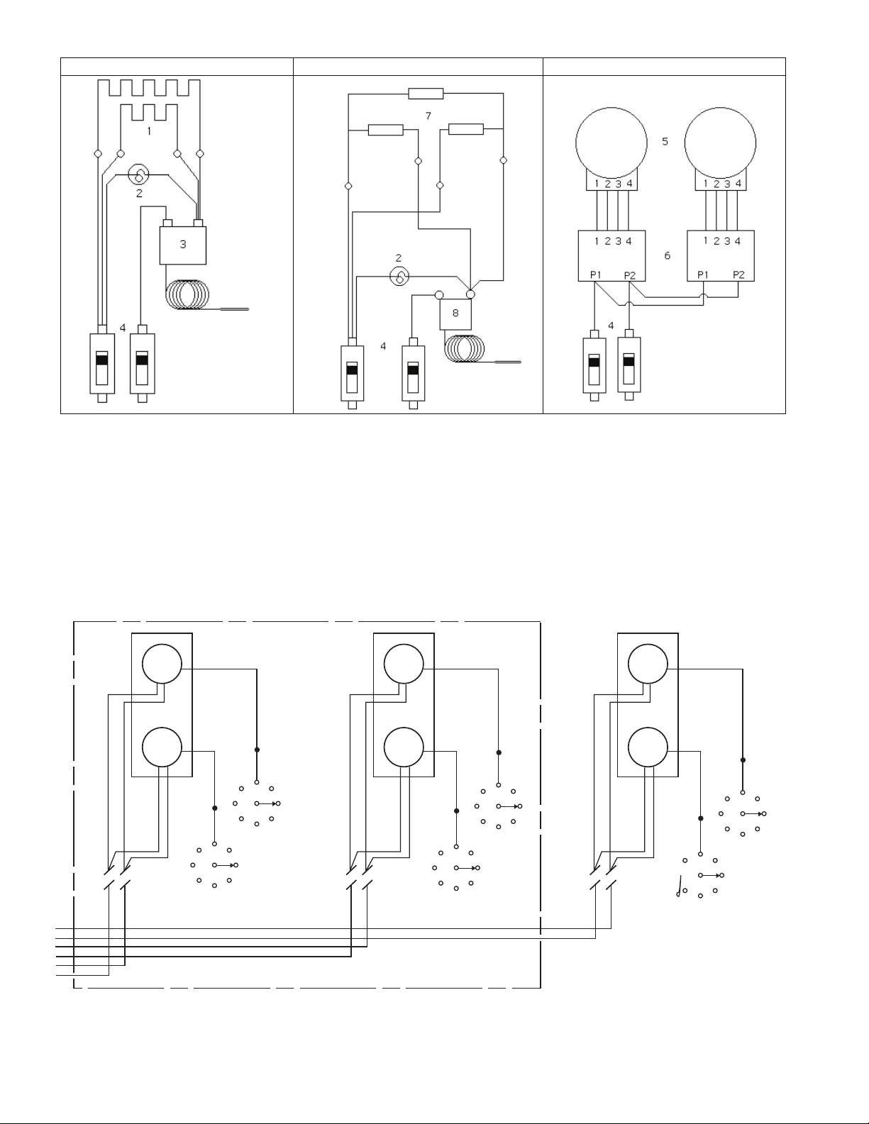
1. Griddle and Top Plate Element
2. Pilot Light
3. 450°F Griddle Theremostat
4. Circuit Breaker
5. French Plate
6. 6-Heat Switch
7. Hot Top
8. 850°F Hot Top Thermostat
12
2M-W1091, Commerical & Marine Electric Range Top
Page 13
2M-W1091, Commerical & Marine Electric Range Top132M-W1091, Commerical & Marine Electric Range Top
NONE
1
2
3
4
5
6
1
6
3
1667
1667
1667
4
1
3
2
2
1
2
3
4
3
4
2 1 3 4 2 1 3 4
3
1
5
4
2
1
L
N
L
N
L
N
L
L
L
SEE PAGE 2 FOR MORE DETAIL
THERMOSTAT
SIX HEAT SWITCH
PILOT LAMP
SPEED UNIT-(EGO)
HEAT ELEMENT
CAST HOT TOP
MODEL DESIGNATION
TOP ARRANGEMENT
SEC-1
A
C
A
B
B
SEC-2
A
C
A
B
B
SEC-3
A
C
C
B
C
TOP SECTION WIRE DIAGRAMS
A B C
GRILL HOT TOP
SPEED UNITS
36S-11
36S-21
36S-5
36S-7
36S-8A
POWER
SUPPLY
PHASE
SINGLE
BREAKER
CIRCUIT
TOP
COOK
ELECTRICAL CONNECTIONS
L1
L2
L3 3
2
1
ELECTRICAL DATA
MODEL
LOADING
KW PER PHASE
TOTAL
KW
36S COOK TOP
5.0 5.0 5.0 15.0
L1 L2 L2 L3 L3 L1
AMPS
220 V. (L-N)
22
L1
22
L2 L3
2000
3000
1 N 2 N 3 N
TO BREAKER
TO BREAKER
TO BREAKER
22
USED ON A 5 WIRE SUPPLY SYSTEM WITH 380V.
(INDUCTION)
3 PH. SUPPLY WITH A NEUTRAL AND GROUND WIRE.
NEXT HIGHER ASSY.
TITLE:
LANG MANUFACTURING
SCALE:
QTY
CK:
DR: SRC
DIMENSIONS ARE IN INCHES
UNLESS OTHERWISE SPECIFIED
DATE:
TOLERANCES
.XXX ± .015
DECIMALS
.XX ± .03
FRACTIONS
± 1/64
± .5°
ANGLES
DATE:
.X ± .05
PART NUMBERITEM
OF
DESCRIPTION / MATERIAL
SHEET
CREATED BY STUART R. CARTIER
DRAWING NUMBER REV
- -
N
L1
L2
L3
SUPPLY
GROUND
L1
L2
L3
N
MODULE SET 1 (LEFT)
MODULE SET 2 (MIDDLE)
MODULE SET 3 RIGHT
CIRCUIT BREAKER LEFT
CIRCUIT BREAKER RIGHT
RANGETOP CIRCUIT (INDUCTION MODULES)
BASE CIRCUIT
FROM MODULES
N
N
TERMINAL BLOCK
380 V.
3 PH.
W/NEUTRAL
36S COOK TOP
220/380 VAC
61106-14
1 2
5-2-13
9"
7"
9"
7"
46"
1
2
1
2
9"
7"
7"
46"
9"
1" I.D. GLASS SLEEVING (2H-71400-09)
24"
3
4
7"
24"
3
4
46"
9"
1" I.D. GLASS SLEEVING (2H-71400-09)
7"
9"
9"
7"
9"
46"
7"
5
6
7"
24"
5
6
46"
9"
1" I.D. GLASS SLEEVING (2H-71400-09)
7"
9"
9"
7"
9"
46"
7"
INDUCTION
MODULE 1
1 & 1 TO
C.B. #1 L1
2 & 2 TO
C.B. #4 NEUTRAL
FRONT
BACK
FRONT
BACK
INDUCTION
MODULE 2
FRONT
BACK
INDUCTION
MODULE 3
NOTE: CIRCUIT BREAKERS
ARE FOR REFERENCE ONLY.
NOT PART OF THE HARNESS
SUPPLY
CIRCUIT BREAKER
#2 ON RIGHT
SUPPLY
CIRCUIT BREAKER
#1 ON LEFT
#1
#2
#3
#5
#6
#4
OUT TO
INDUCTION
TOPS
OUT TO
INDUCTION
TOPS
3 & 3 TO
C.B. #2 L2
4 & 4 TO
C.B. #5 NEUTRAL
5 & 5 TO
C.B. #3 L3
6 & 6 TO
C.B. #6 NEUTRAL
#6
#4
#3
#1
#5
#2
L1 L2 L3
NN N
NONE
N
L1
L2
L3
SUPPLY
GROUND
L1
L2
L3
N
MODULE SET 1 (LEFT)
MODULE SET 2 (MIDDLE)
MODULE SET 3 RIGHT
CIRCUIT BREAKER LEFT
CIRCUIT BREAKER RIGHT
RANGETOP CIRCUIT (INDUCTION MODULES)
BASE CIRCUIT
FROM MODULES
N
N
TERMINAL BLOCK
380 V.
3 PH.
W/NEUTRAL
USED ON A 5 WIRE SUPPLY SYSTEM WITH 380V.
3 PH. SUPPLY WITH A NEUTRAL AND GROUND WIRE.
NEXT HIGHER ASSY.
TITLE:
LANG MANUFACTURING
SCALE:
QTY
CK:
DR: SRC
DIMENSIONS ARE IN INCHES
UNLESS OTHERWISE SPECIFIED
DATE:
TOLERANCES
.XXX ± .015
DECIMALS
.XX ± .03
FRACTIONS
± 1/64
± .5°
ANGLES
DATE:
.X ± .05
PART NUMBERITEM
OF
DESCRIPTION / MATERIAL
SHEET
CREATED BY STUART R. CARTIER
DRAWING NUMBER REV
REV ECN NO. DATE
REVISION BLOCK
DESCRIPTION MFGDR: ENG
- -
36S COOK TOP
220/380 VAC
61106-14
2 2
5-2-13
Page 14
2M-W1091, Commerical & Marine Electric Range Top
SK2265 Rev. B 8/2/11
Model:
36" Range Top
Old Style Sea Rails
22
21
20
18
19
23
24
25
26
3
4
5
6
7
8
9
10
11
13
14
15
12
16
17
1
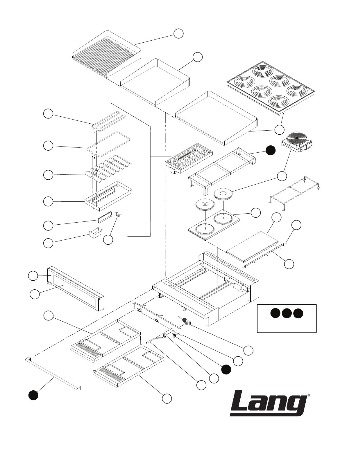
Marine Application
12
4
16
Note: if grooving is
required, contact factory
1
CERTAIN INSTANCES MAY NOT BE AVAILABLE
ILLUSTRATIVE PURPOSES ONLY AND IN
SOME ITEMS ARE INCLUDED FOR
2M-W1091, Commerical & Marine Electric Range Top
14
Page 15
2M-W1091, Commerical & Marine Electric Range Top152M-W1091, Commerical & Marine Electric Range Top
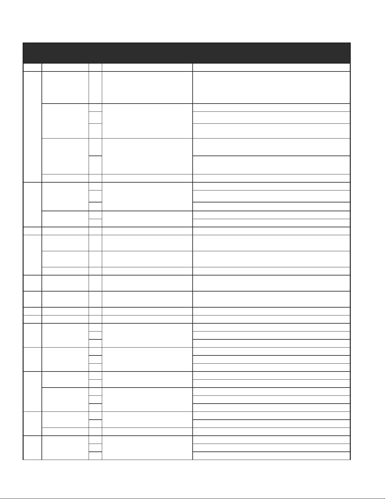
PARTS LIST July 24, 2012
Model No: RT36A, RT36B, RT36C, RT36D, RT36E, RT36F, RT36G
COMMERCIAL & MARINE ELECTRIC RANGE TOP
Fig No Part No Qty Description Application
P9-50401-09
1
P9-50401-02 RANGE PLATE ASSY 1/2” X 2’ ALL RT36A VM
P9-50401-03
P9-50401-11 RANGE PLATE ASSY 1/2” X 3’ ALL RT36D V
3
P9-50403-10 RANGE PLATE ASSY 1” X 3’ RT36D1
P9-RF21-740 1 TOP GLASS ASSY-36” INDUCTION
PS-71300-22 AR GLASS ONLY - 36” INDUCTION
P9-50302-301
4
P9-50302-303-1 SEARAIL ASSY 1’ {ADD} SK ALL RT36A AND RT36C VM
2N-11120-12
2N-11120-13
5
2N-11120-14
2N-11120-18 ELMNT TK 380V 2000W RT36E-380V
2N-11120-26 6 INDUCTION MOD-2600W 208/240 RTI36E
P9-50300-82-1
6
P9-50300-83 2 EGO FRENCH HOT PLATE RT36F-480VM
PS-11010-341
7
PS-11010-351
PS-11010-361
8 2C-21003-02 10 SCRW SECRTY 1/4-20 2-EAR RT36B-480VCP
9 P9-RF21-820 2 HOT TOP HLDER ASY CORR. PKG RT36B-480VCP
2E-30304-09
2T-30402-08
10
2T-30402-23
2E-30304-14 6 CONTROL MODULE-INDUCTION RTI36E
P9-RF21-304
11
P9-RF21-305 CONTROL PANEL C&G ALL RT36C AND RT36G
P9-RF21-306 CONTROL PANEL A&D ALL RT36A AND RT36D
12 Y9-50300-63 1 MARINE PAN LATCH ASSY
RANGE PLATE ASSY 1” X 2’ ALL RT36A V
1
RANGE PLATE ASSY 1/2” X 3’ ALL RT36D VM
1
RTI36
SEARAIL ASSY 3’ {RF&500} ALL RT36E-VM, RT36F-VM
1
2
ELMNT TK 208V 2600W
4 RT36F-208V & VM, RT36J-208V
RT36A-208V & VM, RT36C-208V, RT36A1-208V
6 RT36E-208V & VM
2
ELMNT TK 240V 2600W
4 RT36F-240V & VM
RT36A-240V & VM, RT36C-240V & VM
6 RT36E-240V & VM
2
ELMNT TK 480V 2600W
4 RT36F-480VM
6
1
EGO PLATE FRM ASY PHANT
3 ALL RT36E
1
HOTPLATE 208V 5000W CAST
2 RT36C-208V
RT36A-440VM, 480V & VM, RT36C-440VM, 480V & VM
RT36E-440VM, 480V & VM
RT36A-208V & VM, 240V, ALL RT36C
RT36F-208V & VM, RT36J-208V
3 RT36B-208V & VM
1
HOTPLATE 240V 5000W CAST
3 RT36B-240V, RT36C-240V & VM, RT36F-240VM
1
HOTPLATE 480V 5000W CAST
3 RT36B-440VM, 480V & VM, RT36C-440VM, 480V & VM
2
SWTROT 6 HEAT+OFF208/240V
4 ALL RT36G
RT36F-240V & VM
RT36F-440VM & 480VM
RT36A-208V & VM, 240V, 440VM, 480V & VM, RT36B-440VM,
ALL RT36C
6 ALL RT36E
1
2 ALL RT36A
STAT ADJ 450o 72 C/T
ALL RT36G
3 ALL RT36D
3
STAT ADJ 850° 48C/T NAK
2 ALL RT36C
ALL RT36B
1 ALL RT36F, RT36J
CONTROL PANEL H ALL RT36E
1
ALL RT36A VM, ALL RT36B VM & VCP, ALL RT36C VM, RT36D208VM & 240VM & 440VM, ALL RT36E VM
Page 16
2M-W1091, Commerical & Marine Electric Range Top
PARTS LIST October 4, 2012
Model No: RT36A, RT36B, RT36C, RT36D, RT36E, RT36F, RT36G
COMMERCIAL & MARINE ELECTRIC RANGE TOP
Fig No Part No Qty Description Application
P9-70701-35
(Black),
P9-70701-35-2
(Red)
P9-70701-41
(Black),
P9-70701-41-2
13
(Red)
1 KNOB ASSY 850° B ALL RT36F, RT36J
3
4 ALL RT36A AND RT36C, RT36F
KNOB ASSY 6 HEAT EGOTK
ALL RT36B AND RT36D
6 ALL RT36E
Y9-70701-16
(Black),
Y9-70701-16-2
(Red)
2
ALL RT36A; RT36C-440 VM,480 V AND VM
KNOB ASSY 450o A
3 ALL RT36D; ALL RT36B; RT36C-208 V AND VM, 240 V AND VM
PS-70700-09-1 6 KNOB ASSY-INDUCTION RTI36E
14
2J-31601-01
2J-31601-02
1
2 RT36A-208V & VM, 240V & VM, RT36C-208V & VM, 240V & VM
PILOT LT 250V 6LEAD BLK
3 RT36B-208V & VM, 240V & VM, RT36D-208V & VM, 240V & VM
2
PILOT LT 480V 6LEAD BLK
3 RT36B-440VM, 480V & VM, RT30D-440VM & 480V
RT36F-208V & VM, RT36F-240V & VM, RT36F-208V
RT36A-440VM, 480V & VM, RT36C-440VM, 480V & VM
14 Y9-31601-02-1 3 PILOT LT 480V W/TIN CLIP PHANT RT36D 480 SUB
P9-RF21-415-1 2 PAN ASSY (304 S/S)
15
PS-60102-W1232 1 RF21 MARINE PAN ASY-RIGHT
ALL RT36A V, ALL RT36B V, ALL RT36C V, RT36D-208V & 240V,
ALL RT36E V
ALL RT36A VM, ALL RT36B VM, ALL RT36C VM, RT36D-208VM
& 240VM & 440VM, ALL RT36E VM
P9-RF21-750 2 PAN WLDMENT ASSY-INDUCTION RTI36E
16 P9-50300-44-1 1 GRAB BAR ASSY 36 RANGE
17 M9-60102-290 1 MARINE PAN ASSY - A/L
ALL RT36A VM, ALL RT36B VM, ALL RT36C VM, ALL RT36D
VM, ALL RT36E VM
ALL RT36A VM, ALL RT36B VM, ALL RT36C VM, ALL RT36D
VM,ALL RT36E
18 P9-RF21-803 1 WINDOW - CP RF21 RT36B-480VCP
19 P9-RF21-800 1 DOOR ASSY - CP RT36B-480VCP
20 P9-50306-25
2
WIRE BRACKET ASSY TILT-UP
3 ALL RT36D
ALL RT36A
1 ALL RT36G
21 P9-50306-33
3
ELEM TERMINAL GUARD
2 ALL RT36A
ALL RT36D
1 ALL RT36G
22
P9-50300-22
P9-50300-43
2
208-240 V 3/16 BULB HOLDER
3 ALL RT36D 208, 240 V AND VM
2
480 V 3/16 BULB HOLDER
3 ALL RT36D 440VM, 480 V AND VM
ALL RT36A 208, 240 V AND VM
ALL RT36A 440VM, 480 V AND VM
1 ALL RT36D 440VM
23
P9-50300-41
2
ELEM PAN ASSY (W/SNOUT) 5KW
3 RT36D 208, 240 V AND VM
RT36A 208, 240 V AND VM
P9-50300-43 1 480 V 3/16 BULB HOLDER ALL RT36G
24 P9-50300-42
2
ZIG ZAG ASSY (W/SNOUT) 5KW
3 ALL RT36D
ALL RT36A
1 ALL RT36G
2M-W1091, Commerical & Marine Electric Range Top
16
Page 17

2M-W1091, Commerical & Marine Electric Range Top172M-W1091, Commerical & Marine Electric Range Top
PARTS LIST October 4, 2012
Model No: RT36A, RT36B, RT36C, RT36D, RT36E, RT36F, RT36G
COMMERCIAL & MARINE ELECTRIC RANGE TOP
Fig No Part No Qty Description Application
2N-11010-09
2N-11010-21
25
2N-11010-23
2
ELMNT T/P 208V 2KW O/S
3 RT36D 208 V AND VM
2
ELMNT T/P 240V O/S 2KW
3 RT36D 240 V AND VM
2
ELMNT T/P 480V O/S 2KW
3 RT36D 480 V AND VM, 440 VM ;480 SUB
1 RT36G
2N-11010-25
2N-11010-10
2N-11010-22
26
2N-11010-24
3
ELMNT T/P 380V O/S 2KW
1 RT36G-380VM
2
ELMNT T/P 208V 3KW I/S
3 RT36D 208 V AND VM
2
ELMNT T/P 240V I/S 3KW
3 RT36D 240 V AND VM
2
ELMNT T/P 480V I/S 3KW
3 RT36D 480 V AND VM, 440 VM, 480 SUB
1 RT36G
2N-11010-26
3
ELMNT T/P 380V I/S 3KW
1 RT36G-380VM
NI 2E-30500-08 1 TRM BLOCK 2 POLE SMALL 95 RT36A-440VM, 480V & VM, RT36C-440VM, 480V & VM
NI 2E-30500-09 1 TRM BLOCK 3 POLE SMALL 95 RT36B-440VM, 480V & VM, RT36D-440VM, 480V & VM
NI 2E-31800-01 6 CB 250V50A 1 POLE CRLNGSW
RT36A 208 V AND VM, RT36A1-208V
RT36A 240 V AND VM
RT36A 480 V AND VM, 440 VM
RT36D-380VM
RT36A 208 V AND VM, RT36A1-208V
RT36A 240 V AND VM
RT36A 480 V AND VM, 440 VM
RT36D-380VM
RT36A-208V & VM, 240V & VM, RT36B-208V & VM, 240V & VM,
RT36C-208V & VM, 240V & VM, RT36D-208V & VM, 240V & VM,
RT36E-208V & VM, 240V & VM, RT36F, RT36J
Page 18
2M-W1091, Commerical & Marine Electric Range Top
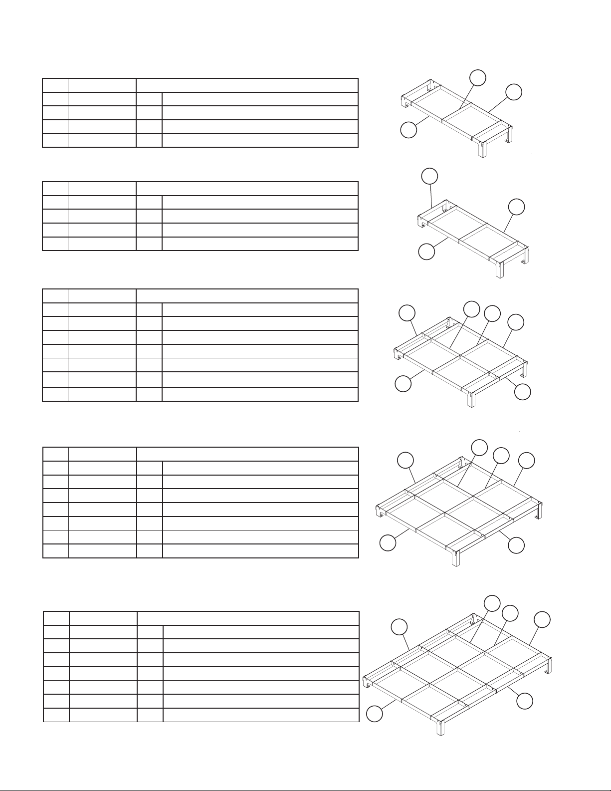
Lang Manufacturing Searail Assembly
Part No. Qty Description
50302-297-1 SEARAIL ASSY 1’ {RF&500} SK
A 50302-305 1 SEARAIL LH SIDE {ADD,RF & 500}
B 50302-306 1 SEARAIL RH SIDE {ADD,RF & 500}
C 50302-317 5 SEARAIL SIDE TO SIDE 12”
20109-04 8 SCREW THD MS SS 10-32X 3/8
Part No. Qty Description
50302-303-1 SEARAIL ASSY 1’ {ADD} SK
A 50302-305 1 SEARAIL LH SIDE {ADD,RF & 500}
B 50302-306 1 SEARAIL RH SIDE {ADD,RF & 500}
C 50302-318 5 SEARAIL SIDE TO SIDE ADD
20109-04 8 SCREW THD MS SS 10-32X 3/8
Part No. Qty Description
50302-298-1 SEARAIL ASSY 2’ {RF&500} SK
A 50302-305 1 SEARAIL LH SIDE {ADD,RF & 500}
B 50302-306 1 SEARAIL RH SIDE {ADD,RF & 500}
C 50302-317 6 SEARAIL SIDE TO SIDE 12”
D 50302-315 1 SEARAIL FR TO BK {ADD,RF,500}
E 50302-311 2 SEARAIL FR & RR 2’
20109-04 10 SCREW THD MS SS 10-32X 3/8
20301-34 2 NUT HEX ACORN 10-32 S/S
C
B
A
C
B
A
E
D
C
B
A
E
Part No. Qty Description
50302-301-1 SEARAIL ASSY 3’ (RF&500) SK
A 50302-305 1 SEARAIL LH SIDE {ADD,RF & 500}
B 50302-306 1 SEARAIL RH SIDE {ADD,RF & 500}
C 50302-317 9 SEARAIL SIDE TO SIDE 12”
D 50302-315 2 SEARAIL FR TO BK {ADD,RF,500}
E 50302-310 2 SEARAIL FR & RR 3’
20109-04 10 SCREW THD MS SS 10-32X 3/8
20301-34 2 NUT HEX ACORN 10-32 S/S
Part No. Qty Description
50302-299-1 SEARAIL ASSY 4’ {500} SK
A 50302-305 1 SEARAIL LH SIDE {ADD,RF & 500}
B 50302-306 1 SEARAIL RH SIDE {ADD,RF & 500}
C 50302-317 12 SEARAIL SIDE TO SIDE 12”
D 50302-315 3 SEARAIL FR TO BK {ADD,RF,500}
E 50302-312 2 SEARAIL FR & RR 4’
20109-04 10 SCREW THD MS SS 10-32X 3/8
20301-34 2 NUT HEX ACORN 10-32 S/S
D
E
A
E
C
B
E
D
C
2M-W1091, Commerical & Marine Electric Range Top
B
E
A
18
Page 19
2M-W1091, Commerical & Marine Electric Range Top192M-W1091, Commerical & Marine Electric Range Top
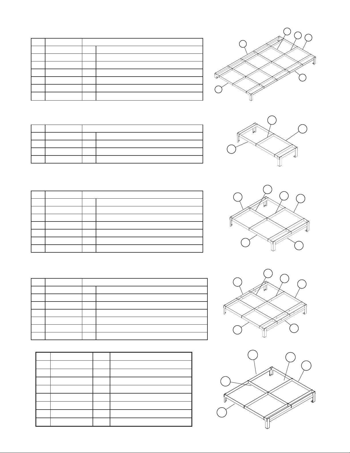
Lang Manufacturing Searail Assembly continued
Part No. Qty Description
50302-300-1 SEARAIL ASSY 5’ {500} SK
A 50302-305 1 SEARAIL LH SIDE {ADD,RF & 500}
B 50302-306 1 SEARAIL RH SIDE {ADD,RF & 500}
C 50302-317 15 SEARAIL SIDE TO SIDE 12”
D 50302-315 4 SEARAIL FR TO BK {ADD,RF,500}
E 50302-309 2 SEARAIL FR & RR 5’
20109-04 10 SCREW THD MS SS 10-32X 3/8
20301-34 2 NUT HEX ACORN 10-32 S/S
D
C
B
E
E
A
Part No. Qty Description
50302-304-1 SEARAIL ASSY 1’ RT30 SK
A 50302-307 1 SEARAIL LH SIDE RT30
B 50302-308 1 SEARAIL RH SIDE RT30
C 50302-317 5 SEARAIL SIDE TO SIDE 12”
20109-04 6 SCREW THD MS SS 10-32X 3/8
Part No. Qty Description
50302-302-1 SEARAIL ASSY 2’ RT30/32 SK
A 50302-307 1 SEARAIL LH SIDE RT30
B 50302-308 1 SEARAIL RH SIDE RT30
C 50302-317 6 SEARAIL SIDE TO SIDE 12”
D 50302-316 1 SEARAIL FR TO BK RT30
E 50302-311 2 SEARAIL FR & RR 2’
20109-04 6 SCREW THD MS SS 10-32X 3/8
20301-34 2 NUT HEX ACORN 10-32 S/S
Part No. Qty Description
50302-295-1 SEARAIL ASSY RT30 DBL W/GRD SK
A 50302-307 1 SEARAIL LH SIDE RT30
B 50302-308 1 SEARAIL RH SIDE RT30
C 50302-314 3 SEARAIL SUPPORT RT30 W/GRIDDLE
D 50302-316 2 SEARAIL FR TO BK RT30
E 50302-313 2 SEARAIL FR&RR RT30 W/GRIDDLE
20109-04 8 SCREW THD MS SS 10-32X 3/8
20301-34 2 NUT HEX ACORN 10-32 S/S
C
B
A
D
E
A
C
B
E
D
E
A
C
B
E
Part No. Qty Description
P9-50302-302-2 1 SEARAIL ASSEMBLY - RTI30
A P9-50302-307-1 1 SEARAIL-LH SIDE-RTI30
B P9-50302-308-1 1 SEARAIL-RH SIDE-RTI30
E P9-50302-316-1 1 SEARAIL-FRT TO BCK-RI30
D P9-50302-311-1 2 SEARAIL-FRONT-RTI30
C P9-50302-317-2 4 SEARAIL-CROSS BRKT-RTI30
2C-20109-04 8 SCRW THD MS SS 10-32X3/8
2C-20301-34 2 NUT HEX ACORN 10-32 S/S
D
C
B
E
A
Page 20
STAR INTERNATIONAL HOLDINGS INC. COMPANY
Star - Holman - Lang - Wells - Bloomeld - Toastmaster
10 Sunnen Drive, St. Louis, MO 63143 U.S.A.
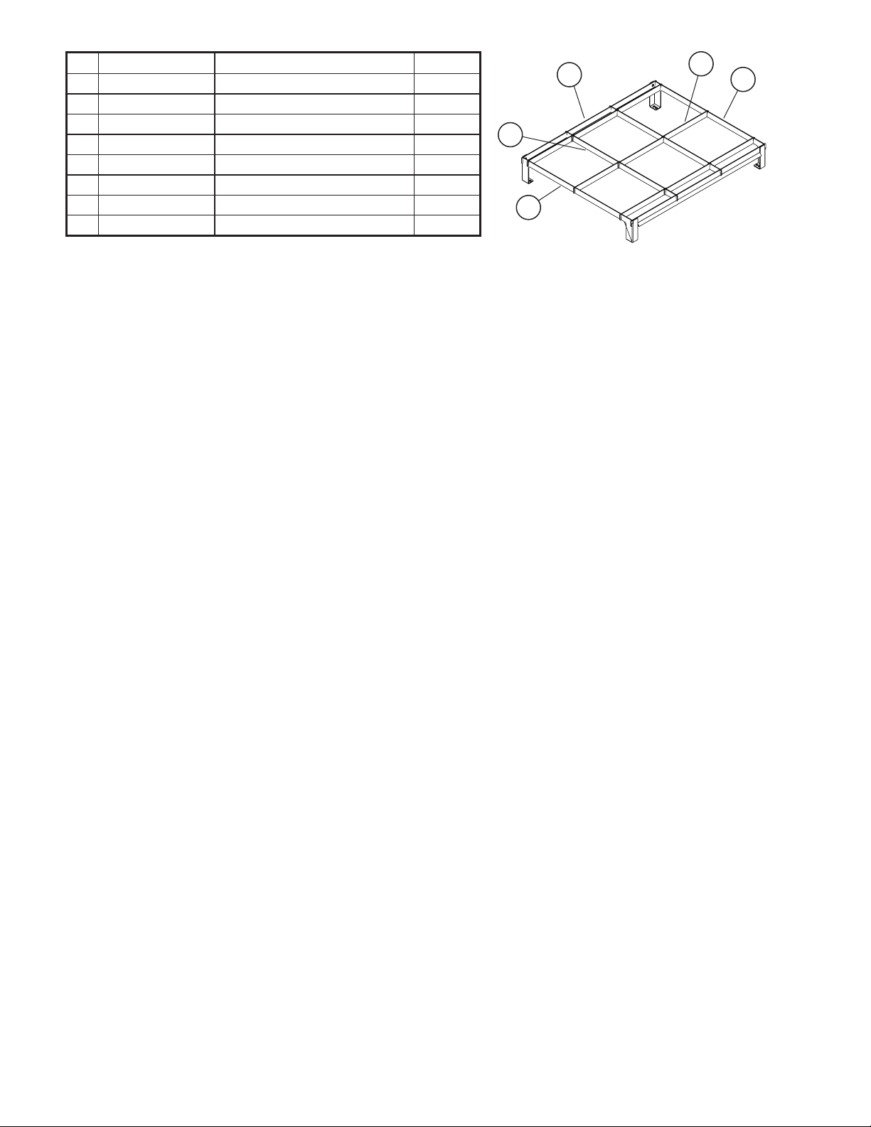
Part Number Description Quantity
P9-50302-297-2 SEARAIL ASSEMBLY - RTI36 1
A P9-50302-306-1 SEARAIL - LH SIDE - 36” 1
B P9-50302-305-1 SEARAIL - RH SIDE - 36” 1
C P9-50302-317-3 SEARAIL-CROSS BRKT-36” 9
D P9-50302-311-2 SEARAIL-FRT REAR-36” 1
E P9-50302-316-2 SEARAIL-FRT TO BACK-36” 2
2C-20109-04 SCRW THD MS SS 10-32X3/8 10
2C-20301-34 NUT HEX ACORN 10-32 S/S 2
D
C
B
E
A
 Loading...