

Page 1
Installation,
Operation, and
Maintenance Instructions
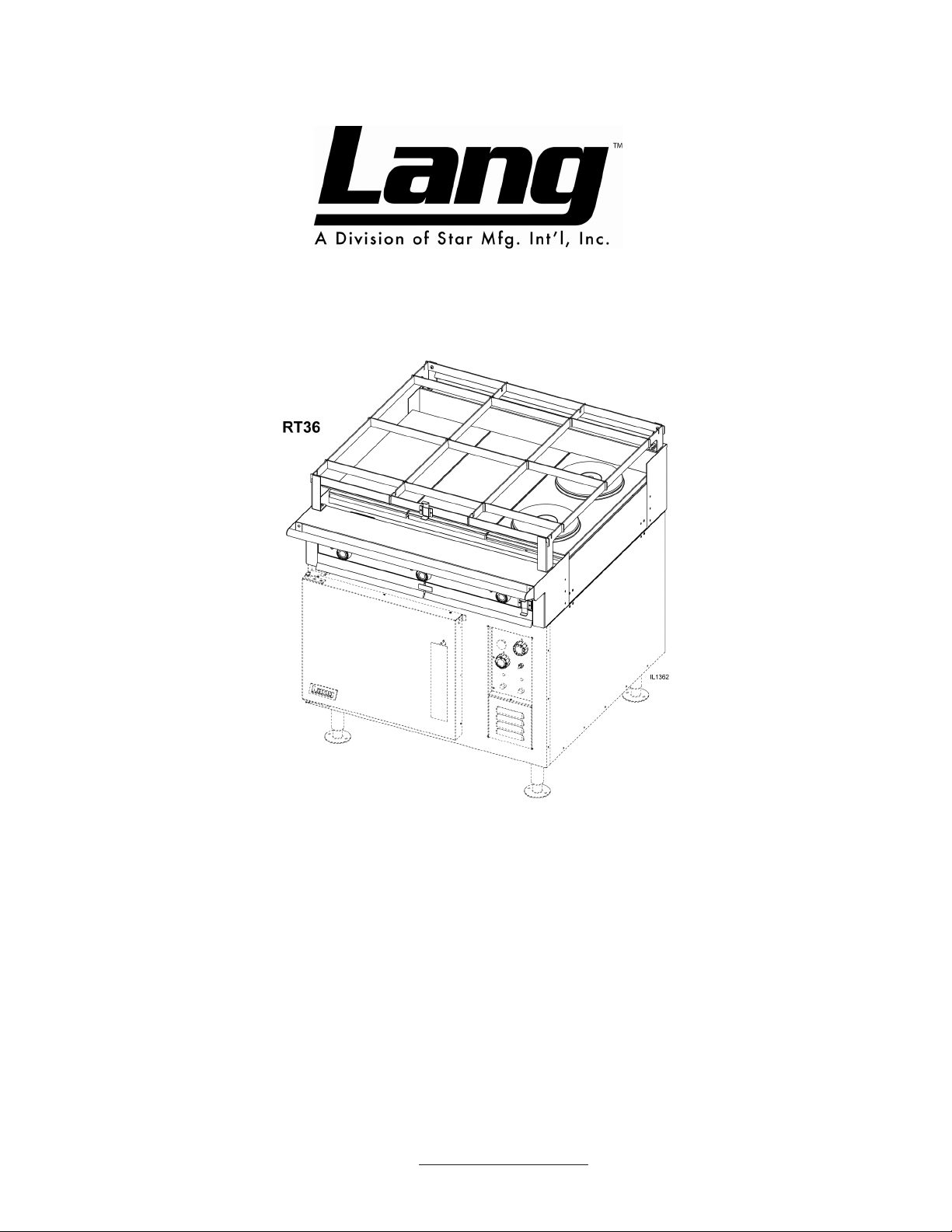
Range Top: RT36A, B, C, D, E, G
Star Manufacturing International 10 Sunnen Drive St. Louis, MO.63143-3800
Part Number: 2M-W1091 Ph: 314-781-2777 Fax: 314-781-2714
Rev.D
WWW.STAR-MFG.COM June 12, 2008
Page 2
THIS MANUAL MUST BE RETAINED FOR FUTURE REFERENCE.
READ, UNDERSTAND AND FOLLOW THE INSTRUCTIONS AND
WARNINGS CONTAINED IN THIS MANUAL.
FOR YOUR SAFETY
DO NOT STORE OR USE GASOLINE OR OTHER FLAMMABLE
VAPORS AND LIQUIDS IN THE VICINITY OF THIS OR ANY
OTHER APPLIANCE.
POST IN A PROMINENT LOCATION
INSTRUCTIONS TO BE FOLLOWED IN THE EVENT USER
SMELLS GAS. THIS INFORMATION SHALL BE OBTAINED BY
CONSULTING YOUR LOCAL GAS SUPPLIER. AS A MINIMUM,
TURN OFF THE GAS AND CALL YOUR GAS COMPANY AND
YOUR AUTHORIZED SERVICE AGENT. EVACUATE ALL
PERSONNEL FROM THE AREA.
WARNING: IMPROPER INSTALLATION, ADJUSTMENT,
ALTERATION, SERVICE OR MAINTENANCE CAN CAUSE
PROPERTY DAMAGE, INJURY OR DEATH. READ THE
INSTALLATION, OPERATING AND MAINTENANCE
INSTRUCTIONS THOROUGHLY BEFORE INSTALLING OR
SERVICING THIS EQUIPMENT.
Model # Purchased From
Serial # Location:
Date Purchased Date Installed
Purchase Order # For Service, Call
2
Page 3

Table of Contents
CHAPTER PAGE
Table Of Contents ....................................................................................................................... 3
Equipment Description ................................................................................................................ 6
Unpacking ................................................................................................................................... 7
Installation ................................................................................................................................... 8
Initial Start-Up ............................................................................................................................. 10
Operation .................................................................................................................................... 11
Maintenance & Cleaning Procedures ........................................................................................ 12
Troubleshooting .......................................................................................................................... 13
Wiring Diagram ........................................................................................................................... 14
Exploded View & Parts List......................................................................................................... 15 - 17
Sea Rails Exploded View & Parts List ........................................................................................ 18 - 19
3
Page 4
Warnings
THE RANGE WEIGHS 410 LBS. (186 KILOGRAMS).
FOR SAFE HANDLING, INSTALLER SHOULD OBTAIN
HELP AS NEEDED, OR EMPLOY APPROPRIATE
MATERIALS HANDLING EQUIPMENT (SUCH AS A
FORKLIFT, DOLLY, OR PALLET JACK) TO REMOVE
THE UNIT FROM THE SKID AND MOVE IT TO THE
PLACE OF INSTALLATION.
CAUTION: ANY STAND, COUNTER OR OTHER DEVICE ON
WHICH RANGE WILL BE LOCATED MUST BE
DESIGNED TO SUPPORT THE WEIGHT OF THE
RANGE (410 LBS.).
SHIPPING STRAPS ARE UNDER TENSION AND CAN
SNAP BACK WHEN CUT.
THIS APPLIANCE MUST BE GROUNDED AT THE
TERMINAL PROVIDED. FAILURE TO GROUND THE
APPLIANCE COULD RESULT IN ELECTROCUTION
AND DEATH.
WARNING: INSTALLATION OF THE UNIT MUST BE DONE BY
PERSONNEL QUALIFIED TO WORK WITH
ELECTRICITY AND PLUMBING. IMPROPER
INSTALLATION CAN CAUSE INJURY TO
PERSONNEL AND/OR DAMAGE TO EQUIPMENT.
UNIT MUST BE INSTALLED IN ACCORDANCE WITH
ALL APPLICABLE CODES.
The data plate is located right of Range top controls.
The range voltage, wattage, serial number, wire size,
and clearance specifications are on the data plate.
This information should be carefully read and
understood before proceeding with the installation.
NOTICE: The installation of any components such as a vent
hood, grease extractors, and/or a fire extinguisher
system, must conform to the applicable National,
State and locally recognized installation standards.
During the first few hours of operation, you may
notice a small amount of smoke coming from the
unit, and a faint odor. This is normal for a new range
and will disappear after the first few hours of use.
ALWAYS KEEP THE AREA NEAR THE APPLIANCE
FREE FROM COMBUSTIBLE MATERIALS.
CAUTION: KEEP FLOOR IN FRONT OF EQUIPMENT CLEAN
AND DRY. IF SPILLS OCCUR, CLEAN IMMEDIATELY,
TO AVOID THE DANGER OF SLIPS OR FALLS.
4
Page 5
Warnings
WARNING KEEP WATER AND SOLUTIONS OUT OF CONTROLS.
NEVER SPRAY OR HOSE CONTROL CONSOLE,
ELECTRICAL CONNECTIONS, ETC.
CAUTION MOST CLEANERS ARE HARMFUL TO THE SKIN, EYES,
MUCOUS MEMBRANES AND CLOTHING. WEAR RUBBER
GLOVES, GOGGLES/FACE SHIELD AND PROTECTIVE
CLOTHING. CAREFULLY READ THE WARNING AND
FOLLOW THE DIRECTIONS ON THE LABEL OF THE
CLEANER.
NOTICE Service on this or any other Lang appliance must be
performed by qualified personnel only. Consult your Lang
Authorized Service Agent Directory. You can call our toll
free number 1-800-807-9054 or visit our website
WWW.STAR-MFG.COM for the service agent nearest you.
WARNING BOTH HIGH AND LOW VOLTAGES ARE PRESENT INSIDE
THIS APPLIANCE WHEN THE UNIT IS PLUGGED/WIRED
INTO A LIVE RECEPTACLE. BEFORE REPLACING ANY
PARTS, DISCONNECT THE UNIT FROM THE ELECTRIC
POWER SUPPLY.
CAUTION USE OF ANY REPLACEMENT PARTS OTHER THAN
THOSE SUPPLIED BY STAR OR THEIR AUTHORIZED
DISTRIBUTORS CAN CAUSE BODILY INJURY TO THE
OPERATOR AND DAMAGE TO THE EQUIPMENT. THIS
WILL VOID ALL WARRANTIES.
5
Page 6
Installation
Model: RT36
Electric Range Top
Exterior
The range dimensions are 8” (20.3 cm) high, 38” (96.5cm) deep, and 36” (91.5cm) wide.
The sides, bottom, and rear wall are constructed of stainless steel.
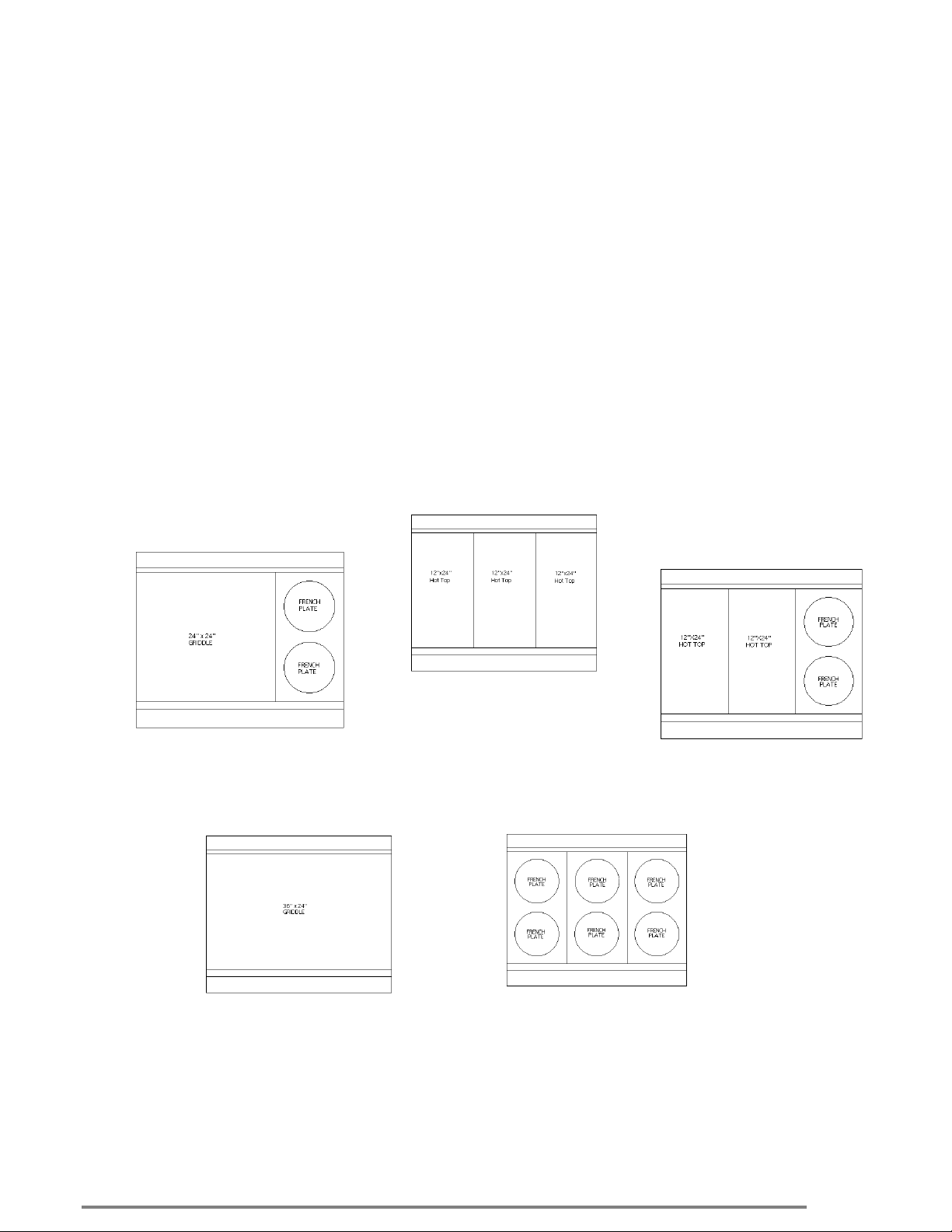
The range surface can come in 5 different configurations.
Controls
The RT36 Series Range is available with various controls depending upon model number. Shown below
are layouts of each top configuration with its proper model number and a brief description of the controls.
The RT36 provides three (3) options for the bottom of the range. A standard bake oven, convection oven,
or just as a range top.
RT36-ATA
One 24”x24” griddle controlled by
Two (2) 450°F thermostats and
Two (2) French plates controlled by
two 6-heat switches.
Three (3) Hot Tops controlled by
Three (3) 850°F thermostats.
RT36-ATD
One 36”x24” Griddle controlled by one 450°F
thermostat.
RT36-ATB
Two 12”x24” Hot tops
controlled by two (2) 850°F
thermostats and two (2) French
plates controlled by two (2) 6heat switches.
RT36-ATE
Six French plates controlled by six 6-heat
switches.
RT36-ATC
6
Page 7

Receiving the Range
Upon receipt, check for freight damage, both visible and concealed.
Note visible damage on the freight bill at the time of delivery and require
the carrier's agent to sign the freight bill. Concealed loss or damage
means loss or damage, which does not become apparent until the
merchandise has been unpacked. If concealed loss or damage is
discovered upon unpacking, make a written request for inspection by
the carrier's agent within 15 days of delivery. Keep all packing material
for inspection. Do not return damaged merchandise to STAR
Manufacturing Company. File your claim with the carrier.
Location
Prior to un-crating, move the range as near its intended location as
practical. The crating will help protect the unit from the physical
damage normally associated with moving it through hallways and
doorways.
Un-crating
The range will arrive completely assembled inside a wood frame
covered by cardboard box and strapped to a skid. Remove the
cardboard cover, cut the straps and remove the wood frame.
Installation
RANGE WEIGHS 410 LBS (186 kilograms). FOR SAFE
HANDLING, INSTALLER SHOULD OBTAIN HELP AS
NEEDED, OR EMPLOY APPROPRIATE MATERIALS
HANDLING EQUIPMENT (SUCH AS A FORKLIFT,
DOLLY, OR PALLET JACK) TO REMOVE THE UNIT
FROM THE SKID AND MOVE IT TO THE PLACE OF
INSTALLATION.
CAUTION ANY STAND, COUNTER OR OTHER DEVICE ON WHICH
RANGE WILL BE LOCATED MUST BE DESIGNED TO
SUPPORT THE WEIGHT OF THE OVEN (410 LBS.).
SHIPPING STRAPS ARE UNDER TENSION AND CAN
SNAP BACK WHEN CUT.
Remove range from skid and place in intended location.
INSTALLING THE LEGS
Legs or Casters are available and must be specified upon ordering.
To install the 6-inch legs, remove the legs from the range packing,
place some cardboard on the floor and gently tip the range onto its
back. Fasten the legs into the threaded holes provided and then gently
flip the oven onto its legs.
To install the 6-inch casters, remove the casters from the oven cavity,
place some cardboard on the floor and gently tip the range onto its
back. Attach the casters to the adapter plates. Install the four adapter
plates (one in each corner with the flange pointed toward the oven).
Gently tip the oven onto its casters.
7
Page 8

Installation
DANGER THIS APPLIANCE MUST BE GROUNDED AT THE
TERMINAL PROVIDED. FAILURE TO GROUND THE
APPLIANCE COULD RESULT IN ELECTROCUTION AND
DEATH.
WARNING INSTALLATION OF THE UNIT MUST BE DONE BY
PERSONNEL QUALIFIED TO WORK WITH ELECTRICITY
AND PLUMBING. IMPROPER INSTALLATION CAN CAUSE
INJURY TO PERSONNEL AND/OR DAMAGE TO
EQUIPMENT. UNIT MUST BE INSTALLED IN
ACCORDANCE WITH ALL APPLICABLE CODES.
The data plate is located right of range top controls. The
oven voltage, wattage, serial number, wire size, and
clearance specifications are on the data plate. This
information should be carefully read and understood
before proceeding with the installation.
NOTICE The installation of any components such as a vent hood,
grease extractors, fire extinguisher systems, must
conform to their applicable National, State and locally
recognized installation standards.
Electrical Connection
Make all electrical connections in accordance with local codes or in the
absence of local codes with NFPA No. 70 latest edition (in Canada use:
CSA STD. C22.1).
Place spacers, (i.e. 2x4 wood block not supplied) at the front and rear of
the oven top.
Place the range top on the spacers that are located on top of the oven.
The six wire leads that supply electricity to the cook top are bundled
under the front of the top. Route the six wires through the bushing
provided in the oven top.
Align the four locating pins in the bottom corner of the top with the four
holes in each corner of the oven top.
Remove the spacers and lower the top onto the oven.
MAKE SURE THE SIX WIRE LEADS TO SUPPLY
CAUTION
WARNING:
The range can now be connected to power.
CAUTION
Use the wiring diagram provided in this manual for determining the connections of the cook top
wires to the oven terminal block.
ELECTRICITY TO THE RANGE TOP ARE NOT CRIMPED
BETWEEN THE OVEN AND RANGE TOP. FAILURE TO
COMPLY WILL RESULT IN DAMAGE TO EQUIPMENT.
TURN OFF THE MAIN POWER SUPPLY TO THE RANGE
AT THE SOURCE PRIOR TO CONNECTING POWER TO
THE RANGE. FAILURE TO COMPLY MAY RESULT IN
SERIOUS INJURY AND OR DEATH.
BE SURE THE POWER SUPPLY VOLTAGE
MATCHES THE VOLTAGE SPECIFIED ON THE
NAMEPLATE LOCATED ON THE FRONT OF THE
RANGE. FAILURE TO COMPLY MAY RESULT IN
PERSONAL INJURY AND/OR DAMAGE TO
EQUIPMENT
8
Page 9

Electrical Connection
The following table and illustrations provide the voltage and kilowatts necessary to operate the
range and oven.
Electrical Specifications
Range style
Range Top
Only
W / Conv.
Oven
W / Bake
Oven
Three Phase with Oven Single Phase with Oven
Total
k.W.
15.0
21.6
21.0
208 Volt 240 Volt 480 Volt 208 V 240 V
L1 L2 L3 L1 L2 L3 L1 L2 L3 L1 L2
41.7 41.7 41.7 36.1 36.1 36.1 18.1 18.1 18.1 72.1 62.5
48.3 69.2 62.5 41.9 59.9 54.1 20.5 29.5 27.1 103.8 90.0
45.8 66.7 62.5 39.7 57.8 54.1 19.9 28.9 27.1 101.0 87.5
Installation
Three Phase Single Phase
9
Page 10

Installation
Hot Plates
To "dry out" the hot plate, set the thermostat dial at 250°F and turn on the
power switch. Allow unit to cycle at least 15 minutes at this heat level. Reset
the thermostat to 350°F allowing the same time. Then reset the thermostat to
450°F allowing the same time. Continue doing this until you reach 850°F then
allow the unit to maintain this temperature for a minimum of 4 hours. More
time may be required if the unit has to operate in a moist environment.
If the unit is out of use for three or more days, a one-hour preheat schedule
should be used, especially when exposed to high humidity and/or cool
temperatures.
French Plates
To “dry out” the Frenchplate, set the six-heat switch to the first setting and turn
on the power switch. Allow unit to cycle at least 15 minutes at this heat level.
Reset the six-heat switch to position 2 and allow the same time. Reset the
six-heat switch to position 3 and allow the same time. Continue doing this
until you reach position 6 then allow the unit to maintain the temperature for a
minimum of 4 hours. More time may be required if the unit has to operate in a
moist environment.
If the unit is out of use for three or more days, a one-hour preheat schedule
should be used, especially when exposed to high humidity and/or cool
temperatures.
Griddles
To “dry out” the griddle, set the thermostat to 250°F and turn on the power
switch. Allow the unit to cycle at least 15 minutes at this heat level. Reset the
thermostat to 350°F allow the same time. Reset the thermostat to 450°F and
allow the unit to maintain the temperature for a minimum of 4 hours. More
time may be required if the unit has to operate in a moist environment.
If the unit is out of use for three or more days, a one-hour preheat schedule
should be used, especially when exposed to high humidity and/or cool
temperatures.
NOTICE During the first few hours of operation you may notice a
small amount of smoke coming off the range, and a faint
odor from the smoke. This is normal for a new range and
will disappear after the first few hours of use.
10
Page 11

ALWAYS KEEP THE AREA NEAR THE APPLIANCE
FREE FROM COMBUSTIBLE MATERIALS.
CAUTION KEEP FLOOR IN FRONT OF EQUIPMENT CLEAN AND
DRY. IF SPILLS OCCUR, CLEAN IMMEDIATELY, TO
AVOID THE DANGER OF SLIPS OR FALLS.
RANGE TOP
Consists of the various top arrangements, depending on specific model
purchased:
12" x 24" hot plate controlled by high temperature thermostats.
Temperature ranges from 0°F-850°F. Recommended: Stock pots and
heavy kettle work.
Round French Plates, controlled by indicating type 6-heat switch.
Temperature ranges from 0°F-750°F. Recommended: Light duty sauce
pans and small stockpots. Not Recommended: Heavy stock pots, or heavy
urns, or kettles.
36" x 24" or 24" x 24" grill plates, controlled by thermostats. Temperature
ranges from 0°F-450°F. Recommended: All heavy and light frying. Set the
thermostat dial at the desired temperature. The red pilot light will be on until
the desired temperature is reached. The pilot light indicates that the plate is
heating.
Installation
11
Page 12

Maintenance and Cleaning
Cleaning
WARNING KEEP WATER AND SOLUTIONS OUT OF
CONTROLS. NEVER SPRAY OR HOSE
CONTROL CONSOLE, ELECTRICAL
CONNECTIONS, ETC.
CAUTION MOST CLEANERS ARE HARMFUL TO THE SKIN,
EYES, MUCOUS MEMBRANES AND CLOTHING. WEAR
RUBBER GLOVES, GOGGLES OR FACE SHIELD AND
PROTECTIVE CLOTHING. CAREFULLY READ THE
WARNING AND FOLLOW THE DIRECTIONS ON THE
LABEL OF THE CLEANER TO BE USED.
The range should be thoroughly cleaned at least once a week in addition to
the normal daily cleaning to insure against the accumulation of foreign
material.
CAUTION Any oven cleaner used should be marked "Safe On
Aluminum".
Keep-drip pans under the range top plates clean.
Keep the hotplate and griddle surfaces clean.
Outside of the range and top should be kept clean.
Electric equipment is inherently clean and sanitary, but may become
unsanitary if dirt is allowed to accumulate on it. Take advantage of the
clean, sanitary features of electric equipment, give it the regular attention
that it deserves the same as any other highly perfected machinery, to insure
best results and continued high operating efficiency.
CALIBRATION
Calibration Check
Place thermometer in the center of oven cavity.
Set thermostat to 350°F and place both 3-heat switches in the “HIGH”
position.
Allow the oven to Preheat for at least half an hour.
NOTE
Cycle on temperatures and cycle off temperatures for 3 cycles. (Red
indicator light indicates when oven is calling for heat)
After 3 cycles average the temperature. ( Add all six temperatures and
divide by 6)
Calibration Adjustment
A 1/16” flat blade screwdriver with a 2” shaft is required to make
adjustments to the thermostat.
Maintain the oven temperature at 350°F.
Without turning the thermostat, remove the knob.
Locate the adjustment screw at the base of the shaft and insert the
screwdriver.
Hold the shaft and turn the screwdriver counter clockwise to increase the
temperature and clockwise to decrease the temperature. (1/8 of a turn will
move the temperature 5-7 °F in either direction).
Reinstall the oven knob and recheck the oven temperature.
12
Page 13

Troubleshooting
Troubleshooting
Troubleshooting is not an exact science. Several factors may play a part in why your machine is not operating
correctly. The following symptoms are a general idea of what may be causing the malfunction and should not be
considered the complete answer to the situation that you have with your machine. Here are some of the
possible problems you may encounter and possible solutions to those problems.
Symptom Possible Cause
Hotplate will not heat No power to Unit
Defective Thermostat
Defective element
French plate will not heat No power to Unit
Failed 6-heat switch
Failed element
Griddle plate will not heat No power to Unit
Failed Thermostat
Failed element
TESTS
NOTICE: Service on this or any other Lang appliance must be
performed by qualified personnel only. Consult your
Lang Authorized Service Agent Directory. You can call
our toll free number 1-800-807-9054 or visit our website
WWW.STAR-MFG.COM for the service agent nearest you.
WARNING: BOTH HIGH AND LOW VOLTAGES ARE PRESENT
INSIDE THIS APPLIANCE WHEN THE UNIT IS
PLUGGED/WIRED INTO A LIVE RECEPTACLE. BEFORE
REPLACING ANY PARTS, DISCONNECT THE UNIT FROM
THE ELECTRIC POWER SUPPLY.
If an item on the list is followed by an asterisk (*), the work should be done by a
factory authorized service representative.
Possible Cause Test
Failed thermostat Verify calibration
Failed element
Failed 6-heat switch
USE OF ANY REPLACEMENT PARTS OTHER THAN
THOSE SUPPLIED BY STAR OR THEIR AUTHORIZED
CAUTION
DISTRIBUTORS CAN CAUSE BODILY INJURY TO THE
OPERATOR AND DAMAGE TO THE EQUIPMENT AND
WILL VOID ALL WARRANTIES.
Remove the wires and check for continuity
across the element*
Call factory or consult service manual for
proper tests
13
Page 14

Range Top Wiring
GRIDDLE HOT TOP FRENCH PLATE
14
1. Griddle and Top Plate Element
2. Pilot Light
3. 450°F Griddle thermostat
4. Circuit breakers
5. French plate
6. 6-Heat switch
7. Hot Top
8. 850°F Hot Top thermostat.
Page 15

Page 16

SK2265 Rev. A 6/12/08
Model:
36" Range Top
Old Style Sea Rails
22
21
20
18
19
23
24
25
26
3
4
5
6
7
8
9
10
11
13
14
15
12
16
17
1
2
Marine Application
12
4
16
Page 17

PARTS LIST April 5, 2010, Rev D
Model No: RT36A, RT36B, RT36C, RT36D, RT36E, RT36F, RT36G
COMMERCIAL & MARINE ELECTRIC RANGE TOP
Fig No Part No Qty Description Application
1 P9-50401-09 1 GROOVED RANGE PLATE ASSY 1 X 2’ ALL RT36A V
2 P9-50401-02 1 SMOOTH RANGE PLATE ASSY 1/2 X 2’ ALL RT36A VM
P9-50401-03
3
P9-50401-11 GROOVED RANGE PLATE ASSY 1/2 X 3’ ALL RT36D V
P9-50403-10 RANGE PLATE ASSY 1 X 3’ RT36D1
P9-50302-301
4
P9-50302-303-1 SEARAIL ASSY 1’ {ADD} SK ALL RT36A AND RT36C VM
2N-11120-12
2N-11120-13
5
2N-11120-14
2N-11120-18 ELMNT TK 380V 2000W RT36E-380V
P9-50300-82-1
6
P9-50300-83 2 EGO FRENCH HOT PLATE RT36F-480VM
PS-11010-341
7
PS-11010-351 HOTPLATE 240V 5000W CAST RT36B-240V, RT36C-240V & VM, RT36F-240VM
PS-11010-361 HOTPLATE 480V 5000W CAST
8 2C-21003-02 10 SCRW SECRTY 1/4-20 2-EAR RT36B-480VCP
9 P9-RF21-820 2 HOT TOP HLDER ASY CORR. PKG RT36B-480VCP
2E-30304-09
10
2T-30402-08
2T-30402-23
P9-RF21-304
11
P9-RF21-305 CONTROL PANEL C&G ALL RT36C AND RT36G
P9-RF21-306 CONTROL PANEL A&D ALL RT36A AND RT36D
12 Y9-50300-63 1 MARINE PAN LATCH ASSY
P9-70701-35 1 KNOB ASSY 850° B RT36F
P9-70701-41
13
Y9-70701-16
SMOOTH RANGE PLATE ASSY 1/2 X 3’ ALL RT36D VM
1
SEARAIL ASSY 3’ {RF&500} ALL RT36E-VM, RT36F-VM
1
2
ELMNT TK 208V 2600W
6 RT36E-208V & VM
2
ELMNT TK 240V 2600W
4 RT36F-240V
6 RT36E-240V & VM
2
ELMNT TK 480V 2600W
6
1
EGO PLATE FRM ASY PHANT
3 ALL RT36E
2
HOTPLATE 208V 5000W CAST
3
2
SWTROT 6 HEAT+OFF208/240V
6 ALL RT36E
2
STAT ADJ 450o 72 C/T
3 ALL RT36D
3
STAT ADJ 850° 48C/T NAK
2 ALL RT36C
1 ALL RT36F
CONTROL PANEL H ALL RT36E
1
3
KNOB ASSY 6 HEAT EGOTK
4 ALL RT36A AND RT36C, RT36F
6 ALL RT36E
2
KNOB ASSY 450o A
3 ALL RT36D; ALL RT36B; RT36C-208 V AND VM, 240 V AND VM
RT36A-208V & VM, RT36C-208V
RT36A-240V & VM, RT36C-240V & VM
RT36A-440VM, 480V & VM, RT36C-440VM, 480V & VM
RT36E-440VM, 480V & VM
RT36A-208V & VM, 240V, ALL RT36C
RT36C-208V
RT36B-208V & VM
RT36B-440VM, 480V & VM, RT36C-440VM, 480V & VM, RT36F-440VM
& 480VM
RT36A-208V & VM, 240V, 440VM, 480V & VM, RT36B-440VM, ALL
RT36C
ALL RT36A
ALL RT36B
ALL RT36A VM, ALL RT36B VM & VCP, ALL RT36C VM, RT36D-208VM
& 240VM & 440VM, ALL RT36E VM
ALL RT36B AND RT36D
ALL RT36A; RT36C-440 VM,480 V AND VM
1
IMPORTANT: WHEN ORDERING, SPECIFY VOLTAGE OR TYPE GAS DESIRED PAGE
3
INCLUDE MODEL AND SERIAL NUMBER OF
Some items are included for illustrative purposes only and in certain instances may not be available.
Star International Holdings, Inc. Company
Page 18

PARTS LIST April 5, 2010, Rev D
Model No: RT36A, RT36B, RT36C, RT36D, RT36E, RT36F, RT36G
COMMERCIAL & MARINE ELECTRIC RANGE TOP
Fig No Part No Qty Description Application
2J-31601-01
14
2J-31601-02
14 Y9-31601-02-1 3 PILOT LT 480V W/TIN CLIP PHANT RT36D 480 SUB
P9-RF21-415-1 2 PAN ASSY (304 S/S)
15
PS-60102-W1232 1 RF21 MARINE PAN ASY-RIGHT
16 P9-50300-44-1 1 GRAB BAR ASSY 36 RANGE
17 M9-60102-290 1 MARINE PAN ASSY - A/L
18 P9-RF21-803 1 WINDOW - CP RF21 RT36B-480VCP
19 P9-RF21-800 1 DOOR ASSY - CP RT36B-480VCP
20 P9-50306-25
21 P9-50306-33
P9-50300-22
22
P9-50300-43
P9-50300-41
23
P9-50300-43 1 480 V 3/16 BULB HOLDER ALL RT36G
24 P9-50300-42
2N-11010-09
2N-11010-21
25
2N-11010-23
2N-11010-25
2
PILOT LT 250V 6LEAD BLK
3 RT36B-208V & VM, 240V & VM, RT36D-208V & VM, 240V & VM
2
PILOT LT 480V 6LEAD BLK
3 RT36B-440VM, 480V & VM, RT30D-440VM & 480V
2
WIRE BRACKET ASSY TILT-UP
3 ALL RT36D
1 ALL RT36G
3
ELEM TERMINAL GUARD
2 ALL RT36A
1 ALL RT36G
2
208-240 V 3/16 BULB HOLDER
3 ALL RT36D 208, 240 V AND VM
2
480 V 3/16 BULB HOLDER
3 ALL RT36D 440VM, 480 V AND VM
1 ALL RT36D 440VM
2
ELEM PAN ASSY (W/SNOUT) 5KW
3 RT36D 208, 240 V AND VM
2
ZIG ZAG ASSY (W/SNOUT) 5KW
3 ALL RT36D
1 ALL RT36G
2
ELMNT T/P 208V 2KW O/S
3 RT36D 208 V AND VM
2
ELMNT T/P 240V O/S 2KW
3 RT36D 240 V AND VM
2
ELMNT T/P 480V O/S 2KW
3 RT36D 480 V AND VM, 440 VM ;480 SUB
1 RT36G
3
ELMNT T/P 380V O/S 2KW
1 RT36G-380VM
RT36A-208V & VM, 240V & VM, RT36C-208V & VM, 240V & VM
RT36A-440VM, 480V & VM, RT36C-440VM, 480V & VM
ALL RT36A V, ALL RT36B V, ALL RT36C V, RT36D-208V & 240V, ALL
RT36E V
ALL RT36A VM, ALL RT36B VM, ALL RT36C VM, RT36D-208VM &
240VM & 440VM, ALL RT36E VM
ALL RT36A VM, ALL RT36B VM, ALL RT36C VM, ALL RT36D VM, ALL
RT36E VM
ALL RT36A VM, ALL RT36B VM, ALL RT36C VM, ALL RT36D VM,ALL
RT36E
ALL RT36A
ALL RT36D
ALL RT36A 208, 240 V AND VM
ALL RT36A 440VM, 480 V AND VM
RT36A 208, 240 V AND VM
ALL RT36A
RT36A 208 V AND VM
RT36A 240 V AND VM
RT36A 480 V AND VM, 440 VM
RT36D-380VM
2
IMPORTANT: WHEN ORDERING, SPECIFY VOLTAGE OR TYPE GAS DESIRED PAGE
3
INCLUDE MODEL AND SERIAL NUMBER OF
Some items are included for illustrative purposes only and in certain instances may not be available.
Star International Holdings, Inc. Company
Page 19

PARTS LIST April 5, 2010, Rev D
Model No: RT36A, RT36B, RT36C, RT36D, RT36E, RT36F, RT36G
COMMERCIAL & MARINE ELECTRIC RANGE TOP
2N-11010-10
2N-11010-22
26
2N-11010-24
2N-11010-26
NI 2E-30500-08 1 TRM BLOCK 2 POLE SMALL 95 RT36A-440VM, 480V & VM, RT36C-440VM, 480V & VM
NI 2E-30500-09 1 TRM BLOCK 3 POLE SMALL 95 RT36B-440VM, 480V & VM, RT36D-440VM, 480V & VM
NI 2E-31800-01 6 CB 250V50A 1 POLE CRLNGSW
2
ELMNT T/P 208V 3KW I/S
3 RT36D 208 V AND VM
2
ELMNT T/P 240V I/S 3KW
3 RT36D 240 V AND VM
2
3 RT36D 480 V AND VM, 440 VM, 480 SUB
ELMNT T/P 480V I/S 3KW
1 RT36G
3
ELMNT T/P 380V I/S 3KW
1 RT36G-380VM
RT36A 208 V AND VM
RT36A 240 V AND VM
RT36A 480 V AND VM, 440 VM
RT36D-380VM
RT36A-208V & VM, 240V & VM, RT36B-208V & VM, 240V & VM,
RT36C-208V & VM, 240V & VM, RT36D-208V & VM, 240V & VM,
RF36E-208V & VM, 240V & VM
3
IMPORTANT: WHEN ORDERING, SPECIFY VOLTAGE OR TYPE GAS DESIRED PAGE
3
INCLUDE MODEL AND SERIAL NUMBER OF
Some items are included for illustrative purposes only and in certain instances may not be available.
Star International Holdings, Inc. Company
Page 20

STAR MANUFACTURING
10 Sunnen Drive, St. Louis, MO 63143 U.S.A.
(800) 807-9054 (314) 781-2777
Parts & Service (800) 807-9054
www.star-mfg.com
 Loading...