

Page 1

Installation,
Operation, and
Maintenance Instructions
Range Top with Convection Oven
Model RT30S (CF)
RT30A-208VCF
Star Manufacturing International 10 Sunnen Drive St. Louis, MO.63143-3800
Part Number: 2M-W1093 Ph: 314-781-2777 Fax: 314-781-2714
Rev.A
WWW.STAR-MFG.COM June 18, 2010
Page 2
THIS MANUAL MUST BE RETAINED FOR FUTURE REFERENCE. READ, UNDERSTAND
AND FOLLOW THE INSTRUCTIONS AND WARNINGS CONTAINED IN THIS MANUAL.
DANGER
WARNING
CAUTION
NOTICE
POTENTIALLY HAZARDOUS SITUATION, WHICH, IF NOT
AVOIDED, COULD RESULT IN DEATH.
POTENTIALLY HAZARDOUS SITUATION WHICH, IF NOT
AVOIDED, COULD RESULT IN DEATH OR SERIOUS INJURY.
POTENTIALLY HAZARDOUS SITUATION WHICH, IF NOT
AVOIDED, MAY RESULT IN MINOR OR MODERATE INJURY.
Helpful operation and installation instructions and tips are
present.
FOR YOUR SAFETY
DO NOT STORE OR USE GASOLINE OR OTHER FLAMMABLE VAPORS AND LIQUIDS IN
THE VICINITY OF THIS OR ANY OTHER APPLIANCE.
POST IN A PROMINENT LOCATION
INSTRUCTIONS TO BE FOLLOWED IN THE EVENT USER SMELLS GAS. THIS
INFORMATION SHALL BE OBTAINED BY CONSULTING YOUR LOCAL GAS SUPPLIER.
AS A MINIMUM, TURN OFF THE GAS AND CALL YOUR GAS COMPANY AND YOUR
AUTHORIZED SERVICE AGENT. EVACUATE ALL PERSONNEL FROM THE AREA.
WARNING: IMPROPER INSTALLATION, ADJUSTMENT, ALTERATION, SERVICE OR
MAINTENANCE CAN CAUSE PROPERTY DAMAGE, INJURY OR DEATH. READ THE
INSTALLATION, OPERATING AND MAINTENANCE INSTRUCTIONS THOROUGHLY
BEFORE INSTALLING OR SERVICING THIS EQUIPMENT.
Model #: Purchased From:
Serial #: Location:
Date Purchased: Date Installed:
Purchase Order #: For Service, Call:
Page 3

Table of Contents
Chapter Page
TABLE OF CONTENTS....................................................................................................................3
READ FIRST ....................................................................................................................................4
EQUIPMENT DESCRIPTION...........................................................................................................6
UNPACKING ....................................................................................................................................7
INSTALLATION................................................................................................................................8
INITIAL START-UP...........................................................................................................................11
OPERATION.....................................................................................................................................12
MAINTENANCE & CLEANING PROCEDURES..............................................................................15
TROUBLE SHOOTING.....................................................................................................................16
PARTS LIST.....................................................................................................................................18
WIRING DIAGRAM...........................................................................................................................20
UL File# E8138 Rev New
3
Page 4
CAUTION
DANGER
WARNING
NOTICE
EACH UNIT WEIGHS 412 POUNDS (186.9 kg). FOR SAFE HANDLING,
INSTALLER SHOULD OBTAIN HELP AS NEEDED, OR EMPLOY APPROPRIATE
MATERIALS HANDLING EQUIPMENT (SUCH AS A FORKLIFT, DOLLY OR
PALLET JACK) TO REMOVE THE UNIT FROM THE SKID AND MOVE IT TO THE
PLACE OF INSTALLATION.
ANY STAND, COUNTER OR OTHER DEVICE ON WHICH RANGE WILL BE
LOCATED MUST BE DESIGNED TO SUPPORT THE WEIGHT OF THE RANGE.
SHIPPING STRAPS ARE UNDER TENSION AND CAN SNAP BACK WHEN CUT.
THIS APPLIANCE MUST BE GROUNDED AT THE TERMINAL PROVIDED.
FAILURE TO GROUND THE APPLIANCE COULD RESULT IN ELECTROCUTION
AND DEATH.
INSTALLATION OF THE UNIT MUST BE DONE BY PERSONNEL QUALIFIED TO
WORK WITH ELECTRICITY AND PLUMBING. IMPROPER INSTALLATION CAN
CAUSE INJURY TO PERSONNEL AND/OR DAMAGE TO EQUIPMENT. UNIT
MUST BE INSTALLED IN ACCORDANCE WITH ALL APPLICABLE CODES.
The data plate is located on the right side of the oven. The range voltages,
wattage, serial number, wire size and clearance specifications are on the data
plate. This information should be carefully read and understood before
proceeding with the installation.
The installation of any components such as a vent hood, grease extractors or
fire extinguisher systems must conform to their applicable National, State and
locally recognized installation standards.
During the first few hours of operation you may notice a small amount of
smoke coming from the range and a faint odor from the smoke. This is normal
for a new range and will disappear after the first few hours of use.
CAUTION
WARNING
CAUTION
NOTICE
ALWAYS KEEP THE AREA NEAR THE APPLIANCE FREE FROM
COMBUSTIBLE MATERIALS AND DO NOT OBSTRUCT F LOW OF
COMBUSTION OR VENTILATION AIR.
KEEP FLOOR IN FRONT OF EQUIPMENT CLEAN AND DRY. IF SPILLS
OCCUR, CLEAN IMMEDIATELY TO AVOID THE DANGER OF SLIPS OR FALLS.
KEEP WATER AND SOLUTIONS OUT OF CONTROLS. NEVER SPRAY OR
HOSE CONTROL CONSOLE, ELECTRICAL CONNECTIONS, ETC.
MOST CLEANERS ARE HARMFUL TO THE SKIN, EYES, MUCOUS
MEMBRANES AND CLOTHING. PRECAUTIONS SHOULD BE TAKEN TO WEAR
RUBBER GLOVES, GOGGLES OR FACE SHIELD AND PROTECTIVE
CLOTHING. CAREFULLY READ THE WARNINGS AND FOLLOW THE
DIRECTIONS ON THE LABEL OF THE CLEANER TO BE USED.
Never leave a chlorine sanitizer in contact with stainless steel surfaces longer
than 10 minutes. Longer contact can cause corrosion.
UL File# E8138 Rev New
4
Page 5
NOTICE
WARNING
CAUTION
Service on this or any other Lang appliance must be performed by qualified
personnel only. Consult your Lang Authorized Service Agent Directory. You
can call our toll free number 1-800-807-9054 or visit our website WWW.STAR-
MFG.COM for the service agent nearest you..
BOTH HIGH AND LOW VOLTAGES ARE PRESENT INSIDE THIS APPLIANCE
WHEN THE UNIT IS PLUGGED/WIRED INTO A LIVE RECEPTACLE. BEFORE
REPLACING ANY PARTS, DISCONNECT THE UNIT FROM THE ELECTRIC
POWER SUPPLY.
USE OF ANY REPLACEMENT PARTS OTHER THAN THOSE SUPPLIED BY
STAR OR THEIR AUTHORIZED DISTRIBUTORS CAN CAUSE BODILY INJURY
TO THE OPERATOR OR DAMAGE TO THE EQUIPMENT AND WILL VOID ALL
WARRANTIES.
UL File# E8138 Rev New
5
Page 6

Equipment Description
Exterior / Interior Construction
The range exterior dimensions are 30” Wide (76.2 cm), 35.25” High (89.5 cm), 28.5” Deep
(72.4 cm). The Top, Front, Back, and Sides are constructed of stainless steel with an
aluminized bottom.
The oven door comes standard with a window.
The door handle is constructed of Polycarbonate.
The oven cavity is insulated with high temperature insulation for efficiency and reduced
heat loss.
The oven cavity dimensions are 15” Wide (38.1 cm), 20” High (50.8 cm), 21” Deep (53.3
cm).
The oven is designed for five shelves and comes with five Chrome Plated Racks.
The interior of the oven is constructed of stainless steel.
Operation
The oven is a forced air convection oven with a vented oven cavity.
The air is driven by a 1/3 HP fan motor.
Controls
Range Top
Hot tops: One 850°F thermostat per section.
Griddle: One 450°F thermostat per section.
French Plate: One 6-heat switches per individual French Plate.
Oven
Icon driven (touch) panel allows for easy operation.
Complete computerized controls.
Pre-programmable product selections.
Independent shelf timers for each shelf.
Load control through use of Cooking Curves.
Shelf compensation for uniform baking.
Solid state temperature sensing and controls.
Dual-speed fan.
Manual-override controls.
Technical
Range operates as shipped on 208V or 240V (single or three phase) or 480V (three
phase). See data plate for electrical specifications.
The range can be shipped with a power cord and plug attached, but must be specified
upon ordering.
Floor space required is 42” wide (106.7 cm), 32.5” deep (82.6 cm).
The range weighs 412 lb (186.9 kg).
UL File# E8138 Rev New
6
Page 7

Unpacking
Receiving the Range
Upon receipt, check for freight damage, both visible and concealed. Visible
damage should be noted on the freight bill at the time of delivery and signed
by the carrier's agent. Concealed loss or damage means loss or damage
which does not become apparent until the merchandise has been unpacked.
If concealed loss or damage is discovered upon unpacking, make a written
request for inspection by the carrier's agent within 15 days of delivery. All
packing material should be kept for inspection. Do not return damaged
merchandise to Star Manufacturing Company. File your claim with the
carrier.
Location
Prior to un-crating, move the range as near to its intended location as
practical. The crating will help protect the unit from the physical damage
normally associated with moving it through hallways and doorways.
Un-crating
The range will arrive completely assembled inside a wood frame and strapped
to a skid. Cut the straps and remove the wood frame.
EACH UNIT WEIGHS 412 POUNDS (186.9 kg). FOR SAFE HANDLING,
INSTALLER SHOULD OBTAIN HELP AS NEEDED, OR EMPLOY
APPROPRIATE MATERIALS HANDLING EQUIPMENT (SUCH AS A
FORKLIFT, DOLLY, OR PALLET JACK) TO REMOVE THE UNIT FROM THE
CAUTION
SKID AND MOVE IT TO THE PLACE OF INSTALLATION.
ANY STAND, COUNTER OR OTHER DEVICE ON WHICH RANGE WILL BE
LOCATED MUST BE DESIGNED TO SUPPORT THE WEIGHT OF THE
RANGE. SHIPPING STRAPS ARE UNDER TENSION AND CAN SNAP
BACK WHEN CUT.
Remove range from skid and place in intended location.
UL File# E8138 Rev New
7
Page 8

DANGER
WARNING
NOTICE
Installation
THIS APPLIANCE MUST BE GROUNDED AT THE TERMINAL PROVIDED.
FAILURE TO GROUND THE APPLIANCE COULD RESULT IN
ELECTROCUTION AND DEATH.
INSTALLATION OF THE UNIT MUST BE DONE BY PERSONNEL
QUALIFIED TO WORK WITH ELECTRICITY AND PLUMBING. IMPROPER
INSTALLATION CAN CAUSE INJURY TO PERSONNEL AND/OR DAMAGE
TO EQUIPMENT. UNIT MUST BE INSTALLED IN ACCORDANCE WITH ALL
APPLICABLE CODES.
The data plate is located on the right hand side of the oven. Voltage,
wattage, serial number, wire size, and clearance specifications are on the
data plate. This information should be carefully read and understood
before proceeding with the installation.
The installation of any components such as a vent hood, grease
extractors and fire extinguisher systems must conform to their applicable
National, State and locally recognized installation standards.
Range Installation
The range will come pre-assembled with the casters already installed.
Electrical Connection
The electrical connection must be made in accordance with local codes or,
in the absence of local codes, with NFPA No. 70, latest edition (in Canada
use CSA STD. C22.1).
The electrical service entrance is provided by a 1-1/4-inch knockout at the
range back directly behind the control compartment. A grounding lug is
provided at the rear service entrance.
The R30S (PT) may have been purchased with a cord & plug kit. This kit
includes a 48” cord with a NEMA L15-30P plug.
Range Voltage
The Lang Model R30S range operates as shipped on either 208V or 240V
(single or three phase) and 480V (three phase). Amperages, kW rating and
phasing can be found in the wiring diagram section of this manual.
UL File# E8138 Rev New
8
Page 9
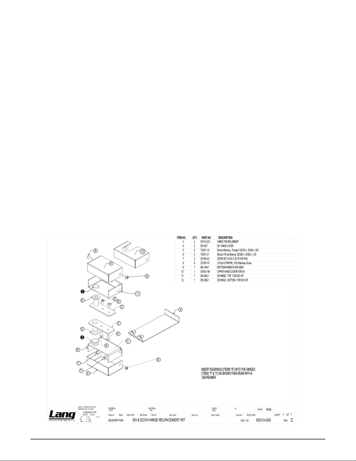
Reversing the door
1. Disconnect the oven from power.
2. Remove the top and bottom door hinge covers (4) by removing the two 10-32
Phillips head screws (8).
3. Remove the top door hinge bracket (1) from the oven by removing the two 1/420 Phillips head screws (7). The hinge should slide off of the door pin. This
will now be your right hand lower hinge.
4. Lift the door off of the bottom pin and set it aside.
5. Remove the bottom door hinge bracket (2) by removing the two 1/4-20 Phillips
head screws (7). This will now be your upper right hand hinge.
6. Remove the lower hinge mounting plate (9) by pulling it from behind the leg
pad adapter on the bottom of the oven.
7. Remove the two Phillips head screws in the bottom right corner of the oven
where the new hinge will be placed.
8. Slide the hinge mounting plate (9) into place and mount the hinge bracket (this
should be your old upper hinge) using two 1/4-20 (7) Phillips head screws.
9. Remove the two Phillips head screws in the upper right corner of the oven
where the new hinge will be placed.
10. Rotate the door 180° and slide the door pin into the bottom hinge bracket.
11. Slide the upper doo r hinge (1) onto the upper door pin and screw into place
using two 1/4-20 Phillips head screws.
12. Place the top and bottom door hinge covers (4) back on the oven using two
10-32 Phillips head screws (8).
Installation cont'd.
UL File# E8138 Rev New
9
Page 10

Ventilation and Clearances
Standard minimum clearance from combustible construction is as follows.
4” from side
4” from back
6” from floor
These ranges may be set directly, without legs, on a curbed base or non-
combustible floor.
If the range is set without legs on a non-combustible floor or a curbed base,
maintain a 4-inch back clearance.
If the range is set directly against a non-combustible back wall, maintain a 6inch clearance to the floor.
Do not install the oven closer than 4 inches from another range on the right
hand side (control panel side).
Do not install the range closer than 12 inches from an uncontrolled heat
source (char-broiler, oven, etc.) on the right side.
ALWAYS KEEP THE AREA NEAR THE APPLIANCE FREE FROM
CAUTION
COMBUSTIBLE MATERIALS AND DO NOT OBSTRUCT F LOW OF
COMBUSTION OR VENTILATION AIR.
Installation cont'd.
UL File# E8138 Rev New
10
Page 11

Initial Start Up
Pre-Power On
After the range is installed and connected to power, prior to turning on, verify
the following:
The door opens and closes freely.
All racks are in the oven correctly.
All packing materials have been removed from the inside of the oven.
All shipping preservatives have been removed from the range top surface
Power On
Oven
Once oven has been turned on, verify that the blower wheel is spinning freely
in a clockwise position and that the elements are heating properly.
Hot Plates
To "dry out" the Hot Plate, set the thermostat dial at 250°F and turn on the
power switch. Allow unit to cycle at least 15 minutes at this heat level. Reset
the thermostat to 350°F and allow the same time. Then reset the thermostat
to 450°F and allow the same time. Continue doing this until you reach 850°F,
and then allow the unit to maintain this temperature for a minimum of 4 hours.
More time may be required if the unit operates in a moist environment.
If the unit is out of use for three or more days, a one-hour preheat schedule
should be used, especially when exposed to high humidity and/or cool
temperatures.
French Plates
To “dry out” the French Plate, set the six-heat switch to the first setting and
turn on the power switch. Allow unit to cycle at least 15 minutes at this heat
level. Reset the six-heat switch to position 2 and allow the same time. Reset
the six-heat switch to position 3 and allow the same time. Continue doing this
until you reach position 6, and then allow the unit to maintain the temperature
for a minimum of 4 hours. More time may be required if the unit operates in a
moist environment.
If the unit is out of use for three or more days, a one-hour preheat schedule
should be used, especially when exposed to high humidity and/or cool
temperatures.
Griddles
To “dry out” the griddle, set the thermostat to 250°F and turn on the power
switch. Allow the unit to cycle at least 15 minutes at this heat level. Reset the
thermostat to 350°F and allow the same time. Reset the thermostat to 450°
and allow the unit to maintain the temperature for a minimum of 4 hours. More
time may be required if the unit operates in a moist environment.
If the unit is out of use for three or more days, a one-hour preheat schedule
should be used, especially when exposed to high humidity and/or cool
temperatures.
During the first few hours of operation you may notice a small amount of
NOTICE
UL File# E8138 Rev New
smoke coming from the range and a faint odor from the smoke. This is
normal for a new range and will disappear after the first few hours of use.
11
Page 12
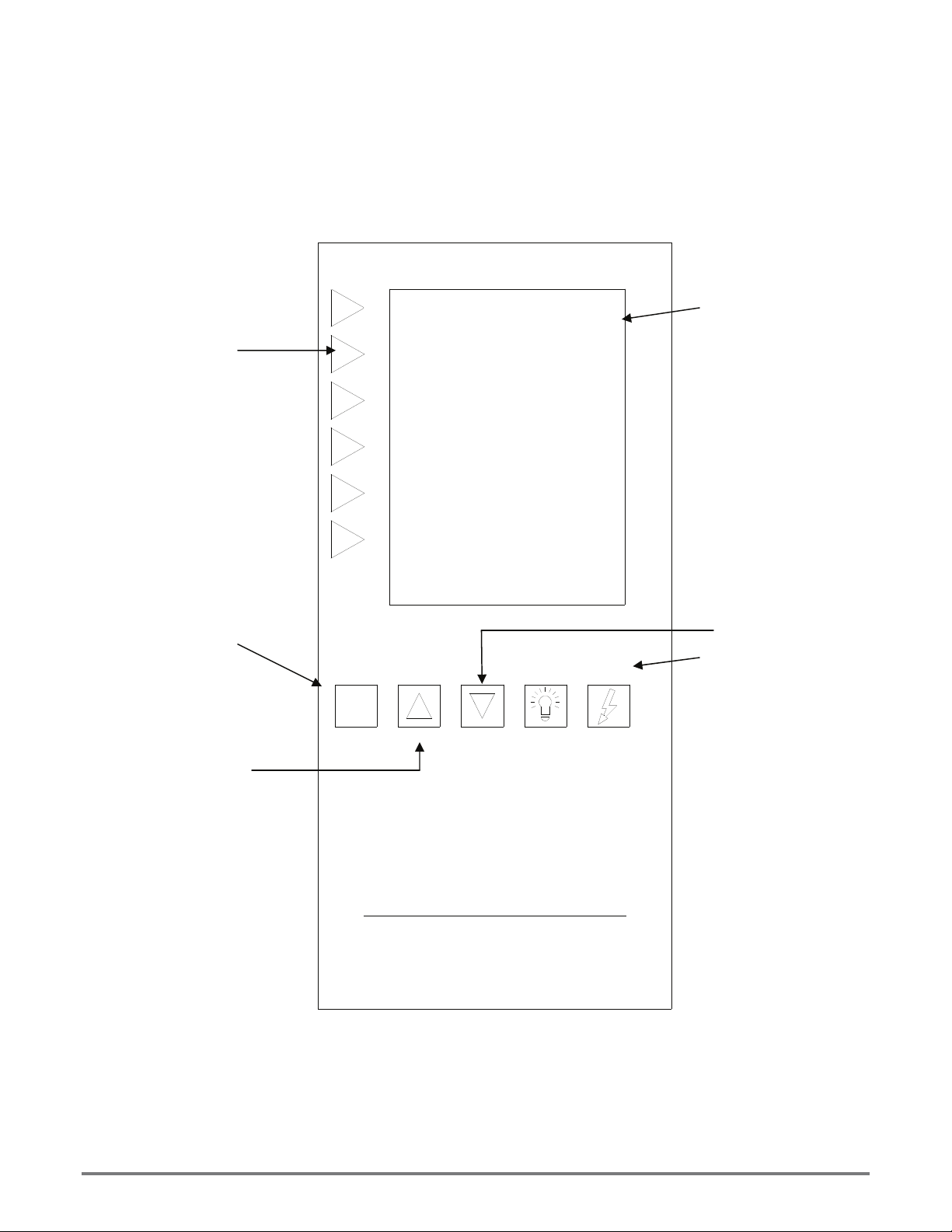
Oven
p
Function keys. Keys are
active when a program
option is displayed on
display.
Cancel button. When
scrolling through menu’s
this will allow you to back
up to the previous menu.
In program mode this will
allow you to advance to the
next ste
.
Initial Start Up cont'd.
Alpha-Numeric Display.
Arrow down button.
Allows you to scroll
down.
Arrow up button.
Allows you to scroll
up.
X
Cancel
P L A T I M U M
Up Down Light
Power switch.
On/Off
UL File# E8138 Rev New
12
Page 13
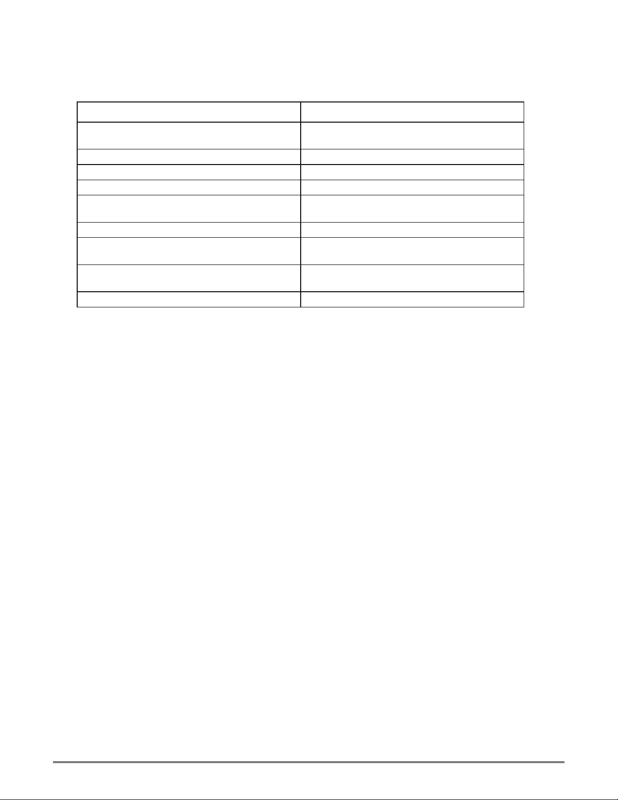
Typical Operation Sequence
Control Indicator
Press the On/Off switch.
Select "Run Oven". Products that can be baked are displayed
Select product button next to Icon desired. "Preheating to XXXF" is displayed
Beeper sounds briefly.
Select product to start.
Select product to start. "Select shelf" is displayed.
Press product button next to desired shelf.
Beeper sounds continuously.
Oven is ready for another product.
Hints & Suggestions
Convection ovens constantly circulate air over and around the product. This strips away the
thin layer of moisture and cool air from around the product allowing heat to penetrate more
quickly.
Cooking times will be shortened and cooking temperatures reduced.
To convert standard deck oven recipes, reduce the temperature 50 degrees a nd the time by
25%. Make minor adjustments as necessary.
Lowering the oven temperature will result in a more even bake.
Always weigh your product. This will give you a more consistent size, color and quality.
Check the product near the end of the initial cooking cycle.
Do not open the oven doors during baking as this will change the baking chara cteristics of
the oven and make it difficult to determine a final program.
If the product is overdone on the outside and underdone on the inside, reduce the baking
temperature.
If the product is pulling away from the edge of the pan, the temperature is too high or the
cooking time too long.
The convection is a mechanical piece of equipment. The same control settings will always
give the same results. If the results vary, problems may be because of product preparation.
Control panel comes on; "LANG, Run
Oven, Time Date Program is displayed
"Ready" is indicated
Product selection for that temperature is
displayed
Icon chosen will be displayed and the
countdown will begin
" DONE" is displayed, press button and
remove product from the shelf
Operation
Loading
When loading and unloading the oven, stage products and racks so the oven doors are
opened for the least amount of time.
Be sure that racks are level within the oven.
Bent or warped pans can greatly affect the evenness of the cook or bake.
If using baker’s parchment, be sure the parchment does not blow over the product. This may
create an uneven bake.
Load each shelf evenly. Spaces should be maintained equally between the pan and oven
walls, front and back.
Space pans evenly within the oven.
Do not overload pans. This may create an uneven bake.
UL File# E8138 Rev New
13
Page 14

Operation cont'd.
ALWAYS KEEP THE AREA NEAR THE APPLIANCE FREE FROM
COMBUSTIBLE MATERIALS AND DO NOT OBSTRUCT F LOW OF
CAUTION
RANGE TOP
Various top arrangements are available, depending on specific model purch ased:
12" x 24" hot plate, controlled by high temperature thermostats. Temperature ranges from 0°-850°F.
Recommended for stockpots and heavy kettle work.
Round French Plates, controlled by indicating type 6-heat switch. Temperature ranges from 0°-750°F.
Recommended for light duty sauce pans and small stockpots. Not Recommend ed for heavy stockpots, heavy
urns kettles.
18" x 24" grill plates, controlled by thermostats. Temperature ranges from 0°-450°F.
Recommended for all heavy and light frying. Set the thermostat dial at the desired
temperature. The red pilot light will be on until the desired temperature is reached. The pilot
light indicates when the plate is heating.
COMBUSTION OR VENTILATION AIR.
KEEP FLOOR IN FRONT OF EQUIPMENT CLEAN AND DRY. IF SPILLS
OCCUR, CLEAN IMMEDIATELY TO AVOID THE DANGER OF SLIPS OR
FALLS.
UL File# E8138 Rev New
14
Page 15
WARNING
CAUTION
NOTICE
Maintenance and Cleaning
KEEP WATER AND SOLUTIONS OUT OF CONTROLS. NEVER SPRAY OR
HOSE CONTROL CONSOLE, ELECTRICAL CONNECTIONS, ETC.
MOST CLEANERS ARE HARMFUL TO THE SKIN, EYES, MUCOUS
MEMBRANES AND CLOTHING. PRECAUTIONS SHOULD BE TAKEN TO
WEAR RUBBER GLOVES, GOGGLES OR FACE SHIELD AND
PROTECTIVE CLOTHING. CAREFULLY READ THE WARNING AND
FOLLOW THE DIRECTIONS ON THE LABEL OF THE CLEANER TO BE
USED.
Never leave a chlorine sanitizer in contact with stainless steel surfaces
longer than 10 minutes. Longer contact can cause corrosion.
Cleaning
• Always start with a cold range.
• The stainless exterior can easily be cleaned using a stainless steel cleaner.
• Always follow the cleaner manufacturer's instructions when using a ny
cleaner.
• Care should be taken to prevent caustic cleaning compounds from coming
in contact with the blower wheel.
• The oven racks, rack slides and interior may be cleaned using oven
cleaner.
• Discoloration or heat tint may be removed using carbon release oven
cleaner.
• Rub in the direction of the metal's grain.
UL File# E8138 Rev New
15
Page 16
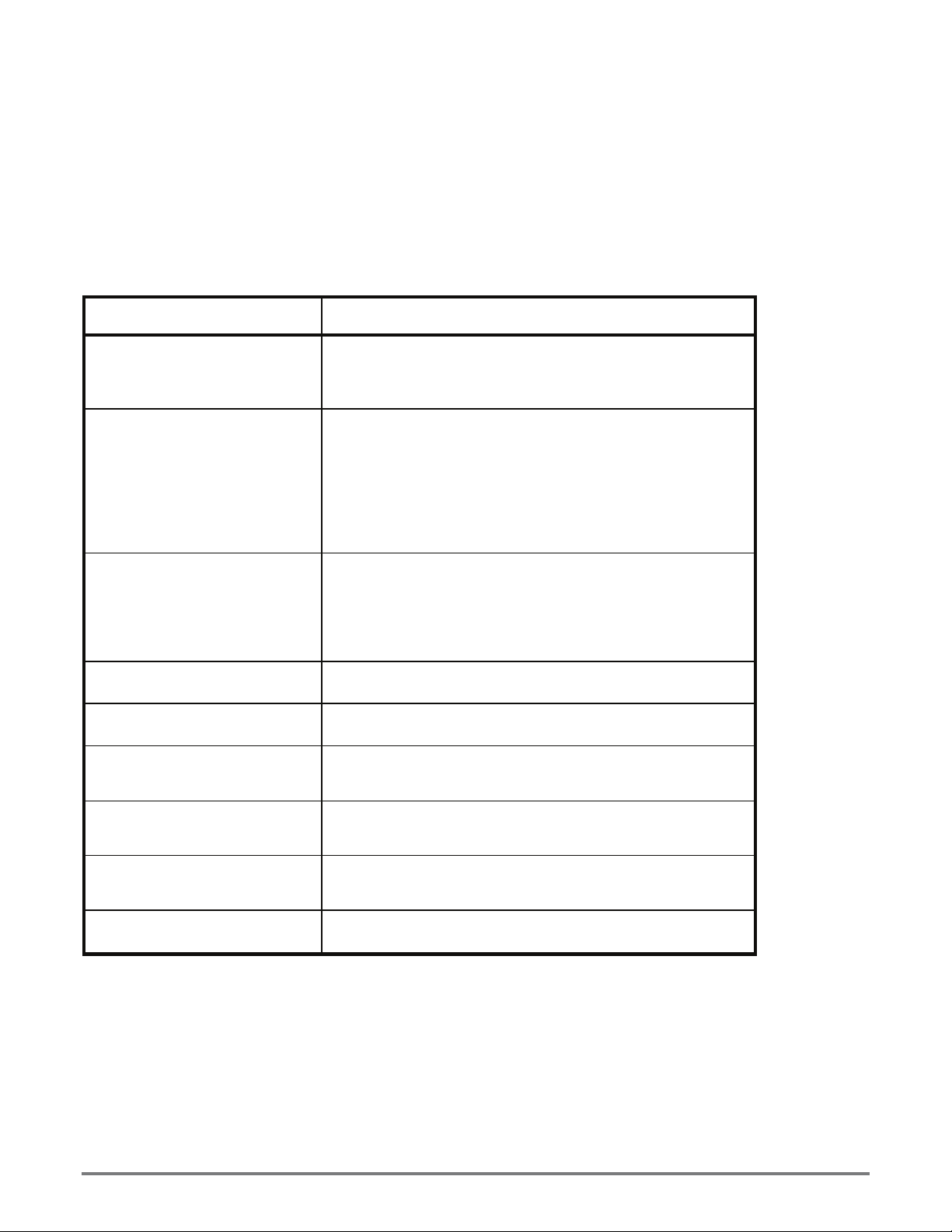
Troubleshooting
Symptoms
What follows is a chart of Symptoms and Possible Causes to aid in diagnosing faults with the appliance.
Refer to the Symptom column to locate the type of failure, then to the Possible Cause for the items to be
checked.
To test for a Possible Cause, refer to the Test section.
Oven
Symptom Possible Cause
No power to outlet
Display will not come on
Oven will not heat
Oven motor will not run
Product burning
Product under done
Hotplate will not heat
French plate will not heat
Griddle plate will not heat
Failed power cord or plug
Contrast needs to be adjusted
Failed display board
Power Switch is not “ON”
Product not selected
Failed Transformer
Failed Probe
Failed Circuit board
Failed Contactor
Failed Over-temperature Thermostat
Failed Element
Power Switch is not “ON”
Product not selected
Failed Transformer
Failed Contactor
Failed Motor
Failed Circuit board
Failed Probe
Failed Circuit board
Failed Probe
Failed Circuit board
No power to Unit
Defective Thermostat
Defective element
No power to Unit
Failed 6-heat switch
Failed element
No power to Unit
Failed Thermostat
Failed element
UL File# E8138 Rev New
16
Page 17
NOTICE
WARNING
Troubleshooting cont'd.
Service on this or any other Lang appliance must be performed by
qualified personnel only. Consult your Lang Authorized Service Agent
Directory. You can call our toll free number 1-800-807-9054 or visit our
website WWW.STAR-MFG.COM for the service agent nearest you.
BOTH HIGH AND LOW VOLTAGES ARE PRESENT INSIDE THIS
APPLIANCE WHEN THE UNIT IS PLUGGED/WIRED INTO A LIVE
RECEPTACLE. BEFORE REPLACING ANY PARTS, DISCONNECT THE
UNIT FROM THE ELECTRIC POWER SUPPLY.
TESTS
If an item on the list is followed by an asterisk (*), the work should be done
by a factory authorized service representative.
Oven
Possible Cause Test
Failed Probe Check probe for proper resistance*
Failed Circuit board
Failed Transformer
Failed Contactor
Failed Motor Confirm that motor is getting correct voltage*
Failed or disconnected safety
thermostat
Failed Element
Confirm that Circuit board is getting correct
voltage and putting out correct voltage*
Check both Primary and Secondary coils for
correct voltage*
Remove the wires from the contactor coil
and check for continuity across the contactor
coil connection*
Ensure the contactor moveable points move
freely up and down*
Check across the thermostat connectors for
continuity*
Confirm that Elements are getting correct
voltage and have continuity*
Range Top
Possible Cause Test
Failed thermostat Verify calibration*
Failed element
Failed 6-heat switch
USE OF ANY REPLACEMENT PARTS OTHER THAN THOSE SUPPLIED BY
CAUTION
STAR OR THEIR AUTHORIZED DISTRIBUTORS CAN CAUSE BODILY
INJURY TO THE OPERATOR AND DAMAGE TO THE EQUIPMENT AND
WILL VOID ALL WARRANTIES.
UL File# E8138 Rev New
Remove the wires and check for continuity
across the element*
Call factory or consult service manual for
proper tests
17
Page 18
Parts List June 18, 2010, Rev.A
RT30 RANGE TOP
Part No. Description Qty Application
R30DPTC208CF, R30CPTD208CF, R30CPTF208CF,
2B-50200-34 RACK HALF SIZE OVENS 5
2B-50200-83 RACK SLIDE EHS 2
2E-30301-02 SWT MICRO #2HLT-5 UNIMAX 1
2E-30303-06 SWT TOG ON-ON DPDT BLK 1
2E-30304-09 SWTROT 6 HEAT+OFF208/240V 2
2E-30500-07 TRM BLOCK 3PLELRGE 125AMP 1
2E-30500-08 TRM BLOCK 2 POLE SMALL 95 1
2E-30500-09 TRM BLOCK 3 POLE SMALL 95 1
2E-30503-01 TRM BLOCK 24 POS QK CON 1
2E-30600-02 RELAY 240VAC 3FORMC FLNG 1
2E-30700-06 CONTC3POLE35A24VAC50/60HZ 1
2E-30701-05 CONTC 2POLE 30A 24VAC P & 3
LUG GROUNDING UL
2E-31200-02
2E-31200-08 LUG GROUNDING TWO HOLE 1
2E-31400-04 XFRMR 480/240VAC 100VA 1 R30CPTG480CF
2E-31400-07 XFORMR120-208-240/24V40VA 1
2E-31400-26 XFORMR 208-240/24-12 40VA 1
2E-31800-01 CB 250V50A 1 POLE CRLNGSW 6
2E-31800-04 CB 480V 50A 3 POLE 1 R30CPTG480CF
2E-41100-12 SENSOR EHS OVEN 450 DEG 1
2J-31601-01 PILOT LT 250V 6LEAD BLK 1
2J-31601-01 PILOT LT 250V 6LEAD BLK 2
2J-31601-02 PILOT LT 480V 6LEAD BLK 1 RT30D-480VCF, RT30G-480VCF, R30CPTG480CF
2J-31601-02 PILOT LT 480V 6LEAD BLK 2 RT30F-480VCF
2J-40102-25 DSPLY 320X240 DB170-001 1
2J-40102-26 MAIN BOARD, MDL.CA170-001 1
2N-11010-34 HOTPLATE 208V 5000W CAST 4
APPROVED
R30CPTG208CF, R30CPTG480CF
R30DPTC208CF, R30CPTD208CF, R30CPTF208CF,
R30CPTG208CF, R30CPTG480CF
R30DPTC208CF, R30CPTD208CF, R30CPTF208CF,
R30CPTG208CF, R30CPTG480CF
R30DPTC208CF, R30CPTD208CF, R30CPTF208CF,
R30CPTG208CF, R30CPTG480CF
R30DPTC208CF, R30CPTD208CF, R30CPTF208CF, RT30G208VCF, R30CPTG208CF, RT30G-240VCF, RT30G-480VCF,
R30CPTG480CF
R30DPTC208CF, R30CPTD208CF, R30CPTF208CF,
R30CPTG208CF
RT30D-208VCF, R30CPTD208CF, RT30D-240VCF, RT30D480VCF, R30CPTD480CF, RT30F-208VCF, R30CPTF208 CF,
RT30G-208VCF, R30CPTG208CF, RT30G-240VCF, RT30G480VCF, R30CPTG480CF
R30DPTC208CF, R30CPTD208CF, R30CPTF208CF,
R30CPTG208CF, R30CPTG480CF
R30DPTC208CF, R30CPTD208CF, R30CPTF208CF,
R30CPTG208CF, R30CPTG480CF
R30DPTC208CF, R30CPTD208CF, R30CPTF208CF,
R30CPTG208CF, R30CPTG480CF
R30DPTC208CF, R30CPTD208CF, R30CPTF208CF,
R30CPTG208CF, R30CPTG480CF
R30DPTC208CF, R30CPTD208CF, R30CPTF208CF,
R30CPTG208CF, R30CPTG480CF
R30DPTC208CF, R30CPTD208CF, R30CPTF208CF,
R30CPTG208CF, R30CPTG480CF
1
R30DPTC208CF, R30CPTD208CF, R30CPTF208CF,
R30CPTG208CF, R30CPTG480CF
R30DPTC208CF, R30CPTD208CF, R30CPTF208CF,
R30CPTG208CF, R30CPTG480CF
R30DPTC208CF, R30CPTD208CF, R30CPTF208CF,
R30CPTG208CF, R30CPTG480CF
R30DPTC208CF, R30CPTD208CF, R30CPTF208CF,
R30CPTG208CF
R30DPTC208CF, R30CPTD208CF, R30CPTF208CF,
R30CPTG208CF, R30CPTG480CF
RT30D-208VCF, R30CPTD208CF, RT30D-240VCF,
R30CPT480CF, R30CPTF208CF, RT30G-208VCF,
R30CPTG208CF, RT30G-240VCF
RT30C-208VCF, RT30C-208VKR, R30DPTC208CF, RT30F208VCF
R30DPTC208CF, R30CPTD208CF, R30CPTF208CF,
R30CPTG208CF, R30CPTG480CF
R30DPTC208CF, R30CPTD208CF, R30CPTF208CF,
R30CPTG208CF, R30CPTG480CF
RT30C-208VCF, RT30C-208VKR, R30DPTC208CF,
R30CPT208CF, RT30D-240VCF, RT30D-480VCF
UL File# E8138 Rev New
18
Page 19
Parts List June 18, 2010, Rev.A
RT30D-208VCF, R30CPTD208CF, R30CPTD480CF, RT30F-
2N-11030-45 ELMNT GRID 18 RANGE 208V 1
2N-11030-46 ELMNT GRID 18 RANGE 240V 1 RT30D-240VCF, RT30G-240VCF
2N-11030-47 ELMNT GRID 18 RANGE 480V 1 RT30D-480VCF, RT30G-480VCF, R30CPTG480CF
2N-11030-55 ELE GRD 30 RNGE 208V5.5KW 2 RT30F-208VCF, R30CPT208CF
2N-11030-58 ELE GRD 30 RNGE 480V5.5KW 2 RT30F-480VCF
2N-11090-22 ELE EHS OVN 480VAC 7.5KW 1 R30CPT G480CF
2N-11090-23 ELMNT EHS OVEN 208VAC 5.0 1
2N-11090-23 ELMNT EHS OVEN 208VAC 5.0 1 R30CPTG208VCF
2N-11120-12 ELMNT TK 208V 2600W 2
2N-11120-13 ELMNT TK 240V 2600W 2 RT30D-240VCF, RT30G-240VCF
2N-11120-14 ELMNT TK 480V 2600W 2 RT30D-480VCF, RT30G-480VCF, R30CPTG480CF
2P-51001-12 SPRNGCOMPRSN.665IDX1.4LNG 3
2P-51001-19 SPRING SWT DR HINGE EHS 1
2P-51003-01 SPRING LEAF FOR EGO TK 2
2P-70201-01 BRNZBR.505IDX.8750DX.175 2
2P-70201-19 BRNZBRFLN1/2IDX5/8ODX3/8 2
2P-72900-04 CSTER RIGID 3,5/16W TRD. 2
2P-72901-17 CSTR SWVL W/BRK 35/16TRD 2
2Q-71301-04 WINDOW ASSY 9-5/8X16-5/8 1
2R-50800-12 DOOR T HANDLE 11 1/2 LNG 1
2R-70700-01 KNOB BLNK UNIVERSAL BLACK 2
2R-70700-01 KNOB BLNK UNIVERSAL BLACK 3
2R-70700-01 KNOB BLNK UNIVERSAL BLACK 4 RT30CPTD208CF, R30CPTG208CF, R30CPTG480CF
2R-70702-08 DIAL PLT 450° 72C/T 2 RT30F-480VCF
2R-70702-34 DIAL PLT 6-HEAT SWIT CH 2 RT30D-240VCF
2T-30401-09 STAT FXD 500 DEG OPEN 1
2T-30402-08 STAT ADJ 450o 72 C/T 1
2T-30402-08 STAT ADJ 450o 72 C/T 2 RT30F-208VCF
2T-30402-23 STAT ADJ 850o 48C/T NAK 2
2T-30402-27 STAT ADJ 450 DEG 48 PILOT 1
2U-30200-16 MTR 1/3HP 460V/1/60HZ 2SP 1 R30CPTG480CF
2U-30200-17 MTR 1/3HP208/240V1PH2SPD 1
208VCF, RT30G-208VCF, R30CPTG208CF
R30DPTC208CF, R30CPTD208CF, R30CPTF208CF,
R30CPTG208CF, R30CPTG480CF
RT30D-208VCF, R30CPTD208CF, R30CPTD480CF, RT30F208VCF, RT30G-208VCF, R30CPTG208CF
R30DPTC208CF, R30CPTD208CF, R30CPTF208CF,
R30CPTG208CF, R30CPTG480CF
R30DPTC208CF, R30CPTD208CF, R30CPTF208CF,
R30CPTG208CF, R30CPTG480CF
RT30D-208VCF, R30CPTD208CF, RT30D-240VCF, RT30D480VCF, R30CPTD480CF, RT30F-208VCF, R30PTF208CF,
R30CPTG208CF, R30CPTG480CF
R30DPTC208CF, R30CPTD208CF, R30CPTF208CF,
R30CPTG208CF, R30CPTG480CF
R30DPTC208CF, R30CPTD208CF, R30CPTF208CF,
R30CPTG208CF, R30CPTG480CF
R30DPTC208CF, R30CPTD208CF, R30CPTF208CF,
R30CPTG208CF, R30CPTG480CF
R30DPTC208CF, R30CPTD208CF, R30CPTF208CF,
R30CPTG208CF, R30CPTG480CF
R30DPTC208CF, R30CPTD208CF, R30CPTF208CF,
R30CPTG208CF, R30CPTG480CF
R30DPTC208CF, R30CPTD208CF, R30CPTF208CF,
R30CPTG208CF, R30CPTG480CF
RT30C-208VCF, RT30C-208VKR, RT30D-240VCF, RT30D480VCF, RT30F-480VCF
RT30D-208VCF, R30DPTC208CF, R30DPTC480CF, RT30F208VCF, R30PTF208CF, RT30G-208VCF, RT30G-240VCF,
RT30G-480VCF
R30DPTC208CF, R30CPTD208CF, R30CPTF208CF,
R30CPTG208CF, R30CPTG480CF
RT30D-208VCF, R30CPTD208CF, RT30D-240VCF, RT30D480VCF, R30CPTD480CF, R30CPTF208CF, RT30G-208VCF,
R30CPTG208CF, RT30G-240VCF, RT30G-480VCF,
R30CPTG480CF
RT30C-208VCF, RT30C-208VKR, RT30D-208VCF,
R30DPTC208CF, R30CPTD208CF, RT30D-240VCF, RT30D480VCF
R30DPTC208CF, R30CPTD208CF, R30CPTG208CF,
R30CPTG480CF
R30DPTC208CF, R30CPTD208CF, R30CPTF208CF,
R30CPTG208CF
UL File# E8138 Rev New
19
Page 20
Parts List June 18, 2010, Rev.A
R30DPTC208CF, R30CPTD208CF, R30CPTF208CF,
2U-30200-46 MTR W/FAN AXIAL 220VAC70C 1
2U-71500-06 BLOWER WHEEL EHS OVEN 1
N9-32-560-1 WRD TOP 208V 30GRID MOD 1 RT30F-208VCF, R30CPTF208CF
N9-32-332 3 INCH SPREADER-PLATE 2
N9-32-550 WRD TOP 208V 2 HOT TOP 1
P9-50300-82-2 EGOPLTE FRMEASY PHANT 32/ 1
P9-50300-83 EGO FRNCH HT PLTE FRME SS 1
P9-70701-38-1 KNOB 850o D PHANTOM 2
P9-70701-41 KNOB ASSY 6 HEAT EGOTK 2
P9-CR30-260 SPOT SMALL DRAWER 1
P9-CR30-850-1 WRD TOP 208V 2SPD&18TALL 1 RT30D-208V CF, R30CPTG208CF
P9-CR30-851-1 WRD TOP 240V 2SPD&18TALL 1 RT30D-240V CF, RT30G-240VCF
P9-CR30-852-1 WRD TOP 480V 2SPD&18TALL 1
Q9-EH-550 HRNSS EH-PP&PT PWER@ELE 1
Q9-EH-551 HARNESS EH-PP -PT HIGH V 1
Q9-EH-553 HARNESS EH-PP&PT LOW V 1
Q9-EH-554 HARNESS EH-PP POWER SW. 1
ECOH CONVECTION OVENS
Part No.
2B-50200-34 RACK HALF SIZE OVENS 5
2B-50200-83 RACK SLIDE EHS 2
2E-30301-02 SWT MICRO #2HLT-5 UNIMAX 1
2E-30303-06 SWT TOG ON-ON DPDT BLK 1
2E-30500-07 TRM BLOCK 3PLELRGE 125AMP 1 ECOHPT208CFR
2E-30500-09 TRM BLOCK 3 POLE SMALL 95 1
2E-30503-01 TRM BLOCK 24 POS QK CON 1
2E-30600-02 RELAY 240VAC 3FORMC FLNG 1
2E-30700-06 CONTC3POLE35A24VAC50/60HZ 1
2E-30701-05 CONTC 2POLE 30A 24VAC P & 3
2E-31200-02 LUG GROUNDING UL APPROVED 1
UL File# E8138 Rev New
R30CPTG208CF, R30CPTG480CF
R30DPTC208CF, R30CPTD208CF, R30CPTF208CF,
R30CPTG208CF, R30CPTG480CF
RT30C-208VCF, RT30C-208VKR, R30DPTC208CF,
R30CPT208CF, RT30D-240VCF, RT30D-480VCF
RT30C-208VCF, RT30C-208VKR, R30DPTC208CF,
R30CPT208CF, RT30D-240VCF, RT30D-480VCF
RT30D-208VCF, R30CPTD208CF, RT30D-240VCF, RT30D480VCF, R30CPTF208CF, RT30G-208VCF, R30CPTG208CF,
RT30G-240VCF, RT30G-480VCF, R30CPTG480CF
RT30D-208VCF, R30CPTD208CF, RT30D-240VCF, RT30D480VCF, R30CPTF208CF, RT30G-208VCF, R30CPTG208CF,
RT30G-240VCF, RT30G-480VCF, R30CPTG480CF
RT30C-208VCF, RT30C-208VKR, R30DPTC208CF,
R30CPT208CF, RT30D-240VCF, RT30D-480VCF,
R30CPTF208CF
RT30G-208VCF, R30CPTG208CF, RT30G-240VCF, RT30G480VCF, R30CPTG480CF
RT30C-208VCF, RT30C-208VKR, RT30D-208VCF,
R30DPTC208CF, R30CPTD208CF, RT30D-240VCF, RT30D480VCF, R30CPTF208CF, R30CPTG208CF, R30CPTG480CF
RT30D-480VCF, R30CPTD480CF, RT30G-480VCF,
R30CPTG480CF
R30DPTC208CF, R30CPTD208CF, R30CPTF208CF,
R30CPTG208CF, R30CPTG480CF
R30DPTC208CF, R30CPTD208CF, R30CPTF208CF,
R30CPTG208CF, R30CPTG480CF
R30DPTC208CF, R30CPTD208CF, R30CPTF208CF,
R30CPTG208CF, R30CPTG480CF
R30DPTC208CF, R30CPTD208CF, R30CPTF208CF,
R30CPTG208CF, R30CPTG480CF
Qty Application
ECOHPT208CFR, ECOHPT208CFC, ECOH-PT480CF, ECOHPT208CF
ECOHPT208CFR, ECOHPT208CFC, ECOH-PT480CF, ECOHPT208CF
ECOHPT208CFR, ECOHPT208CFC, ECOH-PT480CF, ECOHPT208CF
ECOHPT208CFR, ECOHPT208CFC, ECOH-PT480CF, ECOHPT208CF
ECOHPT208CFR, ECOHPT208CFC, ECOH-PT480CF, ECOHPT208CF
ECOHPT208CFR, ECOHPT208CFC, ECOH-PT480CF, ECOHPT208CF
ECOHPT208CFR, ECOHPT208CFC, ECOH-PT480CF, ECOHPT208CF
ECOHPT208CFR, ECOHPT208CFC, ECOH-PT480CF, ECOHPT208CF
ECOHPT208CFR, ECOHPT208CFC, ECOH-PT480CF, ECOHPT208CF
ECOHPT208CFR, ECOHPT208CFC, ECOH-PT480CF, ECOHPT208CF
20
Page 21

Parts List June 18, 2010, Rev.A
ECOHPT208CFR, ECOHPT208CFC, ECOH-PT480CF, ECOH-
2E-31200-08 LUG GROUNDING TWO HOLE 1
2E-31400-04 XFRMR 480/240VAC 100VA 1 ECOH-PT480CF
2E-31400-07 XFORMR120-208-240/24V40VA 1
2E-31400-26 XFORMR 208-240/24-12 40VA 1
2E-31800-01 CB 250V50A 1 POLE CRLNGSW 6 ECOHPT208CFR
2E-31800-04 CB 480V 50A 3 POLE 1 ECOH-PT480CF
2E-41100-12 SENSOR EHS OVEN 450 DEG 1
2E-41500-01 VARIST V47ZA1 OR V56ZA2 1
2E-41500-02 VARIST 230V DC MOV 1
2E-41800-02 PCB GUIDE 6675 6.675 LG 2
2E-60101-75 EHS CORD KIT BK/DENNY'S 1 ECOHPT208CFC, ECOH-PT208CF
2J-40102-25 DSPLY 320X240 DB170-001 1
2J-40102-26 MAIN BOARD, MDL.CA170-001 1
2J-40102-51 CIRBD FILTER 1
2J-40601-40 RES 270 OHM 1/2W 5% CF 1
2N-11090-22 ELE EHS OVN 480VAC 7.5KW 1 ECOH-PT480CF
2N-11090-23 ELMNT EHS OVEN 208VAC 5.0 1 ECOHPT208CFR, ECOHPT208CFC, ECOH-PT208CF
2P-51001-12 SPRNGCOMPRSN.665IDX1.4LNG 2
2P-51001-19 SPRING SWT DR HINGE EHS 1
2P-70201-01 BRNZBR.505IDX.8750DX.175 2
2P-70201-19 BRNZBRFLN1/2IDX5/8ODX3/8 2
2Q-71301-04 WINDOW ASSY 9-5/8X16-5/8 1
2R-50800-12 DOOR T HANDLE 11 1/2 LNG 1
2R-70700-01 KNOB BLNK UNIVERSAL BLACK 1
2T-30402-27 STAT ADJ 450 DEG 48 PILOT 1
2U-30200-16 MTR 1/3HP 460V/1/60HZ 2SP 1 ECOH-PT480CF
2U-30200-17 MTR 1/3HP208/240V1PH2SPD 1 ECOHPT208CFR, ECOHPT208CF C, ECOH-PT208CF
2U-30200-46 MTR W/FAN AXIAL 220VAC70C 1
PT208CF
ECOHPT208CFR, ECOHPT208CFC, ECOH-PT480CF, ECOHPT208CF
ECOHPT208CFR, ECOHPT208CFC, ECOH-PT480CF, ECOHPT208CF
ECOHPT208CFR, ECOHPT208CFC, ECOH-PT480CF, ECOHPT208CF
ECOHPT208CFR, ECOHPT208CFC, ECOH-PT480CF, ECOHPT208CF
ECOHPT208CFR, ECOHPT208CFC, ECOH-PT480CF, ECOHPT208CF
ECOHPT208CFR, ECOHPT208CFC, ECOH-PT480CF, ECOHPT208CF
ECOHPT208CFR, ECOHPT208CFC, ECOH-PT480CF, ECOHPT208CF
ECOHPT208CFR, ECOHPT208CFC, ECOH-PT480CF, ECOHPT208CF
ECOHPT208CFR, ECOHPT208CFC, ECOH-PT480CF, ECOHPT208CF
ECOHPT208CFR, ECOHPT208CFC, ECOH-PT480CF, ECOHPT208CF
ECOHPT208CFR, ECOHPT208CFC, ECOH-PT480CF, ECOHPT208CF
ECOHPT208CFR, ECOHPT208CFC, ECOH-PT480CF, ECOHPT208CF
ECOHPT208CFR, ECOHPT208CFC, ECOH-PT480CF, ECOHPT208CF
ECOHPT208CFR, ECOHPT208CFC, ECOH-PT480CF, ECOHPT208CF
ECOHPT208CFR, ECOHPT208CFC, ECOH-PT480CF, ECOHPT208CF
ECOHPT208CFR, ECOHPT208CFC, ECOH-PT480CF, ECOHPT208CF
ECOHPT208CFR, ECOHPT208CFC, ECOH-PT480CF, ECOHPT208CF
ECOHPT208CFR, ECOHPT208CFC, ECOH-PT480CF, ECOHPT208CF
ECOHPT208CFR, ECOHPT208CFC, ECOH-PT480CF, ECOHPT208CF
UL File# E8138 Rev New
21
Page 22
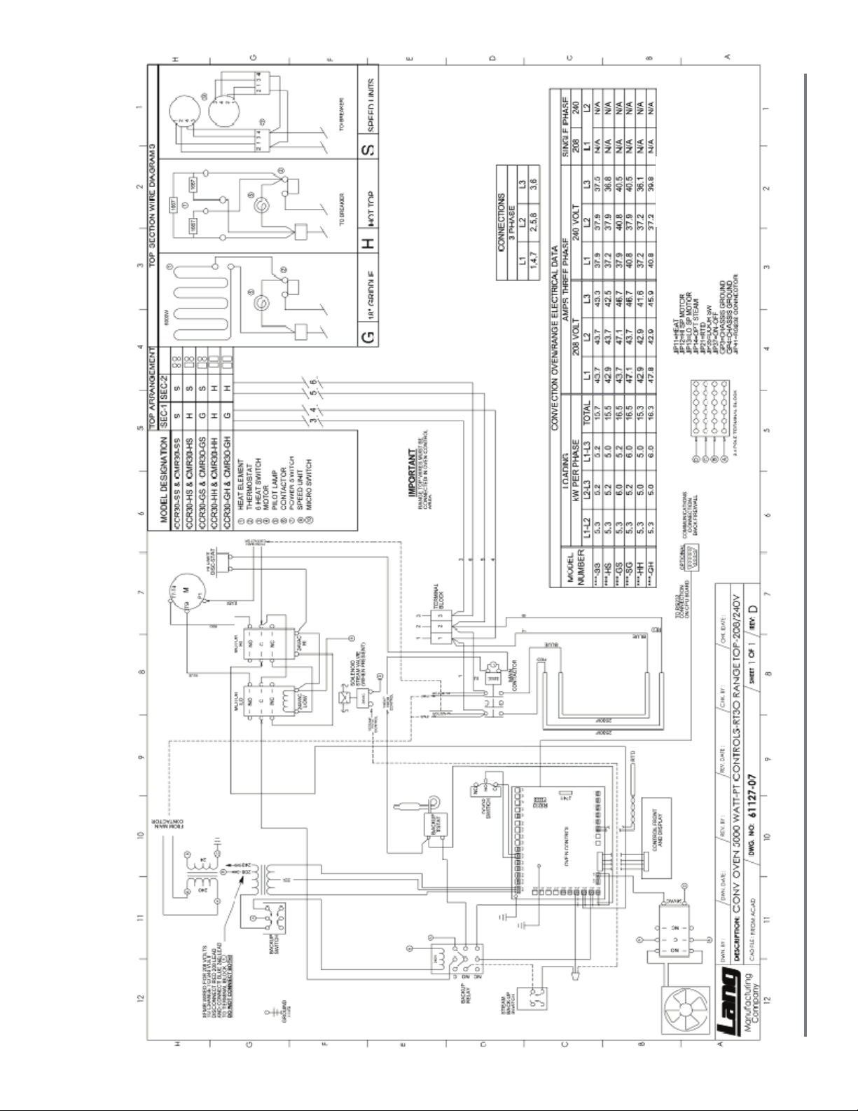
Wiring Diagram 208/240
22
UL File# E8138 Rev. New
Page 23
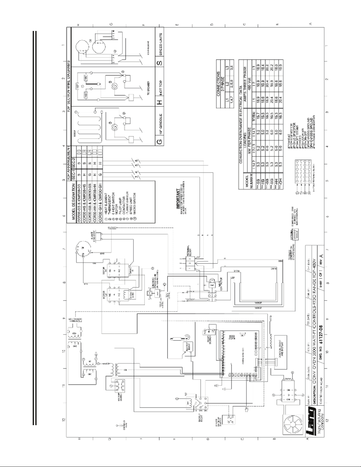
Wiring Diagram 480V
Page 24

STAR INTERNATIONAL HOLDINGS INC. COMPANY
Star - Holman - Lang - Wells - Bloomeld - Toastmaster
10 Sunnen Drive, St. Louis, MO 63143 U.S.A.
(800) 807-9054 (314) 781-2777
Parts & Service (800) 807-9054
www.star-mfg.com
 Loading...