

Page 1
ELECTRIC HALF SIZE
CONVECTION OVEN
ECOH-AP
RCOH-AP
Installation and
Operation
Instructions
2M-W491 Rev. G 3/24/15
ECOH-AP
IL1474
Page 2
SAFETY SYMBOL
These symbols are intended to alert the user to the presence of
important operating and maintenance instructions in the manual
accompanying the appliance.
DO NOT STORE OR USE GASOLINE OR OTHER FLAMMABLE VAPORS AND LIQUIDS IN
INSTRUCTIONS TO BE FOLLOWED IN THE EVENT USER SMELLS GAS. THIS
INFORMATION SHALL BE OBTAINED BY CONSULTING YOUR LOCAL GAS SUPPLIER.
AS A MINIMUM, TURN OFF THE GAS AND CALL YOUR GAS COMPANY AND YOUR
AUTHORIZED SERVICE AGENT. EVACUATE ALL PERSONNEL FROM THE AREA.
IMPROPER INSTALLATION, ADJUSTMENT, ALTERATION, SERVICE OR MAINTENANCE
CAN CAUSE PROPERTY DAMAGE, INJURY OR DEATH. READ THE INSTALLATION,
OPERATION & MAINTENANCE INSTRUCTIONS THOROUGHLY BEFORE INSTALLING OR
WARNING, TO REDUCE THE RISK OF ELECTRICAL SHOCK, DO NOT REMOVE
CONTROL PANEL. NO USER-SERVICABLE PARTS INSIDE.
REPAIRS SHOULD BE DONE BY AUTHORIZED SERVICE PERSONNEL ONLY.
FOR YOUR SAFTEY
THE VICINTIY OF THIS OR ANY OTHER APPLIANCE.
POST IN PROMINENT LOCATION
WARNING
SERVICING THIS EQUIPMENT.
WARNING
RISK OF FIRE OR ELECTRIC SHOCK
DO NOT OPEN
NOTICE
Using any part other than genuine Lang factory supplied parts relieves the manufacturer of all
liability.
Lang reserves the right to change specications and product design without notice. Such
revisions do not entitle the buyer to corresponding changes, improvements, additions or
replacements for previously purchased equipment.
Due to periodic changes in designs, methods, procedures, policies and regulations,
the specications contained in this sheet are subject to change without notice. While
Lang exercises good faith efforts to provide information that is accurate, we are not
responsible for errors or omissions in information provided or conclusions reached as a
result of using the specications. By using the information provided, the user assumes all risks
in connection with such use.
MAINTENANCE AND REPAIRS
Contact your local dealer for service or required maintenance. Please record the model number, serial
number, voltage and purchase & Installation Information in the area below and have it ready when you
call to ensure a faster service.
Model No.:
Serial No.:
Voltage:
Purchased From:
Location:
Purchase
Date:
1-Phase
or 3 Phase:
Installed Date:
Page 3

PROBLEMS, QUESTIONS or CONCERNS
Before you proceed consult you authorized Lang service agent directory
or
Call the Lang Technical Service & Parts Department at 314-678-6315.
TABLE OF CONTENTS
Specications . . . . . . . . . . . . . . . . . . . . . . . . . . . . . 4
Equipment Description . . . . . . . . . . . . . . . . . . . . . . . . 5
Unpacking . . . . . . . . . . . . . . . . . . . . . . . . . . . . . . . 6
Installation
Leg Installation . . . . . . . . . . . . . . . . . . . . . . . . . . 7
Stacking the Oven . . . . . . . . . . . . . . . . . . . . . . . . . 7
Ventilation & Clearance . . . . . . . . . . . . . . . . . . . . . . 8
Electrical Connection . . . . . . . . . . . . . . . . . . . . . . . 8
Oven Voltage . . . . . . . . . . . . . . . . . . . . . . . . . . . 8
Reversing the door . . . . . . . . . . . . . . . . . . . . . . . . . . 9
Initial Start-Up
Pre-Power On . . . . . . . . . . . . . . . . . . . . . . . . . . . 10
Power On . . . . . . . . . . . . . . . . . . . . . . . . . . . . . 10
General Operation & Programming
Control Panel . . . . . . . . . . . . . . . . . . . . . . . . . . .11
Typical Operation Sequence . . . . . . . . . . . . . . . . . . .11
Loading . . . . . . . . . . . . . . . . . . . . . . . . . . . . . .12
Maintenance
Cleaning . . . . . . . . . . . . . . . . . . . . . . . . . . . . . . 13
Troubleshooting
Symptoms & Possible Causes . . . . . . . . . . . . . . . . . .14
Wiring Diagram
208/240VAC, 7.8kW . . . . . . . . . . . . . . . . . . . . . . . . 15
480VAC, 7.8kW . . . . . . . . . . . . . . . . . . . . . . . . . . 16
220/380V & 240/415V . . . . . . . . . . . . . . . . . . . . . . . 17
2M-W491 Half Size Convection Oven, ECOH-AP
208/240V, 7500W for RT30 Range Top . . . . . . . . . . . . . . 18
208/240V 5.3kW, 2 Spd Mtr . . . . . . . . . . . . . . . . . . . . 19
Exploded View & Parts List . . . . . . . . . . . . . . . . . . . . . 20-28
NOTICE ServiceonthisoranyotherLangappliancemustbeperformedbyqualied
personnel only. Consult your Lang Authorized Service Agent Directory.
You can call our tech service dept. at 314-678-6315 or visit our website
www.langworld.com for the service agent nearest you.
3
Page 4
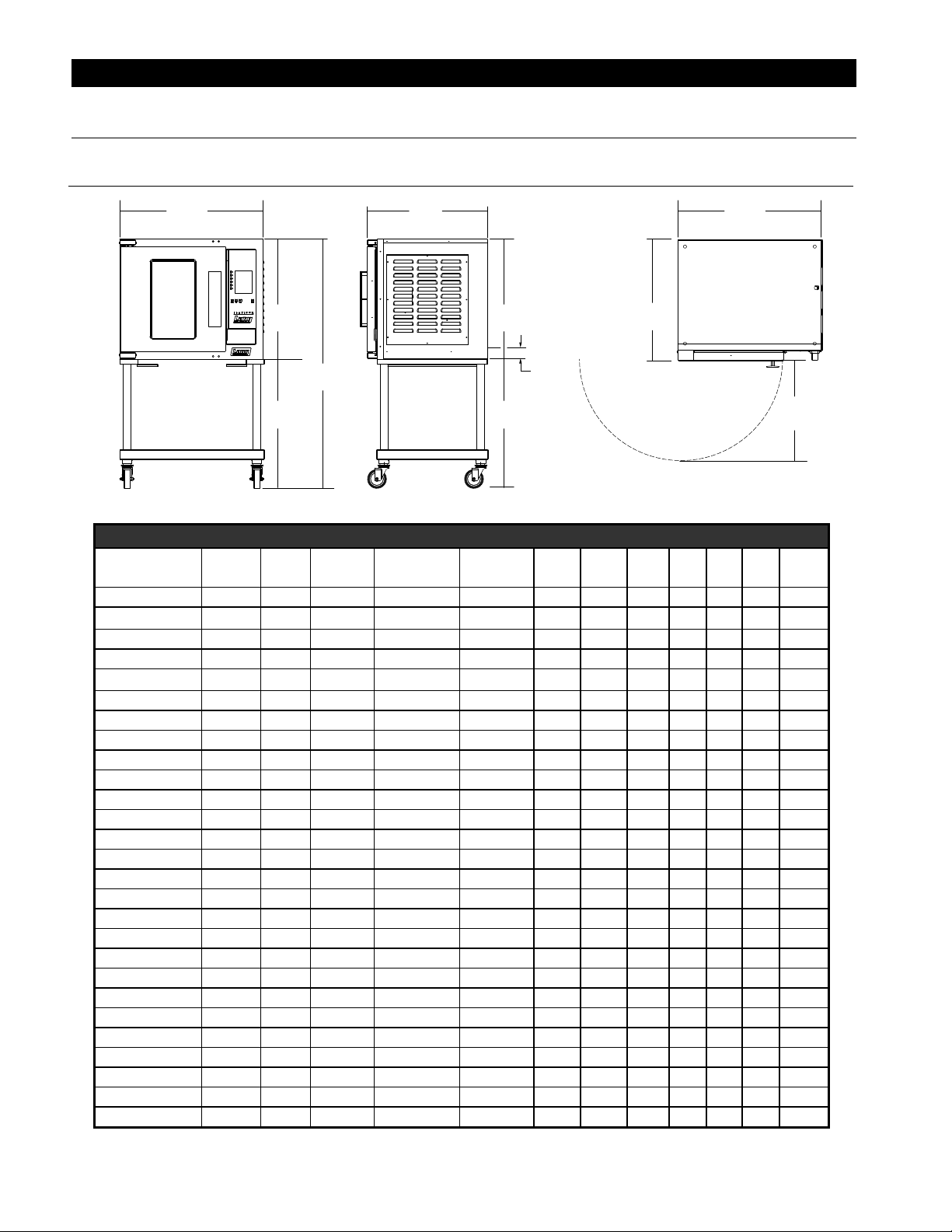
SPECIFICATIONS
30.2”
25.3”
30.2”
Model Height x Width x Depth Clearance from Weight
(without optional stand) combustible surface Installed Shipping Freight Class
ECOH/ 25.3” x 30.2” x 25.3” Side:6”, Back: 6”, Floor: 6” 185 lbs. 225lbs 85
RCOH 642mm x 766mm x 643mm (84 kg) (102 kg)
766mm
25.3”
642mm
53.3”
1353mm
28.0”
711mm
STAND OPTIONAL
Front Side View Top ViewRight Side View
643mm
25.3”
642mm
28.0”
711mm
3.0”
76mm
Electrical
Connection
25.3”
642mm
ELECTRICAL SPECIFICATIONS
Lang Number VOLTS AC Hz.
MOTOR
AMPS
PHASE
ECOH-AP-2/3 220/380 50/60 3.3 1/3PH-4WIRE 11 6.7 30 10 10 10 11 12
ECOH-AP2/3FA 220/380 50/60 3.3 1/3PH- 4WIRE 11 6.7 30 10 11 10 10 12
ECOH-AP208CF 208 60 3.3 1/3 5.3 25.5 10 25.5 25.5 10
ECOH-AP208DR 208 60 3.3 1/3 7.8 38 8 23 21 23 10
ECOH-AP208FA 220/380 50/60 3.3 1/3PH- 4WIRE 11 6.7 30 10 11 10 10 12
ECOH-AP-208M 208 60 3.3 1/3 7.8 38 8 23 21 23 10
ECOH-AP-208V 208 60 3.3 1/3 7.8 38 8 23 21 23 10
ECOH-AP240CF 240 60 3.3 1/3 5.3 22 10 22 22 - 10
ECOH-AP-240M 240 60 2.4 1/3 7.8 33 8 20 18 20 12
ECOH-AP240RS 240 60 2.6 1/3 7.8 33 8 20 18 20 12
ECOH-AP-240V 240 60 2.6 1/3 7.8 33 8 20 18 20 12
ECOH-AP-480M 480 60 1.0 3 7.8 10 9 10 12
ECOH-AP-480V 480 60 1.0 3 7.8 10 9 10 12
RCOHAP-2/3V 220/380 50/60 33 3 17 30 23 23 10
RCOHAP-208CF 208 60 3.3 3 5.3 25.5 10 25.5 25.5 - 10
RCOHAP-208KR 208 60 3.3 1/3 5.3 25.5 8 25.5 25.5 - 8
RCOHAP-208V 208 60 3 1/3 7.8 37.5 22 20.7 22 8
RCOHAP-240CF 240 60 2.6 1/3 5.3 22.1 22.1 22.1 - 10
RCOHAP-240V 240V 60 3.3 1/3 7.8 32.5 10 19.2 18.1 19.2 12
RCOHAP-240VM 240 60 3.3 1/3 7.8 32.5 10 32.5 32.5 RR
RCOHAP-440VM 440 60 1.4 3 6.6 8.8 8.3 8.8 12
RCOHAP-480CF 480 60 1.4 3 5.3 11 11 - 14
RCOHAP-480V 480 60 1.4 3 7.8 9.5 9 9.5 12
RCOHAP-480VM 480 60 1.4 3 7.8 9.5 9 9.5 12
RCOHRAP208KR 208 60 3.3 1/3 5.3 25.5 8 25.5 25.5 - 8
RCOHRAP-480M 480 60 33 3 8.1 9.7 9.7 9.7 12
RCOHRAP-480V 480 60 33 3 8.1 9.7 9.7 9.7 12
AMPS 3PH/
NEUTRAL
KW
TOT.
AMPS
1 PH
WIRE
1 PH
L1 L2 L3
766mm
IL1454
20.8”
529m
WIRE
3 PH
2M-W491 Half Size Convection Oven, ECOH-AP
4
Page 5
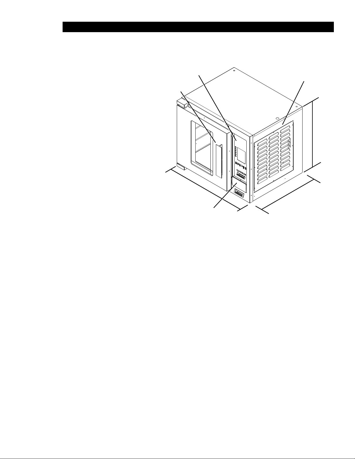
EQUIPMENT DESCRIPTION
Exterior Construction
The Top, Front, Back, and Sides are constructed of stainless steel with an aluminized bottom.
The oven exterior dimensions are:
30” (76.2 cm) Wide,
25.25” (74.3 cm) High,
26.5” (67.31 cm) Deep.
The oven door comes standard
with a high temperature insulated
window equipped with a
polycarbonate handle.
The oven cavity is insulated with high
temperature insulation for efciency
and reduced heat loss.
Interior Construction
The oven is designed for ve shelves
and comes with ve Chrome Plated
Racks.
The interior cooking chamber is
constructed of stainless steel with
dimensions of:
15” (38.1 cm) Wide,
20” (50.84 cm) High,
21” (53.38 cm) Deep.
Door Handle
Controls
Width
Depth
Back-Up Controls
Motor Cover
Height
IL1455
Operation
The ECOH oven is a forced air convection oven with a vented oven cavity.
The air is driven by a 1/3 HP fan motor.
Controls
Pre-Programmable Product Selections
Independent Shelf Timers for each Shelf.
Shelf Compensation Timing for uniform baking.
Technical
Oven operates as shipped on 208, or 240-volt (single or three phase), or 480-volt (three phase).
The oven can be shipped with a Power Cord and Plug attached, but must be specied upon ordering
(part number is listed in the Parts portion of this manual).
Floor space required is 42” (106.68cm) Wide, 32.5” (82.55cm) Deep.
The oven weighs approximately 225 lb. (102.5 Kilograms).
The ovens are stackable, stacking kit available upon request.
NOTICE
2M-W491 Half Size Convection Oven, ECOH-AP
The data plate is on the back side of the oven above the power cord.
The oven voltage, wattage, serial number, wire size, and clearance
specicationsareonthedataplate.Thisinformationshouldbecarefullyread
and understood before proceeding with the installation.
5
Page 6

CAUTION
UNPACKING
Receiving the Oven
Upon receipt, check for freight damage, both visible and concealed.
Visible damage should be noted on the freight bill at the time of delivery and
signed by the carrier’s agent. Concealed loss or damage means it does not
become apparent until the merchandise has been unpacked. If concealed
loss or damage is discovered upon unpacking, make a written request for
inspection by the carrier’s agent within 15 days of delivery. All packing material should be kept for inspection. Do not return damaged merchandise to
Star Manufacturing Company. File your claim with the carrier.
Location
Prior to un-crating, move the oven as near to its intended location as practical. The crating will help
protect the unit from the physical damage normally associated with moving it through hallways and
doorways.
Un-crating
The oven will arrive completely assembled inside a wood frame and strapped to a skid. Cut the
straps and remove the wood frame.
The oven can now be removed from the skid.
THE UNIT IS EXTREMELY HEAVY. FOR SAFE HANDLING, INSTALLER SHOULD
OBTAIN HELP AS NEEDED, OR EMPLOY APPROPRIATE MATERIALS
HANDLING EQUIPMENT (SUCH AS A FORKLIFT, DOLLY, OR PALLET JACK) TO
REMOVE THE UNIT FROM THE SKID AND MOVE IT TO THE PLACE OF
INSTALLATION.
ANY STAND, COUNTER OR OTHER DEVICE ON WHICH OVEN WILL BE
LOCATED MUST BE DESIGNED TO SUPPORT THE WEIGHT OF THE OVEN.
SHIPPING STRAPS ARE UNDER TENSION AND CAN SNAP BACK WHEN CUT.
2M-W491 Half Size Convection Oven, ECOH-AP
6
Page 7
Leg
Mounting Hole
4” Leg
INSTALLATION
16” or 28”
Stand
Cardboard
Leg Installation
4” legs are available for single
counter-top installations. Single
and double deck installations require 16” or 28” stand installation,
casters may also be used in certain
situations.
To install the 4” legs, place some
cardboard on the oor and gently tip
the unit onto its back. Fasten the
four, 4” legs into the threaded holes
located on the bottom of the unit.
Gently lift the oven into its operating
IL1430
position.
16” & 28” stand installation, after
following the assembly
instructions that were provided with
the stand, gently lower unit on to
some cardboard as shown here.
Align the stand with the bottom of
the unit and secure with the
hardware provided. With the
assistance of carefully raise the unit
to its vertical position.
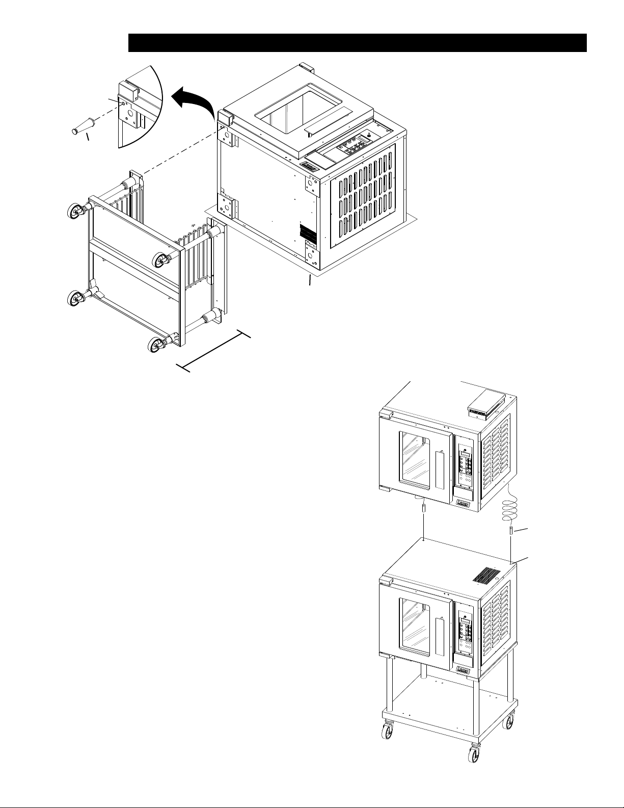
Stacking the Ovens
Two alignment pins (pn:2C-20108-11) are needed
if you intend on stacking two ECOH
on each other as shown. The stacking kit
9Q-ECOH-SK must be requested at the time of
purchase, or call your Lang authorized service
agent, or Lang parts department
at 314-678-6315.
Having completed the previous step remove any
and all button plugs from the lower unit, so the
upper unit will lay properly.
Lay the upper unit on its back and screw the
alignment pins into the two rear holes.
With assistance lift the upper unit onto the lower
unit, being certain that the alignment pins go into
the alignment holes, as shown here.
2M-W491 Half Size Convection Oven, ECOH-AP
NOTE: Each unit must have separate
electrical connections
Alignment Pins
pn: 2C-20108-11
Alignment Hole
IL1431
7
Page 8

INSTALLATION continued
Ventilation and Clearances
Standard minimum clearance from combustible construction is as follows.
4” from side
4” from back
6” from oor
• These ovens may be set directly, without legs, on a curbed base or non-combustible oor.
• If the oven is set without legs on a non-combustible oor or a curbed base, maintain a 4-inch back
clearance.
• If the oven is set directly against a non-combustible back wall, maintain a 6-inch clearance to the oor.
• Do not install the oven closer than 12 inches from an uncontrolled heat source (char broiler etc.) on
the right side.
• Keep the area free & clear of combustible material, and do not obstruct the ow of combustion or
ventilation air.
• The installation of any components such as a vent hood, grease extractors, and/or re extinguisher
systems, must conform to the applicable nationally recognized installation standards.
NOTICE The installation of any components such as a vent hood, grease
extractors,reextinguishersystems,mustconformtotheir
applicable National, State and locally recognized installation
standards.
WARNING
WARNING
Electrical Connection
The electrical connection must be made in accordance with local codes or in the absence of local codes
with NFPA No. 70 latest edition (in Canada use: CSA STD. C22.1).
The electrical service entrance is provided by a 1 1/4-inch knockout at the oven back directly behind the
control compartment. A grounding lug is provided at the rear service entrance.
Certain units are provided with or can be purchased with a Cord & Plug kit (Part number 9Q-ECOH-CK).
This kit includes a 48” cord with a NEMA L15-30P plug and is for 3 Phase units ONLY. In stacked situations each units needs to have separate cord & plug assemblies.
Oven Voltage
The Lang ECOH ovens can be operated on 208, 240-volt (single or three phase), or 480-volt (three
phase only) source. The Amp draw, KW rating, and phasing can be found in specication section of this
manual.
THIS APPLIANCE MUST BE GROUNDED AT THE TERMINAL PROVIDED. FAILURE
TO GROUND THE APPLIANCE COULD RESULT IN ELECTROCUTION AND DEATH.
INSTALLATION OF THE UNIT MUST BE DONE BY PERSONNEL QUALIFIED TO
WORK WITH ELECTRICITY AND PLUMBING. IMPROPER INSTALLATION CAN
CAUSE INJURY TO PERSONNEL AND/OR DAMAGE TO EQUIPMENT. UNIT MUST
BE INSTALLED IN ACCORDANCE WITH ALL APPLICABLE CODES.
2M-W491 Half Size Convection Oven, ECOH-AP
8
Page 9
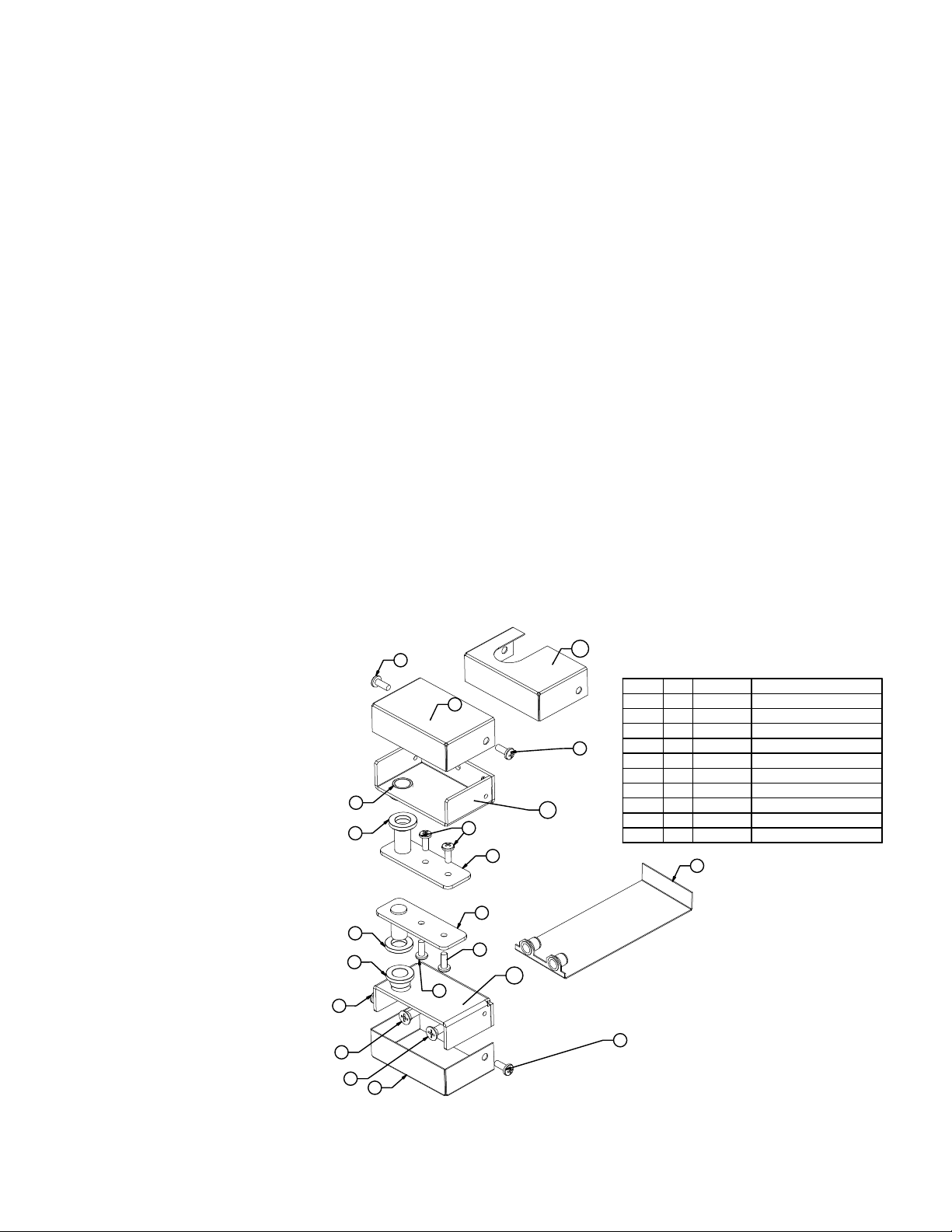
Reversing the door
1. Disconnect oven from power.
2. Remove the top and bottom door hinge covers (4) by removing the two 10-32 Phillip head
screws (8).
3. Remove the top door hinge bracket (1) from the oven by removing the two ¼-20 Phillip head
screws (7). The hinge should now slide off of the door pin (this will now be your right hand
lower hinge)
4. Lift the door off the bottom pin and set aside.
5. Remove the bottom door hinge bracket (2) by removing the two ¼-20 Phillip head screws (7)
(this will now be your upper right hand hinge).
6. Remove the lower hinge mounting plate (9) by pulling it from behind the leg pad adapter on the
bottom of the oven.
7. Remove the two Phillips head screws in the bottom right corner of the oven, where the new
hinge will be placed.
8. Slide the hinge mounting plate (9) into place and mount the hinge bracket (this should be your
old upper hinge) using two ¼-20 (7) Phillips head screws.
9. Remove the two Phillips head screws in the upper right corner of the oven where the new hinge
will be placed.
10. Rotate the door 180° and slide the door pin into the bottom hinge bracket.
11. Slide the upper door hinge (1) onto the upper door pin and then screw into place using
two ¼-20 Phillip head screws.
12. Place the top and bottom door hinge covers (4) back on the oven using two 10-32 Phillip head
screws (8).
2M-W491 Half Size Convection Oven, ECOH-AP
8
4
5
6
6
5
8
7
7
4
8
1
1
8
12
8
IL1426
10
11
ECOH HINGE RELPACEMENT KIT
pn: Q9-50313-030
ITEM NO. QTY. PART NO. DESCRIPTION
3
4
5
8
6
7
8
9
10
11
12
50313-031
2
EH-267
2
70201-19
2
70201-01
2
20109-43
2
20109-15
8
eh-198-1
1
CR30-148
1
EH-265-1
1
1 EH-266-1
9
INSERT BEARINGS (ITEMS "5") INTO THE HINGES
(ITEMS "1" & "2") AS SHOWN THEN REAM WITH A
.508 REAMER.
8
HINGE PIN WELDMENT
EH HINGE COVER
BOTTOM HINGE PLATE ASSY
UPPER HINGE COVER FOR EH
EH HINGE - TOP - FOR SVC KIT
EH HINGE - BOTTOM - FOR SVC KIT
9
Page 10
INITIAL START UP
Pre-Power On
After th oven is installed and connected to power, prior to turning on, verify the following
• The door opens and closes freely
• All racks are in the oven correctly
• All packing materials have been removed from the inside of the oven
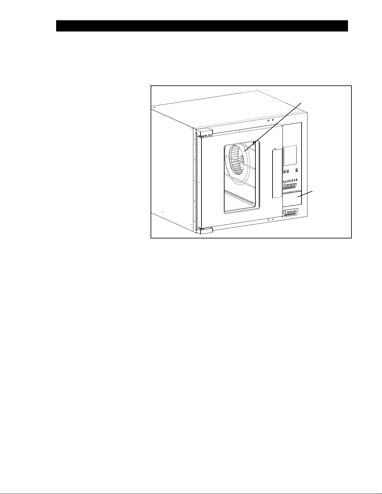
Power On
Once the oven has been turned
on verify that the blower wheel
is spinning freely in a clockwise
position and that the elements
are heating properly.
Switch the back-up controls on
and make certain it can run the
unit,
Conrm that the thermostat
knob in the back-up controls is
move freely.
Blower Wheel
NOTICE
AP units
Back-Up Controls
Conrm that all knobs move
freely and the timer beeps.
IL1456
Duringtherstfewhoursofoperationyoumaynoticeasmallamountofsmoke
coming from the oven, and a faint odor from the smoke.
Thisisnormalforanewunitandwilldisappearaftertherstfewhoursofuse.
10
2M-W491 Half Size Convection Oven, ECOH-AP
Page 11

General Operation & Programming
Convection ovens constantly circulate air over and around the product. This strips away the thin layer of moisture
and cool air from around the product allowing heat to penetrate more quickly.
Cooking times can be shortened and cooking temperatures can be reduced.
To convert standard deck oven recipes, reduce the temperature 50° degrees and the time by 25%. Make minor
adjustments as necessary.
Always weigh your product. This will give you a more consistent size, color and quality.
Check the product near the end of the initial cooking.
Do not open the oven door during baking, as this will change the baking characteristics of the oven and make it
difcult to determine a nal program.
If the product is overdone on the outside and underdone on the inside, reduce the baking temperature.
If the product is pulling away from the edge of the pan, the temperature is too high or the cooking time too long.
A convection oven is a mechanical piece of equipment. The same control settings will always give the
same results.
If the results vary, problems may be because of
changes in the product preparation.
ECOH-AP Control Panel
The Control panel consists of the following items.
Detailed operational descriptions are given later this
section.
Power Switch: Turns the oven on and off
Pulse Fan Switch:
Pulse Setting: Fan will only turn ON, when the
oven is calling for heat.
Fan Setting: Fan is on continuously, speed is
determined by the Hi/Low switch.
Hi/Low Speed Fan Switch: Dual speed switch.
Toggles the fan between high & low speed.
Temperature Control: Allows temperature to be set
in 25°F increments from 140°F to 450°F
Timer: Electronic on-hour timer with
continuous beeper,
Power Switch
Pulse Fan Switch &
Hi/Low Speed Switch
Heat Call Light
Temperature
Control
Typical Operation Sequence
Action Result
Turn Power Switch to ON
Adjust temperature, between
140°F & 450°F and allow 20
minutes for preheating
2M-W491 Half Size Convection Oven, ECOH-AP
Open oven door and insert
product, set timer up to 60
minutes.
Timer beeps continuously
when done.
Control panel heat call
light comes on.
Oven begins heating
Timer begins counting
down.
Product should now be
done.
Timer
IL1457
11
Page 12

General Operation & Programming cont.
Loading
Here are some things to remember when loading your oven.
• When loading and unloading the oven, stage products and racks so the oven door is opened for the least amount
of time.
• Be sure that racks are level within the oven.
• Bent or warped pans can greatly affect the evenness of the cook or bake.
• If using baker’s parchment, be sure the parchment does not blow over the product. That will create an uneven
bake.
• Load each shelf evenly. Spaces should be maintained equally between the pan and oven walls, front and back.
• Do not overload pan’s this will create an uneven bake.
• For best baking results, load the oven from the center out during random loading.
ALWAYS KEEP THE AREA NEAR THE APPLIANCE FREE FROM
COMBUSTIBLE MATERIALS.
CAUTION
KEEP FLOOR IN FRONT OF EQUIPMENT CLEAN AND DRY. IF SPILLS OCCUR,
CLEAN IMMEDIATELY, TO AVOID THE DANGER OF SLIPS OR FALLS.
12
2M-W491 Half Size Convection Oven, ECOH-AP
Page 13

MAINTENANCE
• Oven interiors should be wiped down daily and thoroughly cleaned weekly using warm water and mild detergent.
DO NOT use caustic cleaners.
• The appliance should be thoroughly checked at six-monthly intervals by a qualied
technician (heating unit, mechanical stability, corrosion...) with particular emphasis on all control and safety
devices.
CLEANING
• Always start with a cold oven.
• The stainless exterior can easily be cleaned using stainless steel cleaner.
• Always follow the cleaner manufacturer’s instructions when using any cleaner.
• Care should be taken to prevent caustic cleaning compounds from coming in contact with the fan wheel.
• The oven racks, rack slides, may be cleaned outside the oven cavity using oven cleaner.
• Using any harsh chemicals will result in the removal of the ETC coating and etching of the
porcelain below it. The oven interior should only be cleaned using a mild soap and a non metal scouring pad.
DO NOT use caustic cleaners.
• Always apply stainless steel cleaners when the oven is cold and rub in the direction of the metal’s grain.
KEEP WATER AND SOLUTIONS OUT OF CONTROLS. NEVER SPRAY OR HOSE
CONTROL CONSOLE, ELECTRICAL CONNECTIONS, ETC.
WARNING
MOST CLEANERS ARE HARMFUL TO THE SKIN, EYES, MUCOUS
MEMBRANES AND CLOTHING. PRECAUTIONS SHOULD BE TAKEN TO WEAR
CAUTION
RUBBER GLOVES, GOGGLES OR FACE SHIELD AND PROTECTIVE
CLOTHING.
CAREFULLY READ THE WARNING AND FOLLOW THE DIRECTIONS ON THE
LABEL OF THE CLEANER TO BE USED.
NEVER LEAVE A CHLORINE SANITIZER IN CONTACT WITH STAINLESS STEEL
SURFACES LONGER THAN 10 MINUTES. LONGER CONTACT CAN CAUSE
CORROSION.
2M-W491 Half Size Convection Oven, ECOH-AP
13
Page 14

Troubleshooting
Symptoms & Possible Causes
The following are charts of Symptoms and Possible Causes to aid in diagnosing faults with your unit.
Refer to the symptoms column to locate the type of failure then to the Possible Cause for the items to be checked.
To test for a possible cause refer to test to identify test procedures. Test indicated with an “*” should be done by a
Lang factory authorized service representative.
Symptoms Possible Cause
No power to cord outlet
Power indicator is
not lit
Oven will not heat
Oven motor will not
run
Product burning
Product is under
done
Oven unplugged from outlet
Failed Power cord or plug
Failed power switch
Failed indicator light
Power Switch is not “ON”
Failed Transformer
Failed Probe
Failed Circuit board
Failed Contactor
Failed Over-temperature Thermostat
Failed Element
Power Switch is not “ON”
Failed Transformer
Failed Contactor
Failed Motor
Product is cooked too long
Failed Probe
Failed Circuit board
Product is not cooked long enough
Failed Probe
Failed Circuit board
Possible Cause Test
Product is cooked too
long
Failed Probe Check probe for proper resistance*
Failed Circuit board
Failed Transformer
Failed Contactor
Failed Motor
Failed or disconnected
safety thermostat
Failed Element
No test available, operational
condition
Conrm that Circuit board is getting
correct voltage and putting out
correct voltage*
Check both Primary and Secondary
coils for correct voltage*
Remove the wires from the
contactor coil and check for
continuity across the contactor coil
connection*
Ensure the contactor movable
points move freely up and down*
Conrm that motor is getting correct
voltage*
Check across the thermostat
connectors for continuity*
Conrm that Elements are getting
correct voltage and have continuity*
NOTICE If an item on the list is followed by an asterisk (*), the work should be done by
a Lang factory authorized service representative.
USE OF ANY REPLACEMENT PARTS OTHER THAN THOSE SUPPLIED BY
LANG OR THEIR AUTHORIZED DISTRIBUTORS CAN CAUSE BODILY INJURY
CAUTION
TO THE OPERATOR AND DAMAGE TO THE EQUIPMENT AND WILL VOID ALL
WARRANTIES.
NOTICE ServiceonthisoranyotherLangappliancemustbeperformedbyqualied
personnel only. Consult your Lang Authorized Service Agent Directory. You
can call tech service department 314-678-6315 or visit our website
www.langworld.com for the service agent nearest you.
BOTH HIGH AND LOW VOLTAGES ARE PRESENT INSIDE THIS APPLIANCE
WHEN THE UNIT IS PLUGGED/WIRED INTO A LIVE RECEPTACLE. BEFORE
WARNING
REPLACING ANY PARTS, DISCONNECT THE UNIT FROM THE ELECTRIC
POWER SUPPLY.
14
2M-W491 Half Size Convection Oven, ECOH-AP
Page 15

-AP
D
D
KW AMPS
VOLTS
L1-L2 L2-L3 L3-L1 TOTAL L1 L2 L3 1 PH
37.5
22.1
20.8
22.1
7.8
2.8
2.5
2.5
208
ECOH
POWER
SWITCH
32.5
19.1
18.0
19.1
7.8
2.8
2.5
2.5
240
ECOH
2-4-61-3-5
L1 L2
SINGLE PHASE
L2 L3
2-5 3-6
SERVICE CONNECTIONS
THREE PHASE
L1
1-4
GROUND LUG
B
208
240
BCD
24
TERMINAL BLOCK
12 POLE
C D
BLUE
LO
SWITCH
2-SPEED
C
HIGH
5/22/2009
RED
T7-T4
M
T9
P1
BLACK
2M-61111-135 Rev D
C
NC C NO
24VAC
D
TO POWER SWITCH
TO CHANGE TO 240V
XFMR WIRED FOR 208V
TIMER
C
2M-W491 Half Size Convection Oven, ECOH-AP
DO NOT CONNECT BOTH
CONNECT ORANGE 240 LEAD
DISCONNECT RED 208 LEAD &
BUZZER
10
D
C
HEAT
24VAC
HEAT LIGHT
D
6
7
8
9
-AP
1
543
2
12
SWITCH
POSITION
345
CONTROL
"HEAT"
FROM
LIGHT
PULSE MODE
1
2
NCC
B
NO
DOOR SWITCH
ON
TOP
24VAC
RTD
C
PULSE
1
2
3
D
6
MOTOR
CONTACTOR #1
MOTOR
24VAC
14523
TERMINAL BLOCK
24VAC
C
HIGH LIMIT
DISC STAT
D
C
CONTACTOR #2
MODELS:
ECOH-AP, RCOH-AP 208/240VAC
EHS-AP, 208/240VAC
CONTROL
15
2500W
2500W
2500W
NO REPRODUCTION OR DISCLOSURE OF ITS CONTENTS IS PERMITTED.
THIS DRAWING CONTAINS INFORMATION CONFIDENTIAL TO STAR MFG. INT'L. INC.
2 5 4 3 6 1
Page 16

05/22/09
04/13/09
01/17/08
JMM
DJS
DJS
REVISION BLOCK
DELETED WIRE LABEL SHEET
ADDED CONTACTOR #2, REVISE
WIRING @ MOTOR RELAY &
BUZZER TO MATCH PRODUCTION
WIRE TO DOOR SWITCH NC WAS NO
B 6485
C 7878
7977
D
ECN NO.REV DESCRIPTION DR: DATEMFG ENG
KW AMPS
VOLTS
DRAWING NUMBER REV
480VAC
.X ± .05
.XX ± .03
TOLERANCES
ANGLES
± 1/64
FRACTIONS DECIMALS
SHEET
1 1
NEXT HIGHER ASSY.
.XXX ± .015
± .5°
UNLESS OTHERWISE SPECIFIED
DIMENSIONS ARE IN INCHES
2M-61111-163 D
OF
TO FIT
SCALE:
SWITCH
2-SPEED
LO
HIGH
GROUND LUG
RED
TERMINAL BLOCK
12 POLE
BLUE
BCD
L1-L2 L2-L3 L3-L1 TOTAL L1 L2 L3
480 2.5 2.5 2.8 7.8 9.5 9.0 9.5
ECOH
B
C
T7-T4
M
T9
P1
BLACK
C
NC C NO
24VAC
CREATED BY STUART R. CARTIER
W/D EH-AP
TITLE:
LANG MANUFACTURING
9-9-98
PART NUMBERQTY ITEM DESCRIPTION / MATERIAL
DATE:
TPV
DR:
DATE:
TPV
CK:
-AP
CONTROL
C
POWER
SWITCH
TIMER
BUZZER
D
480
C
HEAT
24VAC
HEAT LIGHT
D
9
10
-AP
543
2
12
SWITCH
POSITION
24
C D
NCC
B
NO
DOOR SWITCH
CONTROL
"HEAT"
FROM
ON
TOP
PULSE MODE
LIGHT
24VAC
1
2345678
1
RTD
C
PULSE
1
2
3
D
MOTOR
CONTACTOR #1
MOTOR
24VAC
14523
6
TERMINAL BLOCK
HIGH LIMIT
DISC STAT
D
C
24VAC
CONTACTOR #2
C
16
2500W
2500W
2M-W491 Half Size Convection Oven, ECOH-AP
2500W
2 5 4 3 6 1
Page 17

2-SPEED
SWITCH
LO
HIGH
DR
DJS
DJS
RED
GROUND LUG
TO MATCH PRODUCTION
REVISIONS
DESCRIPTION OF CHANGE
ADDED CONTACTOR #2, REVISED
MADE WIRE LABEL SEPERATE FILE
WIRING AT MOTOR RELAY, AND TIMER
4/2/2009
5/22/2009
ECO 7878
ECO 7977
E
D
REV. DATE/ECO
B
PRIMARY
FROM
7
24VAC
HEAT LIGHT
D
6
-AP
5
CONTACTOR #1
4
3
TIMER
D
BUZZER
POWER
SWITCH
10
C
HEAT
8
9
D
1
543
2
12
SWITCH
POSITION
2M-W491 Half Size Convection Oven, ECOH-AP
-AP
CONTROL
B
24
FROM
"HEAT"
CONTROL
PULSE MODE
LIGHT
24VAC
1
2
BLUE
12 POLE
TERMINAL BLOCK
D
C
D
C D
NCC
NO
ON
TOP
C
PULSE
D
MOTOR
1
T7-T4
M
T9
P1
BLACK
D
NC C NO
24VAC
HIGH LIMIT
DISC STAT
D
1
N
SINGLE PHASE
TERMINAL BLOCK
3
4
5
6
1
2
1
2
3
N
3 PHASE
4
2
MOTOR
3
6
6
TERMINAL BLOCK
1
5
3
E
REV:
1
OF
1
SHEET
2M-61111-167
#1
CONTACTOR
RTD
24VAC
D
#2
24VAC
CONTACTOR
DWG. NO:
C
W/D EH-AP 220/380 & 240/415
DLG
FROM ACAD
CAD FILE :
DESCRIPTION:
DWN. BY :
17
2 5 4 3 6 1
Page 18

1
H
2
G
F
E
D
C
B
A
421
5
5
2 1 3 4
3
2 1 3 4
1
TO BREAKER
2
2
TO BREAKER
2
3
SEE SHEET 2 FOR INDUCTION
4
LUG
GROUND
9
3
124
3
1667
1
1667
3
1667
1
6000W
4
5 6
PILOT LAMP
CONTACTOR
POWER SWITCH
7
6
5
NC
C
NO
NC
DOOR
SWITCH
BUZZER
3 4
SPEED UNIT
MICRO SWITCH
9
10
24VAC
C
HEAT
IMPORTANT
RANGE TOP WIRES MUST BE
CONNECTED IN OVEN CONTROL AREA.
24V
HEAT LIGHT
ON
TOP
C
D
SINGLE PHASE
THREE PHASE
PULSE
PULSE MODE
LIGHT 24 VAC
POWER
L2
L1
L3
L2
L1
SWITCH
TERMINAL
BLOCK
3
2
11
TERMINAL
BLOCK
3
2
5
D
C
B
12 POLE TERMINAL BLOCK
2
4
6
5
3
1
6
3
5
2
4
1
MOTOR
MOTOR
6
5
4
3
2
1
24VAC
6
BR6
BR5
BR4
BR3
BR2
BR1
#1
CONTACTOR
D
REV:
2
OF
1
SHEET
6
7
8
5
4
3
D
HI LIMIT
BLUE
WHITE
RED
DISC-STAT
24VAC
#2
CONTACTOR
C
RED
WHITE
BLUE
2.5 KW
2.5 KW
2.5 KW
CHK. DATE :
CHK. BY :
9
REV. DATE :
B
D
24
208
240
C
REV. BY :
2M-61127-11
10
DWG. NO:
2M-W491 Half Size Convection Oven, ECOH-AP
5
HEAT ELEMENT
THERMOSTAT
6 HEAT SWITCH
BLACK
MOTOR
4
3
1
2
C
NO
6
SWITCH
2-SPEED
LO
7
8
9
DR
JMM
10
HIGH
P1
BLUE
T9
M
RED
T7-T4
D
DJS
JMM
11
TO MATCH PRODUCTION
REVISIONS
DESCRIPTION OF CHANGE
ADDED SHEET 2: INDUCTION TOP
ADDED CONTACTOR #2, REVISED
UPDATED MODEL DESIG. TO STAR.
WIRE TO DOOR SWITCH NC WAS NO;
WIRING @ MOTOR RELAY AND TIMER
-AP
12
5/7/2009
1/17/2008
DATE/ECO
B
REV.
H
ECO 7946
C
3/20/12
ECO 11482
D
CONTROL
G
TIMER
TO POWER SWITCH
E
TO CHANGE TO 240V
DO NOT CONNECT BOTH
XFORMER WIRED FOR 208V
CONNECT ORANGE 240 LEAD
DISCONNECT RED 208 LEAD &
RTD
DWN. DATE :
CONV OVEN 7500 WATT-AP CONTROLS-RT3O RANGE TOP-208/240V
11
FROM ACAD
CAD FILE :
DESCRIPTION:
DWN. BY :
12
Company
D
C
B
Manufacturing
A
D
1
2
SWITCH
123456789
10
-AP
543
12
POSITION
F
18
Page 19

WD for: ECOH-AP208CF, ECOH-AP240CF
2M-W491 Half Size Convection Oven, ECOH-AP
19
Page 20

1
31
30
See
Door Assembly
Panel Assembly
29
25
26
See
28
27
24
23
22
See Body Assembly
2
19
20
21
18
17
16
3
4
See
8
Controller
Assembly
5
6
7
10
9
11
12
ECOH Complete Assembly
13
14
15
SK2320 Rev. B 6/1/2009
Page 21

PARTS LIST March 24, 2015, Rev G
Model No: ECOH & RCOH, AP, PP & PT CONTROLS
Commercial & Marine Half Size Economy Convection Oven
Fig No PART NO Qty DESCRIPTION Application
2N-11090-20
2N-11090-21 ELMNT EHS 240V 7.5KW
1
2N-11090-22 ELMNT EHS OVEN 480VAC 7.5KW 440VM, 480V, 480VM
2N-11090-23 ELMNT EHS OVEN 208VAC 5.0 KW RCOHAP-208KR, RCOHRAP208KR, RCOHPT-208CF, RCOH-AP-208CF
2N-11090-24 ELMNT EHS OVEN 240VAC 5.0 ECOH-AP240CF, RCOHAP-240CF, RCOHPT-240CF
2E-30500-15
2E-30500-07 TRM BLOCK 3PLELRGE 125AMP ECOHPT208CFR, RCOHPT-208CF, RCOHPT-240CF, RCOHAP-208CF
2
2E-30500-09 TRM BLOCK 3 POLE SMALL 95
3 2E-30700-06 1 CONTC3POLE35A, 24VAC
4 2C-20102-08 2 SCRW PHD ST 8-32X.375
Q9-60101-767
Q9-EHPAP-GFA PANEL EH 220/380V ACCU-PLUS FA ECOH-AP208FA, ECOH-AP2/3FA
Q9-EHPAPRT-C PANEL EH 208/240V AP W/RT30 RCOHAP-208KR, RCOHAP-208V, RCOHRAP208KR
Q9-EHPAP-U PANEL EH 480 VOLT ACCU-PLUS ECOH-AP-480M, 480V, RCOHAP-480V, 480VM, RCOHRAP-480M, 480V
Q9-EHPPP-C
5
Q9-EHPPP-C-W1 PANEL EH 208/240V PP ECOH-PP-208V, 208BK, 208WB, 240BK, 240WB, (After 6-01-2009)
Q9-EHPPP-C-S
Q9-EHPPT-C PNEL ASSY EHS-PT 208/240/480V ECOH-PT, RCOHPT (Before 6-01-2009)
Q9-EHPPT-C-W1 PANEL EH 208/240V PT ECOH-PT, RCOHPT (After 6-01-20090
Q9-EHPPP-CE PANEL EH PURPLE PLUS - CE ECOH-PP2/4BK
6 2U-71500-06 1 BLOWER WHEEL EHS OVEN ALL
2U-30200-16
7
2U-30200-17 MTR 1/3HP208/240V1PH2SPD
8 2E-41100-12 1 SENSOR EHS OVEN 450 DEG ALL
9 Q9-EH-268 AR EH COOLING FAN ASSY
10 Q9-EH-268-2 1 AIR DUCT BACK
11 Q9-EH-268-1 1 AIR DUCT FRONT
12 2C-20103-02 6 SCRW SM PLT 10 X .5 PHLSL
ELMNT EHS 208V 7.5KW 208V/208VM
240V, ECOH-AP208FA, ECOH-AP2/3FA, ECOH-PP2/4BK, ECOH-AP-2/3,
1
TRM BLOCK 4 POLE 115AMP ECOH-AP-2/3
1
PANEL EH 208/240V ECOH-AP-208, 208M, 240V, 208DR
PANEL EH 208/240V PURPLE
w/COOLING FAN ASSY
1
PANEL EH 208/240V PURPLE w/o
COOLING FAN ASSY
MOTOR 1/3HP 460V/1/60HZ 2SP
1
RCOHAP-2/3V
ECOH-AP-208V/208M/240V/208DR, ECOH-AP-480V480/M, RCOHAP208V/VM, RCOHAP-240VM, RCOHAP-440VM, RCOHAP-480V/VM,
RCOHAP-480V/480M, RCOHRAP-480V/480M, RCOHPT-440VM
ECOH-AP-208V/VM, 240V/VM, 440M, 480V/VM, ECOH-AP2/3FA, ECOHAP208CF, ECOH-AP208DR, ECOH-PP208/240V, ECOH-PT-208/240V
ECOH-AP-208V/VM, 240V/VM, 440M, 480V/VM, ECOH-AP2/3FA, ECOHAP208CF, ECOH-AP208DR,
ECOH-PP-208V, 208BK, 208WB, 240BK, 240WB (Before 6-01-2009)
ECOH-PP-208V, 208BK, 208WB, 240BK, 240WB
ECOH-AP-480V, ECOH-AP-480M, ECOH-PT-480V, ECOH-PT480CF,
ECOH-PT480MF, RCOHAP-480V, RCOHAP-480M, RCOHRAP-480M,
RCOHRAP-480V, RCOHPT-440VM, RCOHPT-480CF
ECOH-AP-208M, ECOHAP-208V, ECOH-AP-240V, ECOH-AP208DR,
ECOH-PP-208V, ECOH-PP208BK, ECOH-PP208WB, ECOH-PP240BK,
ECOH-PP240WB, ECOH-PT-208V, ECOH-PT-240V, ECOH-PT208CF,
ECOH-PT208MF, ECOH-PT208NT, ECOH-PT208RF, ECOH-PT208SZ,
ECOH-PT208V7, ECOH-PT208WA, ECOH-PT208WD, ECOH-PT240SZ,
ECOH-PT240WD, ECOHPT208CF, ECOHPT208CFC, ECOHPT208CFR,
RCOHAP-208KR, RCOHAP-208V, RCOHPT-208CF, RCOHPT-208V,
RCOHPT-240CF, RCOHRAP208KR, ECOH-AP208FA, ECOH-AP2/3FA,
ECOH-PP2/4BK, ECOH-AP-240CF
ECOH-PP-208/240V, ECOH-PT-208/240/480V, RCOHPT-208/240CF/
480CF, ECOH-PP2/4BK
ECOH-PP-208/240V, ECOH-PT-208/240/480V, RCOHPT-208/240CF/480CF
ECOH-PP-208/240V, ECOH-PT-208/240/480V, RCOHPT-208/240CF/480CF
ECOH-PP-208/240V, ECOH-PT-208/240/480V, RCOHPT-208/240CF/480CF
IMPORTANT: WHEN ORDERING, SPECIFY VOLTAGE OR TYPE GAS DESIRED PAGE 1
INCLUDE MODEL AND SERIAL NUMBER OF 2
Some items are included for illustrative purposes only and in certain instances may not be available.
Page 22

PARTS LIST March 24, 2015, Rev G
Model No: ECOH & RCOH, AP, PP & PT CONTROLS
Commercial & Marine Half Size Economy Convection Oven
Fig No PART NO Qty DESCRIPTION Application
13 2U-30200-46 1 MTR W/FAN AXIAL 220VAC70C
14 2C-20109-31 4 SCRW S/S 8-32 X 1-3/4 T/H PHIL
15 Q9-60102-1368 MTR COVER EH (EH-141) & HRDW ALL
2A-72500-02
2A-72500-05 LEG 4 W/BOLT DOWN ADJ ECOH-AP-208M, RCOHAP-440/480VM, RCOHRAP-480M
16
9Q-ECOH-C4
Q9-EHS-4C CASTERS (SET OF 4)
17 2P-72901-17 2 CSRT SWVL W/BRK 35/16TRD RCOHAP-208KR, RCOHAP-480V, RCOHPT-208CF
18 2P-72900-04 2 CSTER RIGID 3,5/16WTRD RCOHAP-208KR, RCOHAP-480V, RCOHPT-208CF
19 2C-20301-10 2 NUT HEX 6-32 PLTD ECOH, RCOH
20 2C-20101-65 2 SCRW MS PLT 10-32 X .25 THD ECOH, RCOH
21 Q9-EH-356 1 SWITCH BRACKET ECOH, RCOH
22 2C-20101-17 2 SCRW RND MS 6-32X1 PLTD ECOH, RCOH
2E-30301-17
23
Q9-51100-18 SWITCH ARM, MICRO ECOH, RCOH
24 2P-51001-12 1 SPRG COMPRSN.665ID X 1.4 LONG ECOH, RCOH
25 Q9-EH-250 1 WELD SWITCH ARM ECOH, RCOH
26 Q9-EH-350 1 SWITCH PLUNGER - ASSY ECOH, RCOH
27 Y9-70701-18 1 KNOB ASSY 450° ECOH-AP, ECOH-PT, ECOH-PP, RCOH-AP, RCOH-PT
28 Q9-60102-112 1 SWITCH DOOR - ASSY EH ECOH-PP-208V
Q9-60101-765
29
Q9-60101-766 ECOH-PP / EHS-PP CNTRL FRONT ECOH-PP
30 Q9-51100-53 1 DOOR ASSY EHS/GHS WINDOW ALL
2B-50200-83
31
2B-50200-83-1 EH RACK SLIDE - PICADILLY ECOH-AP240RS
NI 2B-50200-34 5 RACK HALF SIZE OVENS ECOH-AP, ECOH-PT, ECOH-PP, RCOH-AP, RCOH-PT
NI 2C-20108-01 2 STACKING PINS ALL
NI 2E-31200-02 1 LUG GROUNDING UL APPROVED ALL
NI 2E-31800-01 6 CB 250V50A 1 POLE CRLNGSW RCOHAP-208KR, RCOHAP-208V, RCOHPT-208CF
NI 2E-31800-04 2 CB 480V 50A 3 POLE RCOHAP-480V
NI 2E-31800-04 1 CB 480V 50A 3 POLE RCOHPT-440VM
NI 2E-60101-75 1 EHS CORD KIT BK/DENNY’S ECOH-PP208BK, ECOH-PP2/4BK, ECOH-PT208PC, ECOH-AP240CF
NI 2K-70801-03 1 SNAP BUSH 3/8 SB375-4 BLK ECOH-PP-208V
NI 2K-70801-04 AR SNAP BUSH 3/4 SB750-10 ECOH
NI 2M-61111-135 1 WD EHS-AP 208V-240VAC ECOH-AP-208V
NI 2M-61111-148 1 WD EHS-PP 208-240VAC 2SPD ECOH-PP-208V
NI 2M-61111-163 1 WD EHS-AP 480V ECOH-AP-480M
NI Q9-60102-97 1 DOOR SEAL EH w/ mnting hardware
NI Q9-EH-550 1 WIRING HARNESS, ELEMENT ALL
NI Q9-EH-551 1 WIRING HARNESS, HIGH VOLT ALL
NI Q9-EH-553 1 WIRING HARNESS, LOW VOLT ALL
NI Q9-EH-554 1 WIRING HARNESS, PWR SWITCH ALL
LEG 4 SS MM ECOH-AP208DR, ECOH-PT208V7
4
CASTERS (SET OF 4) sold as an accessory with most units
1
SWT MICRO PLUNGER XLH V-27971 & W-48418, Pre 2007
1
ECOH-PT / EHS-PT CNTROL FRONT ECOH-PT, RCOH-PT
1
RACK SLIDE EHS ECOH-AP, ECOH-PT, ECOH-PP, RCOH-AP, RCOH-PT
2
ECOH-PP-208/240V, ECOH-PT-208/240/480V, RCOHPT-208/240CF/480CF
ECOH-PP-208/240V, ECOH-PT-208/240/480V, RCOHPT-208/240CF/480CF
RCOHAP-208KR, RCOHAP-208V, RCOHAP-480V, RCOHPT-208CF,
RCOHPT-208V, RCOHPT=240CF, RCOHPT-480CF
IMPORTANT: WHEN ORDERING, SPECIFY VOLTAGE OR TYPE GAS DESIRED PAGE 2
INCLUDE MODEL AND SERIAL NUMBER OF 2
Some items are included for illustrative purposes only and in certain instances may not be available.
Page 23

Page 24

16
17
1
18
2
3
4
5
6
7
14
ECOH Body Assembly
15
9
8
10
11
12
13
SK2325 Rev. D 3/24/2015
Page 25

PARTS LIST March 24, 2015, Rev G
Model No: ECOH & RCOH, AP, PP & PT BODY PANELS
Commercial & Marine Half Size Economy Convection Oven
Key
Number
1 Q9-60102-136 1 BODY TOP EH & HRDW ALL
2 Q9-60102-1361 1 BODY BACK EH & HRDW ALL
3 Q9-EH-119-2 1 FIREWALL - ASSY ALL
4 Q9-EH-W1237 1 SAFETY STAT BOX ASSY ALL EXCEPT MARINE APPLICATIONS
5 Q9-EH-136 1 SAFETY STAT COVER ALL
6 2K-70801-04 1 SNAP BUSH 3/4 SB750-10 BLK ALL
7 2C-20103-02 2 SCRW SM PLT 10 X .5 PHLSL ALL
8 Q9-60102-1364 1 BODY R/H SIDE EH & HRDW ALL
9 2C-20104-41 4 SCRW MACH 1/4-20X5/8 H/H ALL
10 Q9-EH-209 1 MOTOR MOUNT ALL
11 2C-20202-08 4 WSHR PLT 5/16 LOCK SPLIT ALL
12 2C-20201-09 4 WSHR PLT 5/16 FLAT SAE ALL
13 2C-20301-06 4 NUT HEX 5/16-18 PLTD ALL
14 Q9-EH-104-2 1 BOTTOM SPOT WELD ALL
15 Q9-EH-215-2 1 FRONT - ASSY REVERSIBLE ALL
16 Q9-EH-452-2 1 BAFFLE STD ALL
16 Q9-EH-452-3 1 BAFFLE ASSY STEAM STEAM
17 Q9-EH-374-3 1 CAN ASSY STD -[NEW RACK ALL
18 Q9-60102-1365 1 BODY L/H SIDE EH & HRDW ALL
Part
Number
Qty
Per
Description
IMPORTANT: WHEN ORDERING, SPECIFY VOLTAGE OR TYPE GAS DESIRED PAGE 1
INCLUDE MODEL AND SERIAL NUMBER OF 1
Some items are included for illustrative purposes only and in certain instances may not be available.
Page 26

5
12
MARINE APPLICATION
13
10
11
14
9
8
7
11
8
10
6
5
4
3
2
1
ECOH, RCOH Door Assembly
SK2321
Rev. A 3/1/2012
Page 27

PARTS LIST March 24, 2015, Rev G
Model No: ECOH & RCOH, AP, PP & PT DOOR ASSEMBLY
Commercial & Marine Half Size Economy Convection Oven
Key
Number
1 2R-50800-12 1 DOOR T HANDLE 11 1/2 LNG ALL
2 Q9-60102-1362 1 OUTER DOOR EH NO/LOGO ALL
3 2Q-71301-04 1 WINDOW ASSY 9-5/8X16-5/8 ALL
4 2H-60106-17 1 INSULATION KIT EHS DOOR - ALL
5 Q9-EH-267 2 HINGE COVER ALL
6 Q9-EH-266 1 HINGE BOTTOM ALL
7 2C-20109-15 4 SCRW PHD MS SS 10-32X1/2 ALL
8 2P-70201-01 2 BRNZBR.505IDX.8750DX.175 ALL
9 Q9-EH-265 1 HINGE TOP ALL
10 2P-70201-19 2 BRNZBRFLN1/2IDX5/8ODX3/8 ALL
11 Q9-50313-031 2 HINGE PIN - WELD ALL
12 Q9-60102-370 1 DOOR LATCH ASSY MARINE MODELS
13 2C-20109-30 2 SCRW MS SS 10-32 X .75 PH FLT ALL
14 2C-20109-43 2 SCRW SS 1/4-20 S 3/4 FLTHD PHIL ALL
COMPLETE DOOR ASSY
Q9-51100-53 1 COMPLETE DOOR ASSY W/WINDOW ALL
Q9-F6-423 1 COMPLETE DOOR ASSY W/OUT WINDOW
Part
Number
Qty
Per
Description
IMPORTANT: WHEN ORDERING, SPECIFY VOLTAGE OR TYPE GAS DESIRED PAGE 1
INCLUDE MODEL AND SERIAL NUMBER OF 1
Some items are included for illustrative purposes only and in certain instances may not be available.
Page 28

4
4
4
3
2
5
1
6
7
10
8
9
11
1
15
14
4
13
12
ECOH-AP Control Assembly
SK2322 Rev. A 5/12/08
Page 29

PARTS LIST March 24, 2015, Rev G
Model No: ECOH & RCOH, AP, CONTROL ASSEMBLY
Commercial & Marine Half Size Economy Convection Oven
Item
No.
1 2R-70701-28
2 2J-31601-07-1 2 PILOT LT 28V 6 LEAD WHT W/ CLIP ALL
3 2M-60301-125 1 PANEL LABEL-EH ACCU-PLUS ECOH-AP
4
5
6 2E-30501-02 1 TRM STRP 3 POLE W/PUSH ON ALL
7 2E-30304-16 1 CIR. BD. SWITCH 140° - 450°F ALL
8 2E-30701-05 1 RELAY 2POLE .30A@24VAC, MTR ALL
9 2E-40101-W19 1 CIRBD SI TEMP CNTRL NO OFFSET ALL
10
11 2E-30700-06 1 CONTC 3POLE 35A 24VAC 50/60HZ
12 2J-30802-04 1 BUZZER ELEC 24V AC PIEZ10 ALL
NI 2M-60301-120 1 LABEL SWITCH FOR R/S INF ECOH-AP2/3FA
NI Q9-EHPAP-C 1 PANEL EH 208/240V ECOH-AP-208V/208M/240V, ECOH-AP208DR
NI Q9-EHPAP-GFA 1 PANEL EH 220/380V ECOH-AP2/3FA, ECOH-AP208FA
NI Q9-EHPAPRT-C 1 PANEL EH 208/240V AP
NI Q9-EHPAPRT-U 1 PANEL EH 480 VOLT AP RCOHAP-480CF
NI Q9-EHPAP-U 1 PANEL EH 480V ECOH-AP-480V/480M, RCOHAP-440M, RCOHAP-480V/480M,
4 2E-30303-06 1 SWT TOG ON-ON DPDT BLK, BACK-UP CNTR
13 2T-30402-27 1 STAT ADJ 450 DEG 48 PILOT DTY
14 Q9-EH-509-W2 1 EH BACKUP SWITCH BRACKET
15 2E-30303-05 1 SWT PLATE ON/OFF
Part No. Qty Description Application
ECOH-AP-208/240V, ECOH-AP-208M, ECOH-AP-480V/480M,
RCOHAP-440VM, RCOHAP-480V, RCOHAP-480VM, RCOHAP-
2
KNB BLK 1/4BUSH2SETSCW@90
3 ECOH-AP2/3FA, ECOH-AP208FA
2E-30303-06 2 SWT TOG ON-ON DPDT BLK ECOH-AP2/3FA, ECOH-AP208FA
2E-30303-06 3 SWT TOG ON-ON DPDT BLK ALL
2E-30305-01 1 SWT INF 204V 15AMP ECOH-AP2/3FA, ECOH-AP208FA
2E-31400-07 1 XFORMR120-208-240/24V 40VA CL2
2E-31400-15 1 XFRMR 480/24VAC
PS-60101-W4 1 ELEC. TIMER KIT, 1HR-24VAC ALL UNITS MFG BEFORE 11-2010
2J-30800-W05 1 MECH.-TIMER TIMER 1HR-24 ALL UNITS MFG AFTER 11-2010
480M, RCOHAP-208CF, RCOHAP-208KR, RCOHAP-208V,
RCOHAP-240CF, RCOHAP-240VM, RCOHRAP208KR, RCOHAP480CF,
ECOH-AP-208/240V, ECOH-AP-208M, ECOH-AP208DR,
ECOH-AP2/3FA, ECOH-AP208FA, RCOHAP-208V, RCOHAP208CF, RCOHAP-208KR, RCOHAP-240CF, RCOHAPP-240VM,
RCOHRAP208KR
ECOH-AP-480V, ECOH-AP-480M, RCOHAP-440VM, RCOHAP480V, RCOHAP-480VM, RCOHRAP-480VM, RCOHRAP-480V,
RCOHAP-480CF
ECOH-AP-208V, ECOH-AP-480V, ECOH-PP-208V, ECOH-PT,
RCOH-AP-208V, RCOH-PT
RCOHAP-208V, RCOHAP-208CF, RCOHAP-208KR, RCOHAP240CF, RCOHAP-240VM, RCOHRAP208KR
BACKUP CONTROLS
RCOHAP-208CF, RCOHAP-240CF, RCOHAP-480CF, ECOHAP208CF, ECOH-AP240CF
1
IMPORTANT: WHEN ORDERING, SPECIFY VOLTAGE OR TYPE GAS DESIRED PAGE
1
INCLUDE MODEL AND SERIAL NUMBER OF
Some items are included for illustrative purposes only and in certain instances may not be available.
Page 30

Page 31

Page 32

STAR INTERNATIONAL HOLDINGS INC. COMPANY
Star - Holman - Lang - Wells - Bloomeld - Toastmaster
10 Sunnen Drive, St. Louis, MO 63143 U.S.A.
(314) 678-6303
www.star-mfg.com
 Loading...