

Page 1
Installation,
Operation, &
Maintenance Instructions
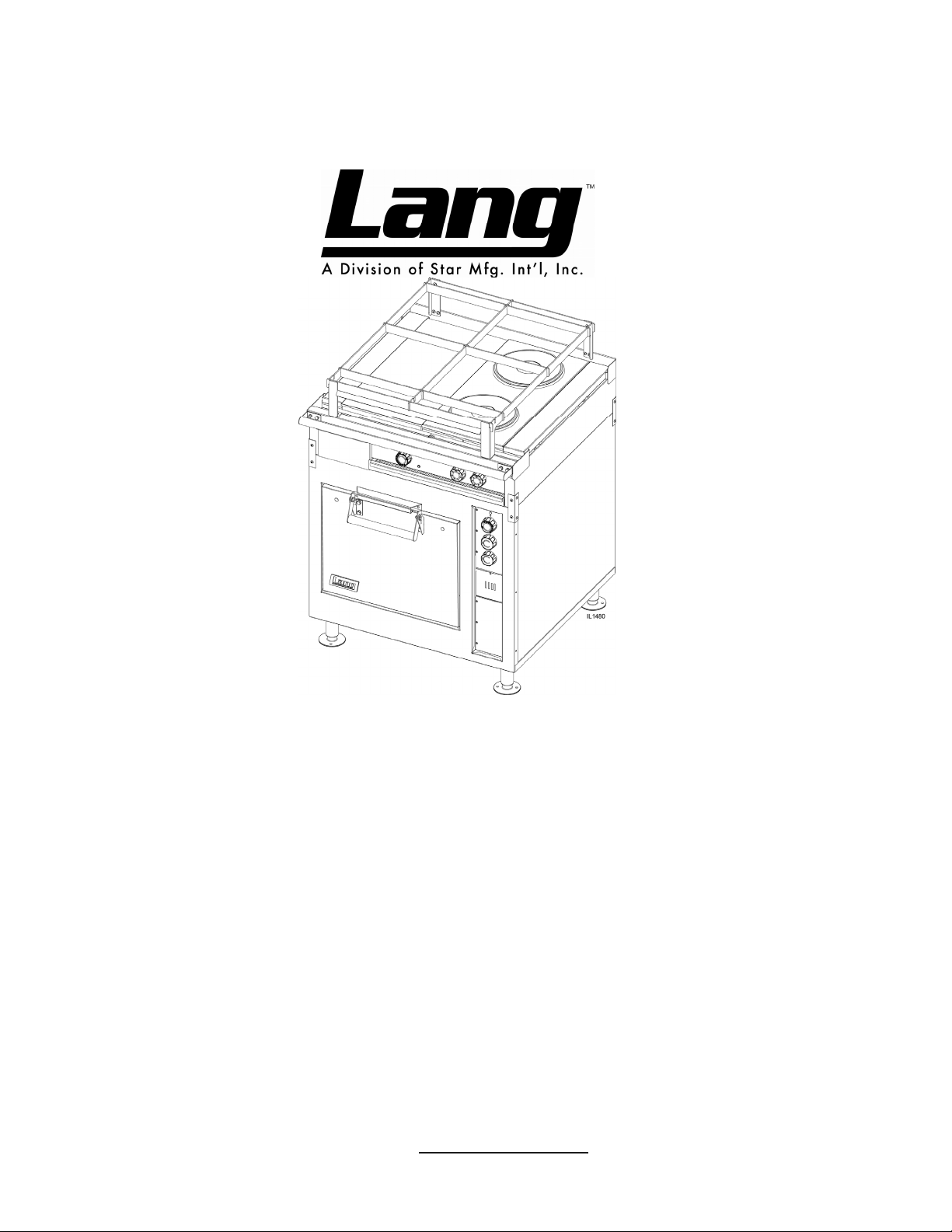
Electric Range
Model: R30S-M
Star Manufacturing International
Part Number: 2M-W1090
Rev C
265 Hobson Street
Smithville, Tennessee 37166
Ph: 800-264-7827 Fax: 314-781-2714
WWW.STAR-MFG.COM
11-2018
Page 2

SAFETY SYMBOL
Using any part other than genuine Star factory supplied parts relieves the
manufacturer of all liability.
Star reserves the right to change specications and product design without
notice. Such revisions do not entitle the buyer to corresponding changes,
improvements, additions or replacements for previously purchased
equipment.
Due to periodic changes in designs, methods, procedures, policies and
regulations, the specications contained in this sheet are subject to change
without notice. While Star International Holdings Inc., Company exercises
good faith efforts to provide information that is accurate, we are not
responsible for errors or omissions in information provided or conclusions
reached as a result of using the specications. By using the information
provided, the user assumes all risks in connection with such use.
These symbols are intended to alert the user to the presence of
important operating and maintenance instructions in the manual
accompanying the appliance.
RETAIN THIS MANUAL FOR FUTURE REFERENCE
NOTICE
MAINTENANCE AND REPAIRS
Contact your local authorized service agent for service or required maintenance.
Please record the model number, serial number, voltage and purchase date in the area below and have it ready when
you call to ensure a faster service.
Authorized Service Agent Listing
Model No.
Serial No.
Voltage
Purchase Date
Reference the listing provided with the unit
or
for an updated listing go to:
Website: www.star-mfg.com
E-mail Service@star-mfg.com
Service Help Desk
Business 8:00 am to 4:30 p.m. Central Standard Time
Hours:
Telephone:
Fax:
E-mail
Website:
(800) 264-7827
781-2714
(314)
Parts@star-mfg.com
Service@star-mfg.com
Warranty@star-mfg.com
www.star-mfg.com
Mailing Address: Star Manufacturing International Inc., Company
265 Hobson Street
Smithville, Tennessee 37166
U.S.A
2
Page 3

General Information
General
The range is designed to provide, well-regulated, uniform heat throughout the oven and over
the surface units. The oven and surface units should be thoroughly preheated before being
used. It is advantageous from an operating cost standpoint to operate with the switches and/or
thermostats set at the lowest position that will satisfactorily perform the cooking being done.
Electric range tops consist of several arrangements, depending upon the specific models
purchased.
Options include 12" x24" hot plates
Round speed units
Griddles
Three position switches, thermostats, or infinite controls independently control these units.
All thermostats are used in conjunction with a red indicator or pilot lamp. When the light is on
the elements are energized and bringing the plate to the temperature set on the thermostat.
When the light is off the plate has reached the temperature set on the thermostat. Griddle pilot
lights should be allowed to cycle a least twice before usage.
Recommended Usage:
12"x 24" hot plates - Heavy stockpots and kettles.
Round speed units - Light duty sauce pans and small stockpots. (NOT recommended for large
stockpots.)
Griddles - Used for grilling product directly on surface.
CAUTION
All hot plates and speed units should be turned to
the low or off position when not in use. Allowing
these elements to stay in the full on or high
position with nothing on top to absorb and
dissipate the heat is detrimental to element life.
3
Page 4

Operating Instructions
Initial Preheat
Before initial use, the oven must be allowed to dry itself out. This is completed by setting the
top and bottom oven switches to the “low” position, and setting the thermostat to 350
the range oven to saturate until all vapors and condensation have been eliminated. For best
operating results allow the range oven to thoroughly dry out. Allow eight (8) to twelve (12)
hours for this process. Clean the top plates thoroughly. Apply salad oil to the plates. Turn
each plate switch or thermostat to a low position and allow plate to heat for three hours.
Range Controls
Three (3) heat switches or automatic thermostats control the top plate units. The range is
provided with an upper heating unit located in the top of the oven and a lower heating unit
located under the metal deck, in the bottom of the oven. Each heating unit is independently
regulated for proper ratio of "top" and "bottom" heat, to suit the product being baked or
roasted, by means of two 3-heat switches located in the panel at the right of the range. The
range oven is also provided with an adjustable, automatic temperature control, the dial, which
is located in the range switch panel. The setting of the control dial establishes the average
temperature to be maintained in the range oven.
o
F. Allow
Operation
The range oven must be thoroughly, preheated before satisfactory baking can be done. The
range oven will not bake uniformly if not sufficiently preheated. To compensate for the
temperature drop when loading the range oven, set the thermostat fifty (50) degrees above the
desired temperature. Reset the thermostat after the range is loaded. Preheating of the range
oven can be accomplished with the heat switches set at a lower position than "High", but the
time will be proportionally longer. After preheating, set both three heat switches for proper ratio
of "top" and "bottom" heat to suit the product to be baked or roasted.
The 12" high "Roasting and Baking" range oven is equipped with a removable rack. For baking
pies, bread, or for roasting operations, the rack may be placed directly on the metal deck and
the pans placed on the rack. For baking cakes or pastries the rack should be located in the
lower position provided by the rack supports at the sides of the range and the pans placed on
the rack in this lower position.
4
Page 5

Range Top
12 x 24 Hot Plate or Round Speed Units controlled by three-heat switch, 6 - heat switch or high
temperature thermostats.
Round Speed Units, controlled by three - heat switch or six - heat switch. Recommended: Light
duty saucepans and small stock - pots. Not Recommended: Heavy stock - pots, or heavy urns,
or kettles.
o
12 x 24 or 24 x 24 Griddle plates, controlled by thermostats. Temperature range 450
Recommended: All heavy and light frying. Set the thermostat dial to the desired temperature.
The red pilot light will stay on until the desired temperature is reached. The pilot light indicates
when the plate is heating.
F.
5
Page 6

Maintenance
Daily Cleaning
WARNING
Burns could occur when dealing with hot grease!
Empty grease drawers daily or when the area under the grease shoot is full. Do not wait until
the entire grease drawer is full.
Clean the exterior of the range with hot water and a mild detergent to maintain a gleaming
appearance.
After each cooking load, scrape the griddle surface to remove any carbonized grease.
CAUTION
When scraping griddle surface, do not scrape the
splash guard. It may eventually be cut through.
Weekly Cleaning
The range should be thoroughly cleaned at least once a week in addition to the normal daily
cleaning to insure against the accumulation of foreign material. Keep inside of oven and metal
deck clean, particularly around door opening, door edges and at bottom of door opening so that
the door may close tightly.
6
Page 7

SPEED UNITS
1667
HEATING ELEMENT
1667
1667
1 2 4 3
1 2 4 3
2
3
1
4
6 HEAT
2 1 3 4
P1 P2
27
27
2 1 3 4
P1 P2
2 1 C
L1 L2
3 HEAT
SWITCH
SWITCH
8
7
FRENCH PLATES
HOT PLATE
3/28/2008
C
B
TOP SECTION WIRING DIAGRAMS
B
C
C
C
SECTION 2
A (18")
B
B
C
TOP ARRANGEMENT
SECTION 1
DESIGNATION
PREVIOUS MODEL
32S-1
32S-2 & 32S-2M(H)
32S-2M(G)
32S-3 & 32S-3M(H)
A (18")
A (30")
B
32S-4 & 32S-4M
32S-3M(G)
PILOT
LAMP
THERMOSTAT
EXAMPLE FOR DETERMINING THE WIRING OF A
GRILL (18" OR 30")
A
RANGE IS A (18") AND C (SEE TOP ARRANGMENT CHART).
LANG RANGE:
(1) VIEWED FROM THE FRONT, LEFT TO RIGHT, THE TOP
12 OR 18 INCH SECTIONAL ARRANGMENT FOR AN R30S-ATD
EACH OF THE LETTERS REPRESENT ONE OF THE TOP
ELEMENTS AND FOUR POWER INPUT LEADS.
30" SECTION - GRIDDLE OPTION ONLY - & HAS 2 HEATING
SECTION WIRING DIAGRAMS ABOVE. R30S-ATF IS ONE
(2)THE POWER INPUT LEADS TO EACH SECTION AND THE
OVEN ARE SHOWN AT LEFT CONNECTED TO THEIR
RESPECTIVE CIRCUIT BREAKERS.
CONNECTION OF CIRCUIT BREAKERS TO POWER
(3) SEE SERVICE CONNECTION CHART FOR PROPER
4
CIRCUIT
123
SUPPLY.
BREAKERS
2M-61101-10 Rev C
MODELS:
32Series Range 208-240 VOLT AC
R30 Series Range 208-240 VOLT AC
STAR MODEL
DESIGNATION
R30S-ATA
R30S-ATB
R30S-ATC
R30S-ATD
R30S-ATE
R30S-ATF
23
22
1
14
2 L2
16
15
OVEN WIRING DIAGRAM.
3 L1
PILOT
LAMP
17
NO REPRODUCTION OR DISCLOSURE OF ITS CONTENTS IS PERMITTED.
9
10
13
12
11
1
2 L2
18
19
3 L1
20
21
THIS DRAWING CONTAINS INFORMATION CONFIDENTIAL TO STAR MFG. INT'L. INC.
2
1, 3
L1
2, 4
L2
1,4
L1
3
L3
L2
SERVICE CONNECTION
PHASE
THREE
PHASE
SINGLE
Page 8

SPEED UNITS
1 2 4 3 1 2 4 3
1667
2
1667
3
1
4
1667
HEATING ELEMENT
TOP SECTION WIRING DIAGRAMS
PILOT
2 1 3 4
2 1 3 4
LAMP
P1 P2
P1 P2
2 1 C
3 HEAT
SWITCH
27
L1 L2
6 HEAT
SWITCH
27
3/28/2008
8
7
C
HOT PLATE FRENCH PLATES
2M-61101-07 Rev B
B
C
C
C
SECTION 2
A (18")
B
B
C
TOP ARRANGEMENT
SECTION 1
DESIGNATION
PREVIOUS MODEL
32S-1
32S-2 & 32S-2M(H)
32S-2M(G)
32S-3 & 32S-3M(H)
STAR MODEL
DESIGNATION
R30S-ATA
R30S-ATB
R30S-ATD
R30S-ATC
A (18")
A (30")
B
32S-4 & 32S-4M
32S-3M(G)
R30S-ATE
R30S-ATF
THERMOSTAT
22
EXAMPLE FOR DETERMINING THE WIRING OF A
GRILL (18" OR 30")
RANGE IS A (18") AND C (SEE TOP ARRANGMENT CHART).
LANG RANGE:
(1) VIEWED FROM THE FRONT, LEFT TO RIGHT, THE TOP
12 OR 18 INCH SECTIONAL ARRANGMENT FOR AN R30S-ATD
EACH OF THE LETTERS REPRESENT ONE OF THE TOP
ELEMENTS AND FOUR POWER INPUT LEADS.
30" SECTION - GRIDDLE OPTION ONLY - & HAS 2 HEATING
SECTION WIRING DIAGRAMS ABOVE. R30S-ATF IS ONE
(2)THE POWER INPUT LEADS TO EACH SECTION AND THE
OVEN ARE SHOWN AT LEFT CONNECTED TO THEIR
RESPECTIVE CIRCUIT BREAKERS.
CONNECTION OF CIRCUIT BREAKERS TO POWER
(3) SEE SERVICE CONNECTION CHART FOR PROPER
SUPPLY.
AB
CIRCUIT
123
9
10
22
PILOT
LAMP
13
12
11
BREAKERS
MODELS:
32Series Range 480VAC
R30 Series Range 480VAC
NO REPRODUCTION OR DISCLOSURE OF ITS CONTENTS IS PERMITTED.
THIS DRAWING CONTAINS INFORMATION CONFIDENTIAL TO STAR MFG. INT'L. INC.
1
14
2 L2
16
15
OVEN WIRING DIAGRAM.
3 L1
1
2 L2
18
17
19
3 L1
20
21
2
3
1
L3
L2
L1
SERVICE CONNECTION
Page 9

SPEED UNITS
1667
HEATING ELEMENT
1667
1667
1 2 4 3 1 2 4 3
2
3
1
4
6 HEAT
1 2 3 4
P1 P2
27
27
1 2 3 4
P1 P2
2 1 C
L1 L2
3 HEAT
SWITCH
SWITCH
8
7
3/28/2008
C
HOT PLATE FRENCH PLATES
2M-61101-12 Rev B
TOP SECTION WIRING DIAGRAMS
B
C
C
C
SECTION 2
A (18")
B
B
C
TOP ARRANGEMENT
SECTION 1
DESIGNATION
PREVIOUS MODEL
32S-1
32S-2 & 32S-2M(H)
32S-2M(G)
32S-3 & 32S-3M(H)
A (18")
A (30")
B
32S-4 & 32S-4M
32S-3M(G)
PILOT
LAMP
THERMOSTAT
22
THE FRONT, LEFT TO RIGHT, THE TOP
GRILL (18" OR 30")
EXAMPLE FOR DETERMINING THE WIRING OF A
AB
EACH OF THE LETTERS REPRESENT ONE OF THE TOP
(1) VIEWED FROM
12 OR 18 INCH SECTIONAL ARRANGMENT FOR AN R30S-ATD
30" SECTION - GRIDDLE OPTION ONLY - & HAS 2 HEATING
SECTION WIRING DIAGRAMS ABOVE. R30S-ATF IS ONE
ELEMENTS AND FOUR POWER INPUT LEADS.
RANGE IS A (18") AND C (SEE TOP ARRANGMENT CHART).
LANG RANGE:
(2)THE POWER INPUT LEADS TO EACH SECTION AND THE
OVEN ARE SHOWN AT LEFT CONNECTED TO THEIR
RESPECTIVE CIRCUIT BREAKERS.
123
9
10
22
BREAKERS
PILOT
LAMP
CIRCUIT
N
L1 L2 L3
MODELS:
32Series Range: 220/380V & 240/415V, 3Ph, 4-wire
R30 Series Range: 220/380V & 240/415V, 3Ph, 4-wire
STAR MODEL
DESIGNATION
R30S-ATA
R30S-ATB
R30S-ATC
R30S-ATD
R30S-ATE
R30S-ATF
1
14
2 L2
16
15
OVEN WIRING DIAGRAM
3 L1
13
12
11
1
2 L2
18
17
19
3 L1
20
21
NO REPRODUCTION OR DISCLOSURE OF ITS CONTENTS IS PERMITTED.
THIS DRAWING CONTAINS INFORMATION CONFIDENTIAL TO STAR MFG. INT'L. INC.
Page 10

SPEED UNITS
1667
HEATING ELEMENT
1667
1667
34 35
33
32
31
30
29
1 2 4 3 1 2 4 3
28
2
3
1
4
6 HEAT
1 2 3 4
P1 P2
27
27
1 2 3 4
P1 P2
2 1 C
L1 L2
3 HEAT
SWITCH
SWITCH
8
7
3/28/2008
C
HOT PLATE FRENCH PLATES
TOP SECTION WIRING DIAGRAMS
B
C
C
C
SECTION 2
A (18")
B
B
C
TOP ARRANGEMENT
SECTION 1
DESIGNATION
PREVIOUS MODEL
32S-1
32S-2 & 32S-2M(H)
32S-2M(G)
32S-3 & 32S-3M(H)
A (18")
A (30")
B
32S-4 & 32S-4M
32S-3M(G)
PILOT
LAMP
THERMOSTAT
22
GRILL (18" OR 30")
EXAMPLE FOR DETERMINING THE WIRING OF A
AB
22
PILOT
LAMP
EACH OF THE LETTERS REPRESENT ONE OF THE TOP
ELEMENTS AND FOUR POWER INPUT LEADS.
(1) VIEWED FROM THE FRONT, LEFT TO RIGHT, THE TOP
12 OR 18 INCH SECTIONAL ARRANGMENT FOR AN R30S-ATD
30" SECTION - GRIDDLE OPTION ONLY - & HAS 2 HEATING
SECTION WIRING DIAGRAMS ABOVE. R30S-ATF IS ONE
9
10
RANGE IS A (18") AND C (SEE TOP ARRANGMENT CHART).
LANG RANGE:
(2)THE POWER INPUT LEADS TO EACH SECTION AND THE
OVEN ARE SHOWN AT LEFT CONNECTED TO THEIR
RESPECTIVE CIRCUIT BREAKERS.
CONNECTION OF CIRCUIT BREAKERS TO POWER
(3) SEE SERVICE CONNECTION CHART FOR PROPER
123
SUPPLY.
CIRCUIT
BREAKERS
2M-61101-14 Rev C
MODELS:
32Series Range: 380V
R30 Series Range: 380V
STAR MODEL
DESIGNATION
R30S-ATA
R30S-ATB
R30S-ATC
R30S-ATD
R30S-ATE
R30S-ATF
1
14
2 L2
16
15
OVEN WIRING DIAGRAM
3 L1
13
12
11
1
2 L2
18
17
19
3 L1
2
3
1
20
21
L3
L2
L1
SERVICE CONNECTION
NO REPRODUCTION OR DISCLOSURE OF ITS CONTENTS IS PERMITTED.
THIS DRAWING CONTAINS INFORMATION CONFIDENTIAL TO STAR MFG. INT'L. INC.
Page 11

Page 12

SK2355 Rev. - 3/6/07
Model:
R30S-Marine Range Top Assy
1
2
3
7
3
8
9
10
14
16
17
18
11
12
6
4
5
Old Style
See Control
Panel Detail
4 5 18
Suggested
Parts Stocking
Page 13

PARTS LIST October 4, 2012 Rev -
Model No: R30S-ATA, R30S-ATB, R30S-ATC, R30S-ATD, R30S-ATE, R30S-ATF, Marine 30” Electric
Range Top Assy
Fig No Part No. Qty Description Application
P9-50302-302
1
P9-50302-304 SEARAIL ASSY 1’ RT30 ATD, ATE
P9-50401-15-3
2
P9-50401-17-1 RANGE PLT MOD 1/2 X 30 ATF
3 N9-32-332 2 3 INCH SPREADER-PLATE ATA, ATB, ATC
PS-11010-341
4
PS-11010-351
PS-11010-361
2N-11120-12
2N-11120-13
5
2N-11120-14
2N-11120-18 4 ELMNT TK 380V 2000W ATA-380V
6 P9-50300-82-2
7 P9-CR30-258 1 DRAWER COVER ALL
P9-50302-20 1 GRAB BAR ASSY/CR30-M ALL
2C-20111-01
8
2C-20204-02 WASHER SS 1/4 SPLIT LOCK GRAB BAR MOUNTING HRD
2C-20303-01 NUT HX SS 1/4-20 GRAB BAR MOUNTING HRD
9 N9-32-326 4 BODY WRAP ANGLE - 2 PIECE ALL
10 2C-20115-06 8 SCRW S/S 8-32X1/2 T/H S/T ALL
11 P9-CR30-280 1 LARGE DRAWER ASSY ALL
12 P9-CR30-260 1 SPOT SMALL DRAWER ALL
14 K9-XL-504 1 STAT HOLDER ATD, ATE
14 K9-XL-504 4 STAT HOLDER ATF
16
17
18
NI 2H-CR30-326 1 ELMNT PAN INSULATION 18 GRIDDLE ATD, ATE
NI 2H-CR30-328 2 ELMNT PAN INSULATION 30 GRIDDLE ATF
P9-CR30-320 1 ELMNT PAN ASSY 18” ATD, ATE
P9-CR30-329 4 ELMNT PAN ASSY 30 ATF
P9-CR30-325 1 ELMNT PAN Z 18” GRIDDLE ATD, ATE
P9-CR30-327 4 ELMNT PAN Z 30” GRIDDLE ATF
2N-11030-45 1 ELMNT GRID 18” RANGE 208V ATD208V, ATE208V
2N-11030-55 2 ELMNT GRID 30” RANGE 208V 5.5KW ATF208V
2N-11030-46 1 ELMNT GRID 18” RANGE 240V ATD240V, ATE240V
2N-11030-55 2 ELMNT GRID 30” RANGE 240V 5.5KW ATF240V
2N-11030-47 1 ELMNT GRID 18” RANGE 480V ATD440/480V, ATE440/480V
SEARAIL ASSY 2’ RT30 ATA, ATB, ATC
1
RANGE PLTE ASY 18 SHORT ATD, ATE
1
1
KIT, HOTPLATE 208V 500W
2 ATC-208V
1
KIT, HOTPLATE 240V 5000W
2 ATC-240V
1
KIT, HOTPLATE 480V 500W
2 ATC-440/480V
2
ELMNT TK 208V 2600W
4 ATA-208V
2
ELMNT TK 240V 2600W
4 ATA-240V
2
ELMNT TK 480V 2600W
4 ATA-440/480V
1
EGOPLTE FRMEASY PHANT 32/
2 ATA
SCRW HXHD CAP 1/4-20X1/2 GRAB BAR MOUNTING HRD
4
ATB208V, ATE208V
ATB240V, ATE240V
ATB440/480V, ATE440/480V
ATB208V, ATD240V
ATB-240V, ATD-240V
ATB-440/480V
ATB
Page 14

1
2
17
18
16
19
20
21
13
14
14
13
15
15
15
24
15
22
23
6
7
10
11
3
4
5
8
9
12
7 8 9 10
4
11 13 14 22
Suggested Parts Stocking
Model:
R30S-Marine Range Oven Assy
SK2356 Rev. - 3/6/07
Page 15

PARTS LIST October 4, 2012 Rev -
Model No: R30S-ATA, R30S-ATB, R30S-ATC, R30S-ATD, R30S-ATE, R30S-ATF,
Marine 30” Electric Range Oven Assy
Fig No Part No Qty Description Application
1 N9-32-143 1 BODY SIDE LOWER L/H - 2 ALL
Y9-50300-14 1 MARINE HANDLE CHANNEL ALL
2
3 N9-32-142 1 BODY SIDE LOWER R/H - 2 ALL
4
5 2E-31200-02 1 LUG GROUNDING UL APPROVED ALL
6 Y9-31200-02-1 1 GROUNDING LUG/+LABEL ALL
7
8 2T-30402-08 1 STAT ADJ 450o 72 C/T ALL
9 2E-30304-35 2 SWTROT3HT 240/480VAC20AMP ALL
10
11
12 2A-72500-05 4 LEG 4 W/BOLT DOWN ADJ ALL
13
14
15 2C-20301-15 8 NUT HEX 10-32 PLTD ALL
16 K9-60301-43-1 1 DIE CAST LOG + TINNERMAN ALL
17 Y9-50300-11 1 MARINE HANDLE ALL
18 2P-70903-01 4 PLG BTN PLTD MTL 3/8 ALL
19 N9-32-229 1 DOOR ASSEMBLY WITH A/L IS ALL
20 2C-20102-04 4 SCRW PHD ST 8-32X.5 PLTD ALL
21 N9-LA36-109-1 1 CAPILLARY SHIELD ALL
22 N9-32-131 1 SWITCH DOOR ASSY ALL
23 2A-32-124 1 SWITCH DOOR HINGE ROD ALL
24 N9-32-437 1 OVEN DECK WELD ALL
2C-20101-10
2C-20204-02 WASHER SS 1/4 SPLIT LOCK MARINE HANDEL MOUNTING
2C-20301-29 NUT HEX ACORN 1/4-20 SS MARINE HANDEL MOUNTING
2E-31601-02 1 CB 480V 50A 3 POLE 380V
2E-31800-01 4 CB 250V50A 1 POLE CRLNGSW 208,240V
2E-31800-04 1 CB 480V 50A 3 POLE 440V, 480V
2J-31601-01 1 PILOT LT 250V 6LEAD BLK 208/240V
2J-31601-02 1 PILOT LT 480V 6LEAD BLK 380V, 440V, 480V
Y9-70701-16 1 KNOB ASSY 450°F, BLACK
Y9-70701-16-2 1 KNOB ASSY 450°F, RED
Y9-70701-10
Y9-70701-10-2 KNOB 3-HEAT 208-240V, RED
2N-11040-02
2N-11040-08 ELMNT 32OVEN 480V O/S 1KW 440V, 480V
2N-11040-18 ELMNT 32OVEN 380V O/S 1KW 380V
2N-11040-01
2N-11040-07 ELMNT 32OVEN 480V I/S 1KW 440V, 480V
2N-11040-17 ELMNT 32OVEN 380V I/S 1KW 380V
SCREW THD MS 1/4-20X2 1/4 PL MARINE HANDEL MOUNTING
2
KNOB 3-HEAT 208-240V, BLACK
2
ELE 32OVN 208/240V OS 1KW 208/240V
2
ELE 32OVN 208/240V IS 1KW 208/240V
2
Page 16

Part No. Qty Description
50302-304-1 SEARAIL ASSY 1’ RT30 SK
A 50302-307 1 SEARAIL LH SIDE RT30
B 50302-308 1 SEARAIL RH SIDE RT30
C 50302-317 5 SEARAIL SIDE TO SIDE 12”
20109-04 6 SCREW THD MS SS 10-32X 3/8
Part No. Qty Description
50302-302-1 SEARAIL ASSY 2’ RT30/32 SK
A 50302-307 1 SEARAIL LH SIDE RT30
B 50302-308 1 SEARAIL RH SIDE RT30
C 50302-317 6 SEARAIL SIDE TO SIDE 12”
D 50302-316 1 SEARAIL FR TO BK RT30
E 50302-311 2 SEARAIL FR & RR 2’
20109-04 6 SCREW THD MS SS 10-32X 3/8
20301-34 2 NUT HEX ACORN 10-32 S/S
C
B
A
D
E
A
C
B
E
Page 17

1
2
1
4
10
4
8
8
8
16
9
13
14
13
16
6
8
7
R30S-ATB
2
4
11
13
10
9
16
R30S-ATA
2
4
16
16
8
9
6
7
13
14 15
16
13
R30S-ATD
8
10
15
6
7
8
13
12
14
R30S-ATC
Suggested Parts Stocking
106 11 13 14
Model:
R30S Marine Range Top Controls
SK2357 Rev. - 3/7/08
Page 18

3
3
2
4
4
10
15
8
141613
13
1416
11
15
12
8
16
6
7
8
16
14
13
R30S-ATE
11
15
R30S-ATF
14
12
15
8
6
7
Suggested Parts Stocking
106 11 13 14
Model:
R30S Marine Range Top Controls
SK2358 Rev. - 3/7/08
Page 19

PARTS LIST October 4, 2012 Rev -
Model No: R30S-ATA, -ATB, -ATC, -ATD, -ATE, -ATF, Marine 30” Range Control Top Panel Assy
Fig No Part No Qty Description Application
1
2
3
4 P9-CR30-222 1 CONTROL BACK ATA, ATB, ATC, ATD, ATE, ATF
6 2E-30500-08 1 TRM BLOCK 2 POLE SMALL 95 ATB, ATC-480VM ATD, ATE, ATF
7 2C-20103-07 2 SCRW PHD SM 8X1 PHL TYP A ATB, ATC, ATD, ATE, ATF, RT30G
8 2C-20115-06 4 SCRW S/S 8-32X1/2 T/H S/T ATA, ATB, ATC, ATD, ATE, ATF
9
10
11
12
13
14
15
16
P9-CR30-750 1 CONDUIT ASSY - SPEED UNIT ATB, ATE
P9-CR30-750 2 CONDUIT ASSY - SPEED UNIT ATA
P9-CR30-752 1 CONDUIT ASSY - HOT TOP ATB, ATE
P9-CR30-752 2 CONDUIT ASSY - HOT TOP ATC, ATD
P9-CR30-751 1 CONDUIT ASSY - GRIDDLE ATE
P9-CR30-751 2 CONDUIT ASSY - GRIDDLE ATF
2E-30304-09 2 SWTROT 6 HEAT+OFF208/240V ATB, ATD, RT30G
2E-30304-09 4 SWTROT 6 HEAT+OFF208/240V ATA
2T-30402-23 1 STAT ADJ 850o 48C/T NAK ATB, ATE
2T-30402-23 2 STAT ADJ 850o 48C/T NAK ATC
2T-30402-08 1 STAT ADJ 450o 72 C/T ATD, ATE
2T-30402-08 2 STAT ADJ 450o 72 C/T ATF
P9-CR30-311 1 CONTROL FRONT SS ATA
P9-CR30-312 1 CONTROL FRONT HS & GS ATB, ATD
P9-CR30-313 1 CONTROL FRONT HH ATC, ATE, ATF
P9-70701-38
P9-70701-38-2
P9-70701-41
P9-70701-41-2
Y9-70701-19
Y9-70701-19-2
2J-31601-01 1 PILOT LT 250V 6LEAD BLK ATD-208V
2J-31601-01 2 PILOT LT 250V 6LEAD BLK ATC-208V, ATE-208M, ATF-208/240M
2J-31601-02 1 PILOT LT 480V 6LEAD BLK ATB-480M, ATD-440/480M
2J-31601-02 2 PILOT LT 480V 6LEAD BLK ATC-480M, ATF-440/480M
2C-20602-03 1 TINNERMAN 3SCLIP 5/16 ATB-480M, ATD-208M
2C-20602-03 2 TINNERMAN 3SCLIP 5/16 ATC
2C-20101-64 4 SCRW PHD MS M4 X 6 PLTD ATB, ATD
2C-20101-64 8 SCRW PHD MS M4 X 6 PLTD ATA
2C-20109-09 2 SCRW THD MS SS 6-32X1/4 ATB, ATD
2C-20109-09 4 SCRW THD MS SS 6-32X1/4 ATE
2C-20109-09 4 SCRW THD MS SS 6-32X1/4 ATC, ATF
1
2 ATC
1
2 ATC
2
4 ATA
2
4 ATA
1
2 ATF
1
2 ATF
KNOB 850o D, BLACK
KNOB 850o D, RED
KNOB 6 HEAT EGOTK, BLACK
KNOB 6 HEAT EGOTK, RED
KNOB 450o D, BLACK
KNOB 450o D, RED
ATB, ATE
ATB, ATE
ATB, ATD
ATB, ATD
ATD, ATE
ATD, ATE
Page 20

STAR MANUFACTURING INTERNATIONAL INC.
Star - Holman - Lang - Wells - Bloomeld - Toastmaster
265 Hobson Street Smithville, Tennessee 37166 U.S.A.
(800) 264-7827
www.star-mfg.com
 Loading...