

Page 1
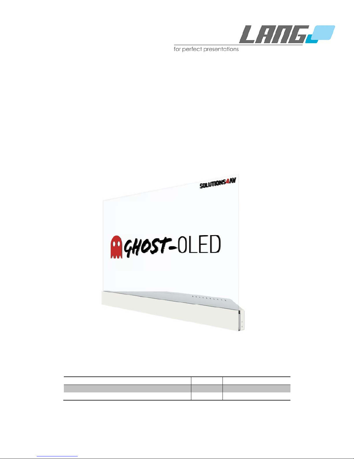
GhosT-OLED Series
Manual
Date Revision No.
Author
1st
Check
Final Check
Description
28.09.2016
1.0 BVT/TSN/DWN TSN First Draft
Page 2
2
TABLE OF CONTENT
1. Important information 4
1.1 Safety instructions 4
1.2 Damage prevention 4
1.3 Operating conditions 5
2. Overview GhosT-OLED Series 5
2.1 Introduction 5
2.1.1 GhosT-OLED-I (Installation) 6
2.1.2 GhosT-OLED-PT (primeTOUCH) 6
2.2 GhosT-OLED Setup Versions 7
2.2.1 GhosT-OLED Table-Stand Version (TV) 7
2.2.2 GhosT-OLED Straight Version (SV) 7
2.2.3 GhostT-OLED Straight Offset Version (SOV) 8
3. Scope of delivery 9
4. Pack-/ and unpack-instructions 10
4.1 Table-Stand Version 10
4.2 Straight Version & Straight Offset Version 12
5. Installation instructions 14
5.1 Mechanical installation 14
5.1.1 Installations tools and materials 14
5.1.2 Screw hole pattern 15
5.2 Installation possibilities 16
5.2.1 GhosT-OLED Table-Stand Version 16
6. Connector panel and control possibilities 19
6.1 Power Input, IR-Receiver and optional touch 19
6.2 Video input connectors 20
6.3 Local control 21
6.4 External Control Connectors 21
6.4.1 Remote control 22
6.4.2 On-Screen-Display (OSD) menu guide 23
6.4.3 Web interface 24
7. primeTOUCH option 25
8. Content Guide 25
8.1 Pixel Shift 25
8.2 Transparency 26
8.3 Static content 26
Page 3
3
9. Troubleshooting 27
10. Specifications 27
11. Product outlines 29
11.1 Drawings GhosT-OLED-I 29
11.1.1 Table-Stand Version 29
11.1.2 Straight Version 30
11.1.3 Straight Offset Version 31
11.2 Drawings GhosT-OLED-PT 32
11.2.1 Table-Stand Version 32
11.2.2 Straight Version 33
11.2.3 Straight Offset Version 34
12. Certification 35
Note: These installation instructions must always be handed over to the installing person
1
Note: Read these instructions carefully before installing the system
Copyright © 2016 LANG AG. All rights reserved.
1
Only a qualified person should install this product
Page 4
4
1. Important information
The GhosT-OLED series has been designed under the highest attention on safety. However, improper
handling can cause a risk for safety and/ or damage. Please read carefully the instructions provided in
this manual in order to avoid damage and ensure personal safety. Heeding the instructions will also
prevent image retention and extend the products lifetime. The GhosT-OLED products are intended for
use by fully qualified, trained and competent persons as an aid to provide safe and secure
installations.
1.1 Safety instructions
• Do not open the housing of the display otherwise electric shocks may occur. There is no need
for users to open the housing of the display. Please refer to Lang-AG for any service works.
• Do not expose the screen to water or moisture to prevent electric shocks.
• If the screen or the housing breaks, be very careful as broken fragments may cause injuries.
Do not touch broken glass with bare hands, use appropriate safety tools
• If the screen or the housing is broken, always unplug all power supplies and other cables from
the display to prevent electric shocks.
• Do not use the system in other operating conditions than described in chapter 1.3 Operating
conditions.
• In cause of injury, for example caused due to contact with broken glass, please seek medical
help immediately
• Do not mount the GhosT-OLED displays to unstable structures, the entire system might fall
down or tilt over. Make sure that the construction to which a display is mounted can support
the given total weight (for weight details please referr to: 10.Specifications)
1.2 Damage prevention
• Do not expose the screen to water or moisture to prevent any damage.
• Avoid any force or impacts on the screen.
• If the screen is broken, always unplug all power supplies and other cables from the display to
prevent damage to electronical parts.
• Set up the screen in a well ventilated place.
• The recommended operating time is less than 12 hours a day.
• Static images on the display can cause image retention. To prevent such damage, it is
recommended to show dynamic content periodically. Refer to 19. Content recommendations
for furthermore information.
• Do not expose the display to sunlight or any UV light sources as UV light can cause damage
to the screen.
• Always operate the system under the specified operating conditions described in chapter 1.3
Operating conditions.
Page 5
5
1.3 Operating conditions
• Temperature: 25 +/-10°C
• Humidity: 55 +/-20% rH
• Operating time: less than 12 hours a day
• Display pattern should be changing continuously to avoid any kind of image retention
• No sunlight or any other warm light sources directed onto the screen
• Only indoor operation
• Display must be protected from UV light
• Usage only in well ventilated environments
2. Overview GhosT-OLED Series
2.1 Introduction
Displays from GhosT-OLED series are transparent OLED (T-OLED) screens in Full-HD resolution
with low temperature poly silicon TFTs. The transmittance of the screen is approx. 45% (excluding
cover glass). Thanks to OLED (Organic Light Emitting Diode) technology, the display shows
excellent images even at high viewing angles and has very low power consumption. The
transparency is achieved by adding a fourth segment into the sub pixel structure which usually
consists of three sub pixel emitting red, green and blue light. This fourth segment is transparent
and compared to the other sub pixel the largest one. As OLED is a self-emitting technology, there
is, unlike to LCDs, no need for backlight. Displaying black content on a transparent OLED display
will make this content appear transparent. GhosT-OLED displays are bonded with an anti-
reflective, tempered front glass and are optionally available with a primeTOUCH system based on
IR diodes. GhosT-OLED displays can be delivered with white or black housing.
The GhosT-OLED series is based on a customizable design concept. There are two different
versions available, each with three variable ways to install them. With this portfolio GhosT-OLED
Series offers a standard solution for many applications.
Page 6
6
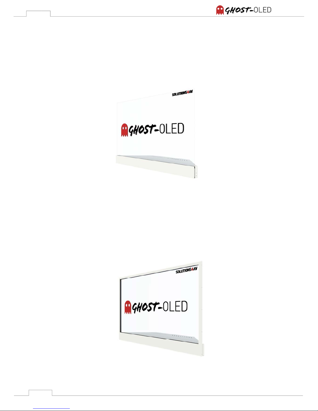
2.1.1 GhosT-OLED-I (Installation)
This version provides a frameless glass surface, thinner than 9 mm. With its frameless but robust
design the GhosT-OLED-I version is perfect for exclusive, futuristic installations. The display is
available in each of the three installation options whereby the Table-Stand Version is pictured
below.
Figure 1: GhosT-OLED-I, TV Option
2.1.2 GhosT-OLED-PT (primeTOUCH)
This version combines the advantages of the T-OLED technology with the multi touch capable
primeTOUCH technology. Despite touch capability it provides a narrow but stable frame. The
display is available in each of the three installation options whereby the Table-Stand Version is
pictured below.
Figure 2: GhosT-OLED-PT, TV Option
Page 7
7
2.2 GhosT-OLED Setup Versions
The three different setup versions for GhosT-OLED-I and -PT will be described briefly in the following
passage. Please note: All images present the GhosT-OLED-I, but basically the same applies also to
GhosT-OLED-PT.
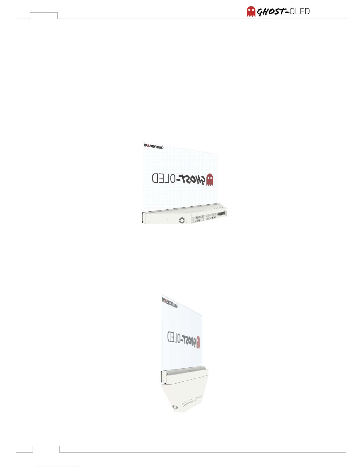
2.2.1 GhosT-OLED Table-Stand Version (TV)
For flexible use and fast setup the Table-Stand Version is recommended. Mounting points on the
bottom side of the display enable portrait mode, face up installations and setups to angled
surfaces. The design of the table foot allows convex display arrays with angles up to 90°.
Figure 3: GhosT-OLED-I, TV Option, backside
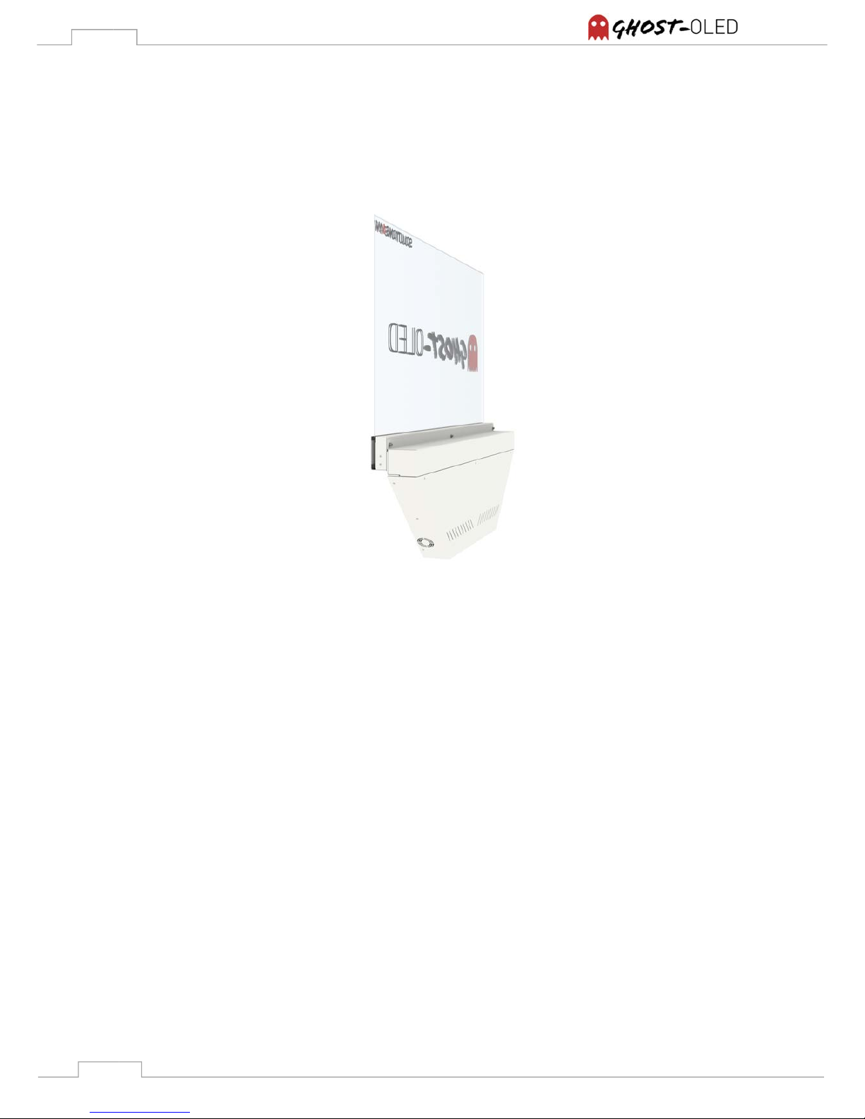
2.2.2 GhosT-OLED Straight Version (SV)
The Straight Version is designed for space-saving installations like in podiums, balustrades or
counters. It’s quick and easy to install by using the mounting points in the front.
Figure 4: GhosT-OLED-I, SV Option, backside
Page 8
8
2.2.3 GhostT-OLED Straight Offset Version (SOV)
The straight-offset version provides all the advantages of the Straight Version with an additional
mounting surface for leveled installations. It uses the same mounting points as the Straight
Version.
Figure 5: GhosT-OLED-I, SOV Option, backside
Page 9
9
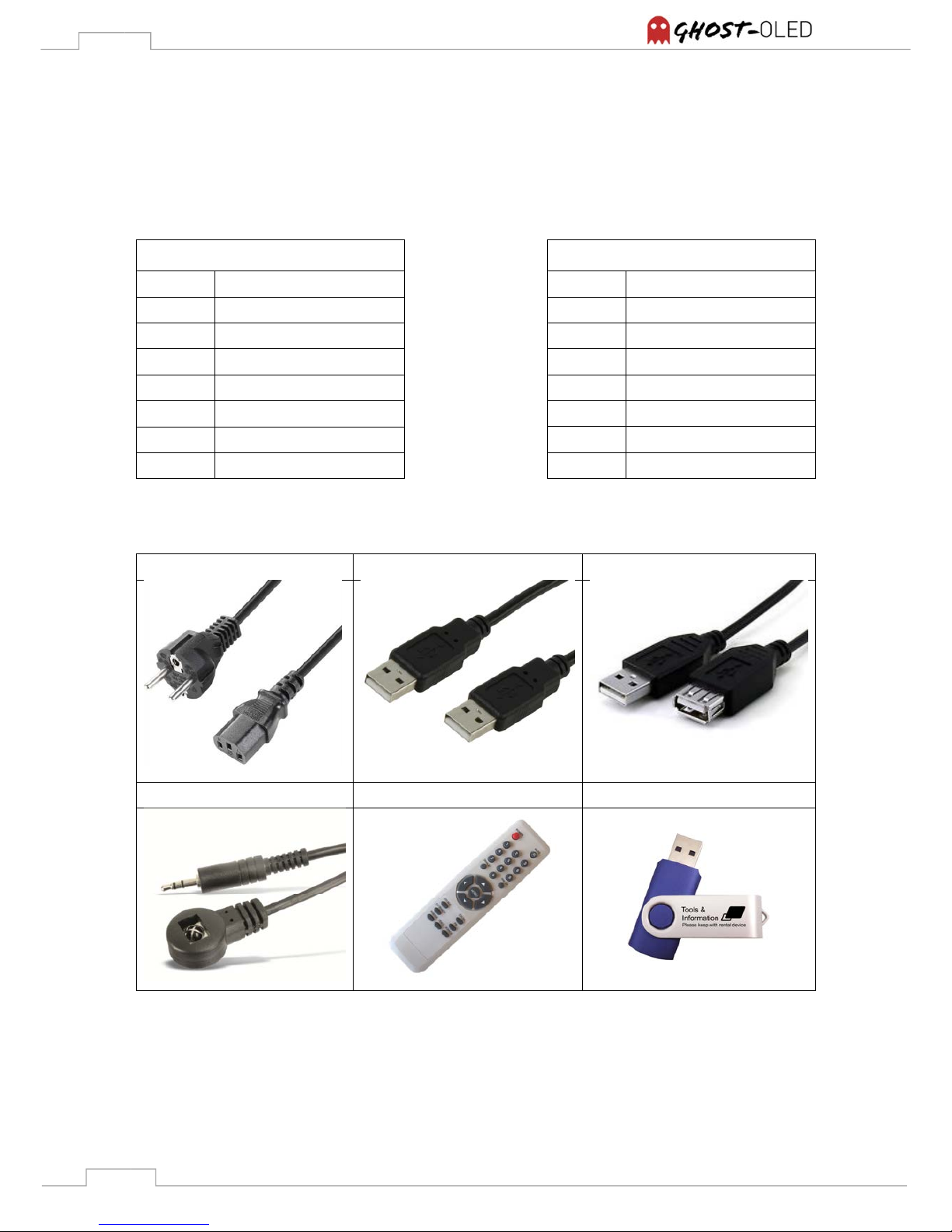
3. Scope of delivery
Note: Please check the delivery for completeness and damage immediately after you receive the
shipment. Please contact your supplier in case of missing or damaged parts.
Power cable USB cable USB extender
External IR-sensor Remote control USB stick
Illustrated list of mentioned accessories
GhosT-OLED-I delivery scope
Quantity Item
1 GhosT-OLED-I
1 Power cable
1 Remote control
1 External IR-Receiver
1 USB stick (tools & info)
GhosT-OLED-PT delivery scope
Quantity Item
1 GhosT-OLED-PT
1 Power cable
1 Remote control
1 External IR-Receiver
1 USB stick (tools & info)
1 USB cable (A type)
1 USB extender (A type)
Page 10
10
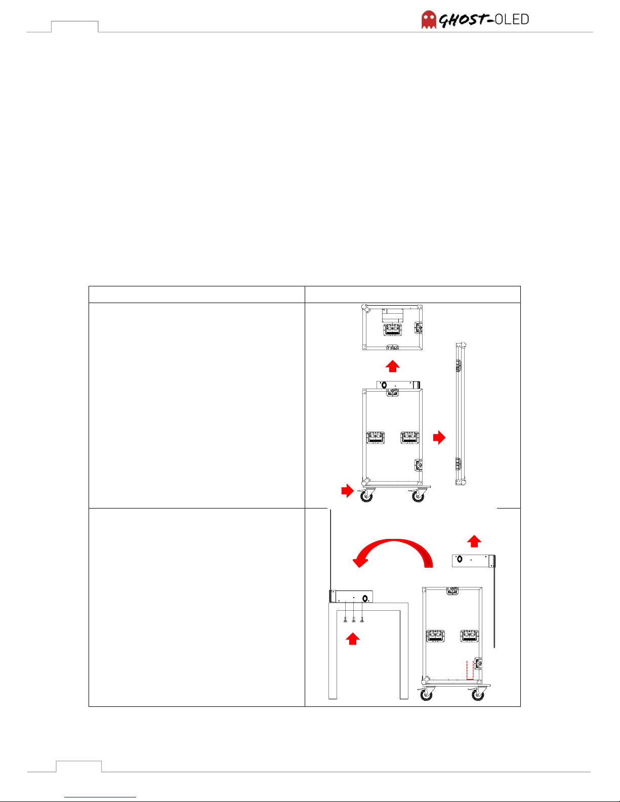
4. Pack-/ and unpack-instructions
GhosT-OLED units get shipped in a functional flight case designed for all three installation versions.
Caused by the universality the units get inserted upside down.
Note: Read the following instructions carefully to prevent injuries to humans or damages to the
system and environment.
Note: GhosT-OLEDs provided as straight-/ or straight-offset version have to be mounted right after
unpacking. There is no possibility to place them on a table or on the floor intermediately.
Note: For packing and unpacking a unit at least two persons are required.
4.1 Table-Stand Version
Description Illustration
1. Make sure that the brakes of the flight
case are tightened
2. Open the front cover of the flight case
3. Open the top cover of the flight case
1. Lift the unit out of the flight case
carefully by considering the guiding slot
on the bottom side of the flight case
2. Rotate the unit by 180° degrees and set
it down carefully
3. Attach the display to the exhibition
furniture referring to 5 Installation
instruction
2 3
1
2 3
GuidingSlot
1
Page 11
11
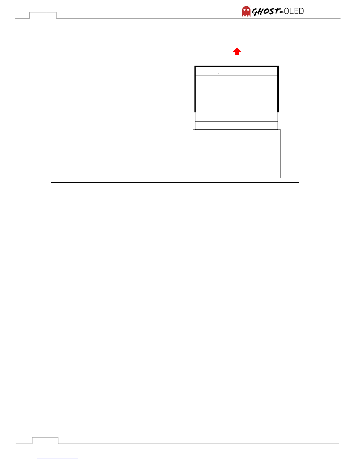
1. The glass surface of the GhosT-OLED-I
version is protected with an additional
foam cover. Remove the cover carefully
and store it safely.
Note: For packing follow the provided steps backwards
1
Glass surface
Foam cover
User side
Page 12
12
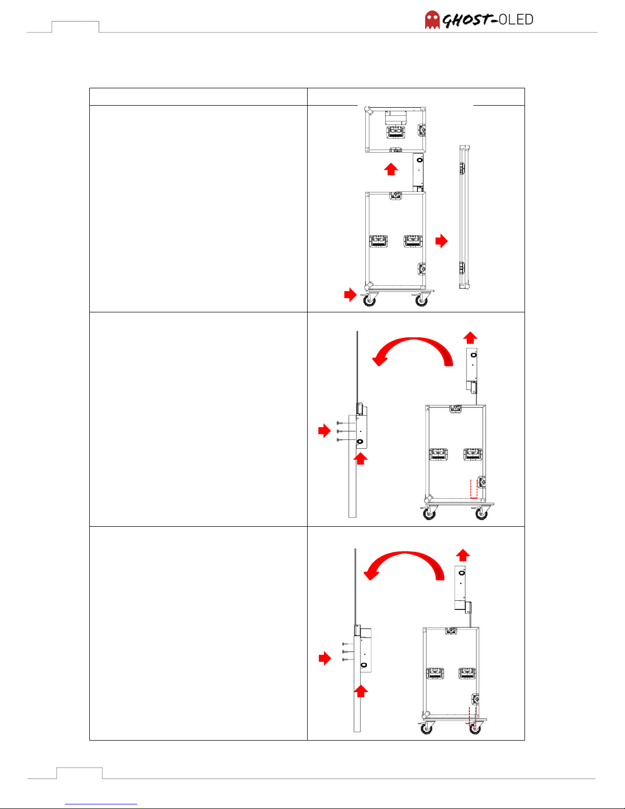
4.2 Straight Version & Straight Offset Version
Description Illustration
1. Make sure that the brakes of the flight
case are tightened
2. Open the front cover of the flight case
3. Open the top cover of the flight case
Straight Version
1. Lift the unit out of the flight case
carefully by considering the guiding slot
on the bottom side of the flight case
2. Rotate the unit by 180° degrees
3. Align the unit to the construction of the
exhibition furniture carefully
4. Attach the unit to the exhibition furniture
referring to 5 Installation instruction
Straight Offset Version
1. Lift the unit out of the flight case
carefully by considering the guiding slot
on the bottom side of the flight case
2. Rotate the unit by 180° degrees
3. Align the unit to the construction of the
exhibition furniture by using the angled
mounting surface
4. Attach the unit to the exhibition furniture
referring to 5 Installation instruction
Guiding
Slot
2
3
1 1 2
3
4
Guiding
Slot
1 2
3
4
Page 13
13
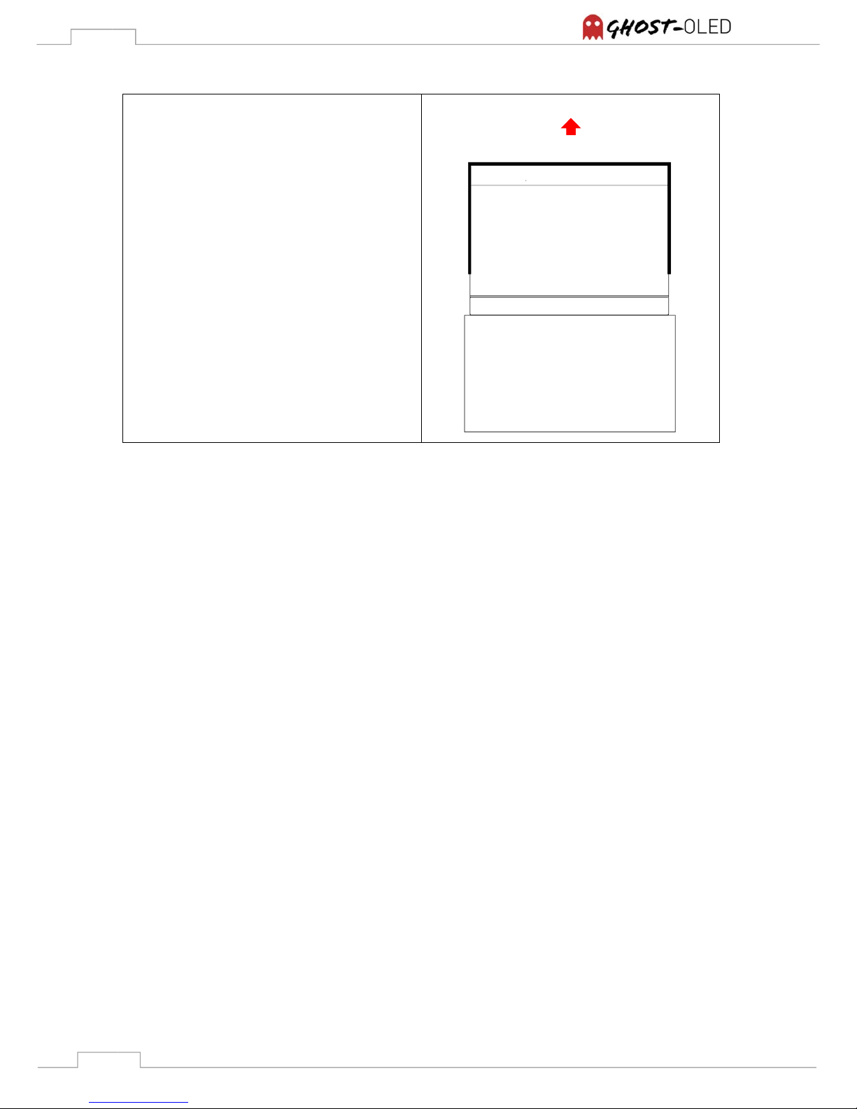
1. The glass surface of the GhosT-OLED-I
version is protected with an additional
foam cover. Remove the cover carefully
and store it safely.
Note: For packing follow the provided steps backwards.
1
Glass surface
Foam cover
User side
Page 14
14
5. Installation instructions
5.1 Mechanical installation
All versions of the GhosT-OLED series are based on the same housing system which makes them
easy and fast to setup. Before you start installing the screen, follow the instructions provided in 3
Scope of delivery and 4 Pack-/ and unpack-instructions.
Note: Read the following instructions carefully to prevent injuries to humans or damages to the
system.
Note: For mounting the GhosT-OLED at least three persons are required.
Note: Use only the required tools and mounting materials.
5.1.1 Installations tools and materials
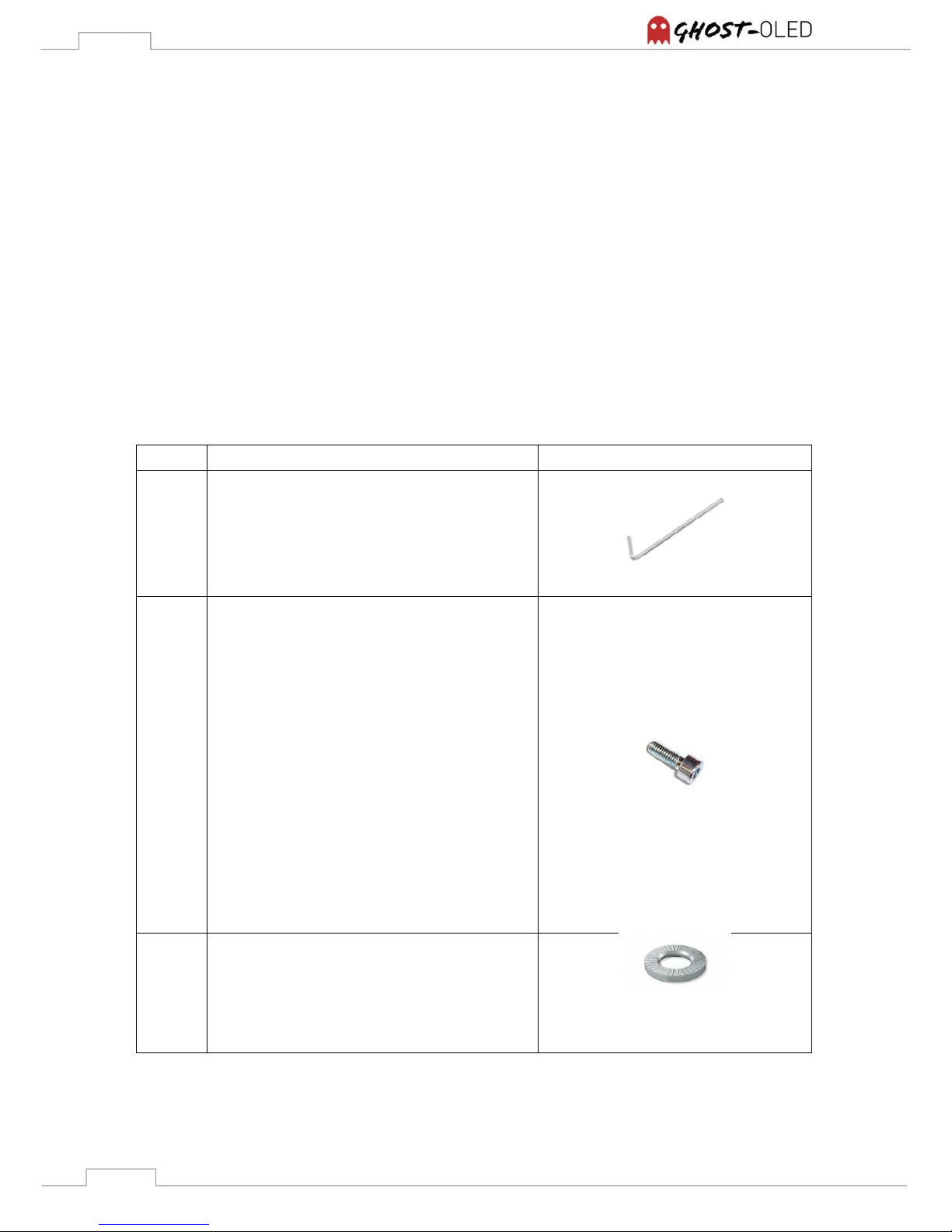
Quantity Description Illustration
1
• 5mm HEX key
up to 14
• M6 x 16 mm + surface thickness
Note: The screw size always needs to be
16 mm longer than the surface thickness of
the exhibition furniture.
Note: The head shape of the screw
depends on the conditions of the mounting
area.
Note: The number of available screw holes
depends on the given version and
installation option.
Note: Min. 8 screw holes have to be used
up to 14
• 6,4 mm washers
Note: The use of safety washers is
recommended in most cases. This depends on
the material of the mounting area
Page 15
15
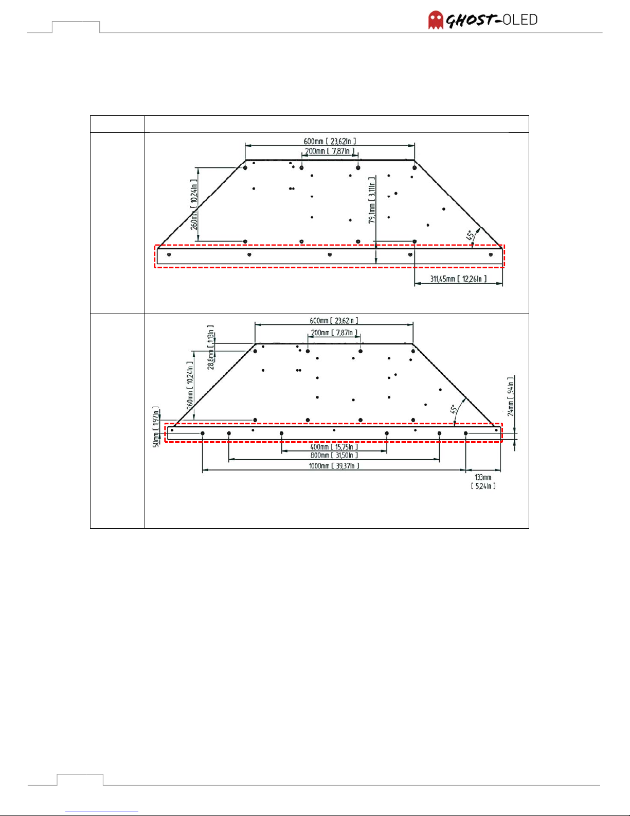
5.1.2 Screw hole pattern
Version Screw hole pattern in mm [In]
GhosT-
OLED-I
Note: The red marked area cannot be used.
GhosT-
OLED-PT
Note: The red marked area is only available in case of using the Table-Stand Version
Page 16
16
5.2 Installation possibilities
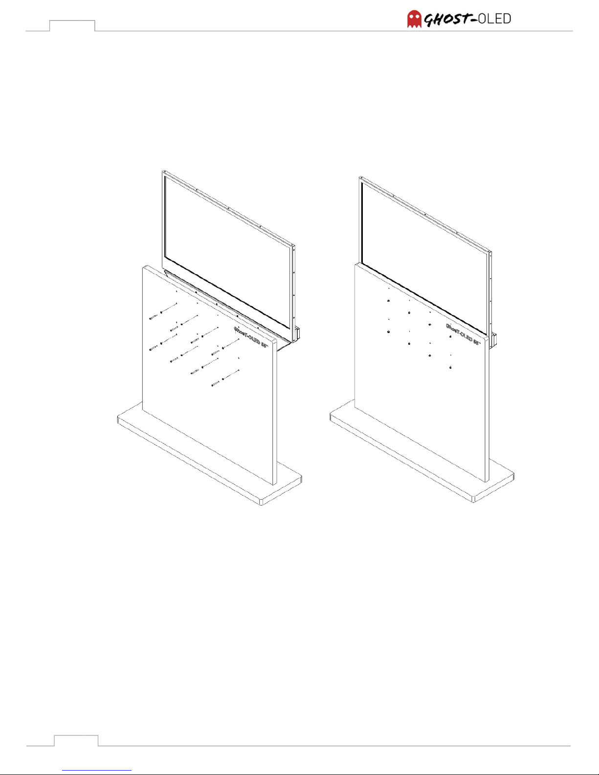
5.2.1 GhosT-OLED Table-Stand Version
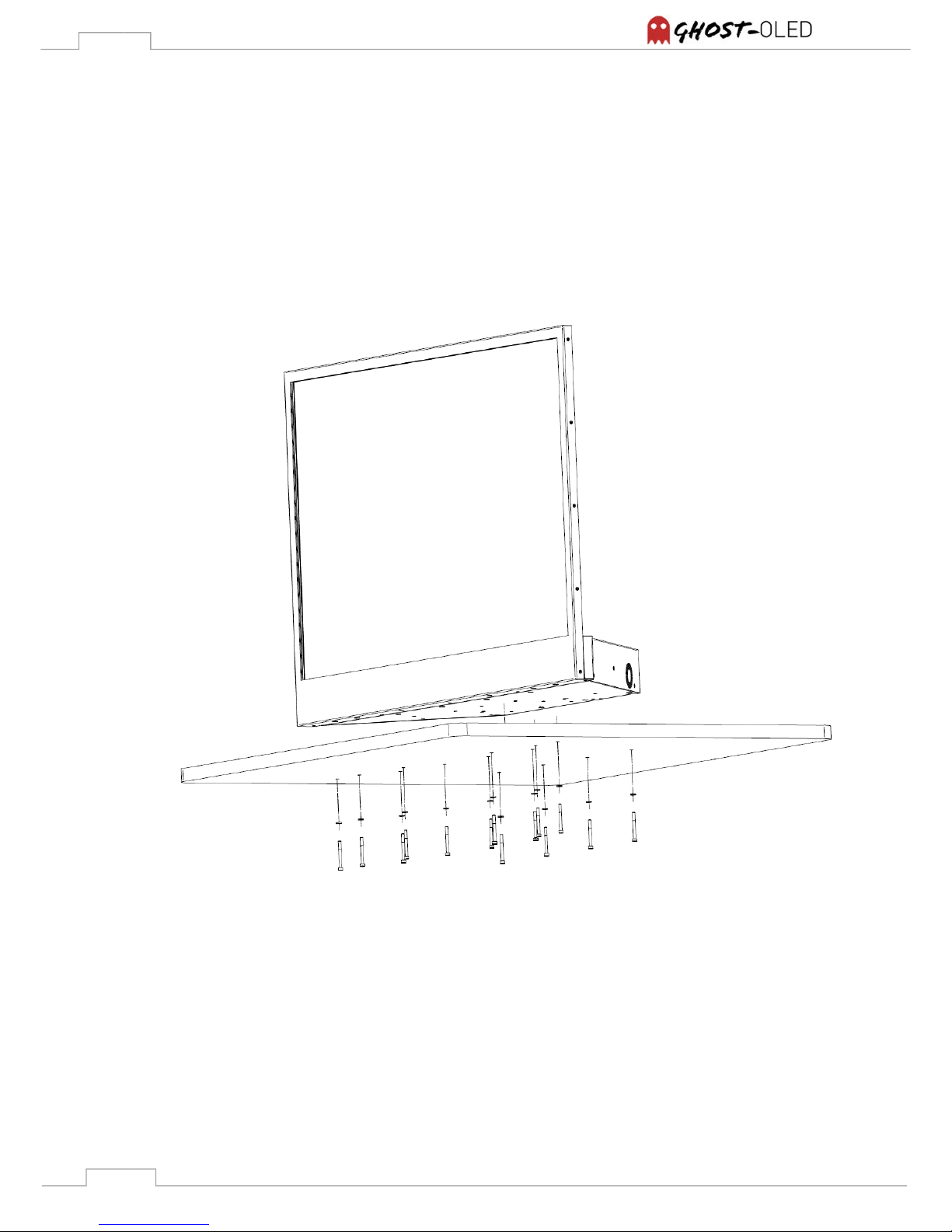
Set up on leveled surfaces, the GhosT-OLED TV option is able to run without additional mounting,
but it’s recommended to mount at least 4 screws to the exhibition furniture to hold the unit in place.
It’s also made for angled surfaces or portrait mode applications. Therefore the Table-Stand
Version provides min. 8 mounting points on the bottom side of the table foot. The length of the
screw depends on the surfaces thickness. Please refer to 5.1.1 Installations tools and material.
Figure 6: Installation example GhosT-OLED-PT TV Option
Page 17
17
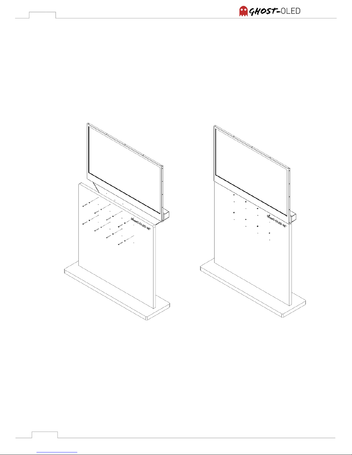
5.2.2 GhosT-OLED Straight Version
The GhosT-OLED Straight Version can only be mounted correctly by using all of the provided
mounting points. Therefore it’s required to work in a team of at least three persons. Two persons
are needed to align the display to the screw-hole pattern while the third person can insert the
screws into the mounting points.
Figure 7: Installation example GhosT-OLED-PT SV Option
Page 18
18
5.2.3 GhosT-OLED Straight Offset Version
The GhosT-OLED Straight Offset Version can only be mounted correctly by using all of the
provided mounting points. Therefore it’s required to work in a team of at least three persons. Two
persons are needed to align the display to the screw-hole pattern while the third person can insert
the screws into the mounting points. This version has the advantage that it’s possible to load the
weight to the angled mounting surface while installing.
Figure 8: Installation example GhosT-OLED-PT SOV Option
Page 19
19
6. Connector panel and control possibilities
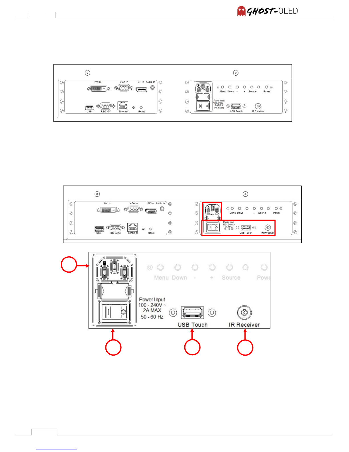
All versions share a similar connector panel on the backside of the table foot.
Figure 9: GhosT-OLED connector panel
6.1 Power Input, IR-Receiver and optional touch
These components are located at the lower right side of the connector panel like shown below:
a
b
c d
Page 20
20
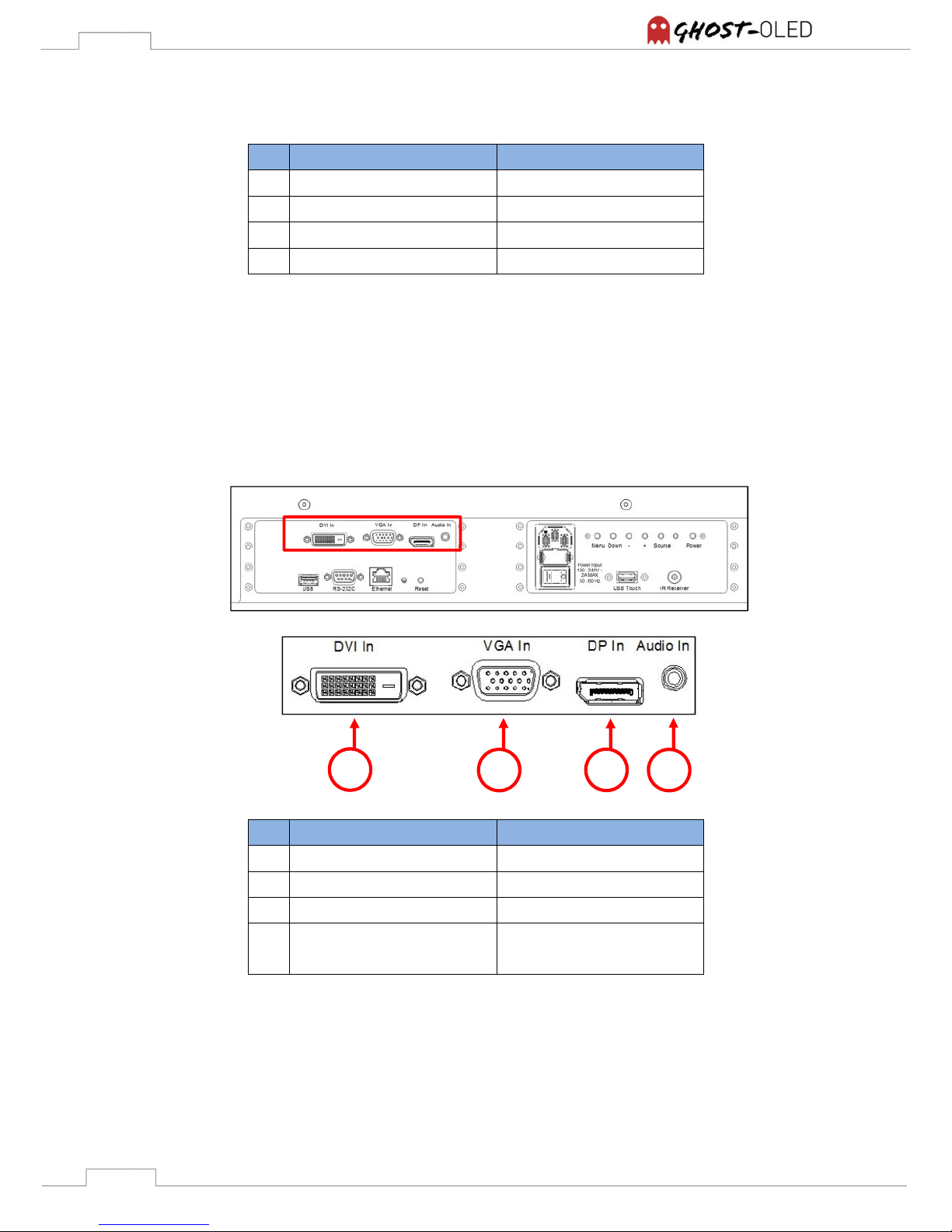
Description
technical design
a AC IN connector IEC socket
b Main Power switch 2 pin rocker switch
c primeTOUCH USB (optional) USB type A, female
d External IR-receiver input 3,5 mm jack, female
6.2 Video input connectors
The GhosT-OLED provides three different video input connectors. All of them are located at the
upper left side of the connector panel like shown below: The native input timing for the GhosT-
OLED series is 1920 by 1080 @60p. The display will accept other timings as well and most likely
display them, but the results might not by sufficient. The panel will always work with 60p refresh
rate even if the input frame rate might be different.
Description
technical design
a DVI connector DVI-D, female
b VGA IN Mini D-sub, 15 pin, female
c DISPLAYPORT connector DISPLAYPORT, female
d Audio input
Note: cannot be used
No function
a b c d
Page 21
21
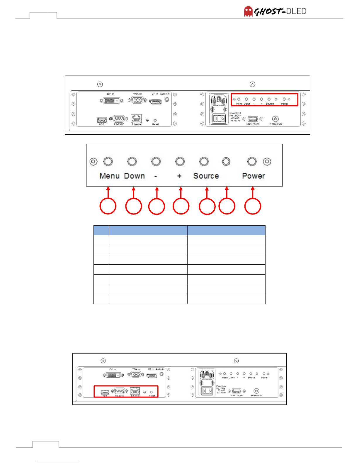
6.3 Local control
The GhosT-OLED series provides a user-friendly keyboard which is located at the upper right side
of the connector panel like shown below:
Description
technical design
a Menu button Short travel key switch
b Down button Short travel key switch
c Decrease button Short travel key switch
d Increase button Short travel key switch
e Source button Short travel key switch
f Status LED G/O/R, leaded LED
g Power button Short travel key switch
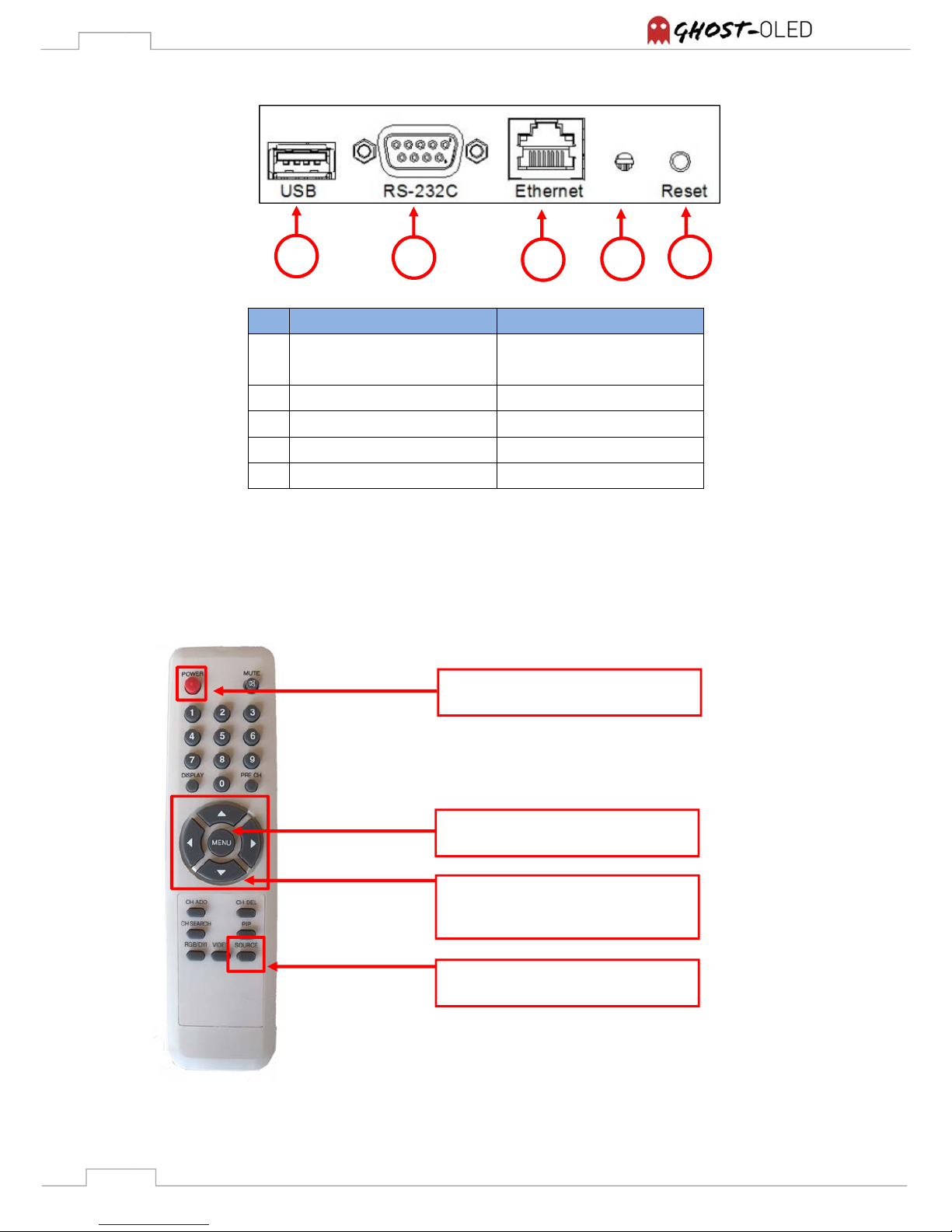
6.4 External Control Connectors
The GhosT-OLED series provides an option for external control that is located at the lower left
side of the connector panel like shown below:
a b c d e f
g
Page 22
22
Description
technical design
a USB connector
Note: for service access only
USB type A, female
b RS-232C connector D-sub, 9 pin, female
c LAN port RJ45, female
d Status LED G, leaded LED
e Reset Button Short travel key switch
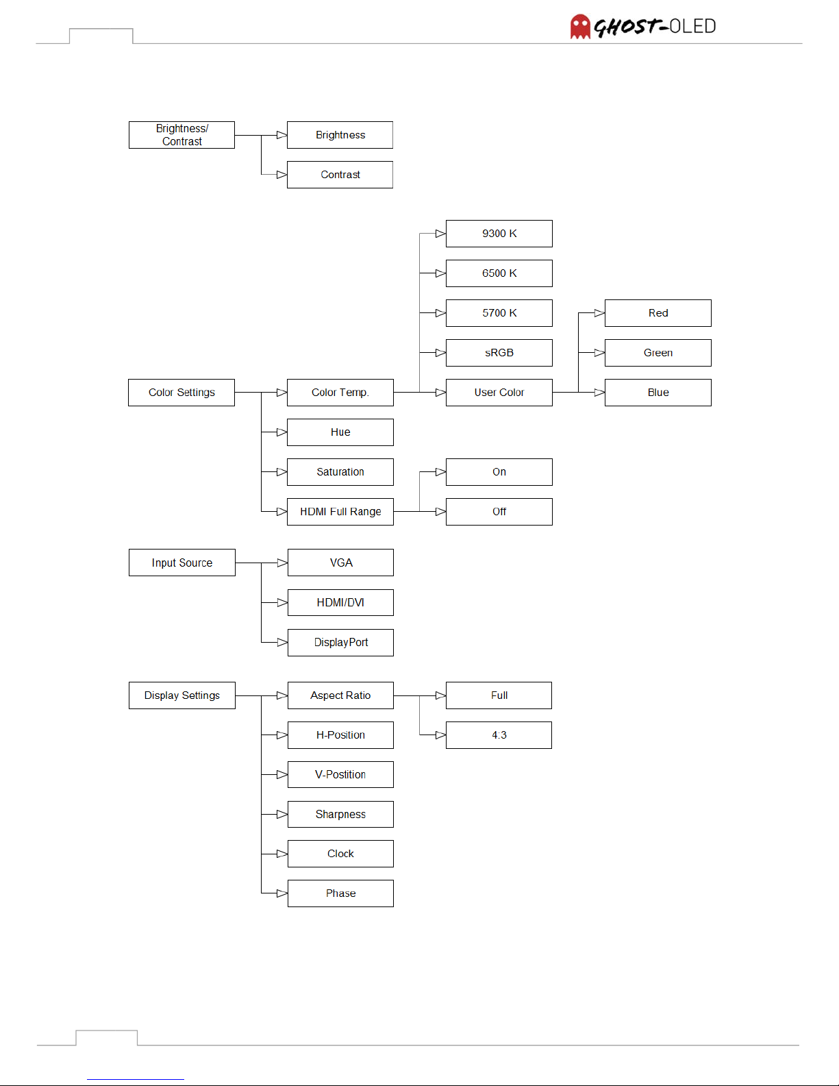
6.4.1 Remote control
All units are shipped including a remote control like described in 3 Scope of delivery. The
important functions that are required to set up a GhosT-OLED are explained below. All other
buttons have no function.
1
Power button
Turns display on and off
Arrow keys
For moving up, right, down and left
in the menu
Menu Button
Opens the menu
Source button
Direct link to choose source option
a b c d e
Page 23
23
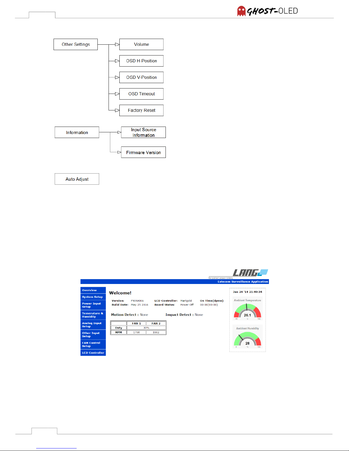
6.4.2 On-Screen-Display (OSD) menu guide
Page 24
24
6.4.3 Web interface
All displays of GhosT-OLED series can be controlled by an easy operable web interface which
provides several capturing and controlling options.
The picture below shows the welcome screen which allows you to read off ambient parameters
and current fan values.
Figure 10: Web interface - welcome screen
Note: These menu items are not adjustable
Note: This function is only activated when using VGA
Page 25
25
7. primeTOUCH option
As HID (human interface device) the primeTOUCH is a plug and play capable system. For
advanced features like calibrating the touch coordinates to the image or running a diagnose of the
system you need to install a special software. It is called “Multi Touch Platform” and it is provided
on an USB stick that comes with every GhosT-OLED unit. Besides that the USB stick contains a
detailed manual for the primeTOUCH function and additional documentation. The software and
documentation can also be downloaded from www.prime-touch.com.
Note: It’s necessary to run a calibration process every time you connect the GhosT-OLED-PT
with a new PC or Mac.
8. Content Guide
8.1 Pixel Shift
The GhosT-OLED is running with an integrated pixel shift to avoid image retention. This function
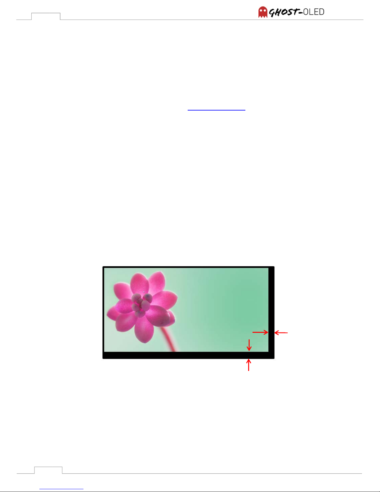
shifts the shown image spirally in intervals of 30 seconds. The maximum offset during shifting
image is about 16 pixels. This leads to the fact that content will partly be shifted out of the active
screen area and not be shown. Also there will be parts of the active screen area that will not show
content. In case of using the T-OLED together with a touch input device, calibration will not remain
precise all the time.
Figure 11: Pixel shift maximum
It is possible to deactivate the pixel shift function in the menu. Please refer to 6.4.2 On-Screen-
Display (OSD) menu guide.
Note: It its highly recommended to activate the Pixel shift. Deactivating the pixel shift function
can cause permanent burn in effects in the panel. Deactivate only in controlled
environments where the content can’t be switched to static.
16 pixels
16 pixels
Page 26
26
Note: If you are designing interactive content consider the pixel shift functionality. For example
buttons should have an adequate size.
8.2 Transparency
Black colored content parts will appear transparent so it’s recommended to provide as much black
parts as possible during content design to highlight the panel transparency. Such content will also
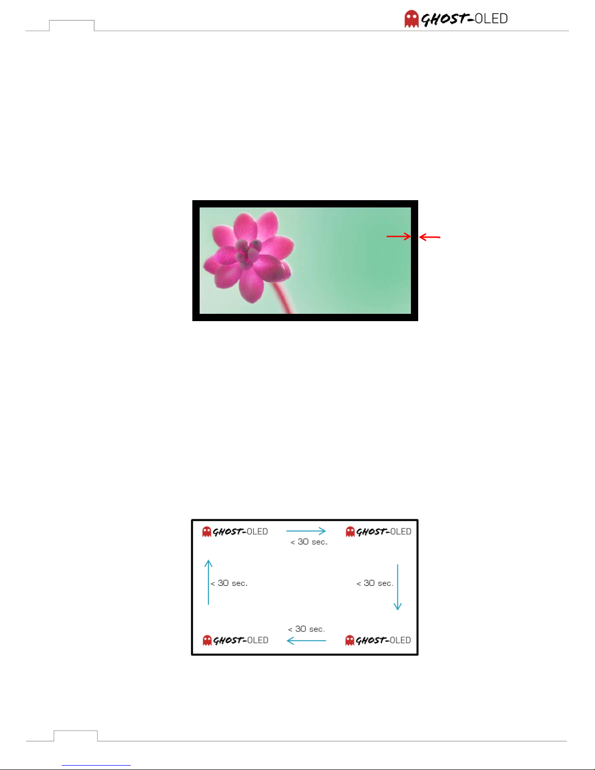
minimize image retention. To conceal the pixel shift it is recommended to have more than 16 black
pixels on the image boarder. (Figure 12)
Figure 12: Content + 16 black pixel border
8.3 Static content
Moving content is more suitable than static content. If static images are necessary it’s
recommended to display moving images between the static images. Furthermore static images
should not be displayed more than 30 seconds because this can cause image retention and a
reduction of lifetime.
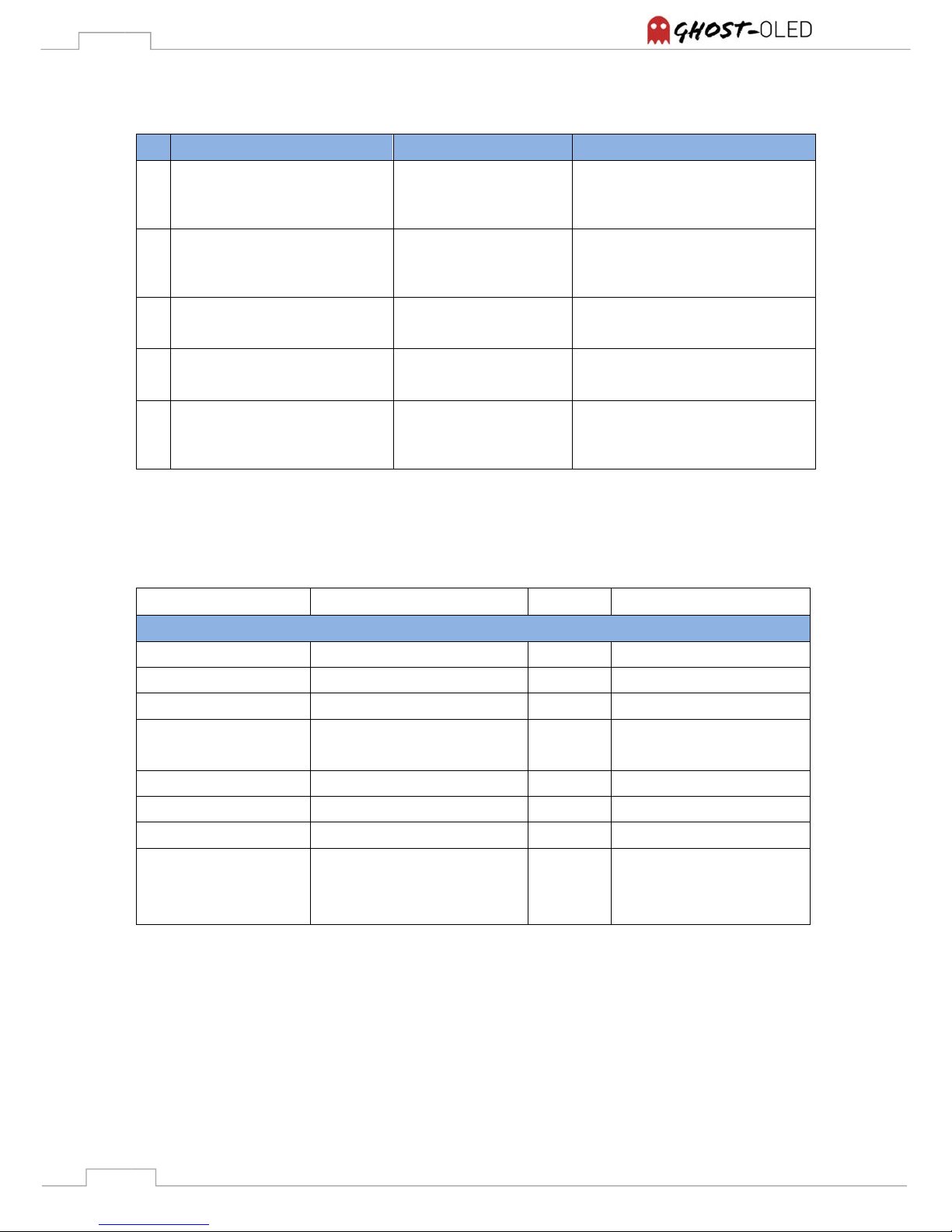
Logos or letterings embedded to your content must also not be displayed more than 30 sec even if
the remaining content is moving. If such logos or letterings are necessary it’s recommended to
rotate them in intervals smaller than 30 seconds as well. (Figure 13)
Figure 13: Rotation of logos or letterings
16 pixels
Page 27
27
9. Troubleshooting
Description of error
Potential cause
Potential solutions
1 No picture is shown
- Power is turned of
- Faulty cables or
adapters
-
Wrong source
- Check power switch
- Check cabling and adapters
- Check if correct source is chosen
2 Picture disappears periodically
after a few seconds
- Display is rebooting
periodically
- Check power supply, mains
adaptor could be damaged
- Check image signal, resolution
may change periodically
3 Beeping noise sounds
- Fan is blocked
-
Check fans, one of them might
be blocked
4 No touch function
- Faulty USB cable
- Faulty USB extension
- Check cabling
- Check if passive USB extender is
too large or damaged
5 False touch function
- Driver is not installed
- Not calibrated
- Check if driver is installed
correctly
- Calibrate device (refer to 7
primeTOUCH option)
Please contact support if none of the solutions is working: [email protected]
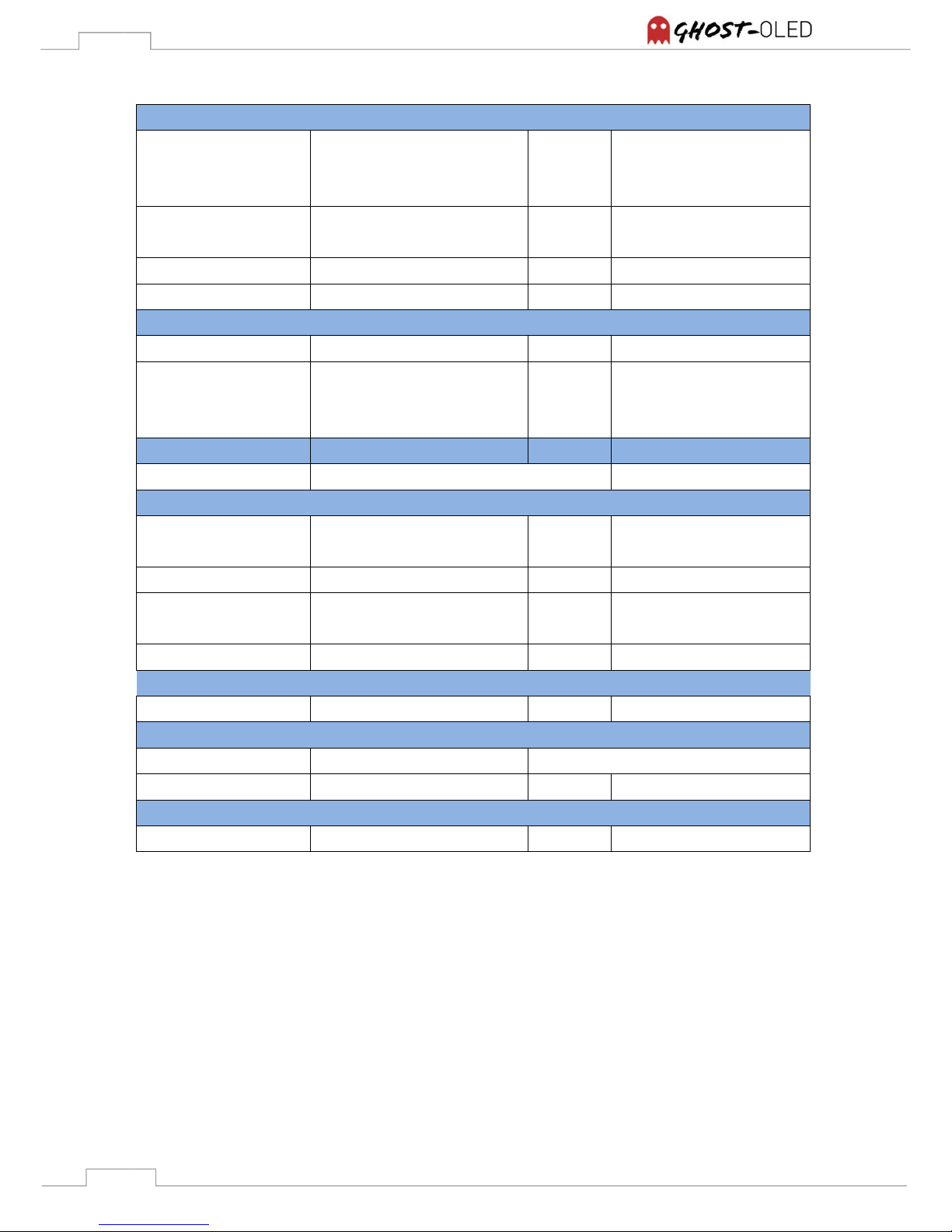
10. Specifications
Item
Specification
Unit Note
Display
Resolution
1920 x 1080 Pixel
Aspect R
atio
16/9
Display A
rea
1209.6 x 680.4 [Diagonal: 55’’] mm [inch]
Luminance of W
hite
Peak 1%: 500
Full White: 150
cd/m²
Typical (1)
Transmittance
45% Typical (1)
Display Colours
1,07Billion
Orientation
Landscape/Portrait
Options
Table Version (by default)
Straight Version (2)
Straight Offset Version (2)
Page 28
28
Connectivity
and C
ontrol
Input
1 x DisplayPort
1 x DVI-D
1 x VGA
(Digital)
(Digital)
(Analog)
External Control
Ethernet (Web Interface)
RS-232C
Remote Control
IR Remote With external IR receiver
Local Control
Keyboard On back side
Physical Specification
Dimensions
mm
See: 11. Product outlines
Weight
GhosT-OLED-I
GhosT-OLED-PT
42
35
kg
Electrical
Power Consumption
100 - 240 V~ / 2A MAX / 50 - 60 Hz
Environmental Conditions
Storage T
emperature
Min: 5
Max: 40
°C
Operating Temp.
Normal: 25 +/- 10 °C
Storage H
umidity
Min: 35
Max: 75
%rH
Operating H
umidity
Normal: 55 +/- 20 %rH
Lifetime
Operating Lifetime
30.000 Hour (3)
primeTOUCH Options
Touch
Points
6 / 12 / 32 / 50 Simultaneous touch points
Connection
USB A Female
Certifications
Product A
pprovals
CE / FCC
Note (1) might vary depending on front glass
Note (2) on request
Note (3) Operating Lifetime is defined as the time until the brightness is reduced to 50% of its original
value and can only be guaranteed under recommended operating conditions.
Page 29
29
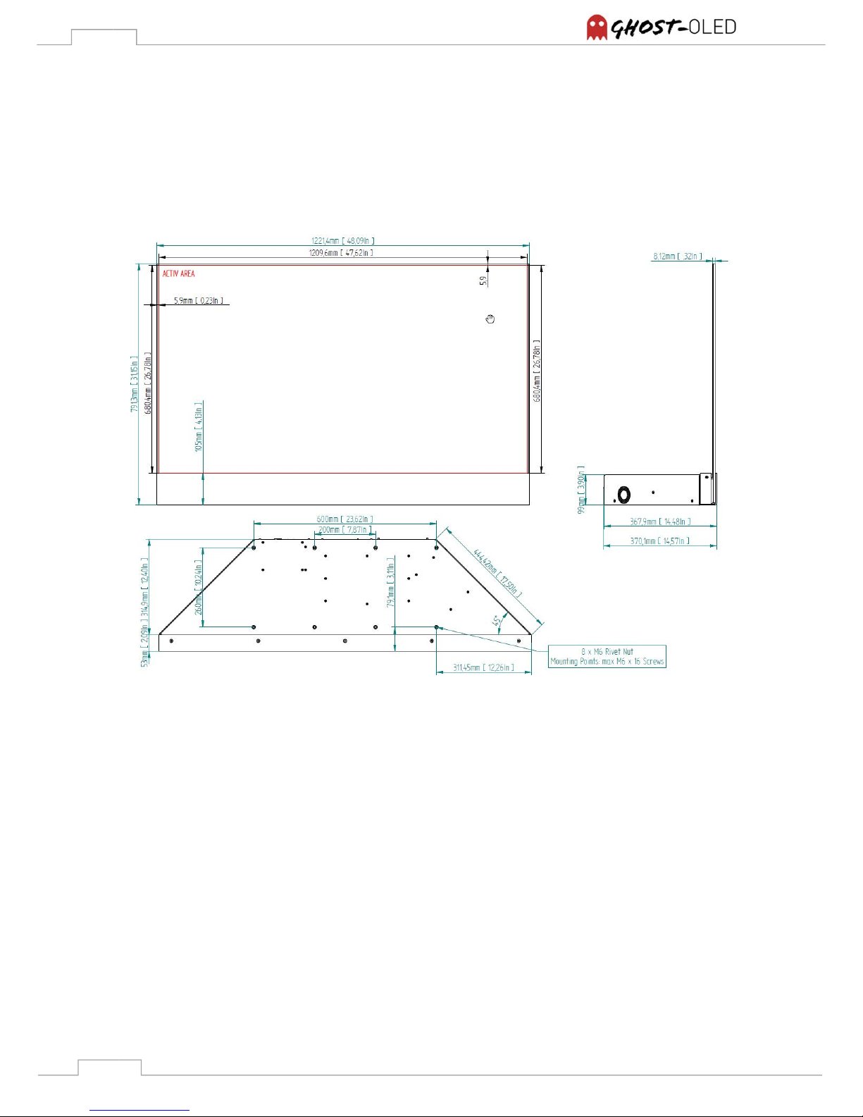
11. Product outlines
11.1 Drawings GhosT-OLED-I
11.1.1 Table-Stand Version
Figure 14: GhosT-OLED-I TV Option, front, side, bottom view
Page 30
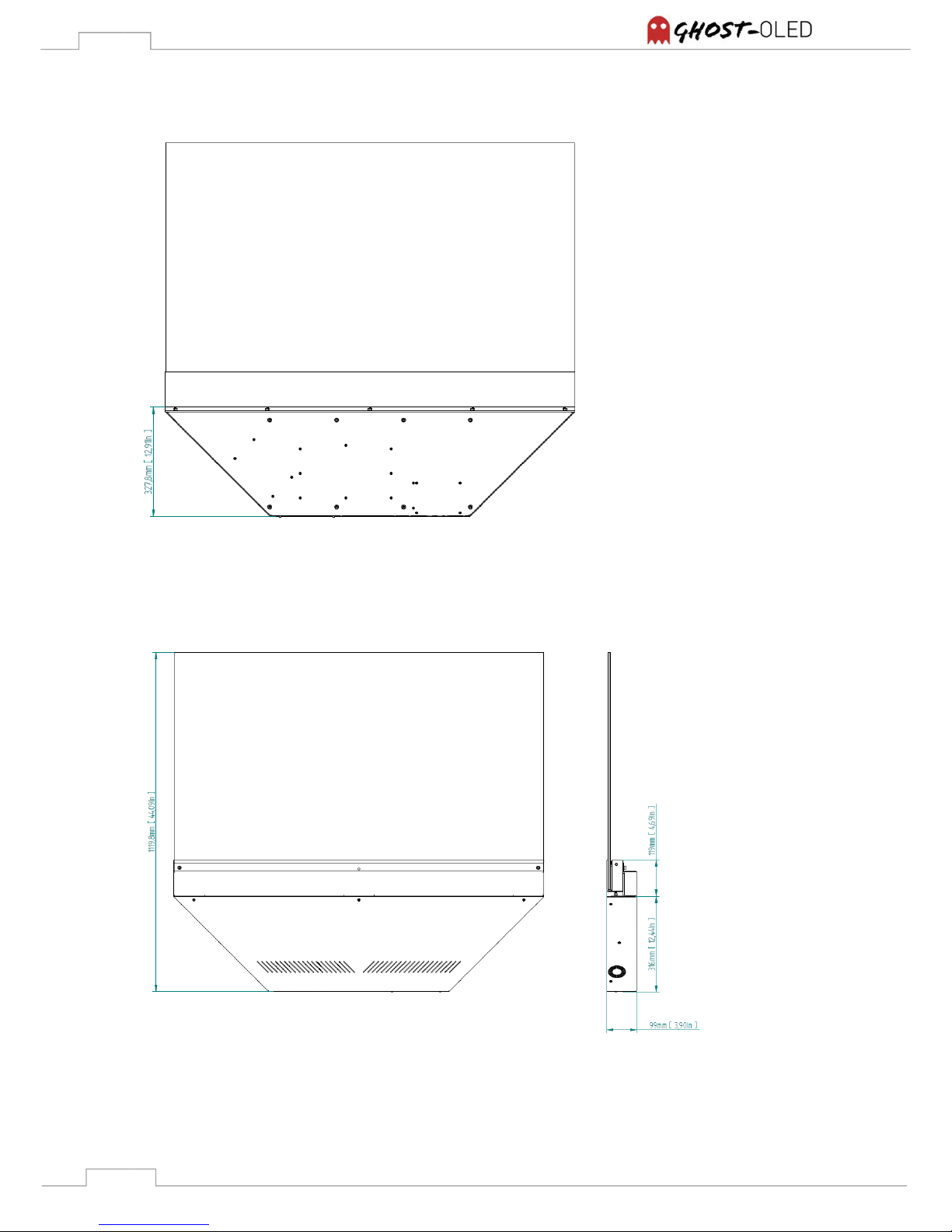
30
11.1.2 Straight Version
Figure 15: GhosT-OLED-I SV Option, front view
Figure 16: GhosT-OLED-I SV Option, back, side view
Page 31
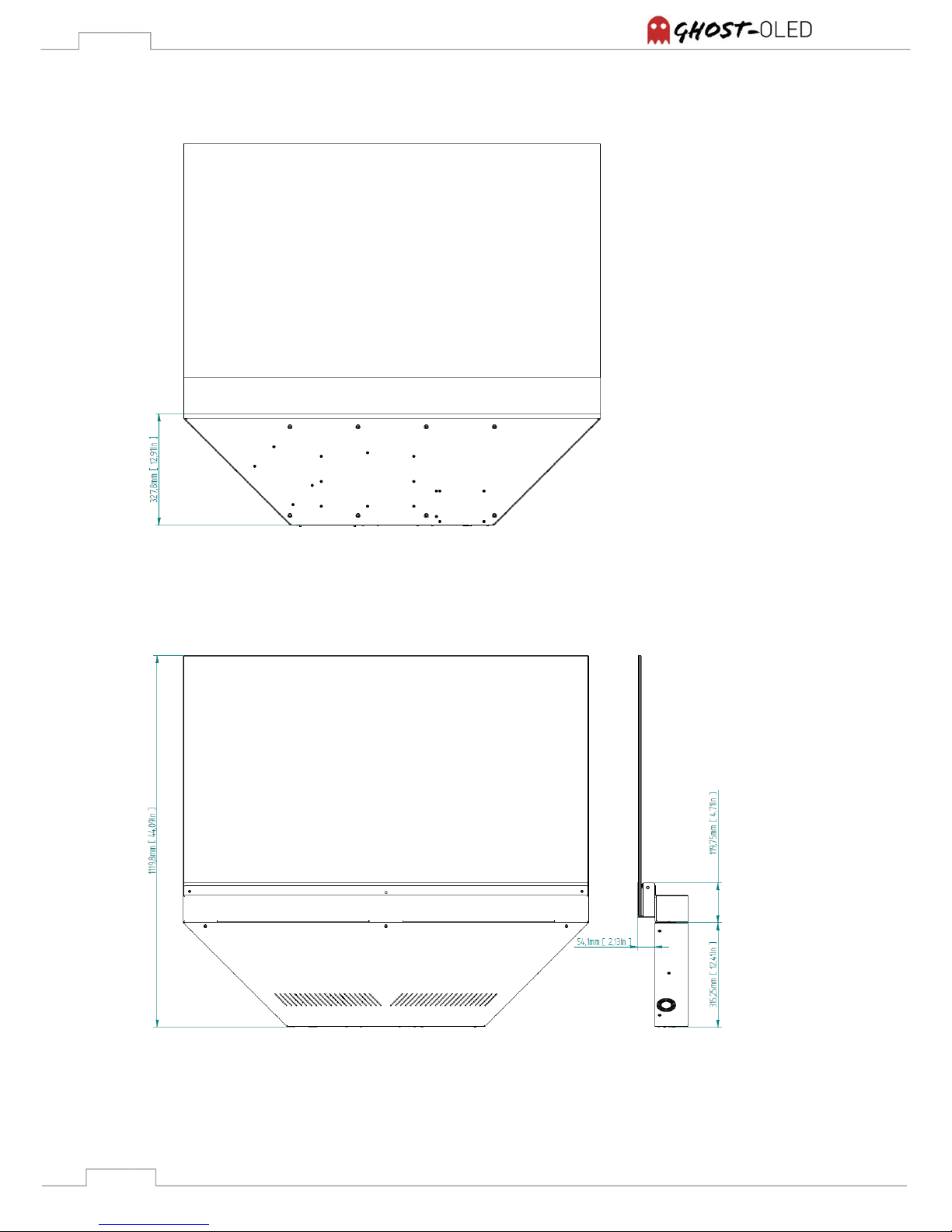
31
11.1.3 Straight Offset Version
Figure 17: GhosT-OLED-I SOV Option, front view
Figure 18: GhosT-OLED-I SOV Option, back, side view
Page 32
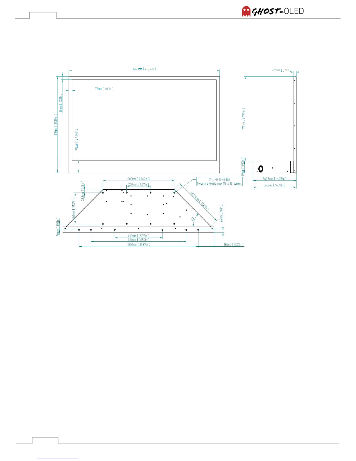
32
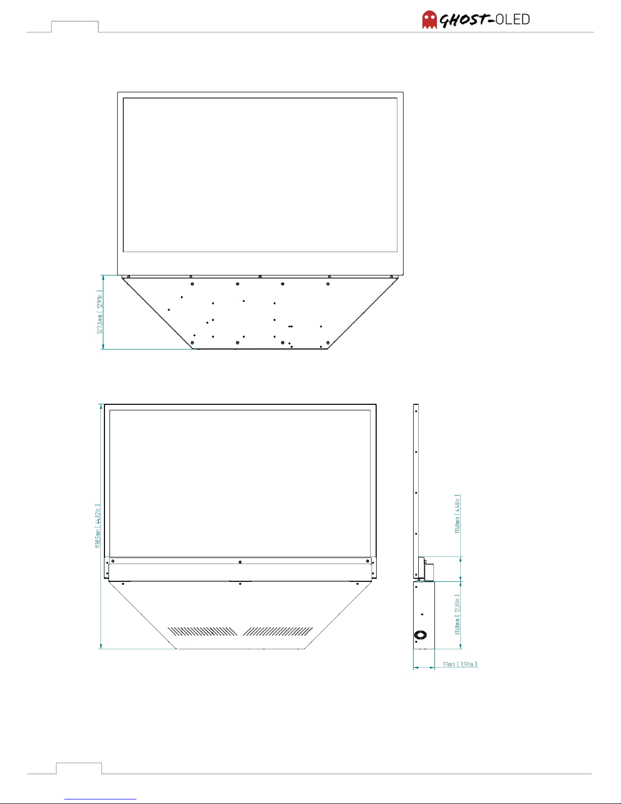
11.2 Drawings GhosT-OLED-PT
11.2.1 Table-Stand Version
Figure 19: GhosT-OLED-PT TV Option front, side, bottom view
Page 33
33
11.2.2 Straight Version
Figure 20: GhosT-OLED-PT SV Option front view
Figure 21: GhosT-OLED-PT SV Option back, side view
Page 34
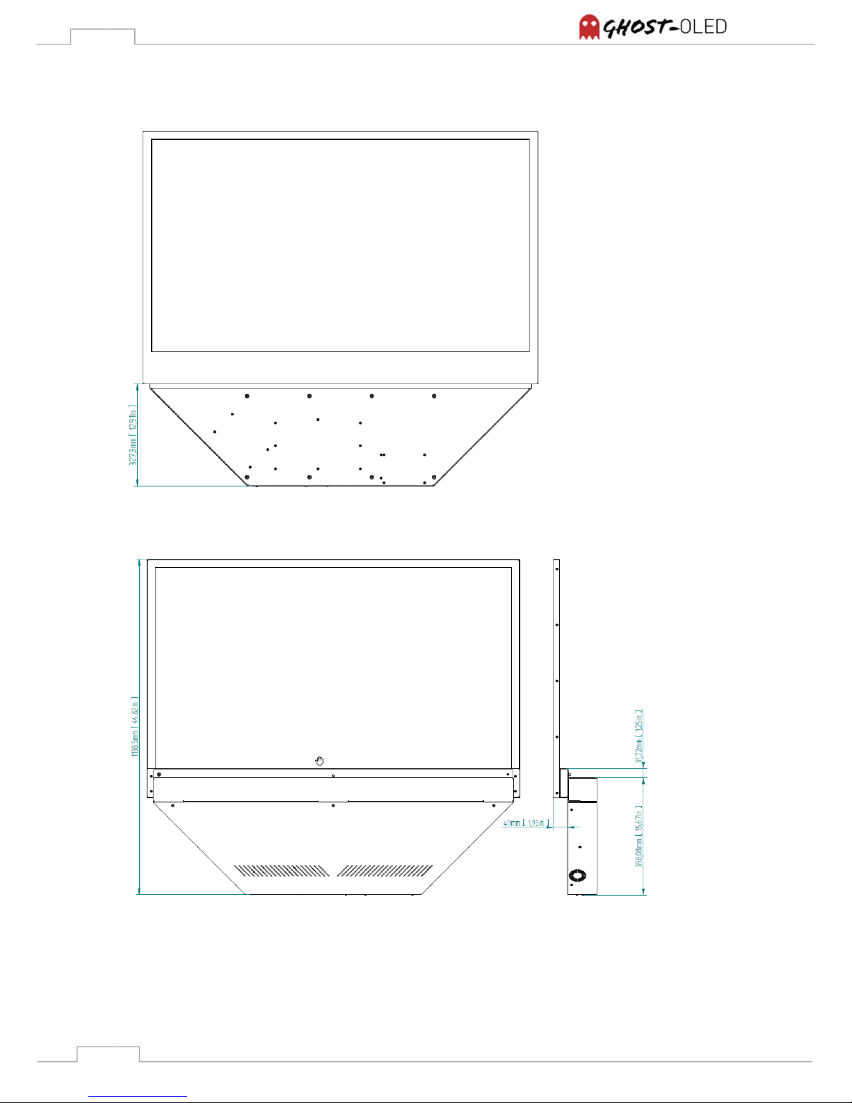
34
11.2.3 Straight Offset Version
Figure 22: GhosT-OLED-PT SOV Option front view
Figure 23: GhosT-OLED-PT SOV Option back, side view
Page 35
35
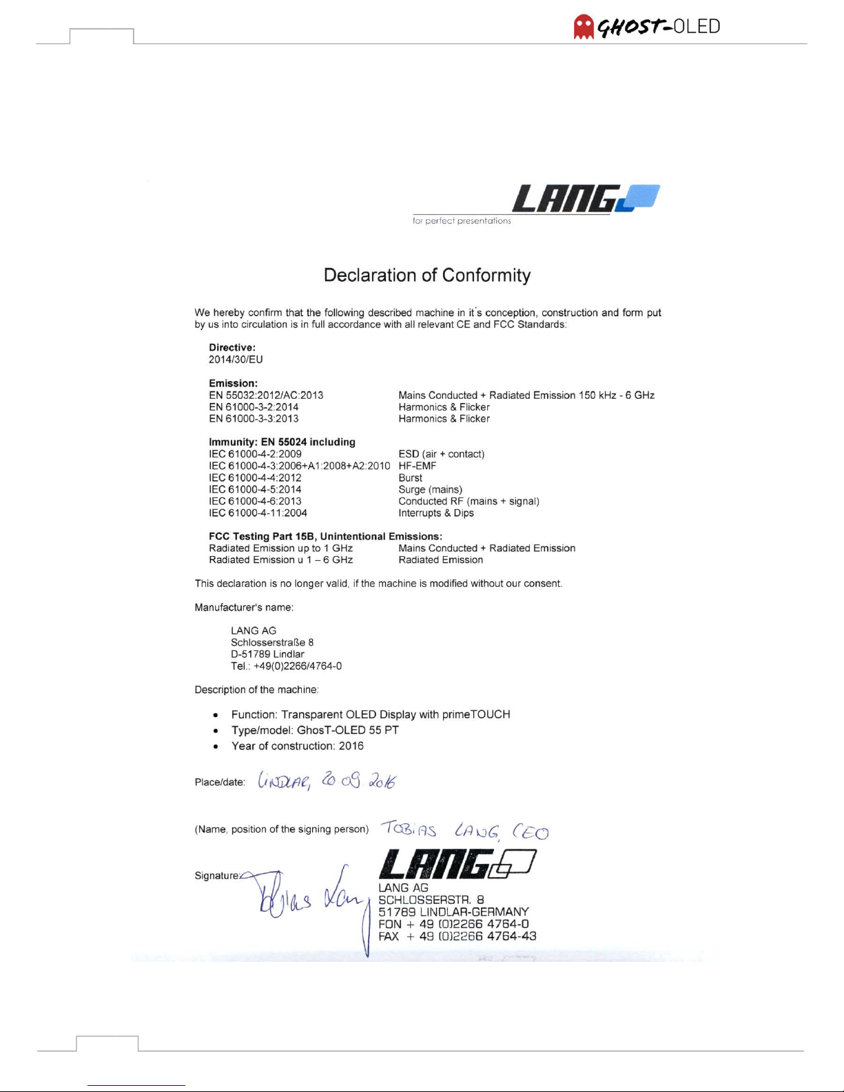
12. Certification
Page 36
36
Made in Germany
by
www.lang-ag.com
Schlosserstraße 8
51789 Lindlar
Germany
09/16
 Loading...