

Page 1
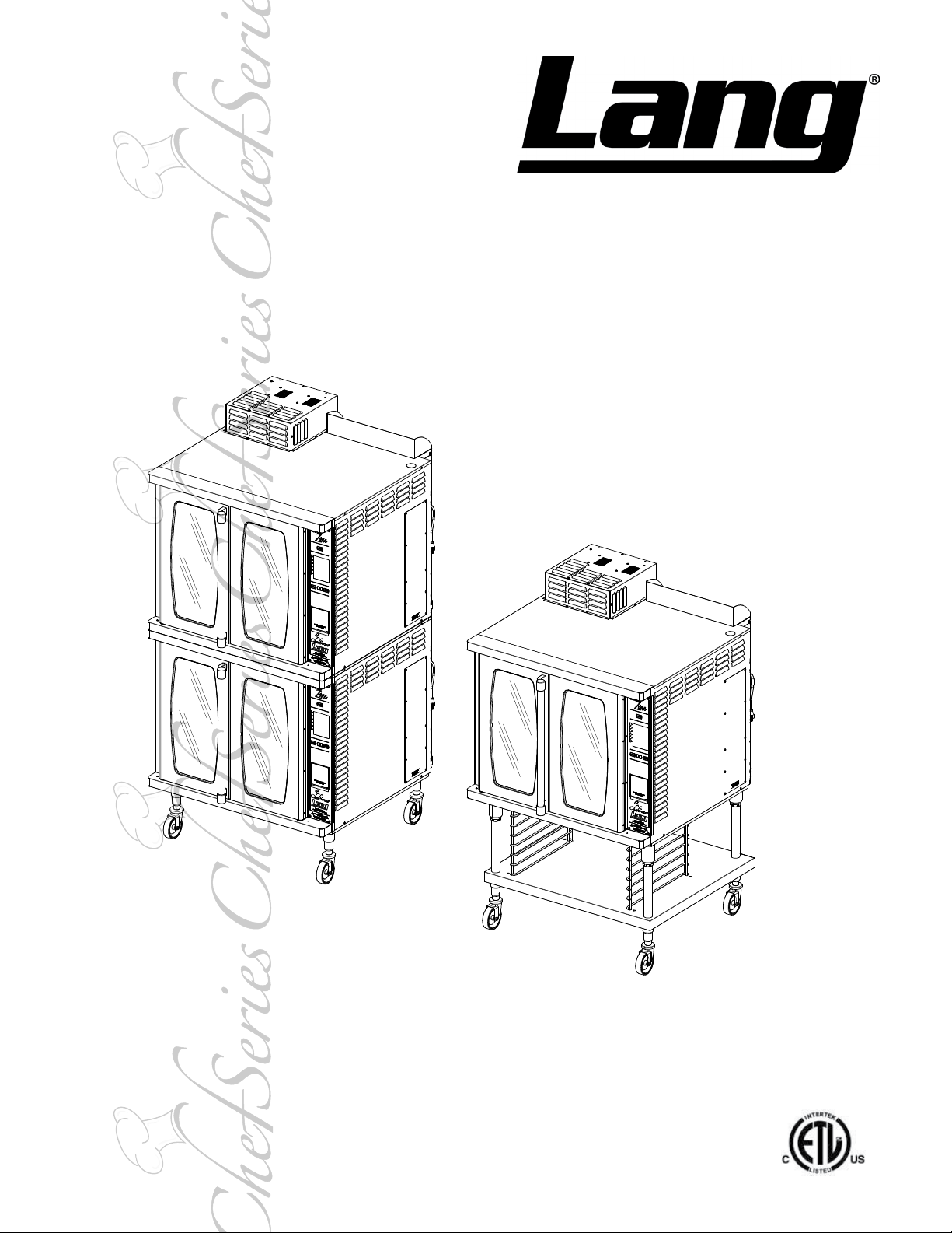
GAS FULL SIZE
COMPUTERIZED
CONVECTION OVEN
GCSF-ES
GCSF-EZ
Installation and
Operation
Instructions
2M-W741 Rev. D 11/11/13
GCSF_2
GCSF_1
Page 2
SAFETY SYMBOL
DO NOT STORE OR USE GASOLINE OR OTHER FLAMMABLE VAPORS AND LIQUIDS IN
The installation of the Appliance must conform to the NATIONAL FUEL GAS CODE "ANSI Z223.1 - LATEST
EDITION" AND ALL LOCAL GAS COMPANY RULES AND REGULATIONS.
IN CANADA INSTALLATION SHALL BE IN ACCORDANCE WITH THE CURRENT CAN/CGA-B149.1 NATURAL
GAS INSTALLATION CODE OR CAN/CGA-B149.2 PROPANE INSTALLATION CODE AND LOCAL CODES WHERE
APPLICABLE.
INSTRUCTIONS TO BE FOLLOWED IN THE EVENT USER SMELLS GAS. THIS INFORMATION
SHALL BE OBTAINED BY CONSULTING YOUR LOCAL GAS SUPPLIER. AS A MINIMUM, TURN
OFF THE GAS AND CALL YOUR GAS COMPANY AND YOUR AUTHORIZED SERVICE AGENT.
IMPROPER INSTALLATION, ADJUSTMENT, ALTERATION, SERVICE OR MAINTENANCE CAN
CAUSE PROPERTY DAMAGE, INJURY OR DEATH. READ THE INSTALLATION, OPERATION
& MAINTENANCE INSTRUCTIONS THOROUGHLY BEFORE INSTALLING OR SERVICING THIS
These symbols are intended to alert the user to the presence of important operating
and maintenance instructions in the manual accompanying the appliance.
FOR YOUR SAFTEY
THE VICINTIY OF THIS OR ANY OTHER APPLIANCE.
POST IN PROMINENT LOCATION
EVACUATE ALL PERSONNEL FROM THE AREA.
WARNING
EQUIPMENT.
WARNING
RISK OF FIRE OR ELECTRIC SHOCK
DO NOT OPEN
WARNING, TO REDUCE THE RISK OF ELECTRICAL SHOCK, DO NOT REMOVE
CONTROL PANEL. NO USER-SERVICABLE PARTS INSIDE.
REPAIRS SHOULD BE DONE BY AUTHORIZED SERVICE PERSONNEL ONLY.
NOTICE
Using any part other than genuine Lang factory supplied parts relieves the manufacturer of all liability.
Lang reserves the right to change speci cations and product design without notice. Such
revisions do not entitle the buyer to corresponding changes, improvements, additions or
replacements for previously purchased equipment.
Due to periodic changes in designs, methods, procedures, policies and regulations, the
specifications contained in this sheet are subject to change without notice. While Lang
Manufacturing exercises good faith efforts to provide information that is accurate, we are
not responsible for errors or omissions in information provided or conclusions reached as a
result of using the speci cations. By using the information provided, the user assumes all risks in con-
nection with such use.
MAINTENANCE AND REPAIRS
Contact your local dealer for service or required maintenance. Please record the model number, serial
number, voltage and purchase & Installation Information in the area below and have it ready when you
call to ensure a faster service.
2M-W741 Gas Full Size Computerized Convection Oven GCSF
Model No.:
Serial No.:
Voltage:
1-Phase or 3 Phase:
Purchased From:
Location:
Purchase Date:
Installed Date:
2
Page 3
PROBLEMS, QUESTIONS or CONCERNS
Before you proceed consult you authorized Lang service agent directory
or
Call the Lang Technical Service at 314-678-6315.
SPECIFICATIONS
Model Height x Width x Depth
GCSF_1
GCSF_2
Model Voltage Hz Total kW Ph.
GCSF_1
GCSF_2 1.4 3 11.6 3/8” NPT, 120,000 BTU/hr
(91.4cm x 101.6cm x 101.6cm) (252 kg) (281 kg)
(188cm x 102.6cm x 101.6cm) (503 kg) (562 kg)
120V 60
36” x 40” x 40”
74” x 40.4” x 40”
0.7 1 5.8` 3/8” NPT, 60,000 BTU/hr
Clearance from combustible
surface
Side:0, Back: 1, Floor: 4
Side:0, Back: 1, Floor: 4
UTILITY REQUIREMENTS
Amps/
Line
Total Gas Req.
Weight
Installed Shipping
555 lbs. 620lbs
1110 lbs. 1240 lbs
Gas W.C. Max.
Nat LP
4” W.C. 9” W.C. 14” W.C.
Freight
Class
70
70
Incoming Gas
Pressure
2M-W741 Gas Full Size Computerized Convection Oven GCSF
WATER QUALITY REQUIREMENTS
Waterline pressure and quality MUST meet Lang Manufacturing Specications listed below.
Contact your local water equipment system provider to assist you in determining your
specic water quality, or contact Lang Technical support for assistance, 1-800-807-9054.
-IMPORTANT-
YOUR LOCAL WATER CONDITIONS MAY DAMAGE YOUR LANG EQUIPMENT.
FAILURE TO PROPERLY TREAT WATER MAY RESULT IN DAMAGE AND MAY VOID
SOME OR ALL OF THE WARRANTY.
WATER SPECIFICATIONS, after treatment the water must continuously be within the
following parameters.
Cold Water: 20 to 80 PSI, 3 GPH minimum capacity
pH: 6.8 to 7.6
Conductivity: <1/500,000 ohms per inch
Total dissolved solids: < 100 PPM
Hardness: 2 to 4 grains per gallon
Maximum Salinity Ion Content
• Chlorine: < 0.5 PPM
• Chlorides: < 30 PPM
• Sulfates: < 40 PPM
• Iron: < 0.1 PPM
• Copper: < 0.05 PPM
• Manganese: < 0.05 PPM
• Chloramines: < 0.5 PPM
3
Page 4
THIS APPLIANCE MUST BE GROUNDED AT THE TERMINAL PROVIDED. FAILURE TO
GROUND THE APPLIANCE COULD RESULT IN ELECTROCUTION AND DEATH.
WARNING
NOTICE
NOTICE
NOTICE
CAUTION
INSTALLATION OF THE UNIT MUST BE DONE BY PERSONNEL QUALIFIED TO WORK
WITH ELECTRICITY AND PLUMBING. IMPROPER INSTALLATION CAN CAUSE
INJURY TO PERSONNEL AND/OR DAMAGE TO EQUIPMENT. UNIT MUST BE
INSTALLED IN ACCORDANCE WITH ALL APPLICABLE CODES.
The data plate is located on the lower right side panel of the unit. The oven voltage,
wattage, serial number, and clearance specications are on the data plate. This
information should be carefully read and understood before proceeding with the
installation.
The installation of this unit must conform to applicable national, state and locally
recognized installation standards.
The installation of any components such as a vent hood, grease extractors, re
extinguisher systems, must conform to their applicable National, State and locally
recognized installation standards.
MOST CLEANERS ARE HARMFUL TO THE SKIN, EYES, MUCOUS MEMBRANES AND
CLOTHING. PRECAUTIONS SHOULD BE TAKEN TO WEAR RUBBER GLOVES,
GOGGLES OR FACE SHIELD AND PROTECTIVE CLOTHING. CAREFULLY READ THE
WARNING AND FOLLOW THE DIRECTIONS OF THE LABEL OF THE CLEANER TO BE
USED.
KEEP WATER AND SOLUTIONS OUT OF CONTROLS. NEVER SPRAY OR HOSE
CONTROL CONSOLE, ELECTRICAL CONNECTIONS, ETC.
WARNING
WARNING
NOTICE
NOTICE
BOTH HIGH AND LOW VOLTAGES ARE PRESENT INSIDE THE APPLIANCE WHEN
THE UNIT IS PLUGGED/WIRED INTO A LIVE RECEPTACLE. BEFORE REPLACING
ANY PARTS, DISCONNECT THE UNIT FROM THE ELECTRIC POWER SUPPLY.
The appliance is equipped with a 3-prong (grounded) plug for your protection
against shock hazard and must be plugged directly into a properly grounded 3-prong
receptacle. DO NOT cut or remove this gronding prong from the plug.
Never use chlorine sanitizer in contact with stainless steel surfaces longer than 10
minutes. Longer contact can cause corrosion.
Service this, or any other Lang appliance must be performed by qualied personnel
only. Consult your authorized service station directory or call the factory at
314-678-6315, or log onto www.langworld.com for the service agent nearest you.
2M-W741 Gas Full Size Computerized Convection Oven GCSF
4
Page 5

CAUTION
GENERAL INFORMATION
This equipment is designed and sold for commercial use only by personnel trained and
experienced in its operation and is not sold for consumer use in and around the home nor for
use directly by the general public in food service locations.
Before using your new equipment, read and understand all the instructions & labels associated
with the unit prior to putting it into operation. Make sure all people associated with its use
understand the units operation & safety before they use the unit.
All shipping containers should be checked for freight damage both visible and concealed.
This unit has been tested and carefully packaged to insure delivery of your unit in perfect
condition. If equipment is received in damaged condition, either apparent or concealed, a claim
must be made with the delivering carrier.
Concealed damage or loss - if damage or loss is not apparent until after equipment is unpacked,
a request for inspection of concealed damage must be made with carrier within 15 days. Be
certain to retain all contents plus external and internal packaging materials for inspection. The
carrier will make an inspection and will supply necessary claim forms.
PURCHASER’S RESPONSIBILITY
It is the responsibility of the purchaser:
1. To see that the electric & gas services (12” WC max) for the oven are installed on site in
accordance with the manufacturer’s specications.
2. To unload, uncrate, and install the oven in its proper location and in accordance with this
installation operation manual.
3. To see that electric services are connected properly by a qualied installer of your
choice.
4. To see that there is a water purication system supplying the oven that meets Lang
Manufacturing Specications. All connections must be in accordance with applicable code
requirements.
5. To arrange for inspection and operation check-out by an authorized service technician.
2M-W741 Gas Full Size Computerized Convection Oven GCSF
5
Page 6
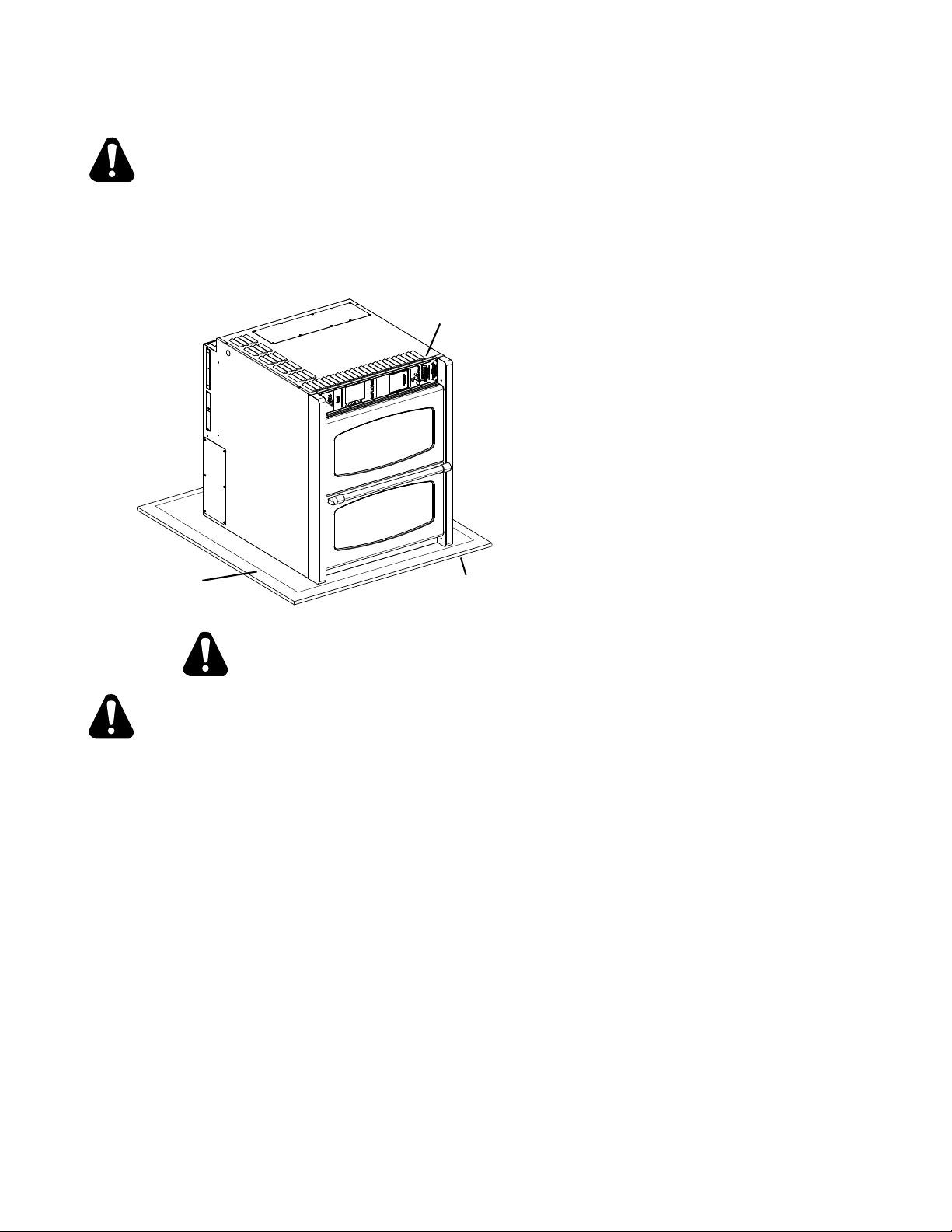
CAUTION
Cardboard
Micro-foam
UNCRATING
The oven will arrive completely assembled inside a wood frame. Prior to uncrating move the
oven as close to its nal location as practical. This will protect it from damage associated with
moving (scratches, dings, dropping).
Some hardware, (i.e. casters, legs, stacking kits) may be shipped inside the oven.
Please remove any items before continuing.
It may be necessary during the installation to place the unit on its side (i.e. leg, caster installation,
t through doors, etc) follow these guidelines to lessen the risk of damage to the unit.
Control
Panel
Placing the unit onto its side:
1. Have oven completely uncrated and sitting
on its shipping crate.
2. When using a dolly, place a piece of plywood
on top of the dolly to distribute the weight
evenly. Also have a piece of cardboard or
micro-foam between plywood and oven to
protect the nish from scratches.
3. Carefully tilt the oven onto its LEFT SIDE
ONLY (or CONTROL SIDE UP)
IL1214
NOTE: Turning the unit onto its right side
will damage the control panel.
4. Avoid sudden drops.
or
Plywood
CAUTION
NEVER lay oven with the control side down, this will damage the controls.
THE OVEN WEIGHS 525 LBS (238KG). FOR SAFE HANDLING, INSTALLER SHOULD
OBTAIN HELP AS NEEDED, OR EMPLOY APPROPRIATE MATERIALS HANDLING
EQUIPMENT (SUCH AS A FORKLIFT, DOLLY, OR PALLET JACK) TO REMOVE THE UNIT
FROM THE SKID AND MOVE IT TO THE PLACE OF INSTALLATION.
ANY STAND COUNTER OR OTHER DEVICE ON WHICH THE OVEN WILL BE LOCATED
MUST BE DESIGNED TO SUPPORT THE WEIGHT OF THE OVEN.
SHIPPING STRAPS ARE UNDER TENSION AND CAN SNAP BACK WHEN CUT.
2M-W741 Gas Full Size Computerized Convection Oven GCSF
6
Page 7
WARNING
INSTALLATION
The oven is equipped for the voltage indicated on the nameplate mounted on the lower right
side panel of the oven. It will operate on alternating current (AC) only. For optimum performance
have a separate circuits breaker for each unit.
DO NOT CONNECT TO DIRECT CURRENT (DC).
The installation of the electric oven should conform to the:
NATIONAL ELECTRIC CODE AND ALL LOCAL ELECTRIC CODES AND
ORDINANCES AND THE LOCAL ELECTRIC COMPANY RULES AND
REGULATIONS.
INSTALLATION CHECK LIST
CHECK BEFORE
YOU GO!
VENTILATION & CLEARANCES
Local codes prevail. These are the “authority having jurisdiction” as stated by the National Fire
Protection Association, Inc. in NFPA 96-Latest Edition. For further ventilation information see
below.
□ Ventilation & Clearances
□ Air Supply
□ Legs & Caster Installation
□ Stacking Instructions (Double Ovens Only)
□ Draft Inducer Installation
□ Water Connection
□ Drain Connection
□ Electrical Connection
□ Gas Pressure Testing & Connection
CAUTION
2M-W741 Gas Full Size Computerized Convection Oven GCSF
A ventilation hood may be required to remove heat and cooking odors. The hood and HVAC
installation must meet local codes to gain approval by the authority having jurisdiction.
Requirements may vary throughout the country depending on the location by city, county, and
state. Obtain information from the authority having jurisdiction to determine the requirements for
your installation. Obtain information and review copies of codes or documents that will be used
to inspect and approve your installation. Your ventilation hood supplier and HVAC contractor
should be contacted to provide guidance.
Combustible clearances Non-Combustible clearances
0” from side • 1” from back, 4” from oor
1” from back • Without legs; 2” from back
4” from oor
DO NOT install oven closer than 1” on the control side, from another oven.
DO NOT install oven closer than 12” on the control side, from a uncontrolled heat source
(charbroiler, open ame, griddle, etc.), unless a Hi-Temperature Spacer is installed then
it can be reduced to 1”.
AIR SUPPLY
Make certain not to obstruct the ow of combustion (gas) and ventilation air. Provisions for
adequate air supply must be furnished.
7
Page 8
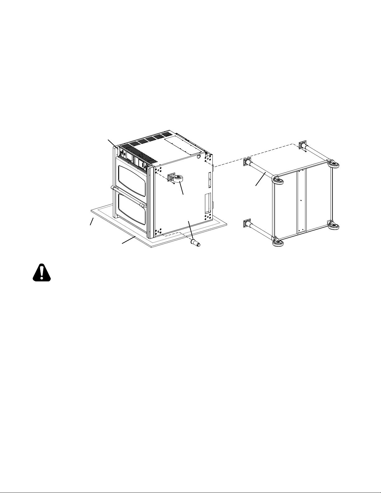
LEGS & CASTER INSTALLATION
Plywood
Control
The legs supplied with the unit must be installed, casters are an accessory and must be ordered
separately.
Legs are available for both the single and double deck installations.
SINGLE: require 27” legs or stands
DOUBLE: require 6” legs or casters.
To install the legs, place some cardboard on the oor and gently tip the oven onto its-back
or non-control side. Fasten all four legs to the oven’s corners using the sixteen 5/16” bolts
provided in the leg kit. Once legs securely in place, with assistance lift the unit upright, the
adjustable feet can adjusted to level the unit. A torpedo level placed on the oven rack will
assist in leveling the unit.
Panel UP
27" Legs
Caster
or
Adj. Foot
CAUTION
IL1215
Cardboard
These units may be placed on a curbed base.
CAREFULLY TILT OVEN ONTO ITS LEFT SIDE (CONTROL SIDE UP) WHEN INSTALLING
LEGS, FEET OR CASTERS. TURNING OVEN ONTO ITS RIGHT SIDE (CONTROL SIDE
DOWN) WILL DAMAGE THE CONTROL PANEL.
PROPER LEVELING IS ESSENTIAL TO PROPER BAKING PERFORMANCE.
CONVECTION OVENS INSTALLED WIHT CASTERS MUST HAVE THE FOLLOWING: A
CONNECTOR THAT COMPLIES WITH THE STANDARD FOR CONNECTORS FOR MOVABLE
GAS APPLIANCES ANSI Z21.69 LATEST EDITION, A QUICK DISCONNECT THAT COMPLIES
WITH THE STANDARD FOR QUICK DISCONNECT DEVICES FOR USE WITH GAS FUEL,
ANSI Z21.141 LATEST EDITION, A TETHER OR OTHER MEANS TO LIMIT APPLIANCE
MOVEMENT WITH OUT RELIANCE ON THE GAS SUPPLY PIPING. SECURELY ATTACH
THE TETHER TO THE EYEBOLT PROVIDED AT THE REAR OF THE APPLIANCE.
BEFORE LIGHTING, USE A SOAP AND WATER SOLUTION TO TEST ALL JOINTS FOR
GAS LEAKS.
2M-W741 Gas Full Size Computerized Convection Oven GCSF
8
Page 9
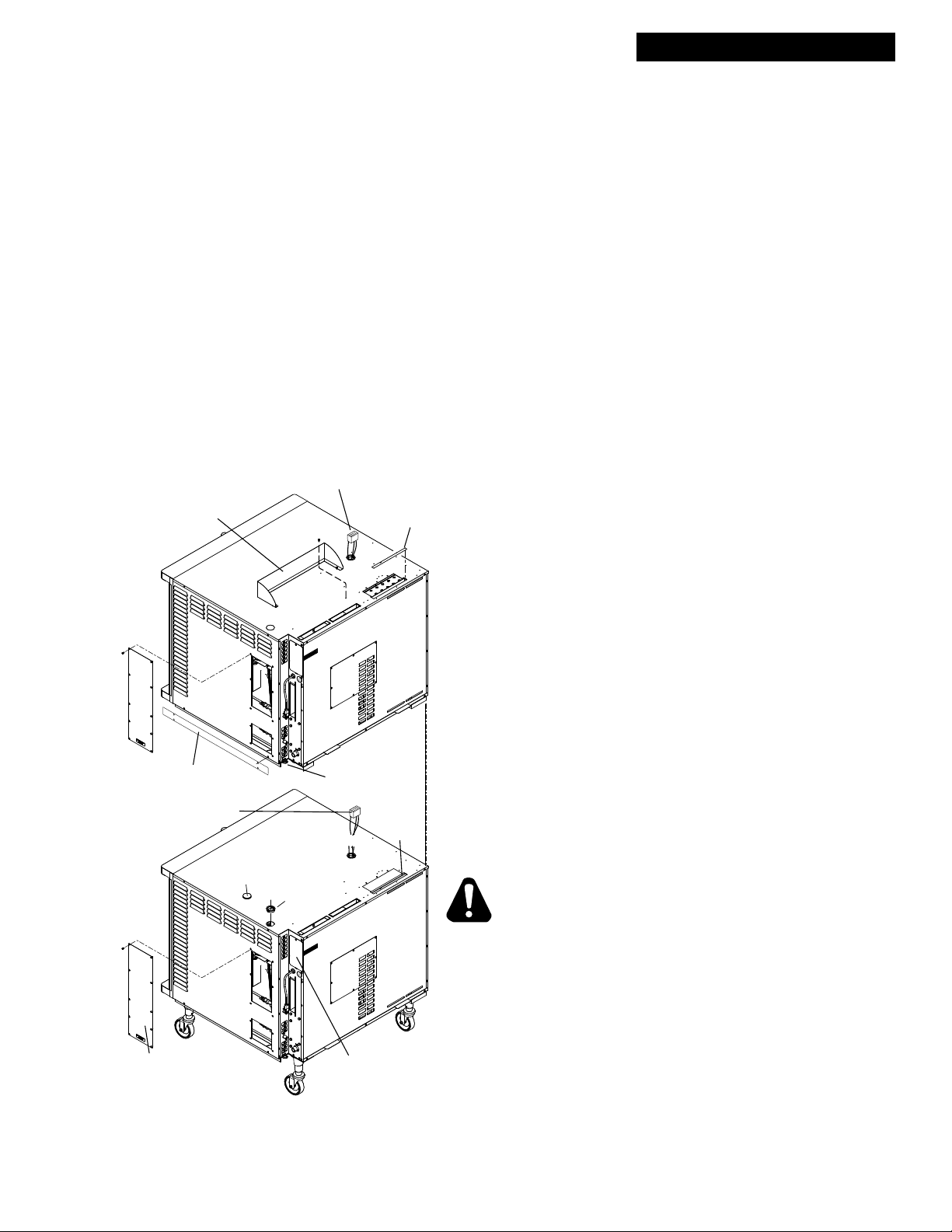
DOUBLE STACKED UNITS
STACKING INSTRUCTIONS, GCSF Oven
These stacking instructions apply when two units are being installed in a stacked arrangment only. When
an GCSF is in the top position, in a stacked assembly, the draft inducer wiring harness is needed to power
the inducer. The GCSF is the bottom position of a stacked assembly, must have the draft inducer wiring
harness removed.
When stacking an GCSF (gas) with a ECSF (electrical), put the GCSF on top to ensure proper venting of
combustion gasses.
1. Attach the feet or casters to the lower oven per the previous “Leg & Caster Installation” section.
2. Remove the Button Plug from the top right hand of the lower oven and replace it with the 1 3/4” plastic
electrical bushing provided in the stacking kit, see illustration.
3. Remove the LOWER OVEN, Draft Inducer Wiring Harness, this is not needed for the lower unit.
To accomplish this:
• Cut the 9 pin and the two single connectors coming through the top of the lower unit.
• Remove the Side Access Panel & the Terminal Block Access Panel on the lower oven.
• Disconnect the wires from the harness going to the terminal block.
• Locate the bundle of wires in the side access panel labeled “DRAFT INDUCER CONNECTION”,
disconnect the wires from the oven harness at the 6 pin connector.
• The draft inducer harness can now be removed from the unit by pulling the harness from the
control side through the rewall bushing
4. REMOVE THE INDUCER KNOCKOUT on the right rear
of the UPPER UNIT ONLY, prior to placing it into position.
DO NOT remove the knockout for the lower unit, doing so
will interupt proper gas venting from that unit.
5. Using the Strapping Plates (see stacking kit) secure the
two ovens together, by mounting them into the existing side
panel, using existing screws on both sides of the unit.
6. Install the vent shroud with 4 #10 sheet metal screws,
provided.
7. Remove the side access panel from the upper oven.
8. Locate the wire bundle labeled “Lower Oven Draft Inducer
Connection” in the upper oven. Pass this connection
through the plastic electrical bushing at the bottom of the
oven and into the lower oven.
EnviroZONE only: Install a 1 3/4” plastic electrical bushing,
replacing the knock-out directly behind the control cooling
fan of the lower oven.
9. In the lower oven, connect the 6 pin connector that was
passed through from the upper oven to the connection
marked “Draft Inducer Connection”
10. Replace the side access panels & attach the earthquake
strap (not included) to the eye bolt to the upper oven, see
illustration.
CAUTION
Vent Shroud
Upper
Oven
Strapping Plates
Lower Draft Inducer Harness
(9 pin connector)
Lower
Oven
2M-W741 Gas Full Size Computerized Convection Oven GCSF
Button Plug
Upper Draft Inducer Harness
(9 pin connector)
REMOVE
Inducer
Knockout
Eye Bolt
Do Not
Remove
Inducer
Knockout
Bushing
Side Access Panel
IL1270
Terminal Block
Access Panel
THE OVEN WEIGHS 520 LBS (238KG). FOR SAFE
HANDLING, INSTALLER SHOULD OBTAIN HELP AS
NEEDED, OR EMPLOY APPROPRIATE MATERIALS
HANDLING EQUIPMENT (SUCH AS A FORKLIFT, DOLLY,
OR PALLET JACK) TO REMOVE THE UNIT FROM THE
SKID AND MOVE IT TO THE PLACE OF INSTALLATION.
ANY STAND, COUNTER OR OTHER DEVICE ON WHICH
THE OVEN WILL BE LOCATED MUST BE DESIGNED TO
SUPPORT THE WEIGHT OF THE OVEN.
9
Page 10
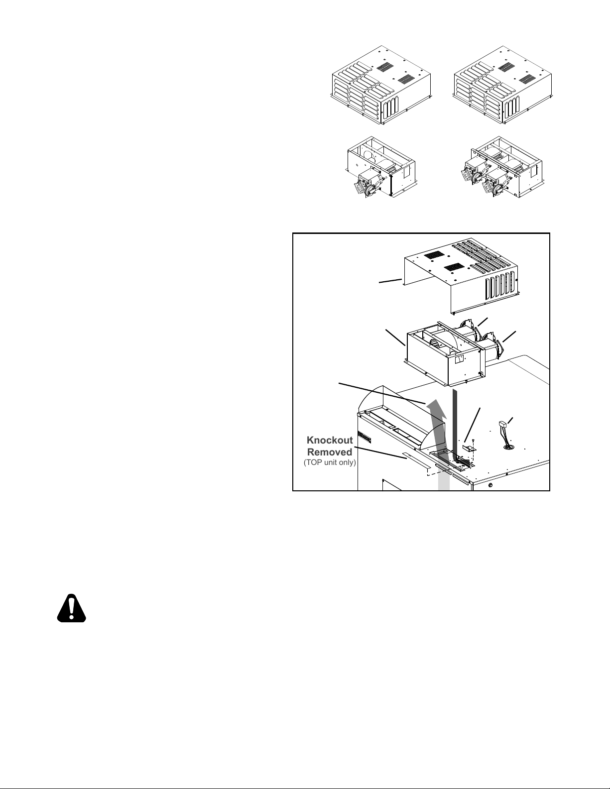
DRAFT INDUCER INSTALLATION
Knockout
Removed
(TOP unit only)
SINGLE UNIT
In single unit applications the oven must be
mounted to its cart before completing these
steps.
DOUBLE UNITS
When installing the draft inducer in a stacked
application, it must be completed only after
the previous “Stacking Instructions” have been
performed.
1. Install the bracket that came with the draft
inducer with three (3) of the #10 sheet metal
screws provided.
Single GCSF
One Motor
Double GCSF Stack
Two Motors
2. Make certain the knockout is
removed from the unit, top unit ONLY
in stacked situations. see illustration
shown here.
3. Place the draft inducer, without the
louvered cover, on top of the unit,
over the exhaust collector.
4. Slide the inducer forward until
secured under the attached bracket.
Using six (6) #10 sheet metal screws,
fasten this assembly onto the top of
Louvered
Cover
Draft Inducer
Lower Oven
Combustion
Exhaust Flow
Motor Top Unit
Motor Lower
the oven.
5. Connect the 9 pin and two single
electrical connections from the
Bracket
Inducer
Harness
draft inducer to the wiring harness
protuding from the top of the unit.
NOTE: There is no polarity
distinction between the single
connections.
6. Test the Inducer by plugging in the
120V connection to the oven (upper
Above: STACKED UNITS ONLY, Remove Knockout
before installing Draft Inducer.
oven on stacked assemblies) and
make sure the axial fan(s) on the draft inducer are turning. The fans will turn without the
controls being on.
IL1413
Unit
IL1272
7. Fasten the draft inducer cover to the top of the oven with the #10 sheet metal screws
provided.
IMPORTANT: IMPROPER DRAFT INDUCER INSTALLATION WILL ADVERSLY
AFFECT THE PERFORMANCE OF YOUR LANG EQUIPMENT.
EARTHQUAKE STRAPS
If the oven is to be installed with casters, it must be secured to the building structure. To do
this, attach an oven earthquake strap (not supplied) to the eye bolt (supplied) at the bottom
right corner of the oven. For stacked ovens, attach the strap to the eye bolt of the uppermost
oven. Connect the earthquake strap to the wall or other structure per instructions supplied
with the strap.
10
2M-W741 Gas Full Size Computerized Convection Oven GCSF
Page 11
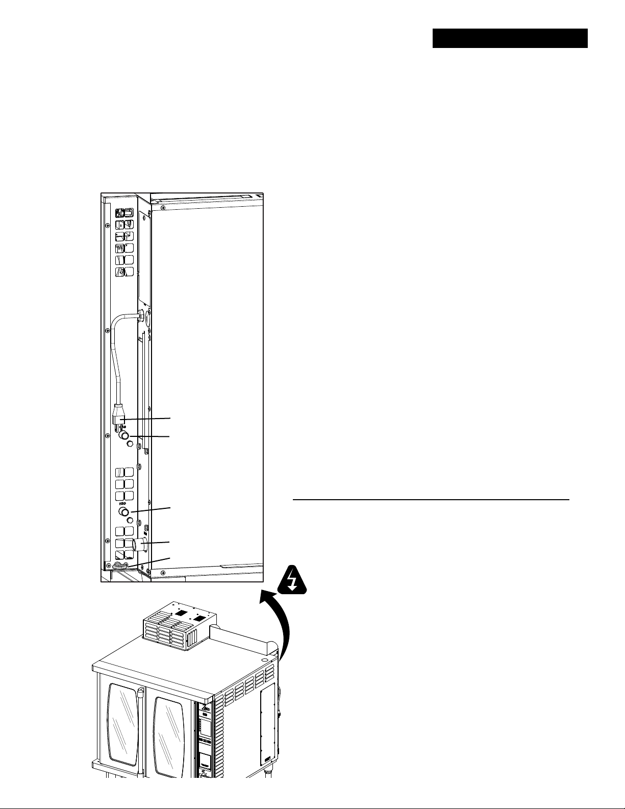
UTILITY INSTALLATION
WATER CONNECTION
It is vital that the water supply line be thoroughly ushed with clean water before being connected
to the oven’s water manifold.
After your water has been tested and meets the minimum requirements (see water requirements).
Connect water supply to 3/8” NPTM tting located at right rear corner of the oven. Once the
water manifold and water supply are connected to the oven turn the oven ON and press the
1-shot steam button for 1 minute to remove the air and any impurities from the system.
The water must continuously be within the specications (for this application) while this unit is
in service. Periodic testing may be needed to verify any changes in water conditions.
DRAIN CONNECTION
Attach drain plumbing to the ¾” NPTM oven drain tting located
at the lower rear right had corner of the oven.
Drains need to have a vent pipe attached. Typical venting is
accommodated by using a “T” off the drain pipe with an 8” to
10” open pipe in the top part of the “T”. for stacking, the drains
can be manifolded together with only the top drain vented.
ELECTRICAL CONNECTION
All electrical connections must be made in accordance with
local codes or in the absence of local codes with NFPA No.
70 latest edition (in Canada use: CSA STD. C22.1)
2M-W741 Gas Full Size Computerized Convection Oven GCSF
Plug
Gas Connection
Water Connection
Drain
Eye Bolt
IL1276
- IMPORTANT -
IF A SINGLE POWER SOURCE IS TO BE CONNECTED TO
BOTH OVENS, REMOVE THE CONTROL SIDE PANELS
AND RUN THE INTERCONNECTION WIRES THROUGH
THE 1” PLASTIC ELECTRICAL BUSHING RUNNING
BETWEEN THE TWO OVENS.
The electrical service entrance is provided by several
knockouts in the top right rear corner of each oven. Line
current information can be found on the unit’s data plate.
Voltage Phase Total kW Amps/Line
Single 120V 1 0.7 5.8
Double 120V 1 1.4 11.6
Supply wire size must be large enough to carry the amperage
load for the number of ovens being installed.
WARNING
THIS APPLIANCE IS EQUIPPED WITH A
3-PRONG (GROUNDING) PLUG FOR YOUR
PROTECTION AGAINST SHOCK HAZARD AND
MUST BE PLUGGED DIRECTLY INTO A PROPERLY
GROUNDED 3-PRONG RECEPTACLE. DO NOT CUT
OR REMOVE THIS GROUNDED PRONG FROM THE
PLUG.
11
Page 12
UTILITY INSTALLATION
GAS CONNECTION
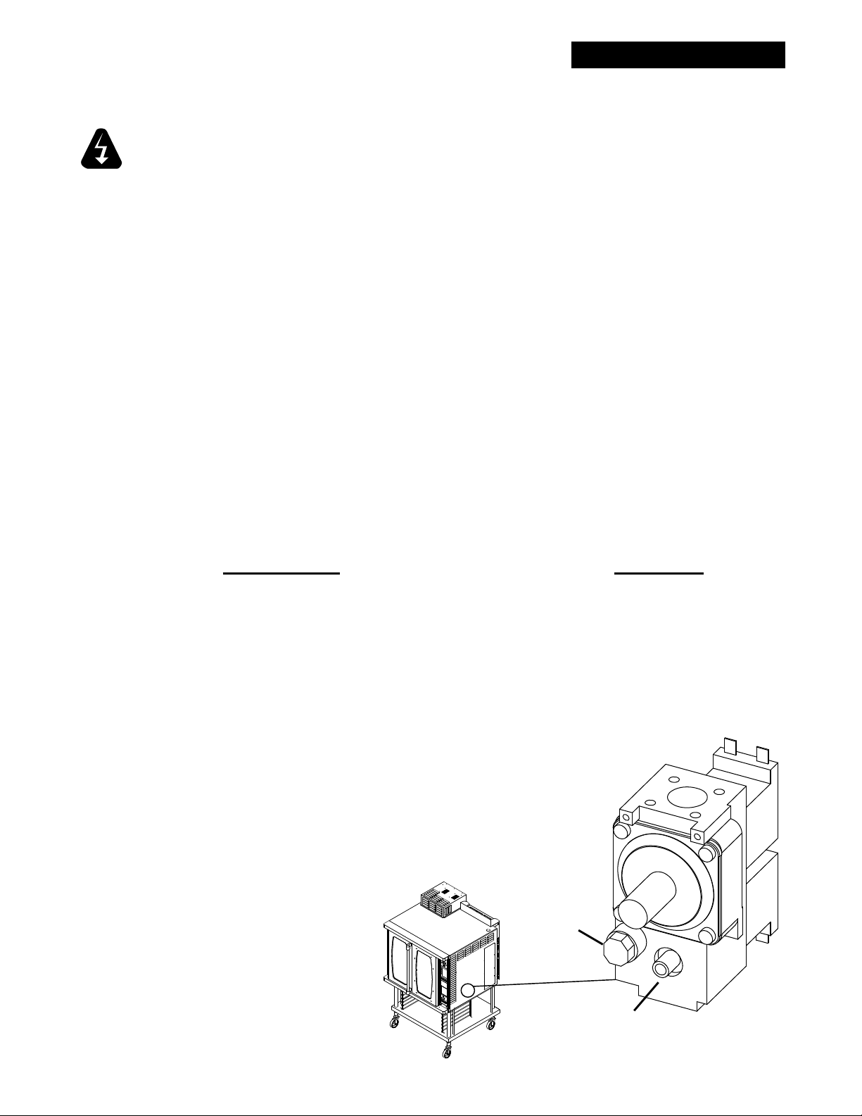
Attach gas plumbing to the 3/8” NPTM tting located on the right hand rear corner of the
oven.
WARNING
CONVECTION OVENS INSTALLED WITH CASTERS MUST HAVE THE FOLLOWING:
A CONNECTOR THAT COMPLIES WITH THE STANDARD FOR CONNECTORS FOR
MOVABLE GAS APPLIANCES ANSI Z21.69 LATEST EDITION, A QUICK DISCONNECT
THAT COMPLIES WITH THE STANDARD FOR QUICK DISCONNECT DEVICES FOR USE
WITH GAS FUEL, ANSI Z21.141 LATEST EDITION, A TETHER OR OTHER MEANS TO
LIMIT APPLIANCES MOVEMENT WITH OUT RELIANCE ON THE GAS SUPPLY PIPING.
SECURELY ATTACHED THE TETHER TO THE EYEBOLT PROVIDED AT THE REAR OF
THE APPLIANCE.
BEFORE LIGHTING, USE A SOAP AND WATER SOLUTION TO TEST ALL JOINTS FOR
GAS LEAKS.
PRESSURE TESTING THE GAS SUPPLY LINE
During pressure testing note the following:
1. The oven and its individual manual shut-off valve must be disconnected from the gas supply piping
system during any pressure testing of that system at test pressures in excess of 1/2 psig (3.45 kPa).
Turn OFF main gas shut-off valve or main gas supply line.
2. The oven must be isolated from the gas supply piping system by closing its individual manual shutoff valve during any pressure testing of the gas supply piping system at test pressures equal to or
less than 1/2 psig (3.45 kPa).
3. If incoming pressure is over 12" water column, a separate regulator for the oven must be installed
before the gas supply to the oven.
To prevent damage to the control valve regulator during the initial turn-on of
gas, it is very important to open the manual shut-off valve very slowly. After the
initial gas turn-on, the manual shut-off valve must remain open except during
pressure testing as outlined in the above steps or when necessary during service
maintenance.
NOTE: The supplied regulator is evaluated for a maximum gas supply pressure of
14" water column (34.5 mBar). The recommended maximum gas supply pressure
is 12" water column (29.9 mBar).
PRESSURE TESTING THE GAS CONTROL VALVE
Determine the outlet pressure is 4” W.C. by applying power to the valve
and energizing both valve solenoids. Use the outlet pressure tap connection on the underside of the valve body to monitor the outlet
pressure. The outlet pressure tap is a bleed hole with a cast
spigot, sealed with a threaded brass needle screw.
To monitor the outlet pressure, turn the screw in a
counterclockwise direction one or two turns
and t a 9 mm diameter exible tube
over the cast spigot. After making all valve adjustments and
obtaining the desired outlet
pressure, remove the exible
tube. Tighten the needle screw
by turning it clockwise with a
slotted screwdriver until hand
tight, sealing the bleed hole.
12
Pilot Tube
Connection
IL1407
Outlet Pressure
Tap Connection
2M-W741 Gas Full Size Computerized Convection Oven GCSF
Page 13
INITIAL START-UP
Pre-Power ON
After the oven is installed and connected to power, prior to turning on, verify the following:
• The doors open and close freely.
• All racks are in the oven correctly.
• All packing materials have been removed from the inside of the oven.
• Power is applied to the oven.
• Water is connected and turned on.
• Drains are connected.
NOTICE
During the rst few hours of operation you may notice a small amount of smoke
coming from the oven, and a faint odor. This is normal for a new oven and will
disappear within a few hours of operation.
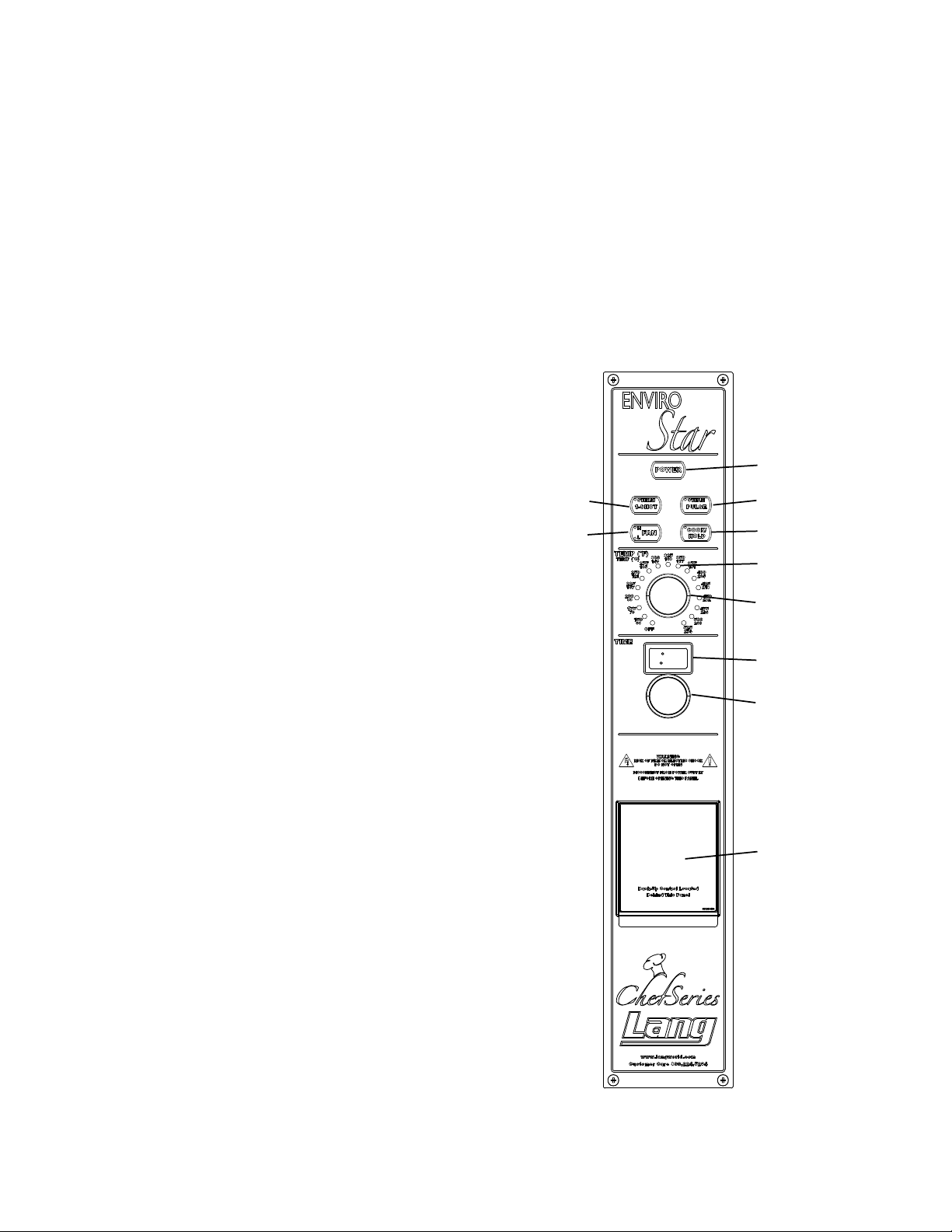
Enviro-STAR
Control Panel Denitions:
Power, - on/off button
Note: Fan remains on until oven cools down
to 250°F
1-Shot Steam - Provides single shot of steam
to the cooking chamber between 1 to 20 seconds. To adjust hold down button and turn
knob until desired time displays on LED.
Pulse Steam - Sends Steam Shots in
non-adjustable 1 second duration, to the
cooking chamber. Adjust the Pulse Steam
time between 1 to 120 minutes by holding
down the button and turning knob until the
desired time is displayed on the LED.
1-SHOT
STEAM
FAN
HI/LOW
POWER
PULSE STEAM
COOK-N-HOLD
LED TEMP
INDICATOR
TEMP KNOB
LED TIMER
SCREEN
TIMER KNOB
2M-W741 Gas Full Size Computerized Convection Oven GCSF
FAN - Fan has two speeds (L=LOW,
H=HIGH) Note: the fan will reverse directions
periodically during operations, this provides
for a more consistent bake.
COOK-N-HOLD - Once the cooking has
completed the unit will beep 5 times
(1-Shot Steam or Pulse Steam) this feature will
reduce the oven temperature to 150°F and
the cook-n-hold light will turn off. The oven
will remain at 150°F until the user begins
another cooking cycle or the unit is turned
off.
Note it may take as long as 1-hour for it to reach
150°F depending on the set cooking temperature.
This time must be taken into account when using
the Cook-N-Hold feature.
13
BACKUP CONTROL
ACCESS DOOR
Page 14

Enviro-STAR
Control Panel Denitions (Continued)
LED Temperature Indicator – Indicates the current temperature.
• V1.12 blinks with a call for heat,
• Solid means oven on set point.
Temperature Knob – Use to set oven temperature.
LED Timer Screen – Multifunctional digital readout.
• Reads out the time remain in the current cooking cycle.
• Reads out time when setting “Pulse Steam” interval time.
• Reads out time when setting “1 Shot Steam” duration.
Timer Knob – Sets cook time, Pulse Steam interval time and 1 Shot Steam duration.
Back UP Controls – Allows oven operation utilizing a completely separate set of manual
controls. Operation in Back-Up Mode is described in the “Operation with Back Up Controls”
section.
Initial Power On Test:
1. Follow these steps to verify the basic operation and temperature control capability of oven.
a) Turn Power On. Verify interior light and display comes on.
b) Set temperature to 300°F. Verify Temperature Indicator light is blinking.
c) Verify oven reaches set point & signals ‘Ready’ with an audible tone with in
12 Minutes. (starting with a cold oven)
d) Set timer to 10 Minutes and verify fan stops and reverses direction after
approximately 108 seconds. (complete reversing cycle takes 2 minutes.)
e) Open door and verify the Fan and Time Display stops then restarts when door is
closed.
f) Turn timer to zero, temp to zero.
g) Conrm fan stays on until temp cools to below approximately 250°F.
For units with water hookup for Steam.
2. Identify water purication system used: ________________________________________
(write “none” if no water treatment system is in use.)
3. Flush water system to clear tainted water from the install process. _____.
a) Put oven into Back-Up Mode and set temperature to approx. 400°F.
(Listen for contactor changing states)
b) Once up to temp, Use the steam bypass switch (spring loaded toggle switch in the
Back Up Access area) to ush the water through the oven for 1 minute.
c) Check water drain for proper operation.
2M-W741 Gas Full Size Computerized Convection Oven GCSF
14
Page 15
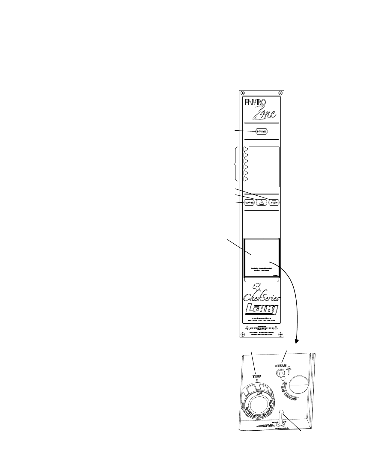
Enviro-ZONE
Steam Toggle Switch
POWER
PULSE STEAM
COOK-N-HOLD
1-SHOT
STEAM
FAN
HI/LOW
LED TEMP
INDICATOR
TEMP KNOB
LED TIMER
SCREEN
TIMER KNOB
BACKUP CONTROL
ACCESS DOOR
Control Panel Denitions:
Power – On/Off button. When switched on, the control will turn on the interior light and the
display. The fan is left off until there is a call for heat or a timer is started.
When the “Power” button is pushed to turn the oven off, the interior lights turn off, the front
display turn off.
Up – Allows you to scroll up.
Down – Allows you to scroll down.
Cancel – When scrolling through
menus this will allow you to back
up to the previous menu. In
program mode this will allow you
to back up to the previous step.
Function Keys – Keys are
active when a program option is
displayed on the display adjacent
to that key.
Back UP Controls – Allows oven
operation utilizing a completely
separate set of manual controls.
Operation in Back - Up Mode is
described in the “Operation with
Back Up Controls” section of this
manual.
BACKUP CONTROL
ACCESS DOOR
POWER
FUNCTION
KEYS
DOWN
UP
CANCEL
2M-W741 Gas Full Size Computerized Convection Oven GCSF
OPERATION WITH BACK UP CONTROLS
During Back-Up operation, the main control
panel is disabled by removing it’s power allowing
operator to utilize a completely separate set of
controls.
On both the Enviro-Zone & Enviro-Star models, the
back-up controls are located behind the Access
Door located just below the Control Panel. Inside
you will nd a Temperature Control Knob, a BackUp Control toggle switch and a spring loaded BackUp Steam toggle switch.
To enable Back-Up operation, throw the BackUp Control toggle switch to the ON position.
The oven’s convection fan will come on at High
speed / CCW and the heat can be controlled using the Temperature Knob. Steam may be applied
manually using the Back-Up Steam toggle switch.
Unlike normal operation, the Back-Up mode does
not employ energy saving processes or allow the
fan to reverse direction or change speeds.
Temperature Knob
IL1218
15
Control Toggle Switch
OCE/OCG BACK-UP CONTROLS
Page 16

Enviro-ZONE
Initial Power On Test:
1) Energize Oven and verify the basic operation and temperature control capability of oven.
a. Turn Power On. Verify interior lights and the display comes on. _____
b. Install a Temperature Meter thermocouple in center of oven cavity.
c. Using ‘Run Oven’ / ‘Manual Program’, set temperature to 300°F. _____
d. Verify oven reaches set point & signals ‘Ready’ with an audible tone with in
12 Minutes. (starting with a cold oven) _____
e. Press Manual Program again. Using the enter key and up button, enter time 00:10:00,
Press ‘Accept’ and then select shelf “C”. Verify the shelf timer starts count down;
Verify the fan stops and reverses direction after approximately 108 seconds.
(complete reversing cycle takes 2 minutes.) _____
f. Verify the measured temperature at the transition point (when heat contactor changes
states.) matches the temperature on the display panel. _____
g. Open door and verify the Fan stops then restarts when door is closed. _____
h. Press Cancel several times to return to “Run Oven” menu.
i. Conrm fan stays on until temp cools to below approximately 250°F. _____
For units with water hookup for Steam.
2) Identify water purication system used: _________________________________________
(write “none” if no water treatment system is in use.)
3) Flush water system to clear tainted water from the install process. _____.
a. Put oven into Back-Up Mode and set temperature to approx. 400°F.
b. Once up to temp, Use the steam bypass switch (spring loaded toggle switch) to
ush the water through the oven for 1 minute.
c. Check water drain for proper operation.
16
2M-W741 Gas Full Size Computerized Convection Oven GCSF
Page 17

OPERATION
Enviro-STAR Typical Operation Sequence:
ACTION RESULT
Press the POWER button Front panel lights up.
Select Fan Speed HI or Fan Speed LO. Selected Fan Speed light will be lit.
Adjust to desired temperature between 125° F Fan and heat come on. Fan will reverse direction every 2
and 525°F. (Minimum suggested temperature minutes (approximately) through out cooking process.
for operation with Steam is 250°F.).
Set Pulse Steam by pressing and holding Pulse Pulse Steam light will stay on. Digital display will momentarily
Steam button and selecting between 1 and show selected interval between steam pulses.
120 minutes interval between pulses
Temperature reaches Set Point. Set point reached within 12 minutes and audible tone signals.
Load Product into Oven. See Hints & Suggestions – “Loading the Oven.”
Set Timer Knob to desired cook time. Time starts timing down on digital display. If Pulse
Steam has been enabled, a 1 second shot of steam will be
applied at the selected interval.
Set Cook n Hold (Optional) Cook n Hold light comes on to indicate feature is enabled.
Cooking timer times out. Audible tone signals cook time complete.
If Cook n Hold feature is enabled, the oven temperature will
drop no lower than 150°F with the 150° time light on solid until
the timer is reset. The Cook n Hold light will go out at end of
timer.
Unload Oven See Hints & Suggestions – “Unloading the Oven”
Enviro-ZONE Typical Operation Sequence:
ACTION RESULT
Press the “POWER” button Control Panel comes on, display says “LANG, Run Oven,
Time/Date/Program.
Select “RUN OVEN”. Display will show a list of product to choose.
Select Product button next to Icon desired. Display says “Preheating to xxx°F”.
Beeper sounds briey. Display says “Ready”.
Select Function to start. Display shows possible product selection for that temperature.
Select Function to start. Display says “Select Shelf”, Place Product in oven
on selected shelf.
Press Function Button next to desired shelf Display will show icon chosen and begin to count down.
2M-W741 Gas Full Size Computerized Convection Oven GCSF
Beeper sounds continuously. Display shows “DONE” press button and remove product
from that shelf.
Oven is ready for another program.
17
Page 18
MAINTENANCE
• Water lters and conditioners should be inspected and replaced per their manufacturers
recommendations.
• Oven interiors should be wiped down daily and thoroughly cleaned weekly using warm water
and mild detergent. DO NOT use caustic cleaners.
• The appliance should be thoroughly checked at six-monthly intervals by a qualied
technician (heating unit, mechanical stability, corrosion...) with particular emphasis on all
control and safety devices.
CLEANING
• Always start with a cold oven.
• The stainless exterior can easily be cleaned using stainless steel cleaner.
• Always follow the cleaner manufacturer’s instructions when using any cleaner.
• Care should be taken to prevent caustic cleaning compounds from coming in contact with
the fan wheel.
• The oven racks, rack slides, may be cleaned outside the oven cavity using oven cleaner.
• Using any harsh chemicals will result in the removal of the ETC coating and etching of the
porcelain below it. The oven interior should only be cleaned using a mild soap and a non
metal scouring pad. DO NOT use caustic cleaners.
• Always apply stainless steel cleaners when the oven is cold and rub in the direction of the
metal’s grain.
WARNING
CAUTION
KEEP WATER AND SOLUTIONS OUT OF CONTROLS. NEVER SPRAY OR
HOSE CONTROL CONSOLE.
MOST CLEANERS ARE HARMFUL TO THE SKIN, EYES, MUCOUS
MEMBRANES AND CLOTHING. PRECAUTIONS SHOULD BE TAKEN TO WEAR
RUBBER GLOVES, GOGGLES OR FACE SHIELD AND PROTECTIVE
CLOTHING.
CAREFULLY READ THE WARNING AND FOLLOW THE DIRECTIONS ON THE
LABEL OF THE CLEANER TO BE USED.
NEVER LEAVE A CHLORINE SANITIZER IN CONTACT WITH STAINLESS STEEL
SURFACES LONGER THAN 10 MINUTES. LONGER CONTACT CAN CAUSE
CORROSION.
2M-W741 Gas Full Size Computerized Convection Oven GCSF
18
Page 19
CONVECTION OVEN BAKING GUIDE
CONVECTION OVENS IN GENERAL
• Convection ovens constantly circulate air over the product. This strips away the thin layer of moisture laden air from
the top of the product allowing heat to penetrate more quickly. This allows cooking times to be shortened and cooking temperatures reduced in convection ovens. Introducing Steam into the cooking process prevents the bake from
loosing moisture and allows for a better product.
• Applying steam to dough during rst 5 minutes, allows the yeast to work a little longer, allowing for better oven spring
and loaf volume keeping the outer layer exible and moist. Once the outside layer of the dough sets, gases in the loaf
can no longer expand to increase the loaf size.
• Steaming the dough as it bakes also gelatinizes starch on the outside layer, producing a bread with a crisp crust
and a brown crust color in varying degrees; too much steam results in an undesirable crust. Steam also helps
to prevent wild breaks in the loaves because it delays the setting of the bread’s crust, allowing it more time to
bake and brown. However, in contrast, during the last stages of baking, a dry oven is required when the crust is
browning; after the steam is removed, the gelatinized layer dries out forming a thick crunchy crust.
• The convection oven is an electro-mechanical piece of equipment and is designed to produce a consistent result.
Variations in results are therefore more likely due to differences in the preparation process.
DEFINITIONS
EnviroZone & EnviroStar
Cooking Time & Temperature: To convert standard deck oven recipes to convection oven recipes, start by
reducing the cooking temperature by 50 °F and the time by 25%.
Fan Speed Functions: The convection fan is programmable as either HI or LO speed. Most baking is done
with the fan speed set to high. Delicate products (i.e. Meringue pie) may require use of the low fan speed
setting.
EnviroZone
Cooking Curve: Cooking curve is a programmable function that adjusts the cooking time to
compensate for planned times when the oven temperature would be lower than the programmed temperature.
(i.e. temperature loses during loading and unloading). Cooking Curve 40%, is the most commonly used. Cooking
Curve settings from 0% (no time adjustment) to 100% (max time adjustment) are available. As a general rule the
longer the cooking time the lower the cooking curve, the shorter the cooking time the higher the cooking curve.
Pulse Fan Function: A Fan Pulse Rate setting allows the fan to be programmed to cycle on and off at regular inter-
vals during the period in the cooking cycle when there is no heat applied. (The computer will not allow the fan to
be OFF whenever the heat is ON).
Steam Programming: (Optional) One Second shots of steam can be introduced at programmable intervals. Steam
is typically only used when wanting to maintain moisture or achieve a specic result.
Tier Cooking: “Tiered” programming is the ability to change the cooking temperature or fan
function while cooking. (i.e. some products may require high heat and the fan to be LO for the rst
half of the cooking cycle. Tier 1 would be programmed with the Heat up and the fan LO and Tier
2 would then be programmed with the heat lowered and the fan HI for the remainder of the cycle.)
Multiple shelf baking function is disabled when using Tier Baking programs.
Vent Programming: The vent can be programmed to be either open or closed. Most baking should be done
with the vent closed. Open the vent only with high moisture products to avoid seepage of condensed
moisture around the front of the door.
2M-W741 Gas Full Size Computerized Convection Oven GCSF
BAKING HINTS
• Always maintain a consistent cooking process. Establish a process that works for you, write it down and stick to it.
Consistency in your cooking processes is very important to the quality of your bake.
• Always weigh your product. This will give you a more consistent size, color and quality.
• Do not overload pans or space product unevenly in the pan as this will create a uneven bake.
• Bent or warped pans can greatly affect the evenness of the bake.
• Always use the oven lights to view the product through the oven door windows. Do not open the oven doors during
baking as this will change the baking characteristics and produce erratic results.
• If using baker’s parchment, be sure the parchment does not blow over the product or obstruct air ow in any way. This
will create a uneven bake. Never use aluminum foil in your convection oven.
• Use proper sheet pans for baking. i.e. Aluminum pans have better heat transference than steel pans and
therefore yield much better bake results.
19
Page 20

LOADING THE OVEN
• When loading the oven, stage products and racks so the oven doors are opened for the least amount
of time during the loading process to minimize the loss of heat inside the oven.
• Center each pan on the oven shelves. Spaces should be maintained equally between the pan edges
and the oven walls, front and back. This will allow for an even distribution of airow. The better the
air ow around the product, the better and more consistent the bake.
• Load the pans on the shelves as close to equal distant apart as possible. Even vertical spacing of the
pans on shelves 1 thru 6 inside the oven is important to the proper circulation of air and therefore will
have an effect on the quality of your bake.
• When loading the oven randomly, (Different times for different shelves) load the oven from the
center shelf out with even vertical spacing.
• When loading multiple pans at the same time, load the shelves spaced as equal distant as possible with even vertical spacing.
UNLOADING THE OVEN
• Unload the top shelf before the bottom shelves. This is necessary because it is a characteristic of
all ovens that, after the fan shuts down, rising heat and the hot oven ceiling causes the top shelf to
bake quicker. This characteristic is more pronounced when baking at higher temperatures and/or for
prolonged periods of time.
• Always stage your product racks so that you can unload quickly with the door open for a minimal
amount of time. This is to preserve the temperature inside the oven cavity for your next round of
baking.
ALWAYS KEEP THE AREA NEAR THE UNIT FREE FROM COMBUSTIBLE MATERIALS.
CAUTION
KEEP FLOOR IN FRONT OF EQUIPMENT CLEAN AND DRY. IF SPILLS OCCUR,
CLEAN IMMEDIATELY TO AVOID THE DANGER OF SLIPS OF FALLS.
2M-W741 Gas Full Size Computerized Convection Oven GCSF
20
Page 21
EnviroZONE PROGRAMING
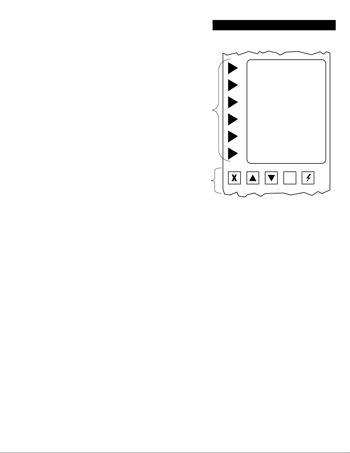
When using the EnviroZone Control Panel follow
these simple steps.
Function Keys: Are active when selecting an option
that is displayed on the LCD Screen.
Function Buttons:
Cancel: During Program Mode it will take you to
the next step, otherwise it will take you back to the
previous menu.
Up & Down: Will move you through the selections/
settings displayed on the LCD Screen which will be
used when programming your specic
requirements. (Example: access codes,
temperature settings, cooking time, curve , fan
speed etc.)
On/Off: Main Power Switch
Function
Keys
Function
Buttons
EnviroZONE PROGRAMING
LCD Screen
Cancel Up Down Light On/Off
IL1221
Programming Step Contents:
Step 7 Select Product Icon,
Step 8 Select Product Name,
Step 9 Select Product Temperature,
Step 10 Select Tier Cook Time,
Step 11 Select Cooking Curve,
Step 12 Select Fan Speed,
Step 13 Select Steam One Shot Seconds,
Step 14 Select Pulse Rate,
Step 15 Select Vent Start Minutes,
2M-W741 Gas Full Size Computerized Convection Oven GCSF
Step 16 Select Vent Open Minutes,
Step 18 Continue To Next Tier
Cooking Curve: Cooking curve is a programmable function that adjusts
the cooking time to compensate for planned times when the oven temperature would be lower than the programmed temperature.
(i.e. temperature loses during loading and unloading). Cooking Curve
40%, is the most commonly used. Cooking Curve settings from 0%
(no time adjustment) to 100% (max time adjustment) are available. As
a general rule the longer the cooking time the lower the cooking curve,
the shorter the cooking time the higher the cooking curve.
Pulse Fan Function: A Fan Pulse Rate setting allows the fan to be pro-
grammed to cycle on and off at regular intervals during the period in
the cooking cycle when there is no heat applied. (The computer will
not allow the fan to be OFF whenever the heat is ON).
Steam Programming: (Optional) One Second shots of steam can be in-
troduced at programmable intervals. Steam is typically only used when
wanting to maintain moisture or achieve a specic result.
Tier Cooking: “Tiered” programming is the ability to change the cooking
temperature or fan function while cooking. (i.e. some products may
require high heat and the fan to be LO for the rst half of the cooking
cycle. Tier 1 would be programmed with the Heat up and the fan LO
and Tier 2 would then be programmed with the heat lowered and the
fan HI for the remainder of the cycle.)
Multiple shelf baking function is disabled when using Tier Baking
programs.
Vent Programming: The vent can be programmed to be either open or
closed. Most baking should be done with the vent closed. Open the
vent only with high moisture products to avoid seepage of condensed
moisture around the front of the door.
21
Page 22
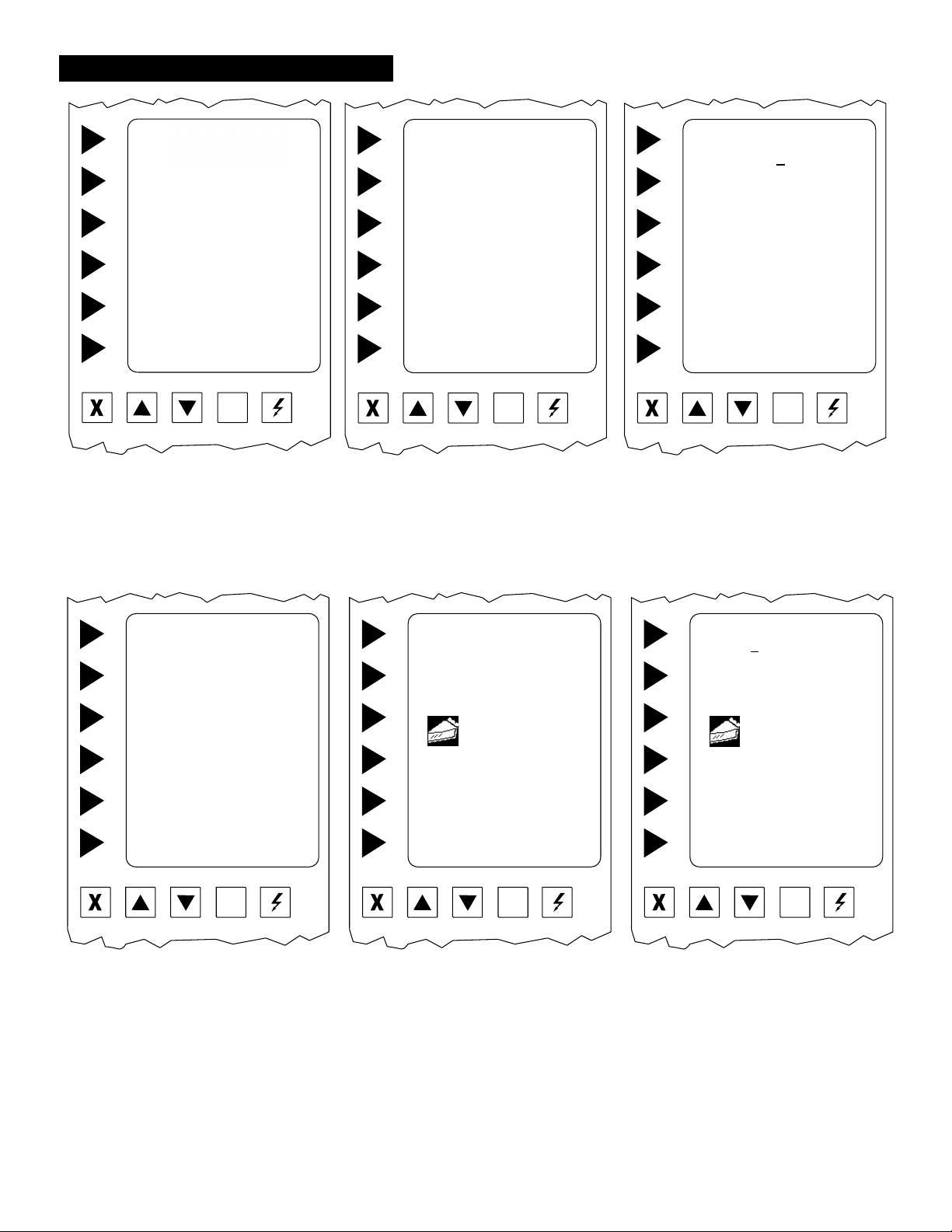
EnviroZONE PROGRAMING
◄ RUN OVEN
◄ TIME / DATE / PROGRAM
TIME DATE TEMP STATUS
12:00 01/01/01 325 STANDBY
Cancel Up Down Light On/Of f
Step 1. Turn power switch on. If the oven
is on, press cancel until the above
screen is displayed.
Step 2. Select TIME/DATE/PROGRAM
◄ DISPLAY PRODUCT
◄ TIMER ONLY
◄ SET TIME / DATE
◄ PROGRAM COMPUTER
TIME DATE TEMP STATUS
12:00 01/01/01 325 STANDBY
Cancel Up Down Light On/Of f
Step 3
Select PROGRAM COMPUTER
ENTER ACCESS CODE
A
USE ▲▼ KEYS TO SELECT
THEN PRESS ENTER
◄ ENTER
PRESS CANCEL TO QUIT
Cancel Up Down Light On/Of f
Step 4 Using the ▲▼ arrows, enter
access code “A B C D E F”
hitting ENTER after each letter.
◄ PROGRAM PRODUCT
◄ EDIT READY ZONE
◄ EDIT ACCESS CODE
◄ ENABLE MANUAL PRODUCT
◄ CONFIGURE TIME OF DAY
Cancel Up Down Light On/Of f
Step 5 Select PROGRAM PRODUCTS
then
Step 6 Select
CREATE NEW PRODUCTS
SELECT PRODUCT ICON
USE ▲▼ KEYS TO SELECT
THEN PRESS
ENTER TO ACCEPT
APPETIZER A
◄ ENTER
Cancel Up Down Light On/Of f
Step 7 Select Product Icon,
This is the rst screen in creating a
product program. Press ▲▼ until
you nd a icon which resembles
your product.
Select ENTER to accept the icon
and move to the next screen.
SELECT PRODUCT NAME
APPETIZER A
USE ▲▼ KEYS TO SELECT
APPETIZER A
◄ ACCEPT
◄ ENTER
Cancel Up Down Light On/Of f
Step 8 Select Product Name,
This is where you enter the name
of the product into the computer.
Using the ▲▼ keys type over the
default name, blank space is before
the A and after the 9.
Select ACCEPT to continue.
Note: Curser must be moved past the last
digit to save the entire entry.
22
Page 23
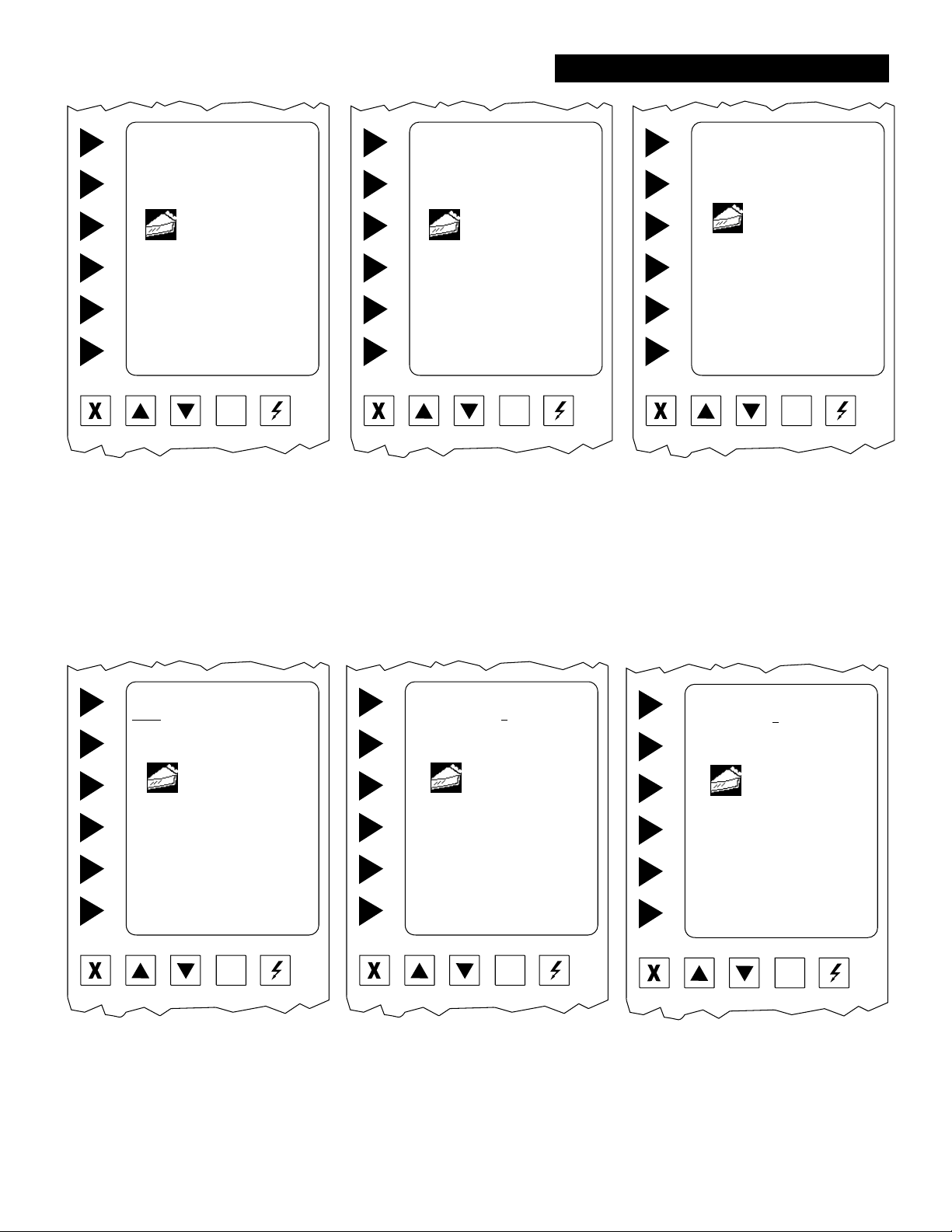
EnviroZONE PROGRAMING
SELECT PRODUCT TEMP
100
USE ▲▼ KEYS TO SELECT
APPLE
TIER 1
◄ ACCEPT
◄ ENTER
Cancel Up Down Light On/Of f
Step 9 Select Product Temperature,
Press the ▲▼ to select the rst
digit, then press ENTER to move
to the next digit. It will
automatically move to the next
screen after the third digit.
SELECT TIER COOK TIME
00:45:00
USE ▲▼ KEYS TO SELECT
APPLE
TIER 1
TEMP: 320°F
◄ ACCEPT
◄ ENTER
Cancel Up Down Light On/Of f
Step 10 Select Tier Cook Time,
Time is entered in
hours:minutes:seconds.
The maximum is 12:59:59.
Select ENTER to move the cursor
to the place you want to enter the
number.
Select ACCEPT to continue.
SELECT COOKING CURVE
000%
USE ▲▼ KEYS TO SELECT
APPLE
TIER 1
TEMP: 320°F TIME: 00:45:00
◄ ACCEPT
◄ ENTER
Cancel Up Down Light On/Of f
Step 11 Select Cooking Curve,
press ▲▼ to select the numbers,
press the ENTER to move the
cursor to the next space.
Cooking Curve may be any
number between 0% and 100%.
Select ACCEPT to continue.
SELECT FAN SPEED
HIGH LOW
USE ▲▼ KEYS TO SELECT
APPLE
TIER 1
TEMP: 320°F TIME: 00:45:00
COOKING CURVE: 80%
◄ ACCEPT
◄ ENTER
Cancel Up Down Light On/Of f
Step 12 Select Fan Speed,
Press the ▲▼ to move the curser
between the HIGH and LO
settings.
Press ENTER to make your
selection and move to the next
screen.
Steam One Shot Seconds
00
USE ▲▼ KEYS TO SELECT
APPLE
TIER 1
TEMP: 320°F TIME: 00:45:00
FAN: HI
CCURVE: 80%
◄ ACCEPT
◄ ENTER
Cancel Up Down Light On/Of f
Step 13 Select Steam One Shot Seconds,
Press the ▲▼ to select the rst
digit, then press ENTER to move
to the next digit.
Select ACCEPT to continue.
23
SELECT PULSE RATE
100%
USE ▲▼ KEYS TO SELECT
APPLE
TIER 1
TEMP: 320°F TIME: 00:45:00
FAN: HI
CCURVE: 80%
◄ ACCEPT
◄ ENTER
Cancel Up Down Light On/Of f
Step 14 Select Pulse Rate,
Press the ▲▼ to select the rst
digit, then press ENTER to move
to the next digit. It will automatically move to the next screen after
the third digit.
Page 24
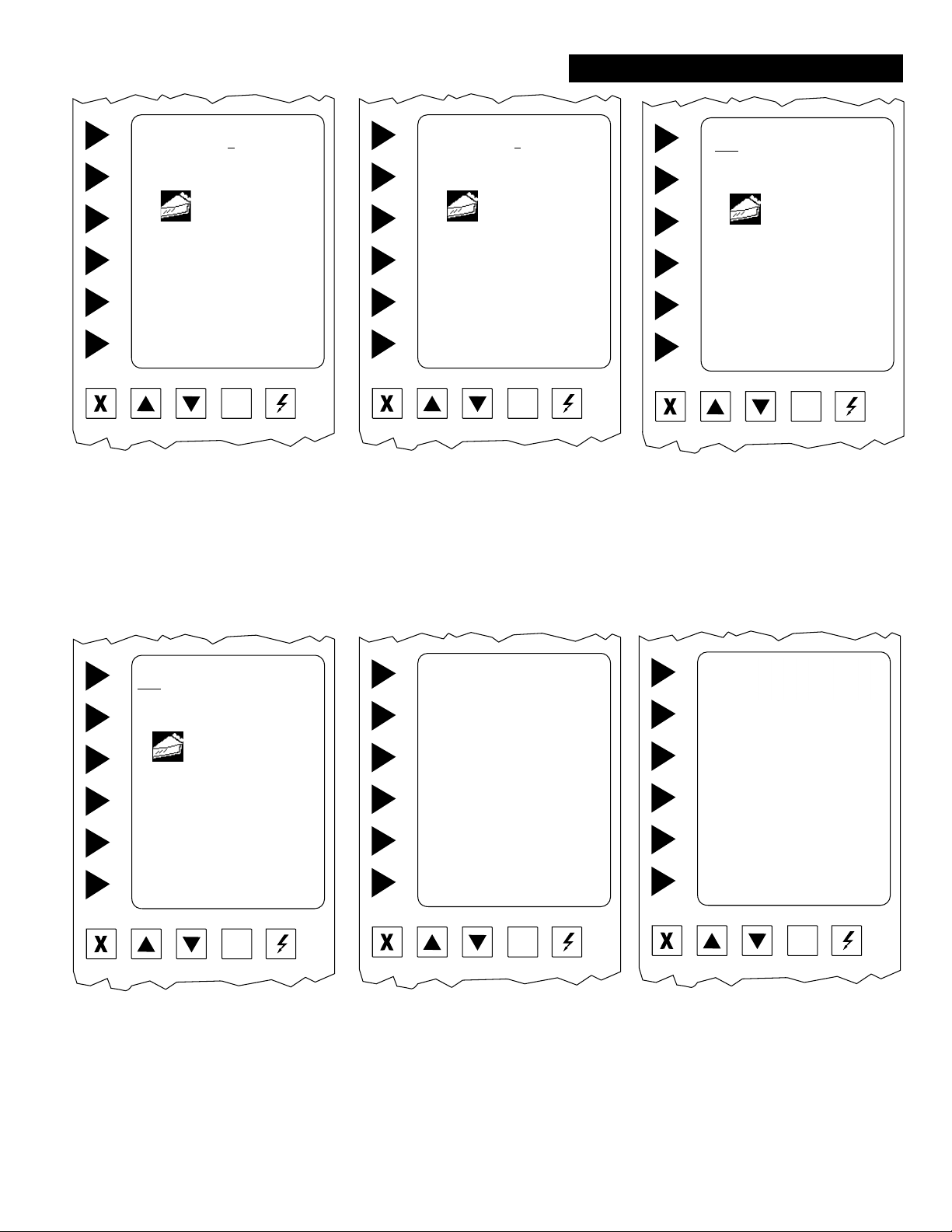
EnviroZONE PROGRAMING
Select Vent Start Minutes
000
USE ▲▼ KEYS TO SELECT
APPLE
TIER 1
TEMP: 320°F TIME: 00:45:00
FAN: HI RATE: 100%
CCURVE: 80%
BOTH STEAM: 03, 050
◄ ACCEPT
◄ ENTER
Cancel Up Down Light On/Of f
Step 15 Select Vent Start Minutes,
Press the ▲▼ to select the rst
digit, then press ENTER to move
to the next digit. It will automatically move to the next screen after
the third digit.
Select ACCEPT to continue.
Select Vent Open Minutes
000
USE ▲▼ KEYS TO SELECT
APPLE
TIER 1
TEMP: 320°F TIME: 00:45:00
FAN: HI RATE: 100%
CCURVE: 80% Vent: 4, 1,
BOTH STEAM: 03, 050
◄ ACCEPT
◄ ENTER
Cancel Up Down Light On/Of f
Step 16 Select Vent Open Minutes,
Press the ▲▼ to select the rst
digit, then press ENTER to move
to the next digit. It will automatically move to the next screen after
the third digit.
Select ACCEPT to continue.
YES NO
CORRECT?
USE ▲▼ KEYS TO SELECT
APPLE
TIER 1
TEMP: 320°F TIME: 00:45:00
FAN: HI RATE: 100%
CCURVE: 80%
BOTH STEAM: 03, 050
◄ ACCEPT
◄ ENTER
Cancel Up Down Light On/Of f
Step 17 Correct
The computer is asking if the
display is correct. If any part of
the program is incorrect press ▲▼
NO, and you will be taken back to
Step 7.
Selecting YES will advance the
screen.
CONTINUE TO NEXT TIER
YES NO
USE ▲▼ KEYS TO SELECT
APPLE
TIER 1
TEMP: 320°F TIME: 00:45:00
FAN: HI RATE: 100%
CCURVE: 80%
BOTH STEAM: 03, 050
◄ ACCEPT
◄ ENTER
Cancel Up Down Light On/Of f
Step 18 Continue To Next Tier
The cursor automatically appears
on NO. Select ENTER or
ACCEPT to end programming
or
move the curser ▲▼ to YES.
This will allow your to enter another tier to this program, repeating steps 6 - 14 to program second
tier.
◄ CREATE NEW PROGRAM
◄ EDIT PRODUCT
◄ DELETE PROGRAM
◄ EDIT PROGRAM
Cancel Up Down Light On/Of f
Step 19 After programing the last tier, the
computer will automatically advance the screen to program more
products. If no other products
need to be programmed, select
CANCEL three times to advance
screen to the boot up screen.
24
◄ RUN OVEN
◄ TIME / DATE / PROGRAM
TIME DATE TEMP STATUS
12:00 01/01/01 325 STANDBY
Cancel Up Down Light On/Of f
Step 20 Boot-up Screen
You may now preheat the oven
for any product you have programmed.
Step 21 Select RUN OVEN
Page 25
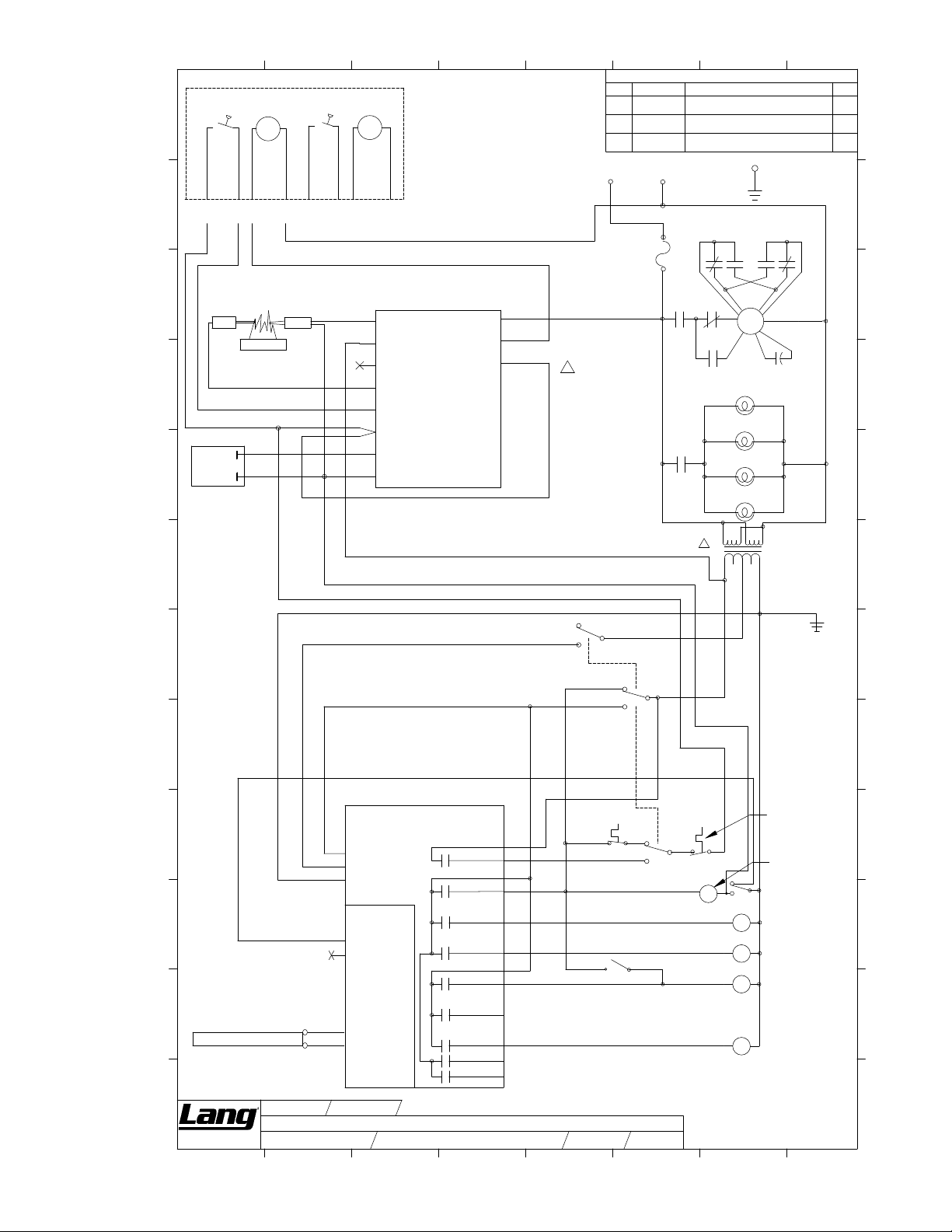
L
K
J
I
H
G
1
AIR PROVING
SWITCH 1
37
FLAME
SENSOR
GAS
VALV E
54
BURNER
37
55
DRAFT
INDUCER
MOTOR 1
51
34
DI2
37
AIR PROVING
SWITCH 2
37
N
TO OTHER OVEN
IGNITER
37
REVISIONS
DESCRIPTION OF CHANGEDATE/ECO
FOR CLARIFICATION
IGNITION CONTROL
20
PUR
11
Fan
Motor
RED
MR3
BLK
12
LAMP1
LAMP2
LAMP3
LAMP4
C
7
GND
MR1
21
YEL
N
WHT
CAPACITOR
(P/N 40704-14)
4
321
T1
24 VAC CT
YEL
N
8
DR
LRC
L
LRC
JRA
K
19
N
J
I
H
N
G
DRAFT
INDUCER
MOTOR 2
DI2
52
30
3
DRAFT
INDUCER
(MOUNTED ON
TOP OF OVEN)
NOTE: DRAFT INDUCER USED
FOR SINGLE AND DOUBLE OVENS.
THEREFORE, ON SINGLE OVEN
ONLY ONE DRAFT INDUCER AND AIR
PROVING SWITCH IS USED.
N
S1
L1
2
51
54
L2
S2
53
PS
54
W
37
MV1
55
GND
34
IGNITION
CONTROL
4
5
REV.
120 VAC 1 PHASE
10
F1
51
F2
37
R
E
C
D
E
A
6
12/5/2007
ECO# 6361
2/12/2008
ECO# 6582
10/28/2013
ECO 13306
ADDED NOTE AND UPDATED T1 WIRING
ADDED R TERMINAL AND JUMPER TO
CHANGED R TERMINAL CONNECTION
FROM L1 TERMINAL TO W TERMINAL
N
A
24
F7
15A
SC15
PUR
10
13
MR2
15
LR1
10
NOTE: ON TRANSFORMER T1,
CONNECT 1 (BLK) & 3 (BLK-RED)
TOGETHER TO WIRE 10. CONNECT
2 (BLK-YEL) & 4 (BLK-WHT)
30
TOGETHER TO WIRE N.
34
2M-W741 Gas Full Size Computerized Convection Oven GCSF
SW2
BACK-UP SWITCH
F
46
BACK-UP SWITCH
35
30
32
31
F
36
GND
E
NTROL CIRCUIT BOARDCO
D
46
32
C
B
RTD
38
15 PIN OUTPUT CONNECTOR
36
PIN 1
PIN 2
PIN 3
PCB
10 PIN INPUT
CONNECTOR
PIN 1
PIN 2
PIN 7
PIN 8
PIN 4
PIN 5
PIN 6
PIN 7
PIN 8
PIN 9
PIN 10
PIN 11
PIN 12
PIN 13
PIN 14
PIN 15
30
39
36
35
41
42
36
43
SPARE
48
SPARE
BACK-UP T-STAT
SW4
SW2
35
35
SW6
47
BACK-UP
SWITCH
SW3
37
45
MR2
BACK-UP STEAM
SWITCH
OVER TEMP
SWITCH
34
38
DOOR SWITCH
SW1
MOTOR RELAY -
MR1
FWD/REVERSE
LIGHT RELAY
LR1
SV1
WATER SOLENOID
32
MR3
HI/LOW SPEED
MOTOR RELAY
- RUN
E
D
C
B
A
Manufacturing
Company
DWN. BY :
DESCRIPTION:
CAD FILE :
1
DWN. DATE : 8/10/05
HJP
WD GCSF ENVIROSTAR 120V
146-799-11.DWG
2
DWG. NO:
3
2M-146-799-11
4
25
SHEET
5
OF
REV:
1
1
E
6
7
A
8
Page 26
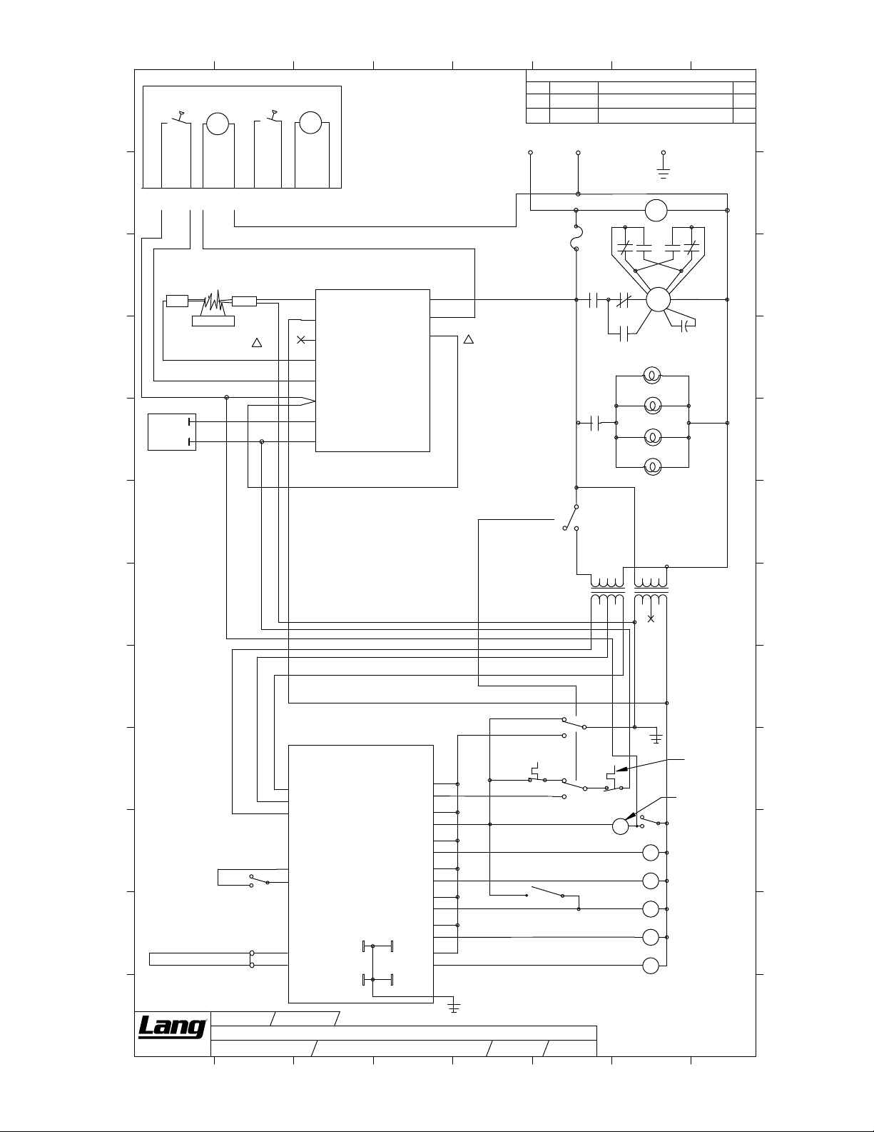
3
7
L
1
AIR PROVING
SWITCH 1
DRAFT
INDUCER
MOTOR 1
DI2
2
AIR PROVING
SWITCH 2
DRAFT
INDUCER
MOTOR 2
DI2
4
DRAFT
INDUCER
(MOUNTED ON
TOP OF OVEN)
NOTE: DRAFT INDUCER USED
FOR SINGLE AND DOUBLE OVENS.
THEREFORE, ON SINGLE OVEN
ONLY ONE DRAFT INDUCER AND AIR
PROVING SWITCH IS USED.
5
REV.
120 VAC 1 PHASE
E
F
A
6
6/28/2012
ECO 11914
10/30/2013
ECO 13311
N
REVISIONS
DESCRIPTION OF CHANGEDATE/ECO
ADDED XFMR NUMBERS TO T1 & T2
CHANGED R TERMINAL CONNECTION
FROM L1 TERMINAL TO W TERMINAL
GND
8
DR
JMM
L
JRA
K
37
J
FLAME
SENSOR
51
54
N
IGNITER
BURNER
I
37
GAS
VALV E
H
G
F
55
34
54
37
TO OTHER OVEN
30
E
37
51
N
A
24
F7
15A
SC15
PUR
10
64
(31400-27)
TI
10
12
LR1
SW2
13
0 VAC
4660
MR3MR2
15
62
10
IGNITION
CONTROL
F1
51
F2
37
R
E
BACK-UP SWITCH
24 VAC CT
S1
52
L1
32
L2
S2
53
PS
54
W
37
MV1
55
GND
34
20
11
RED
12
PUR
BLK
LAMP1
LAMP2
LAMP3
LAMP4
COOLING FAN
CF1
MR1
21
YEL
N
Fan
Motor
WHT
CAPACITOR
(P/N 40704-14)
12
0 VAC
T2
(31400-34)
24 VAC CT
19
YEL
N
K
N
J
I
H
N
G
F
E
D
C
B
A
Manufacturing
RTD
Company
1
60
46
62
46
60
SW7
DOOR SWITCH #2
DWN. BY :
HJP
DESCRIPTION:
CAD FILE :
WD OCG ENVIRO ZONE 120V
FROM SOLIDWORKS
2
CONTROL CIRCUIT BOARD
JP40
38
JP35
33
JP21
DWN. DATE : 8/10/05
DWG. NO:
3
GP3
GP3
146-799-13
GP4
GP4
JP2
JP13
JP11
JP15
JP14
JP1
JP12
4
26
36
39
36
35
36
36
42
36
43
36
36
48
41
44
GND
32
30
E
35
36
BACK-UP
35
SHEET
5
T-S TAT
SW4
35
1
SW2
BACK-UP SWITCH
SW2
SW6
OF
1
47
REV:
F
SW3
45
BACK-UP
SWITCH
BACK-UP STEAM
SWITCH
MR2
34
GND
37
SW1
MR1
LR1
SV1
VS1
MR3
76
OVER TEMP
SWITCH
MOTOR RELAY
- RUN
DOOR SWITCH #1
MOTOR RELAY FWD/REVERSE
LIGHT RELAY
WATER SOLENOID
VENT SOLENOID
32
HI/LOW SPEED
D
2M-W741 Gas Full Size Computerized Convection Oven GCSF
C
B
A
8
Page 27
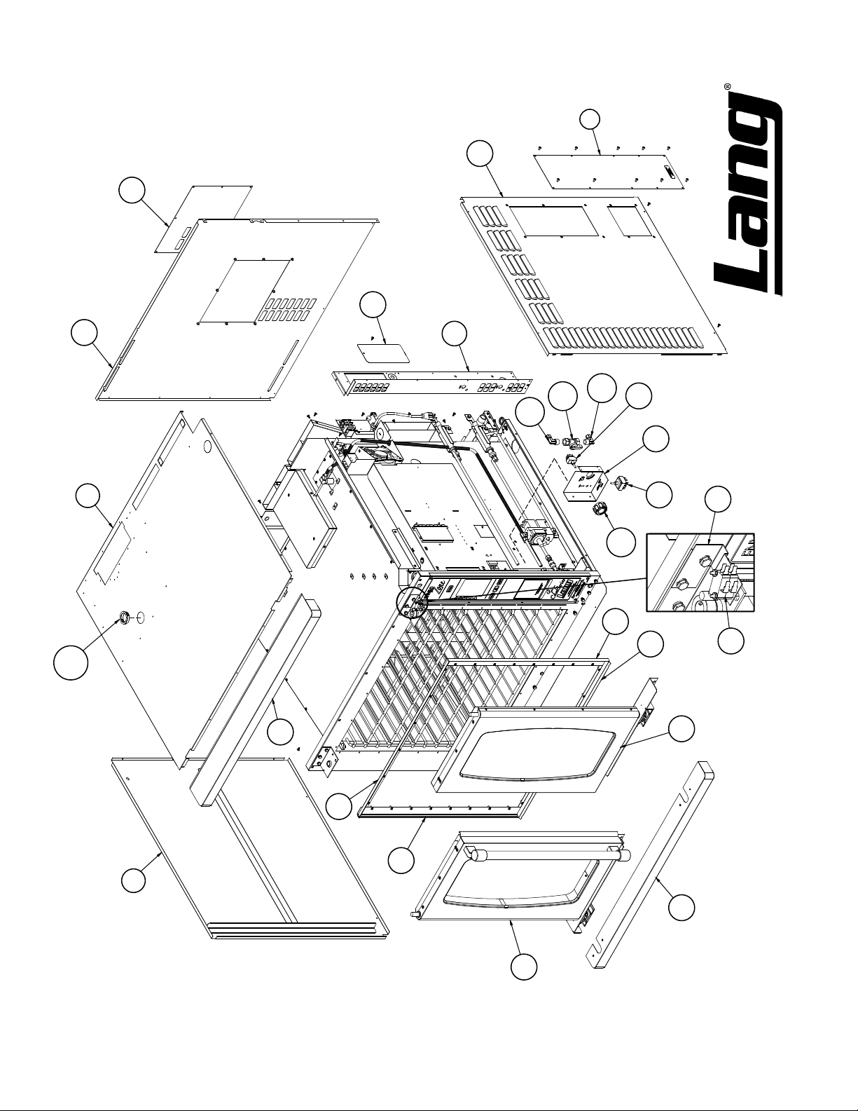
45
4
75
IL1313 Rev. - 3/28/07
14
76
2
131
22
1
119
125
119
86
9
87
128
21
18
20
85
70
19
18
3
23
GCSF Main Exterior Assy
69
NO REPRODUCTION OR DISCLOSURE OF ITS CONTENTS IS PERMITTED.
MODEL:
THIS DRAWING CONTAINS INFORMATION CONFIDENTIAL TO STAR MFG. INT'L. INC.
Page 28
101
110
73 74
100
90
89
42
99
Thermostat
Interior Lights
68
82
111
133
11
11
106
12
IL1312 Rev. A 6/10/08
65
132
Circulation Fan
109108
Temp Probe
60
16
107
62
61
138
15
144
77
143
63 64
Burner & Heat Exchanger
59
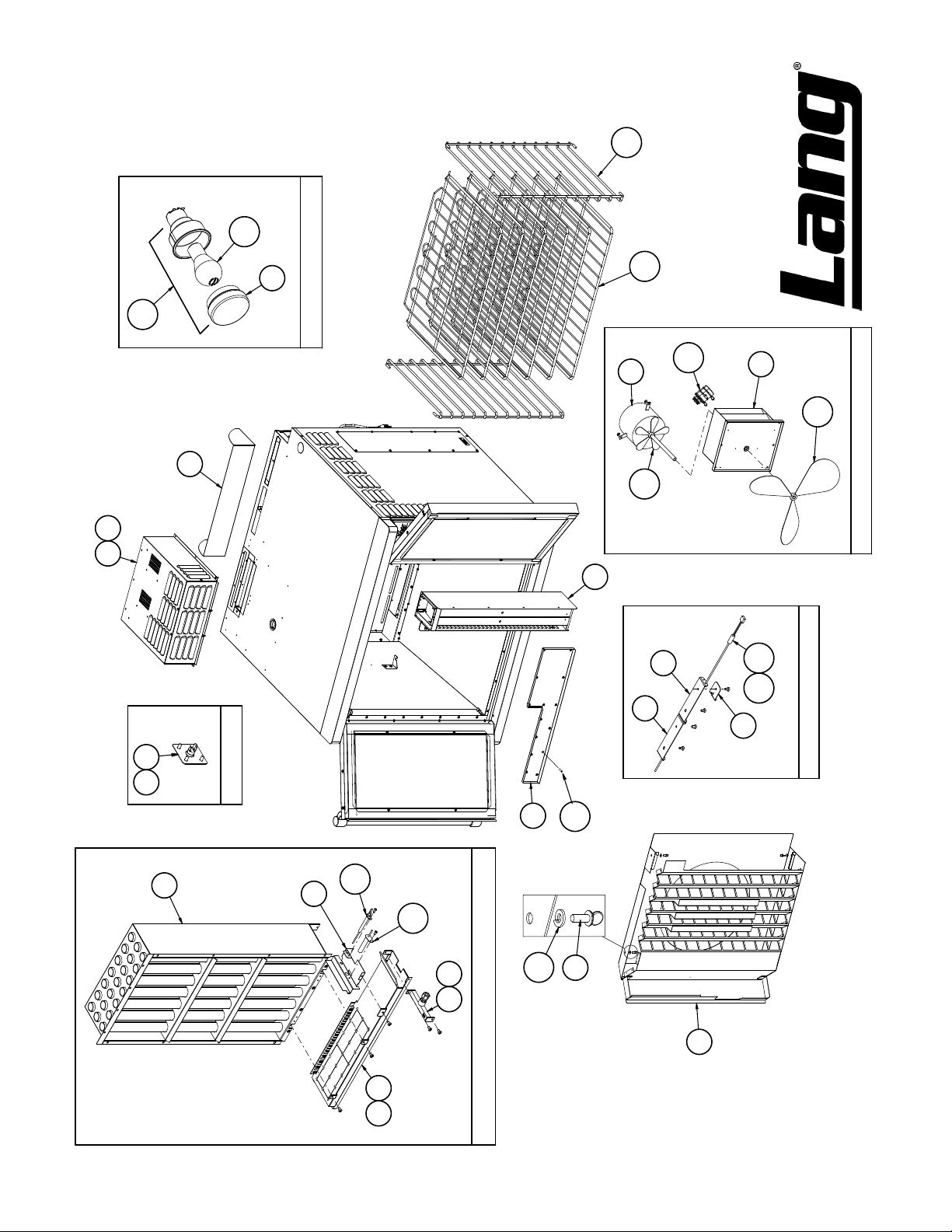
GCSF Main Interior Assy
NO REPRODUCTION OR DISCLOSURE OF ITS CONTENTS IS PERMITTED.
MODEL:
THIS DRAWING CONTAINS INFORMATION CONFIDENTIAL TO STAR MFG. INT'L. INC.
Page 29
113
24
79
104
129
71
31
117
30
115
IL1316 Rev. - 3/28/07
35
37
95
94
130
40
33
93
40
39
38
34
98
137
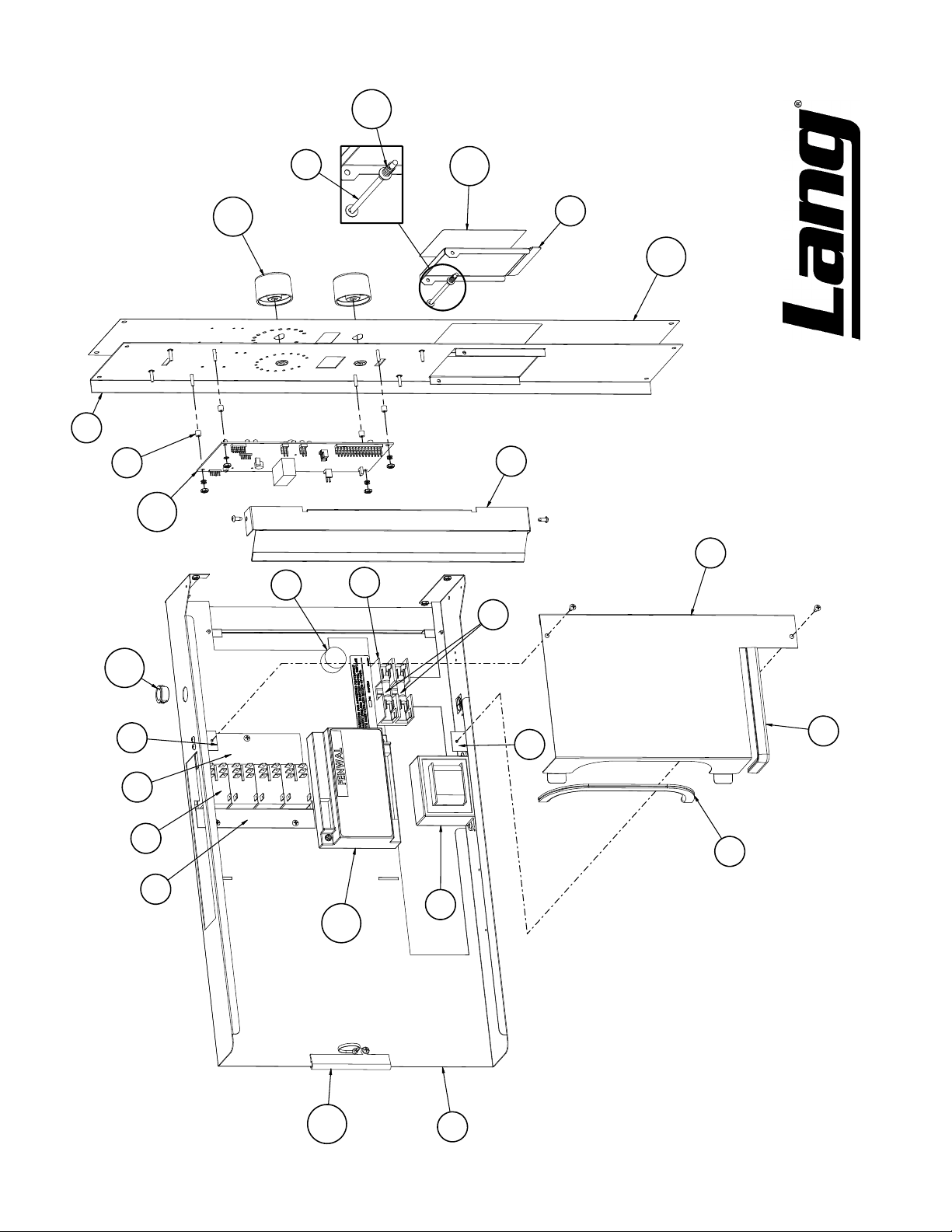
GCSF-ES Control Panel Assy (EnviroSTAR)
140
26
NO REPRODUCTION OR DISCLOSURE OF ITS CONTENTS IS PERMITTED.
MODEL:
THIS DRAWING CONTAINS INFORMATION CONFIDENTIAL TO STAR MFG. INT'L. INC.
Page 30
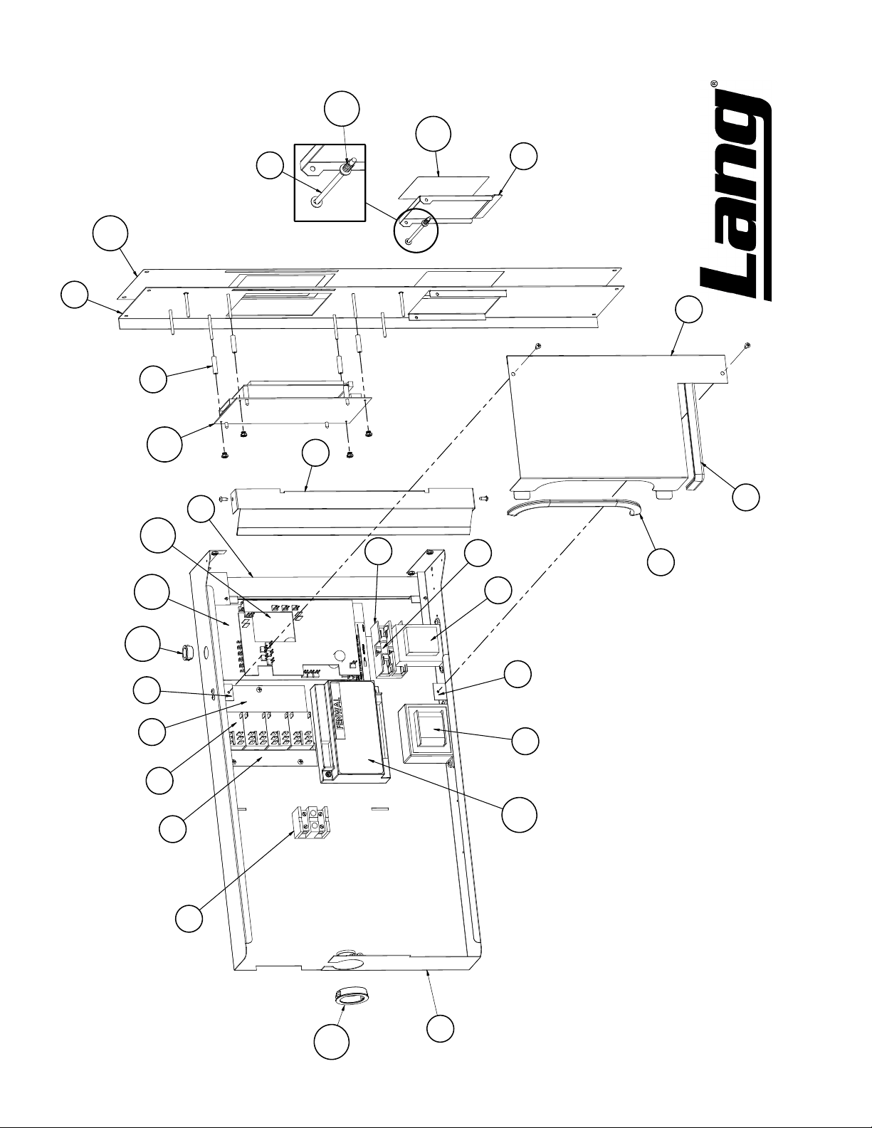
25
113
117
31
30
116
IL1315 Rev. - 3/28/07
37
80
103
105
130
40
33
93
102
34
36
35
95
94
39
38
97
40
98
137
91
131
27
GCSF-EZ Control Panel Assy (EnviroZONE)
NO REPRODUCTION OR DISCLOSURE OF ITS CONTENTS IS PERMITTED.
MODEL:
THIS DRAWING CONTAINS INFORMATION CONFIDENTIAL TO STAR MFG. INT'L. INC.
Page 31
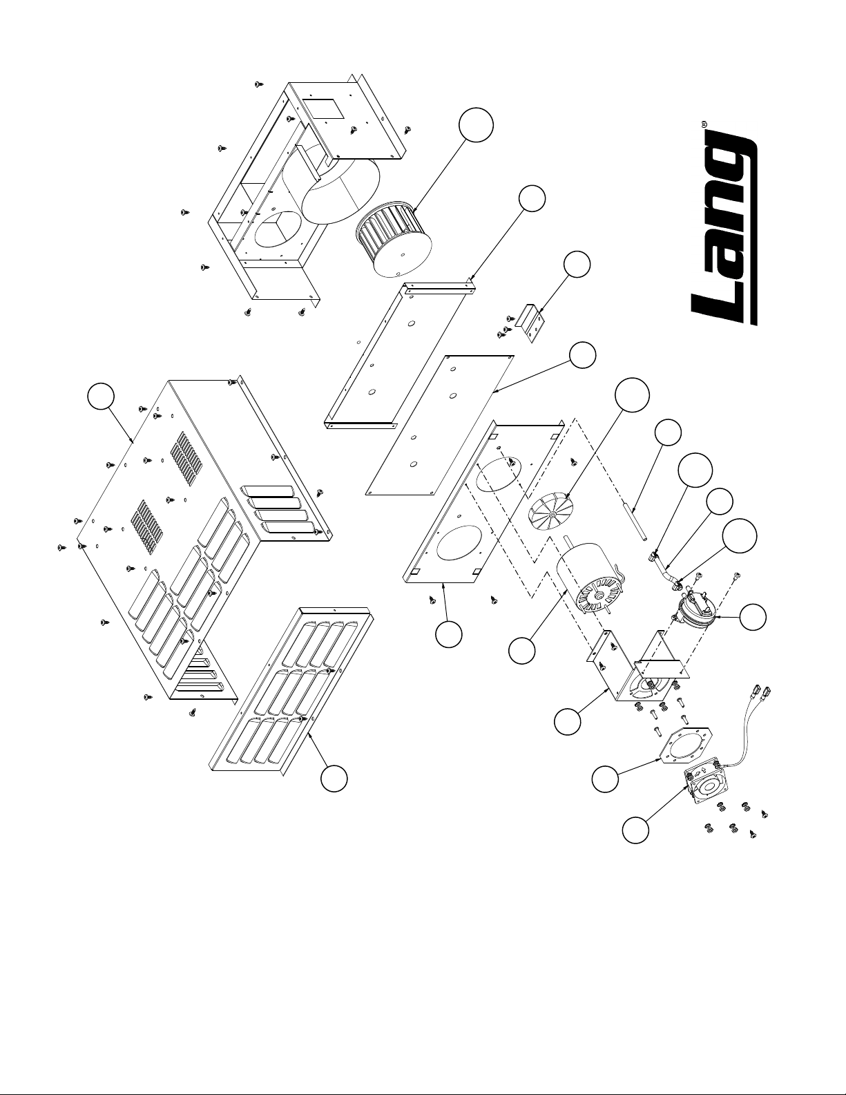
135
46
55
IL1317 Rev. - 3/27/07
47
51
52
134
53
136
54
136
88
48
83
49
50
84
GCSF Draft Inducer Assy
NO REPRODUCTION OR DISCLOSURE OF ITS CONTENTS IS PERMITTED.
MODEL:
THIS DRAWING CONTAINS INFORMATION CONFIDENTIAL TO STAR MFG. INT'L. INC.
Page 32
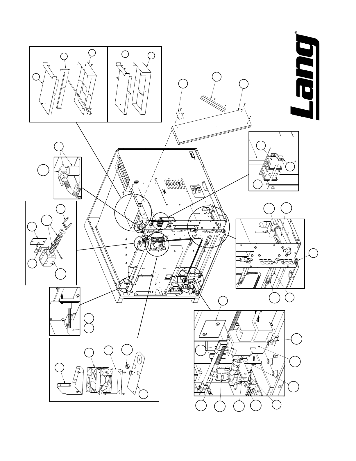
8
5
7
6
32
7
43
EnviroZone Only
EnviroStar Only
44
72
IL1319 Rev. - 3/28/07
67
67A
92
96
13
29
114
124
121
28
EnviroZone Only
127
56
109 108
81
57
130
EnviroZone Only
58
78
66
17
119
122
119
139
120
GCSF Below Skin Level Assy
118
123
126
123
10
NO REPRODUCTION OR DISCLOSURE OF ITS CONTENTS IS PERMITTED.
MODEL:
THIS DRAWING CONTAINS INFORMATION CONFIDENTIAL TO STAR MFG. INT'L. INC.
Page 33

Description
Per
Quantity
Part
Number
Fig
GCSF-ES, GCSF-EZ Gas Full Size Convection Oven Parts List
49 Q9-146-426-1 1 INDUCER MOTOR BRACKET ALL
50 Q9-146-426-2 1 INDUCER FAN ADAPTER PLATE ALL
No.
51 Q9-146-427-1 1 INDUCER COVER ALL
Description
52 Q9-146-428 1 INDUCER COVER FRONT ALL
53 Q9-146-430-1 1 INDUCER AIR FLOW SENSING ALL
54 Q9-146-431-1 1 AIR FLOW SENSING TUBE ALL
55 Q9-146-432 1 INDUCER HOLD DOWN CLIP ALL
56 Q9-146-490 1 CTRL PANEL COOLING FAN BRKT GCSF-EZ
57 Q9-146-491 1 CTRL PANEL COOLING FAN MOUNT GCSF-EZ
58 Q9-146-493 1 CTRL PANL FAN BTM DEFLECTOR GCSF-EZ
59 Q9-146-720-2 1 INTAKE COVER ASSY-OCG ALL
60 Q9-146-728 1 HEATR MODULE WELDMENT ASY ALL
62 Q9-146-729-2 1 BURNER ASSY -NAT / PROPANE GCSF
63 Q9-146-730 1 SQ. ORIFICE TUBE ASY - NG GCSF-NAT
64 Q9-146-730-2 1 SQ. ORIFICE TUBE ASY - GCSF-LP
65 Q9-146-736 1 MOTOR BRACKET WELD ALL
66 Q9-146-737-1 2 WATER INLET ASSY ALL
67 Q9-146-738 1 WATER INLET ASSY ALL
67A 2K-70101-04 1 BRAS TBE ELBW 3/8NPTM-3/8 ALL
68 Q9-146-740 1 STEAMER ASSY ALL
69 Q9-146-745 1 DOOR ASSY LH ALL
70 Q9-146-750 1 DOOR ASSY RH ALL
71 Q9-146-762 1 BUZZER ASSY ALL
72 Q9-146-765 1 STACKING VENT ASSY ALL
73 Q9-146-775-11 1 DRAFT INDUCER ASSY SINGLE ALL
74 Q9-146-775-21 1 DRAFT INDUCER ASSY DOUBLE ALL
75 Q9-146-776 1 BODY SIDE ASSY RH W/AVK ALL
76 Q9-146-778 1 BODY BACK W/AVKS ALL
77 2C-20112-03 4 SCRW THUMB 1/4-20X1/2 SS ALL
78 2C-20119-01 1 EYEBLTFORGD/SHLDR1/4-20X1 ALL
79 2A-20501-05 4 SPCR FBR 1/4 OD #6 ID 1/4 ALL
80 2A-20504-02 4 SPACER NYLON #6 1/4 X 1 GCSF-EZ
81 2U-30200-45 1 MTR W/FAN AXIAL 115VAC70C GCSF-EZ
Per
Quantity
82 2U-30200-68 1 MOTOR OCG 120V ALL
83 2U-30200-70 1 MOTOR OCG VENT FAN ALL
84 2U-30200-71 1 FAN AXIAL 60MMX30MM 115V ALL
85 2E-30301-19 1 SWT MIN. LEVER ACTUAT ALL
86 2E-30303-16 1 SWT TOG ON-ON BLK MOM ALL
87 2E-30303-26 1 SWITCH 3PDT GCSF-ES
2E-30303-27 1 SWT TOGGLE ON-ON 4PDT GCSF-EZ
88 2E-30308-08 1 AIR SWITCH .1 WC ALL
89 Q9-30401-30-2 1 SWT KIT STAT FXD 550 DEG ALL
NI = NOT ILLUSTRATED
Part
Number
Fig
No.
1 Q9-146-102-1 1 RIGHT REAR CORNER ALL
2 Q9-146-103-21 1 BODY TOP - OCG ALL
3 Q9-146-104 1 BODY LEFT SIDE ALL
4 Q9-146-105-01 1 RH SIDE ACCESS COVER ALL
6 Q9-146-126-1 1 BOTTOM POWER VENT E-S ALL
7 Q9-146-127 1 TOP POWER VENT ALL
9 Q9-146-149-1 1 BACKUP CONTROL BRACKET ALL
10 Q9-146-150 1 WATER SOLONOID BRACKET ALL
11 Q9-146-160 2 PROBE HOLDER ALL
12 Q9-146-161 1 PROBE CLAMP ALL
13 Q9-146-162 1 SERVICE ENTRANCE BOX ALL
14 Q9-146-163 1 SERVICE ENTRANCE COVER ALL
15 Q9-146-165-1 1 BURNER ACCESS COVER ALL
16 Q9-146-212 1 IGNITOR & SENSOR BRACKET ALL
17 Q9-146-230 1 GAS VALVE BRACKET ALL
18 Q9-146-316 2 DOOR GASKET SIDES ALL
19 Q9-146-317 1 DOOR GASKET TOP ALL
20 Q9-146-318 1 DOOR GASKET BOTTOM ALL
21 Q9-146-322 1 DOOR SWITCH BRACKET ALL
22 Q9-146-330 1 HINGE COVER TOP ALL
23 Q9-146-331 1 HINGE COVER BOTTOM ALL
24 Q9-146-350 1 CONTROL PANEL - ENVIROSTAR GCSF-ES
25 Q9-146-350-1 1 CONTROL PANEL - ENVIROZONE GCSF-EZ
26 Q9-146-351 1 COMPONENT MOUNT ENVIRO ALL
30 Q9-146-356 1 COVER CONTROL PANEL DOOR ALL
31 Q9-146-357 1 BACK UP DOOR HINGE ROD ALL
33 Q9-146-359 1 RELAY CLAMP ALL
34 Q9-146-360 1 RELAY CLAMP BASE ALL
35 Q9-146-361 1 PC BOARD HEAT SHIELD ALL
36 Q9-146-362 1 PC BOARD PROTECTOR ALL
37 Q9-146-363 1 COMPONENT WIRE COVER ALL
38 Q9-146-363-1 1 TRIMLOCK 8.750 ALL
39 Q9-146-363-2 1 TRIMLOCK 7.500 ALL
40 Q9-146-364 2 COMPONENT WIRE COVER CLIP ALL
41 Q9-146-404 2 STACKING CLIP ALL
42 Q9-146-405 1 VENT COVER ALL
43 Q9-146-408 1 VENT PASSTHROUGH UPPER ALL
44 Q9-146-409 1 REAR PANEL STANDOFF ANGLE ALL
45 Q9-146-413 1 ACCESS PANEL - MOTOR ALL
46 Q9-146-423-1 1 INDUCER INSULATION PLATE ALL
47 Q9-146-424-1 1 INDUCER INSULATION COVER ALL
48 Q9-146-425-1 1 INDUCER FAN BEZEL ALL
Rev. D 11/11/2013
Page 34

Description
Per
Quantity
Part
Number
Fig
GCSF-ES, GCSF-EZ Gas Full Size Convection Oven Parts List
128 Y9-70701-17-1 1 KNOB 450o B PHANTOM ALL
129 2R-70701-45-1 2 BKKNOB RED TOP 6MM W/D GCSF-ES
No.
130 2K-70801-04 3 SNAP BUSH 3/4 SB750-10 GCSF-ES
Description
130 2K-70801-04 5 SNAP BUSH 3/4 SB750-10 GCSF-EZ
131 2K-70801-08 1 SNAP BUSH 1 3/4 SB1750-22 ALL
132 2U-71500-16 1 FAN - NCO 16 IN ALL
133 2U-71500-17 1 FAN - NCO 6 IN ALL
134 2U-71500-18 1 FAN - OCG COOLING FAN ALL
135 2U-71500-19 1 BLOWER WHEEL OCG INDUCER ALL
136 2C-71700-03 1 HOSE CLAMP 1/2 ALL
137 PS-SK-W1353 1 KIT, SERVICE GCSF MODULE ALL
138 2J-80302-13 1 IGNITER 1325-1425'C - OCG ALL
139 2V-80505-18 1 GAS VALVE - OCG ALL
140 Q9-EH-502-1 1 TRIMLOCK 4 ALL
141 9Q-GCSF-IK-1 1 INSTALL KIT-SINGLE OVEN ALL
142 9Q-GCSF-IK-2 1 INSTALL KIT-DOUBLE OVEN ALL
143 2C-20204-02 4 WASHER SS 1/4 SPLIT LOCK ALL
144 2C-20109-15 14 SCRW PHD MS SS 10-32X1/2 ALL
NI 2P-73000-09 1 SPROCKET 5/8 BORE NO/KEY ALL
NI 2E-30500-09 1 TRM BLOCK 3 POLE SMALL 95 ALL
NI 2J-40301-50 4 SOCKET CONTACT FEMALE ALL
NI Q9-146-727 1 HEATER MODULE-NATURAL GCSF-NAT
NI Q9-146-727-2 1 HEATER MODULE-PROPANE GCSF-LP
NI Q9-146-730 1 SQUARE ORFICE TUBE ASSY-NAT GCSF-NAT
NI Q9-146-730-2 1 SQUARE ORFICE TUBE ASSY-LP GCSF-LP
INSTALLATION KIT
NI Q9-60101-96 1 SINGLE CONNECTION MANIFOLD KIT
NI PS-SK1463633 1 DRAFT INDUCER NOISE REDUCTION SERVICE KIT
NI PS-SK-W1352 1 GCSF SUBBERS / RELAY SERVICE KIT
Per
Quantity
NI = NOT ILLUSTRATED
Part
Number
Fig
No.
91 2E-30500-08 1 TRM BLOCK 2 POLE SMALL 95 GCSF-EZ
92 2E-30500-09 1 TRM BLOCK 3 POLE SMALL 95 ALL
93 2E-30701-05 4 CONTC 2POLE 30A 24VAC P & ALL
94 2E-30900-10 2 FUSE 15AMP 300V (SC-15) ALL
95 2E-30901-12 1 FUSE HOLDER 600V 2 POLE ALL
96 2E-31200-02 1 LUG GROUNDING UL APPROVED ALL
98 2E-31400-34 1 XFORMR 120-240/25.2VAC CT ALL
99 2S-31602-08-2 4 LMP GLBE SP FR31602-08@09 ALL
100 2S-31602-09 4 LAMP FIXTURE RANGE W/130V ALL
101 2S-31602-09-1 4 130V BULB {FOR 31602-09} ALL
102 2J-40102-25 1 DSPLY 302X240 DB170-001 GCSF-EZ
103 2J-40102-51 1 CIRBD FILTER GCSF-EZ
104 2J-40102-W64 1 CONTROL - OCE/OCG GCSF-ES
105 Q9-40102-70 1 MAIN BOARD, OCE/OCG GCSF-EZ
106 2E-40704-14 1 CAP 7.5 MFD 370VAC ALL
107 2E-41100-36 1 SENSOR FLAME PROBE OCG ALL
108 2E-41100-38 1 SENSOR TEMP ECSF/GCSF GCSF-ES
2E-41100-41 1 SENSOR TEMP ECSF/GCSF GCSF-EZ
110 2B-50200-103 2 RACK SLIDE OCE/OCG ALL
111 2B-50200-20 6 RACK ECCO/GCCO OVEN ALL
112 Q9-50312-02-1 2 DOOR CHAIN AND TURNBCKL ALL
113 2P-51001-19 1 SPRING SWT DR HINGE EHS ALL
114 2P-51001-38 1 SPRING VENT ALL
115 2M-60301-162 1 LABEL PANEL OCE/G ENVIROSTAR GCSF-ES
116 2M-60301-166 1 LABEL PANEL OCE/G ENVIROZONE GCSF-EZ
117 2M-60301-169 1 LABEL OCE ACCESS DR W/BUP ALL
118 2K-70101-03 1 BRASTBEELBOW 1/4NPT-3/8CC ALL
119 2K-70101-12 1 BRAS TBE ELBW 3/8CC-1/2 ALL
120 2K-70101-54 1 BRAS TBE UNION 3/8CCX1/4 ALL
121 2K-70302-36-1 1 PIPE NIPPLE 3/4NPT X 8BLK ALL
122 2K-70302-53 1 PIPE COUPLING 3/8X1-3/16 ALL
123 2K-70303-03 1 PIPE COUPLING 1/4 NPT ALL
124 2K-70305-05 1 PIPE 90o ELBOW 3/4 BLK ALL
125 2V-70402-07 1 VALVE MANUAL GAS 1/2X1/2 ALL
126 2V-70403-05 1 SOLENOID WATER ALL
Rev. D 4/10/2015
Page 35

Page 36

STAR INTERNATIONAL HOLDINGS INC. COMPANY
Star - Holman - Lang - Wells - Bloomeld - Toastmaster
10 Sunnen Drive, St. Louis, MO 63143 U.S.A.
(314) 678-6303
www.star-mfg.com
 Loading...