

Page 1
SHIPBOARD ELECTRIC
CONVECTION OVEN
ECOD-AT, ECODL-AT
ECOF-AT, ECOFL-AT
Installation and
Operation
Instructions
2M-W483 Rev. B 6/14/07
ECOF-AT
1
Page 2

SAFETY SYMBOL
Using any part other than genuine Star factory supplied parts relieves the
manufacturer of all liability.
Star reserves the right to change speci¿ cations and product design without
notice. Such revisions do not entitle the buyer to corresponding changes,
improvements, additions or replacements for previously purchased
equipment.
Due to periodic changes in designs, methods, procedures, policies and
regulations, the speci¿ cations contained in this sheet are subject to change
without notice. While Star Manufacturing exercises good faith efforts to provide
information that is accurate, we are not responsible for errors or omissions
in information provided or conclusions reached as a result of using the
speci¿ cations. By using the information provided, the user assumes all risks in
connection with such use.
These symbols are intended to alert the user to the presence of
important operating and maintenance instructions in the manual
accompanying the appliance.
RETAIN THIS MANUAL FOR FUTURE REFERENCE
NOTICE
MAINTENANCE AND REPAIRS
Contact your local authorized service agent for service or required maintenance. Please record
the model number, serial number, voltage and purchase date in the area below and have it
ready when you call to ensure a faster service.
Model No.
Serial No.
Voltage
Purchase Date
Authorized Service Agent
Reference the listing provided with the unit
or
for an updated listing go to:
Website: www.star-mfg.com
E-mail Service@star-mfg.com
Telephone: (800) 807-9054 Local (314) 781-2777
The Star Service Help Desk
Business 8:00 am to 4:30 p.m. Central Standard Time
Hours:
Telephone: (800) 807-9054 Local (314) 781-2777
Fax: (800) 396-2677 Local (314) 781-2714
E-mail Parts@star-mfg.com
Service@star-mfg.com
Warranty@star-mfg.com
Website: www.star-mfg.com
Mailing Address: Star Manufacturing International Inc.
10 Sunnen Drive
St. Louis, MO 63143
U.S.A
2
Page 3
Chapter . . . . . . . . . . . . . . . . . . . . . . . . . . . . . . . . . . . . . . . . . .Page
1. Table of Contents . . . . . . . . . . . . . . . . . . . . . . . . . . . . . . . . . .3
2. List of Illustrations . . . . . . . . . . . . . . . . . . . . . . . . . . . . . . . . . .3
3. Specifi cations . . . . . . . . . . . . . . . . . . . . . . . . . . . . . . . . . . . . . 3
4. Equipment Description . . . . . . . . . . . . . . . . . . . . . . . . . . . . . .4
5. Installation . . . . . . . . . . . . . . . . . . . . . . . . . . . . . . . . . . . . . . . . 5
6. Operation . . . . . . . . . . . . . . . . . . . . . . . . . . . . . . . . . . . . . . . . 7
7. Maintenance & Troubleshooting Procedures . . . . . . . . . . . . .8
8. Wiring Diagrams . . . . . . . . . . . . . . . . . . . . . . . . . . . . . . . . . . .11
9. Parts List . . . . . . . . . . . . . . . . . . . . . . . . . . . . . . . . . . . . . . . . .15, 17, 19, 21, 23
Fig# Title of Illustraion . . . . . . . . . . . . . . . . . . . . . . . . . . . . . . . . .Page #
1. Picture of Oven . . . . . . . . . . . . . . . . . . . . . . . . . . . . . . . . . . . .Cover
2. Specifi cations . . . . . . . . . . . . . . . . . . . . . . . . . . . . . . . . . . . . . 3
3. Leg Installation . . . . . . . . . . . . . . . . . . . . . . . . . . . . . . . . . . . .6
4. Stacking Instructions . . . . . . . . . . . . . . . . . . . . . . . . . . . . . . . . 6
5. Wiring Diagram 208/240 VAC . . . . . . . . . . . . . . . . . . . . . . . . . 11
6. Wiring Diagram 440 VAC . . . . . . . . . . . . . . . . . . . . . . . . . . . .12
7. Exploded View . . . . . . . . . . . . . . . . . . . . . . . . . . . . . . . . . . . . 14, 16, 18, 20, 22
NOTICE: Service on this, or any other, LANG appliance must be
Table of Contents
List of Illustrations
performed by qualifi ed personnel only. Consult your LANG
authorized service agent directory or call the factory at
1-800-807-9054, or WWW.STAR-MFG.COM for the service agent
nearest you.
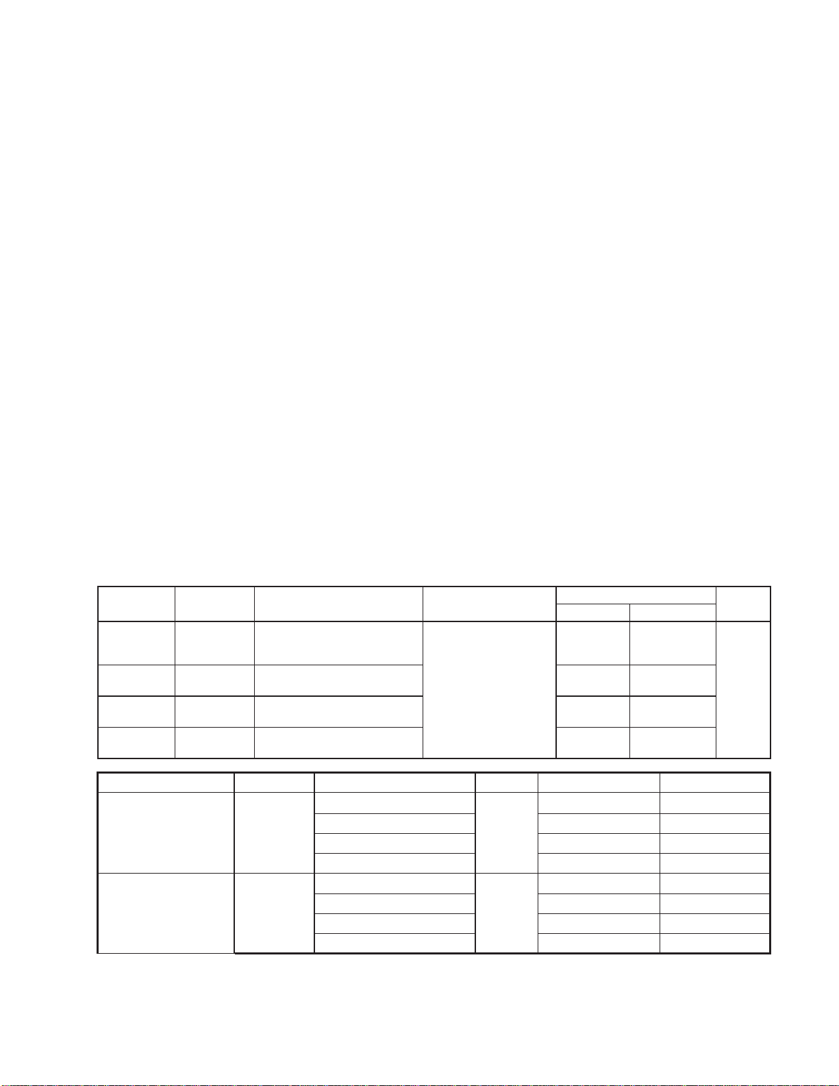
SPECIFICATIONS:
Star Model Lang Model Height x Width x Depth
ECOD-AT ECO-6M
ECOF-AT ECO-7M
ECOD-AT
ECODL-AT
ECOF-AT
ECOFL-AT
Star Model Lang Model Volts AC - Hz Total kW Amps - 3Ph Amps - 1Ph
ECO-8M
ECO-9M
25.0” x 38.0” x 45.2”
635mm x 966mm x 1148mm
25.0” x 38.0” x 38.2”
635mm x 966mm x 970mm
50.0” x 38.0” x 45.2”
1270mm x 966mm x 1148mm
50.0” x 38.0” x 38.2”
1270mm x 966mm x 970mm
Clearance from
conbustible surface
Side: 6” (153mm)
Back: 6” (153mm)
Floor: 6” (153mm)
Actual Shipping
380 lbs.
173 kg
360 lbs.
164 kg.
820 lbs.
373 kg
780 lbs.
355 kg
208 - 50/60
Single Stack
ECOD-AT
ECOF-AT
ECO-6M
ECO-7M
240 - 50/60 28.8 48.6
440 - 50/60 17.1 N/A
11.7
480 - 50/60 16.1 N/A
208 - 50/60
Double Stack
ECOD-AT, ECODL-AT
ECOF-AT, ECOFL-AT
ECO-8M
ECO-9M
240 - 50/60 57.7 97.2
440 - 50/60 34.2 N/A
23.3
480 - 50/60 32.2 N/A
Weight
430 lbs.
195 kg
410 lbs.
186 kg
870 lbs
395 kg
830 lbs.
377 kg
37.1 56.1
74.2 112.1
Freight
Class
70
Figure 2
3
Page 4

EQUIPMENT DESCRIPTION
INTRODUCTION
This manual contains the necessary information to install, operate, maintain, and service the Lang model
ECO convection ovens.
Replacement parts should be genuine Lang parts. Failure to use genuine Lang replacement parts may
result in malfunction of the appliance or possible injury to the contractor or service technician.
PURPOSE AND FUNCTION
Convection ovens constantly circulate air over the product. This removes a layer of moisture and cool
air from around the product. This allows heat to penetrate the product more quickly. Cooking times are
shortened and cooking temperatures are reduced.
CAPABILITIES
This convection oven is suitable for cooking all types of products requiring baking or roasting.
ENVIRONMENTAL REQUIREMENTS
The following minimum spacing from combustible surfaces must be maintained: Sides – 2 inches, Back
– 2 inches
ITEMS FURNISHED (Listed by Model Number)
SINGLE STACKED UNITS
ECOD-AT
ECO-6 or ECO-6M (Previouse Model)
1 ea. Oven, Type I, Size 2
4 ea. Legs
16 ea. 3/8 – 16 x 5/8 Bolts (For mounting legs)
16 ea. 3/8 – 16 Hex Nuts (For mounting legs)
32 ea. Washers (For mounting legs)
2 ea. Rack Slides, Extra Deep
5 ea. Racks, Extra Deep
2 ea. Manuals, Technical
ECOD-AT or ECOF-AT
ECO-7 or ECO-7M (Previouse Model)
1 ea. Oven, Type I, Size 1
4 ea. Legs
16 ea. 3/8 – 16 x 5/8 Bolts (For mounting legs)
16 ea. 3/8 – 16 Hex Nuts (For mounting legs)
32 ea. Washers (For mounting legs)
2 ea. Rack Slides, Standard Depth
5 ea. Racks, Standard Depth
2 ea. Manuals, Technical
DOUBLE STACKED UNITS
ECOD-AT, ECODL-AT or ECOF-AT, ECOFL-AT
ECO-8 or ECO-8M (Previouse Model)
2 ea. Oven, Type II, Size 2
4 ea. Legs
16 ea. 3/8 – 16 x 5/8 Bolts (For mounting legs)
16 ea. 3/8 – 16 Hex Nuts (For mounting legs)
32 ea. Washers (For mounting legs)
4 ea. Rack Slides, Extra Deep
10 ea. Racks, Extra Deep
2 ea. Manuals, Technical
1 ea. Stacking Kit
ECOD-AT, ECODL-AT or ECOF-AT, ECOFL-AT
ECO-9 or ECO-9M (Previouse Model)
2 ea. Oven, Type II, Size 1
4 ea. Legs
16 ea. 3/8 – 16 x 5/8 Bolts (For mounting legs)
16 ea. 3/8 – 16 Hex Nuts (For mounting legs)
32 ea. Washers (For mounting legs)
4 ea. Rack Slides, Standard Depth
10 ea. Racks, Standard Depth
2 ea. Manuals, Technical
1 ea. Stacking Kit
4
Page 5

ITEMS REQUIRED
An adequate supply of wire suitable for the loads and application specifi ed on the data sheet must be
provided. The data sheet is on Page 4 of this manual.
TOOLS AND TEST EQUIPMENT REQUIRED
For Installation:
1 set – Open End Wrenches
1 – Flat Blade Screwdriver
1 – Phillips Screwdriver
1 – Wire Cutter/Stripper
1 – AMP Probe
1 – Voltmeter
1 – Drill
4 – #27 Drill Bits
For Service: All of the above plus –
1 – Needle Nose Pliers
1 – Crimping Pliers
1 – Allen Wrench Set
1 – Temperature Meter
1 – Very Small Flat Blade Screwdriver
1 – #10 Square Drive Screwdriver
INSTALLATION
CAUTION: THE OVEN IS EXTREMELY HEAVY. FOR SAFE HANDLING,
INSTALLER SHOULD OBTAIN HELP AS NEEDED, OR EMPLOY
APPROPRIATE MATERIALS HANDLING EQUIPMENT (SUCH AS
A FORKLIFT, DOLLY, OR PALLET JACK) TO REMOVE THE UNIT
FROM THE SKID AND MOVE IT TO THE PLACE OF
INSTALLATION.
CAUTION: ANY STAND, COUNTER OR OTHER DEVICE ON WHICH OVEN
WILL BE LOCATED MUST BE DESIGNED TO SUPPORT THE
WEIGHT OF THE OVEN(S).
CAUTION: SHIPPING STRAPS ARE UNDER TENSION AND CAN SNAP BACK
WHEN CUT.
DANGER: THIS APPLIANCE MUST BE GROUNDED AT THE TERMINAL
PROVIDED. FAILURE TO GROUND THE APPLIANCE COULD
RESULT IN ELECTROCUTION AND DEATH.
WARNING: INSTALLATION OF THE UNIT MUST BE DONE BY PERSONNEL
QUALIFIED TO WORK WITH ELECTRICITY AND PLUMBING.
IMPROPER INSTALLATION CAN CAUSE INJURY TO PERSONNEL
AND/OR DAMAGE TO EQUIPMENT. UNIT MUST BE INSTALLED IN
ACCORDANCE WITH ALL APPLICABLE CODES.
NOTICE: The data plate is located on the door of the oven. The oven
voltage, wattage, serial number, wire size, and clearance
specifi cations are on the data plate. This information should be
carefully read and understood before proceeding with the
installation.
5
Page 6

NOTICE: The installation of any components such as a vent hood, grease
extractors, fi re extinguisher systems, must conform to their
applicable National, State and locally recognized installation
standards.
INSTALLATION
INSPECTION AND INSTALLATION
Upon receipt of the oven(s) any damage should be noted on the Bill of Lading and countersigned by the
carrier. If concealed damage is discovered the carrier should be notifi ed. All claims must be fi led with
the carrier.
Move the crate(s) containing the oven(s) as close to the place of installation as possible before removing
the protective crating. Uncrate the oven(s) and move them as close as practical to the fi nal installation
site.
Bolt the legs to the bottom oven, (See fi gure #2). Use the 3/8 – 16 x 5/8 Bolts, Hex Nuts and Washers
provided. There are pre-punched holes provided in the legs and oven bottom to aid in leg installation.
Now the oven can be set upright in or near its fi nal position.
SINGLE OVENS:
Connect power throught the knockout on the
bottom of the unit.
The oven can be placed in its fi nal position
and leveled. The oven is ready for initial startup procedures now. (See page 7)
STACKED OVENS:
Be careful to route the power supply wire
between the two ovens using the holes
provided. Do not pinch or cut the supply wires
when stacking the ovens. Use the stacking kit
provided to secure the top oven to the bottom
oven.
The stacking kit contains four (4) identical
corner braces, one brace goes on each corner.
Drill pilot holes for the mounting screws using
the pre-punched holes as a guide. Secure the
top oven to the bottom oven with the sheet
metal screws provided. (See fi gure #3)
Connect the power supply leads from the top
oven to the power supply leads of the bottom oven and incoming power per the wiring
diagram on Page 11 or 12.
Oven Bottom
Nut 3/8 - 16 Hex
Flange
Leg
Figure 2, Bolting Legs to bottom oven
Top Oven
Lock Washer
Washer
Bolt 3/8 - 16 x 5/8
Corner Brace
IL1321
Now the bottom oven can be connected to the
incoming power supply through the knockout provided in the bottom of the oven. Be
sure the power supply voltage matches the
voltage specifi ed on the nameplate located on
the front of the oven! Then the oven can be
placed in its fi nal position and leveled. The
oven is ready for initial start-up procedures
now. See page 7.
Bottom Oven
IL1322
Figure 3, Securing the top & bottom ovens together.
6
Page 7

OPERATING INSTRUCTIONS
NOTICE: During the fi rst few hours of operation you may notice a small
amount of smoke coming off the oven, and a faint odor from the
smoke. This is normal for a new oven and will disappear after the
fi rst few hours of use.
CAUTION: ALWAYS KEEP THE AREA NEAR THE APPLIANCE FREE FROM
COMBUSTIBLE MATERIALS.
CAUTION: KEEP FLOOR IN FRONT OF EQUIPMENT CLEAN AND DRY. IF
SPILLS OCCUR, CLEAN IMMEDIATELY, TO AVOID THE DANGER
OF SLIPS OR FALLS.
Each oven has the following controls:
Vent – Pull to Open, Push to close.
Timer – Adjust to desired setting.
Temperature – Turn to desired cooking temperature.
Power Switch – Pull up to turn oven ON, push down to turn oven OFF.
Light Switch – Pull up to turn oven light ON, release and oven light goes out automatically.
Motor Speed Switch – Pull up for High Speed, push down for low speed.
INITIAL START-UP
Set oven(s) at 350°F and allow oven to operate empty for 3 hours, prior to initial use.
NORMAL OPERATION
Turn the Power Switch On, turn to the desired temperature and select motor speed. (Hi or Low)
7
Page 8

MAINTENANCE
Wash the stainless interior & exterior often with a solution of hot water and mild detergent to prevent grease
build-up and preserve the oven’s appearance. The oven racks, slides and stainless steel oven liners are
removable for easier cleaning of the oven interior.
NOTE: Wipe up spillage as soon as possible. Never use scouring powder. It is diffi cult to remove completely
and a residue build-up can damage the oven.
WARNING: KEEP WATER AND SOLUTIONS OUT OF CONTROLS. NEVER
SPRAY OR HOSE CONTROL CONSOLE, ELECTRICAL
CONNECTIONS, ETC.
CAUTION: MOST CLEANERS ARE HARMFUL TO THE SKIN, EYES,
MUCOUS MEMBRANES AND CLOTHING. PRECAUTIONS
SHOULD BE TAKEN TO WEAR RUBBER GLOVES, GOGGLES OR
FACE SHIELD AND PROTECTIVE CLOTHING. CAREFULLY READ
THE WARNING AND FOLLOW THE DIRECTIONS ON THE LABEL
OF THE CLEANER TO BE USED.
NOTICE: Service on this, or any other, LANG appliance must be performed
by qualifi ed personnel only. Consult your authorized service
station directory or call the factory at 1-800-224-LANG (5264), or
WWW.LANGWORLD.COM For the service station nearest you.
WARNING: BOTH HIGH AND LOW VOLTAGES ARE PRESENT INSIDE THIS
APPLIANCE WHEN THE UNIT IS PLUGGED/WIRED INTO A LIVE
RECEPTACLE. BEFORE REPLACING ANY PARTS, DISCONNECT
THE UNIT FROM THE ELECTRIC POWER SUPPLY.
CAUTION: USE OF ANY REPLACEMENT PARTS OTHER THAN THOSE SUP-
PLIED BY LANG OR THEIR AUTHORIZED DISTRIBUTORS CAN
CAUSE BODILY INJURY TO THE OPERATOR AND DAMAGE TO
THE EQUIPMENT AND WILL VOID ALL WARRANTIES.
TROUBLESHOOTING GUIDE
SYMPTOM PROBLEM REMEDY
Internal Circuit Breakers Off Turn on
Oven will not turn on
Power Supply Circuit Breakers Trip
Internal circuit breakers trip Supply voltage & oven voltage do not match change voltage to match oven
Oven takes to long to bake and will not
maintain temperature
Power supply circuit breakers off Turn on
Improperly Phased Phase per wiring diagram
Fuse Open Change fuses
Supply circuit breakers of insuffi cient size Install proper size breakers
Supply voltage & oven voltage do not match change voltage to match oven
Improperly Phased
Phase oven to match power
supply per wiring diagram
8
Page 9

MAINTENANCE and TROUBLESHOOTING CONT’D
PERFORMANCE AND INSPECTION
A periodic check of thermostat calibration should be performed. To check oven calibration attach a
thermocouple to the mid-point of the thermostat bulb in the oven cavity . Turn the temperature dial to 350°F
and turn the oven ON. Wait approximately 20 minutes until the oven temperature has stabilized. If the
average of the ON and OFF thermostat readings is within 10°F of 350°F the oven is in calibration. If not,
remove the temperature knob and turn the small screw in the middle until oven is in calibration. Replace
the knob and the oven is ready for normal operation.
MAJOR COMPONENT DISASSEMBLY, REPAIR, REPLACEMENT & REASSEMBLY
(Refer to fi gure #4, page 22)
THERMOSTAT, CONTACTORS (RELAYS), SWITCHES
These parts are located behind the control panel assembly on the right hand side of each oven. Remove
the screws attaching the control panel to the front of the oven. Slowly pull out the control panel until the
component requiring replacement is accessible.
THERMOSTAT REPLACEMENT:
Inside the oven cavity remove the retaining clips holding the thermostat-sensing bulb in place. Feed the
bulb through the oven wall into the control panel area. Remove the wires attached to the thermostat
terminals. Remember the terminal each wire was on and attach the wires to the same terminal on the
new thermostat. Remove the screws holding the old thermostat to the front of the control panel. Discard
old thermostat. Mount the new thermostat to the control panel, carefully feed the sensing bulb through
the oven wall, and reattach the sensing bulb to the oven side using the retaining clips removed earlier.
Close control compartment. Restore power to oven. Refer to the “Performance and Inspection” section
to verify proper operation of the new thermostat.
ELEMENT REPLACEMENT:
The element is located inside the oven cavity. To replace the element, remove the baffl e at the back
of the oven. This will expose the elements to plain view and allow easy access. Remove the element
mounting screws located near the top of the oven. Gently , pull the element into the oven cavity. There is
enough wire connected to the element to allow easy access to the terminals located behind the element
mounting plate. Move each wore from the existing terminal to the corresponding terminal on the new
element. DO NOT mix up these wires! After all wires are transferred to the new element, feed the wire
back through the access hole in the back of the oven and attach the element to the oven wall with the
screws removed earlier. Replace the baffl e. Refer to the “Initial Start-up” section to restore the oven to
proper operation.
CONTACTOR (RELAY), SWITCH REPLACEMENT:
Pull out control panel as previously outlined. Remove the wires from the contactor or switch being changed.
Place those wires on the corresponding terminal of the new part. Remove old part and mount new part
with wires attached in the spot where the old part used to be. Reinstall the control panel, restore power
to the oven. Turn oven on, set thermostat to 200°F and allow oven to cycle 3 times or until the technician
is satisfi ed with the proper operation of the oven.
BLOWER WHEEL REPLACEMENT:
The blower wheel is located inside the oven cavity. To replace the blower wheel, remove the baffl e at
the back of the oven. This will expose the blower wheel to plain view and allow easy access. Loosen
the two (2) set screws holding the blower wheel onto the motor shaft. Using a three-fi nger blower wheel
puller, grasp the puller ring with all three fi ngers and tighten the puller until the blower wheel hub clears
the motor shaft. Place new blower wheel on the motor shaft and position exactly 5/8” from the oven back
motor plate. Tighten the set screw positioned over the fl at on the motor shaft. Spin the fan to make sure
it spins straight. Tighten the second set screw and re-tighten the fi rst set screw. Replace the baffl e. The
oven is now ready to re-start.
9
Page 10

MAINTENANCE and TROUBLESHOOTING CONT’D
MOTOR REPLACEMENT:
The motor is located inside the oven cavity. To replace the motor, remove the baffl e at the back of the
oven. This will expose the blower wheel and motor shaft to plain view and allow easy access. Remove
the blower wheel as described in “BLOWER WHEEL REPLACEMENT”. Next, remove the bolts holding
the motor plate to the back wall of the oven cavity . Gently pull the motor forward and lay on the bottom of
the oven cavity . Mark the wires so they can be placed on the same terminals of the new motor. Remove
the motor wires. Remove the motor from the oven. Remove the motor mounting bolts, remove the old
motor and replace with the new one. Reveres the above steps to remount the motor and see “BLOWER
WHEEL REPLACEMENT” for proper re-installation of the blower wheel.
TRANSFORMER REPLACMENT:
Pull out control panel as previously outlined. Mark the wires attached to the transformer. Remove the wires.
Remove the screws holding the transformer to the control panel. Install the new transformer. Reconnect
the wires making sure they are attached to the same terminals as on the original transformer. Reinstall
the control panel, restore power to the oven. The oven is now ready for normal operation.
MICROSWITCH REPLACEMENT:
Open the oven doors and remove the screws from the micro switch cover located below the doors. Remove
the micro switch cover. Remove the two (2) small screws (6/32) holding the micro switch to its’ mount.
Mark the wires attached to the micro switch, then remove the wires. Attach the wires to the new micro
switch. Mount the micro switch with the two 6/32 screws. Adjust the micro switch arm for proper switch
actuation. Replace cover and restart oven.
10
Page 11

Figure 5
11
Page 12

Figure 6
12
Page 13

2
1
8
3
4
5
8
11
SEE DETAIL B
6
7
9
10
SEE DETAIL A
Model:
ECOF-AT1M Electric Marine Convection Oven
ECO-7M Electric Marine Convection Oven
14
SK2257 Rev. - 6/12/07
Page 14

PARTS LIST June 15, 2007, Rev B
Model No: ECOD-AT, ECODL-AT, ECOF-AT, ECOFL-AT
SHIPBOARD ELECTRIC CONVECTION OVEN
Key
Number
1 Q9-ECO-471 1 TOP-TOP DECK ECOF
Q9-ECO-472 1 TOP-BOTTOM DECK ECOFL
Q9-ECO-477 1 TOP-TOP-DECK DEEP OVEN ECOD
Q9-ECO-478 1 TOP-BOTTOM DECK DEEP ECODL
Q9-ECO-471-1 1 TOP FRONT - TOP DECK - HATCHABLE
2 Q9-ECO-471-2 1 TOP REAR - TOP DECK - SUB HATCHABLE
3 2P-70901-01 1 PLG BTN BLKPLSTC 1DP-1000 ECOD-AT-440G, ECODL-AT440M, ECOFL-AT208M,
ECOFL-AT440M
2P-70901-01 2 PLG BTN BLKPLSTC 1DP-1000 ECOF-AT-480M, ECOD-AT-480M
4 Q9-ECO-437 1 DAMPER PIVOT ALL
5 Q9-ECO-446 1 DAMPER ROD A ECOF
Q9-ECO-461 1 DAMPER ROD A - DEEP ECOD
6 2C-20103-02 2 SCRW SM PLT 10 X .5 PHLSL HATCHABLE
7 Q9-ECO-479-1 1 BTM COVER BTM DECK ONLY - HATCHABLE
8 Q9-ECO-177 1 BODY WRAP ASSY ECOF
Q9-ECO-177-1 1 BODY WRAP DEEP ASSY ECOD
9 Q9-ECO-196-1 1 FRONT ASSY - SUB ALL
10 Q9-ECO-203 1 SWITCH DOOR ASSY ALL
11 2R-70701-25 1 KNOB DAMPER BLACK PLAIN ALL
RACKS
NI 2B-50200-20 5 RACK ECCO/GCCO OVEN ECOF
NI 2B-50200-31 5 RACK ECO DEEP OVEN ONLY ECOD
NI 2B-50200-32 2 RACK SLIDE 5 POS ECO OVEN ECOF
NI 2B-50200-33 2 RACK SLIDE 5 POS ECO DEEP ECOD
Part
Number
Qty
Per
Description
1
IMPORTANT: WHEN ORDERING, SPECIFY VOLTAGE OR TYPE GAS DESIRED PAGE
2
INCLUDE MODEL AND SERIAL NUMBER OF
Some items are included for illustrative purposes only and in certain instances may not be available.
Star Manufacturing International, Inc.
15
Page 15

Front
12
13
14
15
16
17
SEE DETAIL
C
Model:
ECOF-AT1M Electric Marine Convection Oven
ECO-7M Electric Marine Convection Oven
SK2258 Rev. - 6/12/07
16
Page 16

PARTS LIST June 15, 2007, Rev B
Model No: ECOD-AT, ECODL-AT, ECOF-AT, ECOFL-AT
SHIPBOARD ELECTRIC CONVECTION OVEN
Key
Number
12 Q9-ECO-423 VENTS ASSY ALL
13 Q9-ECO-435 VENT CAP - MILITARY ALL
14 Q9-ECO-449 1 DAMPER ROD B ASSY ALL
15 Q9-ECO-391 1 MOTOR MOUNT ASSY 440/480V 440V/480V
Q9-ECO-391-1 1 MOTOT MOUNT ASSY 208V 208V
16 Q9-ECO-172 1 REAR FIREWALL ASSY ALL
17 Q9-ECO-184 1 BODY BACK ALL
ELEMENTS
ni 2N-11090-18 1 ELMNT ECCO 480V 11KW 480V
ni 2N-11090-30 1 ELE 415 440V11KW 440V
ni 2N-11090-16 1 ELE ECCO OVN 208/240V 11KW 208V
Part
Number
Qty
Per
Description
1
IMPORTANT: WHEN ORDERING, SPECIFY VOLTAGE OR TYPE GAS DESIRED PAGE
2
INCLUDE MODEL AND SERIAL NUMBER OF
Some items are included for illustrative purposes only and in certain instances may not be available.
Star Manufacturing International, Inc.
17
Page 17

44
33
32
55
53
45
SEE DETAIL D
37
35
34
33
39
38
36
48
49
41
39
43
47
46
42
41
40
54
53
55
52
61
60
59
58
51
56
57
62
10
49
18
51
50
DETAIL A
Typical Door Assy
SK2260
Page 18

PARTS LIST June 15, 2007, Rev B
Model No: ECOD-AT, ECODL-AT, ECOF-AT, ECOFL-AT
SHIPBOARD ELECTRIC CONVECTION OVEN
Key
Number
32 2C-20109-25 4 SCRW S/S 10-32 X 3/4 T/H ALL
33 2C-20201-07 4 WSHR FLT 1/4 SAE PLTD ALL
34 2C-20301-29 4 NUT HEX ACORN 1/4-20 S/S ALL
35 2C-20102-04 4 SCRW PHD ST 8-32X.5 PLTD ALL
36 Q9-ECO-595 2 ECO DOOR HANDLE ALL
37 2R-50800-91 2 DOOR HANDLE ALL
38 Q9-ECO-200-3 1 DOOR CATCH ASSY - SUB ALL
39 2C-20109-04 2 SCRW THD MS SS 10-32X3/8 ALL
40 2C-20115-01 10 SCRW S/S 8-32X1/2 P/H S/T ALL
41 Q9-ECO-507 4 HINGE PIN WELD - ECO ALL
42 2C-20109-15 8 SCRW PHD MS SS 10-32X1/2 ALL
43 Q9-ECO-557 4 HANDLE SPACER ALL
44 2R-70602-03 2 CATCH DOOR MAGNET 3 PC ALL
45 Q9-ECO-533 2 MAGNET BACKER ALL
46 2C-20101-10 4 SCRW THD MS 1/4-20X2 1/4 ALL
47 2C-20201-07 4 WSHR FLT 1/4 SAE PLTD ALL
48 Q9-ECO-563 4 RETAINER ALL
49 2C-20306-03 10 AVK CAD 10-32 1ST GRP ALL
50 Q9-ECO-572 1 RH DOOR VANE ASSY S/S ALL
50 Q9-ECO-584 1 LH DOOR VANE ASSY S/S ALL
51 2C-20103-02 AR SCRW SM PLT 10 X .5 PHLSL ALL
52 Q9-ECO-777-1 2 SWITCH CAM ASSY - 1/2 ALL
53 2C-20109-30 8 SCRW MS SS 10-32 X .75 PH ALL
54 2P-70201-19 4 BRNZBRFLN1/2IDX5/8ODX3/8 ALL
55 Q9-ECO-508-1 1 HINGE BOTTOM RH - ECO ALL
Q9-ECO-508-2 1 HINGE BOTTOM LH - ECO ALL
Q9-ECO-508-3 1 HINGE TOP LH - ECO ALL
Q9-ECO-508-4 1 HINGE TOP RH - ECO ALL
56 Q9-ECO-782 1 SWITCH BOX COVER ALL
57 Q9-ECO-786 2 SWITCH BRACKET MILITARY ALL
58 2C-20101-17 4 SCRW RND MS 6-32X1 PLTD ALL
59 2E-30301-02 2 SWT MICRO #2HLT-5 UNIMAX ALL
60 2C-20301-10 4 NUT HEX 6-32 PLTD ALL
61 2K-70801-03 1 SNAP BUSH 3/8 SB375-4 BLK ALL
62 2C-31901-01 1 CABLE TIE MOUNT ALL
NI 2H-60106-13 2 INSULATION KIT ECO DOOR ALL
NI 2Q-71301-04 2 WINDOW ASSY 9-5/8X16-5/8 ALL
NI Q9-ECO-480 1 RH DOOR ASSY COMPLETE ALL
NI Q9-ECO-480-1 1 LH DOOR ASSY COMPLETE ALL
Part
Number
Qty
Per
Description
1
IMPORTANT: WHEN ORDERING, SPECIFY VOLTAGE OR TYPE GAS DESIRED PAGE
2
INCLUDE MODEL AND SERIAL NUMBER OF
Some items are included for illustrative purposes only and in certain instances may not be available.
Star Manufacturing International, Inc.
19
Page 19

20
25
24
23
21
22
21
18
19
26
27
28
29
20
31
30
DETAIL C
Motor Mount Assy
20
SK2259
Page 20

PARTS LIST June 15, 2007, Rev B
Model No: ECOD-AT, ECODL-AT, ECOF-AT, ECOFL-AT
SHIPBOARD ELECTRIC CONVECTION OVEN
Key
Number
18 2U-30200-16 1 MTR 1/3HP 460V/1/60HZ 2SP 480V
2U-30200-17 1 MTR 1/3HP208/240V 1PH 2SPD 208V
19 2C-20118-01 4 SCRW CARRAGE PLT 5/16X.75 ALL
20 2C-20202-09 4 WSHR LOCK 3/8 STD SPLIT ALL
21 2C-20301-09 12 NUT HEX 10-24 PLTD ALL
22 Q9-GCCO-167 1 MOTOR SHIELD ALL
24 2C-20101-42 4 SCRW THD MS 10-24X2 PLTD ALL
25 2U-71500-05 1 BLOWER WHEEL ECCO/GCCO ALL
26 2C-20101-13 2 SCRW RHD MS 6-32X1/2 PLTD ALL
27 Q9-GCCO-166-2 1 SPACER - SAFETY STAT ALL
28 2T-30401-09 1 STAT FXD 500 DEG OPEN ALL
29 2C-20301-10 2 NUT HEX 6-32 PLTD ALL
30 2C-20301-06 4 NUT HEX 5/16-18 PLTD ALL
31 2C-20202-08 4 WSHR PLT 5/16 LOCK SPLIT ALL
Part
Number
Qty
Per
Description
1
IMPORTANT: WHEN ORDERING, SPECIFY VOLTAGE OR TYPE GAS DESIRED PAGE
2
INCLUDE MODEL AND SERIAL NUMBER OF
Some items are included for illustrative purposes only and in certain instances may not be available.
Star Manufacturing International, Inc.
21
Page 21

66
64
65
81
79
78
82
80
77
76
83
84
DETAIL B
DETAIL D
75
74
72
73
72
67
68
70
71
85
102
101
Typical Door Stop Assy
Left Hand
Q9-50301-52 DOOR STOP LH ARM & BRACKET ASSY
Q9-50301-50-1 DOOR STOP ASSY L/H
Right Hand
Q9-50301-88-1 DOOR STOP ASSY R/H
Q9-50301-90 DOOR STOP RH ARM & BRACKET ASSY
103
97
22
96
104
100
98
94
99
95
93
86
87
88
89
90
91
92
SK2261
Page 22

PARTS LIST June 15, 2007, Rev B
Model No: ECOD-AT, ECODL-AT, ECOF-AT, ECOFL-AT
SHIPBOARD ELECTRIC CONVECTION OVEN
Key
Number
64 2E-30705-01 1 CONTC 2-SPD MTR-COIL 240 ALL
65 2E-30700-03 1 CONTC 3POLE 40A208-240VAC ALL
66 2E-31400-04 1 XFRMR 480/240VAC 100VA ALL
67 2E-30500-09 1 TRM BLOCK 3 POLE SMALL 95 440V, ECOF-AT-480G, ECOFL-AT208M,
68 2E-31800-07 1 CB 2/10 AMP 2 POLE
2E-31800-01 4 CB 250V 50A 1 POLE CRLNGSW ECOFL-AT208M
70 2E-30901-08 1 FUSE HLDR FOR SC FUSE ALL
71 2E-30900-10 1 FUSE 15AMP 300V (SC-15) ALL
72 2E-30303-06 2 SWT TOG ON-ON DPDT BLK ALL
73 2E-30303-16 1 SWT TOG ON-ON BLK MOM ALL
74 2T-30402-27 1 STAT ADJ 450 DEG 48 PILOT ALL
75 2J-30801-03 1 TIMER MECHANICAL 5 HOUR ALL
76 2E-30303-09 1 SWT PLATE HI/LOW ALL
77 2E-30303-10 1 SWT PLATE ON/OFF IND ALL
78 2E-30303-05 1 SWT PLATE ON/OFF ALL
79 2R-70702-08 1 DIAL PLATE 450o STAT ALL
80 2R-70700-01 1 KNOB BLNK UNIVERSAL BLACK ALL
81 2R-70701-55 1 KNOB 5 HOUR TIMER ALL
82 2R-70702-37 1 DIAL PLATE, 5 HOUR TIMER ALL
83 2S-31600-01 1 LAMP FLOUR 9 NOM. LENGTH ALL
84 2S-31603-04 1 LAMPS INC 250V 50W ALL
85 2C-20109-04 10 SCRW THD MS SS 10-32X3/8 ALL
86 Q9-50301-54 1 DOOR STOP ARM L/H ALL
86 Q9-50301-92 1 DOOR STOP ARM R/H ALL
87 2C-20111-02 2 SCRW HXHD CAP 1/4-20X3/4 ALL
88 Q9-50301-52 1 DOOR STOP LH ARM&BRACKET ALL
Q9-50301-90 1 DOOR STOP RH ARM&BRACKET ALL
89 2C-20303-01 2 NUT HX SS 1/4-20 ALL
90 2C-20109-52 4 SCRW PAN HD MS SS M3X8MM ALL
91 Q9-50301-51 1 DOOR STOP SLIDE L.H. ALL
Q9-50301-89 1 DOOR STOP SLIDE R/H ALL
92 Q9-50301-51-3 4 BACKUP WASHER ALL
93 2A-20401-04 4 SPCER 1/8IDX3/160DX1/16LG ALL
94 2C-20301-42 4 NUT HEX ACORN M3-A2 ALL
95 2C-20406-02 2 RVT 5/32X1 1/4 FH 100o ALL
96 2P-51001-23 2 SPRING DOOR STOP-ECO ALL
97 Q9-50301-51-4 2 DOOR STOP SPRING TUBE ALL
98 Q9-50301-51-2 1 SPRING STOP & RAMP L/H ALL
Q9-50301-89-2 1 DOOR STOP & RAMP R/H ALL
99 Q9-50301-51-1 1 DOOR STOP LATCH L.H. ALL
Q9-50301-89-1 1 DOOR STOP LATCH R/H ALL
100 Q9-50301-51 1 DOOR STOP SLIDE L.H. ALL
Q9-50301-89 1 DOOR STOP SLIDE R/H ALL
101 2C-20405-02 2 RVT SOLID 3/16X 5/8R/H ALL
102 Q9-50301-54-1 2 DOOR STOP WASHER ALL
103 2P-70203-01 2 BEARING STL #41 ROLLER ALL
104 Q9-50301-55 2 DOOR STOP PAD ALL
Part
Number
Qty
Per
Description
1
IMPORTANT: WHEN ORDERING, SPECIFY VOLTAGE OR TYPE GAS DESIRED PAGE
2
INCLUDE MODEL AND SERIAL NUMBER OF
Some items are included for illustrative purposes only and in certain instances may not be available.
Star Manufacturing International, Inc.
23
 Loading...